Hydraulic Modeling in 2015: Decisions on Design of Physical and Numerical Models (are we using the hangar or a high-performance computer?
|
|
|
- Phillip Spencer
- 5 years ago
- Views:
Transcription


1 Hydraulic Modeling in 2015: Decisions on Design of Physical and Numerical Models (are we using the hangar or a high-performance computer?) U.S. Army Corps of Engineers U.S. Army Engineer Research & Development Center Coastal and Hydraulics Laboratory US Army Corps of Engineers


2 Model Details Required to Capture the Physics Numerical Model: Solving Governing Equations Physical Model: Similitude Requirements 2
3 General Information on Model Methods Physical Model hydraulic model at scales where Re > 10 5 Advantages Turbulence and turbulence fluctuations are reasonable Controlled environment: accurate discharge and pressures Flow visualization (although interior features are sometimes difficult to see) Direct measurement of forces Visual aid to demonstrate project conditions to others Disadvantages Time & cost of construction, instrumentation, and operation Space requirement Scale effects are sometimes not known (e.g. air entrainment) Velocity and pressures are point values rather than continuum distribution of information 3
4 General Information on Model Methods Numerical Model 3D Reynolds-Averaged Navier-Stokes Equations with number of elements on the order of Advantages Reasonable price Reasonable time to completion Controlled input and output Detailed visualization of interior flows and pressures Effectively continuous velocity and pressure information Disadvantages Computer requirement No turbulence information (results are Reynolds averaged) Methods of solving complex flows are not easily understood Forces must be computed from flow solution 4
5 Modeling Method Must Consider the Question(s) to be Answered Capacity (flood avoidance)? Low Pressure; Cavitation Potential? Forces on Hydraulic Components? Pressure Fluctuations? Stability of Bed Material (adjacent to structures)? 5
6 Features that are Difficult to Simulate Rough Free Surface Free surface location is an unknown Non-Hydrostatic Flow Pressure distribution is an unknown Proper Diffusion of Jets (free shear) Appropriate turbulence model Turbulent Fluctuations Requires Large Eddy Sim. or Detached Eddy Sim. Fluid/Structure Interaction with Human Response Air Entrainment Tricky in physical & numerical modeling 6
7 Describing Open Channel Flow using the Energy Equation E 2 v p = + + 2g γ z If the water-surface elevation is equal to p + z γ then the pressure distribution must be hydrostatic. Hydrostatic Pressure Distribution 7
8 Non-hydrostatic Pressure Distribution Conditions The pressure distribution deviates from hydrostatic if the vertical curvature of streamlines are significant. Cases in which the vertical curvature and accelerations are not negligible and the pressure distribution is non-hydrostatic. Convex Flow Concave Flow 8
9 Non-hydrostatic Pressure Distribution Conditions - Continued Very Steep Slopes How is Depth Measured? Bed-Normal, d or Vertical, h d = h cosα 9
10 Hydraulic Projects that are Difficult to Evaluate with Computational Methods Spillways Navigation Conditions at Lock Approaches Stilling Basin Performance Scour Downstream of Stilling Basin & Piers Lock Filling & Emptying Systems Pump Intakes Last 2 are special because criteria requires physical model 10
 is directly linked with the above 2")
11 Spillway Model Objective: Head-Discharge Relation & Dam Safety Spillway flow has large vertical accelerations Free surface Cavitation potential (low pressure) is directly linked with the above 2 11
 Chamber Performance is defined in EM 1110-2-1604 Hydraulic Design of Locks in terms of physical model results")
12 Lock Filling and Emptying System Flow is controlled with moving valves Has moving free surface Fluid/Vessel interaction (free tow and hawser forces) Chamber Performance is defined in EM Hydraulic Design of Locks in terms of physical model results 12

13 Hawser Force Measuring Instruments Hawser Force Data And Fill Curve 13


14 Navigation Conditions at Lock Approaches Flow affects vessel Vessel affects flow Human response to flow environment must be incorporated 14

15 Navigation Model Human Response to Flow Conditions 15


16 Navigation at Lock Approaches Tow Boat with Helper Maneuver of Downbound Tow Remote Controlled Tow Boats 16

17 Forces on Components of Hydraulic Structures Reverse Tainter Lock Culvert Valves Forces: Separation and Low Pressure on Downstream Side FLOW Large Range of Turbulent Velocity & Pressure Fluctuations over a Small Space FLOW 17

18 Forces on Components of Hydraulic Structures Lock Culvert Valves Physical Model Data Valve Stem Hoist Load Variation in Time Horizontal Trunnion Load Variation in Time 18
 Mesh Resolution Numerical Method used to Solve PDE s Computational models are too diffusive without sufficient mesh resolution.")
19 Free Shear such as Jets Requires Coordinated Validation of: Turbulence Model (e.g. 2 equation model such as k-ε, k-ω, RNG k-ε, etc.) Mesh Resolution Numerical Method used to Solve PDE s Computational models are too diffusive without sufficient mesh resolution. Sufficiency depends on method used to solve PDE s (Numerical Diffusion). 19


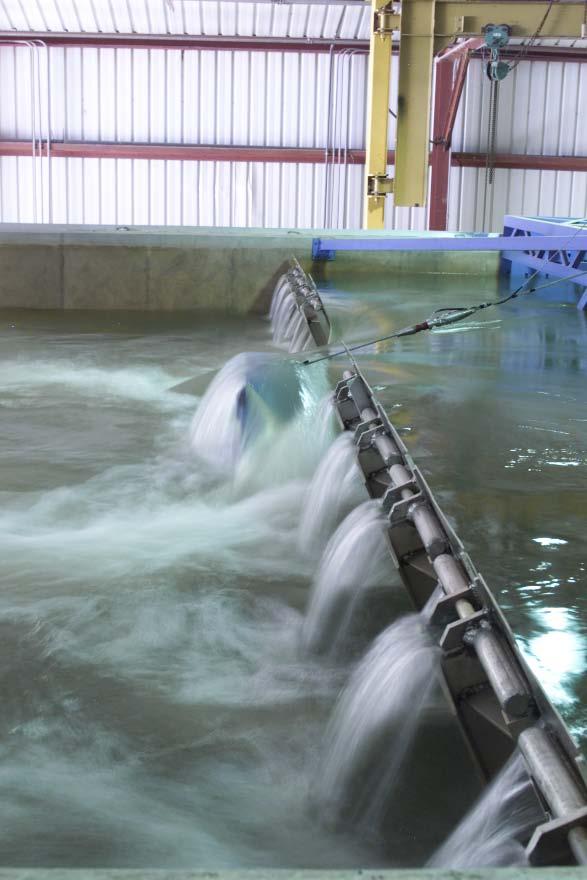
20 Modeling Stilling Basin Formation of hydraulic jump is primary design objective. Other interests concern forces on baffle blocks, pressure fluctuations on the basin floor, walls, and end sill. Scour downstream of basin (rip rap stability). FLOW 20


21 High-Speed Flow, Rough Water Surface, High Condition 4, 190,000 cfs Re, Large V and P Fluctuations Stilling basin performance: Photos of a 1:65-scale model illustrate the variation of the air entrainment and roughness of the air/water interface. Condition 5, 360,000 cfs Condition 6, 460,000 cfs Condition 7, 570,000 cfs Condition 8, 730,000 cfs Condition 9, 860,000 cfs Condition 10, 900,000 cfs 21


22 Scour Downstream of Stilling Basins Consequence of Poor Modeling can be Costly Scour Repair Placing Rip Rap in the Wet Dewatered Stilling Basin for Scour Repair 22
23 Decisions Common to Either Model Method Section Model or General Model? Model Limits you never have too much approach reproduced Boundary Conditions inflow, tailwater, geometry NOTE: Poor Geometry Information is the most common source of errors (numerical and physical models) 23


24 Section Model Decisions Hydraulic: Larger Scale Computational: Finer Mesh Balance scale with flume width and the number of features reproduced Symmetry is important How many gate bays? How many sluices? 24


25 Section Models 1:36-Scale Spillway Section Model 1:25-Scale Penstock Section Model 25


26 FLOW Bluestone Dam 1:25-Scale Penstock Section Model FLOW FLOW 26


27 Olmsted Wicket Gate 1:5-Scale Section Model 27


28 1:5 Model Wicket Gate Raising Forces 28

29 1:5 Model Wicket Gate Raising Forces 29
30 Credentials: Demonstrated Capability USACE must deliver defendable solutions Publish validation study the accuracy of a particular modeling method must be demonstrated, e.g. Observations vs. Calculations (same scale) Same scale avoids differences in viscous forces (same Re in computation and observation system) Peer review publication (available to public) 30
31 References: Model Verification and Validation Roache, P. J., 1998a. Verification and Validation in Computational Science and Engineering, Hermosa Publishers, Albuquerque, August Roache, P. J., Perspective: Validation-what does it mean?, Journal of Fluids Engineering, vol. 131, pp Department of Defense, DoD Modeling and Simulation M&S Verification, Validation, and Accreditation VV&A, DoD Instruction No Department of Defense, 1994, DoD Modeling and Simulation M&S Management, DoD Directive No AIAA, 1998, Guide for the Verification and Validation of Computational Fluid Dynamics Simulations, American Institute of Aeronautics and Astronautics, Reston, VA. ASME Committee PTC-60, 2006, ANSI Standard V&V 10. ASME Guide on Verification and Validation in Computational Solid Mechanics. ASME Committee PTC-61, 2008, ANSI Standard V&V 20. ASME Guide on Verification and Validation in Computational Fluid Dynamics and Heat Transfer. ASCE/EWRI Task Committee, 2009, 3D Free Surface Flow Model Verification/Validation. 31
32 Effective Communication Requires Correct use of Terms Definitions and descriptions for terms related to Verification and Validation of computational hydraulic models Distinction made between Verification vs. Validation Verification is completed by the Code Developer Validation is completed by the Model User Distinctions made between: Numerical Errors vs. Conceptual Modeling Errors Confirmation, Calibration, Tuning, and Certification Verification of Numerical Accuracy of Codes Physical Process Validation vs. Site Validation. 32
33 Distinction between Code Verification and Model Validation Meanings Verification ~ solving the equations right Validation ~ solving the right equations Validations, unlike Verifications, are based on comparisons with experiments (must be at same Reynolds Number). Validation requires error tolerances. There are three distinct sets of uncertainty estimates in a Validation: one associated with the experiments, one with the calculations, and one that defines agreement between the two What levels are acceptable depends on the use intended. Another difference is that Verification is completed whereas Validation is ongoing. 33
34 Say What You Mean and Mean What You Say Validation Considerations: Captures flow features Run computational model at same size as observations (model the model) Re is important and so must be the same in the computational model and observed data We know Darcy s f, so once validated at model scale, we re comfortable with prototype scale solutions Consider not using the term Calibrate since it has connotations of changing coefficient values to match observed data without concern for reasonableness of value Must answer the question How good is good enough? 34
35 1D = One-Dimensional 2D = Two-Dimensional 3D = Three-Dimensional NS = Navier-Stokes Model Methods Notes on Abbreviations SW = Shallow-Water Equations (may be 2D or 3D, but uses hydrostatic assumption) D/S = Downstream 35
36 Hydraulic Evaluation of Current Choice of Model Typical Scale Physical Model Well- Captured Physics Not Well- Captured Physics Typical Eqns Numerical Model Well- Captured Physics Not Well- Captured Physics Lock filling and emptying systems Physical model with 1D model for feasibility 1:25 Hawser forces, culvert pressures Scale effects on filling times and intake vortices, air requirement D/S of culvert valves 1D energy 1D provides systems information but no details Moving components (valves, gates), certain turbulence effects, vortex tendencies, air requirements Navigation conditions at lock approaches Physical model 1:100 Flow, vessel influence, human response There are scale effects that affect flow distributions, human response is from bird seye view, wind effects Not modeled, but would require 2D SW Flow and vessel interaction There are limitations using 2D SW, human response, vessel operation 36
37 Hydraulic Evaluation of Current Choice of Model Typical Scale Physical Model Well-Captured Physics Not Well- Captured Physics Typical Eqns Numerical Model Well- Captured Physics Not Well- Captured Physics Spillways (section model) Physical model 1:25 Discharge capacity, cavitation potential; stilling basin performance; bed protection D/S; loadings on the basin floor, endsill and baffles; deflector performance for fish 3D effects = lateral variations at the dam, air entrainment at water surface and in slot aerators Not modeled but would require mature 3D NS with turb model and free surface capturing Boundary layer, small scale turb. and cavitation potential, air entrainment Pump intakes Physical model Required by ANSI/ Hydraulic Institute Standards 1:10 to 1:15 Vortex formation in vicinity, swirl in the pump column, velocity dist. in intake 37
38 Hydraulic Evaluation of Current Choice of Model Typical Scale Physical Model Well- Captured Physics Not Well- Captured Physics Typical Eqns Numerical Model Well- Captured Physics Not Well- Captured Physics Closed conduit such as outlet works Physical model 1:25 Complex flow and geometry at intake, pressure fluctuations due to turb., potential for slug flow Conduit energy losses due to friction (the conduit is too rough) 1D energy provides system information, 3D NS provides details Friction losses 3D model requires freesurface capabilities to capture slug flow Vessel effects: mooring forces, env. impact Physical and/or 2D SW numerical model 1:25 2D SW Long period wave effects Short period waves Hydraulic component Physical and/or 3D NS numerical model 1:10 to 1:20 Loss coefficients, flow patterns, pressures 38 Not modeled, but requires mature 3D NS with turb.
39 Summary Examples of features that are difficult to compute Rough free surface Non-hydrostatic flow Free shear (jet expansion) Turbulent fluctuations (pressure fluctuations needed for structural design) Fluid/structure interaction with human response Use appropriate terms Modeler and model system must have demonstrated capability 39
40 Additional Information Regarding Near- Field Flow Modeling Can Be Obtained from the Following USACE Engineers Allen Hammack Research Mechanic Engineer Coastal & Hydraulics Laboratory US Army Engineer R&D Center CEERD-HN-NL Dr. Laurie Ebner Regional Technical Expert, Computational Fluid Dynamics Portland District CENWP-EC-HD 40

41 Questions? 41
Three Dimensional Numerical Simulation of Turbulent Flow Over Spillways
 Three Dimensional Numerical Simulation of Turbulent Flow Over Spillways Latif Bouhadji ASL-AQFlow Inc., Sidney, British Columbia, Canada Email: lbouhadji@aslenv.com ABSTRACT Turbulent flows over a spillway
CHAPTER 7 FLOOD HYDRAULICS & HYDROLOGIC VIVEK VERMA
 CHAPTER 7 FLOOD HYDRAULICS & HYDROLOGIC VIVEK VERMA CONTENTS 1. Flow Classification 2. Chezy s and Manning Equation 3. Specific Energy 4. Surface Water Profiles 5. Hydraulic Jump 6. HEC-RAS 7. HEC-HMS
3D numerical modeling of flow along spillways with free surface flow. Complementary spillway of Salamonde.
 3D numerical modeling of flow along spillways with free surface flow. Complementary spillway of Salamonde. Miguel Rocha Silva Instituto Superior Técnico, Civil Engineering Department 1. INTRODUCTION Throughout
Prepared for CIVE 401 Hydraulic Engineering By Kennard Lai, Patrick Ndolo Goy & Dr. Pierre Julien Fall 2015
 Prepared for CIVE 401 Hydraulic Engineering By Kennard Lai, Patrick Ndolo Goy & Dr. Pierre Julien Fall 2015 Contents Introduction General Philosophy Overview of Capabilities Applications Computational
MODELLING THE FLOW AROUND AN ISLAND AND A HEADLAND: APPLICATION OF A TWO MIXING LENGTH MODEL WITH TELEMAC3D. Nicolas Chini 1 and Peter K.
 MODELLING THE FLOW AROUND AN ISLAND AND A HEADLAND: APPLICATION OF A TWO MIXING LENGTH MODEL WITH TELEMAC3D Nicolas Chini 1 and Peter K. Stansby 2 Numerical modelling of the circulation around islands
INTRODUCTION TO HEC-RAS
 INTRODUCTION TO HEC-RAS HEC- RAS stands for Hydrologic Engineering Center s River Analysis System By U.S. Army Corps of Engineers One dimensional analysis of : 1. Steady flow 2. Unsteady flow 3. Sediment
Introducion to Hydrologic Engineering Centers River Analysis System (HEC- RAS) Neena Isaac Scientist D CWPRS, Pune -24
 Neena Isaac Scientist D CWPRS, Pune -24") Introducion to Hydrologic Engineering Centers River Analysis System (HEC- RAS) Neena Isaac Scientist D CWPRS, Pune -24 One dimensional river models (1-D models) Assumptions Flow is one dimensional Streamline
Introducion to Hydrologic Engineering Centers River Analysis System (HEC- RAS) Neena Isaac Scientist D CWPRS, Pune -24 One dimensional river models (1-D models) Assumptions Flow is one dimensional Streamline
COMPARISON OF NUMERICAL HYDRAULIC MODELS APPLIED TO THE REMOVAL OF SAVAGE RAPIDS DAM NEAR GRANTS PASS, OREGON
 COMPARISON OF NUMERICAL HYDRAULIC MODELS APPLIED TO THE REMOVAL OF SAVAGE RAPIDS DAM NEAR GRANTS PASS, OREGON Jennifer Bountry, Hydraulic Engineer, Bureau of Reclamation, Denver, CO, jbountry@do.usbr.gov;
Coastal impact of a tsunami Review of numerical models
 Coastal impact of a tsunami Review of numerical models Richard Marcer 2 Content Physics to simulate Different approaches of modelling 2D depth average Full 3D Navier-Stokes 3D model Key point : free surface
Aalborg Universitet. Numerical 3-D Modelling of Overflows Larsen, Torben; Nielsen, L.; Jensen, B.; Christensen, E. D.
 Aalborg Universitet Numerical 3-D Modelling of Overflows Larsen, Torben; Nielsen, L.; Jensen, B.; Christensen, E. D. Published in: Confernce Proceedings : 11th International Conference on Urban Drainage
QUASI-3D SOLVER OF MEANDERING RIVER FLOWS BY CIP-SOROBAN SCHEME IN CYLINDRICAL COORDINATES WITH SUPPORT OF BOUNDARY FITTED COORDINATE METHOD
 QUASI-3D SOLVER OF MEANDERING RIVER FLOWS BY CIP-SOROBAN SCHEME IN CYLINDRICAL COORDINATES WITH SUPPORT OF BOUNDARY FITTED COORDINATE METHOD Keisuke Yoshida, Tadaharu Ishikawa Dr. Eng., Tokyo Institute
Verification and Validation of HEC-RAS 5.1
 Verification and Validation of HEC-RAS 5.1 Gary Brunner 1, P.E., D. WRE, M.ASCE Dr. Alex Sanchez 1 Dr. Tom Molls 2 Dr. David Parr 3 1. USACE Hydrologic Engineering Center, Davis, CA 2. David Ford Consulting
Paper Comparison of Scale Model Measurements and 3D CFD Simulations of Loss Coefficients and Flow Patterns for Lock Levelling Systems
 Paper 105 - Comparison of Scale Model Measurements and 3D CFD Simulations of Loss Coefficients and Flow Patterns for Lock Levelling Systems VAN DER VEN, P.P.D., VAN VELZEN, G., O MAHONEY, T.S.D., DE LOOR,
Driven Cavity Example
 BMAppendixI.qxd 11/14/12 6:55 PM Page I-1 I CFD Driven Cavity Example I.1 Problem One of the classic benchmarks in CFD is the driven cavity problem. Consider steady, incompressible, viscous flow in a square
Day 1. HEC-RAS 1-D Training. Rob Keller and Mark Forest. Break (9:45 am to 10:00 am) Lunch (12:00 pm to 1:00 pm)
 Lunch (12:00 pm to 1:00 pm)") Day 1 HEC-RAS 1-D Training Rob Keller and Mark Forest Introductions and Course Objectives (8:00 am to 8:15 am) Introductions: Class and Content Module 1 Open Channel Hydraulics (8:15 am to 9:45 am) Lecture
Day 1 HEC-RAS 1-D Training Rob Keller and Mark Forest Introductions and Course Objectives (8:00 am to 8:15 am) Introductions: Class and Content Module 1 Open Channel Hydraulics (8:15 am to 9:45 am) Lecture
Report as of FY2007 for 2006FL146B: "Complex flows through culvert structures by CFD modeling"
 Report as of FY2007 for 2006FL146B: "Complex flows through culvert structures by CFD modeling" Publications Other Publications: Ozdemir, E. C., Hsu, T.-J. (2007). Flow around Culvert Structures, Internal
Complementarities Between Physical Modelling and Computational Fluid Dynamics for an Ecological Continuity Project
 Utah State University DigitalCommons@USU International Symposium on Hydraulic Structures May 17th, 1:30 PM Complementarities Between Physical Modelling and Computational Fluid Dynamics for an Ecological
Numerical calculation of the wind action on buildings using Eurocode 1 atmospheric boundary layer velocity profiles
 Numerical calculation of the wind action on buildings using Eurocode 1 atmospheric boundary layer velocity profiles M. F. P. Lopes IDMEC, Instituto Superior Técnico, Av. Rovisco Pais 149-1, Lisboa, Portugal
Layout of Presentation
 Specialized Training Course On Modelling For River Engineering Applications On : SSIIM Program (25th -29th September, 2011), Egypt By : Dr: Ahmed Musa Siyam Eng: Elnazir Saad Ali Layout of Presentation
CFD Analysis of a Fully Developed Turbulent Flow in a Pipe with a Constriction and an Obstacle
 CFD Analysis of a Fully Developed Turbulent Flow in a Pipe with a Constriction and an Obstacle C, Diyoke Mechanical Engineering Department Enugu State University of Science & Tech. Enugu, Nigeria U, Ngwaka
CFD ANALYSIS OF OGEE SPILLWAY HYDRUALICS
 CFD ANALYSIS OF OGEE SPILLWAY HYDRUALICS Dolon Banerjee 1 and Dr. Bharat Jhamnani 2 1 M.Tech Student, Department of Civil Engineering, Delhi Technological University 2 Professor, Department of Civil Engineering,
COMPUTATIONAL FLUID DYNAMICS ANALYSIS OF ORIFICE PLATE METERING SITUATIONS UNDER ABNORMAL CONFIGURATIONS
 COMPUTATIONAL FLUID DYNAMICS ANALYSIS OF ORIFICE PLATE METERING SITUATIONS UNDER ABNORMAL CONFIGURATIONS Dr W. Malalasekera Version 3.0 August 2013 1 COMPUTATIONAL FLUID DYNAMICS ANALYSIS OF ORIFICE PLATE
Numerical simulation of the flow field in pump intakes by means of Lattice Boltzmann methods
 IOP Conference Series: Materials Science and Engineering OPEN ACCESS Numerical simulation of the flow field in pump intakes by means of Lattice Boltzmann methods To cite this article: A Schneider et al
Computational Fluid Dynamics (CFD) for Built Environment
 for Built Environment") Computational Fluid Dynamics (CFD) for Built Environment Seminar 4 (For ASHRAE Members) Date: Sunday 20th March 2016 Time: 18:30-21:00 Venue: Millennium Hotel Sponsored by: ASHRAE Oryx Chapter Dr. Ahmad
Computational Fluid Dynamics (CFD) for Built Environment Seminar 4 (For ASHRAE Members) Date: Sunday 20th March 2016 Time: 18:30-21:00 Venue: Millennium Hotel Sponsored by: ASHRAE Oryx Chapter Dr. Ahmad
Numerical Modeling Study for Fish Screen at River Intake Channel ; PH (505) ; FAX (505) ;
 ; FAX (505) ;") Numerical Modeling Study for Fish Screen at River Intake Channel Jungseok Ho 1, Leslie Hanna 2, Brent Mefford 3, and Julie Coonrod 4 1 Department of Civil Engineering, University of New Mexico, Albuquerque,
Numerical Modeling Study for Fish Screen at River Intake Channel Jungseok Ho 1, Leslie Hanna 2, Brent Mefford 3, and Julie Coonrod 4 1 Department of Civil Engineering, University of New Mexico, Albuquerque,
FLOW VISUALISATION AROUND A SOLID SPHERE ON A ROUGH BED UNDER REGULAR WAVES
 FLOW VISUALISATION AROUND A SOLID SPHERE ON A ROUGH BED UNDER REGULAR WAVES H.P.V.Vithana 1, Richard Simons 2 and Martin Hyde 3 Flow visualization using Volumetric Three-component Velocimetry (V3V) was
Hydrodynamic modeling of flow around bridge piers
 Hydrodynamic modeling of flow around bridge piers E. D. Farsirotou*, J. V. Soulis^, V. D. Dermissis* *Aristotle University of Thessaloniki, Civil Engineering Department, Division of Hydraulics and Environmental
Gavin Fields Senior Water Resources Engineer XP Solutions
 Hydraulics 101 Gavin Fields Senior Water Resources Engineer XP Solutions Hydraulics 101 Introduction Structures Hydraulic Model Building Q&A XP Solutions Software for modeling wastewater, stormwater, and
Numerical Modeling of Flow Around Groynes with Different Shapes Using TELEMAC-3D Software
 American Journal of Water Science and Engineering 2016; 2(6): 43-52 http://www.sciencepublishinggroup.com/j/ajwse doi: 10.11648/j.ajwse.20160206.11 Numerical Modeling of Flow Around Groynes with Different
NUMERICAL MODELING STUDY FOR FLOW PATTERN CHANGES INDUCED BY SINGLE GROYNE
 NUMERICAL MODELING STUDY FOR FLOW PATTERN CHANGES INDUCED BY SINGLE GROYNE Jungseok Ho 1, Hong Koo Yeo 2, Julie Coonrod 3, and Won-Sik Ahn 4 1 Research Assistant Professor, Dept. of Civil Engineering,
PUBLISHED VERSION. Originally Published at: PERMISSIONS. 23 August 2015
 PUBLISHED VERSION Yinli Liu, Hao Tang, Zhaofeng Tian, Haifei Zheng CFD simulations of turbulent flows in a twin swirl combustor by RANS and hybrid RANS/LES methods Energy Procedia, 2015 / Jiang, X., Joyce,
INTERNATIONAL JOURNAL OF CIVIL AND STRUCTURAL ENGINEERING Volume 2, No 3, 2012
 INTERNATIONAL JOURNAL OF CIVIL AND STRUCTURAL ENGINEERING Volume 2, No 3, 2012 Copyright 2010 All rights reserved Integrated Publishing services Research article ISSN 0976 4399 Efficiency and performances
Turbulence Modeling. Gilles Eggenspieler, Ph.D. Senior Product Manager
 Turbulence Modeling Gilles Eggenspieler, Ph.D. Senior Product Manager 1 Overview The Role of Steady State (RANS) Turbulence Modeling Overview of Reynolds-Averaged Navier Stokes (RANS) Modeling Capabilities
CFD Project Workflow Guide
 CFD Project Workflow Guide Contents Select a problem with known results for proof-of-concept testing... 1 Set up and run a coarse test case... 2 Select and calibrate numerical methods... 3 Minimize & quantify
Numerical Simulation Study on Aerodynamic Characteristics of the High Speed Train under Crosswind
 2017 2nd International Conference on Industrial Aerodynamics (ICIA 2017) ISBN: 978-1-60595-481-3 Numerical Simulation Study on Aerodynamic Characteristics of the High Speed Train under Crosswind Fan Zhao,
Estimating Vertical Drag on Helicopter Fuselage during Hovering
 Estimating Vertical Drag on Helicopter Fuselage during Hovering A. A. Wahab * and M.Hafiz Ismail ** Aeronautical & Automotive Dept., Faculty of Mechanical Engineering, Universiti Teknologi Malaysia, 81310
ANSYS AIM Tutorial Turbulent Flow Over a Backward Facing Step
 ANSYS AIM Tutorial Turbulent Flow Over a Backward Facing Step Author(s): Sebastian Vecchi, ANSYS Created using ANSYS AIM 18.1 Problem Specification Pre-Analysis & Start Up Governing Equation Start-Up Geometry
STUDY OF FLOW PERFORMANCE OF A GLOBE VALVE AND DESIGN OPTIMISATION
 Journal of Engineering Science and Technology Vol. 12, No. 9 (2017) 2403-2409 School of Engineering, Taylor s University STUDY OF FLOW PERFORMANCE OF A GLOBE VALVE AND DESIGN OPTIMISATION SREEKALA S. K.
Uncertainty Analysis: Parameter Estimation. Jackie P. Hallberg Coastal and Hydraulics Laboratory Engineer Research and Development Center
 Uncertainty Analysis: Parameter Estimation Jackie P. Hallberg Coastal and Hydraulics Laboratory Engineer Research and Development Center Outline ADH Optimization Techniques Parameter space Observation
International Journal of Scientific & Engineering Research Volume 9, Issue 4, April ISSN
 International Journal of Scientific & Engineering Research Volume 9, Issue 4, April-2018 57 The energy dissipation of Stepped Spillways experimentally and numerically A. ShawkyAwad a,t. Hemdan Nasr-Allah
Computational Fluid Dynamics Modeling Applications in the Columbia and Willamette Basins
 Computational Fluid Dynamics Modeling Applications in the Columbia and Willamette Basins Liza Roy, P.E. Hydraulic Engineer Portland District February 18, 2010 US Army Corps of Engineers Focused CFD Modeling
HEC-RAS 3.0 January, 2001 Release Notes
 HEC-RAS 3.0 January, 2001 Release Notes A new version of HEC-RAS (3.0) has been released with significant new features over the previous version (2.21). Version 3.0 includes unsteady flow routing capabilities,
NUMERICAL FLOW ANALYSIS FOR SPILLWAYS ABSTRACT
 NUMERICAL FLOW ANALYSIS FOR SPILLWAYS David Ho 1, Karen Boyes 2, Shane Donohoo 3 and Brian Cooper 4 1, 2, 3 Advanced Analysis, Worley Pty Ltd, Sydney, Australia. Email: David.Ho@worley.com.au phone: (02)
Prof. B.S. Thandaveswara. The computation of a flood wave resulting from a dam break basically involves two
 41.4 Routing The computation of a flood wave resulting from a dam break basically involves two problems, which may be considered jointly or seperately: 1. Determination of the outflow hydrograph from the
Physical Modeling and CFD Comparison: Case Study of a Hydro-Combined Power Station in Spillway Mode
 Utah State University DigitalCommons@USU International Junior Researcher and Engineer Workshop on Hydraulic Structures Jun 17th, 12:00 AM - Jun 20th, 12:00 AM Physical Modeling and CFD Comparison: Case
FLOODPLAIN MODELING MANUAL. HEC-RAS Procedures for HEC-2 Modelers
 FLOODPLAIN MODELING MANUAL HEC-RAS Procedures for HEC-2 Modelers Federal Emergency Management Agency Mitigation Directorate 500 C Street, SW Washington, DC 20472 April 2002 Floodplain Modeling Manual HEC-RAS
SIMULATION OF FREE SURFACE FLOW IN A SPILLWAY WITH THE RIGID LID AND VOLUME OF FLUID METHODS AND VALIDATION IN A SCALE MODEL
 V European Conference on Computational Fluid Dynamics ECCOMAS CFD 21 J. C. F. Pereira and A. Sequeira (Eds) Lisbon, Portugal, 14 17 June 21 SIMULATION OF FREE SURFACE FLOW IN A SPILLWAY WITH THE RIGID
Automating Hydraulic Analysis v 1.0.
 2011 Automating Hydraulic Analysis v 1.0. Basic tutorial and introduction Automating Hydraulic Analysis (AHYDRA) is a freeware application that automates some specific features of HEC RAS or other hydraulic
International Engineering Research Journal Numerical Modeling of Flow over Ogee Crested Spillway under Radial Gate
 Numerical Modeling of Flow over Ogee Crested Spillway under Radial Vishal Date 1, Tapobrata Dey 1 and Shashikant Joshi 2 1 Mechanical Engineering Dept., D Y Patil College of Engineering Akurdi, SPPU, Pune,
Extension and Validation of the CFX Cavitation Model for Sheet and Tip Vortex Cavitation on Hydrofoils
 Extension and Validation of the CFX Cavitation Model for Sheet and Tip Vortex Cavitation on Hydrofoils C. Lifante, T. Frank, M. Kuntz ANSYS Germany, 83624 Otterfing Conxita.Lifante@ansys.com 2006 ANSYS,
Computational Fluid Dynamics modeling of a Water Flow Over an Ogee Profile
 FINITE ELEMENT METHOD TECHNICAL REPORT Computational Fluid Dynamics modeling of a Water Flow Over an Ogee Profile ANSYS CFX 12 ENME 547 Dr. Sudak Matias Sessarego Written Report Due Date: Friday December
Stream Function-Vorticity CFD Solver MAE 6263
 Stream Function-Vorticity CFD Solver MAE 66 Charles O Neill April, 00 Abstract A finite difference CFD solver was developed for transient, two-dimensional Cartesian viscous flows. Flow parameters are solved
Axisymmetric Viscous Flow Modeling for Meridional Flow Calculation in Aerodynamic Design of Half-Ducted Blade Rows
 Memoirs of the Faculty of Engineering, Kyushu University, Vol.67, No.4, December 2007 Axisymmetric Viscous Flow Modeling for Meridional Flow alculation in Aerodynamic Design of Half-Ducted Blade Rows by
A Comparative CFD Analysis of a Journal Bearing with a Microgroove on the Shaft & Journal
 Proceedings of International Conference on Innovation & Research in Technology for Sustainable Development (ICIRT 2012), 01-03 November 2012 182 A Comparative CFD Analysis of a Journal Bearing with a Microgroove
Validation of CFD Simulation with Scaled Physical Model of Tailings Dissipation Boxes
 Validation of CFD Simulation with Scaled Physical Model of Tailings Dissipation Boxes José Facusse Ingeniero Mecánico Daniel Manzo Ingeniero Hidráulico PRESENTATION TOPICS Company Overview; Problem Description;
Quantifying the Dynamic Ocean Surface Using Underwater Radiometric Measurement
 DISTRIBUTION STATEMENT A. Approved for public release; distribution is unlimited. Quantifying the Dynamic Ocean Surface Using Underwater Radiometric Measurement Lian Shen Department of Mechanical Engineering
Non-Newtonian Transitional Flow in an Eccentric Annulus
 Tutorial 8. Non-Newtonian Transitional Flow in an Eccentric Annulus Introduction The purpose of this tutorial is to illustrate the setup and solution of a 3D, turbulent flow of a non-newtonian fluid. Turbulent
Comparison of Central and Upwind Flux Averaging in Overlapping Finite Volume Methods for Simulation of Super-Critical Flow with Shock Waves
 Proceedings of the 9th WSEAS International Conference on Applied Mathematics, Istanbul, Turkey, May 7, 6 (pp55665) Comparison of and Flux Averaging in Overlapping Finite Volume Methods for Simulation of
EXPERIMENTAL OBSERVATIONS AND NUMERICAL SIMULATIONS OF A FREE-SURFACE VORTEX IN A TEST VESSEL
 6 th IAHR International Meeting of the Workgroup on Cavitation and Dynamic Problems in Hydraulic Machinery and Systems, September 9-11, 2015, Ljubljana, Slovenia EXPERIMENTAL OBSERVATIONS AND NUMERICAL
Verification and Validation in CFD and Heat Transfer: ANSYS Practice and the New ASME Standard
 Verification and Validation in CFD and Heat Transfer: ANSYS Practice and the New ASME Standard Dimitri P. Tselepidakis & Lewis Collins ASME 2012 Verification and Validation Symposium May 3 rd, 2012 1 Outline
Modeling a Nozzle in a Borehole
 Modeling a Nozzle in a Borehole E. Holzbecher, F. Sun Georg-August Universität Göttingen *Goldschmidtstr. 3, 37077 Göttingen, GERMANY; E-mail: eholzbe@gwdg.de Abstract: A nozzle, installed in an injecting
STAR-CCM+: Wind loading on buildings SPRING 2018
 STAR-CCM+: Wind loading on buildings SPRING 2018 1. Notes on the software 2. Assigned exercise (submission via Blackboard; deadline: Thursday Week 3, 11 pm) 1. NOTES ON THE SOFTWARE STAR-CCM+ generates
Design Optimization of a Subsonic Diffuser. for a Supersonic Aircraft
 Chapter 5 Design Optimization of a Subsonic Diffuser for a Supersonic Aircraft 5. Introduction The subsonic diffuser is part of the engine nacelle leading the subsonic flow from the intake to the turbo-fan
Possibility of Implicit LES for Two-Dimensional Incompressible Lid-Driven Cavity Flow Based on COMSOL Multiphysics
 Possibility of Implicit LES for Two-Dimensional Incompressible Lid-Driven Cavity Flow Based on COMSOL Multiphysics Masanori Hashiguchi 1 1 Keisoku Engineering System Co., Ltd. 1-9-5 Uchikanda, Chiyoda-ku,
Investigation of the critical submergence at pump intakes based on multiphase CFD calculations
 Advances in Fluid Mechanics X 143 Investigation of the critical submergence at pump intakes based on multiphase CFD calculations P. Pandazis & F. Blömeling TÜV NORD SysTec GmbH and Co. KG, Germany Abstract
Numerical Computation of Inception Point Location for Steeply Sloping Stepped Spillways
 9 th International ongress on ivil Engineering, May 8-, 22 Numerical omputation of Inception Point Location for Steeply Sloping Stepped Spillways Mohammad Sarfaraz, Jalal Attari 2 and Michael Pfister 3
Solving non-hydrostatic Navier-Stokes equations with a free surface
 Solving non-hydrostatic Navier-Stokes equations with a free surface J.-M. Hervouet Laboratoire National d'hydraulique et Environnement, Electricite' De France, Research & Development Division, France.
Ultrasonic Flow Measurement for Pipe Installations with Non-Ideal Conditions
 Utah State University DigitalCommons@USU All Graduate Theses and Dissertations Graduate Studies 10-2011 Ultrasonic Flow Measurement for Pipe Installations with Non-Ideal Conditions Devin M. Stoker Utah
HYDRODYNAMIC FORCES ON A SPILLWAY: CAN WE CALCULATE THEM? Abstract. Introduction
 HYDRODYNAMIC FORCES ON A SPILLWAY: CAN WE CALCULATE THEM? Bruce M. Savage, Ph.D., P.E., Dept of Civil Engineering, Idaho State University Michael C. Johnson,Ph.D., P.E., Utah Water Research Laboratory,
Development of Hybrid Fluid Jet / Float Polishing Process
 COMSOL Conference - Tokyo 2013 Development of Hybrid Fluid Jet / Float Polishing Process A. Beaucamp, Y. Namba Dept. of Mechanical Engineering, Chubu University, Japan Zeeko LTD, United Kingdom Research
CHAPTER 3. Elementary Fluid Dynamics
 CHAPTER 3. Elementary Fluid Dynamics - Understanding the physics of fluid in motion - Derivation of the Bernoulli equation from Newton s second law Basic Assumptions of fluid stream, unless a specific
NUMERICAL SIMULATIONS OF FLOW THROUGH AN S-DUCT
 NUMERICAL SIMULATIONS OF FLOW THROUGH AN S-DUCT 1 Pravin Peddiraju, 1 Arthur Papadopoulos, 2 Vangelis Skaperdas, 3 Linda Hedges 1 BETA CAE Systems USA, Inc., USA, 2 BETA CAE Systems SA, Greece, 3 CFD Consultant,
CIBSE Application Manual AM11 Building Performance Modelling Chapter 6: Ventilation Modelling
 Contents Background Ventilation modelling tool categories Simple tools and estimation techniques Analytical methods Zonal network methods Computational Fluid Dynamics (CFD) Semi-external spaces Summary
HECRAS 2D: Are you ready for the revolution in the world of hydraulic modeling?
 HECRAS 2D: Are you ready for the revolution in the world of hydraulic modeling? Rishab Mahajan, Emily Campbell and Matt Bardol March 8, 2017 Outline Reasons for hydraulic modeling 1D Modeling 2D Modeling-
Simulation of Flood Scenarios with Combined 2D/3D Numerical Models
 ICHE 2014, Hamburg - Lehfeldt & Kopmann (eds) - 2014 Bundesanstalt für Wasserbau ISBN 978-3-939230-32-8 Simulation of Flood Scenarios with Combined 2D/3D Numerical Models N. Gerstner, F. Belzner & C. Thorenz
Coastal and Hydraulics Laboratory
 ERDC/CHL TR-0X-X Three Dimensional Shallow Water Adaptive Hydraulics (ADH-SW3): Hydrodynamic Verification and Validation Gaurav Savant, R. Charlie Berger, Tate O. McAlpin and Corey J. Trahan January 2014
Channel Routing & Lakes/Reservoirs in WRF-Hydro
 Channel Routing & Lakes/Reservoirs in WRF-Hydro L. Read, D. Yates National Center for Atmospheric Research Channel Routing Channel Routing Methods Set in hydro.namelist with the channel_option = 1, 2 or
Debojyoti Ghosh. Adviser: Dr. James Baeder Alfred Gessow Rotorcraft Center Department of Aerospace Engineering
 Debojyoti Ghosh Adviser: Dr. James Baeder Alfred Gessow Rotorcraft Center Department of Aerospace Engineering To study the Dynamic Stalling of rotor blade cross-sections Unsteady Aerodynamics: Time varying
Civil Engineering Journal
 Available online at www.civilejournal.org Civil Engineering Journal Vol. 2, No. 1, January, 2016 An Experimental and Numerical Comparison of Flow Hydraulic Parameters in Circular Crested Weir Using Farhad
3D-Numerical Simulation of the Flow in Pool and Weir Fishways Hamid Shamloo*, Shadi Aknooni*
 XIX International Conference on Water Resources CMWR 2012 University of Illinois at Urbana-Champaign June 17-22, 2012 3D-Numerical Simulation of the Flow in Pool and Weir Fishways Hamid Shamloo*, Shadi
Comparing HEC-RAS v5.0 2-D Results with Verification Datasets
 Comparing HEC-RAS v5.0 2-D Results with Verification Datasets Tom Molls 1, Gary Brunner 2, & Alejandro Sanchez 2 1. David Ford Consulting Engineers, Inc., Sacramento, CA 2. USACE Hydrologic Engineering
VALIDATION AND VERIFICATION OF HULL RESISTANCE COMPONENTS USING A COMMERCIAL CFD CODE SUMMARY
 VALIDATION AND VERIFICATION OF HULL RESISTANCE COMPONENTS USING A COMMERCIAL CFD CODE C.A. Perez G, University of Southampton, UK. Universidad Pontificia Bolivariana, Colombia, M. Tan and P.A. Wilson University
SPC 307 Aerodynamics. Lecture 1. February 10, 2018
 SPC 307 Aerodynamics Lecture 1 February 10, 2018 Sep. 18, 2016 1 Course Materials drahmednagib.com 2 COURSE OUTLINE Introduction to Aerodynamics Review on the Fundamentals of Fluid Mechanics Euler and
Analysis of Flow through a Drip Irrigation Emitter
 International OPEN ACCESS Journal Of Modern Engineering Research (IJMER) Analysis of Flow through a Drip Irrigation Emitter Reethi K 1, Mallikarjuna 2, Vijaya Raghu B 3 1 (B.E Scholar, Mechanical Engineering,
3D Investigation of Seabed Stress Around Subsea Pipelines
 3D Investigation of Seabed Stress Around Subsea Pipelines Wenwen Shen Dr Jeremy Leggoe School of Mechanical and Chemical Engineering Terry Griffiths CEED Client: J P Kenny Abstract Field observations on
Simulation of Flow Development in a Pipe
 Tutorial 4. Simulation of Flow Development in a Pipe Introduction The purpose of this tutorial is to illustrate the setup and solution of a 3D turbulent fluid flow in a pipe. The pipe networks are common
MOMENTUM AND HEAT TRANSPORT INSIDE AND AROUND
 MOMENTUM AND HEAT TRANSPORT INSIDE AND AROUND A CYLINDRICAL CAVITY IN CROSS FLOW G. LYDON 1 & H. STAPOUNTZIS 2 1 Informatics Research Unit for Sustainable Engrg., Dept. of Civil Engrg., Univ. College Cork,
Simulation of Turbulent Axisymmetric Waterjet Using Computational Fluid Dynamics (CFD)
") Simulation of Turbulent Axisymmetric Waterjet Using Computational Fluid Dynamics (CFD) PhD. Eng. Nicolae MEDAN 1 1 Technical University Cluj-Napoca, North University Center Baia Mare, Nicolae.Medan@cunbm.utcluj.ro
Simulation of Turbulent Axisymmetric Waterjet Using Computational Fluid Dynamics (CFD) PhD. Eng. Nicolae MEDAN 1 1 Technical University Cluj-Napoca, North University Center Baia Mare, Nicolae.Medan@cunbm.utcluj.ro
INVESTIGATION OF HYDRAULIC PERFORMANCE OF A FLAP TYPE CHECK VALVE USING CFD AND EXPERIMENTAL TECHNIQUE
 International Journal of Mechanical Engineering and Technology (IJMET) Volume 10, Issue 1, January 2019, pp. 409 413, Article ID: IJMET_10_01_042 Available online at http://www.ia aeme.com/ijmet/issues.asp?jtype=ijmet&vtype=
SCOUR DOWNSTREAM OBLIQUE V-NOTCH WEIR
 Thirteenth International Water Technology Conference, IWTC 3 9, Hurghada, Egypt SCOUR DOWNSTREAM OBLIQUE V-NOTCH WEIR Y. A. Hamed, M. H. El-Kiki and A. M. Mirdan Civil Engineering Department, Faculty of
Modeling Khowr-e Musa Multi-Branch Estuary Currents due to the Persian Gulf Tides Using NASIR Depth Average Flow Solver
 Journal of the Persian Gulf (Marine Science)/Vol.1/No.1/September 2010/6/45-50 Modeling Khowr-e Musa Multi-Branch Estuary Currents due to the Persian Gulf Tides Using NASIR Depth Average Flow Solver Sabbagh-Yazdi,
CFD Best Practice Guidelines: A process to understand CFD results and establish Simulation versus Reality
 CFD Best Practice Guidelines: A process to understand CFD results and establish Simulation versus Reality Judd Kaiser ANSYS Inc. judd.kaiser@ansys.com 2005 ANSYS, Inc. 1 ANSYS, Inc. Proprietary Overview
Background to Rock Roughness Equation
 Background to Rock Roughness Equation WATERWAY MANAGEMENT PRACTICES Photo 1 Rock-lined fish ramp Photo 2 Added culvert bed roughness Introduction Formulas such as the Strickler Equation have been commonly
Using 2D Schemes to Model Energy Losses at Structures and Bends Beware of Pretty Images!
 Using 2D Schemes to Model Energy Losses at Structures and Bends Beware of Pretty Images! Bill Syme BMT WBM Software Business Manager 2D: Looks impressive, but is it accurate? 2 Form Losses Energy dissipated
FLOODPLAIN MODELING USING HEC-RAS
 H A E S T A D M E T H O D S FLOODPLAIN MODELING USING HEC-RAS F i r s t E d i t i o n Authors Haestad Methods Gary Dyhouse Jennifer Hatchett Jeremy Benn Managing Editor Colleen Totz Editors David Klotz,
INVESTIGATION OF DIFFERENT METHODS FOR MODELLING INTERACTION BETWEEN HYDROKINETIC RIVER TURBINES AND WATER SURFACE
 6 th IAHR International Meeting of the Workgroup on Cavitation and Dynamic Problems in Hydraulic Machinery and Systems, September 9-11, 2015, Ljubljana, Slovenia INVESTIGATION OF DIFFERENT METHODS FOR
CDA Workshop Physical & Numerical Hydraulic Modelling. STAR-CCM+ Presentation
 CDA Workshop Physical & Numerical Hydraulic Modelling STAR-CCM+ Presentation ENGINEERING SIMULATION CFD FEA Mission Increase the competitiveness of companies through optimization of their product development
Dimensioning and Airflow Simulation of the Wing of an Ultralight Aircraft
 Dimensioning and Airflow Simulation of the Wing of an Ultralight Aircraft Richárd Molnár 1 Gergely Dezső 2* Abstract: Increasing interest to ultralight aircrafts usually made of composite materials leads
Numerical Simulation of Flow around a Spur Dike with Free Surface Flow in Fixed Flat Bed. Mukesh Raj Kafle
 TUTA/IOE/PCU Journal of the Institute of Engineering, Vol. 9, No. 1, pp. 107 114 TUTA/IOE/PCU All rights reserved. Printed in Nepal Fax: 977-1-5525830 Numerical Simulation of Flow around a Spur Dike with
Numerical Wave Tank Modeling of Hydrodynamics of Permeable Barriers
 ICHE 2014, Hamburg - Lehfeldt & Kopmann (eds) - 2014 Bundesanstalt für Wasserbau ISBN 978-3-939230-32-8 Numerical Wave Tank Modeling of Hydrodynamics of Permeable Barriers K. Rajendra & R. Balaji Indian