Week 12 - Lecture Mechanical Event Simulation. ME Introduction to CAD/CAE Tools
|
|
|
- Leslie King
- 6 years ago
- Views:
Transcription
1 Week 12 - Lecture Mechanical Event Simulation
2 Lecture Topics Mechanical Event Simulation Overview Additional Element Types Joint Component Description General Constraint Refresh Mesh Control

3 Force Estimation Methods Experience Engineers reply on past experience from similar projects to estimate forces. Often results in an over designed product. Rigid-Body Dynamics Leverage the 3D design data to perform a motion simulation using rigid bodies to gain insights into force values. Physical Experimentation Experiment with prototypes or past products to obtain accurate force values.

4 Let s Keep Exploring Simulation

5 Mechanical Event Simulation (MES) Mechanical Event Simulation (MES) combines kinematic, rigid, and flexible-body dynamics, and nonlinear stress analysis. Events with Large Deformations Nonlinear Material Properties Kinematic Motion Forces Caused by Motion Stress Results / Motion Forces


6 MES Use Cases Complete FEA on part throughout complete loading cycle. Conduct a impact test on a product. Validate the motion of flexible body components.

7 Autodesk Simulation Autodesk Simulation helps designers and engineers make decisions earlier and predict product performance. Linear and Nonlinear Static Stress Fatigue Analysis Linear Dynamic Mechanical Event Heat Transfer CFD Multiphysics

8 MES High Level Process Setting up the Model Setup the complete physical event within the model using loads, boundary conditions, contact, and etc. Analyzing the Model Solve the simulation frame by frame for the duration of the event. (Note: Computer Resources Required) Results Evaluation Examine the results of the analysis throughout the timeline of the study.


9 What is Being Introduced in MES Additional Element Types Joint Components Load Curves Gravity

10 Additional Element Types The following additional element types apply to the MES environment. Beam / Truss Spring Actuator Pulley Slider 3-D Kinematic

11 3D Kinematic Element 3D Kinematic elements do not experience strains and as a result do not report or calculate stresses. Elements Have Mass Apply Loads Experience Motion Acts like a Rigid Body

12 Spring Element A spring element can connect two nodes on parts with a defined stiffness value. Axial or Rotational Displays as a Line or 3D Object
13 Slider Element The slider element is used to translation a single node along a defined axis. Requires 3 Connection Nodes Node 3 Slides between Node 1 and 2 Two Lines must be Connect and Parallel Slider Elements can Attach to Beam, Truss, 2D, Brick


14 Actuator Element An actuator element is a two-node element that can either change length or rotate during an analysis. Uses a load curve to control the action.

15 Pulley Element The pulley element is used to represent simple pulleys to rotate objects in most cases. Consists of Three Nodes (Driver, Pivot, and Slack) Can Stay Stationary Can Move with Other Parts
16 Joint Component Joint components are used to simulate joints and pinned connections for rotational purposes. Pin Joint Lines to Axis Endpoints Universal Joint Lines to Axis Midpoint

17 Pin Joints Used instead of modeling a true 3D pin part to allow rotation about the defined axis. Creates truss elements that use pinned connections to allow the bodies to rotate.

18 Universal Joint Creates a part that allows the model to rotate about the axis and swivel about the center point of the axis. All of the space truss elements connect to the center.

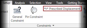
19 General Constraint Boundary Condition The General Constraint establishes boundary conditions to constrain DOF s. Note: Similar to the Autodesk Inventor Professional standard joint features in Dynamic Simulation.

20 Model Mesh Control CAD model mesh options can be controlled at a part level override. This provides the ability to streamline the mesh for the most optimal results for larger assembly based models.
21 Computer-Cluster Projects (CP12)

22 Guided Lab Project 1 Guides instructions for transferring loads from a Dynamic Simulation to a linear FEA.
 with nonlinear")
23 Guided Lab Project 2 Guided instructions for simulating a piston and crank using Mechanical Event Simulation (MES) with nonlinear materials.

24 Guided Lab Project 3 Guided instructions for completing a MES analysis with additional element types and joints.
25 Problem Set Assignment Conceptual Design Validation of Crank Slider Mechanism
26 Demo Topics

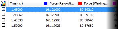

27 Exporting Dynamic Simulation Results

28 Create Simulation with Motion Loads

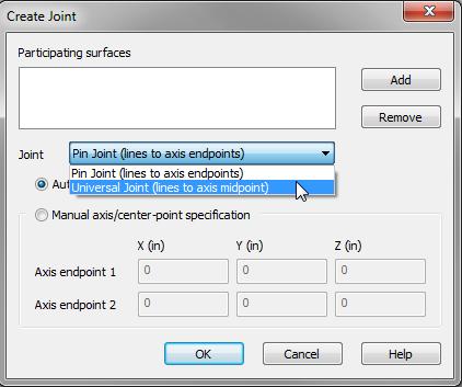
29 Pin and Universal Joints

30 Truss Elements

31 Beam Elements
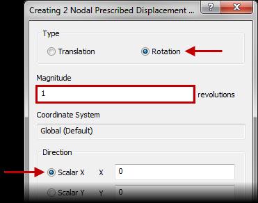
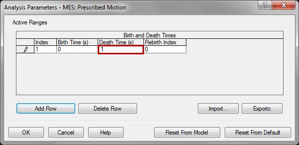
32 Rotational Prescribed Displacement

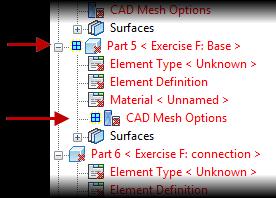

33 Part Mesh Settings
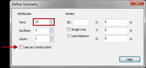
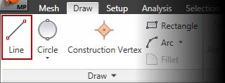

34 Draw Line

35 Actuator Elements
ME Week 12 Piston Mechanical Event Simulation
 Introduction to Mechanical Event Simulation The purpose of this introduction to Mechanical Event Simulation (MES) project is to explorer the dynamic simulation environment of Autodesk Simulation. This
Lesson 6: Assembly Structural Analysis
 Lesson 6: Assembly Structural Analysis In this lesson you will learn different approaches to analyze the assembly using assembly analysis connection properties between assembly components. In addition
Rigid Dynamic Analysis in Workbench
 Rigid Dynamic Analysis in Workbench 1-1 Introduction Rigid Dynamic Analysis: Calculates dynamic response of an assembly of rigid bodies. Can be used to study the kinematics of an assembly. Bodies are linked
Chapter 4. Mechanism Design and Analysis
 Chapter 4. Mechanism Design and Analysis All mechanical devices containing moving parts are composed of some type of mechanism. A mechanism is a group of links interacting with each other through joints
ME Optimization of a Frame
 ME 475 - Optimization of a Frame Analysis Problem Statement: The following problem will be analyzed using Abaqus. 4 7 7 5,000 N 5,000 N 0,000 N 6 6 4 3 5 5 4 4 3 3 Figure. Full frame geometry and loading
Chapter 1 Introduction
 Chapter 1 Introduction Generally all considerations in the force analysis of mechanisms, whether static or dynamic, the links are assumed to be rigid. The complexity of the mathematical analysis of mechanisms
midas NFX An insight into midas NFX
 midas NFX An insight into midas NFX Total Analysis Solutions for Multi-disciplinary Optimum Design Part 1. Work environment Multi-disciplinary CAE solutions in one unique work environment 1 Part 1. Work
SIMULATION CAPABILITIES IN CREO
 SIMULATION CAPABILITIES IN CREO Enhance Your Product Design with Simulation & Using digital prototypes to understand how your designs perform in real-world conditions is vital to your product development
SIMULATION CAPABILITIES IN CREO. Enhance Your Product Design with Simulation & Analysis
 SIMULATION CAPABILITIES IN CREO Enhance Your Product Design with Simulation & Using digital prototypes to understand how your designs perform in real-world conditions is vital to your product development
Spur Gears Static Stress Analysis with Linear Material Models
 Exercise A Spur Gears Static Stress Analysis with Linear Material Models Beam and Brick Elements Objective: Geometry: Determine the stress distribution in the spur gears when a moment of 93.75 in-lb is
Modelling of mechanical system CREATING OF KINEMATIC CHAINS
 Modelling of mechanical system CREATING OF KINEMATIC CHAINS Mechanism Definitions 1. a system or structure of moving parts that performs some function 2. is each system reciprocally joined moveable bodies
Using RecurDyn. Contents
 Using RecurDyn Contents 1.0 Multibody Dynamics Overview... 2 2.0 Multibody Dynamics Applications... 3 3.0 What is RecurDyn and how is it different?... 4 4.0 Types of RecurDyn Analysis... 5 5.0 MBD Simulation
SOLIDWORKS SIMULATION
 SOLIDWORKS SIMULATION Innovation is about taking chances, not taking risks Scootchi by Curventa Designworks LTD What if? is the question that fuels innovation. SolidWorks Simulation software takes the
ME Optimization of a Truss
 ME 475 - Optimization of a Truss Analysis Problem Statement: The following problem will be analyzed using Abaqus and optimized using HEEDS. 4 5 8 2 11 3 10 6 9 1 7 12 6 m 300 kn 300 kn 22 m 35 m Figure
SimWise 4D. Integrated Motion and Stress Analysis
 SimWise 4D Integrated Motion and Stress Analysis SimWise 4D Integrated Motion Simulation and Stress Analysis SimWise 4D is a software tool that allows the functional performance of mechanical parts and
SimWise. 3D Dynamic Motion, and Stress Analysis. integrated with Alibre Design
 SimWise 3D Dynamic Motion, and Stress Analysis integrated with Alibre Design SimWise 4D for Alibre Integrated Motion Simulation and Stress Analysis SimWise 4D is a software tool that allows the functional
Chapter 5 Modeling and Simulation of Mechanism
 Chapter 5 Modeling and Simulation of Mechanism In the present study, KED analysis of four bar planar mechanism using MATLAB program and ANSYS software has been carried out. The analysis has also been carried
New Capabilities in Project Hydra for Autodesk Simulation Mechanical
 New Capabilities in Project Hydra for Autodesk Simulation Mechanical Sualp Ozel, PE. Autodesk SM2447-L In this hands-on lab, we will go through several exercises and cover several new capabilities included
Lesson 1: Introduction to Pro/MECHANICA Motion
 Lesson 1: Introduction to Pro/MECHANICA Motion 1.1 Overview of the Lesson The purpose of this lesson is to provide you with a brief overview of Pro/MECHANICA Motion, also called Motion in this book. Motion
imaginit.com/simulation Complete and robust mechanical simulation solution
 imaginit.com/simulation Complete and robust mechanical simulation solution A mechanical simulation solution for finite imaginit.com/simulation element analysis powered by the Autodesk Nastran solver Accurately
Introduction to Engineering Analysis
 Chapter 1 Introduction to Engineering Analysis This chapter introduces you to the Stress Analysis and Dynamic Simulation environments. You learn how digital prototyping can be used to simulate your designs
Quick Start Guide to midas NFX
 Quick Start Guide to midas NFX This guide is made for non-experienced FEA users. It provides basic knowledge needed to run midas NFX successfully and begin your analysis. Experienced FEA analysts can also
2: Static analysis of a plate
 2: Static analysis of a plate Topics covered Project description Using SolidWorks Simulation interface Linear static analysis with solid elements Finding reaction forces Controlling discretization errors
VD - Design Validation
 Coordinating unit: Teaching unit: Academic year: Degree: ECTS credits: 2017 295 - EEBE - Barcelona East School of Engineering 717 - EGE - Department of Engineering Presentation BACHELOR'S DEGREE IN ELECTRICAL
SolidWorks. An Overview of SolidWorks and Its Associated Analysis Programs
 An Overview of SolidWorks and Its Associated Analysis Programs prepared by Prof. D. Xue University of Calgary SolidWorks - a solid modeling CAD tool. COSMOSWorks - a design analysis system fully integrated
Module 1: Introduction to Finite Element Analysis. Lecture 4: Steps in Finite Element Analysis
 25 Module 1: Introduction to Finite Element Analysis Lecture 4: Steps in Finite Element Analysis 1.4.1 Loading Conditions There are multiple loading conditions which may be applied to a system. The load
ANSYS Element. elearning. Peter Barrett October CAE Associates Inc. and ANSYS Inc. All rights reserved.
 ANSYS Element Selection elearning Peter Barrett October 2012 2012 CAE Associates Inc. and ANSYS Inc. All rights reserved. ANSYS Element Selection What is the best element type(s) for my analysis? Best
Engineering Analysis
 Engineering Analysis with SOLIDWORKS Simulation 2018 Paul M. Kurowski SDC PUBLICATIONS Better Textbooks. Lower Prices. www.sdcpublications.com Powered by TCPDF (www.tcpdf.org) Visit the following websites
ixcube 4-10 Brief introduction for membrane and cable systems.
 ixcube 4-10 Brief introduction for membrane and cable systems. ixcube is the evolution of 20 years of R&D in the field of membrane structures so it takes a while to understand the basic features. You must
Complete and robust mechanical simulation solution. imaginit.com/simulation-mechanical
 Complete and robust mechanical simulation solution A mechanical simulation solution for finite element analysis powered by the Autodesk Nastran solver Accurately predict product behavior, optimize and
Connection Elements and Connection Library
 Connection Elements and Connection Library Lecture 2 L2.2 Overview Introduction Defining Connector Elements Understanding Connector Sections Understanding Connection Types Understanding Connector Local
Kinematics Fundamentals CREATING OF KINEMATIC CHAINS
 Kinematics Fundamentals CREATING OF KINEMATIC CHAINS Mechanism Definitions 1. a system or structure of moving parts that performs some function 2. is each system reciprocally joined moveable bodies the
Creo Simulate 3.0 Tutorial
 Creo Simulate 3.0 Tutorial Structure and Thermal Roger Toogood, Ph.D., P. Eng. SDC PUBLICATIONS Better Textbooks. Lower Prices. www.sdcpublications.com Powered by TCPDF (www.tcpdf.org) Visit the following
SOLIDWORKS Simulation
 SOLIDWORKS Simulation Length: 3 days Prerequisite: SOLIDWORKS Essentials Description: SOLIDWORKS Simulation is designed to make SOLIDWORKS users more productive with the SOLIDWORKS Simulation Bundle. This
Theory of Machines Course # 1
 Theory of Machines Course # 1 Ayman Nada Assistant Professor Jazan University, KSA. arobust@tedata.net.eg March 29, 2010 ii Sucess is not coming in a day 1 2 Chapter 1 INTRODUCTION 1.1 Introduction Mechanisms
PTC Creo Simulate. Features and Specifications. Data Sheet
 PTC Creo Simulate PTC Creo Simulate gives designers and engineers the power to evaluate structural and thermal product performance on your digital model before resorting to costly, time-consuming physical
Reduction of Finite Element Models for Explicit Car Crash Simulations
 Reduction of Finite Element Models for Explicit Car Crash Simulations K. Flídrová a,b), D. Lenoir a), N. Vasseur b), L. Jézéquel a) a) Laboratory of Tribology and System Dynamics UMR-CNRS 5513, Centrale
 Set No. 1 IV B.Tech. I Semester Regular Examinations, November 2010 FINITE ELEMENT METHODS (Mechanical Engineering) Time: 3 Hours Max Marks: 80 Answer any FIVE Questions All Questions carry equal marks
FEA Applications I MET 415 Review Course Structure: 15 week course Weekly Schedule 50 minute lecture 2.5 hour laboratory 50 minute lecture
 FEA Applications I MET 415 Review Course Structure: 15 week course Weekly Schedule 50 minute lecture 2.5 hour laboratory 50 minute lecture Goal: Obtain feedback from Industry Users on course presentation
Overview. What is mechanism? What will I learn today? ME 311: Dynamics of Machines and Mechanisms Lecture 2: Synthesis
 Overview ME 311: Dynamics of Machines and Mechanisms Lecture 2: Synthesis By Suril Shah Some fundamentals Synthesis Function, path and motion generation Limiting condition Dimensional synthesis 1 2 What
midas NFX 2017R1 Release Note
 Total Solution for True Analysis-driven Design midas NFX 2017R1 Release Note 1 midas NFX R E L E A S E N O T E 2 0 1 7 R 1 Major Improvements Midas NFX is an integrated finite element analysis program
WEEKS 1-2 MECHANISMS
 References WEEKS 1-2 MECHANISMS (METU, Department of Mechanical Engineering) Text Book: Mechanisms Web Page: http://www.me.metu.edu.tr/people/eres/me301/in dex.ht Analitik Çözümlü Örneklerle Mekanizma
Modeling Bolted Connections. Marilyn Tomlin CAE COE / Siemens Corporation
 Modeling Bolted Connections Marilyn Tomlin CAE COE / Siemens Corporation Overview Bolted Connection Engineering Judgment Modeling Options Summary Typical Bolted Connection Gasket Bolt Nut Washer Technology
September 20, Chapter 5. Simple Mechanisms. Mohammad Suliman Abuhaiba, Ph.D., PE
 Chapter 5 Simple Mechanisms 1 Mohammad Suliman Abuhaiba, Ph.D., PE 2 Assignment #1 All questions at the end of chapter 1 st Exam: Saturday 29/9/2018 3 Kinematic Link or Element kinematic link (link) or
E and. L q. AE q L AE L. q L
 STRUTURL NLYSIS [SK 43] EXERISES Q. (a) Using basic concepts, members towrds local axes is, E and q L, prove that the equilibrium equation for truss f f E L E L E L q E q L With f and q are both force
Lecture 5 Modeling Connections
 Lecture 5 Modeling Connections 16.0 Release Introduction to ANSYS Mechanical 1 2015 ANSYS, Inc. February 27, 2015 Chapter Overview In this chapter, we will extend the discussion of contact control begun
An Overview of Computer Aided Design and Finite Element Analysis
 An Overview of Computer Aided Design and Finite Element Analysis by James Doane, PhD, PE Contents 1.0 Course Overview... 4 2.0 General Concepts... 4 2.1 What is Computer Aided Design... 4 2.1.1 2D verses
About the Author. Acknowledgements
 About the Author Dr. Paul Kurowski obtained his M.Sc. and Ph.D. in Applied Mechanics from Warsaw Technical University. He completed postdoctoral work at Kyoto University. Dr. Kurowski is an Assistant Professor
MSC.visualNastran Desktop FEA Exercise Workbook. Pin and Bracket Assembly: Vibration Simulation in 4D
 MSC.visualNastran Desktop FEA Exercise Workbook Pin and Bracket Assembly: Vibration Simulation in 4D WS24-2 Objectives This exercise is design to introduce vibration analysis in visualnastran Desktop.
SOLIDWORKS SIMULATION
 SUPPORTING EXCELLENCE GET ENGINEERING INSIGHTS WITH VIRTUAL SOPHISTICATED IS NO LONGER JUST FOR SPECIALISTS Concurrent Engineering for more informed design Simulation gives product engineers access to
2.007 Design and Manufacturing I Spring 2009
 MIT OpenCourseWare http://ocw.mit.edu 2.007 Design and Manufacturing I Spring 2009 For information about citing these materials or our Terms of Use, visit: http://ocw.mit.edu/terms. 2.007 Design and Manufacturing
ME 345: Modeling & Simulation. Introduction to Finite Element Method
 ME 345: Modeling & Simulation Introduction to Finite Element Method Examples Aircraft 2D plate Crashworthiness 2 Human Heart Gears Structure Human Spine 3 F.T. Fisher, PhD Dissertation, 2002 Fluid Flow
Kinematics: Intro. Kinematics is study of motion
 Kinematics is study of motion Kinematics: Intro Concerned with mechanisms and how they transfer and transform motion Mechanisms can be machines, skeletons, etc. Important for CG since need to animate complex
Introduction to FEM Modeling
 Total Analysis Solution for Multi-disciplinary Optimum Design Apoorv Sharma midas NFX CAE Consultant 1 1. Introduction 2. Element Types 3. Sample Exercise: 1D Modeling 4. Meshing Tools 5. Loads and Boundary
Modeling and Simulation for Aircraft Structural Repair Using Modern FEA Tools
 Modeling and Simulation for Aircraft Structural Repair Using Modern FEA Tools December 19-22, 2011 and January 9-12, 2012 Kuang-Hua Chang, Ph.D. Williams Presidential Professor School of Aerospace and
SolidWorks Assembly Files. Assemblies Mobility. The Mating Game Mating features. Mechanical Mates Relative rotation about axes
 Assemblies Mobility SolidWorks Assembly Files An assembly file is a collection of parts The first part brought into an assembly file is fixed Other parts are constrained relative to that part (or other
ME Week 11 Create Joints Project
 One of the most important elements of dynamic simulation is setting up and verifying that proper joints are created. Joints are links between two rigid components that applies force from the first component
Advanced Techniques for Nonlinear Contact and Drop Shock Analysis Shoubing Zhuang Autodesk Inc. Michael Smell Autodesk Inc.
 Advanced Techniques for Nonlinear Contact and Drop Shock Analysis Shoubing Zhuang Autodesk Inc. Michael Smell Autodesk Inc. MA7405-P Are you interested in learning how to use nonlinear contact to simulate
Welcome to MSC.visualNastran 4D. 1.0 Installing MSC.visualNastran 4D
 Welcome to MSC.visualNastran 4D MSC.visualNastran 4D is the result of a twelve-year collaborative effort between professional engineers and software specialists. We are committed to providing you easy-to-use,
About the Author. Acknowledgements
 About the Author Dr. Paul Kurowski obtained his MSc and PhD in Applied Mechanics from Warsaw Technical University. He completed postdoctoral work at Kyoto University. Dr. Kurowski is an Assistant Professor
Introduction to ANSYS Mechanical
 Lecture 6 Modeling Connections 15.0 Release Introduction to ANSYS Mechanical 1 2012 ANSYS, Inc. February 12, 2014 Chapter Overview In this chapter, we will extend the discussion of contact control begun
Connecting through the Cloud
 Interdisciplinary Engineering Design Education Conference 2013 Connecting through the Cloud Thom Tremblay Global Design, Lifecycle, and Simulation Industry Manager 2013 Autodesk A World Leader in 2D and
Spatial R-C-C-R Mechanism for a Single DOF Gripper
 NaCoMM-2009-ASMRL28 Spatial R-C-C-R Mechanism for a Single DOF Gripper Rajeev Lochana C.G * Mechanical Engineering Department Indian Institute of Technology Delhi, New Delhi, India * Email: rajeev@ar-cad.com
Global to Local Model Interface for Deepwater Top Tension Risers
 Global to Local Model Interface for Deepwater Top Tension Risers Mateusz Podskarbi Karan Kakar 2H Offshore Inc, Houston, TX Abstract The water depths from which oil and gas are being produced are reaching
Efficient Shape Optimisation of an Aircraft Landing Gear Door Locking Mechanism by Coupling Abaqus to GENESIS
 Efficient Shape Optimisation of an Aircraft Landing Gear Door Locking Mechanism by Coupling Abaqus to GENESIS Mark Arnold and Martin Gambling Penso Consulting Ltd GRM Consulting Ltd Abstract: The objective
ME 321 Kinematics and Dynamics of Machines
 .0 INTRODUCTION ME Kinematics and Dynamics of Machines All Text References in these notes are for: Mechanism Design: Analysis and Synthesis, Volume, Fourth Edition, Erdman, Sandor and Kota, Prentice-Hall,
Model Library Mechanics
 Model Library Mechanics Using the libraries Mechanics 1D (Linear), Mechanics 1D (Rotary), Modal System incl. ANSYS interface, and MBS Mechanics (3D) incl. CAD import via STL and the additional options
Simulation of Overhead Crane Wire Ropes Utilizing LS-DYNA
 Simulation of Overhead Crane Wire Ropes Utilizing LS-DYNA Andrew Smyth, P.E. LPI, Inc., New York, NY, USA Abstract Overhead crane wire ropes utilized within manufacturing plants are subject to extensive
SOEM 024: Computer Aided Design. E. Rozos
 SOEM 024: Computer Aided Design E. Rozos Lesson structure Construct 3D objects with revolving WCS UCS Master plotting Realism Geometrical analysis Stress analysis Kinematics dynamic simulation Revolve,
ME scope Application Note 04 Using SDM for Sub-Structuring
 App Note 04 www.vibetech.com 2-Aug-18 ME scope Application Note 04 Using SDM for Sub-Structuring NOTE: The steps in this Application Note can be duplicated using any Package that includes the VES-5000
course outline basic principles of numerical analysis, intro FEM
 idealization, equilibrium, solutions, interpretation of results types of numerical engineering problems continuous vs discrete systems direct stiffness approach differential & variational formulation introduction
Chapter 1 Introduction
 Chapter 1 Introduction GTU Paper Analysis (New Syllabus) Sr. No. Questions 26/10/16 11/05/16 09/05/16 08/12/15 Theory 1. What is graphic standard? Explain different CAD standards. 2. Write Bresenham s
ROSE-HULMAN INSTITUTE OF TECHNOLOGY
 Introduction to Working Model Welcome to Working Model! What is Working Model? It's an advanced 2-dimensional motion simulation package with sophisticated editing capabilities. It allows you to build and
Introduction to Finite Element Analysis using ANSYS
 Introduction to Finite Element Analysis using ANSYS Sasi Kumar Tippabhotla PhD Candidate Xtreme Photovoltaics (XPV) Lab EPD, SUTD Disclaimer: The material and simulations (using Ansys student version)
LIGO Scissors Table Static Test and Analysis Results
 LIGO-T980125-00-D HYTEC-TN-LIGO-31 LIGO Scissors Table Static Test and Analysis Results Eric Swensen and Franz Biehl August 30, 1998 Abstract Static structural tests were conducted on the LIGO scissors
DYNAMIC MODELING OF WORKING SECTIONS OF GRASSLAND OVERSOWING MACHINE MSPD-2.5
 DYNAMIC MODELING OF WORKING SECTIONS OF GRASSLAND OVERSOWING MACHINE MSPD-2.5 Florin Loghin, Simion Popescu, Florean Rus Transilvania University of Brasov, Romania loghinflorin@unitbv.ro, simipop@unitbv.ro,
Background CE 342. Why RISA-2D? Availability
 Background CE 342 RISA-2D RISA-2D is a structural analysis program, which can model: Beams, frames, trusses and plates. Any linear elastic structural material. Typical supports, such as pins, rollers and
Principles of Kinematic Constraint
 Principles of Kinematic Constraint For holding a body (rigid thing) with the highest precision, we require: Full 6 DoF constraint If 6 DoFs not fully constrained, then one is loose. No overconstraint Any
UNDERSTANDING MOTION SIMULATION
 W H I T E P A P E R UNDERSTANDING MOTION SIMULATION Overview What is motion simulation? What problems can it solve? How can it benefit the product design process? This paper addresses some of these issues
PTC Newsletter January 14th, 2002
 PTC Email Newsletter January 14th, 2002 PTC Product Focus: Pro/MECHANICA (Structure) Tip of the Week: Creating and using Rigid Connections Upcoming Events and Training Class Schedules PTC Product Focus:
Session #5 2D Mechanisms: Mobility, Kinematic Analysis & Synthesis
 Session #5 2D Mechanisms: Mobility, Kinematic Analysis & Synthesis Courtesy of Design Simulation Technologies, Inc. Used with permission. Dan Frey Today s Agenda Collect assignment #2 Begin mechanisms
Understanding Motion Simulation
 white paper Understanding Motion Simulation inspiration SUMMARY What is motion simulation? What problems can it solve? How can it benefit the product design process? This paper addresses some of these
Introduction. Section 3: Structural Analysis Concepts - Review
 Introduction In this class we will focus on the structural analysis of framed structures. Framed structures consist of components with lengths that are significantly larger than crosssectional areas. We
Chapter 18 Assembly Modeling with the LEGO MINDSTORMS NXT Set Autodesk Inventor
 Tools for Design Using AutoCAD and Autodesk Inventor 18-1 Chapter 18 Assembly Modeling with the LEGO MINDSTORMS NXT Set Autodesk Inventor Creating an Assembly Using Parts from the LEGO MINDSTORMS NXT Set
Finite element method - tutorial no. 1
 Martin NESLÁDEK Faculty of mechanical engineering, CTU in Prague 11th October 2017 1 / 22 Introduction to the tutorials E-mail: martin.nesladek@fs.cvut.cz Room no. 622 (6th floor - Dept. of mechanics,
Simulation of Automotive Fuel Tank Sloshing using Radioss
 Simulation of Automotive Fuel Tank Sloshing using Radioss Prashant V. Kulkarni CAE Analyst Tata Motors. Pimpri, Pune - 411018, India Sanjay S. Patil Senior Manager Tata Motors. Pimpri, Pune - 411018, India
CITY AND GUILDS 9210 UNIT 135 MECHANICS OF SOLIDS Level 6 TUTORIAL 15 - FINITE ELEMENT ANALYSIS - PART 1
 Outcome 1 The learner can: CITY AND GUILDS 9210 UNIT 135 MECHANICS OF SOLIDS Level 6 TUTORIAL 15 - FINITE ELEMENT ANALYSIS - PART 1 Calculate stresses, strain and deflections in a range of components under
What Is SimMechanics?
 SimMechanics 1 simulink What Is Simulink? Simulink is a tool for simulating dynamic systems with a graphical interface specially developed for this purpose. Physical Modeling runs within the Simulink environment
Simcenter Motion 3D. Mechatronics - Improve Design Dynamics Performance: Combine 3D Multi-Body Simulation with 1D Actuation & Controls Simulation
 Simcenter Motion 3D Mechatronics - Improve Design Dynamics Performance: Combine 3D Multi-Body Simulation with 1D Actuation & Controls Simulation Iurie TERNA Email: iurie.terna@siemens.com Tuesday 16:00-17:00
E91 Machine Design: Lab 2
 E91 Machine Design: Lab 2 Analysis of Stresses in Machines with FEA Techniques Julian Leland Swarthmore College, Fall 2011 ABSTRACT In this lab, a 3- ton arbor press was modeled and assembled in Solidworks.
A Strain Free Lock and Release Mechanism for an Elastically Suspended Two-Axis Gimbal
 A Strain Free Lock and Release Mechanism for an Elastically Suspended Two-Axis Gimbal Armond Asadurian Moog Inc., Chatsworth Operations, 21339 Nordhoff Street, Chatsworth, CA 91311 Tel: 001-818-341-5156
CE371 Structural Analysis II Lecture 5:
 CE371 Structural Analysis II Lecture 5: 15.1 15.4 15.1) Preliminary Remarks 15.2) Beam-Member Stiffness Matrix 15.3) Beam-Structure Stiffness Matrix 15.4) Application of the Stiffness Matrix. 15.1) Preliminary
SDC. Engineering Analysis with COSMOSWorks. Paul M. Kurowski Ph.D., P.Eng. SolidWorks 2003 / COSMOSWorks 2003
 Engineering Analysis with COSMOSWorks SolidWorks 2003 / COSMOSWorks 2003 Paul M. Kurowski Ph.D., P.Eng. SDC PUBLICATIONS Design Generator, Inc. Schroff Development Corporation www.schroff.com www.schroff-europe.com
ABAQUS/CAE Tutorial: Large Deformation Analysis of Beam-Plate in Bending
 H. Kim 2004 1 ABAQUS/CAE Tutorial: Large Deformation Analysis of Beam-Plate in Bending Hyonny Kim September 28, 2004 In this tutorial, you ll learn how to: Create a 3D model using shell elements. Conduct
MACHINES AND MECHANISMS
 MACHINES AND MECHANISMS APPLIED KINEMATIC ANALYSIS Fourth Edition David H. Myszka University of Dayton PEARSON ж rentice Hall Pearson Education International Boston Columbus Indianapolis New York San Francisco
Analysis of Crank End of Connecting Rod using Finite Element Method
 Analysis of Crank End of Connecting Rod using Finite Element Method Mohammad Umair Zaki Faculty of Mechanical Engineering Noida International University Greater Noida, India e-mail-umairzaki@yahoo.com
SIMPACKS s FEA Interface New Features in 8.5 and Further Development. Stefan Dietz, INTEC GmbH
 SIMPACKS s FEA Interface New Features in 8.5 and Further Development Stefan Dietz, INTEC GmbH Contents New Features in 8.5 integration into SIMPACK GUI generalised file interface between FE-codes and SIMPACK
Motion Analysis Case Study
 Motion Analysis Case Study Very often, complex motions are desired as part of a solution to some engineering problem. Machines and mechanisms are then designed to produce these motions. Motion generation
8 Tutorial: The Slider Crank Mechanism
 8 Tutorial: The Slider Crank Mechanism Multi-Body Simulation With MotionView / MotionSolve 12.0 written by Dipl.-Ing. (FH) Markus Kriesch and Dipl.-Ing. (FH) André Wehr, Germany Note: Some MBD fundamentals
Vibration Analysis with SOLIDWORKS Simulation and SOLIDWORKS. Before you start 7
 i Table of contents Before you start 7 Notes on hands-on exercises and functionality of Simulation Prerequisites Selected terminology 1: Introduction to vibration analysis 10 Differences between a mechanism