WEEKS 1-2 MECHANISMS
|
|
|
- Patrick Lucas
- 5 years ago
- Views:
Transcription
1 References WEEKS 1-2 MECHANISMS (METU, Department of Mechanical Engineering) Text Book: Mechanisms Web Page: dex.ht Analitik Çözümlü Örneklerle Mekanizma Tekniği, Prof. Dr. Mustafa SABUNCU, 2004 Mekanizma Tekniği, Prof. Dr. Eres SÖYLEMEZ, 2007 Theory of Machines and Mechanisms, J.J. Uicker, G.R.Pennock ve J.E. Shigley,
2 Course Policy Two Midterms (20%) +Homework (10%) + 1 Final (50%) 2
3 What is a mechanism? A mechanism is a device which transforms motion to some desirable pattern and typically develops very low forces and transmits little power. Mechanisms are assemblages of rigid members connected together by joints. A machine typically contains mechanisms which are designed to provide significant forces and transmit significant power The motion is transferred from the crank driven by a motor through the coupler to the left rocker. The rotary motion is converted into rocking motion (desired motion) A windshield wiper mechanism 3

 4")
4 Robot Gear mechanism (Gearbox) 4


5 Crank mechanism Crank mechanism: It is mainly used to convert rotary motion to a reciprocating motion An engine, or motor 5


6 suspension system The vehicle suspension system is responsible for driving comfort and safety as the suspension caries the vehicle body and transmits all forces between the body and the road. Airplane nose wheel mechanism These systems damp the vibration. 6

7 Mechanisms are assemblages of rigid members (links) connected together by joints. Rigid link: A rigid link is one which does not undergo any deformation while transmitting motion. Actually, rigid links do not exist. However, as the deformation of a connecting rod, crank etc. of a reciprocating steam engine is not appreciable, they can be considered as rigid links. Flexible link: A flexible link is one which is partly deformed in a manner not to affect the transmission of motion. Example: belts, ropes (halat), chains and wires are flexible links and transmit tensile forces only. Why do we assume that all links are rigid? A 2 B If the link 2 is assumed that is flexible, it can be difficult to obtain the kinematic equation between A and B points. Mechanical press for Example Therefore, all links are designed as to be rigid 7
8 Theory of machines is separated into two section Dynamics is also separated into two section Kinematics: Kinematic analysis involves determination of position, displacement, rotation, speed, velocity, and acceleration of a mechanism. Kinetics: It is that branch of theory of machines which deals with the inertia forces which arise from the combined effect of the mass and motion of the machine parts. Kinematic Synthesis: It is the determination of the mechanism parameters (dimensions of the link lengths, number of tooth on gears, etc) to realize a given motion (including velocity and acceleration) 8


9 TYPES OF MOTION TRANSLATION. All points on the body describe parallel paths. A reference line drawn on the body changes its linear position but does not change its angular orientation. All the particles forming the body move along parallel paths. If these paths are straight lines, the motion is said a rectilinear translation; if the paths are curved lines, the motion is a curvilinear motion rectilinear translation curvilinear motion 9


10 ROTATION about a fixed axis. The particles forming the rigid body move in parallel planes along circles centered on the same fixed axis. If this axis, called the axis of rotation intersects the rigid body, the particles located on the axis have zero velocity and zero acceleration GENERAL PLANE MOTION (Complex motion): Any plane motion which is neither a translation or a rotation is referred as a general plane motion. Plan motion is that in which all the particles of the body move in parallel planes. Translation and rotation are plane motions. 10
 is a connection between two or more kinematic elements.")
11 Kinematic element, is that part of a rigid body which is used to connect it to another rigid body such that the relative motion between the two rigid bodies can occur Kinematic element Kinematic element Kinematic pair (joint) is a connection between two or more kinematic elements. The types of kinematic pairs and their distribution within the mechanism determine the main characteristics of a mechanism. 11


12 Kinematic pair (joint) Note: DOF is Degree of Freedom 12

,")


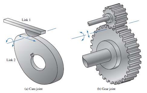
13 Wheel Planar pure-roll (R), pure-slide (P), or roll-slide (RP) joint - 1 or 2 DOF (higher pair) 13

14 14


15 Kinematic pairs (joints) may be classified in several diffrent forms. Classification Mechanisms of Kinematic Pairs Type of contact Closed kinematic form Open kinematic form Lower kinematic pairs Higher kinematic pairs Force closed Form closed Contact along a surface A nut and a bolt have been assembled to each other by its geometry The spring provides contact between the follower and cam. Contact at a point or on a line Closed kinematic pairs are those in which the contact between the kinematic elements is maintained within all possible positions of a mechanism. In force closed kinematic pairs, there exist an external force ( spring force etc.) which keeps the two kinematic elements in contact. In form closed kinematic pairs, one of the kinematic elements envelopes the other. An open kinematic pair is one whose pairing and unpairing of its kinematic elements that form the joint are controlled. 15


16 Degree of freedom of a rigid body: The degree of freedom (DOF) of a rigid body is the number of independent parameters that define its configuration Six independent parameters are required to define the motion of the ship. DOF=6, λ=6 (spatial space) DOF=3, λ=3 (planar space) An unrestrained rigid body in space has six degrees of freedom: three translating motions along the x, y and z axes and three rotary motions around the x, y and z axes respectively. Degree of freedom a kinematic pair: The degrees of freedom (DOF) of a kinemtaic pairs defined as the number of independent movements it has. 16


17 Degree of freedom a kinematic pair: 17

18 Degree of freedom a kinematic pair: Joint with Highest freedom. Translation perpendicular to the plane is restricted. Translations within the plane and rotation in all three axes are possible the ball can rotate around the x,y and z-axes **In force closed kinematic pairs, there exist an external force ( spring force etc.) which keeps the two kinematic elements in contact. **In form closed kinematic pairs, one of the kinematic elements envelopes the other. When a Cylinder is confined between two parallel planes, there is no translation perpendicular to the planes and no rotation about an axis within the plane perpendicular to the cylinder axis. Translation about two perpendicular axes within the plane and rotation about the cylinder axis and about an axes perpendicular to the plane are possible 18

19 Degree of freedom a kinematic pair: Joint with Highest freedom. Translation perpendicular to the plane is restricted. Translations within the plane and rotation in all three axes are possible When a Cylinder is confined between two parallel planes, there is no translation perpendicular to the planes and no rotation about an axis within the plane perpendicular to the cylinder axis. Translation about two perpendicular axes within the plane and rotation about the cylinder axis and about an axes perpendicular to the plane are possible Three axes of rotation intersect at the center of the sphere If a pin perpendicular to the axes of translation is inserted into a slot, then rotation about the translation axis is constrained. If the slot is cut in a different direction, rotation about one axis will be constrained. Translation in two axes (in plane) and rotation (perpendicular to the plane) are possible. Rotation axes are skew (they do not intersect). The rotation and translation axes are coincident Axes of translation and rotation are perpendicular to each other. 19
20 20


21 If a rigid body contains at least two kinematic elements we shall call it a link. A link may have more than two kinematic elements (but not less than two). One can classify links according to the number of kinematic elements it contains. These are binary, ternary or quarternary, etc. For the kinematic analysis we shall be interested only with the kinematic dimensions The kinematic dimensions of a link in a mechanism are those dimensions which define the relative positions of the kinematic elements on that link and when these dimensions are specified, the link dimensions are known for motion analysis. These dimensions can be distances or angles. For the manufacture of the link or for the dynamics, etc other physical dimensions such as the width, height, thickness, etc. may be important. For the kinematic analysis we shall be interested only with the kinematic dimensions. As seen with the above figure, on the link at points A and B kinematic elements form revolute joins, whereas at D there is a cylinder in slot joint. For manufacture besides the thickness, one must specify the radii ( R 1, R 2, R 3 ), the slot length and width (L 1, L 2 ), the length of the piece (L 3 ) etc. These have no importance for kinematics. Whereas the distance between revolute joints A and B (a), the angle slot makes with respect to the line AB (α) and perpendicular distance from point A to the slot axis (b)are the kinematic dimensions of this link. Once these four parameters are known, the link is kinematically defined. 21

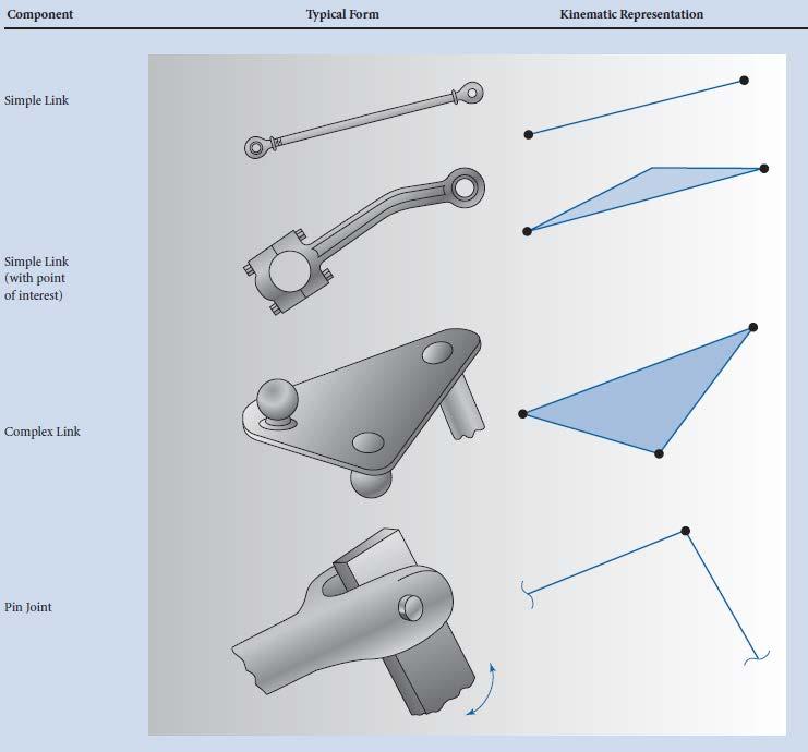
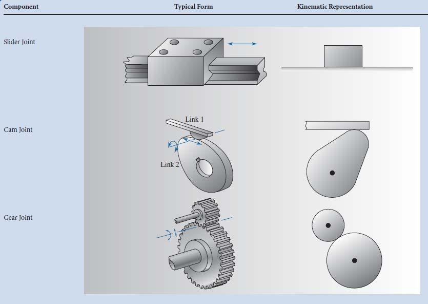
22 Kinematic diagram: A kinematic diagram or kinematic scheme illustrates the connectivity of links and joints of a mechanism or machine rather than the dimensions or shape of the parts. Often links are presented as geometric objects, such as lines, triangles or squares, that support schematic versions of the joints of the mechanism or machine. Connecting rod 22
23 23
24 24

25 Kinematic diagram Crank mechanism Shaping Machine (Quick Return Mechanism) 25
26 There are certain joints where more than two links are connected. For such cases we define the degree-of a joint as the number of links connected at the joint minus one. One must assume that there joints at this point equal to the degree of the joint, ( please do not confuse the degree of the joint with the degree-of-freedom of a joint) Degree of a joint is equal to the number of joints at that connection. Degree of freedom of a joint is the number of independent parameters required to define the position of one link relative to the other connected by that joint. 26

27 Kinematic chain: The links connected to each other by kinematic pairs will form a kinematic chain. If all the kinematic pairs are closed, than we have a closed kinematic chain. If one of the kinematic pair is of open type, the kinematic chain is an open kinematic chain. Kinematic chain is an idealised representation of the mechanism structure. We are not concerned with the dimensions of the links. Each link is represented as a line or as a polygon and at each vertex we have a kinematic element which joins with another element on another link. The dimensions of the edges are not important. Shaping Machine (Quick Return Mechanism) Sled element 1- The kinematic diagram of all links is drawn 2- All links are connected according to their kinematic pairs 1 closed kinematic chain. Slider element

28 open kinematic chain For higher kinematic pair
29 29

30 The degree of freedom of a mechanism (mobility) is the number of independent parameters required to define the position of every link in that mechanism Degree of freedom of a mechanism depends on: The degree of freedom of space The degree of freedom of the joints The number of links and joints The distribution of links and joints Does not depend on the shape of the links. Determination of the Degree-of- Freedom of a Mechanism F j f = λ ( 1) + j i= 1 i *** If F=0 or F<0, the mechnisms can be called static or hiperstatic respectively. 30


31 To increase the load carrying capacity there can be several contact points between the two links. Each contact point cannot be treated as a different kinematic pair. There can be only one kinematic element between two links. There is one kinematic element (lower kinematic pair) between two links. 31

 4")
 = 3( 6 7 1) + 1 1 1 1 1 1 1 = 1")
32 Four-bar linkage = λ ( 1) + F j f j i i= 1 Slider crank mechanism F = 3( 1) + ( ) = i= 1 Shaping Machine (Quick Return Mechanism) F 7 i= 1 ( ) = 3( 6 7 1) = 1 32
 + 8")
 + 13 i= 1 13")
33 Adjustable Drive Grabber Second order pin joints F = 3( 7 8 1) + 8 i= 1 ( ) = 2 F = 3( ) + 13 i= 1 13 = 1 33
34 F 10 = 3( 1) + ( ) = i= 1 34

35 A simplified engineering drawing of the front loader assembly is as shown. Note that a lot of details are neglected. 35

36 The Schematic kinematic diagram of the mechanism involved for the front loader is as shown. Note that each link in practice may be composed of several different rigid bodies that are rigidly connected to each other. F = 3( ) + 12 i= 1 11 = 2 ( ) The two degrees of freedom refer to the displacement parameters between the piston and cylinders. It can be said that two actuators need for the front loader motion 36
WEEK 4 MECHANISMS. References
 References WEEK 4 MECHANISMS (METU, Department of Mechanical Engineering) Text Book: Mechanisms Web Page: http://www.me.metu.edu.tr/people/eres/me301/in dex.ht Analitik Çözümlü Örneklerle Mekanizma Tekniği,
Kinematics of Machines. Brown Hills College of Engineering & Technology
 Introduction: mechanism and machines, kinematic links, kinematic pairs, kinematic chains, plane and space mechanism, kinematic inversion, equivalent linkages, four link planar mechanisms, mobility and
Modelling of mechanical system CREATING OF KINEMATIC CHAINS
 Modelling of mechanical system CREATING OF KINEMATIC CHAINS Mechanism Definitions 1. a system or structure of moving parts that performs some function 2. is each system reciprocally joined moveable bodies
Kinematics Fundamentals CREATING OF KINEMATIC CHAINS
 Kinematics Fundamentals CREATING OF KINEMATIC CHAINS Mechanism Definitions 1. a system or structure of moving parts that performs some function 2. is each system reciprocally joined moveable bodies the
SAMPLE STUDY MATERIAL. Mechanical Engineering. Postal Correspondence Course. Theory of Machines. GATE, IES & PSUs
 TOM - ME GATE, IES, PSU 1 SAMPLE STUDY MATERIAL Mechanical Engineering ME Postal Correspondence Course Theory of Machines GATE, IES & PSUs TOM - ME GATE, IES, PSU 2 C O N T E N T TOPIC 1. MACHANISMS AND
Chapter 4. Mechanism Design and Analysis
 Chapter 4. Mechanism Design and Analysis All mechanical devices containing moving parts are composed of some type of mechanism. A mechanism is a group of links interacting with each other through joints
Theory of Machines Course # 1
 Theory of Machines Course # 1 Ayman Nada Assistant Professor Jazan University, KSA. arobust@tedata.net.eg March 29, 2010 ii Sucess is not coming in a day 1 2 Chapter 1 INTRODUCTION 1.1 Introduction Mechanisms
CHAPTER 1 : KINEMATICS
 KINEMATICS : It relates to the study of the relative motion between the parts of a machine. Let us consider a reciprocating engine, in this the piston is made to reciprocate in the cylinderdue to the applied
ME 321 Kinematics and Dynamics of Machines
 .0 INTRODUCTION ME Kinematics and Dynamics of Machines All Text References in these notes are for: Mechanism Design: Analysis and Synthesis, Volume, Fourth Edition, Erdman, Sandor and Kota, Prentice-Hall,
Chapter 1 Introduction
 Chapter 1 Introduction Generally all considerations in the force analysis of mechanisms, whether static or dynamic, the links are assumed to be rigid. The complexity of the mathematical analysis of mechanisms
September 20, Chapter 5. Simple Mechanisms. Mohammad Suliman Abuhaiba, Ph.D., PE
 Chapter 5 Simple Mechanisms 1 Mohammad Suliman Abuhaiba, Ph.D., PE 2 Assignment #1 All questions at the end of chapter 1 st Exam: Saturday 29/9/2018 3 Kinematic Link or Element kinematic link (link) or
Kinematics: Intro. Kinematics is study of motion
 Kinematics is study of motion Kinematics: Intro Concerned with mechanisms and how they transfer and transform motion Mechanisms can be machines, skeletons, etc. Important for CG since need to animate complex
Analytical and Applied Kinematics
 Analytical and Applied Kinematics Vito Moreno moreno@engr.uconn.edu 860-614-2365 (cell) http://www.engr.uconn.edu/~moreno Office EB1, hours Thursdays 10:00 to 5:00 1 This course introduces a unified and
Lesson 1: Introduction to Pro/MECHANICA Motion
 Lesson 1: Introduction to Pro/MECHANICA Motion 1.1 Overview of the Lesson The purpose of this lesson is to provide you with a brief overview of Pro/MECHANICA Motion, also called Motion in this book. Motion
A rigid body free to move in a reference frame will, in the general case, have complex motion, which is simultaneously a combination of rotation and
 050389 - Analtical Elements of Mechanisms Introduction. Degrees of Freedom he number of degrees of freedom (DOF) of a sstem is equal to the number of independent parameters (measurements) that are needed
Kinematics of Machines Prof. A. K. Mallik Department of Mechanical Engineering Indian Institute of Technology, Kanpur. Module - 3 Lecture - 1
 Kinematics of Machines Prof. A. K. Mallik Department of Mechanical Engineering Indian Institute of Technology, Kanpur Module - 3 Lecture - 1 In an earlier lecture, we have already mentioned that there
COPYRIGHTED MATERIAL INTRODUCTION CHAPTER 1
 CHAPTER 1 INTRODUCTION Modern mechanical and aerospace systems are often very complex and consist of many components interconnected by joints and force elements such as springs, dampers, and actuators.
Position and Displacement Analysis
 Position and Displacement Analysis Introduction: In this chapter we introduce the tools to identifying the position of the different points and links in a given mechanism. Recall that for linkages with
DESIGN AND ANALYSIS OF WEIGHT SHIFT STEERING MECHANISM BASED ON FOUR BAR MECHANISM
 International Journal of Mechanical Engineering and Technology (IJMET) Volume 8, Issue 12, December 2017, pp. 417 424, Article ID: IJMET_08_12_041 Available online at http://www.iaeme.com/ijmet/issues.asp?jtype=ijmet&vtype=8&itype=12
Mechanisms. Updated: 18Apr16 v7
 Mechanisms Updated: 8Apr6 v7 Mechanism Converts input motion or force into a desired output with four combinations of input and output motion Rotational to Oscillating Rotational to Rotational Rotational
2.1 Introduction. 2.2 Degree of Freedom DOF of a rigid body
 Chapter 2 Kinematics 2.1 Introduction 2.2 Degree of Freedom 2.2.1 DOF of a rigid body In order to control and guide the mechanisms to move as we desired, we need to set proper constraints. In order to
MECHANICAL ENGINEERING
 MECHANICAL ENGINEERING ESE TOPICWISE OBJECTIVE SOLVED PAPER-II FROM (1995-2018) UPSC Engineering Services Examination State Engineering Service Examination & Public Sector Examination. IES MASTER PUBLICATION
INTRODUCTION CHAPTER 1
 CHAPTER 1 INTRODUCTION Modern mechanical and aerospace systems are often very complex and consist of many components interconnected by joints and force elements such as springs, dampers, and actuators.
MACHINES AND MECHANISMS
 MACHINES AND MECHANISMS APPLIED KINEMATIC ANALYSIS Fourth Edition David H. Myszka University of Dayton PEARSON ж rentice Hall Pearson Education International Boston Columbus Indianapolis New York San Francisco
KINEMATICS OF MACHINES. Dr.V.SUNDARESWARAN PROFESSOR OF MECHANICAL ENGG. COLLEGE OF ENGINEERING, GUINDY ANNA UNIVERSITY CHENNAI
 KINEMATICS OF MACHINES Dr.V.SUNDARESWARAN PROFESSOR OF MECHANICAL ENGG. COLLEGE OF ENGINEERING, GUINDY ANNA UNIVERSITY CHENNAI 600 025 MECHANICS Science dealing with motion DIVISIONS OF MECHANICS Statics
SolidWorks Assembly Files. Assemblies Mobility. The Mating Game Mating features. Mechanical Mates Relative rotation about axes
 Assemblies Mobility SolidWorks Assembly Files An assembly file is a collection of parts The first part brought into an assembly file is fixed Other parts are constrained relative to that part (or other
Kinematics of Machines Prof. A. K. Mallik Department of Mechanical Engineering Indian Institute of Technology, Kanpur. Module 10 Lecture 1
 Kinematics of Machines Prof. A. K. Mallik Department of Mechanical Engineering Indian Institute of Technology, Kanpur Module 10 Lecture 1 So far, in this course we have discussed planar linkages, which
2.007 Design and Manufacturing I Spring 2009
 MIT OpenCourseWare http://ocw.mit.edu 2.007 Design and Manufacturing I Spring 2009 For information about citing these materials or our Terms of Use, visit: http://ocw.mit.edu/terms. 2.007 Design and Manufacturing
NOT COMPLETE. θ 4 B 2 = O 2 O 4 = A 2 = A 1 B 1 O 2 KINEMATIC SYNTHESIS
 ME 35 NOT COMPLETE Design Design a crank-rocker four-bar (Grashof) where the input link rotates completely and the output link (the follower) rocks back and forth with a prescribed angle The design requires
Lecture 3. Planar Kinematics
 Matthew T. Mason Mechanics of Manipulation Outline Where are we? s 1. Foundations and general concepts. 2.. 3. Spherical and spatial kinematics. Readings etc. The text: By now you should have read Chapter
Overview. What is mechanism? What will I learn today? ME 311: Dynamics of Machines and Mechanisms Lecture 2: Synthesis
 Overview ME 311: Dynamics of Machines and Mechanisms Lecture 2: Synthesis By Suril Shah Some fundamentals Synthesis Function, path and motion generation Limiting condition Dimensional synthesis 1 2 What
Position Analysis
 Position Analysis 2015-03-02 Position REVISION The position of a point in the plane can be defined by the use of a position vector Cartesian coordinates Polar coordinates Each form is directly convertible
Mechanics Place in Science Mechanisms and Structures Number Synthesis Paradoxes and Isomers Transformations and Inversions Grashof s Law
 INTODUCTION TO MECHANISM SYNTHESIS Mechanics Place in Science Mechanisms and Structures Number Synthesis Paradoxes and Isomers Transformations and Inversions Grashof s Law ME312: Dynamics of Mechanisms
Kinematics of Machines Prof. A. K. Mallik Department of Mechanical Engineering Indian Institute of Technology, Kanpur. Module - 2 Lecture - 1
 Kinematics of Machines Prof. A. K. Mallik Department of Mechanical Engineering Indian Institute of Technology, Kanpur Module - 2 Lecture - 1 The topic of today s lecture is mobility analysis. By mobility
Solutions to Chapter 6 Exercise Problems A 1 O 4 B 2
 Solutions to Chapter 6 Exercise Problems Problem 6.1: Design a double rocker, four-bar linkage so that the base link is 2-in and the output rocker is 1-in long. The input link turns counterclockwise 60
PROBLEMS AND EXERCISES PROBLEMS
 64 Fundamentals of Kinematics and Dynamics of Machines and Mechanisms PROBLEMS AND EXERCISES PROBLEMS 1. In Figure 1.14c an inverted slider-crank mechanism is shown. b. If the input is the displacement
10/25/2018. Robotics and automation. Dr. Ibrahim Al-Naimi. Chapter two. Introduction To Robot Manipulators
 Robotics and automation Dr. Ibrahim Al-Naimi Chapter two Introduction To Robot Manipulators 1 Robotic Industrial Manipulators A robot manipulator is an electronically controlled mechanism, consisting of
The Design and Simulation of Mechanisms. Inna Sharifgalieva
 The Design and Simulation of Mechanisms Inna Sharifgalieva Degree Thesis Degree Programme: Materials Processing Technology 2014 2018 1 DEGREE THESIS Arcada University of Applied Sciences Degree Programme:
3. Manipulator Kinematics. Division of Electronic Engineering Prof. Jaebyung Park
 3. Manipulator Kinematics Division of Electronic Engineering Prof. Jaebyung Park Introduction Kinematics Kinematics is the science of motion which treats motion without regard to the forces that cause
Connection Elements and Connection Library
 Connection Elements and Connection Library Lecture 2 L2.2 Overview Introduction Defining Connector Elements Understanding Connector Sections Understanding Connection Types Understanding Connector Local
MACHINE THEORY Bachelor in Mechanical Engineering INTRODUCTION TO MACHINE DESIGN
 MACHINE THEORY Bachelor in Mechanical Engineering INTRODUCTION TO MACHINE DESIGN Ignacio Valiente Blanco José Luis Pérez Díaz David Mauricio Alba Lucero Efrén Díez Jiménez Timm Lauri Berit Sanders Machine
[3] Rigid Body Analysis
![[3] Rigid Body Analysis](/thumbs/92/109073357.jpg "[3] Rigid Body Analysis") [3] Rigid Body Analysis Page 1 of 53 [3] Rigid Body Analysis [3.1] Equilibrium of a Rigid Body [3.2] Equations of Equilibrium [3.3] Equilibrium in 3-D [3.4] Simple Trusses [3.5] The Method of Joints [3.6]
[3] Rigid Body Analysis Page 1 of 53 [3] Rigid Body Analysis [3.1] Equilibrium of a Rigid Body [3.2] Equations of Equilibrium [3.3] Equilibrium in 3-D [3.4] Simple Trusses [3.5] The Method of Joints [3.6]
Mechanism Kinematics and Dynamics
 Mechanism Kinematics and Dynamics Final Project 1. The window shield wiper For the window wiper, (1). Select the length of all links such that the wiper tip X p (t) can cover a 120 cm window width. (2).
Lecture Note 2: Configuration Space
 ECE5463: Introduction to Robotics Lecture Note 2: Configuration Space Prof. Wei Zhang Department of Electrical and Computer Engineering Ohio State University Columbus, Ohio, USA Spring 2018 Lecture 2 (ECE5463
Human Motion. Session Speaker Dr. M. D. Deshpande. AML2506 Biomechanics and Flow Simulation PEMP-AML2506
 AML2506 Biomechanics and Flow Simulation Day 02A Kinematic Concepts for Analyzing Human Motion Session Speaker Dr. M. D. Deshpande 1 Session Objectives At the end of this session the delegate would have
Model Library Mechanics
 Model Library Mechanics Using the libraries Mechanics 1D (Linear), Mechanics 1D (Rotary), Modal System incl. ANSYS interface, and MBS Mechanics (3D) incl. CAD import via STL and the additional options
Homework 4 PROBLEMS ON THREE POSITION GUIDANCE
 Homework 4 ROLEMS ON THREE OSITION GUIDNE. In the synthesis of three positions of a plane by a four-bar mechanism, in the graphical method and were selected arbitrarily and, were determined as the corresponding
MENG 372 Chapter 3 Graphical Linkage Synthesis. All figures taken from Design of Machinery, 3 rd ed. Robert Norton 2003
 MENG 372 Chapter 3 Graphical Linkage Synthesis All figures taken from Design of Machinery, 3 rd ed. Robert Norton 2003 1 Introduction Synthesis: to design or create a mechanism to give a certain motion
Robotics. SAAST Robotics Robot Arms
 SAAST Robotics 008 Robot Arms Vijay Kumar Professor of Mechanical Engineering and Applied Mechanics and Professor of Computer and Information Science University of Pennsylvania Topics Types of robot arms
Kinematic Synthesis. October 6, 2015 Mark Plecnik
 Kinematic Synthesis October 6, 2015 Mark Plecnik Classifying Mechanisms Several dichotomies Serial and Parallel Few DOFS and Many DOFS Planar/Spherical and Spatial Rigid and Compliant Mechanism Trade-offs
Mechanism Design. Four-bar coupler-point curves
 Mechanism Design Four-bar coupler-point curves Four-bar coupler-point curves A coupler is the most interesting link in any linkage. It is in complex motion, and thus points on the coupler can have path
Motion Simulation and Mechanism Design with SOLIDWORKS Motion 2017
 Motion Simulation and Mechanism Design with SOLIDWORKS Motion 2017 Kuang-Hua Chang Ph.D. SDC P U B L I C AT I O N S Better Textbooks. Lower Prices. www.sdcpublications.com Powered by TCPDF (www.tcpdf.org)
OPTIMAL KINEMATIC DESIGN OF A CAR AXLE GUIDING MECHANISM IN MBS SOFTWARE ENVIRONMENT
 OPTIMAL KINEMATIC DESIGN OF A CAR AXLE GUIDING MECHANISM IN MBS SOFTWARE ENVIRONMENT Dr. eng. Cătălin ALEXANDRU Transilvania University of Braşov, calex@unitbv.ro Abstract: This work deals with the optimal
Session #5 2D Mechanisms: Mobility, Kinematic Analysis & Synthesis
 Session #5 2D Mechanisms: Mobility, Kinematic Analysis & Synthesis Courtesy of Design Simulation Technologies, Inc. Used with permission. Dan Frey Today s Agenda Collect assignment #2 Begin mechanisms
Mechanism Kinematics and Dynamics
 Mechanism Kinematics and Dynamics Final Project Presentation 10:10-13:00, 12/21 and 12/28 1. The window shield wiper (2) For the window wiper in Fig.1.33 on p.26 of the PPT, (1). Select the length of all
Engineering Mechanics. Equilibrium of Rigid Bodies
 Engineering Mechanics Equilibrium of Rigid Bodies System is in equilibrium if and only if the sum of all the forces and moment (about any point) equals zero. Equilibrium Supports and Equilibrium Any structure
Basilio Bona ROBOTICA 03CFIOR 1
 Kinematic chains 1 Readings & prerequisites Chapter 2 (prerequisites) Reference systems Vectors Matrices Rotations, translations, roto-translations Homogeneous representation of vectors and matrices Chapter
Industrial Robots : Manipulators, Kinematics, Dynamics
 Industrial Robots : Manipulators, Kinematics, Dynamics z z y x z y x z y y x x In Industrial terms Robot Manipulators The study of robot manipulators involves dealing with the positions and orientations
UNDERSTANDING MOTION SIMULATION
 W H I T E P A P E R UNDERSTANDING MOTION SIMULATION Overview What is motion simulation? What problems can it solve? How can it benefit the product design process? This paper addresses some of these issues
Structural synthesis of linkages for quadruped biorobot
 IOP onference Series: Materials Science and Engineering PAPER OPE AESS Structural synthesis of linkages for quadruped biorobot legs To cite this article: O Antonescu et al 16 IOP onf. Ser.: Mater. Sci.
Understanding Motion Simulation
 white paper Understanding Motion Simulation inspiration SUMMARY What is motion simulation? What problems can it solve? How can it benefit the product design process? This paper addresses some of these
Kinematics - Introduction. Robotics. Kinematics - Introduction. Vladimír Smutný
 Kinematics - Introduction Robotics Kinematics - Introduction Vladimír Smutný Center for Machine Perception Czech Institute for Informatics, Robotics, and Cybernetics (CIIRC) Czech Technical University
Simulation Model for Coupler Curve Generation using Five Bar Planar Mechanism With Rotation Constraint
 Simulation Model for Coupler Curve Generation using Five Bar Planar Mechanism With Rotation Constraint A. K. Abhyankar, S.Y.Gajjal Department of Mechanical Engineering, NBN Sinhgad School of Engineering,
Cam makes a higher kinematic pair with follower. Cam mechanisms are widely used because with them, different types of motion can be possible.
 CAM MECHANISMS Cam makes a higher kinematic pair with follower. Cam mechanisms are widely used because with them, different types of motion can be possible. Cams can provide unusual and irregular motions
1. Introduction 1 2. Mathematical Representation of Robots
 1. Introduction 1 1.1 Introduction 1 1.2 Brief History 1 1.3 Types of Robots 7 1.4 Technology of Robots 9 1.5 Basic Principles in Robotics 12 1.6 Notation 15 1.7 Symbolic Computation and Numerical Analysis
MAE 342 Dynamics of Machines. Types of Mechanisms. type and mobility
 MAE 342 Dynamics of Machines Types of Mechanisms Classification of Mechanisms by type and mobility MAE 342 Dynamics of Machines 2 Planar, Spherical and Spatial Mechanisms Planar Mechanisms: all points
Introduction to Solid Modeling Using SolidWorks 2008 COSMOSMotion Tutorial Page 1
 Introduction to Solid Modeling Using SolidWorks 2008 COSMOSMotion Tutorial Page 1 In this tutorial, we will learn the basics of performing motion analysis using COSMOSMotion. Although the tutorial can
This week. CENG 732 Computer Animation. Warping an Object. Warping an Object. 2D Grid Deformation. Warping an Object.
 CENG 732 Computer Animation Spring 2006-2007 Week 4 Shape Deformation Animating Articulated Structures: Forward Kinematics/Inverse Kinematics This week Shape Deformation FFD: Free Form Deformation Hierarchical
ROBOTICS 01PEEQW. Basilio Bona DAUIN Politecnico di Torino
 ROBOTICS 01PEEQW Basilio Bona DAUIN Politecnico di Torino Kinematic chains Readings & prerequisites From the MSMS course one shall already be familiar with Reference systems and transformations Vectors
ROSE-HULMAN INSTITUTE OF TECHNOLOGY
 Introduction to Working Model Welcome to Working Model! What is Working Model? It's an advanced 2-dimensional motion simulation package with sophisticated editing capabilities. It allows you to build and
Chapter 4: Kinematics of Rigid Bodies
 Chapter 4: Kinematics of Rigid Bodies Advanced Dynamics Lecturer: Hossein Nejat Fall 2016 A rigid body is defined to be a collection of particles whose distance of separation is invariant. In this circumstance,
What s inside your experiment kit: Checklist: Find Inspect Check off KIT CONTENTS. GOOD TO KNOW! If you are missing any. No. Description Qty. Item No.
 EXPERIMENT MANUAL Franckh-Kosmos Verlags-GmbH & Co. KG, Pfizerstr. 5-7, 7084 Stuttgart, Germany +49 (0) 7 29-0 www.kosmos.de Thames & Kosmos, 30 Friendship St., Providence, RI, 02903, USA -800-587-2872
Manipulator Path Control : Path Planning, Dynamic Trajectory and Control Analysis
 Manipulator Path Control : Path Planning, Dynamic Trajectory and Control Analysis Motion planning for industrial manipulators is a challenging task when obstacles are present in the workspace so that collision-free
Mechanism Synthesis Rules
 Mechanism Synthesis ules Linkage Transformation ules Grashof s Law Inversion ME312: Dynamics of Mechanisms 1 BB LINKAGE TANSFOMATION ULE 1 evolute joints in any loop can be replaced by prismatic joints
A survey paper on a factors affecting on selection of mechanical gripper
 2014 IJEDR Volume 2, Issue 1 ISSN: 2321-9939 A survey paper on a factors affecting on selection of mechanical gripper 1 Vinayak D. Latake, 2 Dr. V.M.Phalle 1 PG Scholar, 2 AssociateProfessor Department
DYNAMICS MODELING OF A POWER TRANSMISSION MECHANISM WITH LINKAGE AND INERTIAL MASS
 FACULTY OF MCHANICS AND TCHNOLOGY SCINTIFIC BULLTIN AUTOMOTIV series, ear XIX, no. B DYNAMICS MODLING OF A POWR TRANSMISSION MCHANISM WITH LINKAG AND INRTIAL MASS Ion ION-GUTA Universit of Pitesti, Romania,
Week 12 - Lecture Mechanical Event Simulation. ME Introduction to CAD/CAE Tools
 Week 12 - Lecture Mechanical Event Simulation Lecture Topics Mechanical Event Simulation Overview Additional Element Types Joint Component Description General Constraint Refresh Mesh Control Force Estimation
Mechanism Synthesis. Introduction: Design of a slider-crank mechanism
 Mechanism Synthesis Introduction: Mechanism synthesis is the procedure by which upon identification of the desired motion a specific mechanism (synthesis type), and appropriate dimensions of the linkages
SimWise. 3D Dynamic Motion, and Stress Analysis. integrated with Alibre Design
 SimWise 3D Dynamic Motion, and Stress Analysis integrated with Alibre Design SimWise 4D for Alibre Integrated Motion Simulation and Stress Analysis SimWise 4D is a software tool that allows the functional
Mechanism. Mechanism consists of linkages and joints.
 Mechanism Machines are mechanical devices used to accomplish work. A mechanism is a heart of a machine. It is the mechanical portion of the machine that has the function of transferring motion and forces
Robotics Prof. Dilip Kumar Pratihar Department of Mechanical Engineering Indian Institute of Technology, Kharagpur
 Robotics Prof. Dilip Kumar Pratihar Department of Mechanical Engineering Indian Institute of Technology, Kharagpur Lecture 03 Introduction to Robot and Robotics (Contd.) (Refer Slide Time: 00:34) Now,
Forward kinematics and Denavit Hartenburg convention
 Forward kinematics and Denavit Hartenburg convention Prof. Enver Tatlicioglu Department of Electrical & Electronics Engineering Izmir Institute of Technology Chapter 5 Dr. Tatlicioglu (EEE@IYTE) EE463
KINEMATICS OF AN OVERCONSTRAINED MECHANISM IN PRACTICE
 KINEMTICS OF N OVERCONSTRINED MECHNISM IN PRCTICE Vandan Kamlakar Gundale* bstract: In 1939 Paul Schatz, a Swiss anthroposophist and geometrician had invented a mechanism which with few links generates
Spatial R-C-C-R Mechanism for a Single DOF Gripper
 NaCoMM-2009-ASMRL28 Spatial R-C-C-R Mechanism for a Single DOF Gripper Rajeev Lochana C.G * Mechanical Engineering Department Indian Institute of Technology Delhi, New Delhi, India * Email: rajeev@ar-cad.com
Chapter 5 Modeling and Simulation of Mechanism
 Chapter 5 Modeling and Simulation of Mechanism In the present study, KED analysis of four bar planar mechanism using MATLAB program and ANSYS software has been carried out. The analysis has also been carried
2. Motion Analysis - Sim-Mechanics
 2 Motion Analysis - Sim-Mechanics Figure 1 - The RR manipulator frames The following table tabulates the summary of different types of analysis that is performed for the RR manipulator introduced in the
1.9 Snap Action Mechanisms 19
 Theory of Mechanism and Machines Chapter- Introduction Prepared y rij hooshan sst. Professor. S.. College of Engg. nd Technology Mathura, Uttar Pradesh, (India) Supported y: Purvi hooshan In This Chapter
A simple example. Assume we want to find the change in the rotation angles to get the end effector to G. Effect of changing s
 CENG 732 Computer Animation This week Inverse Kinematics (continued) Rigid Body Simulation Bodies in free fall Bodies in contact Spring 2006-2007 Week 5 Inverse Kinematics Physically Based Rigid Body Simulation
ME 115(b): Final Exam, Spring
: Final Exam, Spring") ME 115(b): Final Exam, Spring 2005-06 Instructions 1. Limit your total time to 5 hours. That is, it is okay to take a break in the middle of the exam if you need to ask me a question, or go to dinner,
ME 115(b): Final Exam, Spring 2005-06 Instructions 1. Limit your total time to 5 hours. That is, it is okay to take a break in the middle of the exam if you need to ask me a question, or go to dinner,
COSMOS. Understanding Motion Simulation ---- SolidWorks Corporation. Introduction 1. Motion simulation for mechanism analysis and synthesis 1-6
 ---- WHITE PAPER Understanding Motion Simulation CONTENTS Introduction 1 Motion simulation for mechanism analysis and synthesis 1-6 Using motion simulation along with FEA 6-9 Motion simulation and test
Structural Configurations of Manipulators
 Structural Configurations of Manipulators 1 In this homework, I have given information about the basic structural configurations of the manipulators with the concerned illustrations. 1) The Manipulator
Design of a Three-Axis Rotary Platform
 Design of a Three-Axis Rotary Platform William Mendez, Yuniesky Rodriguez, Lee Brady, Sabri Tosunoglu Mechanics and Materials Engineering, Florida International University 10555 W Flagler Street, Miami,
ME 111: Engineering Drawing. Geometric Constructions
 ME 111: Engineering Drawing Lecture 2 01-08-2011 Geometric Constructions Indian Institute of Technology Guwahati Guwahati 781039 Geometric Construction Construction of primitive geometric forms (points,
Lecture Note 2: Configuration Space
 ECE5463: Introduction to Robotics Lecture Note 2: Configuration Space Prof. Wei Zhang Department of Electrical and Computer Engineering Ohio State University Columbus, Ohio, USA Spring 2018 Lecture 2 (ECE5463
Using RecurDyn. Contents
 Using RecurDyn Contents 1.0 Multibody Dynamics Overview... 2 2.0 Multibody Dynamics Applications... 3 3.0 What is RecurDyn and how is it different?... 4 4.0 Types of RecurDyn Analysis... 5 5.0 MBD Simulation
MC-E - Motion Control
 IDC Technologies - Books - 1031 Wellington Street West Perth WA 6005 Phone: +61 8 9321 1702 - Email: books@idconline.com MC-E - Motion Control Price: $139.94 Ex Tax: $127.22 Short Description This manual
AC : AN ALTERNATIVE APPROACH FOR TEACHING MULTIBODY DYNAMICS
 AC 2009-575: AN ALTERNATIVE APPROACH FOR TEACHING MULTIBODY DYNAMICS George Sutherland, Rochester Institute of Technology DR. GEORGE H. SUTHERLAND is a professor in the Manufacturing & Mechanical Engineering
CHAPTER 3 MATHEMATICAL MODEL
 38 CHAPTER 3 MATHEMATICAL MODEL 3.1 KINEMATIC MODEL 3.1.1 Introduction The kinematic model of a mobile robot, represented by a set of equations, allows estimation of the robot s evolution on its trajectory,
Dynamics Analysis for a 3-PRS Spatial Parallel Manipulator-Wearable Haptic Thimble
 Dynamics Analysis for a 3-PRS Spatial Parallel Manipulator-Wearable Haptic Thimble Masoud Moeini, University of Hamburg, Oct 216 [Wearable Haptic Thimble,A Developing Guide and Tutorial,Francesco Chinello]
METR 4202: Advanced Control & Robotics
 Position & Orientation & State t home with Homogenous Transformations METR 4202: dvanced Control & Robotics Drs Surya Singh, Paul Pounds, and Hanna Kurniawati Lecture # 2 July 30, 2012 metr4202@itee.uq.edu.au