A Strain Free Lock and Release Mechanism for an Elastically Suspended Two-Axis Gimbal
|
|
|
- Jessie McCormick
- 6 years ago
- Views:
Transcription
1 A Strain Free Lock and Release Mechanism for an Elastically Suspended Two-Axis Gimbal Armond Asadurian Moog Inc., Chatsworth Operations, Nordhoff Street, Chatsworth, CA Tel: Fax: Abstract A single-point-actuated, multi degree-of-freedom restraining launch latch mechanism was developed for a two-degree of freedom tilt table antenna gimbal. The design of the launch latch protects the gimbal pivots and actuators through launch vibration, and precludes any high forces on sensitive gimbal components as a result of operation of the latch mechanism itself. At the same time, stringent requirements on stiffness for the latched gimbal and payload are met. The launch latch design was carried through to qualification largely as initially conceived; however, detail design changes and improvements were made during development as a result of prototyping and development testing. Introduction Both the structure and the actuation paths of efficiently designed spaceflight mechanisms are typically not sized to carry the inertial loads generated by launch vibration acting on the mechanism payload. When this is the case, additional structural load paths are required during the launch phase. Subsequently, the structure so introduced must be removable on command to allow normal on-orbit operation of the mechanism. Mechanism payloads typically are articulated in one or two degrees of freedom (although there can be more), and constrained otherwise by the mechanism joints. If the mechanism power sources are capable of position holding in the launch phase, usually power off, then the phase of the mechanism is nominally fixed. The launch lock device then must support that mechanism configuration with parallel load paths, which are adequately sized for launch loads; so that no damage or degradation of the structure, links, or bearings occurs during launch. Addition of redundant parallel load paths to a completed mechanism creates concern that local overloading of mechanism elements by the simple act of engaging the locking device could occur. This is a primary design driver for the locking device itself. Stiffness parameters of the locking device elements must be tailored in such a way as to avoid high loads in cross-axis directions when the lock is engaged. Functionally, launch latches vary from a simple single degree of freedom constraint (e.g. pin joint), to more complex multiple degree of freedom restraints, depending on payload size and mass and other requirements. The subject of this paper is a clampingtype launch latch, which fully restrains the payload. Launch Latch Requirements The gimbal actuators control the output platform angular orientation actively in the power-on condition and maintain it passively in the power-off condition. However, in the launch phase of the mission, both stiffness and load carrying capability must be enhanced in all six degrees of freedom. For this application, a launch latch has been designed integral to the main gimbal pivot. The specific design requirements for the launch latch are as follows. Stiffness: ~50% increase in gimbal natural frequency over unlocked configuration. Interface Parallelism: ±TBD between mounting I/F plate and payload I/F plate Life: 1 on-orbit unlatch + 50 latch/unlatch cycles during pre-flight testing Reliability: Single fault tolerant electrical operation Status Indication: Position sensing must provide feedback for latched/un-latched mechanism status. Environment: 1200g shock, 30g sine vibration, 26grms random vibration Operations: Mechanism must be re-settable with a quantifiably controlled preload Launch Latch Design The Antenna Pointing Mechanism (APM) two-axis gimbal is a tilt-table gimbal operable in two degrees of freedom. It consists of an output platform mounted on a center pivot, tilted in two axes by orthogonal linear actuators articulated between the output platform and a 1
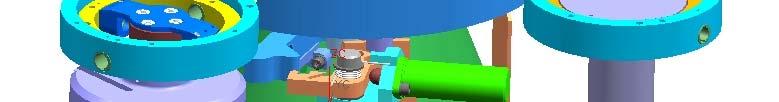
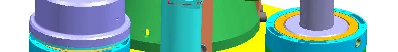
2 similarly shaped base plate which mounts the assembly to the spacecraft. The center pivot is a two degree-offreedom assembly of elastic flex pivots configured as a Cardan joint. Angular range of the elastic flex pivots is sufficient to support the gimbal motion. The gimbal is designed to minimize required envelope, which results in a derived requirement for compact design of the latch mechanism to fit in the available space between the center pivot assembly and the two linear actuators. The requirement for pre-launch access to reset the mechanism results in challenging ergonomic and for packaging the constraints. (See Figure 1) The launch latch mechanism is designed to rigidize and strengthen the center pivot of the tilt table gimbal. Its function is to tie the gimbal output platform directly to fixed structure through four spring beam members arrayed in a circular pattern surrounding the center pivot. The stiffness of the launch latch members protects the center pivot, and the combination of the center pivot suspension and the launch latch is sufficiently stiff to prevent damaging loads from being transferred to the linear actuators. (See Figure 2) The operational range of the gimbal is from 3 to 5 deg of tilt on each axis. Therefore, displacement of the gimbal output plate is relatively small near the pivot. The launch latch mechanism is located near the pivot, so that the motion of the restraining members upon release can be small, while accommodating the operational envelope of the gimbal output plate. The potential for overstressing of the elastic suspension members of the center pivot exists. Avoiding this potential problem is a key issue addressed in the design of the launch latch. Four pins on the underside of the gimbal top platform are engaged by spring beam members when the launch latch is engaged. The spring beam members move radially outward to engage the pins, generating a symmetrical set of radial forces which have no net resultant force on the center pivot assembly. A rotating ring guided by the center pivot assembly Rotation of the ring produces two orthogonal sets of equal opposing forces, and no net lateral reaction on the center pivot. (See Figure 3) Engagement of the rotating ring member with the pins and beams is a manual function. Rotation of the ring moves its rollers into contact with the ramp faces of the spring beams, moving the beams outward by cam action. The outer faces of the spring beams contact the locking pins, and the spring beams are captured and compressed between the rollers and the locking pins. When all parts are fully engaged, the ring is secured by a latch mechanism, which holds it in position. The gimbal then stays in the latched configuration until the ring is released by an Unlatch command. The Unlatch command extends the plunger of a hot wax actuator, releasing the ring latch and freeing the gimbal. Latched Position The ring, the member designed for manual rotation to the latched position, is equipped with four roller assemblies. Each roller assembly is positioned to engage an adjacent spring member and locking pin. As the ring is manually rotated, the roller assemblies simultaneously contact the spring beams and deflect them outward toward the locking pins. Once contact is made between the spring beam and the locking pin, an integral spring establishes the desired preload in the joint. The ring continues to rotate until its arm engages a locking pawl, which latches it in the launch latched position. (See Figure 3) Preload Latching Point The deflection of the preload spring feature is limited to prevent oscillation of the spring under vibration. The preload spring bottoms on a stop, with its further deflection due to higher loads (higher than the preload) prevented. The stop is formed by an adjustable set screw in one arm of the spring member. The latched position and the preloads on the locking pins are established when the arm on the rotating ring engages the locking pawl. The locking pawl rotates on a fixed pivot. Its engagement with the arm on the locking ring is so configured that the line of action of the contact force passes through the pawl pivot, and no component of that force tends to unlatch the pawl. The mechanism is self-locking until released by the Unlatch command. (See Figure 4) Unlatched Position Unlatching occurs when the hot wax motor output is extended on command. The force exerted on the pawl by the actuator rotates the pawl out of the latched position. The torque exerted is adequate to overcome the contact friction between the pawl and the locking ring arm and releases the pawl from the ring. The torque component of the roller-to-spring beam preload forces causes the ring to rotate out of the latched position, and the ring then rotates back to its original unlatched position. (See Figure 5) 2
3 Trigger Mechanism The launch latch assembly is accessible from one side of the gimbal (Fig.1). The arm on the locking ring is oriented for access from the side, and is configured with a threaded receptacle. Resetting is accomplished by installing a resetting tool in the receptacle and rotating the ring to the latched position. The trigger mechanism consists of the wax actuator, the locking pawl, and the latch arm (integral with the rotating ring). A manual input force is exerted on the latch to rotate the ring, allowing the locking pawl to engage the latch and prevent rotation of the ring. The locking arm pawl engagement is maintained by the preload applied at the contact point between the locking pawl and the ring. This preload is due to the lateral components of the forces at the spring beam-to-roller contacts, and the resulting torque on the ring. A torsional spring is used to return the pawl to its latched position, regardless of the orientation of the ring. Release of the latch is initiated by applying power to the wax actuator. The actuator output rod extends, contacting the locking pawl as shown in the figure below, and inducing a torque on the locking pawl to release it from the latch arm. With the locking pawl rotated away from the latch arm, the ring is free to rotate and relieve the preload on the locking pins. (See Figure 5 & 6) Development and Testing Development test hardware was constructed to prove out the launch latch design. The test hardware was designed to simulate the main gimbal pivot and the launch latch mechanism. On one gimbal axis, a previously built linear actuator was used to simulate the mass and CG location of the flight actuator, for accurate system dynamic simulation and also for the capability of tilting the platform on that axis in subsequent testing. An articulated dummy link, again simulating the mass and CG location of the flight actuator, was used in the orthogonal location of the second actuator. The launch lock mechanism moving parts were free of any wet lubricant, to prevent contamination of the payload, and sliding surfaces were coated with Tiolube 1175 dry lubricant. Dicronite dry lubricant was used in the rollers for the launch latch to reduce sliding friction in the mechanism during engagement. The payload mass and center of gravity location were simulated by tooling as shown in the figure to provide a valid configuration for dynamic testing (i.e. shock, random vibration, and sine vibration). (See Figure 7) Lessons Learned Lessons learned in the development of the launch latch mechanism involved issues of materials compatibility, linkage design, optimization, ergonomics, and structured optimization. The resulting design changes were incorporated in the development test unit. (See Figure 8) Material and Surface Compatibility. The launch latch design is not friction-based, and sliding contact of heavily loaded members is generally avoided. However, some sliding contact does occur. Titanium is used as the basic material in the latch mechanism, chosen for its low weight and high stiffness. The surface properties of titanium are not ideal for highly stressed or sliding contacts, and therefore surface modification through anodic coatings and lubricant films was pursued. Tiodize surface conversion treatment and Tiolube lubricant films were used. The highest contact forces occur between the spring beam and the locking pin and between the roller and the spring beam. With the original untreated parts, some galling was observed at these interfaces. After the surface treatment of the titanium spring beam and roller, no further galling occurred. Latch Design: A perceived problem with the locking ring arose during development testing. Although the locking ring is loosely suspended on the center pivot base, and the bearing surfaces are dry film-lubricated, the simple large size of the bearing led to the concern that the locking ring might be prevented by friction from reaching its full unlatched position. This possibility was addressed both by the application of dry film lubrication to the locking ring bearings surfaces, and to the addition of a secondary cam surface to the pivoting latch pawl. After triggering of the unlatching functionand after the high force demand on the hot wax actuator- continued travel of the pivoting pawl engages the cam surface with a mating follower ramp on the arm of the locking ring, insuring its full travel. Latch/Reset Force: During development testing, the force required to reset the latch mechanism was found to be undesirably high from the standpoint of operator ergonomics. Operator effort was reduced, and adequate latched stiffness preserved, by modifying the width and thickness of the spring beam members. Upper Plate Deformation: Bending of the upper plate, or output member, of the gimbal was observed in testing, as a result of the high forces applied to the locking pins by the latch mechanism. Design changes to the plate were made to 3
4 increase stiffness at the locking pin mounting points, and this change eliminated plate bending as a problem. Latch Point Engagement: Because of manufacturing tolerances and the curved motion of the spring beams, some dimensional allowance must be made at the beam-to-latch pin contact point. In the initial design, the allowance was generous, and the holding ability of the latch in the Z direction was augmented by frictional forces. In fact, mating surfaces were textured by grit blasting in order to enhance friction. It was found in testing that texturing actually aggravated galling of the mating surfaces, and that design feature was deleted. Smooth surfaces were used instead, with surface treatment for hardening. Tolerances were tightened, and it was then possible to reduce the dimension of the pocket in the spring beam in which the locking pin seats. The upper and lower shoulders of the pocket offer positive restraint of the locking pin which is not dependent on friction. Conclusion It was found possible to design an effective gimbal launch latch for a very restricted space. Rather than maximizing the radius of action or the length of the lever arms from the gimbal articulation point to the points of fixity, the arm were kept tot a minimum. The restraints, rather than being simple point restraints, are multi-axis lengths clamp points with a higher degree of restraint. The possibility of generating high loads and overstressing the protected structure is avoided by design of the clamping mechanism to accommodate the strength and stiffness properties of the gimbal. A single release point for the multi-point latch mechanism maximizes simplicity and reliability, and also meets operational access and ergonomics criteria. The concept has growth potential to cover larger diameters and heavier payloads. 4

5 Antenna Pointing Mechanism Figure 1 Outer Gimbal Ring Roller Locking Pin Locking Ring Base HED Spring Beams Exploded View of Gimbal and Launch Latch Figure 2 5
6 Locking Pawl Wax Actuator Locking Ring Arm Locking Pin Figure 3 Roller Ring Figure 3 6


7 Locking Pin Setscrew Roller Locking Pin Roller Ring Latched Position Unlatched Position Pin Engagement Pocket Roller Ramp Figure 4 7

8 Roller Locking Pawl Locking Ring Arm Wax Actuator Locking Pin Ring Figure 5 8

9 Roller Locking Pawl Locking Ring Arm Wax Actuator Locking Pin Ring Figure 6 9


10 Sub-reflector dummy mass Linear Actuator Dummy Y-axis actuator used for ETU testing Figure 7 10
11 Titanium Nitride and Tiolube 1175 coating Roller (Tiolube 1175) Figure 8 11
THRUSTER ORIENTATION MECHANISM. Sami Mankaï
 THRUSTER ORIENTATION MECHANISM Sami Mankaï Alcatel space industries 100 Boulevard du Midi, BP 99-06156 Cannes la Bocca Cedex Telephone : 33-(0)4-92-92-79-76 / Fax : 33-(0)4-92-92-60-20 E-mail : sami.mankai@space.alcatel.fr
Deployment and Latching Simulation of Large Reflectors
 Deployment and Latching Simulation of Large Reflectors Sidharth Tiwary [1], B. Lakshmi Narayana [1], B.P. Nagaraj [1], G. Nagesh [2] and C.D. Sridhara [3] [1] Engineer, SMG [2] Project Director, Chandrayaan-2,
DEVELOPMENT OF THE JEM ICS ANTENNA POINTING SYSTEM
 DEVELOPMENT OF THE JEM ICS ANTENNA POINTING SYSTEM Author: Jess Stevenson, Manager, Mechanical Engineering (SMD) MOOG Schaeffer Magnetics Division (SMD) 21339 Nordhoff St., Chatsworth, CA 91311 (818)341-5156,
Principles of Kinematic Constraint
 Principles of Kinematic Constraint For holding a body (rigid thing) with the highest precision, we require: Full 6 DoF constraint If 6 DoFs not fully constrained, then one is loose. No overconstraint Any
SAMPLE STUDY MATERIAL. Mechanical Engineering. Postal Correspondence Course. Theory of Machines. GATE, IES & PSUs
 TOM - ME GATE, IES, PSU 1 SAMPLE STUDY MATERIAL Mechanical Engineering ME Postal Correspondence Course Theory of Machines GATE, IES & PSUs TOM - ME GATE, IES, PSU 2 C O N T E N T TOPIC 1. MACHANISMS AND
SUPPORTING LINEAR MOTION: A COMPLETE GUIDE TO IMPLEMENTING DYNAMIC LOAD SUPPORT FOR LINEAR MOTION SYSTEMS
 SUPPORTING LINEAR MOTION: A COMPLETE GUIDE TO IMPLEMENTING DYNAMIC LOAD SUPPORT FOR LINEAR MOTION SYSTEMS Released by: Keith Knight Catalyst Motion Group Engineering Team Members info@catalystmotiongroup.com
Chapter 1 Introduction
 Chapter 1 Introduction Generally all considerations in the force analysis of mechanisms, whether static or dynamic, the links are assumed to be rigid. The complexity of the mathematical analysis of mechanisms
Tutorial on Modeling of Expansion Joints using CAEPIPE
 Tutorial on Modeling of Expansion Joints using CAEPIPE The following examples illustrate the modeling of various types of expansion joints in CAEPIPE stress models. Example 1: Tied Bellow (without gaps)
Top Layer Subframe and Node Analysis
 Top Layer Subframe and Node Analysis By Paul Rasmussen 2 August, 2012 Introduction The top layer of the CCAT backing structure forms a critical interface between the truss and the primary subframes. Ideally
XSLIDE. XSlide Positioning System. Manual and Motorized. Compact Positioning Stage. Long life, precise movement, greater value
 XSlide Positioning System Long life, precise movement, greater value Manual and Motorized Compact Positioning Stage XSLIDE Ideal for limited space applications Velmex Versatility Velmex positioning products
Structural Configurations of Manipulators
 Structural Configurations of Manipulators 1 In this homework, I have given information about the basic structural configurations of the manipulators with the concerned illustrations. 1) The Manipulator
AMG Series. Motorized Position and Rate Gimbals. Continuous 360 rotation of azimuth and elevation including built-in slip ring
 AMG Series Optical Mounts AMG Series Motorized Position and Rate Gimbals Continuous rotation of azimuth and elevation including built-in slip ring High accuracy angular position and rate capability Direct-drive
FW-IMC BHT206 Rotorcraft Flight Manual Supplement Immersive Camera Mount
 Rotorcraft Flight Manual Supplement Immersive Camera Mount Portland, OR 503 221-4001 This RFMS must be followed when an Immersive Camera Mount is installed in accordance with Supplemental Type Certificate,
Application Notes for Team Hydrostatic Pad Bearings
 Application Notes for Team Hydrostatic Pad Bearings THESE COMMODITIES, TECHNOLOGY, OR SOFTWARE WERE EXPORTED FROM THE UNITED STATES IN ACCORDANCE WITH THE EXPORT ADMINISTRATION REGULATIONS. DIVERSION CONTRARY
Optimal Support Solution for a Meniscus Mirror Blank
 Preliminary Design Review Optimal Support Solution for a Meniscus Mirror Blank Opti 523 Independent Project Edgar Madril Scope For this problem an optimal solution for a mirror support is to be found for
Manipulator Dynamics: Two Degrees-of-freedom
 Manipulator Dynamics: Two Degrees-of-freedom 2018 Max Donath Manipulator Dynamics Objective: Calculate the torques necessary to overcome dynamic effects Consider 2 dimensional example Based on Lagrangian
Week 12 - Lecture Mechanical Event Simulation. ME Introduction to CAD/CAE Tools
 Week 12 - Lecture Mechanical Event Simulation Lecture Topics Mechanical Event Simulation Overview Additional Element Types Joint Component Description General Constraint Refresh Mesh Control Force Estimation
Guidelines for proper use of Plate elements
 Guidelines for proper use of Plate elements In structural analysis using finite element method, the analysis model is created by dividing the entire structure into finite elements. This procedure is known
Lecture 5 Modeling Connections
 Lecture 5 Modeling Connections 16.0 Release Introduction to ANSYS Mechanical 1 2015 ANSYS, Inc. February 27, 2015 Chapter Overview In this chapter, we will extend the discussion of contact control begun
Increasing Machine Service Life of Large Envelope, High Acceleration AFP Machines
 2013-01-2297 Published 09/17/2013 Copyright 2013 SAE International doi:10.4271/2013-01-2297 saeaero.saejournals.org Increasing Machine Service Life of Large Envelope, High Acceleration AFP Machines Justin
Connection Elements and Connection Library
 Connection Elements and Connection Library Lecture 2 L2.2 Overview Introduction Defining Connector Elements Understanding Connector Sections Understanding Connection Types Understanding Connector Local
Introduction to ANSYS Mechanical
 Lecture 6 Modeling Connections 15.0 Release Introduction to ANSYS Mechanical 1 2012 ANSYS, Inc. February 12, 2014 Chapter Overview In this chapter, we will extend the discussion of contact control begun
Modelling of mechanical system CREATING OF KINEMATIC CHAINS
 Modelling of mechanical system CREATING OF KINEMATIC CHAINS Mechanism Definitions 1. a system or structure of moving parts that performs some function 2. is each system reciprocally joined moveable bodies
Stress Analysis of Cross Groove Type Constant Velocity Joint
 TECHNICAL REPORT Stress Analysis of Cross Groove Type Constant Velocity Joint H. SAITO T. MAEDA The driveshaft is the part that transmits the vehicle's engine torque and rotation to the tires, and predicting
Design of a Precision Robot Wrist Interface. Patrick Willoughby Advisor: Alexander Slocum MIT Precision Engineering Research Group
 Design of a Precision Robot Wrist Interface Patrick Willoughby Advisor: Alexander Slocum MIT Precision Engineering Research Group Project Summary Problem: Current bolted robot wrist replacements are inaccurate,
Efficient Shape Optimisation of an Aircraft Landing Gear Door Locking Mechanism by Coupling Abaqus to GENESIS
 Efficient Shape Optimisation of an Aircraft Landing Gear Door Locking Mechanism by Coupling Abaqus to GENESIS Mark Arnold and Martin Gambling Penso Consulting Ltd GRM Consulting Ltd Abstract: The objective
Lesson 1: Introduction to Pro/MECHANICA Motion
 Lesson 1: Introduction to Pro/MECHANICA Motion 1.1 Overview of the Lesson The purpose of this lesson is to provide you with a brief overview of Pro/MECHANICA Motion, also called Motion in this book. Motion
Translation Stages Triple-Divide Series
 USER S GUIDE Translation Stages Triple-Divide Series Models 9064 and 9065 U.S. Patent #6,174,102 5215 Hellyer Ave. San Jose, CA 95138-1001 USA phone: (408) 284 6808 fax: (408) 284 4824 e-mail: contact@newfocus.com
Kinematics of Machines. Brown Hills College of Engineering & Technology
 Introduction: mechanism and machines, kinematic links, kinematic pairs, kinematic chains, plane and space mechanism, kinematic inversion, equivalent linkages, four link planar mechanisms, mobility and
COSMOS. Connecting to Accurate, Efficient Assembly Analysis. SolidWorks Corporation. Introduction. Pin Connectors. Bolt Connectors.
 WHITE PAPER Connecting to Accurate, Efficient Assembly Analysis CONTENTS Introduction Pin Connectors Bolt Connectors Spring Connectors Spot Weld Connectors 1 2 4 7 8 SolidWorks Corporation INTRODUCTION
GRM SERIES. Mechanical stamping and forming machines GRM 80E / GRM 80P
 GRM SERIES Mechanical stamping and forming machines GRM 80E / GRM 80P More economical large-scale production Produce stamped and formed parts in large batches with even higher productivity. Benefit from
High bandwidth fast steering mirror
 High bandwidth fast steering mirror Presenter Francisc M. Tapos Authors:Francisc M. Tapos a, Derek J. Edinger a, Timothy R. Hilby a, Melvin S. Ni a, Buck C. Holmes b, David M. Stubbs a a Lockheed Martin
MEDIUM SCALE DESIGN CASE STUDY: WRIST INTERFACE. 4.1 Background and Problem Description
 Chapter 4 MEDIUM SCALE DESIGN CASE STUDY: WRIST INTERFACE 4.1 Background and Problem Description 4.1.1 Background Out of the entire line of ABB Robots, the IRB 6400R robot is one of the most versatile
SPACECRAFT MECHANISMS SPACECRAFT MECHANISMS
 SPACECRAFT MECHANISMS SPACECRAFT MECHANISMS OVERVIEW MANUFACTURING CAPABILITIES Moog produces mechanisms for spacecraft Class 100 certified laminar flow work stations motion control with design and flight
Enhanced Performance of a Slider Mechanism Through Improved Design Using ADAMS
 Enhanced Performance of a Slider Mechanism Through Improved Design Using ADAMS (Nazeer Shareef, Sr. R&D Engr., BAYER CORP., Elkhart, IN) Introduction Understanding of the influence of critical parameters
Chapter 2 DESIGN OF COUPLING INTERFACES. 2.1 General Coupling Description
 Chapter 2 DESIGN OF COUPLING INTERFACES 2.1 General Coupling Description In precision machine design, one of the most important steps in designing a machine is the consideration of the effect of interfaces
serial number A1159T or lower, which includes all manufactured in 2008 Not compatible and not required. Figure 1 Auger Update Sites Call-Outs R B
 Installation Instructions 1 Auger Carrier Update ADC2350 Air Carts Used with: ADC2350B General Information These instructions explain how to install an Auger Carrier Update on a pre-2009 pull-behind air
High Precision Lens Mounting
 High Precision Lens Mounting APOMA Tucson Tech Workshop, 10-11 November, 2016 Presentation by Frédéric Lamontagne Institut national d optique (INO) Québec City, Canada 2016 Outline 1. Review of common
Simulation of Overhead Crane Wire Ropes Utilizing LS-DYNA
 Simulation of Overhead Crane Wire Ropes Utilizing LS-DYNA Andrew Smyth, P.E. LPI, Inc., New York, NY, USA Abstract Overhead crane wire ropes utilized within manufacturing plants are subject to extensive
ADAMS Assignment 5. ME451:Kinematics and Dynamics of Machine Systems (Fall 2013) Assigned: November 6, 2013 Due: November 13, 2013
 Assigned: November 6, 2013 Due: November 13, 2013") ADAMS Assignment 5 ME451:Kinematics and Dynamics of Machine Systems (Fall 2013) Assigned: November 6, 2013 Due: November 13, 2013 Turning in Your Assignment Create a single PDF file, named lastname_adams_05.pdf
ADAMS Assignment 5 ME451:Kinematics and Dynamics of Machine Systems (Fall 2013) Assigned: November 6, 2013 Due: November 13, 2013 Turning in Your Assignment Create a single PDF file, named lastname_adams_05.pdf
Using three-dimensional CURVIC contact models to predict stress concentration effects in an axisymmetric model
 Boundary Elements XXVII 245 Using three-dimensional CURVIC contact models to predict stress concentration effects in an axisymmetric model J. J. Rencis & S. R. Pisani Department of Mechanical Engineering,
Zero Gravity Rig Operating Instructions
 Welcome to our new top-of-the-line shoulder support system for cameras up to 15 lbs - the ZG Rig. In addition to its totally unique vertical balancing mechanism, this system is designed to be configurable
FW-IMC R44 Rotorcraft Flight Manual Supplement for FWI Retractable Camera System
 Rotorcraft Flight Manual Supplement for Portland, OR 503 221-4001 This RFMS must be followed when Fliegen Works Retractable Camera System is installed in accordance with Supplemental Type Certificate,
SimWise. 3D Dynamic Motion, and Stress Analysis. integrated with Alibre Design
 SimWise 3D Dynamic Motion, and Stress Analysis integrated with Alibre Design SimWise 4D for Alibre Integrated Motion Simulation and Stress Analysis SimWise 4D is a software tool that allows the functional
Introduction to Engineering Analysis
 Chapter 1 Introduction to Engineering Analysis This chapter introduces you to the Stress Analysis and Dynamic Simulation environments. You learn how digital prototyping can be used to simulate your designs
Kinematics: Intro. Kinematics is study of motion
 Kinematics is study of motion Kinematics: Intro Concerned with mechanisms and how they transfer and transform motion Mechanisms can be machines, skeletons, etc. Important for CG since need to animate complex
HEXAPODS FOR PRECISION MOTION AND VIBRATION CONTROL
 HEXAPODS FOR PRECISION MOTION AND VIBRATION CONTROL Eric H. Anderson, Michael F. Cash, Jonathan L. Hall and Gregory W. Pettit CSA Engineering Inc., Mountain View, CA Introduction Parallel kinematic manipulators
Position Transducers Pivot head mounting potentiometric up to 300 mm, IP54 Series TEX
 Position Transducers Pivot head mounting potentiometric up to 300 mm, IP54 Series TEX Special features compact dimensions protection class IP54 mountable over back-lash free pivot heads with a large angle
Mini Probe. user manual. DM Models
 Mini Probe user manual DM Models 1.0: Index Section Title Page 1.0 Index...............................2 2.0 Safety Summary......................3 3.0 Introduction..........................4 4.0 Components
Tech Tip. The concise guide to Nastran Rigid Elements
 Tech Tip The concise guide to Nastran Rigid Elements The Nastran group of elements often described as the "Rigid Elements" are very useful engineering analysis tools. "Rigid Element" is a slight misnomer,
A MECHATRONIC APPROACH OF THE WINDSHIELD WIPER MECHANISMS
 A MECHATRONIC APPROACH OF THE WINDSHIELD WIPER MECHANISMS Alexandru Cătălin Transilvania University of Braşov calex@unitbv.ro Keywords: windshield wiper mechanism, dynamic simulation, control system, virtual
STRUCTURAL ANALYSIS OF Ka-BAND GIMBALED ANTENNAS FOR A COMMUNICATIONS SATELLITE SYSTEM
 STRUCTURAL ANALYSIS OF Ka-BAND GIMBALED ANTENNAS FOR A COMMUNICATIONS SATELLITE SYSTEM Hong Su COM DEV Ltd. 155 Sheldon Drive, Cambridge Ontario, Canada N1R 7H6 ABSTRACT This paper presents the FE modeling,
Lesson 6: Assembly Structural Analysis
 Lesson 6: Assembly Structural Analysis In this lesson you will learn different approaches to analyze the assembly using assembly analysis connection properties between assembly components. In addition
D DAVID PUBLISHING. Stability Analysis of Tubular Steel Shores. 1. Introduction
 Journal of Civil Engineering and Architecture 1 (216) 563-567 doi: 1.17265/1934-7359/216.5.5 D DAVID PUBLISHING Fábio André Frutuoso Lopes, Fernando Artur Nogueira Silva, Romilde Almeida de Oliveira and
Innovations in touch-trigger probe sensor technology
 White paper Innovations in touch-trigger probe sensor technology Abstract Since the invention of the touch-trigger probe in the 1970s, these devices have formed the main means of sensing for dimensional
Compliant Mechanisms to Perform Bearing and Spring Function in High Precision Applications
 Brigham Young University BYU ScholarsArchive All Theses and Dissertations 2004-11-19 Compliant Mechanisms to Perform Bearing and Spring Function in High Precision Applications Jesse R. Cannon Brigham Young
Kinematic Design Principles
 Kinematic Design Principles BJ Furman 24SEP97 Introduction Machines and instruments are made up of elements that are suitably arranged and many of which that are movably connected. Two parts that are in
An instrument for generation and control of sub-micron motion
 INTRODUCTION OPTI 521 Synopsis of An instrument for generation and control of sub-micron motion by Alson E. Hatheway Synopsis by Eric H. Frater This document provides a synopsis of the technical report
VIBRATION-ISOLATION SYSTEM WITH GYROSCOPIC STABILIZER
 11 th International Conference on Vibration Problems Z. Dimitrovová et al. (eds.) Lisbon, Portugal, 9-12 September 2013 VIBRATION-ISOLATION SYSTEM WITH GYROSCOPIC STABILIZER Jan Škoda* 1, Jan Šklíba 2
CONTROL MOMENT GYRO CMG S : A compact CMG product for agile satellites in the one ton class
 CONTROL MOMENT GYRO CMG 15-45 S : A compact CMG product for agile satellites in the one ton class Ange DEFENDINI, Philippe FAUCHEUX & Pascal GUAY EADS Astrium SAS ZI du Palays, 31 Av. des Cosmonautes,
EasyHandling Connection Technology 1.1
 EasyHandling Connection Technology 1.1 2 EasyHandling Connection Technology 1.1 EasyHandling Connection Technology 1.1 3 Contents 4 Combination options for Grippers 5 Combination options for Rotary Compact
Introduction. Section 3: Structural Analysis Concepts - Review
 Introduction In this class we will focus on the structural analysis of framed structures. Framed structures consist of components with lengths that are significantly larger than crosssectional areas. We
AC : AN ALTERNATIVE APPROACH FOR TEACHING MULTIBODY DYNAMICS
 AC 2009-575: AN ALTERNATIVE APPROACH FOR TEACHING MULTIBODY DYNAMICS George Sutherland, Rochester Institute of Technology DR. GEORGE H. SUTHERLAND is a professor in the Manufacturing & Mechanical Engineering
Engineering Mechanics. Equilibrium of Rigid Bodies
 Engineering Mechanics Equilibrium of Rigid Bodies System is in equilibrium if and only if the sum of all the forces and moment (about any point) equals zero. Equilibrium Supports and Equilibrium Any structure
ROSE-HULMAN INSTITUTE OF TECHNOLOGY
 Introduction to Working Model Welcome to Working Model! What is Working Model? It's an advanced 2-dimensional motion simulation package with sophisticated editing capabilities. It allows you to build and
ARTICULATED DEPLOYMENT SYSTEM FOR ANTENNA REFLECTORS
 ARTICULATED DEPLOYMENT SYSTEM FOR ANTENNA REFLECTORS M. Kroon, G. Borst, M. Grimminck, M. Robroek, F. Geuskens Airbus Defence and Space Netherlands B.V. PO Box 32070, 2303 DB Leiden, the Netherlands e-mail:
[ Ω 1 ] Diagonal matrix of system 2 (updated) eigenvalues [ Φ 1 ] System 1 modal matrix [ Φ 2 ] System 2 (updated) modal matrix Φ fb
![[ Ω 1 ] Diagonal matrix of system 2 (updated) eigenvalues [ Φ 1 ] System 1 modal matrix [ Φ 2 ] System 2 (updated) modal matrix Φ fb](/thumbs/71/66211212.jpg "[ Ω 1 ] Diagonal matrix of system 2 (updated) eigenvalues [ Φ 1 ] System 1 modal matrix [ Φ 2 ] System 2 (updated) modal matrix Φ fb") Proceedings of the IMAC-XXVIII February 1 4, 2010, Jacksonville, Florida USA 2010 Society for Experimental Mechanics Inc. Modal Test Data Adjustment For Interface Compliance Ryan E. Tuttle, Member of the
Proceedings of the IMAC-XXVIII February 1 4, 2010, Jacksonville, Florida USA 2010 Society for Experimental Mechanics Inc. Modal Test Data Adjustment For Interface Compliance Ryan E. Tuttle, Member of the
SolidWorks. An Overview of SolidWorks and Its Associated Analysis Programs
 An Overview of SolidWorks and Its Associated Analysis Programs prepared by Prof. D. Xue University of Calgary SolidWorks - a solid modeling CAD tool. COSMOSWorks - a design analysis system fully integrated
Methodology to Determine Counterweights for Passive Balancing of a 3-R Orientation Sensing Mechanism using Hanging Method
 Methodology to Determine Counterweights for Passive Balancing of a 3-R Orientation Sensing Mechanism using Hanging Method Shasa A. Antao, Vishnu S. Nair and Rajeevlochana G. Chittawadigi Department of
DOWNLOADING THE APP FOR APPLE PHONES: DOWNLOADING THE APP FOR ANDROID PHONES: For Android Phones go to Google Play or the Android Store.
 DOWNLOADING THE APP FOR APPLE PHONES: DOWNLOADING THE APP FOR ANDROID PHONES: For Android Phones go to Google Play or the Android Store. For Apple Phones go to the app store and click GET. Make sure your
 Set No. 1 IV B.Tech. I Semester Regular Examinations, November 2010 FINITE ELEMENT METHODS (Mechanical Engineering) Time: 3 Hours Max Marks: 80 Answer any FIVE Questions All Questions carry equal marks
Autonomous Underwater Vehicle Control with a 3 Actuator False Center Mechanism
 Autonomous Underwater Vehicle Control with a 3 Actuator False Center Mechanism Cheri Everlove, Santa Clara University Mentor: Bill Kirkwood Summer 2004 Keywords: AUV, False Center, Steering Mechanism ABSTRACT
NUMERICAL ANALYSIS OF ROLLER BEARING
 Applied Computer Science, vol. 12, no. 1, pp. 5 16 Submitted: 2016-02-09 Revised: 2016-03-03 Accepted: 2016-03-11 tapered roller bearing, dynamic simulation, axial load force Róbert KOHÁR *, Frantisek
DYNAMIC MODELING OF WORKING SECTIONS OF GRASSLAND OVERSOWING MACHINE MSPD-2.5
 DYNAMIC MODELING OF WORKING SECTIONS OF GRASSLAND OVERSOWING MACHINE MSPD-2.5 Florin Loghin, Simion Popescu, Florean Rus Transilvania University of Brasov, Romania loghinflorin@unitbv.ro, simipop@unitbv.ro,
Chapter 4. Mechanism Design and Analysis
 Chapter 4. Mechanism Design and Analysis All mechanical devices containing moving parts are composed of some type of mechanism. A mechanism is a group of links interacting with each other through joints
Smart encoders & actuators. Optical kit encoders and modular magnetic encoders: benefits and applications
 Smart encoders & actuators Optical kit encoders and modular magnetic encoders: benefits and applications 1 White Paper Rotary encoders are changing their shape. The current trends in the most advanced
Computer Life (CPL) ISSN: Finite Element Analysis of Bearing Box on SolidWorks
 ISSN: Finite Element Analysis of Bearing Box on SolidWorks") Computer Life (CPL) ISSN: 1819-4818 Delivering Quality Science to the World Finite Element Analysis of Bearing Box on SolidWorks Chenling Zheng 1, a, Hang Li 1, b and Jianyong Li 1, c 1 Shandong University
Computer Life (CPL) ISSN: 1819-4818 Delivering Quality Science to the World Finite Element Analysis of Bearing Box on SolidWorks Chenling Zheng 1, a, Hang Li 1, b and Jianyong Li 1, c 1 Shandong University
Simulation Method for Connector Packaging
 Simulation Method for Connector Packaging Makoto Sakairi Tadashi Tateno Akira Tamura (Manuscript received December 28, 2009) There is a growing demand for technology that can analyze and test contact reliability
Kinematics of Machines Prof. A. K. Mallik Department of Mechanical Engineering Indian Institute of Technology, Kanpur. Module 10 Lecture 1
 Kinematics of Machines Prof. A. K. Mallik Department of Mechanical Engineering Indian Institute of Technology, Kanpur Module 10 Lecture 1 So far, in this course we have discussed planar linkages, which
MODELING AND DYNAMIC ANALYSIS OF 6-DOF PARALLEL MANIPULATOR
 MODELING AND DYNAMIC ANALYSIS OF 6-DOF PARALLEL MANIPULATOR N Narayan Rao 1, T Ashok 2, Anup Kumar Tammana 3 1 Assistant Professor, Department of Mechanical Engineering, VFSTRU, Guntur, India. nandurerao@gmail.com
PRO. GPI PRO Systems Inc Anza Drive Unit B Valencia, CA (661) Fax (661) OWNER S MANUAL
 Fax (661) OWNER S MANUAL") PRO OWNER S MANUAL GPI PRO Systems Inc 25026 Anza Drive Unit B Valencia, CA 91355 (661)257-5771 Fax (661)257-5775 1 TABLE OF CONTENTS 2012 PAGE 4 PAGE 7 PAGE 8 PAGE 9 PAGE 11 PAGE 12 PAGE 14 PAGE 16 PAGE
PRO OWNER S MANUAL GPI PRO Systems Inc 25026 Anza Drive Unit B Valencia, CA 91355 (661)257-5771 Fax (661)257-5775 1 TABLE OF CONTENTS 2012 PAGE 4 PAGE 7 PAGE 8 PAGE 9 PAGE 11 PAGE 12 PAGE 14 PAGE 16 PAGE
TABLE OF CONTENTS SECTION 1 TABLETOP CONFIGURATION SECTION 2 TABLETOP CONFIGURATION ACCESSORIES SECTION 3 SLIDE CONFIGURATION
 S6 USER S MANUAL TABLE OF CONTENTS SECTION 1 TABLETOP CONFIGURATION SECTION 2 TABLETOP CONFIGURATION ACCESSORIES SECTION 3 SLIDE CONFIGURATION SECTION 4 SLIDE CONFIGURATION ACCESSORIES SECTION 5 RACK MOUNT
Journal of Engineering Science and Technology Review 8 (6) (2015) 1-5 Special Issue on Simulation of Manufacturing Technologies. Conference Article
 (2015) 1-5 Special Issue on Simulation of Manufacturing Technologies. Conference Article") Jestr Journal of Engineering Science and Technology Review 8 () (2015) 1-5 Special Issue on Simulation of Manufacturing Technologies Conference Article JOURNAL OF Engineering Science and Technology Review
Jestr Journal of Engineering Science and Technology Review 8 () (2015) 1-5 Special Issue on Simulation of Manufacturing Technologies Conference Article JOURNAL OF Engineering Science and Technology Review
Opto-mechanical review of a light weight compact visible zoom camera
 Opto-mechanical review of a light weight compact visible zoom camera Brian McMaster Corning Tropel, 60 O Connor Road, Fairport, NY, USA, 14450 ABSTRACT An overview of a high performance zoom camera will
Clamping Systems. PClamp. PClamp N. PClamp E. Gewährleistung. Inhalt. RotoClamp. DiskClamp. LinClamp. PClamp
 Gewährleistung Inhalt N dvantages 1 Pneumatic clamping with high forces General information 2 Optimum safety clamping pneumatic failure locks the system The performance of hydraulic clamps will be achieved
Advanced LIGO Spring/Flexure Intermediate Design Review
 Advanced LIGO Spring/Flexure Intermediate Design Review January 13, 2004 Ref: 20008300-A IDR Objectives Assess and confirm the completion of the spring/flexure parametric design (Task 2 of the Project
Beams. Lesson Objectives:
 Beams Lesson Objectives: 1) Derive the member local stiffness values for two-dimensional beam members. 2) Assemble the local stiffness matrix into global coordinates. 3) Assemble the structural stiffness
Tolerance Analysis of Deformable Assembly
 Tolerance Analysis of Deformable Assembly Overview Conventions What's New? Getting Started Entering the Workbench Creating a New Analysis Importing the Assembly Definition Computing a Tolerance Analysis
TV & Office Solutions by equip solutions with a high value of benefit
 TV & Office Solutions by equip solutions with a high value of benefit The brand equip stands for a product development driven by quality management and continuous adjustments to the requirements of the
Power Series Camera Support
 Power Series Camera Support Power Jib Power Column Power Dolly Power Series Camera Support Equipment Assembly Manual Remark: Before assemble the jib, please check the inventory and read this manual carefully
MANUAL. Set-up and Operations Guide Glidecam Industries, Inc. 23 Joseph Street, Kingston, MA Customer Service Line
 MANUAL Set-up and Operations Guide Glidecam Industries, Inc. 23 Joseph Street, Kingston, MA 02364 Customer Service Line 1-781-585-7900 Manufactured in the U.S.A. COPYRIGHT 2015 GLIDECAM INDUSTRIES,Inc.
The concise guide to Nastran Rigid Elements
 The concise guide to Nastran Rigid Elements The Nastran group of elements often described as the "Rigid elements" are very useful engineering analysis tools. "Rigid Element" is a slight misnomer, but the
ROBOTICS 01PEEQW. Basilio Bona DAUIN Politecnico di Torino
 ROBOTICS 01PEEQW Basilio Bona DAUIN Politecnico di Torino Control Part 4 Other control strategies These slides are devoted to two advanced control approaches, namely Operational space control Interaction
CHAPTER 3 MODELLING, SIMULATION AND KINEMATIC STUDY OF 3 - DOF PARALLEL MANIPULATORS
 49 CHAPTER 3 MODELLING, SIMULATION AND KINEMATIC STUDY OF 3 - DOF PARALLEL MANIPULATORS 3.1 INTRODUCTION Most existing PKM can be classified into two main families. The PKM of the first family generally
KISSsoft 03/2013 Tutorial 5
 KISSsoft 03/2013 Tutorial 5 Shaft analysis KISSsoft AG Rosengartenstrasse 4 8608 Bubikon Switzerland Tel: +41 55 254 20 50 Fax: +41 55 254 20 51 info@kisssoft.ag www.kisssoft.ag Contents 1 Starting KISSsoft...
Module 1: Introduction to Finite Element Analysis. Lecture 4: Steps in Finite Element Analysis
 25 Module 1: Introduction to Finite Element Analysis Lecture 4: Steps in Finite Element Analysis 1.4.1 Loading Conditions There are multiple loading conditions which may be applied to a system. The load
MicroLab Component Holders
 $ Mirror and beamsplitter mounts $ Lens holders $ Optical component cell systems $ Prism/tilt table $ Polarizer holders $ Fiber holders Stable optical component holders are critical for aligning any optical
QUANSER Flight Control Systems Design. 2DOF Helicopter 3DOF Helicopter 3DOF Hover 3DOF Gyroscope. Quanser Education Solutions Powered by
 QUANSER Flight Control Systems Design 2DOF Helicopter 3DOF Helicopter 3DOF Hover 3DOF Gyroscope Quanser Education Solutions Powered by 2 DOF Helicopter What does it represent? Classic helicopter with main
Behaviour of cold bent glass plates during the shaping process
 Behaviour of cold bent glass plates during the shaping process Kyriaki G. DATSIOU *, Mauro OVEREND a * Department of Engineering, University of Cambridge Trumpington Street, Cambridge, CB2 1PZ, UK kd365@cam.ac.uk
Position Transducers Pivot head mounting potentiometric up to 300 mm, IP54 Series TEX
 Position Transducers Pivot head mounting potentiometric up to 300 mm, IP54 Series TEX Special features compact dimensions protection class IP54 mountable over back-lash free pivot heads with a large angle