What Is SimMechanics?
|
|
|
- Miles Briggs
- 5 years ago
- Views:
Transcription
1 SimMechanics 1
2 simulink What Is Simulink? Simulink is a tool for simulating dynamic systems with a graphical interface specially developed for this purpose. Physical Modeling runs within the Simulink environment and interfaces seamlessly with the rest of Simulink and with MATLAB. Unlike other Simulink blocks, which represent mathematical operations or operate on signals, Physical Modeling blocks represent physical components or relationships directly. 2

3 3 simulink
4 SimMechanics What Is SimMechanics? SimMechanics is a part of Physical Modeling. Its purpose is the engineering design and simulation of mechanical systems of rigid bodies connected by joints, with the standard Newtonian dynamics of forces and torques. SimMechanics simulates translational and rotational motion in three dimensions. SimMechanics provides you with a suite of tools to specify bodies and their mass properties, their possible motions, kinematic constraints, coordinate systems, and the means of initiating and measuring motions. SimMechanics represents a mechanical system by a connected block diagram, like other Simulink models, and can encompass hierarchical subsystems. 4
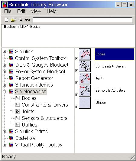
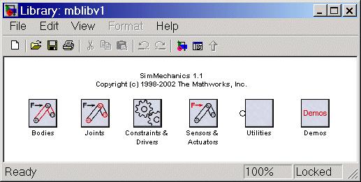
5 SimMechanics Introducing the SimMechanics Block Libraries: SimMechanics is organized into hierarchical libraries of closely related blocks: Bodies Library Joints Library Constraints & Drivers Library Sensors & Actuators Library Utilities Library Demos Library 5
6 6 SimMechanics
7 7 SimMechanics
8 SimMechanics Bodies Library The Bodies library provides the Body block for representing user-defined bodies by their mass properties (masses and inertia tensors), their positions and orientations, and their attached Body coordinate systems (CSs). This library also contains the Ground block representing immobile ground points, which have their own Grounded CSs. 8
9 SimMechanics Joints Library The Joints library provides the blocks to represent the relative motions between bodies as degrees of freedom (DoFs). The library is made up of assembled Joints listed individually and two sublibraries of specialized Joint blocks. An assembled joint restricts the Body CSs on the two bodies to which it is connected. The assembled Joints are the primitive Prismatic, Revolute, and Spherical blocks and ready-made composite Joints. Unless it is explicitly labeled as disassembled, you can assume a generic Joint block is assembled. 9
10 SimMechanics Constraints & Drivers Library The Constraints & Drivers library provides blocks to specify prior restrictions on DoFs between Bodies. These restrictions can be time-independent constraints or time-dependent driving of DoFs with Simulink signals. 10
11 SimMechanics Sensors & Actuators Library The Sensors & Actuators library provides blocks for sensing and initiating the motions of joints and bodies. These blocks play a special role in connecting SimMechanics blocks to other Simulink blocks. 11
12 SimMechanics Utilities Library The Utilities library contains miscellaneous blocks useful in building models. Demos Library The Demos library contains prewritten Simulink demonstration models using SimMechanics and other Simulink blocks, as well as Stateflow blocks. Double-clicking the Demos library icon calls the Help browser and displays the SimMechanics demos list. 12
13 Creating SimMechanics Models Creating SimMechanics Models: Essential Steps to Build a Model Essential Steps to Configure and Run a Model 13
14 Essential Steps to Build a Model: Select Ground, Body, and Joint blocks. Position and connect blocks. Configure Body blocks. Configure Joint blocks. Select, connect, and configure Constraint and Driver blocks. Select, connect, and configure Actuator and Sensor blocks. 14
15 Select Ground, Body, and Joint blocks. From the Bodies and Joints libraries, drag and drop the Body and Joint blocks needed to represent your machine, including at least one Ground block, into a Simulink model window. The Machine Environment block represents your machine's mechanical settings. Ground blocks represent immobile ground points at rest in absolute (inertial) space. Body blocks represent rigid bodies. Joint blocks represent relative motions between the Body blocks to which they are connected. 15
16 1-Body: Rigid body with frames, inertia and geometry The Body block represents a rigid body with properties you customize. The representation that you specify must include: The body's mass and moment of inertia tensor The coordinates for the body's center of gravity (CG) One or more Body coordinate systems (CSs) 16
17 17
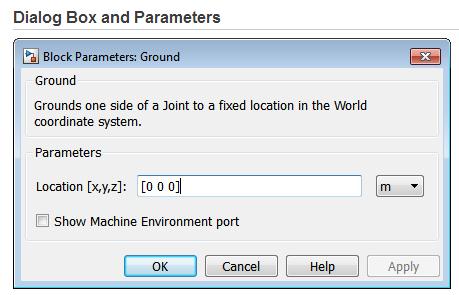
18 2- Ground: Fixed point attached to world Essential Steps to Build a Model Ground is a type of Body, but you can connect only one side of a Ground to a Joint block. A Ground block automatically carries a grounded coordinate system (CS). This Grounded CS is inertial, at rest in the World reference frame, with coordinate axes parallel to the World axes: +x points right +y points up (gravity in -y direction) +z points out of the screen, in three dimensions Enter the position of the ground point translated from the origin of the World CS. The position is specified as a translation vector (x,y,z), with components projected onto the fixed World CS axes. Set the Ground position units using the pull-down menu to the right. The defaults are [0 0 0] and m (meters). 18
19 19
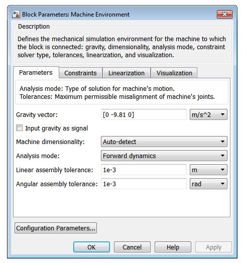
20 3- Machine Environment: block allows you to view and change the mechanical environment settings for one machine in your model This block determines the following settings for the machine: How to simulate the machine How to interpret mechanical constraints How to linearize the simulation Whether and how to display the machine in visualization 20
21 21
22 4- Assembled Joints: 22


23 The Revolute block: Revolute Motion of Follower (blue) Relative to Base (red) 23


24 The Prismatic block: Prismatic Motion of Follower (blue) Relative to Base (red) 24
25 5-Constraints and Drivers 25
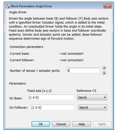
26 Angle Driver Essential Steps to Build a Model Driver specifying a time-dependent angle between two body axis vectors Current base When you connect the base (B) connector port on the Angle Driver block to a Body CS Port on a Body, this parameter is automatically reset to the name of this Body CS. Current follower When you connect the follower (F) connector port on the Angle Driver block to a Body CS Port on a Body, this parameter is automatically reset to the name of this Body CS. 26
27 27


28 Velocity Driver: Essential Steps to Build a Model Linear and angular velocity components of base and follower body coordinate systems The Velocity Driver block drives a linear combination of the projected translational and angular velocities of two Bodies. 28
29 6-Actuators and Sensors Initiate, impose, and measure mechanical motion

30 Body Actuator: Essential Steps to Build a Model Time-dependent force and torque used to actuate a body The Body Actuator block actuates a Body block with a generalized force signal, representing a force/torque applied to the body: Force for translational motion Torque for rotational motion
31 Joint Actuator: Essential Steps to Build a Model Time-dependent force, torque, or motion input to a joint A joint between two bodies represents relative degrees of freedom (DoFs) between the bodies. The Joint Actuator block actuates a Joint block connected between two Bodies with one of these signals: A generalized force: Force for translational motion along a prismatic joint primitive Torque for rotational motion about a revolute joint primitive A motion: Translational motion for a prismatic joint primitive, in terms of linear position, velocity, and acceleration. Rotational motion for a revolute joint primitive, in terms of angular position, velocity, and acceleration.
32
33 Joint Sensor: The Joint Sensor block measures the position, velocity, and/or acceleration of a joint primitive in a Joint block. It also measures the reaction force and torque across the Joint. The Joint Sensor measures the motion along/about the joint axis (or about the pivot point for a spherical primitive) in the reference coordinate system (CS) specified for that joint primitive in the Joint's dialog. The Joint connects a base and a follower Body at one body coordinate system on each body. The base-follower sequence determines the sense of the motion, which is defined as follower relative to base.
34
35 Position and connect blocks. Place Joint and Body blocks in proper relative position in the model window and connect them in the proper order. The essential result of this step is creation of a valid tree block diagram made of Ground Joint Body Joint Body... Body with an open or closed topology and where at least one of the bodies is a Ground block. A Body can have more than two Joints attached, marking a branching of the sequence. But Joints must be attached to two and only two Bodies. 35
36 Configuring the Position Fields The Position fields for each Body CS specify the position of that CS's origin as a translation vector: The numerical components of the vector carry units. The translation vector's components are oriented with respect to another set of CS axes. The origin is displaced from the origin of another, pre-existing CS in your machine by this translation vector. Highlight each Body CS to configure it. 36

37 Configuring the Position Fields 37
38 Configure Body blocks Click the Body blocks to open their dialog boxes; specify their mass properties (masses and moments of inertia), then position and orient the Bodies and Grounds relative to the World coordinate system (CS) or to other CSs. You set up Body CSs here. 38

39 Configure Joint blocks. Click each of the Joint blocks to open its dialog box and set translation and rotation axes and spherical pivot points. 39
40 Select, connect, and configure Constraint and Driver blocks. From the Constraints & Drivers library, drag, drop, and connect Constraint and Driver blocks in between pairs of Body blocks. Open and configure each Constraint/Driver s dialog box to restrict or drive the relative motion between the two respective bodies of each constrained/driven pair. Configure Joint blocks. Select, connect, and configure Actuator and Sensor blocks. From the Sensors & Actuators library, drag and drop the Actuator and Sensor blocks that you need to impart and sense motion. Reconfigure Body, Joint, and Constraint/Driver blocks to accept Sensor and Actuator connections. Connect Sensor and Actuator blocks. Specify control signals (applied forces/torques or motions) through Actuators and measure motions through Sensors. 40
41 Select, connect, and configure Constraint and Driver blocks. From the Constraints & Drivers library, drag, drop, and connect Constraint and Driver blocks in between pairs of Body blocks. Open and configure each Constraint/Driver s dialog box to restrict or drive the relative motion between the two respective bodies of each constrained/driven pair. Configure Joint blocks. Select, connect, and configure Actuator and Sensor blocks. From the Sensors & Actuators library, drag and drop the Actuator and Sensor blocks that you need to impart and sense motion. Reconfigure Body, Joint, and Constraint/Driver blocks to accept Sensor and Actuator connections. Connect Sensor and Actuator blocks. Specify control signals (applied forces/torques or motions) through Actuators and measure motions through Sensors. 41
42 Essential Steps to Configure and Run a Model Essential Steps to Configure and Run a Model: SimMechanics offers four analysis modes for running a machine model. The mode you will probably use most often, at least at first, is Forward Dynamics. But a more complete analysis of a machine makes use of the Kinematics, Inverse Dynamics, and Trimming modes as well. You can create multiple versions of the model, each with the same underlying machine, but connected to Sensors and Actuators and configured differently for different modes. 42
43 Essential Steps to Configure and Run a Model Essential Steps to Configure and Run a Model: You can also use the powerful visualization and animation features of SimMechanics. You can visualize your machine as you build it or after you are finished but before you start the simulation, as a tool for debugging the machine geometry. You can also animate the machine model as you simulate. Choose the analysis mode and configuring visualization, as well as other important settings, in the Mechanical Environment Settings dialog box. You might also need to reconfigure the Simulink Simulation Parameters dialog for SimMechanics models. 43
There is no need to submit any report and you just need to finish the three tutorials as well as the example.
 The first three tutorials are selected from the MATLAB/Simulink help. The fourth example is a simple SimMechanics example which can help you learn the SimMechanics more. You can find more detailed information
SimMechanics Getting Started Guide. R2013b
 SimMechanics Getting Started Guide R2013b How to Contact MathWorks www.mathworks.com Web comp.soft-sys.matlab Newsgroup www.mathworks.com/contact_ts.html Technical Support suggest@mathworks.com bugs@mathworks.com
2. Motion Analysis - Sim-Mechanics
 2 Motion Analysis - Sim-Mechanics Figure 1 - The RR manipulator frames The following table tabulates the summary of different types of analysis that is performed for the RR manipulator introduced in the
We are IntechOpen, the world s leading publisher of Open Access books Built by scientists, for scientists. International authors and editors
 We are IntechOpen, the world s leading publisher of Open Access books Built by scientists, for scientists 3,800 116,000 120M Open access books available International authors and editors Downloads Our
Rigid Dynamic Analysis in Workbench
 Rigid Dynamic Analysis in Workbench 1-1 Introduction Rigid Dynamic Analysis: Calculates dynamic response of an assembly of rigid bodies. Can be used to study the kinematics of an assembly. Bodies are linked
A simple example. Assume we want to find the change in the rotation angles to get the end effector to G. Effect of changing s
 CENG 732 Computer Animation This week Inverse Kinematics (continued) Rigid Body Simulation Bodies in free fall Bodies in contact Spring 2006-2007 Week 5 Inverse Kinematics Physically Based Rigid Body Simulation
MODELING AND DYNAMIC ANALYSIS OF 6-DOF PARALLEL MANIPULATOR
 MODELING AND DYNAMIC ANALYSIS OF 6-DOF PARALLEL MANIPULATOR N Narayan Rao 1, T Ashok 2, Anup Kumar Tammana 3 1 Assistant Professor, Department of Mechanical Engineering, VFSTRU, Guntur, India. nandurerao@gmail.com
Working Model Tutorial for Slider Crank
 Notes_02_01 1 of 15 1) Start Working Model 2D Working Model Tutorial for Slider Crank 2) Set display and units Select View then Workspace Check the X,Y Axes and Coordinates boxes and then select Close
Development of a Novel MultiBody Mechatronic Model for Five-Axis CNC Machine Tool
 Development of a Novel MultiBody Mechatronic Model for Five-Axis CNC Machine Tool M. Papananias, S. Sztendel, C. Pislaru EPSRC Centre for Innovative Manufacturing in Advanced Metrology, University of Huddersfield,
Rotational3D Efficient modelling of 3D effects in rotational mechanics
 Rotational3D - Efficient Modelling of 3D Effects in Rotational Mechanics Rotational3D Efficient modelling of 3D effects in rotational mechanics Johan Andreasson Magnus Gäfvert Modelon AB Ideon Science
Mathematical Modelling Using SimScape (Mechanical Systems)
") Experiment Three Mathematical Modelling Using SimScape (Mechanical Systems) Control Systems Laboratory Dr. Zaer Abo Hammour Dr. Zaer Abo Hammour Control Systems Laboratory 1. Translational Mechanical System
Experiment Three Mathematical Modelling Using SimScape (Mechanical Systems) Control Systems Laboratory Dr. Zaer Abo Hammour Dr. Zaer Abo Hammour Control Systems Laboratory 1. Translational Mechanical System
ROBOTICS 01PEEQW. Basilio Bona DAUIN Politecnico di Torino
 ROBOTICS 01PEEQW Basilio Bona DAUIN Politecnico di Torino Kinematic chains Readings & prerequisites From the MSMS course one shall already be familiar with Reference systems and transformations Vectors
Robotics kinematics and Dynamics
 Robotics kinematics and Dynamics C. Sivakumar Assistant Professor Department of Mechanical Engineering BSA Crescent Institute of Science and Technology 1 Robot kinematics KINEMATICS the analytical study
Lesson 1: Introduction to Pro/MECHANICA Motion
 Lesson 1: Introduction to Pro/MECHANICA Motion 1.1 Overview of the Lesson The purpose of this lesson is to provide you with a brief overview of Pro/MECHANICA Motion, also called Motion in this book. Motion
Mechanical System and SimMechanics Simulation
 American Journal of Mechanical Engineering, 3, Vol., No. 7, 555 Available online at http://pubs.sciepub.com/ajme//7/ Science and Education Publishing DOI:.69/ajme--7 Mechanical System and SimMechanics
ME Week 11 Create Joints Project
 One of the most important elements of dynamic simulation is setting up and verifying that proper joints are created. Joints are links between two rigid components that applies force from the first component
Model Library Mechanics
 Model Library Mechanics Using the libraries Mechanics 1D (Linear), Mechanics 1D (Rotary), Modal System incl. ANSYS interface, and MBS Mechanics (3D) incl. CAD import via STL and the additional options
Lecture «Robot Dynamics»: Multi-body Kinematics
 Lecture «Robot Dynamics»: Multi-body Kinematics 151-0851-00 V lecture: CAB G11 Tuesday 10:15 12:00, every week exercise: HG E1.2 Wednesday 8:15 10:00, according to schedule (about every 2nd week) Marco
Lecture «Robot Dynamics»: Kinematics 3
 Lecture «Robot Dynamics»: Kinematics 3 151-0851-00 V lecture: CAB G11 Tuesday 10:15 12:00, every week exercise: HG E1.2 Wednesday 8:15 10:00, according to schedule (about every 2nd week) Marco Hutter,
Modeling of Humanoid Systems Using Deductive Approach
 INFOTEH-JAHORINA Vol. 12, March 2013. Modeling of Humanoid Systems Using Deductive Approach Miloš D Jovanović Robotics laboratory Mihailo Pupin Institute Belgrade, Serbia milos.jovanovic@pupin.rs Veljko
Basilio Bona ROBOTICA 03CFIOR 1
 Kinematic chains 1 Readings & prerequisites Chapter 2 (prerequisites) Reference systems Vectors Matrices Rotations, translations, roto-translations Homogeneous representation of vectors and matrices Chapter
Robot mechanics and kinematics
 University of Pisa Master of Science in Computer Science Course of Robotics (ROB) A.Y. 2016/17 cecilia.laschi@santannapisa.it http://didawiki.cli.di.unipi.it/doku.php/magistraleinformatica/rob/start Robot
Lecture «Robot Dynamics»: Kinematics 3
 Lecture «Robot Dynamics»: Kinematics 3 151-0851-00 V lecture: CAB G11 Tuesday 10:15 12:00, every week exercise: HG E1.2 Wednesday 8:15 10:00, according to schedule (about every 2nd week) office hour: LEE
11. Kinematic models of contact Mechanics of Manipulation
 11. Kinematic models of contact Mechanics of Manipulation Matt Mason matt.mason@cs.cmu.edu http://www.cs.cmu.edu/~mason Carnegie Mellon Lecture 11. Mechanics of Manipulation p.1 Lecture 11. Kinematic models
Dynamic Analysis of Manipulator Arm for 6-legged Robot
 American Journal of Mechanical Engineering, 2013, Vol. 1, No. 7, 365-369 Available online at http://pubs.sciepub.com/ajme/1/7/42 Science and Education Publishing DOI:10.12691/ajme-1-7-42 Dynamic Analysis
Kinematics: Intro. Kinematics is study of motion
 Kinematics is study of motion Kinematics: Intro Concerned with mechanisms and how they transfer and transform motion Mechanisms can be machines, skeletons, etc. Important for CG since need to animate complex
Robotics. SAAST Robotics Robot Arms
 SAAST Robotics 008 Robot Arms Vijay Kumar Professor of Mechanical Engineering and Applied Mechanics and Professor of Computer and Information Science University of Pennsylvania Topics Types of robot arms
Dynamic Simulation of a KUKA KR5 Industrial Robot using MATLAB SimMechanics
 Dynamic Simulation of a KUKA KR5 Industrial Robot using MATLAB SimMechanics Arun Dayal Udai, C.G Rajeevlochana, Subir Kumar Saha Abstract The paper discusses a method for the dynamic simulation of a KUKA
INSTITUTE OF AERONAUTICAL ENGINEERING
 Name Code Class Branch Page 1 INSTITUTE OF AERONAUTICAL ENGINEERING : ROBOTICS (Autonomous) Dundigal, Hyderabad - 500 0 MECHANICAL ENGINEERING TUTORIAL QUESTION BANK : A7055 : IV B. Tech I Semester : MECHANICAL
ROBOTICS 01PEEQW. Basilio Bona DAUIN Politecnico di Torino
 ROBOTICS 01PEEQW Basilio Bona DAUIN Politecnico di Torino Control Part 4 Other control strategies These slides are devoted to two advanced control approaches, namely Operational space control Interaction
Robot mechanics and kinematics
 University of Pisa Master of Science in Computer Science Course of Robotics (ROB) A.Y. 2017/18 cecilia.laschi@santannapisa.it http://didawiki.cli.di.unipi.it/doku.php/magistraleinformatica/rob/start Robot
Reconfigurable Manipulator Simulation for Robotics and Multimodal Machine Learning Application: Aaria
 Reconfigurable Manipulator Simulation for Robotics and Multimodal Machine Learning Application: Aaria Arttu Hautakoski, Mohammad M. Aref, and Jouni Mattila Laboratory of Automation and Hydraulic Engineering
Chapter 5 Modeling and Simulation of Mechanism
 Chapter 5 Modeling and Simulation of Mechanism In the present study, KED analysis of four bar planar mechanism using MATLAB program and ANSYS software has been carried out. The analysis has also been carried
EEE 187: Robotics Summary 2
 1 EEE 187: Robotics Summary 2 09/05/2017 Robotic system components A robotic system has three major components: Actuators: the muscles of the robot Sensors: provide information about the environment and
Chapter 4. Mechanism Design and Analysis
 Chapter 4. Mechanism Design and Analysis All mechanical devices containing moving parts are composed of some type of mechanism. A mechanism is a group of links interacting with each other through joints
1. Introduction 1 2. Mathematical Representation of Robots
 1. Introduction 1 1.1 Introduction 1 1.2 Brief History 1 1.3 Types of Robots 7 1.4 Technology of Robots 9 1.5 Basic Principles in Robotics 12 1.6 Notation 15 1.7 Symbolic Computation and Numerical Analysis
Lab 12: Joint Driver and Force Creation Lab
 Page 1 Lab 12: Joint Driver and Force Creation Lab Objective This lab will continue to introduce the definition of Joint Drivers. These drivers will prescribe the motion in the three translational degrees
Chapter 1 Introduction
 Chapter 1 Introduction Generally all considerations in the force analysis of mechanisms, whether static or dynamic, the links are assumed to be rigid. The complexity of the mathematical analysis of mechanisms
Theory of Machines Course # 1
 Theory of Machines Course # 1 Ayman Nada Assistant Professor Jazan University, KSA. arobust@tedata.net.eg March 29, 2010 ii Sucess is not coming in a day 1 2 Chapter 1 INTRODUCTION 1.1 Introduction Mechanisms
Animation. Keyframe animation. CS4620/5620: Lecture 30. Rigid motion: the simplest deformation. Controlling shape for animation
 Keyframe animation CS4620/5620: Lecture 30 Animation Keyframing is the technique used for pose-to-pose animation User creates key poses just enough to indicate what the motion is supposed to be Interpolate
Flexible Modeling and Simulation Architecture for Haptic Control of Maritime Cranes and Robotic Arms
 Flexible Modeling and Simulation Architecture for Haptic Control of Maritime Cranes and Robotic Arms F. Sanfilippo, H. P. Hildre, V. Æsøy and H.X. Zhang Department of Maritime Technology and Operation
Kinematics. Kinematics analyzes the geometry of a manipulator, robot or machine motion. The essential concept is a position.
 Kinematics Kinematics analyzes the geometry of a manipulator, robot or machine motion. The essential concept is a position. 1/31 Statics deals with the forces and moments which are aplied on the mechanism
COPYRIGHTED MATERIAL INTRODUCTION CHAPTER 1
 CHAPTER 1 INTRODUCTION Modern mechanical and aerospace systems are often very complex and consist of many components interconnected by joints and force elements such as springs, dampers, and actuators.
Modelling of mechanical system CREATING OF KINEMATIC CHAINS
 Modelling of mechanical system CREATING OF KINEMATIC CHAINS Mechanism Definitions 1. a system or structure of moving parts that performs some function 2. is each system reciprocally joined moveable bodies
Attach to this tutorial, there are some drawings to create the CAD models with Solid Works.
 Modeling and Simulation Tutorial 1. (Slider Mechanism) Objective: To Create Slider Mechanism Elements to Use: SolidWorks Cosmos Motion Dynamics Books Description: This tutorial explains how to set up different
Teaching the Design of Parallel Manipulators and Their Controllers Implementing MATLAB, Simulink, SimMechanics and CAD*
 Int. J. Engng Ed. Vol. 21, No. 5, pp. 838±845, 2005 0949-149X/91 $3.00+0.00 Printed in Great Britain. # 2005 TEMPUS Publications. Teaching the Design of Parallel Manipulators and Their Controllers Implementing
INTRODUCTION CHAPTER 1
 CHAPTER 1 INTRODUCTION Modern mechanical and aerospace systems are often very complex and consist of many components interconnected by joints and force elements such as springs, dampers, and actuators.
SIMULATION ENVIRONMENT PROPOSAL, ANALYSIS AND CONTROL OF A STEWART PLATFORM MANIPULATOR
 SIMULATION ENVIRONMENT PROPOSAL, ANALYSIS AND CONTROL OF A STEWART PLATFORM MANIPULATOR Fabian Andres Lara Molina, Joao Mauricio Rosario, Oscar Fernando Aviles Sanchez UNICAMP (DPM-FEM), Campinas-SP, Brazil,
10/25/2018. Robotics and automation. Dr. Ibrahim Al-Naimi. Chapter two. Introduction To Robot Manipulators
 Robotics and automation Dr. Ibrahim Al-Naimi Chapter two Introduction To Robot Manipulators 1 Robotic Industrial Manipulators A robot manipulator is an electronically controlled mechanism, consisting of
Quick Start Training Guide
 Quick Start Training Guide Table of Contents 1 INTRODUCTION TO MAPLESIM... 5 1.1 USER INTERFACE... 5 2 WORKING WITH A SAMPLE MODEL... 7 2.1 RUNNING A SIMULATION... 7 2.2 GRAPHICAL OUTPUT... 7 2.3 3D VISUALIZATION...
Introduction to Solid Modeling Using SolidWorks 2008 COSMOSMotion Tutorial Page 1
 Introduction to Solid Modeling Using SolidWorks 2008 COSMOSMotion Tutorial Page 1 In this tutorial, we will learn the basics of performing motion analysis using COSMOSMotion. Although the tutorial can
Mobile Robots Locomotion
 Mobile Robots Locomotion Institute for Software Technology 1 Course Outline 1. Introduction to Mobile Robots 2. Locomotion 3. Sensors 4. Localization 5. Environment Modelling 6. Reactive Navigation 2 Today
MTRX4700 Experimental Robotics
 MTRX 4700 : Experimental Robotics Lecture 2 Stefan B. Williams Slide 1 Course Outline Week Date Content Labs Due Dates 1 5 Mar Introduction, history & philosophy of robotics 2 12 Mar Robot kinematics &
Applications. Human and animal motion Robotics control Hair Plants Molecular motion
 Multibody dynamics Applications Human and animal motion Robotics control Hair Plants Molecular motion Generalized coordinates Virtual work and generalized forces Lagrangian dynamics for mass points
Parallel Robots. Mechanics and Control H AMID D. TAG HI RAD. CRC Press. Taylor & Francis Group. Taylor & Francis Croup, Boca Raton London NewYoric
 Parallel Robots Mechanics and Control H AMID D TAG HI RAD CRC Press Taylor & Francis Group Boca Raton London NewYoric CRC Press Is an Imprint of the Taylor & Francis Croup, an informs business Contents
Lecture VI: Constraints and Controllers. Parts Based on Erin Catto s Box2D Tutorial
 Lecture VI: Constraints and Controllers Parts Based on Erin Catto s Box2D Tutorial Motion Constraints In practice, no rigid body is free to move around on its own. Movement is constrained: wheels on a
The Mathematical Model and Computer Simulation of a Quadruped Robot
 Research Experience for Undergraduates 2014 Milwaukee School of Engineering National Science Foundation Grant June 1- August 8, 2014 The Mathematical Model and Computer Simulation of a Quadruped Robot
Kinematics - Introduction. Robotics. Kinematics - Introduction. Vladimír Smutný
 Kinematics - Introduction Robotics Kinematics - Introduction Vladimír Smutný Center for Machine Perception Czech Institute for Informatics, Robotics, and Cybernetics (CIIRC) Czech Technical University
ME 3222 Design & Manufacturing II. Creating and Animating a Slider-Crank in Creo Elements (Version 2.0)
") ME 3222 Design & Manufacturing II Creating and Animating a Slider-Crank in Creo Elements (Version 2.0) Tom Chase February 18, 2016 Overview This document explains how to create a mechanism and animate
ME 3222 Design & Manufacturing II Creating and Animating a Slider-Crank in Creo Elements (Version 2.0) Tom Chase February 18, 2016 Overview This document explains how to create a mechanism and animate
Inherently Balanced Double Bennett Linkage
 Inherently Balanced Double Bennett Linkage V. van der Wijk Delft University of Technology - Dep. of Precision and Microsystems Engineering Mechatronic System Design, e-mail: v.vanderwijk@tudelft.nl Abstract.
Simulation and Modeling of 6-DOF Robot Manipulator Using Matlab Software
 Simulation and Modeling of 6-DOF Robot Manipulator Using Matlab Software 1 Thavamani.P, 2 Ramesh.K, 3 Sundari.B 1 M.E Scholar, Applied Electronics, JCET, Dharmapuri, Tamilnadu, India 2 Associate Professor,
Theory and Design Issues of Underwater Manipulator
 Theory and Design Issues of Underwater Manipulator Irfan Abd Rahman, Surina Mat Suboh, Mohd Rizal Arshad Univesiti Sains Malaysia albiruni81@gmail.com, sue_keegurlz@yahoo.com, rizal@eng.usm.my Abstract
Dynamics Analysis for a 3-PRS Spatial Parallel Manipulator-Wearable Haptic Thimble
 Dynamics Analysis for a 3-PRS Spatial Parallel Manipulator-Wearable Haptic Thimble Masoud Moeini, University of Hamburg, Oct 216 [Wearable Haptic Thimble,A Developing Guide and Tutorial,Francesco Chinello]
Table of Contents. Chapter 1. Modeling and Identification of Serial Robots... 1 Wisama KHALIL and Etienne DOMBRE
 Chapter 1. Modeling and Identification of Serial Robots.... 1 Wisama KHALIL and Etienne DOMBRE 1.1. Introduction... 1 1.2. Geometric modeling... 2 1.2.1. Geometric description... 2 1.2.2. Direct geometric
An Improved Dynamic Modeling of a 3-RPS Parallel Manipulator using the concept of DeNOC Matrices
 An Improved Dynamic Modeling of a 3-RPS Parallel Manipulator using the concept of DeNOC Matrices A. Rahmani Hanzaki, E. Yoosefi Abstract A recursive dynamic modeling of a three-dof parallel robot, namely,
An Introduction to Motion Analysis Applications with SolidWorks Motion, Instructor Guide
 Engineering Design and Technology Series An Introduction to Motion Analysis Applications with SolidWorks Motion, Instructor Guide Dassault Systèmes SolidWorks Corporation 300 Baker Avenue Concord, Massachusetts
A Co-simulation Approach Based on ADAMS-MATLAB for Development of an Industrial Manipulator
 ISSN 2395-1621 A Co-simulation Approach Based on ADAMS-MATLAB for Development of an Industrial Manipulator #1 SwapnilDokhe, #2 ShaileshPimpale, 1 swapnildokhe@gmail.com 2 shailesh_pimpale@rediffmail.com
MathWorks Technology Session at GE Physical System Modeling with Simulink / Simscape
 SimPowerSystems SimMechanics SimHydraulics SimDriveline SimElectronics MathWorks Technology Session at GE Physical System Modeling with Simulink / Simscape Simscape MATLAB, Simulink September 13, 2012
Using Siemens NX 11 Software. Assembly example - Gears
 Using Siemens NX 11 Software Assembly example - Gears Based on a NX tutorial from the NX documentation 1. 1 Introduction. Start NX 11 and create a new assembly file called assembly_gear.prt. 2 Adding a
Using RecurDyn. Contents
 Using RecurDyn Contents 1.0 Multibody Dynamics Overview... 2 2.0 Multibody Dynamics Applications... 3 3.0 What is RecurDyn and how is it different?... 4 4.0 Types of RecurDyn Analysis... 5 5.0 MBD Simulation
MCE/EEC 647/747: Robot Dynamics and Control. Lecture 3: Forward and Inverse Kinematics
 MCE/EEC 647/747: Robot Dynamics and Control Lecture 3: Forward and Inverse Kinematics Denavit-Hartenberg Convention Reading: SHV Chapter 3 Mechanical Engineering Hanz Richter, PhD MCE503 p.1/12 Aims of
Analytical and Applied Kinematics
 Analytical and Applied Kinematics Vito Moreno moreno@engr.uconn.edu 860-614-2365 (cell) http://www.engr.uconn.edu/~moreno Office EB1, hours Thursdays 10:00 to 5:00 1 This course introduces a unified and
MACHINES AND MECHANISMS
 MACHINES AND MECHANISMS APPLIED KINEMATIC ANALYSIS Fourth Edition David H. Myszka University of Dayton PEARSON ж rentice Hall Pearson Education International Boston Columbus Indianapolis New York San Francisco
ÉCOLE POLYTECHNIQUE DE MONTRÉAL
 ÉCOLE POLYTECHNIQUE DE MONTRÉAL MODELIZATION OF A 3-PSP 3-DOF PARALLEL MANIPULATOR USED AS FLIGHT SIMULATOR MOVING SEAT. MASTER IN ENGINEERING PROJET III MEC693 SUBMITTED TO: Luc Baron Ph.D. Mechanical
Analysis of a 4 Bar Crank-Rocker Mechanism Using COSMOSMotion
 Analysis of a 4 Bar Crank-Rocker Mechanism Using COSMOSMotion ME345: Modeling and Simulation Professor Frank Fisher Stevens Institute of Technology Last updated: June 29th, 2009 Table of Contents 1. Introduction
PPGEE Robot Dynamics I
 PPGEE Electrical Engineering Graduate Program UFMG April 2014 1 Introduction to Robotics 2 3 4 5 What is a Robot? According to RIA Robot Institute of America A Robot is a reprogrammable multifunctional
3. Manipulator Kinematics. Division of Electronic Engineering Prof. Jaebyung Park
 3. Manipulator Kinematics Division of Electronic Engineering Prof. Jaebyung Park Introduction Kinematics Kinematics is the science of motion which treats motion without regard to the forces that cause
Animations in Creo 3.0
 Animations in Creo 3.0 ME170 Part I. Introduction & Outline Animations provide useful demonstrations and analyses of a mechanism's motion. This document will present two ways to create a motion animation
Kinematic Synthesis. October 6, 2015 Mark Plecnik
 Kinematic Synthesis October 6, 2015 Mark Plecnik Classifying Mechanisms Several dichotomies Serial and Parallel Few DOFS and Many DOFS Planar/Spherical and Spatial Rigid and Compliant Mechanism Trade-offs
UNIVERSITY OF OSLO. Faculty of Mathematics and Natural Sciences
 Page 1 UNIVERSITY OF OSLO Faculty of Mathematics and Natural Sciences Exam in INF3480 Introduction to Robotics Day of exam: May 31 st 2010 Exam hours: 3 hours This examination paper consists of 5 page(s).
Development of a Ground Based Cooperating Spacecraft Testbed for Research and Education
 DIPARTIMENTO DI INGEGNERIA INDUSTRIALE Development of a Ground Based Cooperating Spacecraft Testbed for Research and Education Mattia Mazzucato, Sergio Tronco, Andrea Valmorbida, Fabio Scibona and Enrico
John Hsu Nate Koenig ROSCon 2012
 John Hsu Nate Koenig ROSCon 2012 Outline What is Gazebo, and why should you use it Overview and architecture Environment modeling Robot modeling Interfaces Getting Help Simulation for Robots Towards accurate
Generative Part Structural Analysis Expert
 CATIA V5 Training Foils Generative Part Structural Analysis Expert Version 5 Release 19 September 2008 EDU_CAT_EN_GPE_FI_V5R19 About this course Objectives of the course Upon completion of this course
Engine with Propeller Tutorial (Professional)
") Engine with Propeller Tutorial (Professional) Copyright 2017 FunctionBay, Inc. All rights reserved. User and training documentation from FunctionBay, Inc. is subjected to the copyright laws of the Republic
Engine with Propeller Tutorial (Professional) Copyright 2017 FunctionBay, Inc. All rights reserved. User and training documentation from FunctionBay, Inc. is subjected to the copyright laws of the Republic
AC : AN ALTERNATIVE APPROACH FOR TEACHING MULTIBODY DYNAMICS
 AC 2009-575: AN ALTERNATIVE APPROACH FOR TEACHING MULTIBODY DYNAMICS George Sutherland, Rochester Institute of Technology DR. GEORGE H. SUTHERLAND is a professor in the Manufacturing & Mechanical Engineering
Automatic Control Industrial robotics
 Automatic Control Industrial robotics Prof. Luca Bascetta (luca.bascetta@polimi.it) Politecnico di Milano Dipartimento di Elettronica, Informazione e Bioingegneria Prof. Luca Bascetta Industrial robots
PRACTICAL SESSION 4: FORWARD DYNAMICS. Arturo Gil Aparicio.
 PRACTICAL SESSION 4: FORWARD DYNAMICS Arturo Gil Aparicio arturo.gil@umh.es OBJECTIVES After this practical session, the student should be able to: Simulate the movement of a simple mechanism using the
Shape Optimization of a Curved Beam Hopping Robot
 Prof. Dr. Fumiya Iida Master-Thesis Shape Optimization of a Curved Beam Hopping Robot Autumn Term 2012 Supervised by: Nandan Maheshwari Xiaoxiang Yu Murat Reis Author: Dominik Naef Acknowledgments I would
MDP646: ROBOTICS ENGINEERING. Mechanical Design & Production Department Faculty of Engineering Cairo University Egypt. Prof. Said M.
 MDP646: ROBOTICS ENGINEERING Mechanical Design & Production Department Faculty of Engineering Cairo University Egypt Prof. Said M. Megahed APPENDIX A: PROBLEM SETS AND PROJECTS Problem Set # Due 3 rd week
Written exams of Robotics 1
 Written exams of Robotics 1 http://www.diag.uniroma1.it/~deluca/rob1_en.php All materials are in English, unless indicated (oldies are in Year Date (mm.dd) Number of exercises Topics 2018 06.11 2 Planar
DYNAMICS OF SPACE ROBOTIC ARM DURING INTERACTIONS WITH NON COOPERATIVE OBJECTS
 DYNAMICS OF SPACE ROBOTIC ARM DURING INTERACTIONS WITH NON COOPERATIVE OBJECTS Karol Seweryn 1, Marek Banaszkiewicz 1, Bernd Maediger 2, Tomasz Rybus 1, Josef Sommer 2 1 Space Research Centre of the Polish
Simulation-Based Design of Robotic Systems
 Simulation-Based Design of Robotic Systems Shadi Mohammad Munshi* & Erik Van Voorthuysen School of Mechanical and Manufacturing Engineering, The University of New South Wales, Sydney, NSW 2052 shadimunshi@hotmail.com,
Human Motion. Session Speaker Dr. M. D. Deshpande. AML2506 Biomechanics and Flow Simulation PEMP-AML2506
 AML2506 Biomechanics and Flow Simulation Day 02A Kinematic Concepts for Analyzing Human Motion Session Speaker Dr. M. D. Deshpande 1 Session Objectives At the end of this session the delegate would have
Proceedings of the 2013 SpaceVision Conference November 7-10 th, Tempe, AZ, USA ABSTRACT
 Proceedings of the 2013 SpaceVision Conference November 7-10 th, Tempe, AZ, USA Development of arm controller for robotic satellite servicing demonstrations Kristina Monakhova University at Buffalo, the
Structural Configurations of Manipulators
 Structural Configurations of Manipulators 1 In this homework, I have given information about the basic structural configurations of the manipulators with the concerned illustrations. 1) The Manipulator
A MECHATRONIC APPROACH OF THE WINDSHIELD WIPER MECHANISMS
 A MECHATRONIC APPROACH OF THE WINDSHIELD WIPER MECHANISMS Alexandru Cătălin Transilvania University of Braşov calex@unitbv.ro Keywords: windshield wiper mechanism, dynamic simulation, control system, virtual
This week. CENG 732 Computer Animation. Warping an Object. Warping an Object. 2D Grid Deformation. Warping an Object.
 CENG 732 Computer Animation Spring 2006-2007 Week 4 Shape Deformation Animating Articulated Structures: Forward Kinematics/Inverse Kinematics This week Shape Deformation FFD: Free Form Deformation Hierarchical
SimWise. 3D Dynamic Motion, and Stress Analysis. integrated with Alibre Design
 SimWise 3D Dynamic Motion, and Stress Analysis integrated with Alibre Design SimWise 4D for Alibre Integrated Motion Simulation and Stress Analysis SimWise 4D is a software tool that allows the functional
Inverse Kinematics. Given a desired position (p) & orientation (R) of the end-effector
 & orientation (R) of the end-effector") Inverse Kinematics Given a desired position (p) & orientation (R) of the end-effector q ( q, q, q ) 1 2 n Find the joint variables which can bring the robot the desired configuration z y x 1 The Inverse
Inverse Kinematics Given a desired position (p) & orientation (R) of the end-effector q ( q, q, q ) 1 2 n Find the joint variables which can bring the robot the desired configuration z y x 1 The Inverse
SAMPLE STUDY MATERIAL. Mechanical Engineering. Postal Correspondence Course. Theory of Machines. GATE, IES & PSUs
 TOM - ME GATE, IES, PSU 1 SAMPLE STUDY MATERIAL Mechanical Engineering ME Postal Correspondence Course Theory of Machines GATE, IES & PSUs TOM - ME GATE, IES, PSU 2 C O N T E N T TOPIC 1. MACHANISMS AND