3D Software Interpretation of Reas s Processes
|
|
|
- Philomena Cook
- 6 years ago
- Views:
Transcription
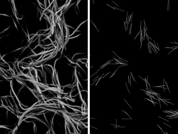
1 3D Software Interpretation of Reas s Processes Tomasz Sebastian Rybiarczyk University of Illinois at Chicago Dept. of Computer Science Chicago, IL, United States trybia2@uic.edu ABSTRACT The emergence has long been a fascinating process exploited in arts and sciences. Casey Edwin Barker Reas heavily builds upon this phenomenon in his creations, where the compositions of various forms and behaviors give rise to images of highly distinct and mesmerizing shapes. This work describes an attempt to extend his work to the third dimension. Presented are the design decisions and trade-offs that had to be taken to best approximate the original work in 3D. The implementation of the work is also detailed to provide insights into presenting the process of emergence in interactive framerates. Selected original works are compared against the results as a mean of evaluation. ACM Classification Keywords I.3.3. Computer Graphics: Picture/Image Generation Author Keywords Computer Graphics; Design; Performance INTRODUCTION The notion of emergence has a long history. It was as early as the 19th century when John Stewart Mill claimed that a combined effect of several causes cannot be reduced to its component causes [3]. Steven Johnson in his book, "Emergence", gives the defines the emergence as follows: In the simple terms (emergent systems) solve problems by drawing on masses of relatively stupid elements, rather than a single, intelligent "executive branch". They are bottom-up systems, not top-down [3]. Many people, inspired by the idea of emergence began producing work of art incorporating it. The phenomena found its outlets also in computer-generated art. Casey Reas is another artist who grasped the concepts of emergence, defined a number of processes and developed software to produce 2D images which are "software interpretation of Process descriptions" [6]. Permission to make digital or hard copies of all or part of this work for personal or classroom use is granted without fee provided that copies are not made or distributed for profit or commercial advantage and that copies bear this notice and the full citation on the first page. Despite the fascinating effects that come to life from various software interpretations authored by Reas, there was no attempt to interpret his descriptions in a three dimensional universe. This paper documents the first such attempt. Early experiments were meant to approximate the original work as close as possible. Additional goal was to allow the viewers to observe the emergence process from any perspective in interactive framerates. This early work produced quite promising results. The paper provides brief introduction to th original work of Casey Reas. Next, it documents the issues we considered when extending the original work to 3D. The implementation considerations in sufficient detail are also provided. Lastly, we present our results and compare them to images of Reas s original work (Figure 2). ORIGINAL WORK Casey Reas s vast portfolio contains many distinct compositions. Each one of them represents software visualization of various phenomena and draws inspiration from many sources. In this paper we focus on the series of Processes, composed of many Elements, which in turn encompass Forms and Behaviors. The definitions are provided in the following subsections. Process Definitions Reas describes the Element as a machine composed of a Form and one or more Behaviors. The most common Forms in his work are circles and lines. Behaviors determine how the Element reacts certain events such as collisions (and overlap) with other Elements, collisions with universe boundaries, advancement paths. The Process is an environment for Elements and describes how to visualize the interactions between the Elements and other events involving the Elements in a universe. The description of each Process is given in English and its interpretation is left for the programmer. Examples For completeness, several Processes are described below. These descriptions are taken directly from Reas s Process Compendium text [6]. Their original software interpretations are illustrated in Figure 1. Process 4 - A rectangular surface filled with varying sizes of Element 1. Draw a line from the centers of Elements that are touching. Set the value of the shortest possible

2 (a) Process 4 (b) Process 10 (c) Process 18 Figure 1: Original software interpretation of selected Processes line to black and the longest to white, with varying grays representing values in between. Process 10 - Position a circle at the center of a rectangular surface. Set the center of the circle as the origin for a large group of Element 1. When an Element moves beyond the edge of its circle, return to the origin. Draw a line from the centers of Elements that are touching. Set the value of the shortest possible line to black and the longest to white, with varying grays representing values in between. Process 18 - A rectangular surface filled with instances of Element 5, each with a different size and gray value. Draw a quadrilateral connecting the endpoints of each pair of Elements that are touching. Increase the opacity of the quadrilateral while the Elements are touching and decrease while they are not. CROSSING THE DIMENSION BOUNDARY As noted by Reas, it is up to an individual how one interprets the Process description. It becomes apparent that extending the ideas to the third dimension, there are even more occasions to employ personal judgment on design. This section explains some of the notable difficulties that had to be addressed in the process. Representation in 3D Due to the fact that the work is the first attempt in 3D interpretation of Reas work, it was of great importance to retain the same interface for producing the images. As the original work involves drawing lines for the most part, the same primitive is used in this work. As seen in the previous section, some Elements consist of circles and the other consist of lines. In this approach, for obvious reasons, the use of circles was substituted with spheres. The use of lines remained in place for other Forms. Interpretation of Process Text for 3D An additional design decision that had to be taken was the interpretation of some of the Behaviors. For instance, Behavior 3 changes a direction of the Element. It is not obvious how the direction should be modified in this case. In the original work, as shown in the Compendium Lecture video [5], rotates the Elements clockwise at the same constant rate. In 3D however, this kind of behavior would not result in a desired effect. Our approach generates normal vector for each pair of colliding Elements. Cross product of the normal and the direction vectors is computed to produce the tangent. This vector then serves as an axis around which the direction vector is rotated. The angular velocity is kept constant for all Elements in a Process but it is assigned different value on per process basis. Behavior 4 moves the Element away from an Element it overlaps. While this description seems straight forward, in practice it is not known at what rate should the Elements be pulled away from each other and how does this rate correspond Elements velocity. It is also important to maintain the overlap state for a certain duration in order to produce meaningful results in context of visual representation. In our approach, each Element maintains a list of elements it collides with in current discrete step. The list capacity is limited to a certain number (currently 4) so that some amount of overlap conditions occur. The mean of the directions from current Element to colliding Elements is computed and used to translate current Element with speed proportional to the magnitude of its velocity. This interpretation was found to provide a nice balance between the number of overlap conditions and the efficiency constraints presented in the following subsection. Outside the Behavior description realm there is also one other way that influences the emergence significantly: some Processes move the Elements to the center, once they collide the bounding surface. This is where our implementation violates the description in order to throttle the amount of lines drawn. Instead, the spawning position for Elements are moved further away from the origin with each generation step. The rate at which this happens is an arbitrary value that yields the best visual result. Differences The fact that the original work produces images on a two dimensional surface signifies that the results of each generation steps are accumulated in the framebuffer according to the blending equation being used. The technique revolves around keeping the framebuffer contents from frame to frame. As a consequence of this, the drawing routines are relatively
3 inexpensive operations since they must render only the results of the latest generation step. Our technique, however, must maintain all the geometry produced in the past steps to allow viewing from different perspectives. This implies drawing increasingly large number of simple primitives. In order to handle the task efficiently, it is necessary to allocated large buffers on the gpu and update them with latest results. Section 4 covers this approach in a greater detail. The immediate steps that can be taken to combat efficiency issues are to throttle the amount of lines being generated at each step. Through experiment and observation, several factors that directly influence the number of lines being produced were identified. These factor include but are not limited to the number of Elements, the size of the bounding volume, the velocity of Elements and the initial positions of the Elements. Several of these issues have been addressed by the means of assigning different fine-tuned parameters for different types of Processes. Assigning arbitrary values to these parameters can have a negative impact on the quality of the visualization. The following subsection details a way to counter some of the negative impact. Transparency The great part of the aesthetic quality of the original work can be attributed to how the results of each generation step are combined with contents already present in the framebuffer. In this case, the results are simply drawn on top with varying opacity levels. Since the generation takes place on a two dimensional surface, there is no notion of depth in such context. In 3D, however, in order to best approximated the transparency effect, it is necessary to take into account the order in which the Elements are drawn. It is apparent that due to the overwhelming amount of lines being drawn at any time, all the traditional methods of organizing geometry in a 3D scene become ineffective due to the large overhead of rebuilding the space partitioning tree structures. As noted previously, one of the goals is to allow observing the emergence process from any perspective in interactive frame rates. Several alternative approaches in the domain of Order Independent Transparency (OIT) were considered. The A-Buffer approach by Carpenter [2] or any approach that maintains fragment lists is impractical due to high depth complexity of the scene we are trying to render. Similar issue affects depth peeling since it generally requires a large number of rendering passes, proportional to depth complexity [1]. McGuire and Bavoil describe an approach that require only two passes but the expectation is that the data we to be blended already exists in offscreen buffers [4]. We finally settled for an easy and straight forward approach of using a commutative blending equation, described by Sellers [7]. With simply adding the source and destination colors, we were able to achieve arguably convincing transparency effect. For effectiveness, it is necessary to choose colors with low per-channel intensity as to not cause the color clipping. We found it benefiting to express color in HSL. This way the lightness component corresponds to the opacity value in traditional blending. Also, adjusting lightness to an appropriately high value can greatly reduce the amount of lines that need to be blended together. This consequently allowed to reduce the number of Elements and increase performance. Additional design choice was to express varying gray levels (as required by most of the Process descriptions) with varying hue component. IMPLEMENTATION Our work was implemented using OpenGL graphics API. For efficiency purposes it heavily relies on hardware instancing an thus requires ARB_draw_instanced and ARB_instanced_arrays to be available. Any implementation and supporting version 3.3 Core of the the API satisfies this requirement. Depending on the Process, different sizes of perinstance attribute buffers are allocated. The sizes vary from 50 thousand to 5 million. Some implementations such as Intel Mesa may not support this many instances per call. Collision detection is deferred to Bullet Physics. Depending on the type of the Form the Elements use, either sphere or cylinder collision shapes are employed. CONCLUSIONS In this work we have attempted to extend the original work of Casey Reas to the third dimension. Several Processes have been selected and implemented to approximate the original effect. Numerous design choices and reinterpretations had to be taken to achieve the desired effect. Our ultimate goal was to view the emergence process from any perspective and observe the growth in realtime. For comparison, our work was set aside the 2D Process visualization images. While some of our implementations exhibit greater differences to Reas work, we are fairly confident that additional fine-tuning of input parameters will yield much better results. Some differences are also due to the way the transparency is handled in our implementation. Employing a better blending model for our purposes will allow viewers to see much more detail that makes the original work aesthetically appealing. In spite of the number of issues we faced, we believe our work has a quality on its own. It opens the gates to many more possibilities. If all the issues we are currently experiencing are resolved, there exist bright perspectives to transform our implementation into a toolkit for visualizing emergence processes in 3D. REFERENCES 1. Louis Bavoil and Kevin Myers Order independent transparency with dual depth peeling. Technical Report. Nvidia. Retrieved December 2, 2015 from src/dual_depth_peeling/doc/dualdepthpeeling.pdf. 2. Loren Carpenter The A-buffer, an Antialiased Hidden Surface Method. In Proceedings of the 11th annual conference on Computer graphics and interactive techniques (SIGGRAPH 84). ACM, Dan Collins Breeding the Evolutionary: Interactive Emergence in Art and Education. In 4th Annual Digital Arts Symposium: Neural Network. cfa/art/people/faculty/collins/emergence/emergence.htm


")


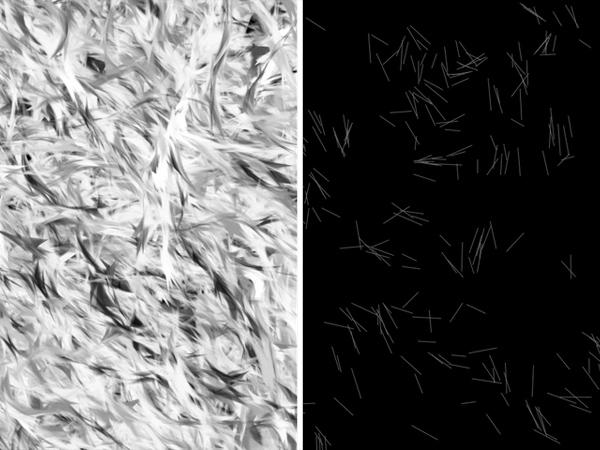

4 (a) Process 4 (b) Process 6 (c) Process 10 (d) Process 12 (e) Process 17 (f) Process 18 Figure 2: Comparison of the original (top images) and our (bottom images) software interpretations
5 4. Morgan McGuire and Louis Bavoil Weighted Blended Order-Independent Transparency. Journal of Computer Graphics Techniques (JCGT) 2, 2 (18 December 2013), Case Reas. Compendium Lecture. Video. (????). Retrieved September 22, 2015 from 6. Casey Reas Process Compendium REAS Studio. 7. Graham Sellers Order Independent Transparency. (20 August 2013). Retrieved Decemeber 2, 2015 from is-order-independent-transparency-really-necessary/.
Order Independent Transparency with Dual Depth Peeling. Louis Bavoil, Kevin Myers
 Order Independent Transparency with Dual Depth Peeling Louis Bavoil, Kevin Myers Document Change History Version Date Responsible Reason for Change 1.0 February 9 2008 Louis Bavoil Initial release Abstract
Constant-Memory Order-Independent Transparency Techniques
 Constant-Memory Order-Independent Transparency Techniques Louis Bavoil lbavoil@nvidia.com Eric Enderton eenderton@nvidia.com Document Change History Version Date Responsible Reason for Change 1 March 14,
Multimedia Technology CHAPTER 4. Video and Animation
 CHAPTER 4 Video and Animation - Both video and animation give us a sense of motion. They exploit some properties of human eye s ability of viewing pictures. - Motion video is the element of multimedia
PowerVR Hardware. Architecture Overview for Developers
 Public Imagination Technologies PowerVR Hardware Public. This publication contains proprietary information which is subject to change without notice and is supplied 'as is' without warranty of any kind.
BCC Comet Generator Source XY Source Z Destination XY Destination Z Completion Time
 BCC Comet Generator Comet creates an auto-animated comet that streaks across the screen. The comet is compromised of particles whose sizes, shapes, and colors can be adjusted. You can also set the length
CS451Real-time Rendering Pipeline
 1 CS451Real-time Rendering Pipeline JYH-MING LIEN DEPARTMENT OF COMPUTER SCIENCE GEORGE MASON UNIVERSITY Based on Tomas Akenine-Möller s lecture note You say that you render a 3D 2 scene, but what does
8/5/2012. Introduction. Transparency. Anti-Aliasing. Applications. Conclusions. Introduction
 Introduction Transparency effects and applications Anti-Aliasing impact in the final image Why combine Transparency with Anti-Aliasing? Marilena Maule João Comba Rafael Torchelsen Rui Bastos UFRGS UFRGS
Applications of Explicit Early-Z Culling
 Applications of Explicit Early-Z Culling Jason L. Mitchell ATI Research Pedro V. Sander ATI Research Introduction In past years, in the SIGGRAPH Real-Time Shading course, we have covered the details of
Previously... contour or image rendering in 2D
 Volume Rendering Visualisation Lecture 10 Taku Komura Institute for Perception, Action & Behaviour School of Informatics Volume Rendering 1 Previously... contour or image rendering in 2D 2D Contour line
Physically-Based Laser Simulation
 Physically-Based Laser Simulation Greg Reshko Carnegie Mellon University reshko@cs.cmu.edu Dave Mowatt Carnegie Mellon University dmowatt@andrew.cmu.edu Abstract In this paper, we describe our work on
Ray tracing based fast refraction method for an object seen through a cylindrical glass
 20th International Congress on Modelling and Simulation, Adelaide, Australia, 1 6 December 2013 www.mssanz.org.au/modsim2013 Ray tracing based fast refraction method for an object seen through a cylindrical
DEFERRED RENDERING STEFAN MÜLLER ARISONA, ETH ZURICH SMA/
 DEFERRED RENDERING STEFAN MÜLLER ARISONA, ETH ZURICH SMA/2013-11-04 DEFERRED RENDERING? CONTENTS 1. The traditional approach: Forward rendering 2. Deferred rendering (DR) overview 3. Example uses of DR:
An Efficient Approach for Emphasizing Regions of Interest in Ray-Casting based Volume Rendering
 An Efficient Approach for Emphasizing Regions of Interest in Ray-Casting based Volume Rendering T. Ropinski, F. Steinicke, K. Hinrichs Institut für Informatik, Westfälische Wilhelms-Universität Münster
Here s the general problem we want to solve efficiently: Given a light and a set of pixels in view space, resolve occlusion between each pixel and
 1 Here s the general problem we want to solve efficiently: Given a light and a set of pixels in view space, resolve occlusion between each pixel and the light. 2 To visualize this problem, consider the
4.5 VISIBLE SURFACE DETECTION METHODES
 4.5 VISIBLE SURFACE DETECTION METHODES A major consideration in the generation of realistic graphics displays is identifying those parts of a scene that are visible from a chosen viewing position. There
Rasterization Overview
 Rendering Overview The process of generating an image given a virtual camera objects light sources Various techniques rasterization (topic of this course) raytracing (topic of the course Advanced Computer
Computer Graphics CS 543 Lecture 1 (Part I) Prof Emmanuel Agu. Computer Science Dept. Worcester Polytechnic Institute (WPI)
 Prof Emmanuel Agu. Computer Science Dept. Worcester Polytechnic Institute (WPI)") Computer Graphics CS 543 Lecture 1 (Part I) Prof Emmanuel Agu Computer Science Dept. Worcester Polytechnic Institute (WPI) About This Course Computer graphics: algorithms, mathematics, data structures..
Computer Graphics CS 543 Lecture 1 (Part I) Prof Emmanuel Agu Computer Science Dept. Worcester Polytechnic Institute (WPI) About This Course Computer graphics: algorithms, mathematics, data structures..
Graphics and Interaction Rendering pipeline & object modelling
 433-324 Graphics and Interaction Rendering pipeline & object modelling Department of Computer Science and Software Engineering The Lecture outline Introduction to Modelling Polygonal geometry The rendering
CSE 167: Introduction to Computer Graphics Lecture #18: More Effects. Jürgen P. Schulze, Ph.D. University of California, San Diego Fall Quarter 2016
 CSE 167: Introduction to Computer Graphics Lecture #18: More Effects Jürgen P. Schulze, Ph.D. University of California, San Diego Fall Quarter 2016 Announcements TA evaluations CAPE Final project blog
Persistent Background Effects for Realtime Applications Greg Lane, April 2009
 Persistent Background Effects for Realtime Applications Greg Lane, April 2009 0. Abstract This paper outlines the general use of the GPU interface defined in shader languages, for the design of large-scale
Multi-View Soft Shadows. Louis Bavoil
 Multi-View Soft Shadows Louis Bavoil lbavoil@nvidia.com Document Change History Version Date Responsible Reason for Change 1.0 March 16, 2011 Louis Bavoil Initial release Overview The Multi-View Soft Shadows
The Rasterization Pipeline
 Lecture 5: The Rasterization Pipeline (and its implementation on GPUs) Computer Graphics CMU 15-462/15-662, Fall 2015 What you know how to do (at this point in the course) y y z x (w, h) z x Position objects
Volume Rendering. Computer Animation and Visualisation Lecture 9. Taku Komura. Institute for Perception, Action & Behaviour School of Informatics
 Volume Rendering Computer Animation and Visualisation Lecture 9 Taku Komura Institute for Perception, Action & Behaviour School of Informatics Volume Rendering 1 Volume Data Usually, a data uniformly distributed
1. Mesh Coloring a.) Assign unique color to each polygon based on the polygon id.
 Assign unique color to each polygon based on the polygon id.") 1. Mesh Coloring a.) Assign unique color to each polygon based on the polygon id. Figure 1: The dragon model is shown rendered using a coloring scheme based on coloring each triangle face according to
1. Mesh Coloring a.) Assign unique color to each polygon based on the polygon id. Figure 1: The dragon model is shown rendered using a coloring scheme based on coloring each triangle face according to
CS 381 Computer Graphics, Fall 2012 Midterm Exam Solutions. The Midterm Exam was given in class on Tuesday, October 16, 2012.
 CS 381 Computer Graphics, Fall 2012 Midterm Exam Solutions The Midterm Exam was given in class on Tuesday, October 16, 2012. 1. [7 pts] Synthetic-Camera Model. Describe the Synthetic-Camera Model : how
UNIVERSITY OF NEBRASKA AT OMAHA Computer Science 4620/8626 Computer Graphics Spring 2014 Homework Set 1 Suggested Answers
 UNIVERSITY OF NEBRASKA AT OMAHA Computer Science 4620/8626 Computer Graphics Spring 2014 Homework Set 1 Suggested Answers 1. How long would it take to load an 800 by 600 frame buffer with 16 bits per pixel
COMPUTER GRAPHICS COURSE. Rendering Pipelines
 COMPUTER GRAPHICS COURSE Rendering Pipelines Georgios Papaioannou - 2014 A Rendering Pipeline Rendering or Graphics Pipeline is the sequence of steps that we use to create the final image Many graphics/rendering
Chapter 10 Computation Culling with Explicit Early-Z and Dynamic Flow Control
 Chapter 10 Computation Culling with Explicit Early-Z and Dynamic Flow Control Pedro V. Sander ATI Research John R. Isidoro ATI Research Jason L. Mitchell ATI Research Introduction In last year s course,
SimTenero Particle Physics
 SimTenero Particle Physics Getting Started The heart of the particle system is the Emitter. This represents the point in space where particles will be created and contains all of the parameters that define
2.11 Particle Systems
 2.11 Particle Systems 320491: Advanced Graphics - Chapter 2 152 Particle Systems Lagrangian method not mesh-based set of particles to model time-dependent phenomena such as snow fire smoke 320491: Advanced
Illustrating Number Sequences
 Illustrating Number Sequences L. Kerry Mitchell 3783 West Park Avenue Chandler, AZ 85226 USA lkmitch@att.net Abstract While critically important mathematically, number sequences can also be foundational
Screen Space Ambient Occlusion TSBK03: Advanced Game Programming
 Screen Space Ambient Occlusion TSBK03: Advanced Game Programming August Nam-Ki Ek, Oscar Johnson and Ramin Assadi March 5, 2015 This project report discusses our approach of implementing Screen Space Ambient
Ray Tracing through Viewing Portals
 Ray Tracing through Viewing Portals Introduction Chris Young Igor Stolarsky April 23, 2008 This paper presents a method for ray tracing scenes containing viewing portals circular planes that act as windows
Spring 2009 Prof. Hyesoon Kim
 Spring 2009 Prof. Hyesoon Kim Application Geometry Rasterizer CPU Each stage cane be also pipelined The slowest of the pipeline stage determines the rendering speed. Frames per second (fps) Executes on
Chapter 3. Texture mapping. Learning Goals: Assignment Lab 3: Implement a single program, which fulfills the requirements:
 Chapter 3 Texture mapping Learning Goals: 1. To understand texture mapping mechanisms in VRT 2. To import external textures and to create new textures 3. To manipulate and interact with textures 4. To
ENHANCING THE CONTROL AND PERFORMANCE OF PARTICLE SYSTEMS THROUGH THE USE OF LOCAL ENVIRONMENTS. Abstract
 ENHANCING THE CONTROL AND PERFORMANCE OF PARTICLE SYSTEMS THROUGH THE USE OF LOCAL ENVIRONMENTS Daniel O. Kutz Richard R. Eckert State University of New York at Binghamton Binghamton, NY 13902 Abstract
COMP30019 Graphics and Interaction Scan Converting Polygons and Lines
 COMP30019 Graphics and Interaction Scan Converting Polygons and Lines Department of Computer Science and Software Engineering The Lecture outline Introduction Scan conversion Scan-line algorithm Edge coherence
CS559: Computer Graphics. Lecture 12: Antialiasing & Visibility Li Zhang Spring 2008
 CS559: Computer Graphics Lecture 12: Antialiasing & Visibility Li Zhang Spring 2008 Antialising Today Hidden Surface Removal Reading: Shirley ch 3.7 8 OpenGL ch 1 Last time A 2 (x 0 y 0 ) (x 1 y 1 ) P
Synthesis of Textures with Intricate Geometries using BTF and Large Number of Textured Micropolygons. Abstract. 2. Related studies. 1.
 Synthesis of Textures with Intricate Geometries using BTF and Large Number of Textured Micropolygons sub047 Abstract BTF has been studied extensively and much progress has been done for measurements, compression
Spring 2011 Prof. Hyesoon Kim
 Spring 2011 Prof. Hyesoon Kim Application Geometry Rasterizer CPU Each stage cane be also pipelined The slowest of the pipeline stage determines the rendering speed. Frames per second (fps) Executes on
CS 4620 Program 3: Pipeline
 CS 4620 Program 3: Pipeline out: Wednesday 14 October 2009 due: Friday 30 October 2009 1 Introduction In this assignment, you will implement several types of shading in a simple software graphics pipeline.
Midterm Exam Fundamentals of Computer Graphics (COMP 557) Thurs. Feb. 19, 2015 Professor Michael Langer
 Thurs. Feb. 19, 2015 Professor Michael Langer") Midterm Exam Fundamentals of Computer Graphics (COMP 557) Thurs. Feb. 19, 2015 Professor Michael Langer The exam consists of 10 questions. There are 2 points per question for a total of 20 points. You
Midterm Exam Fundamentals of Computer Graphics (COMP 557) Thurs. Feb. 19, 2015 Professor Michael Langer The exam consists of 10 questions. There are 2 points per question for a total of 20 points. You
Chapter 8 Virtual Memory
 Operating Systems: Internals and Design Principles Chapter 8 Virtual Memory Seventh Edition William Stallings Operating Systems: Internals and Design Principles You re gonna need a bigger boat. Steven
In this chapter, we will investigate what have become the standard applications of the integral:
 Chapter 8 Overview: Applications of Integrals Calculus, like most mathematical fields, began with trying to solve everyday problems. The theory and operations were formalized later. As early as 70 BC,
Buffers, Textures, Compositing, and Blending. Overview. Buffers. David Carr Virtual Environments, Fundamentals Spring 2005 Based on Slides by E.
 INSTITUTIONEN FÖR SYSTEMTEKNIK LULEÅ TEKNISKA UNIVERSITET Buffers, Textures, Compositing, and Blending David Carr Virtual Environments, Fundamentals Spring 2005 Based on Slides by E. Angel Compositing,
Adaptive Point Cloud Rendering
 1 Adaptive Point Cloud Rendering Project Plan Final Group: May13-11 Christopher Jeffers Eric Jensen Joel Rausch Client: Siemens PLM Software Client Contact: Michael Carter Adviser: Simanta Mitra 4/29/13
Computer Graphics. Shadows
 Computer Graphics Lecture 10 Shadows Taku Komura Today Shadows Overview Projective shadows Shadow texture Shadow volume Shadow map Soft shadows Why Shadows? Shadows tell us about the relative locations
Volume Shadows Tutorial Nuclear / the Lab
 Volume Shadows Tutorial Nuclear / the Lab Introduction As you probably know the most popular rendering technique, when speed is more important than quality (i.e. realtime rendering), is polygon rasterization.
Hidden surface removal. Computer Graphics
 Lecture Hidden Surface Removal and Rasterization Taku Komura Hidden surface removal Drawing polygonal faces on screen consumes CPU cycles Illumination We cannot see every surface in scene We don t want
COMPUTER DESIGN OF REPEATING HYPERBOLIC PATTERNS
 COMPUTER DESIGN OF REPEATING HYPERBOLIC PATTERNS Douglas Dunham University of Minnesota Duluth Department of Computer Science 1114 Kirby Drive Duluth, Minnesota 55812-2496 USA ddunham@d.umn.edu Abstract:
Rendering Grass Terrains in Real-Time with Dynamic Lighting. Kévin Boulanger, Sumanta Pattanaik, Kadi Bouatouch August 1st 2006
 Rendering Grass Terrains in Real-Time with Dynamic Lighting Kévin Boulanger, Sumanta Pattanaik, Kadi Bouatouch August 1st 2006 Goal Rendering millions of grass blades, at any distance, in real-time, with:
GUERRILLA DEVELOP CONFERENCE JULY 07 BRIGHTON
 Deferred Rendering in Killzone 2 Michal Valient Senior Programmer, Guerrilla Talk Outline Forward & Deferred Rendering Overview G-Buffer Layout Shader Creation Deferred Rendering in Detail Rendering Passes
Display Technologies: CRTs Raster Displays
 Rasterization Display Technologies: CRTs Raster Displays Raster: A rectangular array of points or dots Pixel: One dot or picture element of the raster Scanline: A row of pixels Rasterize: find the set
Scan line algorithm. Jacobs University Visualization and Computer Graphics Lab : Graphics and Visualization 272
 Scan line algorithm The scan line algorithm is an alternative to the seed fill algorithm. It does not require scan conversion of the edges before filling the polygons It can be applied simultaneously to
Web Annotator. Dale Reed, Sam John Computer Science Department University of Illinois at Chicago Chicago, IL
 Web Annotator Dale Reed, Sam John Computer Science Department University of Illinois at Chicago Chicago, IL 60607-7053 reed@uic.edu, sjohn@cs.uic.edu Abstract The World Wide Web is increasingly becoming
A Shadow Volume Algorithm for Opaque and Transparent Non-Manifold Casters
 jgt 2008/7/20 22:19 page 1 #1 Vol. [VOL], No. [ISS]: 1?? A Shadow Volume Algorithm for Opaque and Transparent Non-Manifold Casters Byungmoon Kim 1, Kihwan Kim 2, Greg Turk 2 1 NVIDIA, 2 Georgia Institute
Scanline Rendering 2 1/42
 Scanline Rendering 2 1/42 Review 1. Set up a Camera the viewing frustum has near and far clipping planes 2. Create some Geometry made out of triangles 3. Place the geometry in the scene using Transforms
Introduction to Visualization and Computer Graphics
 Introduction to Visualization and Computer Graphics DH2320, Fall 2015 Prof. Dr. Tino Weinkauf Introduction to Visualization and Computer Graphics Visibility Shading 3D Rendering Geometric Model Color Perspective
Robotics Project. Final Report. Computer Science University of Minnesota. December 17, 2007
 Robotics Project Final Report Computer Science 5551 University of Minnesota December 17, 2007 Peter Bailey, Matt Beckler, Thomas Bishop, and John Saxton Abstract: A solution of the parallel-parking problem
CS130 : Computer Graphics Lecture 2: Graphics Pipeline. Tamar Shinar Computer Science & Engineering UC Riverside
 CS130 : Computer Graphics Lecture 2: Graphics Pipeline Tamar Shinar Computer Science & Engineering UC Riverside Raster Devices and Images Raster Devices - raster displays show images as a rectangular array
Evolutionary form design: the application of genetic algorithmic techniques to computer-aided product design
 Loughborough University Institutional Repository Evolutionary form design: the application of genetic algorithmic techniques to computer-aided product design This item was submitted to Loughborough University's
Abstract. Introduction. Kevin Todisco
 - Kevin Todisco Figure 1: A large scale example of the simulation. The leftmost image shows the beginning of the test case, and shows how the fluid refracts the environment around it. The middle image
Space Filling: A new algorithm for procedural creation of game assets
 Space Filling: A new algorithm for procedural creation of game assets Paul Bourke ivec@uwa, The University of Western Australia, 35 Stirling Hwy, Crawley, Perth, West Australia 6009. Email: paul.bourke@uwa.edu.au
Deferred Rendering Due: Wednesday November 15 at 10pm
 CMSC 23700 Autumn 2017 Introduction to Computer Graphics Project 4 November 2, 2017 Deferred Rendering Due: Wednesday November 15 at 10pm 1 Summary This assignment uses the same application architecture
Pipeline Operations. CS 4620 Lecture Steve Marschner. Cornell CS4620 Spring 2018 Lecture 11
 Pipeline Operations CS 4620 Lecture 11 1 Pipeline you are here APPLICATION COMMAND STREAM 3D transformations; shading VERTEX PROCESSING TRANSFORMED GEOMETRY conversion of primitives to pixels RASTERIZATION
graphics pipeline computer graphics graphics pipeline 2009 fabio pellacini 1
 graphics pipeline computer graphics graphics pipeline 2009 fabio pellacini 1 graphics pipeline sequence of operations to generate an image using object-order processing primitives processed one-at-a-time
Parallelizing Graphics Pipeline Execution (+ Basics of Characterizing a Rendering Workload)
") Lecture 2: Parallelizing Graphics Pipeline Execution (+ Basics of Characterizing a Rendering Workload) Visual Computing Systems Today Finishing up from last time Brief discussion of graphics workload metrics
Lecture 2: Parallelizing Graphics Pipeline Execution (+ Basics of Characterizing a Rendering Workload) Visual Computing Systems Today Finishing up from last time Brief discussion of graphics workload metrics
Computer Graphics Prof. Sukhendu Das Dept. of Computer Science and Engineering Indian Institute of Technology, Madras Lecture - 24 Solid Modelling
 Computer Graphics Prof. Sukhendu Das Dept. of Computer Science and Engineering Indian Institute of Technology, Madras Lecture - 24 Solid Modelling Welcome to the lectures on computer graphics. We have
CS4620/5620: Lecture 14 Pipeline
 CS4620/5620: Lecture 14 Pipeline 1 Rasterizing triangles Summary 1! evaluation of linear functions on pixel grid 2! functions defined by parameter values at vertices 3! using extra parameters to determine
Tiled Textures What if Miro Had Painted a Sphere
 Tiled Textures What if Miro Had Painted a Sphere ERGUN AKLEMAN, AVNEET KAUR and LORI GREEN Visualization Sciences Program, Department of Architecture Texas A&M University December 26, 2005 Abstract We
graphics pipeline computer graphics graphics pipeline 2009 fabio pellacini 1
 graphics pipeline computer graphics graphics pipeline 2009 fabio pellacini 1 graphics pipeline sequence of operations to generate an image using object-order processing primitives processed one-at-a-time
Notes on Photoshop s Defect in Simulation of Global Motion-Blurring
 Notes on Photoshop s Defect in Simulation of Global Motion-Blurring Li-Dong Cai Department of Computer Science, Jinan University Guangzhou 510632, CHINA ldcai@21cn.com ABSTRACT In restoration of global
Advanced Real- Time Cel Shading Techniques in OpenGL Adam Hutchins Sean Kim
 Advanced Real- Time Cel Shading Techniques in OpenGL Adam Hutchins Sean Kim Cel shading, also known as toon shading, is a non- photorealistic rending technique that has been used in many animations and
CHAPTER 1 Graphics Systems and Models 3
 ?????? 1 CHAPTER 1 Graphics Systems and Models 3 1.1 Applications of Computer Graphics 4 1.1.1 Display of Information............. 4 1.1.2 Design.................... 5 1.1.3 Simulation and Animation...........
Discrete Techniques. 11 th Week, Define a buffer by its spatial resolution (n m) and its depth (or precision) k, the number of
 and its depth (or precision) k, the number of") Discrete Techniques 11 th Week, 2010 Buffer Define a buffer by its spatial resolution (n m) and its depth (or precision) k, the number of bits/pixel Pixel OpenGL Frame Buffer OpenGL Buffers Color buffers
Discrete Techniques 11 th Week, 2010 Buffer Define a buffer by its spatial resolution (n m) and its depth (or precision) k, the number of bits/pixel Pixel OpenGL Frame Buffer OpenGL Buffers Color buffers
3D graphics, raster and colors CS312 Fall 2010
 Computer Graphics 3D graphics, raster and colors CS312 Fall 2010 Shift in CG Application Markets 1989-2000 2000 1989 3D Graphics Object description 3D graphics model Visualization 2D projection that simulates
Lesson 1: Introduction to Pro/MECHANICA Motion
 Lesson 1: Introduction to Pro/MECHANICA Motion 1.1 Overview of the Lesson The purpose of this lesson is to provide you with a brief overview of Pro/MECHANICA Motion, also called Motion in this book. Motion
Output models Drawing Rasterization Color models
 Output models Drawing Rasterization olor models Fall 2004 6.831 UI Design and Implementation 1 Fall 2004 6.831 UI Design and Implementation 2 omponents Graphical objects arranged in a tree with automatic
Pipeline Operations. CS 4620 Lecture 14
 Pipeline Operations CS 4620 Lecture 14 2014 Steve Marschner 1 Pipeline you are here APPLICATION COMMAND STREAM 3D transformations; shading VERTEX PROCESSING TRANSFORMED GEOMETRY conversion of primitives
Lecture 3 Sections 2.2, 4.4. Mon, Aug 31, 2009
 Model s Lecture 3 Sections 2.2, 4.4 World s Eye s Clip s s s Window s Hampden-Sydney College Mon, Aug 31, 2009 Outline Model s World s Eye s Clip s s s Window s 1 2 3 Model s World s Eye s Clip s s s Window
Artistic Rendering of Function-based Shape Models
 Artistic Rendering of Function-based Shape Models by Shunsuke Suzuki Faculty of Computer and Information Science Hosei University n00k1021@k.hosei.ac.jp Supervisor: Alexander Pasko March 2004 1 Abstract
TEAM 12: TERMANATOR PROJECT PROPOSAL. TEAM MEMBERS: Donald Eng Rodrigo Ipince Kevin Luu
 TEAM 12: TERMANATOR PROJECT PROPOSAL TEAM MEMBERS: Donald Eng Rodrigo Ipince Kevin Luu 1. INTRODUCTION: This project involves the design and implementation of a unique, first-person shooting game. The
Higher National Unit Specification. General information for centres. Unit title: CAD: 3D Modelling. Unit code: DW13 34
 Higher National Unit Specification General information for centres Unit code: DW13 34 Unit purpose: This Unit is designed to introduce candidates to computerised 3D modelling and enable them to understand
A Disk Head Scheduling Simulator
 A Disk Head Scheduling Simulator Steven Robbins Department of Computer Science University of Texas at San Antonio srobbins@cs.utsa.edu Abstract Disk head scheduling is a standard topic in undergraduate
CSE 167: Introduction to Computer Graphics Lecture #19: Wrapping Up. Jürgen P. Schulze, Ph.D. University of California, San Diego Fall Quarter 2017
 CSE 167: Introduction to Computer Graphics Lecture #19: Wrapping Up Jürgen P. Schulze, Ph.D. University of California, San Diego Fall Quarter 2017 Announcements TA evaluations CAPE Final project blog entries
The Traditional Graphics Pipeline
 Last Time? The Traditional Graphics Pipeline Participating Media Measuring BRDFs 3D Digitizing & Scattering BSSRDFs Monte Carlo Simulation Dipole Approximation Today Ray Casting / Tracing Advantages? Ray
Folding and Spiralling: The Word View
 Folding and Spiralling: The Word View Marcus Schaefer 1 CTI, DePaul University Chicago, Illinois 60604 Eric Sedgwick 2 CTI, DePaul University Chicago, Illinois 60604 Daniel Štefankovič 3 Computer Science
9. Visible-Surface Detection Methods
 9. Visible-Surface Detection Methods More information about Modelling and Perspective Viewing: Before going to visible surface detection, we first review and discuss the followings: 1. Modelling Transformation:
Shadows in the graphics pipeline
 Shadows in the graphics pipeline Steve Marschner Cornell University CS 569 Spring 2008, 19 February There are a number of visual cues that help let the viewer know about the 3D relationships between objects
A Hillclimbing Approach to Image Mosaics
 A Hillclimbing Approach to Image Mosaics Chris Allen Faculty Sponsor: Kenny Hunt, Department of Computer Science ABSTRACT This paper presents a hillclimbing approach to image mosaic creation. Our approach
Types of Edges. Why Edge Detection? Types of Edges. Edge Detection. Gradient. Edge Detection
 Why Edge Detection? How can an algorithm extract relevant information from an image that is enables the algorithm to recognize objects? The most important information for the interpretation of an image
Fast continuous collision detection among deformable Models using graphics processors CS-525 Presentation Presented by Harish
 Fast continuous collision detection among deformable Models using graphics processors CS-525 Presentation Presented by Harish Abstract: We present an interactive algorithm to perform continuous collision
Topic #1: Rasterization (Scan Conversion)
") Topic #1: Rasterization (Scan Conversion) We will generally model objects with geometric primitives points, lines, and polygons For display, we need to convert them to pixels for points it s obvious but
Topic #1: Rasterization (Scan Conversion) We will generally model objects with geometric primitives points, lines, and polygons For display, we need to convert them to pixels for points it s obvious but
Particle systems, collision detection, and ray tracing. Computer Graphics CSE 167 Lecture 17
 Particle systems, collision detection, and ray tracing Computer Graphics CSE 167 Lecture 17 CSE 167: Computer graphics Particle systems Collision detection Ray tracing CSE 167, Winter 2018 2 Particle systems
An Educational Rigid-Body Dynamics Physics Engine TJHSST Senior Research Project Proposal Computer Systems Lab
 An Educational Rigid-Body Dynamics Physics Engine TJHSST Senior Research Project Proposal Computer Systems Lab 2009-2010 Neal Milstein April 9, 2010 Abstract The goal of this project is to create a rigid-body
EE 4702 GPU Programming
 fr 1 Final Exam Review When / Where EE 4702 GPU Programming fr 1 Tuesday, 4 December 2018, 12:30-14:30 (12:30 PM - 2:30 PM) CST Room 226 Tureaud Hall (Here) Conditions Closed Book, Closed Notes Bring one
Selective Space Structures Manual
 Selective Space Structures Manual February 2017 CONTENTS 1 Contents 1 Overview and Concept 4 1.1 General Concept........................... 4 1.2 Modules................................ 6 2 The 3S Generator
Computer Graphics (CS 563) Lecture 4: Advanced Computer Graphics Image Based Effects: Part 2. Prof Emmanuel Agu
 Lecture 4: Advanced Computer Graphics Image Based Effects: Part 2. Prof Emmanuel Agu") Computer Graphics (CS 563) Lecture 4: Advanced Computer Graphics Image Based Effects: Part 2 Prof Emmanuel Agu Computer Science Dept. Worcester Polytechnic Institute (WPI) Image Processing Graphics concerned
Computer Graphics (CS 563) Lecture 4: Advanced Computer Graphics Image Based Effects: Part 2 Prof Emmanuel Agu Computer Science Dept. Worcester Polytechnic Institute (WPI) Image Processing Graphics concerned
Next-Generation Graphics on Larrabee. Tim Foley Intel Corp
 Next-Generation Graphics on Larrabee Tim Foley Intel Corp Motivation The killer app for GPGPU is graphics We ve seen Abstract models for parallel programming How those models map efficiently to Larrabee
(a) rotating 45 0 about the origin and then translating in the direction of vector I by 4 units and (b) translating and then rotation.
 rotating 45 0 about the origin and then translating in the direction of vector I by 4 units and (b) translating and then rotation.") Code No: R05221201 Set No. 1 1. (a) List and explain the applications of Computer Graphics. (b) With a neat cross- sectional view explain the functioning of CRT devices. 2. (a) Write the modified version
Code No: R05221201 Set No. 1 1. (a) List and explain the applications of Computer Graphics. (b) With a neat cross- sectional view explain the functioning of CRT devices. 2. (a) Write the modified version