Let s start with occluding contours (or interior and exterior silhouettes), and look at image-space algorithms. A very simple technique is to render
|
|
|
- Alvin Page
- 5 years ago
- Views:
Transcription
1 1
, then extract lines by doing some sort of image processing on the framebuffer (for simple")
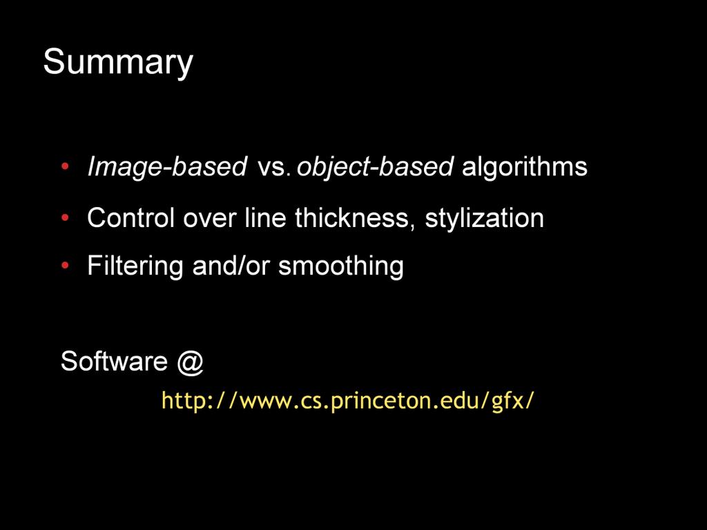
2 There are two major classes of algorithms for extracting most kinds of lines from 3D meshes. First, there are image-space algorithms that render something (such as a depth map or cosine-shaded model), then extract lines by doing some sort of image processing on the framebuffer (for simple operations such as thresholding, there are often ways of achieving the same effect using texture mapping, or vertex or pixel shaders). The advantage of this kind of algorithm is that it can be fast, easy to implement, and provides some notion of view-dependent level of detail. A major disadvantage is that it makes it difficult to control the appearance and stylization of the resulting lines. A second class of algorithm operates in object space on the model directly. These algorithms tend to be a little more complex, and it is more difficult to adapt them to take advantage of graphics hardware. On the other hand, they provide good control over stylization. Finally, there are hybrid (usually multi-pass) algorithms, which perform a bit of processing in object space, but the lines ultimately show up only in the frame buffer. These are much less general than the other kinds of algorithms, and are specialized for e.g. contours. 2
, then perform a thresholding step: any region darker than a threshold is set to black (or the line color), and anything")
3 Let s start with occluding contours (or interior and exterior silhouettes), and look at image-space algorithms. A very simple technique is to render a lit version of the model (without color), then perform a thresholding step: any region darker than a threshold is set to black (or the line color), and anything above the threshold is set to the background color. There are many ways to do this thresholding step as part of the rendering, using pixel shaders, texture mapping, environment mapping, etc. 3

4 One major problem with this algorithm is that the thickness of the lines can vary, sometimes quite a bit. There are a few tricks to get around this problem. 4
5 First, you can use a texture map indexed by n dot v, but use mipmapping. The trick is to make the width of the black region in the texture map the same width in all mipmap levels. 5
6 Another solution is to take advantage of the fact that, for a constant-curvature region, you can determine how thick the lines will be as a function of radial curvature. Then, the approximation is to change the threshold depending on the square root of radial curvature. 6
7 There s a second, completely different, image-space algorithm that s possible. Now, instead of rendering n dot v, we render a color that depends on depth (or just look at the depth buffer instead of the color buffer). The image processing operation we have to do here is more complicated: edge detection instead of just thresholding. This is an interesting tradeoff: we have made the rendering simpler, but the image processing more complex. 7
, or contours within faces (zeros of")
8 Let s now move to object-space algorithms for contour extraction. Recall that we talked about two possible definitions of contours on polygonal meshes: contours along the mesh edges (separating frontfacing and back-facing faces), or contours within faces (zeros of interpolated n dot v). For the first definition, a simple brute-force algorithm is just to loop over all edges, and check whether each has one adjacent frontface and one adjacent backface. 8

9 For the first definition, a simple brute-force algorithm is just to loop over all edges, and check whether each has one adjacent frontface and one adjacent backface. This has the disadvantage that the contour, when viewed as a path along mesh edges, can form loops. 9

10 The other definition involves computing n dot v at each vertex, then looping through all faces of the mesh. For each face, you first ask whether n dot v has a different sign at some vertex. If so, you interpolate along edges connecting positive-(n dot v) vertices and negative-(n dot v) vertices to find zeros, then connect the two points with a segment. 10

11 Both of these object-space algorithms are brute-force: they require looping over all the edges, vertices, and/or faces of the model. There is a large body of work on acceleration techniques that try to reduce running time. For the contours-within-faces case, one popular technique is to construct a hierarchical data structure, where each node stores a bounding cone of the normals below it. At run time, the tree is traversed, and any nodes for which the cone is entirely frontfacing or entirely backfacing can be pruned. 12

12 Another interesting acceleration technique involves the Gauss map. As a preprocess, a data structure is built that represents the space of possible directions (the space of directions conceptually corresponds to a sphere, but usually a cubemap is easiest to work with). For each edge, we compute an arc (shown in yellow) between the directions corresponding to the normals of the two faces touching that edge. Each direction intersected by this arc gets a pointer back to the edge. At run time, we check all directions corresponding to the normals perpendicular to the view: any arc that intersects that circle of directions (shown in green) represents an edge that is part of the silhouette (in practice, a superset of edges is generated because of the discretization of the Gauss map, so candidate edges must be verified). 13

13 A very different sort of acceleration technique, most suited to interactive systems, relies on randomization. We pick random faces on the mesh, and check whether they contain a contour. If so, we follow the contour by walking to adjacent faces, eventually extracting an entire contour loop. In order to improve the efficiency of the random testing, we can test those faces that contained a contour in the previous frame before resorting to the random testing. This algorithm, of course, is not guaranteed to find all the contours unless we test all faces. However, it is very likely that all significant contours will be found, and the reliance on temporal continuity means that it is very likely that after a few frames it will find everything. 14

14 Regardless of the details, all object-space contour finding algorithms must deal with the problem of visibility. Although we ll look at some strategies for this later on, for now let us emphasize the fact that there are two ways in which a contour can be invisible: it can be occluded by a distant portion of the mesh, or it can be occluded locally. The latter pieces of the contour can be identified simply by checking the sign of the radial curvature, so at least part of the visibility problem can be solved locally. Full visibility is usually resolved using an algorithm such as ray tracing or z- buffering. 15

15 Let s look at one algorithm in the hybrid category. Imagine doing a standard rendering pass, then keep the z-buffer on and render just the backfaces slightly enlarged (which can be done by actually changing the geometry, or by rendering the backfaces using thick outlines). Around the contours, the second rendering pass will peek out from behind the geometry rendered on the first pass. This is a nice algorithm because it can be very fast (modern graphics hardware can do it in one pass), and requires neither additional data structures nor image processing. However, just as with image-space algorithms, there is no control over stylization. 16
16 17

17 Here is your brain on contours. Here is your brain on suggestive contours. Any questions? 18
18 Let s move on to algorithms for suggestive contours. There are three different definition, and each gives rise to a different algorithm. The first definition, contours in nearby views, is difficult to work with and requires a search over viewpoints. 19
19 Let s move on to algorithms for suggestive contours. There are three different definition, and each gives rise to a different algorithm. The first definition, contours in nearby views, is difficult to work with and requires a search over viewpoints. 20
-shaded image is rendered, and a valley detection filter is used to detect valleys of intensity.")
20 The second definition, local minima of n dot v, gives rise to an image-space algorithm in which an (n dot v)-shaded image is rendered, and a valley detection filter is used to detect valleys of intensity. 21
21 Finally, the third definition, zeros of radial curvature (subject to a derivative test) naturally leads to an object-space algorithm. 22
22 This algorithm extracts loops where radial curvature is zero, using either a brute-force approach or one of the acceleration techniques we talked about 23
23 Then, the derivative (in the projection of the view direction, which we ve been calling w) of the radial curvature is tested at each point along the curve, and we reject regions where it s negative. 24

24 Finally, we can stylize the lines however we want, such as this style that fades out strokes as the derivative of curvature approaches zero. 25

25 This algorithm can be augmented to throw out some of the unstable lines. 26
26 The idea is that if, at an inflection corresponding to a zero of radial curvature, the curvature is varying rapidly, that location is stable. 27

27 On the other hand, these shallow inflections are rather unstable 28
28 The addition of the slightest bit of noise causes perturbations in the suggestive contours, and might introduce new ones (or delete existing ones). So, one way to prune strokes is to apply some threshold to the magnitude of the curvature derivative, which eliminates these shallow inflections. 29
29 We can derive this speed from the implicit function theorem, which says that we have to look at both how quickly radial curvature is changing with respect to camera motion (numerator), and how quickly radial curvature is varying over the surface (denominator). 30
30 We can derive this speed from the implicit function theorem, which says that we have to look at both how quickly radial curvature is changing with respect to camera motion (numerator), and how quickly radial curvature is varying over the surface (denominator). 31
=0 (looking at the surface) and gradient(kr)=0 (shallow inflections). Conversely, when the terms in the numerator are zero we have the maximal stability.")
31 Working out the math, we get this formula. Looking at the individual terms, we can see that velocity will be largest, hence the curves most unstable, when the terms in the denominator are zero. These correspond to sin(theta)=0 (looking at the surface) and gradient(kr)=0 (shallow inflections). Conversely, when the terms in the numerator are zero we have the maximal stability. This happens when cos(theta) is near zero (i.e., approaching a true contour), or when the Gaussian curvature is small (approaching the parabolic lines). This is a mathematical explanation of why suggestive contours (when considered over all views) tend to hug the parabolic lines. 32
. 33")
32 Here are a couple of examples of pruning according to the formula for the speed (right), or according to a simpler formula that just tries to avoid shallow inflections and lines seen head-on (center). 33
33 Very similar acceleration techniques to those used for contours can be used for suggestive contours. 34
 shows limited")
34 The performance of the randomized algorithm across a flythrough involving several views is presented here. Using the lines from the previous frame as seeds had a fairly large impact, while another technique (walking downhill from the random seeds in search of a zero of radial curvature) shows limited improvement. Overall, very decent results can be obtained by testing 10% of the faces or less. 35

35 Finally, there s a way to use the graphics hardware to extract suggestive contours, similar to the use of texture maps indexed by (n dot v) to draw contours. The idea is to use a texture map with a dark line in part of it, with the horizontal texture coordinate indexed by radial curvature and the vertical coordinate indexed by the derivative (possibly with some sin(theta) terms as well). The dark part of the texture map will only be accessed if the radial curvature is near zero and the derivative is greater than zero (or some threshold). Note that in most cases the curvature and derivative will have to be computed by hand at each vertex, and the correct texture coordinates passed in. 36

36 Here s a comparison of a few different algorithms. The first two images come from the object-space algorithm, with and without fading of strokes. The rightmost image was done using the texturemap-based algorithm. 37

37 Finally, let s look briefly at algorithms for computing ridge and valley lines. Because these are defined in terms of high-order derivatives, which are often noisy, a big challenge is in getting good, robust estimates of these differential quantities. 38

38 A paper from last year achieved good results by computing the derivatives using implicit function fits, then doing some filtering on the resulting strokes. 39

39 Another interesting approach is to look for lines that are stable over different scales of filtering. This algorithm actually operates on unorganized point clouds, and doesn t need a full mesh. 40
40 41
Real-Time Non- Photorealistic Rendering
 Real-Time Non- Photorealistic Rendering Presented by: Qing Hu LIAO SOCS, McGill Feb 1, 2005 Index Introduction Motivation Appel s Algorithm Improving Schema Rendering Result Economy of line A great deal
Non-Photo Realistic Rendering. Jian Huang
 Non-Photo Realistic Rendering Jian Huang P and NP Photo realistic has been stated as the goal of graphics during the course of the semester However, there are cases where certain types of non-photo realistic
Computing Visibility. Backface Culling for General Visibility. One More Trick with Planes. BSP Trees Ray Casting Depth Buffering Quiz
 Computing Visibility BSP Trees Ray Casting Depth Buffering Quiz Power of Plane Equations We ve gotten a lot of mileage out of one simple equation. Basis for D outcode-clipping Basis for plane-at-a-time
TSBK03 Screen-Space Ambient Occlusion
 TSBK03 Screen-Space Ambient Occlusion Joakim Gebart, Jimmy Liikala December 15, 2013 Contents 1 Abstract 1 2 History 2 2.1 Crysis method..................................... 2 3 Chosen method 2 3.1 Algorithm
Nonphotorealism. Christian Miller CS Fall 2011
 Nonphotorealism Christian Miller CS 354 - Fall 2011 Different goals Everything we ve done so far has been working (more or less) towards photorealism But, you might not want realism as a stylistic choice
Basics of Computational Geometry
 Basics of Computational Geometry Nadeem Mohsin October 12, 2013 1 Contents This handout covers the basic concepts of computational geometry. Rather than exhaustively covering all the algorithms, it deals
Visibility: Z Buffering
 University of British Columbia CPSC 414 Computer Graphics Visibility: Z Buffering Week 1, Mon 3 Nov 23 Tamara Munzner 1 Poll how far are people on project 2? preferences for Plan A: status quo P2 stays
COMP environment mapping Mar. 12, r = 2n(n v) v
 v") Rendering mirror surfaces The next texture mapping method assumes we have a mirror surface, or at least a reflectance function that contains a mirror component. Examples might be a car window or hood,
Rendering mirror surfaces The next texture mapping method assumes we have a mirror surface, or at least a reflectance function that contains a mirror component. Examples might be a car window or hood,
CMSC427 Advanced shading getting global illumination by local methods. Credit: slides Prof. Zwicker
 CMSC427 Advanced shading getting global illumination by local methods Credit: slides Prof. Zwicker Topics Shadows Environment maps Reflection mapping Irradiance environment maps Ambient occlusion Reflection
CS 563 Advanced Topics in Computer Graphics QSplat. by Matt Maziarz
 CS 563 Advanced Topics in Computer Graphics QSplat by Matt Maziarz Outline Previous work in area Background Overview In-depth look File structure Performance Future Point Rendering To save on setup and
CSC 2521 Final Project Report. Hanieh Bastani
 CSC 2521 Final Project Report Hanieh Bastani December, 2007 NPR Renderer: Overview I implemented a 3D NPR renderer which supports contours, suggestive contours, and toon shading. For this implementation,
3D Programming. 3D Programming Concepts. Outline. 3D Concepts. 3D Concepts -- Coordinate Systems. 3D Concepts Displaying 3D Models
 3D Programming Concepts Outline 3D Concepts Displaying 3D Models 3D Programming CS 4390 3D Computer 1 2 3D Concepts 3D Model is a 3D simulation of an object. Coordinate Systems 3D Models 3D Shapes 3D Concepts
Image Precision Silhouette Edges
 Image Precision Silhouette Edges by Ramesh Raskar and Michael Cohen Presented at I3D 1999 Presented by Melanie Coggan Outline Motivation Previous Work Method Results Conclusions Outline Motivation Previous
CS4620/5620: Lecture 14 Pipeline
 CS4620/5620: Lecture 14 Pipeline 1 Rasterizing triangles Summary 1! evaluation of linear functions on pixel grid 2! functions defined by parameter values at vertices 3! using extra parameters to determine
Many rendering scenarios, such as battle scenes or urban environments, require rendering of large numbers of autonomous characters.
 1 2 Many rendering scenarios, such as battle scenes or urban environments, require rendering of large numbers of autonomous characters. Crowd rendering in large environments presents a number of challenges,
Ray tracing. Computer Graphics COMP 770 (236) Spring Instructor: Brandon Lloyd 3/19/07 1
 Spring Instructor: Brandon Lloyd 3/19/07 1") Ray tracing Computer Graphics COMP 770 (236) Spring 2007 Instructor: Brandon Lloyd 3/19/07 1 From last time Hidden surface removal Painter s algorithm Clipping algorithms Area subdivision BSP trees Z-Buffer
Ray tracing Computer Graphics COMP 770 (236) Spring 2007 Instructor: Brandon Lloyd 3/19/07 1 From last time Hidden surface removal Painter s algorithm Clipping algorithms Area subdivision BSP trees Z-Buffer
Shadows. COMP 575/770 Spring 2013
 Shadows COMP 575/770 Spring 2013 Shadows in Ray Tracing Shadows are important for realism Basic idea: figure out whether a point on an object is illuminated by a light source Easy for ray tracers Just
Class of Algorithms. Visible Surface Determination. Back Face Culling Test. Back Face Culling: Object Space v. Back Face Culling: Object Space.
 Utah School of Computing Spring 13 Class of Algorithms Lecture Set Visible Surface Determination CS56 Computer Graphics From Rich Riesenfeld Spring 13 Object (Model) Space Algorithms Work in the model
PowerVR Hardware. Architecture Overview for Developers
 Public Imagination Technologies PowerVR Hardware Public. This publication contains proprietary information which is subject to change without notice and is supplied 'as is' without warranty of any kind.
Feature Lines on Surfaces
 Feature Lines on Surfaces How to Describe Shape-Conveying Lines? Image-space features Object-space features View-independent View-dependent [Flaxman 1805] a hand-drawn illustration by John Flaxman Image-Space
TDA362/DIT223 Computer Graphics EXAM (Same exam for both CTH- and GU students)
") TDA362/DIT223 Computer Graphics EXAM (Same exam for both CTH- and GU students) Saturday, January 13 th, 2018, 08:30-12:30 Examiner Ulf Assarsson, tel. 031-772 1775 Permitted Technical Aids None, except
TDA362/DIT223 Computer Graphics EXAM (Same exam for both CTH- and GU students) Saturday, January 13 th, 2018, 08:30-12:30 Examiner Ulf Assarsson, tel. 031-772 1775 Permitted Technical Aids None, except
CEng 477 Introduction to Computer Graphics Fall 2007
 Visible Surface Detection CEng 477 Introduction to Computer Graphics Fall 2007 Visible Surface Detection Visible surface detection or hidden surface removal. Realistic scenes: closer objects occludes the
Enhancing Traditional Rasterization Graphics with Ray Tracing. March 2015
 Enhancing Traditional Rasterization Graphics with Ray Tracing March 2015 Introductions James Rumble Developer Technology Engineer Ray Tracing Support Justin DeCell Software Design Engineer Ray Tracing
Occluder Simplification using Planar Sections
 Occluder Simplification using Planar Sections Ari Silvennoinen Hannu Saransaari Samuli Laine Jaakko Lehtinen Remedy Entertainment Aalto University Umbra Software NVIDIA NVIDIA Aalto University Coping with
Line Drawing. Introduction to Computer Graphics Torsten Möller / Mike Phillips. Machiraju/Zhang/Möller
 Line Drawing Introduction to Computer Graphics Torsten Möller / Mike Phillips Rendering Pipeline Hardware Modelling Transform Visibility Illumination + Shading Perception, Color Interaction Texture/ Realism
Shadow Techniques. Sim Dietrich NVIDIA Corporation
 Shadow Techniques Sim Dietrich NVIDIA Corporation sim.dietrich@nvidia.com Lighting & Shadows The shadowing solution you choose can greatly influence the engine decisions you make This talk will outline
Hidden Surface Removal
 Outline Introduction Hidden Surface Removal Hidden Surface Removal Simone Gasparini gasparini@elet.polimi.it Back face culling Depth sort Z-buffer Introduction Graphics pipeline Introduction Modeling Geom
Spatial Data Structures
 15-462 Computer Graphics I Lecture 17 Spatial Data Structures Hierarchical Bounding Volumes Regular Grids Octrees BSP Trees Constructive Solid Geometry (CSG) April 1, 2003 [Angel 9.10] Frank Pfenning Carnegie
Pipeline Operations. CS 4620 Lecture Steve Marschner. Cornell CS4620 Spring 2018 Lecture 11
 Pipeline Operations CS 4620 Lecture 11 1 Pipeline you are here APPLICATION COMMAND STREAM 3D transformations; shading VERTEX PROCESSING TRANSFORMED GEOMETRY conversion of primitives to pixels RASTERIZATION
Artistic Rendering of Function-based Shape Models
 Artistic Rendering of Function-based Shape Models by Shunsuke Suzuki Faculty of Computer and Information Science Hosei University n00k1021@k.hosei.ac.jp Supervisor: Alexander Pasko March 2004 1 Abstract
Soft shadows. Steve Marschner Cornell University CS 569 Spring 2008, 21 February
 Soft shadows Steve Marschner Cornell University CS 569 Spring 2008, 21 February Soft shadows are what we normally see in the real world. If you are near a bare halogen bulb, a stage spotlight, or other
LOD and Occlusion Christian Miller CS Fall 2011
 LOD and Occlusion Christian Miller CS 354 - Fall 2011 Problem You want to render an enormous island covered in dense vegetation in realtime [Crysis] Scene complexity Many billions of triangles Many gigabytes
Rendering. Converting a 3D scene to a 2D image. Camera. Light. Rendering. View Plane
 Rendering Pipeline Rendering Converting a 3D scene to a 2D image Rendering Light Camera 3D Model View Plane Rendering Converting a 3D scene to a 2D image Basic rendering tasks: Modeling: creating the world
Computer Graphics I Lecture 11
 15-462 Computer Graphics I Lecture 11 Midterm Review Assignment 3 Movie Midterm Review Midterm Preview February 26, 2002 Frank Pfenning Carnegie Mellon University http://www.cs.cmu.edu/~fp/courses/graphics/
Adaptive Point Cloud Rendering
 1 Adaptive Point Cloud Rendering Project Plan Final Group: May13-11 Christopher Jeffers Eric Jensen Joel Rausch Client: Siemens PLM Software Client Contact: Michael Carter Adviser: Simanta Mitra 4/29/13
CS 4620 Program 3: Pipeline
 CS 4620 Program 3: Pipeline out: Wednesday 14 October 2009 due: Friday 30 October 2009 1 Introduction In this assignment, you will implement several types of shading in a simple software graphics pipeline.
COMP30019 Graphics and Interaction Scan Converting Polygons and Lines
 COMP30019 Graphics and Interaction Scan Converting Polygons and Lines Department of Computer Science and Software Engineering The Lecture outline Introduction Scan conversion Scan-line algorithm Edge coherence
COMP371 COMPUTER GRAPHICS
 COMP371 COMPUTER GRAPHICS LECTURE 14 RASTERIZATION 1 Lecture Overview Review of last class Line Scan conversion Polygon Scan conversion Antialiasing 2 Rasterization The raster display is a matrix of picture
Pipeline Operations. CS 4620 Lecture 10
 Pipeline Operations CS 4620 Lecture 10 2008 Steve Marschner 1 Hidden surface elimination Goal is to figure out which color to make the pixels based on what s in front of what. Hidden surface elimination
Clipping & Culling. Lecture 11 Spring Trivial Rejection Outcode Clipping Plane-at-a-time Clipping Backface Culling
 Clipping & Culling Trivial Rejection Outcode Clipping Plane-at-a-time Clipping Backface Culling Lecture 11 Spring 2015 What is Clipping? Clipping is a procedure for spatially partitioning geometric primitives,
Efficient View-Dependent Sampling of Visual Hulls
 Efficient View-Dependent Sampling of Visual Hulls Wojciech Matusik Chris Buehler Leonard McMillan Computer Graphics Group MIT Laboratory for Computer Science Cambridge, MA 02141 Abstract In this paper
Advanced Real- Time Cel Shading Techniques in OpenGL Adam Hutchins Sean Kim
 Advanced Real- Time Cel Shading Techniques in OpenGL Adam Hutchins Sean Kim Cel shading, also known as toon shading, is a non- photorealistic rending technique that has been used in many animations and
Spatial Data Structures
 15-462 Computer Graphics I Lecture 17 Spatial Data Structures Hierarchical Bounding Volumes Regular Grids Octrees BSP Trees Constructive Solid Geometry (CSG) March 28, 2002 [Angel 8.9] Frank Pfenning Carnegie
Volume Shadows Tutorial Nuclear / the Lab
 Volume Shadows Tutorial Nuclear / the Lab Introduction As you probably know the most popular rendering technique, when speed is more important than quality (i.e. realtime rendering), is polygon rasterization.
The Traditional Graphics Pipeline
 Last Time? The Traditional Graphics Pipeline Participating Media Measuring BRDFs 3D Digitizing & Scattering BSSRDFs Monte Carlo Simulation Dipole Approximation Today Ray Casting / Tracing Advantages? Ray
Pipeline Operations. CS 4620 Lecture 14
 Pipeline Operations CS 4620 Lecture 14 2014 Steve Marschner 1 Pipeline you are here APPLICATION COMMAND STREAM 3D transformations; shading VERTEX PROCESSING TRANSFORMED GEOMETRY conversion of primitives
CS451Real-time Rendering Pipeline
 1 CS451Real-time Rendering Pipeline JYH-MING LIEN DEPARTMENT OF COMPUTER SCIENCE GEORGE MASON UNIVERSITY Based on Tomas Akenine-Möller s lecture note You say that you render a 3D 2 scene, but what does
(Refer Slide Time 05:03 min)
") Computer Graphics Prof. Sukhendu Das Dept. of Computer Science and Engineering Indian Institute of Technology, Madras Lecture # 27 Visible Surface Detection (Contd ) Hello and welcome everybody to the
Computer Graphics Prof. Sukhendu Das Dept. of Computer Science and Engineering Indian Institute of Technology, Madras Lecture # 27 Visible Surface Detection (Contd ) Hello and welcome everybody to the
Real-Time Rendering (Echtzeitgraphik) Dr. Michael Wimmer
 Dr. Michael Wimmer") Real-Time Rendering (Echtzeitgraphik) Dr. Michael Wimmer wimmer@cg.tuwien.ac.at Visibility Overview Basics about visibility Basics about occlusion culling View-frustum culling / backface culling Occlusion
Real-Time Rendering (Echtzeitgraphik) Dr. Michael Wimmer wimmer@cg.tuwien.ac.at Visibility Overview Basics about visibility Basics about occlusion culling View-frustum culling / backface culling Occlusion
Drawing Fast The Graphics Pipeline
 Drawing Fast The Graphics Pipeline CS559 Spring 2016 Lecture 10 February 25, 2016 1. Put a 3D primitive in the World Modeling Get triangles 2. Figure out what color it should be Do ligh/ng 3. Position
Computergrafik. Matthias Zwicker. Herbst 2010
 Computergrafik Matthias Zwicker Universität Bern Herbst 2010 Today Bump mapping Shadows Shadow mapping Shadow mapping in OpenGL Bump mapping Surface detail is often the result of small perturbations in
Shadows in the graphics pipeline
 Shadows in the graphics pipeline Steve Marschner Cornell University CS 569 Spring 2008, 19 February There are a number of visual cues that help let the viewer know about the 3D relationships between objects
graphics pipeline computer graphics graphics pipeline 2009 fabio pellacini 1
 graphics pipeline computer graphics graphics pipeline 2009 fabio pellacini 1 graphics pipeline sequence of operations to generate an image using object-order processing primitives processed one-at-a-time
#$ % $ $& "$%% " $ '$ " '
 ! " This section of the course covers techniques for pairwise (i.e., scanto-scan) and global (i.e., involving more than 2 scans) alignment, given that the algorithms are constrained to obtain a rigid-body
Edge and corner detection
 Edge and corner detection Prof. Stricker Doz. G. Bleser Computer Vision: Object and People Tracking Goals Where is the information in an image? How is an object characterized? How can I find measurements
Orthogonal Projection Matrices. Angel and Shreiner: Interactive Computer Graphics 7E Addison-Wesley 2015
 Orthogonal Projection Matrices 1 Objectives Derive the projection matrices used for standard orthogonal projections Introduce oblique projections Introduce projection normalization 2 Normalization Rather
Motivation. Culling Don t draw what you can t see! What can t we see? Low-level Culling
 Motivation Culling Don t draw what you can t see! Thomas Larsson Mälardalen University April 7, 2016 Image correctness Rendering speed One day we will have enough processing power!? Goals of real-time
graphics pipeline computer graphics graphics pipeline 2009 fabio pellacini 1
 graphics pipeline computer graphics graphics pipeline 2009 fabio pellacini 1 graphics pipeline sequence of operations to generate an image using object-order processing primitives processed one-at-a-time
CS 498 VR. Lecture 18-4/4/18. go.illinois.edu/vrlect18
 CS 498 VR Lecture 18-4/4/18 go.illinois.edu/vrlect18 Review and Supplement for last lecture 1. What is aliasing? What is Screen Door Effect? 2. How image-order rendering works? 3. If there are several
Mach band effect. The Mach band effect increases the visual unpleasant representation of curved surface using flat shading.
 Mach band effect The Mach band effect increases the visual unpleasant representation of curved surface using flat shading. A B 320322: Graphics and Visualization 456 Mach band effect The Mach band effect
The Traditional Graphics Pipeline
 Final Projects Proposals due Thursday 4/8 Proposed project summary At least 3 related papers (read & summarized) Description of series of test cases Timeline & initial task assignment The Traditional Graphics
Deferred Rendering Due: Wednesday November 15 at 10pm
 CMSC 23700 Autumn 2017 Introduction to Computer Graphics Project 4 November 2, 2017 Deferred Rendering Due: Wednesday November 15 at 10pm 1 Summary This assignment uses the same application architecture
Chapter 8: Implementation- Clipping and Rasterization
 Chapter 8: Implementation- Clipping and Rasterization Clipping Fundamentals Cohen-Sutherland Parametric Polygons Circles and Curves Text Basic Concepts: The purpose of clipping is to remove objects or
CSE 167: Lecture #5: Rasterization. Jürgen P. Schulze, Ph.D. University of California, San Diego Fall Quarter 2012
 CSE 167: Introduction to Computer Graphics Lecture #5: Rasterization Jürgen P. Schulze, Ph.D. University of California, San Diego Fall Quarter 2012 Announcements Homework project #2 due this Friday, October
Line Drawing. Foundations of Computer Graphics Torsten Möller
 Line Drawing Foundations of Computer Graphics Torsten Möller Rendering Pipeline Hardware Modelling Transform Visibility Illumination + Shading Perception, Interaction Color Texture/ Realism Reading Angel
Reading on the Accumulation Buffer: Motion Blur, Anti-Aliasing, and Depth of Field
 Reading on the Accumulation Buffer: Motion Blur, Anti-Aliasing, and Depth of Field 1 The Accumulation Buffer There are a number of effects that can be achieved if you can draw a scene more than once. You
9. Illumination and Shading
 9. Illumination and Shading Approaches for visual realism: - Remove hidden surfaces - Shade visible surfaces and reproduce shadows - Reproduce surface properties Texture Degree of transparency Roughness,
Topic #1: Rasterization (Scan Conversion)
") Topic #1: Rasterization (Scan Conversion) We will generally model objects with geometric primitives points, lines, and polygons For display, we need to convert them to pixels for points it s obvious but
Topic #1: Rasterization (Scan Conversion) We will generally model objects with geometric primitives points, lines, and polygons For display, we need to convert them to pixels for points it s obvious but
Curriki Geometry Glossary
 Curriki Geometry Glossary The following terms are used throughout the Curriki Geometry projects and represent the core vocabulary and concepts that students should know to meet Common Core State Standards.
Spatial Data Structures
 CSCI 420 Computer Graphics Lecture 17 Spatial Data Structures Jernej Barbic University of Southern California Hierarchical Bounding Volumes Regular Grids Octrees BSP Trees [Angel Ch. 8] 1 Ray Tracing Acceleration
Chapter 17: The Truth about Normals
 Chapter 17: The Truth about Normals What are Normals? When I first started with Blender I read about normals everywhere, but all I knew about them was: If there are weird black spots on your object, go
CS 177 Homework 1. Julian Panetta. October 22, We want to show for any polygonal disk consisting of vertex set V, edge set E, and face set F:
 CS 177 Homework 1 Julian Panetta October, 009 1 Euler Characteristic 1.1 Polyhedral Formula We want to show for any polygonal disk consisting of vertex set V, edge set E, and face set F: V E + F = 1 First,
Creating Digital Illustrations for Your Research Workshop III Basic Illustration Demo
 Creating Digital Illustrations for Your Research Workshop III Basic Illustration Demo Final Figure Size exclusion chromatography (SEC) is used primarily for the analysis of large molecules such as proteins
Real-Time Universal Capture Facial Animation with GPU Skin Rendering
 Real-Time Universal Capture Facial Animation with GPU Skin Rendering Meng Yang mengyang@seas.upenn.edu PROJECT ABSTRACT The project implements the real-time skin rendering algorithm presented in [1], and
Visible-Surface Detection Methods. Chapter? Intro. to Computer Graphics Spring 2008, Y. G. Shin
 Visible-Surface Detection Methods Chapter? Intro. to Computer Graphics Spring 2008, Y. G. Shin The Visibility Problem [Problem Statement] GIVEN: a set of 3-D surfaces, a projection from 3-D to 2-D screen,
Graphics Pipeline 2D Geometric Transformations
 Graphics Pipeline 2D Geometric Transformations CS 4620 Lecture 8 1 Plane projection in drawing Albrecht Dürer 2 Plane projection in drawing source unknown 3 Rasterizing triangles Summary 1 evaluation of
Spatial Data Structures
 CSCI 480 Computer Graphics Lecture 7 Spatial Data Structures Hierarchical Bounding Volumes Regular Grids BSP Trees [Ch. 0.] March 8, 0 Jernej Barbic University of Southern California http://www-bcf.usc.edu/~jbarbic/cs480-s/
Surface shading: lights and rasterization. Computer Graphics CSE 167 Lecture 6
 Surface shading: lights and rasterization Computer Graphics CSE 167 Lecture 6 CSE 167: Computer Graphics Surface shading Materials Lights Rasterization 2 Scene data Rendering pipeline Modeling and viewing
Shadow Rendering EDA101 Advanced Shading and Rendering
 Shadow Rendering EDA101 Advanced Shading and Rendering 2006 Tomas Akenine-Möller 1 Why, oh why? (1) Shadows provide cues about spatial relationships among objects 2006 Tomas Akenine-Möller 2 Why, oh why?
Spatial Data Structures
 Spatial Data Structures Hierarchical Bounding Volumes Regular Grids Octrees BSP Trees Constructive Solid Geometry (CSG) [Angel 9.10] Outline Ray tracing review what rays matter? Ray tracing speedup faster
Lecture 13: Reyes Architecture and Implementation. Kayvon Fatahalian CMU : Graphics and Imaging Architectures (Fall 2011)
") Lecture 13: Reyes Architecture and Implementation Kayvon Fatahalian CMU 15-869: Graphics and Imaging Architectures (Fall 2011) A gallery of images rendered using Reyes Image credit: Lucasfilm (Adventures
Lecture 13: Reyes Architecture and Implementation Kayvon Fatahalian CMU 15-869: Graphics and Imaging Architectures (Fall 2011) A gallery of images rendered using Reyes Image credit: Lucasfilm (Adventures
Point based Rendering
 Point based Rendering CS535 Daniel Aliaga Current Standards Traditionally, graphics has worked with triangles as the rendering primitive Triangles are really just the lowest common denominator for surfaces
Hidden surface removal. Computer Graphics
 Lecture Hidden Surface Removal and Rasterization Taku Komura Hidden surface removal Drawing polygonal faces on screen consumes CPU cycles Illumination We cannot see every surface in scene We don t want
https://ilearn.marist.edu/xsl-portal/tool/d4e4fd3a-a3...
 Assessment Preview - This is an example student view of this assessment done Exam 2 Part 1 of 5 - Modern Graphics Pipeline Question 1 of 27 Match each stage in the graphics pipeline with a description
The Traditional Graphics Pipeline
 Last Time? The Traditional Graphics Pipeline Reading for Today A Practical Model for Subsurface Light Transport, Jensen, Marschner, Levoy, & Hanrahan, SIGGRAPH 2001 Participating Media Measuring BRDFs
CS 381 Computer Graphics, Fall 2008 Midterm Exam Solutions. The Midterm Exam was given in class on Thursday, October 23, 2008.
 CS 381 Computer Graphics, Fall 2008 Midterm Exam Solutions The Midterm Exam was given in class on Thursday, October 23, 2008. 1. [4 pts] Drawing Where? Your instructor says that objects should always be
SUMMARY. CS380: Introduction to Computer Graphics Ray tracing Chapter 20. Min H. Kim KAIST School of Computing 18/05/29. Modeling
 CS380: Introduction to Computer Graphics Ray tracing Chapter 20 Min H. Kim KAIST School of Computing Modeling SUMMARY 2 1 Types of coordinate function Explicit function: Line example: Implicit function:
Texture. Texture Mapping. Texture Mapping. CS 475 / CS 675 Computer Graphics. Lecture 11 : Texture
 Texture CS 475 / CS 675 Computer Graphics Add surface detail Paste a photograph over a surface to provide detail. Texture can change surface colour or modulate surface colour. Lecture 11 : Texture http://en.wikipedia.org/wiki/uv_mapping
Curvature Berkeley Math Circle January 08, 2013
 Curvature Berkeley Math Circle January 08, 2013 Linda Green linda@marinmathcircle.org Parts of this handout are taken from Geometry and the Imagination by John Conway, Peter Doyle, Jane Gilman, and Bill
1999, Denis Zorin. Ray tracing
 Ray tracing Ray tracing shadow rays normal reflected ray pixel ray camera normal Ray casting/ray tracing Iterate over pixels, not objects. Effects that are difficult with Z-buffer, are easy with ray tracing:
CS 475 / CS 675 Computer Graphics. Lecture 11 : Texture
 CS 475 / CS 675 Computer Graphics Lecture 11 : Texture Texture Add surface detail Paste a photograph over a surface to provide detail. Texture can change surface colour or modulate surface colour. http://en.wikipedia.org/wiki/uv_mapping
C P S C 314 S H A D E R S, O P E N G L, & J S RENDERING PIPELINE. Mikhail Bessmeltsev
 C P S C 314 S H A D E R S, O P E N G L, & J S RENDERING PIPELINE UGRAD.CS.UBC.C A/~CS314 Mikhail Bessmeltsev 1 WHAT IS RENDERING? Generating image from a 3D scene 2 WHAT IS RENDERING? Generating image
Computer Graphics Fundamentals. Jon Macey
 Computer Graphics Fundamentals Jon Macey jmacey@bournemouth.ac.uk http://nccastaff.bournemouth.ac.uk/jmacey/ 1 1 What is CG Fundamentals Looking at how Images (and Animations) are actually produced in
Optimisation. CS7GV3 Real-time Rendering
 Optimisation CS7GV3 Real-time Rendering Introduction Talk about lower-level optimization Higher-level optimization is better algorithms Example: not using a spatial data structure vs. using one After that
Advanced Shading I: Shadow Rasterization Techniques
 Advanced Shading I: Shadow Rasterization Techniques Shadow Terminology umbra: light totally blocked penumbra: light partially blocked occluder: object blocking light Shadow Terminology umbra: light totally
Determination (Penentuan Permukaan Tampak)
") Visible Surface Determination (Penentuan Permukaan Tampak) Visible Surface Determination 1/26 Outline Definisi VSD Tiga Kelas Algoritma VSD Kelas : Conservative Spatial Subdivison Bounding Volume Back
Visible Surface Determination (Penentuan Permukaan Tampak) Visible Surface Determination 1/26 Outline Definisi VSD Tiga Kelas Algoritma VSD Kelas : Conservative Spatial Subdivison Bounding Volume Back
Integral Geometry and the Polynomial Hirsch Conjecture
 Integral Geometry and the Polynomial Hirsch Conjecture Jonathan Kelner, MIT Partially based on joint work with Daniel Spielman Introduction n A lot of recent work on Polynomial Hirsch Conjecture has focused
Computer Graphics CS 543 Lecture 13a Curves, Tesselation/Geometry Shaders & Level of Detail
 Computer Graphics CS 54 Lecture 1a Curves, Tesselation/Geometry Shaders & Level of Detail Prof Emmanuel Agu Computer Science Dept. Worcester Polytechnic Institute (WPI) So Far Dealt with straight lines
Real-Time Shadows. André Offringa Timo Laman
 Real-Time Shadows André Offringa Timo Laman Real-Time rendering Radiosity/Raytracing not feasible in real-time applications Scene rendered using projection & scan conversion of polygons Advantage: significant
Introduction Rasterization Z-buffering Shading. Graphics 2012/2013, 4th quarter. Lecture 09: graphics pipeline (rasterization and shading)
") Lecture 9 Graphics pipeline (rasterization and shading) Graphics pipeline - part 1 (recap) Perspective projection by matrix multiplication: x pixel y pixel z canonical 1 x = M vpm per M cam y z 1 This
Lecture 9 Graphics pipeline (rasterization and shading) Graphics pipeline - part 1 (recap) Perspective projection by matrix multiplication: x pixel y pixel z canonical 1 x = M vpm per M cam y z 1 This