Innov Day Composites
|
|
|
- Susanna Bond
- 5 years ago
- Views:
Transcription
1 Innov Day Composites Simuler les composites et leur mise en forme avec HyperWorks Innovation Intelligence Pierre-Christophe MASSON 23 Octobre 2014
2 About Us We help businesses succeed through the development and application simulation technology to accelerate innovation Concept Design Software Cloud Software Analytics Software Staffing Services Engineering Services CAE Software Patented Licensing Model HPC Software Industrial Design Services
3 We Work with Some of the Best Automotive Aerospace Heavy Equipment Government Electronics/ Life/Earth Sciences Consumer Goods Energy Architecture 5,000 customers worldwide
4 All Across the Globe 45+ offices in 22 countries on 5 continents with over 2,200 engineers, scientists, developers, designers and creative thinkers


5 Through A Unique Blend of Software and Services HyperWorks Engineering Simulation / Optimization ProductDesign Product Engineering / Development solidthinking Concept Design and Development PBS Works High Performance Computing Cloud Solutions Cloud-based Simulation / Appliances Partner Alliance Enabled Partner Software Applications Altair s focus on software and services is a differentiating hallmark of our business ThinkLabs Human-centered Product Design / Strategy Technical Staffing Business / Engineering Workforce Talent HyperWorks Solutions Tailored Industry / Automation Applications Analytics Solutions Visual / Predictive / Prescriptive Analytics


6 Altair has a unique offering

7 Composite Simulations with HyperWorks


8 HyperWorks Copyright 2013 Altair Engineering, Inc. Proprietary and Confidential. All rights reserved. Composites Overview within HyperWorks CAD & Mfg Interoperability HyperMesh Modern Ply Based Composites Pre-Processing HyperMesh Visualizations Visually Verify the Math Model Realizations translate Ply Based Models to Solver Zone Based Models OptiStruct/RADIOSS Composites Design Optimization & Analysis HyperView Composites Post-Processing & Failure Analysis HyperWorks Partners Detailed Composite Material Modeling & Structural Modeling
9 Composite Zone-Based Modeling (PCOMP) position PCOMP1 PCOMP2 PCOMP3 PCOMP4 PCOMP5 1 Ply 0 Ply 90 Ply 45 Ply 90 Ply 0 2 Ply 0 Ply 0 Ply 90 Ply 0 Ply 0 3 Ply 0 Ply 0 Ply 0 4 Ply 90 Ply 0 Ply 90 5 Ply 90 6 Ply 45
10 Laminate 1 Copyright 2013 Altair Engineering, Inc. Proprietary and Confidential. All rights reserved. Composite Ply-Based Modeling (PCOMPP) PLY 1 Ply 45 PLY 2 Ply 90 PLY 3 Ply 0 PLY 4 Ply 0 PLY 5 Ply 90 PLY 6 Ply 45


11 Composites Technology - Ply Based Modeling A Composite Part is made up of n Plies and One Laminate No Data Duplication Direct Relationship to the Manufacturing Process Ply Based Modeling Process Define Ply Shapes and Related Ply Data Define Stacking Sequences Design Change Requires only 1 Update P1 45 P2 90 P3-45 P4 0 P5-45 P6 90 P7 45 Stack Table Ply Mat Thk Theta P7 M P6 M P5 M P4 M P3 M P2 M P1 M


12 Ply Based Modeling 3D Visualizations 3D Representation of Traditional 1D & 2D Representations Visually Verify Engineering Data Associated with a Math Model Traditional 1D & 2D Representation 3D Representation 3D Representation with Composite Layers


 Ply based model Laminate realization RADIOSS &")

13 Composites: Model Review and Realization Ply to zone based model realization Automatic property creation Conversion of ply based into zone based model Supported interfaces : OptiStruct (direct support) Nastran Abaqus Ansys LS-Dyna (13.0) Ply based model Laminate realization RADIOSS & OptiStruct have Embedded Composite Ply Based Modeling in the Solver, no need to Realize Creation of equivalent properties


14 Composite Structure Analysis using RADIOSS Failure Modeling wrt Ballistic impact Bird Strike (Planes, Helicopters) Race Cars design (DALLARA) Helicopter Cabin design (EUROCOPTER)
15 Innovation Intelligence Composite Forming with HyperWorks


16 Introduction/Context/History 1) To provide a simple solution which gives tendencies Simple set up with reduced numbers of input data Accurate enough to give main tendencies Fast enough to be used in an industrial context 2) Seamless crash model initialization with forming results Batch mode Manufacturing + Mapping
17 Composite Forming with HyperWorks Modeling approaches B-Pillar model example Hyperform updates Mapping Meso to Macro multiscale approach Draping Conclusions


18 Two modeling approaches Sandwich approach Sandwich approach One part of shell elements with One composite material One multi-layers property Independant Layers approach Independant Layers approach N parts of shell elements One material law per layer One property per layer To give tendancies No sliding between layers No coupling between warp and weft directions s11 Contact between layers More accurate Sliding between layers Coupling between warp and weft directions ~ s11
19 Composite Forming with HyperWorks Modeling approaches B-Pillar model example Hyperform updates Mapping Meso to Macro multiscale approach Draping Conclusions
20 B-Pillar model: Material description Glass fibers (70%) Resin (30%) UD E11 = 70%E glass = MPa E22 = 0.3 MPa E33 = 50 MPa Woven fabric E22 = E11 E33 = 50 Mpa Initial shear angle 90 r = 3/7*r resin = 1.09*10-09 Mg/mm³ Go = 0.50 MPa Gs= Go Gl Gl = 0.35 MPa β = Gs / η Β = 5000 s η = 30 Pa*s Soften heated resin parameters 4 layers of UD: 0, 45, 90, -45


21 B-Pillar model: Kinematic Sandwich approach The Die is going down to the binder The Die is going down to the punch Independant Layers approach

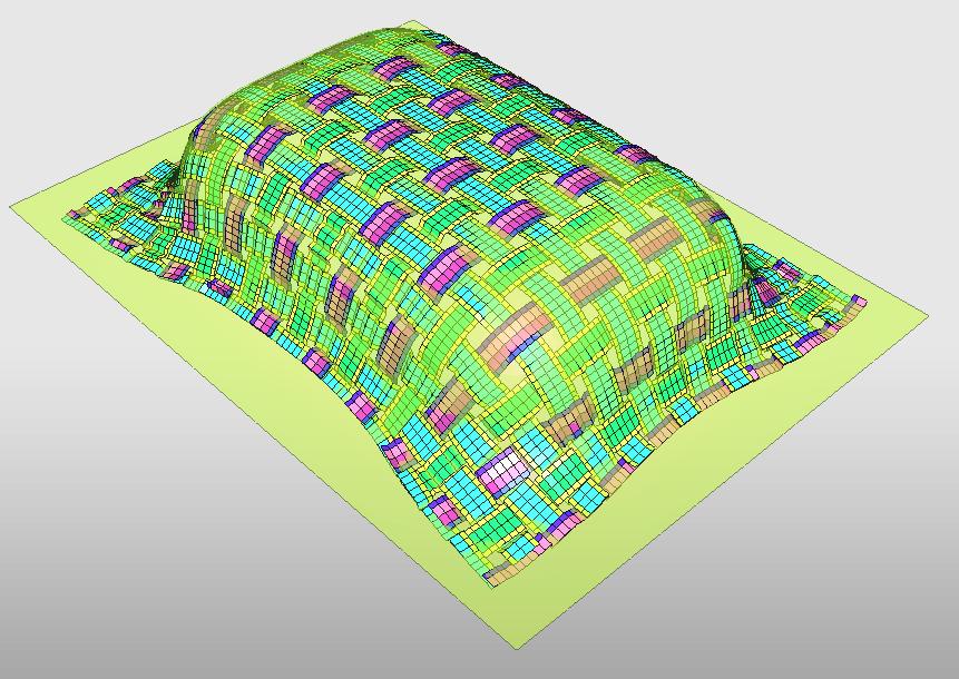
22 Sandwich approach: blank shape during forming

23 Independant Layers approach: blank end shape Sliding effect between layers Due to fiber orientations 0, 45, 90, -45 regarding X axis, the behavior during stamping is different for each layer


24 B-Pillar model: blank end shape Sandwich approach The same compression, tension and shear zones can be observed Wrinkles may also occur Independant Layers approach


 Fiber")


25 B-Pillar model: Fiber Orientations Sandwich approach (0 layer) Fiber orientations are consistent with blank shape Independant Layers approach (layers 45 & 90 )
26 Composite Forming with HyperWorks Modeling approaches B-Pillar model example Hyperform updates Mapping Meso to Macro multiscale approach Draping Conclusions
27 HyperForm 13.0 updates for composite forming Composite available thru User Process tree browser settings Type of modeling selection popup Then HF sets up automatically Contact interfaces tools and blank(s) Contact interface between layers Post-treatment cards in engine

28 HyperForm 13.0 updates for composite forming User Process Tree browser organisation for the sandwich approach User Process Tree browser organisation for the independant layers approach Plies definiton Layers are treated as independant blanks
29 Composite Forming with HyperWorks Modeling approaches B-Pillar model example Hyperform updates Mapping Meso to Macro multiscale approach Draping Conclusions


30 Mapping algorithm Forming side Mapping?? Crash side Target integration points Stamping integration points


31 Fiber directions mapping NEW in HC First & Second fiber directions can be mapped for each layer Angle between fibers is shown as iso-values while displaying the second direction as vector
 on 1 layer of shell elements (MAT25) associated with a 4")
32 Mapping for independant layers approach Target part Composite layers NEW in HC layers of shell elements (MID 58, PID 16) on 1 layer of shell elements (MAT25) associated with a 4 layer sandwitch property (PROP11)


33 Woven fabric forming history influence on crash Reference model Model initialized with fiber directions from forming stage
34 Composite Forming with HyperWorks Modeling approaches B-Pillar model example Hyperform updates Mapping Meso to Macro multiscale approach Draping Conclusions


35 Meso-scopic scale modeling Strip of shells Angle ~90 Angle < 50 E11 >> E22, E33 Contact interface between fibers


36 Coupling from meso to macro thru mapping Model to map and Target mesh Target part after mapping Angle < 55 Re-zoning according to an angle criterion of 55 E = 70%E, G = 70%G etc Second direction after mapping: angle with the first direction


37 Meso-scopic scale approach: improvements in Mapping Volume of fibers Shear angle Rezoned part Rezoning Criteria Rezoning


38 Using a Mesoscale approach within a Macroscale modeling The maximum shear area is modeled at mesoscopic scale Displacements
39 Composite Forming with HyperWorks Modeling approaches B-Pillar model example Hyperform updates Mapping Meso to Macro multiscale approach Draping Conclusions

 versus")
40 Drape Estimator for Composite Fibers Calculate Draping angles Thickness variation Interfaces OptiStruct Nastran HM Drape Estimator (white) versus competition (red)


41 Drape Estimator for Composite Fibers Final part geometry OneStep OneStep result : flattened shape Fiber directions Final part initialised with Material/fiber directions Material/Fiber directions defined on the flat reference shape
42 Composite Forming with HyperWorks Modeling approaches B-Pillar model example Hyperform updates Mapping Meso to Macro multiscale approach Draping Conclusions
43 Conclusions Several works and studies around composite forming with Radioss Reduced input data, simple set up, reasonably fast and accurate Different scales modeling approaches depending on the expected results Influence of forming results on crash simulation results has been shown Mapping with re-zoning allows to take into account material degradation Mapping compatible with sandwitch and multi-layers modeling Validation is in progress
44 Perspectives To validate with benchmarks and experimental comparisons To develop a dual-phase material to model cool and warm resin To validate and compare draping approach with other methods To continue to use mesoscopic modeling thru multi-scale coupling or for macroscopic modeling validation
45 Merci de votre attention!
COMPOSITE DRAPING SIMULATION TO ENHANCE STRUCTURAL ANALYSIS
 COMPOSITE DRAPING SIMULATION TO ENHANCE STRUCTURAL ANALYSIS Paul Van Huffel Altair Engineering, Inc Abstract With composite analysis and optimization on the rise, the accuracy of our assumptions is becoming
3D fabric modelling with hyperworks tool for impact
 3D fabric modelling with hyperworks tool for impact PATTERN FABRIC Karine THORAL PIERRE ktp@cedrem.fr 1 Company Profile CEDREM sarl. Case studies of modeling by FE with hyperworks tools Materials Researches
Modeling of Materials Getting to a Smaller Scale. Dr. Robert N. Yancey Altair Engineering
 Modeling of Materials Getting to a Smaller Scale Dr. Robert N. Yancey Altair Engineering Outline Background Current Research Pre- and Post-Processing Requirements Guiding the Analyst Setting up the Analysis
Agenda. 9:00 Welcome. 1:00 - Computing Utilities. 9:15 - Mechanical Demonstration. 1:30 - CFD Update. 3:00 Break 3:15 ANSYS Customization Toolkit
 Agenda 9:00 Welcome 1:00 - Computing Utilities Introductions What is new at CAEA 9:15 - Mechanical Demonstration CAD connection utilities (within the CAD API) Mechanical setup Rigid Bodies, Joints, contact,
MSC.Patran Laminate Modeler
 MSC.Patran Laminate Modeler PRODUCT LINE MSC.Patran OVERVIEW For the development of optimized laminated structures CAPABILITIES Calculate failure indices Optimize materials, plies, and layups Size zones
Investigating the influence of local fiber architecture in textile composites by the help of a mapping tool
 Investigating the influence of local fiber architecture in textile composites by the help of a mapping tool M. Vinot 1, Martin Holzapfel 1, Christian Liebold 2 1 Institute of Structures and Design, German
FEA of Composites Classical Lamination Theory Example 1
 FEA of Composites Classical Lamination Theory Example 1 22.514 Instructor: Professor James Sherwood Author: Dimitri Soteropoulos Revised by Jacob Wardell Problem Description: A four layer [0/90] s graphite-epoxy
CODE Product Solutions
 CODE Product Solutions Simulation Innovations Glass Fiber Reinforced Structural Components for a Group 1 Child Harold van Aken About Code Product Solutions Engineering service provider Specialised in Multiphysics
ACP (ANSYS Composite Prep/Post) Jim Kosloski
 Jim Kosloski") ACP (ANSYS Composite Prep/Post) Jim Kosloski ACP Background ANSYS Composite PrepPost is an add-on module dedicated to the modeling of layered composite structures. ACP is now included with the Mechanical
ACP (ANSYS Composite Prep/Post) Jim Kosloski ACP Background ANSYS Composite PrepPost is an add-on module dedicated to the modeling of layered composite structures. ACP is now included with the Mechanical
Materials Modelling and Interoperability Siemens PLM Vision
 Materials Modelling and Interoperability Siemens PLM Vision November 2017 Realize innovation. Siemens PLM Simulation & Test Solutions Mission: Help end user industry to manufacture better products more
Coupling between stamping results and crash simulation N. Vallino. European Hyperworks Technology Conference 2010 Versailles , October 28th
 Coupling between stamping results and crash simulation N. Vallino European Hyperworks Technology Conference 2010 Versailles - 2010, October 28th 2 Summary Why coupling stamping results with crash simulation?
Simulation of fiber reinforced composites using NX 8.5 under the example of a 3- point-bending beam
 R Simulation of fiber reinforced composites using NX 8.5 under the example of a 3- point-bending beam Ralph Kussmaul Zurich, 08-October-2015 IMES-ST/2015-10-08 Simulation of fiber reinforced composites
Altair HyperWorks: A Platform for Innovation. Vladimir Obukhov Technical Consultant Altair Engineering GmbH
 Altair HyperWorks: A Platform for Innovation Vladimir Obukhov Technical Consultant Altair Engineering GmbH HyperWorks Desktop Integration Typical FEA Process IMPORT FROM CAD or CAE World CAD CAE 1) GEOMETRY
CHAPTER-10 DYNAMIC SIMULATION USING LS-DYNA
 DYNAMIC SIMULATION USING LS-DYNA CHAPTER-10 10.1 Introduction In the past few decades, the Finite Element Method (FEM) has been developed into a key indispensable technology in the modeling and simulation
Simulation of the Effect of Draw Bead on Drawing Process of Panel Header using Altair Hyperform
 Simulation of the Effect of Draw Bead on Drawing Process of Panel Header using Altair Hyperform Desai Ashutosh Valmik PG Student AISSMS COE PUNE 411001 desaiashutosh11@gmail.com Prof. P.V. Deshmukh Asst.
Modal Analysis of a Steel Frame
 Modal Analysis of a Steel Frame Name: Sushanth Kumareshwar Panchaxrimath Department: Mechanical Engineering Course: Powertrain NVH of Electrified Vehicles Date: 11/26/2016 SUMMARY A dynamic modal analysis
RHEOMOLD ENGINEERING SOLUTIONS LLP
 RHEOMOLD ENGINEERING SOLUTIONS LLP 1 Content Rheomold Services & Capabilities Rheomold Capacity Design Projects executed CAE Projects executed Manufacturing Simulations (Moldflow, Casting & Forming) Customers
The new HyperMesh - Samcef interface.
 The new HyperMesh - Samcef interface. Deployment and industrial applications at Eurocopter. Ronan PITOIS Dynamic systems dpt. Presentation plan Eurocopter overview Stress computation performed in Eurocopter
Improved mapping workflow with HM 11
 Dipl.-Ing.M. Meyer, M. Eng. D. Pielok, Dipl.-Ing. M. Heuse (all Faurecia) Dipl.-Ing. G. de los Rios, Dipl.-Ing. A. Hülsmann (all Altair) 8. November 2011 Content Short introduction on Faurecia Mapping
HyperCrash. A highly-tuned modeling environment for crash analysis and safety evaluation in the HyperWorks simulation framework
 HyperCrash A highly-tuned modeling environment for crash analysis and safety evaluation in the HyperWorks simulation framework Christian Alscher, Giuseppe Resta Altair, Böblingen/Troy, Germany/USA Summary:
Benchmarks for Composite Delamination Using LS-Dyna 971: Low Velocity Impact
 Benchmarks for Composite Delamination Using LS-Dyna 971: Low Velocity Impact Esteban D. Moncayo J. *, Heike Wagner **, Klaus Drechsler** * Dynamore GmbH, Germany ** Institute of Aircraft Design, University
VALIDATION OF LOCAL STITCHING SIMULATION FOR STITCHED NCF PLY STACKS
 THE 19 TH INTERNATIONAL CONFERENCE ON COMPOSITE MATERIALS VALIDATION OF LOCAL STITCHING SIMULATION FOR STITCHED NCF PLY STACKS S. Bel 1 *, A. Margossian 2, D. Leutz 1, U. Beier 2, R. Hinterhoelzl 1, K.
Composite Optimisation of an F1 Front Wing
 Composite Optimisation of an F1 Front Wing Jonathan Heal Senior Stress Engineer, McLaren Racing Ltd McLaren Technology Centre, Chertsey Rd, Woking. GU21 4YH Jonathan.heal@mclaren.com Abstract Formula one
Altair HyperForm. Incremental Stamping Analysis
 Altair HyperForm Incremental Stamping Analysis Altair Engineering Contact Information Web site FTP site www.altair.com Address: ftp.altair.com or ftp2.altair.com or http://ftp.altair.com/ftp Login: ftp
FINITE ELEMENT ANALYSIS OF A COMPOSITE CATAMARAN
 NAFEMS WORLD CONGRESS 2013, SALZBURG, AUSTRIA FINITE ELEMENT ANALYSIS OF A COMPOSITE CATAMARAN Dr. C. Lequesne, Dr. M. Bruyneel (LMS Samtech, Belgium); Ir. R. Van Vlodorp (Aerofleet, Belgium). Dr. C. Lequesne,
4-2 Quasi-Static Fatigue
 1 4-2 Quasi-Static Fatigue Case Description: Example Location: Composite coupon subject to tensile cyclic loading Tutorials > Fatigue > Quasi Static Fatigue Model Description: Nodes: 261; Elements: 224
Model Set up, Analysis and Results of the Inverse Forming Tool in ANSA
 Model Set up, Analysis and Results of the Inverse Forming Tool in ANSA Evlalia Iordanidou, Georgios Mokios BETA CAE Systems SA Abstract With an ongoing aim to reduce the time a model requires to be prepared,
Principal Roll Structure Design Using Non-Linear Implicit Optimisation in Radioss
 Principal Roll Structure Design Using Non-Linear Implicit Optimisation in Radioss David Mylett, Dr. Simon Gardner Force India Formula One Team Ltd. Dadford Road, Silverstone, Northamptonshire, NN12 8TJ,
Metal Forming Automation using LS-OPT
 14 th International LS-DYNA Users Conference Session: Metal Forming Metal Forming Automation using LS-OPT Krishna Chaitanya Kusupudi Whirlpool Corporation, GTEC, Pune, India krishna_c_kusupudi@whirlpool.com
Ply-based composite modeling with the new *ELEMENT_SHELL_COMPOSITE keyword
 Ply-based composite modeling with the new *ELEMENT_SHELL_COMPOSITE keyword Summary Dr.-Ing. Ulrich Stelzmann Dr.-Ing. Matthias Hörmann CADFEM GmbH, Grafing b. München, Germany Because of their superior
Multi-scale Material Modeling Applied from Specimen to Full Car Level using LS-DYNA
 Multi-scale Material Modeling Applied from Specimen to Full Car Level using LS-DYNA Sylvain Calmels e-xstream Engineering Abstract Tomorrow s vehicles architectures will involve an increasing number of
FORMING BENCHMARK FORMING OF A DOUBLE DOME
 FORMING BENCHMARK FORMING OF A DOUBLE DOME (version: March 17, 2005) Benchmark Forum Website: http://www.gtwebsolutions.com/nwbenchmark/index.php Materials Testing Results Website: http://www.mech.northwestern.edu/ampl/benchmark/
Composites for JEC Conference. Zach Abraham ANSYS, Inc.
 Composites for JEC Conference Zach Abraham ANSYS, Inc. 1 Our Strategy Simulation-Driven Product Development Fluid Dynamics Structural Mechanics Explicit Dynamics Low-Frequency Electromagnetics High-Frequency
OptiStruct Optimization-Driven Design
 OptiStruct 14.0 Optimization-Driven Design Drivers for OptiStruct 14.0 5x-35x Faster! New Solutions Design Better Products Solution Enhancements Get Robust Answers More Easily Performance Get Products
Explicit Dynamic Analysis of Bird Strike Simulations and Design Optimization of Composite Aircraft Structures
 Explicit Dynamic Analysis of Bird Strike Simulations and Design Optimization of Composite Aircraft Structures Manoj Susarla Jr Design Engineer Octants Engineering Innovations Dr no 12-3-25,Ayyevari street,
Modeling of Punctual Joints for Carbon Fiber Reinforced Plastics (CFRP) with *MAT_054
 with *MAT_054") Modeling of Punctual Joints for Carbon Fiber Reinforced Plastics (CFRP) with *MAT_054 Christian Liebold 1, David Moncayo 2 1 DYNAmore GmbH, Stuttgart, Germany 2 Daimler AG, Sindelfingen, Germany Abstract
Modeling of Punctual Joints for Carbon Fiber Reinforced Plastics (CFRP) with *MAT_054 Christian Liebold 1, David Moncayo 2 1 DYNAmore GmbH, Stuttgart, Germany 2 Daimler AG, Sindelfingen, Germany Abstract
Nouveautés ANSYS pour le calcul structurel et l impression 3D. CADFEM 2017 ANSYS Additive Manufacturing
 Titelmasterformat Journée Technologique durch AddiPole Klicken bearbeiten Nouveautés ANSYS pour le calcul structurel et l impression 3D Titelmasterformat Structural design with durch ANSYS Klicken bearbeiten
Appendix B: Simulation of the Blade Manufacturing Process
 B-1 Appendix B: Simulation of the Blade Manufacturing Process This appendix discusses the step-by-step process of the modeling of the CX-100 wind turbine blade for the manufacturing process and the resulting
Finite Element Analysis and Optimization of I.C. Engine Piston Using RADIOSS and OptiStruct
 Finite Element Analysis and Optimization of I.C. Engine Piston Using RADIOSS and OptiStruct Vivek Zolekar Student M. Tech. Mechanical (CAD/CAM) SGGSIE&T Nanded - 431 606 Dr. L.N. Wankhade Professor Department
System Level Cooling, Fatigue, and Durability. Co-Simulation. Stuart A. Walker, Ph.D.
 System Level Cooling, Fatigue, and Durability Analysis via Multiphysics Co-Simulation Stuart A. Walker, Ph.D. swalker@altair.com Outline Motivation Presentation of process Presentation of tools Presentation
Release July 2013
 Release 4.5.1 July 2013 For a fast & accurate prediction of the nonlinear behavior of multi-phase materials using Mean-Field homogenization technology. For an accurate prediction of the local/global nonlinear
A Graphical User Interface for Simulating Resin-Transfer-Molding Combining LS-DYNA and OpenFOAM
 A Graphical User Interface for Simulating Resin-Transfer-Molding Combining LS-DYNA and OpenFOAM M. Martins-Wagner 1, M. Wagner 1, A, Haufe 2, C. Liebold 2 1 Ostbayerische Technische Hochschule Regensburg
HyperWorks Desktop Release Notes
 HyperWorks Desktop 12.0.117 Release Notes Introduction HyperWorks HW12.0.117-HWDesktop contains enhancements and bug fixes for HyperMesh, HyperView, HyperGraph and HyperForm. The details are documented
Targeting Composite Wing Performance Optimising the Composite Lay-Up Design
 Targeting Composite Wing Performance Optimising the Composite Lay-Up Design Sam Patten Optimisation Specialist, Altair Engineering Ltd Imperial House, Holly Walk, Royal Leamington Spa, CV32 4JG sam.patten@uk.altair.com
RD-1070: Analysis of an Axi-symmetric Structure using RADIOSS
 RADIOSS, MotionSolve, and OptiStruct RD-1070: Analysis of an Axi-symmetric Structure using RADIOSS In this tutorial, you will learn the method of modeling an axi- symmetry problem in RADIOSS. The figure
Speedup Altair RADIOSS Solvers Using NVIDIA GPU
 Innovation Intelligence Speedup Altair RADIOSS Solvers Using NVIDIA GPU Eric LEQUINIOU, HPC Director Hongwei Zhou, Senior Software Developer May 16, 2012 Innovation Intelligence ALTAIR OVERVIEW Altair
APPROACHING A RELIABLE PROCESS SIMULATION FOR THE VIRTUAL PRODUCT DEVELOPMENT
 APPROACHING A RELIABLE PROCESS SIMULATION FOR THE VIRTUAL PRODUCT DEVELOPMENT K. Kose, B. Rietman, D. Tikhomirov, N. Bessert INPRO GmbH, Berlin, Germany Summary In this paper an outline for a strategy
Crashbox Tutorial. In this tutorial the focus is on modeling a Formula Student Racecar Crashbox with HyperCrash 12.0
 Crashbox Tutorial In this tutorial the focus is on modeling a Formula Student Racecar Crashbox with HyperCrash 12.0 (Written by Moritz Guenther, student at Altair Engineering GmbH) 1 HyperMesh* 1. Start
2014 Autodesk. Helping you make great products
 Helping you make great products Autodesk Solution for Digital Prototyping Autodesk supports a comprehensive set of offerings and a broad strategy in simulation that indeed meets the needs of companies
Virtual Try Out and Process Optimization for an Innovative Conic Poles Production Concept
 8 th International LS-DYNA Users Conference Methods Development Virtual Try Out and Process Optimization for an Innovative Conic Poles Production Concept A. Anglani, G. Papadia Department of Innovation
Free-Shape Optimization of a 3-D Bracket using the Free-shape Method
 Free-Shape Optimization of a 3-D Bracket using the Free-shape Method In this exercise, shape optimization on a solid bracket model will be performed using the Free- Shape optimization method. The objective
Using Computer Aided Engineering Processes in Packaging Design Development
 Using Computer Aided Engineering Processes in Packaging Design Development Jose Martinez, Miguel Angel Garcia Jose Luis Moreno Vicencio & Hugo Miranda Mabe, Mexico Mahesh Patel, Andrew Burkhalter, Eric
Digital Fabric Mechanics Analyzer
 Digital Fabric Mechanics Analyzer Youqi Wang Department of Mechanical &Nuclear Engineering Kansas State University Manhattan, KS 66506 Applications Textile process simulation Static Simulation (Weaving)
COMPLIANCE MODELLING OF 3D WEAVES
 6 TH INTERNATIONAL CONFERENCE ON COMPOSITE MATERIALS COMPLIANCE MODELLING OF 3D WEAVES Prasad Potluri *, Andrew Long **, Robert J Young *, Hua Lin **, Yat-Tarng Shyng *, A Manan * * School of Materials,
Fast Tracking Rail Vehicle Design
 Fast Tracking Rail Vehicle Design Nigel Randell Senior Engineer Crash Safety, Bombardier Transportation UK Ltd Litchurch Lane, Derby, DE24 8AD, UK nigel.randell@uk.transport.bombardier.com Jérôme Rousseau
About DatapointLabs &
 About DatapointLabs & Matereality Hubert Lobo DatapointLabs Accurate FEA of Engineering Plastics Seminar October 14, 2014 2014 CAE Associates + technical center for materials software for materials Materials
Simulation of laminate composite space antenna structures
 Sairam Prabhakar Simulation of laminate composite space antenna structures Femap Symposium 2014 May 14-16, Atlanta, GA, USA FEMAP SYMPOSIUM 2014 Discover New Insights Agenda Background Workflows for modeling
Composite Materials Multi Objective Optimization using ANSA, META and modefrontier
 Composite Materials Multi Objective Optimization using ANSA, META and modefrontier Introduction As the composite materials market expands and more applications appear in the automotive, aerospace and naval
Modelling and Simulation of Damage in Woven Fabric Composites on Meso-macro Level using the Independent Mesh Method
 Nationaal Lucht- en Ruimtevaartlaboratorium National Aerospace Laboratory NLR Modelling and Simulation of Damage in Woven Fabric Composites on Meso-macro Level using the Independent Mesh Method W.M. van
Reducing overdesign with predictive performance and producibility simulation
 American Society of Composites 29 th technical Conf., 16 th US-Japan Conf. on Composite Materials, San Diego, USA, September 10, 2014 Reducing overdesign with predictive performance and producibility simulation
Tutorial 10: Composite impact using multi-layered shell elements
 Tutorial 10 Impact of a Composite Disc using Multilayered Shell Elements Problem description Outline Analysis type(s): Element type(s): Materials law(s): Model options: Key results: Prepared by: Date:
Finite Element Modeling for Numerical Simulation of Multi Step Forming of Wheel Disc and Control of Excessive Thinning
 Finite Element Modeling for Numerical Simulation of Multi Step Forming of Wheel Disc and Control of Excessive Thinning Prashantkumar S.Hiremath 1,a, Shridhar Kurse 2,a, Laxminarayana H.V. 3,a,Vasantha
On the Optimization of the Punch-Die Shape: An Application of New Concepts of Tools Geometry Alteration for Springback Compensation
 5 th European LS-DYNA Users Conference Optimisation (2) On the Optimization of the Punch-Die Shape: An Application of New Concepts of Tools Geometry Alteration for Springback Compensation Authors: A. Accotto
Failure of Notched Laminates Under Out-of-Plane Bending Phase VII
 Failure of Notched Laminates Under Out-of-Plane Bending Phase VII Fall 2014 Meeting Mitchell Daniels, Levi Suryan, & John P. Parmigiani, Oregon State University Motivation and Key Issues Failure of Notched
Release April 2013
 Release 4.4.1 April 2013 For a fast & accurate prediction of the nonlinear behavior of multi-phase materials using Mean-Field homogenization technology. For an accurate prediction of the local/global nonlinear
Release Notes January 2016
 Release Notes 2016.0 January 2016 p. 2 p. 3 p.4 p. 6 p. 7 p. 9 - p.10 1 P a g e C o p y r i g h t e - X s t r e a m e n g i n e e r i n g, 2 0 1 6 New Capabilities Multi-layer failure controls for SFRP
Mechanical Behaviors of Non-Crimp Fabric Composites Based on Multi-scale Analysis
 Mechanical Behaviors of Non-Crimp Fabric Composites Based on Multi-scale Analysis T.Kurashiki 1 *, K.Hamada 1, S.Honda 1, M.Zako 1, S.V.omov 2, and I.Verpoest 2 1 Dept. of Management of Industry and Technology,
Dipl.-Ing. Andreas Knote
 Dipl.-Ing. Andreas Knote German Aerospace Center DLR, Institute of Composite Structures and Adaptive Systems Lilienthalplatz 7 38108 Braunschweig Phone +49 531 295-3289 andreas.knote@dlr.de Education:
LAMINATE TOOLS TUTORIAL
 LAMINATE TOOLS TUTORIAL Laminate Tools Tutorial 2/62 Anaglyph Ltd C O N T E N T S Introduction... 5 The basics... 5 Model control...6 View modes...6 Model description... 8 Draping... 10 Create a Material...10
CAE Data Management and Quality Assessment of LS-DYNA Crash Models using V-CESS
 4 th European LS-DYNA Users Conference LS-DYNA Environment I CAE Data Management and Quality Assessment of LS-DYNA Crash Models using V-CESS Authors: Matthias Eick, Dr. Lars Fredriksson, Dr. Jochen Seybold
Neuerungen in LS-PrePost für das Pre- und Postprocessing von Composites
 Neuerungen in LS-PrePost für das Pre- und Postprocessing von Composites Thomas Klöppel DYNAmore GmbH Stuttgart Anders Jernberg DYNAmore Nordic AB Linköping LS-PrePost für Composites - Thomas Klöppel -
Closing the Gap between Process- and Crash Simulation for Composite Materials
 Closing the Gap between Process- and Crash Simulation for Composite Materials Ch. Liebold 1, H. Finckh 2, T. Günther 3, A. Haufe 1 1 DYNAmore GmbH, Stuttgart, Germany 2 Deutsches Institut für Textil- und
Topology Optimization of Flaring Tool Using OptiStruct
 Topology Optimization of Flaring Tool Using OptiStruct Rahul Nanche Engineer CAE Emerson Innovation Center Hinjewadi,Pune 411057 Sachin Magdum Lead Engineer Emerson Innovation Center Hinjewadi,Pune 411057
FE surface mesh creation on the middle surface of a solid described model. Nodal Thickness is calculated for each shell element
 BETA CAE Systems S.A. Kato Scholari, Thessaloniki GR-57500, Epanomi Greece tel: +30-2392-021420 fax: +30-2392-021828 email: ansa@beta-cae.gr url: http://www.beta-cae.gr New software version release announcement
Abaqus-SwiftComp GUI
 Abaqus-SwiftComp GUI Version 1.2.2 User s Manual April 21, 2017 Bo Peng Su Tian Lingxuan Zhou Wenbin Yu ii Table of Contents 1 GENERAL INFORMATION...3 1.1 Installation and Get Started...3 1.2 Abaqus-SwiftComp
International Journal of Scientific & Engineering Research, Volume 8, Issue 4, April-2017 ISSN
 ISSN 2229-5518 1058 Finite Element Analysis of an Excavator Arm CAE Tool Asit Kumar Choudhary, Gian Bhushan Abstract: Background: Excavators are earth moving equipment and the main component for completing
A NUMERICAL SIMULATION OF DAMAGE DEVELOPMENT FOR LAMINATED WOVEN FABRIC COMPOSITES
 A NUMERICAL SIMULATION OF DAMAGE DEVELOPMENT FOR LAMINATED WOVEN FABRIC COMPOSITES Tetsusei Kurashiki 1, Yujiro Momoji 1, Hiroaki Nakai 1, and Masaru Zako 1 1 Department of Management of Industry and Technology,
Sheet Metal Forming Simulation for Light Weight Vehicle Development
 Sheet Metal Forming Simulation for Light Weight Vehicle Development Die Design & Simulation Software Experience Arthur Tang May 29, 2013 Grand Rapids, MI Industry Demand for Fuel Efficient Vehicles The
Composites Seminar Seattle. Sean Harvey March 16, 2012
 Composites Seminar 2012 - Seattle Sean Harvey March 16, 2012 1 Agenda 09:30-10:00 Registration 10:00-10:30 Incorporating Basic FEM Concepts in a Introductory Composites Analysis Course Composites Failure,
CHAPTER 4 CFD AND FEA ANALYSIS OF DEEP DRAWING PROCESS
 54 CHAPTER 4 CFD AND FEA ANALYSIS OF DEEP DRAWING PROCESS 4.1 INTRODUCTION In Fluid assisted deep drawing process the punch moves in the fluid chamber, the pressure is generated in the fluid. This fluid
Modelling Flat Spring Performance Using FEA
 Modelling Flat Spring Performance Using FEA Blessing O Fatola, Patrick Keogh and Ben Hicks Department of Mechanical Engineering, University of Corresponding author bf223@bath.ac.uk Abstract. This paper
Fundamentals of Modeling with Simcenter 3D Robin Boeykens
 Fundamentals of Modeling with Simcenter 3D Robin Boeykens robin.boeykens@siemens.com Realize innovation. 3D CAE for the digital twin Simcenter 3D Page 2 Simcenter 3D Engineering Desktop Simcenter 3D Engineering
MSC/PATRAN LAMINATE MODELER COURSE PAT 325 Workbook
 MSC/PATRAN LAMINATE MODELER COURSE PAT 325 Workbook P3*V8.0*Z*Z*Z*SM-PAT325-WBK - 1 - - 2 - Table of Contents Page 1 Composite Model of Loaded Flat Plate 2 Failure Criteria for Flat Plate 3 Making Plies
Experimental Evaluation and Consideration of Numerical Method of Zanchor CFRP Laminates
 Experimental Evaluation and Consideration of Numerical Method of Zanchor CFRP Laminates Yuichiro Aoki, Yosuke Nagao, Takashi Ishikawa Advanced Composite Technology Center, Japan Aerospace Exploration Agency
An alternative approach to automotive door seal design using HyperStudy
 An alternative approach to automotive door seal design using HyperStudy Maxime Le Moine, Mahmoud Oumohand Maxime Le Moine Cooper-Standard Sales : 2,5 Md$ Employees : 20 000 Locations : 55+ NVH Fluid Sealing
NON-PARAMETRIC SHAPE OPTIMIZATION IN INDUSTRIAL CONTEXT
 NON-PARAMETRIC SHAPE OPTIMIZATION IN INDUSTRIAL CONTEXT Michael Böhm, Peter Clausen FE-DESIGN GmbH, Paris, April 3rd, 2012 Overview Introduction / FE-Design Optimization in Industry and Requirements Shape
For Structural analysis, Thermal analysis, Mechanisms simulation and other Fields
 What is SAMCEF Field? An Integrated Environment for CAE Modeling, Analysis and Results processing For Structural analysis, Thermal analysis, Mechanisms simulation and other Fields SAMTECH s.a. - www.samcef.com
Example 24 Spring-back
 Example 24 Spring-back Summary The spring-back simulation of sheet metal bent into a hat-shape is studied. The problem is one of the famous tests from the Numisheet 93. As spring-back is generally a quasi-static
Optimized Composite Design Methodologies that Enable Rapid Change
 Optimized Composite Design Methodologies that Enable Rapid Change Realize innovation. Agenda Multi Ply Introduction Application Rapid Change Acquired by Siemens PLM Software 2011 Leading composite design
Use of Topography Optimization in Developing Bending Pattern of Compressor Mounting Plate in Refrigerator
 ISSN 2395-1621 Use of Topography Optimization in Developing Bending Pattern of Compressor Mounting Plate in Refrigerator #1 Dayabhushan S. Thorat, #2 Akash.R.Suryavanshi 1 dayabhushanthorat@gmail.com 2
Coupled Simulation of the Fluid Flow and Conjugate Heat Transfer in Press Hardening Processes
 13 th International LS-DYNA Users Conference Session: Metal Forming Coupled Simulation of the Fluid Flow and Conjugate Heat Transfer in Press Hardening Processes Uli Göhner 1), Bruno Boll 1), Inaki Caldichouri
Consideration of Damage Accumulated During the Forming Process in Crash Simulations
 Consideration of Damage Accumulated During the Forming Process in Crash Simulations Ashutosh Patil FCA US LLC GDIS2018 Damage accumulated during the forming process Contributors: Ashutosh Patil 1*, Hamid
Predicting the mechanical behaviour of large composite rocket motor cases
 High Performance Structures and Materials III 73 Predicting the mechanical behaviour of large composite rocket motor cases N. Couroneau DGA/CAEPE, St Médard en Jalles, France Abstract A method to develop
Appendix P. Multi-Physics Simulation Technology in NX. Christian Ruel (Maya Htt, Canada)
") 251 Appendix P Multi-Physics Simulation Technology in NX Christian Ruel (Maya Htt, Canada) 252 Multi-Physics Simulation Technology in NX Abstract As engineers increasingly rely on simulation models within
251 Appendix P Multi-Physics Simulation Technology in NX Christian Ruel (Maya Htt, Canada) 252 Multi-Physics Simulation Technology in NX Abstract As engineers increasingly rely on simulation models within
ixcube 4-10 Brief introduction for membrane and cable systems.
 ixcube 4-10 Brief introduction for membrane and cable systems. ixcube is the evolution of 20 years of R&D in the field of membrane structures so it takes a while to understand the basic features. You must
5TH ANSA & META INTERNATIONAL CONFERENCE AN INSIGHT TO APPLICATIONS BASED ON ANSA TO THE BMW CAE PROCESSES
 Josef Fürfanger, 5.6.2013 5TH ANSA & META INTERNATIONAL CONFERENCE AN INSIGHT TO APPLICATIONS BASED ON ANSA TO THE BMW CAE PROCESSES AGENDA 1 History of BMW BETA Cooperation 2 Mapping Deep-Drawing Simulation
NX Advanced Simulation: FE modeling and simulation
 Advanced Simulation: FE modeling and simulation NX CAE Benefits Speed simulation processes by up to 70 percent Increase product quality by rapidly simulating design trade-off studies Lower overall product
Turn around time reduction
 Turn around time reduction in early attribute assessments using latest software tools like SFE CONCEPT, Perl and HyperMesh Jörgen Hilmann, Ford of Europe, Basic Design Safety Hans Zimmer, SFE GmbH President
One step forming simulation with HyperForm
 2009-11-03 One step forming simulation with HyperForm AGENDA 1. ISRINGHAUSEN 2. Simulation in development process 4. Optimization of blank size 5. Mapping of forming results 6. Conclusion 1. ISRINGHAUSEN
Concept Evaluation and Optimization Tool for Rear Twist Beam Axles. Guillaume LAURENT ThyssenKrupp Sofedit
 Concept Evaluation and Optimization Tool for Rear Twist Beam Axles Guillaume LAURENT Sofedit CONTENT Abstract Sofedit The problem : definition of a twist beam The HyperMesh process : creation of the model