Preface. GSK983Ma User Manual divides into three parts, that is, Programming, Operation and Appendix.
|
|
|
- Marybeth Lloyd
- 5 years ago
- Views:
Transcription
1 This user manual describes all proceedings concerning the operations of this CNC system in detail as much as possible. However, it is impractical to give particular descriptions for all unnecessary or unallowable system operations due to the manual text limit, product specific applications and other causes. Therefore, the proceedings not indicated herein should be considered impractical or unallowable. This user manual is the property of GSK CNC Equipment Co., Ltd. All rights are reserved. It is against the law for any organization or individual to publish or reprint this manual without the express written permission of GSK and the latter reserves the right to ascertain their legal liability.
2 GSK983Ma Milling Machine Center CNC System User Manual Preface Your Excellency, It s our pleasure for your patronage and purchase of this GSK983Ma Milling machining center CNC system made by GSK CNC Equipment Co., Ltd. GSK983Ma User Manual divides into three parts, that is, Programming, Operation and Appendix. Special prompt: 24V switch power box matched with the system is the special power offered by our company. User can not use the power to other purpose. Otherwise, the enormous danger may occur! II
3 Safty Caution Safty Caution! Accident may occur by improper connection and operation!this system can only be operated by authorized and qualified personnel. Please carefully read this manual before using! Refer to user manual issued by the manufacturer carefully before installing, programming and operating this product, and the relative operation should be performed based upon the user manual strictly. III
4 GSK983Ma Milling Machine Center CNC System User Manual Statement In this manual we have tried as much as possible to describe all the various matters. However, we cannot describe all the matters which must not be done, or which cannot be done, because there are so many possibilities. Therefore, matters which are not especially described as possible in this manual should be regarded as impossible Notice The product function and qualification (such as the accuracy, speed) described in this manual is only for this product, which is installed the CNC machine of this product. The actual function configuration and technical capacity are determined by the setting of the manufacturer. The system is matched with the standard operation panel, but its function of each key is defined by the PLC program (ladder diagram). It is very important to note that the function of the key in this manual is described for the standard PLC program! Refer to the manual issued by the manufacturer for the function of each key on the operation panel and the meaning. IV
5 Cautions Cautions Transportation and storage Do not pile the carton more than six layers. Do not climb, stand or place the heavy on the carton. Do not drag or move the production using the cable connected with the production. Do not bump the carton or scratch the panel and the display screen. The product packing should be avoid the damp, sun and rain. Checking Confirm whether it is your purchased product after opening the packing. Confirm whether the product is being damaged during transporting. Confirm whether the spare parts are completed or being damaged. If the unconfirmed type, the lack of accessories or the damage of transportation may occur, touch our company freely. Wiring The wiring or checking should be performed with the professional. Refer to the Connection Manual for the wiring. The product should be grounded, and the grounding resistance should be less than 0.1Ω. The neutral line (zero line) can not be replaced by the grounding. The wiring should be correct and firm, so that the product malfunction or undesired result may occur. The surge absorber diode connected with this product should be connected in the specified direction, or the product may be damaged. The power should be cut off when Inserting or pulling out the plug or opening the machine of the product Detection The man who is the professional can be detected the machine. The power should be cut off before detecting or repairing or changing the elements. Checking the malfunction when the short-circuit or the overloading occurs, it can be started after the malfunction is eliminated. Never attempt to turn on/off the product frequently, if you want to start it again after the power is turned off, it is necessary to wait for 1min at least. V
6 GSK983Ma Milling Machine Center CNC System User Manual Security Responsibility Security responsibility for manufacturer Manufacturer should be take responsibility for the danger of the motor and the accessories which have been eliminated and/ or controlled in design and in structure. Manufacturer should be take responsibility for the security of the motor and accessories. Manufacturer should be take responsibility for use information and suggestion offered to the user. Security responsibility for the user User should be know and understand about the content for security operation by learning and training the security operation of the motor. User should be take responsibility for the security and danger about the increase, change or original motor modification or accessory by themselves. User should be take responsibility for operating, adjusting, maintaining, installing and storing the products without following the descriptions of this manual, All specifications and design are subject to change without further notice. This manual is reserved by final user. Sincere thanks for your friendly patronage for the products made by GSK CNC Equipment Co., Ltd. Chinese version of all technical documents in Chinese and English languages is regarded as final. VI
7 List List Programming Programming...1 Chapter One General GENERAL CAUTIONS FOR READING THIS MANUAL... 1 Chapter Two Specification...3 Chapter Three Programming WHAT IS PROGRAMMING PROGRAM STRUCTURE Block Program Word Input format Decimal point programming The maximum command value Program number Sequence number Skip to optional block DIMENSION WORD Controlled axis Setting unit The least input increment and the least movement unit folds input unit The maximum stroke Program origin and coordinate system The coordinate system and the machining start point Workpiece coordinate system Reference (position) point Absolute and incremental commands FEED FUNCTION (F FUNCTION) Rapid traverse rate Cutting Feedrate Feedrate decelerates to 1/ Synchronous feed (feed/rev.) F1-digit Feed Automatic acceleration/deceleration Automatic Corner Modification The automatic modification of inner corner The change of inner side arc cutting PREPARATION FUNCTION (G FUNCTION) Plain Selection (G17, G18, G19) Positioning (G00) Single Direction Positioning (G60) Linear interpolation (G01) Circular Interpolation (G02, G03) Circular interpolation without an additional axis Arc interpolation with additional axis Sine curve interpolation Thread Cutting (G33) Automatic reference position return (Reference position G27~G30) Reference position return check (G27) Automatically return to the reference position (G28) Return from the reference position automatically (G29) nd, 3 rd and 4 th reference position return (G30) Dwell (G04) VII
8 VIII GSK983Ma Milling Machine Center CNC System User Manual Exact stop check (G09) Exact stop check (G60) and cutting mode (G64) Coordinate system setting (G92) Workpiece coordinate system (G54~G59) Workpiece coordinate system changes by the program command Automatic coordinate system setting Inch/Metric conversion (G20, G21) Stored stroke limit (G22, G23) Skip Function (G31) COMPENSATION FUNCTION Tool length compensation (G43, G44, G49) Tool position offset (G45~G48) Cutter compensation (G40~G42) The function of cutter compensation Offset value (D code) Offset vector Plane selection and vector G40,G41 and G Details of cutter compensation C Functions D and H External tool offset Enter offset value from the program (G10) Scaling (G50, G51) Coordinate system rotation (G68, G69) Format Relationships with other functions Parameter In the case of the command repetition THE FUNCTION OF CYCLE MACHINING The function of the external operation Canned cycle (G73, G74, G76, G80~G89) the repetition of the canned cycle The initial point and point R in the canned cycle (G98, G99) Rigid tapping cycle (G180, G184) Brief Command format Explanation Limitation Examples SPINDLE FUNCTION (S FUNCTION), TOOL FUNCTION (T FUNCTION), MISCELLANEOUS FUNCTION (M FUNCTION), THE 2 ND MISCELLANEOUS FUNCTION (B FUNCTION) Spindle function (S function) S2 digit S4 digit Constant surface speed control Command method Spindle speed rate The clamping of the Max. Spindle speed Rapid feedrate (G00) Tool function (T function) Miscellaneous function (M function) The 2nd Miscellaneous Function (B function) SUB-PROGRAM The Manufacture of the Sub-program The Performance of the Sub-program Special usage USER MACRO PROGRAM General Brief...146
9 List Variable The Description of the Variable The Notation of the Variable Undefined Variable The Display and Setting of the Variable Value Type of the Variable Local Variable # 1~# Common variable #100~ #149, #500~ # System Variable (It is used for the user Macro program B) Operation command the Define and Replacement of the Variable The Add Operation Multiply Operation (The selection of the Macro B) Function (Macro program B) Compound Operation Operation sequence change by the [ ] Accuracy Some Cautions for reducing the accuracy Control command Branch (GOTO) Repeat the WHILE (Macro program B) The Compilation of the User Macro Program Body and Memory The Compilation of the User Macro Program Body The Memory of the User Macro Program Body Macro Program Statement and NC Statement Macro Call command Simple Call Modal call Multiple Call Multiple Modal Call Macro Program Call by G code Call the Sub-program by M Code Call the Macro Program by M Code Sub-program Call by the T code Decimal Position of the Argument M98 (Sub-program Call) and G65 (Calling the different between the Macro program bodies) The Nesting and Local Variables of User Macro The Relationships with Other Functions Special Codes and Words Used in User Programs Restrictions The Description of the P/S Alarm Examples of User Macro Groove Machining External Output Command Open command: POPEN Data Output instruction BPRNT DPRNT Close Instruction PCLOS Necessary Setting for Using the Function Cautions Macro interruption function (Macro B) TOOL LIFE MANAGEMENT Setting of the Tool Groups Specification in the Machining process Performance of the Tool Life Management The Calculation of the Tool Life The Signals Both the Tool Change and Tool Change Reset New Tool Selection Signal IX
10 GSK983Ma Milling Machine Center CNC System User Manual Tool Skip Signal The Display and Input of the Tool Data The Display and Modification of the Tool group Number The display of tool life data during the execution of machine program Presetting of the Tool Life Counter Other Cautions THE INDEXING FUNCTION OF THE INDEX WORKTABLE Instruction method Input Unit Absolute / incremental instruction Concurrently Controlled Axes The Minimum Movement Unit: degree/pulse Feedrate The Clamping and Release of the Indexing Worktable JOG/Step/MPG Other Cautions Chapter Four Operation POWER ON/OFF Power ON Power OFF PROGRAM LOCK RELATED OPERATIONS TO MACHINE PANEL Machine Panel Emergency Stop (red) Mode Selection Operations Related to Manual Operation Jog Feed Handle Feed (MPG) Manual Absolute Value Manual Reference Point Return (reference position) Related Operations in Automatic Running Start Automatic Running Stop Automatic Running Auto Mode Storage area capacity of executed program in AUTO mode Transmit machining program of program storage in Auto mode by USB interface Transit related parameter of machining program in memory by USB interface Transmit processing program from U disk to the memory by USB interface Output processing program from program memory to U disk by USB interface DNC Running Capacity of DNC storage area and related parameter of USB interface Transmit processing program to DNC storage area by USB interface Select processing program in DNC storage area to perform DNC machining Single Block Restart after Feed Hold or Stop Manual Operation in Automatic Running MDI Operation in Automatic Running Skip Over a Block Feedrate Override Dry Run Machione Lock M.S.T. Lock Key Display Lock Mirror Image Rapid Traverse Override Retrieval Function of External Workpiece Number MPG (manual pulse generator) Interruption MPG Interruption Movement of Manual Insertion X
11 List Manual Spindle Function Manual Auxiliary Function DISPLAY AND OPERATION OF THE NC UNIT WITH LCD CHARACTER DISPLAYER State Display Key Input Display of Program Number and Sequence Numbers Alarm Display (functional key ALARM ) Operation Information (the content of external alarm message) Current Position Display and Reset (functional key POSITION ) Display of Command Value (functional key COMMAND ) Setting (functional key SETTING ) Display and Setting of Input, Output, etc Display and Setting of User Macro Program Variables MDI Operation (functional key COMMAND ) MDI Start and Running Reset Offset of the Tool Position Setting and Display of Workpiece Origin Point Offset The method of Measuring Tool Length Program Display (Functional key PROGRAM) Program Number Retrieving (functional key PROGRAM) Input a Single Program File Input Program File with Multiple Programs Input Programs by Keys Deletion of a Program Deletion of All Programs Output a Program Output All Programs Sequence Number Search Restart the Program Comparison and Stop Function for Block Input Offset Value (any functional key) Output Offset Value(functional key: OFFSET) Display Parameter (functional key:parameter ) Program Edit (functional key:parameter ) Word Scanning Word Search Address Search Methods of Returning to the Beginning of A Program Word Insertion (valid when the program lock is ON) Word Alteration (Valid when the program lock is ON) Insertion and Alteration of Words, Blocks and Strings (Active when program lock is ON) Word Deletion (valid when the program lock is ON) Deletion of the Contents before EOB Deletion of Blocks (active when the program lock is ON) Contents Sorting for the Memory Display of All Stored Program Numbers Edit of User Macro Program (valid when program lock is ON) Background Edit (valid when program lock is ON) Display of Running Time Menu Switch Function Operation for LCD Soft Functional Key Introduction Display Direct Input Measured Offset Value of the Workpiece Origin Measure Function of Workpiece Coordinate System Input/Output of NC Parameter XI
12 GSK983Ma Milling Machine Center CNC System User Manual Output of NC Parameter Input of NC Parameter GRAPHIC FUNCTION Display Type of The Graphic Graphic Parameter Setting The Meaning of Graphic Parameter Program Name Drafting, Tool Path Coordinate System Range (maximum), (minimum) Scaling Rotation Angle Start Point Drafting APPENDIX Appendix 1 System Version Display Appendix 2 G Codes List Appendix 3 Range of Command Values Least input increment Appendix 4 Nomographs Appendix 5 Parameters Appendix 6 Alarm List Appendix 7 Status when Turning Power on, Reset and Cleared Appendix 8 Stored Pitch Error Compensation Function Appendix 9 Operation List Appendix10 Program Lock Appendix 11 USB Interface Parameter Transfer Operation Appendix 12 System Clock Setting and PLC Programming XII
13 Chapter One General Programming Chapter One General 1.1 General GSK983Ma Milling machining center CNC system (The following are abbreviated to System ), which is a medium and high grade manufactured goods with high speed, high accuracy, high stability, and high cost performance. It has been developed base on the stable and reliable and the market requirement and the updated technical development by the GSK CNC Equipment Company. This horizontal type/vertical type installation of this system adopts the 8.4 inch/10.4 inch HR, hi-lite LCD screen separately. The system uses the full paster automatic product technology and built-in PLC. The operating interpolation is distributed processing by the multiply high-speed microprocessors, which owns the treatment capacity for 500 blocks per second. The special hardware circuit is externally connected the raster rule, which can be controlled of the position full-close. It has the boundary CNC alarm detecting function, which is used for the serial high-speed, high accuracy, Hi-Rel. 1.2 Cautions for Reading this Manual The capacity of the CNC machine are determined by the CNC system, machine structure, strong current control and the servo system (the mechanical operation pane included), this manual is only described for the GSK983Ma CNC system. This manual is introduced the function (Selection function included) of the system with detailed, but the actual device is not included all the selection function. The function of the CNC system is not only determined by the NC, but also the mechanical part, the strong circuit of the machine side, servo system and the machine operator panel. It is very hard to describe the whole functions of the system, programming and operation thoroughly; it is only expressed from the angle of the system. 1
14 GSK983Ma Milling Machine Center CNC System User Manual The specification of the operation panel, the capacity of the CNC machine, the machine programming and operation method of the character CNC machine are performed by referring the manual issued by the manufacturer. Note: The notes are described for some items. However, when the notes without any expresses are described in this manual, just skip the notes until you return to read it again after finishing this manual, it is very easy to understand for this manual. 2
15 Chapter two Specification Chapter Two Specification No. of item Name 1 Controlled axes 2 No. of simultaneously controlled axes 3 Increment system Specification Standard: 3 axes (X, Y and Z) (It can be set to the 4 th axis or the 5 th axis based on the order. The address of 4 th is selected from A, B, C, U, V and W, the 4 th axis is straight line axis or rotation one which is set by parameter; and the address of the 5 th axis is selected from U, V, W, A, B and C, the 5 th axis is straight line axis or the rotation one which is set by parameter, too). The standard is 3 axes and 3-linkage simultaneously. (It can be set to the 4 axes and 3-linkage, 4 axes and 4-linkage, 5 axes and 3-linkage and 5 axes and 4-linkage base on the order). Note: The functions, such as the rigid tapping and the feed per revolution, can not be used by the 5 axes. The least setting increment 0.001mm inch The least input increment 0.001mm inch The least input increment by metric based on the parameter setting is 0.01mm. 4 Digit check device Pulse encoder 5 The Max. command value 6 Input format 7 Decimal point programming 8 Rapid traverse ± mm ± inch ± Use the formats, such as, changeable block, changeable character and the changeable address. The digit can be inputted with the decimal point, the addresses with decimal point: X, Y, Z, A, B, C, U, V, W, I, J, K, Q, R and F. The axis direction speed is up to m/min or 2400inch/min. The rapid traverse speed can be modified into F0, 25%, 50% and 100% using the rapid traverse override (selection). The feedrate can be set within the following range: 1mm/min ~ 9 Cutting feedrate 30,000mm/min, the upper limited speed of cutting feed 0.01inch/min~ inch/min can be set by the parameter. The feedrate override 10% is regarded as a gear which can be selected a feedrate within the 3
16 GSK983Ma Milling Machine Center CNC System User Manual range of 0~200%, the unit of feedrate set by parameter can be Automatic 10 acceleration/decele ration 11 Absolute/increment value command 12 Coordinate system setting (G92) 13 Positioning (G00) 14 Linear interpolation (G01) 15 Buffer register 16 Dwell (G04) 17 Exact stop check (G09) Checking mode of 18 exact stop/cutting mode (G61, G64) 19 Miscellaneous function (M2 digit) 20 Dry run modified into 0.01 mm/min, mm/min or 0.001inch/min. The linear acceleration or deceleration mode can be used at the rapid traverse rate regardless of the manual or Auto to shorten the positioning time. Either the absolute programming or increment programming can be selected by the G code. G90: Absolute value programming G91: Incremental value programming The command value followed with the G92 can be used to set a coordinate system, the tool position coordinate value is the command value of this coordinate system. Each axis can separately and rapidly move to the end then stops by specifying G00, and whether the machine can be performed the in-position (whether the machine is reached the specified position) check by the parameter setting. Use the G01 code, the linear interpolation can be performed based on the feedrate specified by F code. The next block can be read to the buffer register in advance before the former block is performed. In this case, avoid the intermittence of NC command because the time for reading. When the data is inputted to the buffer register, the BUF is displayed at the lower right of LCD. The next block movement can be delayed using the G04 code. The delay time can be specified by the address P or X. Specify a block of G09, it decelerates to 0 when the block ends, and then performs the following block after positioning. If the G61 is specified, the movement command followed with the G61 decelerates to 0 at the end of each block, and then performs the following block after positioning. If the G64 is specified, the movement command followed with the G64 other than the position does not decelerate but perform the following block immediately, generally, it is for cutting mode. The command after the address M followed 2-digit can be controlled for the ON/OFF signal of the machine side. Only one M code can be specified in a block. In the dry run mode, the feedrate becomes JOG. The rapid traverse holds invariable in G00 command, the rapid traverse override (selection) is still valid. Whether the rapid feedrate is run based 4
17 Chapter two Specification 21 Interlocking upon the dry run which is determined by the parameter setting. Each axis can be separately forbidden the feed of the commanded axis, if any commanded axis is added an interlocking during movement, all of the axes of machine may decelerate and then stops. The machine accelerates then starts as long as the interlocking releases. 22 Single block One block command can be performed once. 23 Optional block skip External mirror image Manual absolute ON/OFF Miscellaneous function lock 27 Machine lock 28 Z-axis command cancel 29 Feed hold 30 Override cancellation 31 ESP 32 External resetting, resetting signal 33 Overtravel The block with / (slash) code (A / (slash) code followed by a block) can be omitted the start by switching on the optional block skip switch installed on the machine side. The movement direction or the mirror image of X, Y and 4 th axis program command and the MDI command can either set using MDI & LCD panel or using the switches (selected function) at the machine side. Whether the movement amount of the tool is moved by manual operation is added to the absolute coordinate value can be selected by turning the manual absolute switch on or off on the machine side. When the switch is turned off: added When the switch is turned off: do not add The BCD code signal and strobe signal of M, S, T and B function are forbidden to send to the machine side. The machine does not move, but the position display is still enabled as the machine is moving, the machine locking is enabled even if the block is performing. This function is only valid to the Z axis lock; use this function to check NC program by drawing. The feed of all axes can be temporarily stopped, the resetting can be performed by pressing the cycle start button, before the feed resetting, the manual operation can be performed in the mode of manual. The cutting feedrate can be fixed on the 100% based on the signal (selection function) from machine side. All feed commands are being stopped (immediately interrupted) by pressing the ESP button, the machine is stopped simultaneously. NC can be reset from NC external. All of the feed commands are stopped with this signal by resetting, and the machine decelerates to stop. Additional, during the resetting button of MDI & LCD, ESP and external resetting added; input a resetting signal to the machine side. When the machine motion components arrived to the end of the stroke, the arrival signal is received, the axis is decelerated then stopped, and the overtravel alarm may issue simultaneously. 5
18 GSK983Ma Milling Machine Center CNC System User Manual 34 Ready NC signal 35 Ready servo signal When the power is turned on and when NC is at the controllable state, send this signal to the machine side; when the power is turned off or the controllable unit is overheat, stop to send any signal to the machine side. Send a signal to the machine side after a servo system is ready. The axis must be braked in this signal which does not send out is locked. The NO READY is displayed on LCD when this signal is not executed. 36 NC alarm signal The signal from NC issues at the alarm state. 37 Distributed signal Cycle operation signal Cycle operation start indicator signal Feed hold indicator signal Manual consecution feed 42 Incremental feed Sequence number index Program number index Interval compensation 46 Locking of program When the movement command ends, NC outputs this signal. If the M, S, T or B function and movement command in a block, this signal is issued after movement command is performed, and the M, S, T or B function can be performed. NC sends out this signal in the cycle operation. NC sends out this signal in cycle start. NC issues this signal when the feed hold is on the dwell state. (1) JOG feed The JOG feedrate can be shifted in 24-step using the rotation switch. The ratio of the 24-step is geometric series. (Standard panel matches 20-step) (2) Manual rapid traverse The rapid traverse can be performed by manual, the rapid override can be used the rapid traverse of the parameter setting. The manual consecution is valid in 2-axis simultaneously. The increment position control and high-efficiency manual position (selection function) can be performed The increment can be performed in 2-axis simultaneously. (the feed of increment) The sequence number within program for currently selected can be indexed using MDI & LCD panel. The program number of 4 digits followed with O can be indexed using MDI & LCD panel. It is a compensation function for the machine movement vector. The compensation value is set by parameter within the range 0~255, which is regarded as a unit of the least movement for each axis. This function is forbidden a display, setting or edit of the program number (9000~9899) by the locking. 6
19 Chapter two Specification (1) Ambient temperature Work temperature: 0 ~45 Storage and transportation temperature: -20 ~55 47 Ambient condition Self-diagnosis function S function/t function (BCD 2-digit) S4-digit (Binary system 12-digit output) A/S4 digit (analog output) A (2) Relative humidity 90% (condensing), 95% (40 ) (3) Vibration Work vibration<0.5g, Storage and transportation vibration<1g (4) Ambient temperature When the NC device is used at the high concentration circumstances, such as in the dust, cutting oil or the organic solvent, is important to touch the manufacturer. (1) Servo system a. When the error of error register is more than the setting value of stop state, the alarm issues. b. When the value of error register is more than the maximum setting value, the alarm issues. c. When the position check system is abnormal, the alarm issues. d. When the drifting voltage is excessive large, the alarm issues. e. When the speed control unit is abnormal, the alarm issues. (2) NC a. When the memory is abnormal, the alarm occurs. b. When ROM or RAM is abnormal, the alarm occurs. c. When the MPU is abnormal, the alarm occurs. (3) State display a. Display the NC state on LCD. b. Display I/O state on LCD. 2-digit command is followed with address S and T, the code signal of BCD2-digit can be sent out once the command is performed, the S or T code is separately sent out with other codes till to the following S or T is specified. The binary system 12-digit corresponding with the spindle speed or the analog voltage outputs to the machine side, the maximum analog voltage is ±10V, 2mA. The spindle speed (r/min) is directly specified by S4, the spindle speed can be modified within the 50%, 60%, 70%, 80%, 90%, 100%, 110% or 120% based on the contact signal of the machine side. 51 S4-digit (Binary When the spindle speed (r/min) is directly specified by S4-digit, output 7
20 GSK983Ma Milling Machine Center CNC System User Manual system 12-digit output) A/S4 digit (analog output) B 52 Thread cutting/ synchronic feed 53 Position encoder 54 Constant surface Speed control 55 The 2 nd auxiliary function (B3-digit) 56 T function (BCD4-digit) 57 Code standard 58 Rapid override 59 Reference position return A 60 Reference position return B The 3 rd and the 4 th 61 reference position return the current spindle speed voltage based upon the selected gear number 1~4. The shift of gear is performed during strong circuit, and its consequent GRA or GRB signal outputs to the side of NC. The higher 2-digit of S4 or lower 2-digit number of NC program command is outputted in terms of the BCD code. The position encoder is installed on the spindle; the thread cutting can be performed by using the pulse speed of position encoder. To achieve the above-mentioned feed as the spindle rotation, a frequency can be introduced to connect it on the spindle directly and the pulse voltage device which becomes a proportion to the number of spindle rotation, 1024 pulses for each revolution. Usually, the surface speed is specified with S code, in this case, when the tool position is changed, the spindle speed is correspondingly changed, and the surface speed is always equalled to the linear speed specified with S code. Three-digit command followed with address B is performed once, the BCD three-digit code signal is sent out immediately for specifying the index table positioning. Four-digit command followed with address T is performed once, the BCD three-digit code signal is sent out immediately, the T code is sent out with other codes separately until they are reserved to the following T code is specified. ISO code (ISO840) and EIA code (EIARS-244-A) can be used by the program code, which they can automatically and distinguishingly performed. The rapid traverse rate of Auto or Manual can be set based upon the four gears, namely, F0, 25, 50 and 100%. F0 can be set a certain speed by a parameter. Reference position return A contains of the following items: (1) Manual reference position return (2) Reference position return check (G27) (3) Automatically reference position return (G28) The reference position return B is not only contained of the function of reference position return B but also the 2 nd reference position return (G30). Set the distance of the 1 st reference position by the parameter, the 3 rd and the 4 th reference position can be set, and these reference positions can be returned. 8
21 Chapter two Specification As for the stored stroke limit 1, the area other than the one of parameter Stored stroke limit setting is the forbidden area. As for the stored stroke limit 2, the internal 62 1 Stored stroke limit or the external area specified with parameter or program is forbidden area. The enabled or disabled of stored stroke limit 2 is determined by 2 the G code. G22: Enabled G23: Disabled This function is used for the pitch error compensation caused by the Stored pitch error compensation The selection of workpiece coordinate system mechanical wearing of screw feed to improve the mechanical precise and prolong the mechanical life. The compensation data is stored in the memory which is regarded as a parameter; in this case, the relative operations such as dog and the compensation structure are omitted. One of the six workpiece coordinate systems can be set in advanced by using six G codes, namely, G54~G59; and the following program should be performed within the selected coordinate system. The tool position offset can be performed using the G45~G48 commands. Tool position offset is the corresponding move command extends or cuts an offset using the D or H code along axis. 1~ Tool position offset (G45~G48) commands can be specified by the D or H code, the maximum value of offset is ± mm or ± inch. G45: Extend the setting number. G46: Short the setting number. G47: Extend 2 times of setting number. G48: Short 2 times of setting number. 66 The setting of automatical coordinate system When the manual reference position return is performed, the coordinate system can be set for setting the parameter in advance, namely, the automatical performance is same as the G92 specified with reference position. The tool position offset (tool length compensation) can be performed in 67 Tool length compensation (G43, G44, G49) the Z axis direction using G43 and G44 codes. The selection of offset number can be specified with 01~184 using H code. The maximum value of offset is indicated as ± mm or ±99.999inch. 68 Cutter compensation (Tool radius compensation) B, C (G40~G42) Cutter compensation can be performed using the G40~G42 codes. The selection of offset number is specified within 1~184 using D code, the maximum value of offset is ± mm or ±99.999inch. The tool of the inner angle is less than 90 which can not use a tool compensation B. The tool of the inner angle is less than 90 which can use a tool 9
22 GSK983Ma Milling Machine Center CNC System User Manual compensation C. After the standard tool is positioned at the fixed point, and then the tool 69 Tool length to be measured is fixed at the same mechanical fixed position manually. measure The length offset value of this tool is input regarded as an offset as long as the Z INPUT is pressed. The tool is divided into several groups within the tool magazine. Specify 70 a life to the tool of each group, when the tool of each group is used, the Tool life accumulation is regarded as a criterion of the tool life for the tool administration machining time or machining frequency. After the tool has been reached function the tool life, namely, the next tool is automatically selected within the same group in advance 71 Additional offset Tool position offset, the number of the cutter compensation can be memory A extended up to Additional offset Tool position offset, the number of the cutter compensation can be memory B extended up to Additional offset memory C The number of the tool compensation can be extended up to F1-digit feed Once when the number of one-digit of 1~9 followed F is specified, the feedrate of corresponding number is then set. Specify the F0 is a rapid traverse rate, the speed change signal issued from the side of machine, the feedrate of the selected number can be increased or decrease by the MPG. 75 After the X or Y axis is positioned, the external motion signal is output External motion by using the G81 command code, and G80 cancels this function function therefore. 76 Canned cycle A Six canned cycles can be performed, for example, the drilling cycle, (G80,G81,G82,G8 tapping cycle and boring cycle etc. 4,G85,G86,G89) 77 Canned cycle B Twelve canned cycles can be performed, namely, the peck drilling (G73, G74, G76, cycle, finishing boring cycle, tapping cycle and counter-tapping cycle. G80~G89) 78 Inch/Metric The inch or metric input can be switched by the G code. conversion (G20, G20: Inch input G21: Metric input G21) 79 Circular arc Interpolation Specify G02 (or G03), the feedrate specified with F code is achieved an optional arc interpolation within the rage of 0 ~360. (G02,G03) G02: Clockwise (CW) G03: Counterclockwise (CCW) 80 Sine curve In the helical interpolation command, when one axis within an arc plane 10
23 Chapter two Specification interpolation does not move (this axis is treated as an imagination axis), the other 2 axes can be performed a sine curve interpolation. The circular 81 compensation is performed using radius R programming In the arc interpolation, the radius value R instead of I, J and K is directly specified a radius to simplify a program. The arc more than or less than 180 can be performed. The mechanical vibration during stopping at the end of stroke which can 82 External be reduced to the least by this function, and the valid stroke can be deceleration increased to the maximum, the additional axis does not an external deceleration function. (Selected function) 83 Input any of the program number from 1~31 to NC from the machine External workpiece side and these programs (Selected function) are selected from NC number index A memory. 84 External data input Transfer the data to NC from an external specified operation such as the machine side, the input data are shown below: (1) External workpiece number index C (2) External tool compensation C (3) External alarm information (4) External operation information 85 Automatical acceleration of cutting feed The cutting feed and manual consecution feed can be set by the parameter, the constant is accelerated or decelerated with exponential at the time of 8ms~4000ms. The 1~9 digits followed with the switch command / of the block, 9 skip 86 Additional skip optional program switch can be set at the side of machine, when one block selection optional program skip switch n is turned on, the block with / n is skipped. 87 Skip function (G31) When the X, Y, Z, the 4 th or the 5 th axis commands are followed with G31, they are performed a linear interpolation as G01. When this command is performed, if it skips to this signal from the external input, the rest of part of this command is stopped to perform the next block. 88 Restarting of Specify a sequence number to be restarted, and the restart is program performed from here. 89 Single direction The positioning can be performed from unique direction to eliminate an position interval for realizing a precise position. 90 Storable program 96 programs can be added at the standard program, totally 191 Superaddition of programs. number 11
24 GSK983Ma Milling Machine Center CNC System User Manual 91 Scaling The tool path specified in program can be scaled up or down with the range of 0.001~ MPG insertion The pulse only uses a MPG which can be performed a tool movement overlapped with the automatical operation command in the case of the machining is consecutively performed. 93 In the state of cutter compensation, when the inner corner is cut, the Automatic corner modification can be automatically added to perform a low-speed modification machining within the set area. Set an angle corresponding with the positive direction along X axis on the calibrated scale of machine operator panel, the JOG feed is 94 Manual optional performed on the setting direction by using the start button. In the XY angle feed plane, this function is only valid of 5 interval increment with the range of 0 ~360. (Selected function) 95 The block is same as the preset sequence number during the program Sequence number performance, after this program has been performed which becomes a comparative stop stop state of single block, and this function is used to check a program. 96 Operation time The NC automatic operation time in second, minute or hour can be display displayed on the LCD. The switches on machine operation panel are replaced by the setting 97 operation by the MDI & LCD which can be controlled the ON/OFF of Menu switch some functions. 98 User macro There are two function limits, one is A, the other is B. It belongs to the program A, B manufacturer and the inherent function of the user. 99 Graphic display Tool path can be described on LCD 100 MPG The MPG installed on the machine panel can be performed a micro-feed for the machine, MPG issues 100 pulses for each revolution, the movement amount for each pulse can be shifted 1, 10 and 100 folds based upon the signal of machine side. 101 PLC PLC MODEL B can be used. Numbers of input Numbers of output Steps of program PLC MODEL-B 192 points 128 points Up to 5000 steps 12
25 Chapter Three Programming Chapter Three Programming 3.1 What is Programming The CNC machine moves in terms of the compiled program. When the parts are machined in NC, the tool path and other machining conditions should be edited into this program, and this program is regarded as part program. The process from part drawing to the machining program is being performed by NC, as follows: Part drawing Machining plan Part programming NC performs machining (1) Confirm the NC machining range and the selected NC machine. (2) Confirm the installation of the workpiece material on the machine and select the required jig and tool. (3) Cutting sequence (The cutting depth and tool path of machining process type, tool start, rough cutting and finish cutting). (4) Select the cutting tool and tool jig, and decide their installation position on the machine. (5) Cutting condition (Spindle rotation speed, feedrate or the coolant ect.). The part program, reads the controllable tool path and the NC command from machine miscellaneous motion, based on the NC rule. Usually, these commands are written into block. The part program will describe in this chapter. 3.2 Program Structure The program is divided into main program and subprogram. Usually, the NC moved based on the command of main program, when the command of subprogram calling on the main program, the NC is then moved based upon the command of subprogram. When the main program return command is performed in the subprogram command, NC returns to the main program then moves in terms of the command of main program. In NC memory, 95 main programs and subprograms can be stored separately, and one of the main programs is selected. NC machine can be moved based on its command. 13
26 GSK983Ma Milling Machine Center CNC System User Manual Main program Command 1 Command 2 [Rotor program command] Command n Command n+1 Subprogram Command 1 Command 2 [Return to the main program command] Note: The number function (selection) of the additional storage program is selected. The program numbers to be stored is added to 191. Refer to the [4 Operation] for the storage and selection methods of a program Block The program is composed of several command, a command unit in a program is called the block. Distinguish the blocks using end code. EOB code is indicated with ;. For example: XXXX; XXXX; XXXX; Note 1: The maximum character in one block is free. Note 2: EOB code: EIA code uses CR, ISO code uses LF Program Word The element composed with block is program word. The program word consists of the address and its following digit. The + or can be performed before the digit. X Address Digit Program word The address is indicated using one of the A~Z which describes the meaning of its following umbers, the address and meaning in this NC can be used as follows. Same address may have different meanings based on the different preparation function command in program. 14
27 Chapter Three Programming Name Address Meaning Program number :(ISO)/O(EIA) Program number Sequence number N Sequence number Preparation function G Command motion mode (linear, circular arc etc.) X Y Z Movement command of coordinate axis Coordinate word A B C U V W Movement command of additional axis R Arc radius I J K Coordinate of circular arc center Feed function F Feedrate specification Spindle function S Specify a spindle rotation speed Tool function T Specify the tool number or tool offset number Miscellaneous M Specify the ON/OFF of the machine tool side function B Such as the table index Offset number H D Specify an offset number Dwell P X Specify a dwell time Specify a program P Specify a subprogram number number Specify a sequence number P Specify a sequence number; the program is repeatedly performed in this number. Times of repetition L The repetition count of program, the repetition of canned cycle. Parameter P Q R Parameter of canned cycle For example, the following block can be formed using these program words. ; N G X Y F S T M ; Micellaneous function Tool function Spindle function Feed function Coordinate number Preparation function Sequence number In the following blocks, one row means one block, one grid of a block means a program word. Name S Pag e / Program number 0(:) 2002 / N G X Y Z A/B/ C N2 0 N2 1 N2 2 G9 2 G0 0 G0 1 X X Y Y Z Z C/V/ W R/I J K F S T M B H/ D F10. 0 S40 0 T1 5 M0 3 L P Q ; ; ; ; 15
28 GSK983Ma Milling Machine Center CNC System User Manual Note: CR(EIA),LF(ISO) Input format Each program word is composed of a block which must be specified in terms of the following description. This input format of this system is a changeable block format, therefore, both the number of program word of a block and the character number of one program word which can be changed, in this case, it is very convenient for programming. (1) Input in metric NO4 G02 XL+053 YL053 ZL+053 RD053 D02 αl+053 βl+053 F050 ID053 JD053 KD+053 H02 S02 T02 B03 M02; S04 T04 (2) Input in inch NO4 G02 XL+044 YL+044 ZL+044 RD044 D02 αl+053 βl+053 F032 ID044 JD044 KD044 H02 S02 T02 B03 M02; S04 T04 Note 1: α or β is one of the additional axes A, B, C, U, V and W. Note: The addresses and meanings which are described above format are shown below: X L Three digits following with the decimal point Five digits before the decimal point Leading zero can be omitted With symbol Absolute or incremental Address J D Three digits following with the decimal point Five digits before the decimal point Leading zero can be omitted Incremental with symbol Address For example: when the tool move to the mm along X-axis at the rapid traverse rate, and its movement command is as follows: 16
29 Chapter Three Programming G00 X Three digits following with the decimal point Five digits before the decimal point is Leading zero is omitted G00 can not be omitted (G00 specifies a rapid feed) even if the leading zero is omitted. Note 3: When an address is specified twice at one block, in principle, the last command is enabled, and the alarm does not perform. For example: G01 M03 S200 M08; In this case, M08 is enabled, and the M03 is invalid. G code of each group in a block is valid which is specified at last. G90/G91 is in a block, which is separately valid in its specified place. (See the Section 3.3.8) For example: G90 X10.0 G91 Y20.0 ; Absolute Incremental R is always valid when the R and I, J or K are specified simultaneously in circular arc interpolation command, which is regardless of the command sequence. Note 4: F050 can be changed into F051 in metric input format. Refer to the [Section for the feedrate x 1/10]. Note 5: P or Q is omitted in the above-mentioned format due to it owns several meanings. Note 6: When inputting in decimal point, refer to the [Section for the decimal point input]. Note 7: The number input in metric, namely, X, Y, Z, A, B, C, U, V, W, I, J, K, Q, and R are set by parameter which multiplies 10 times. RD052 XL+052 YL+052 ZL+052 αl+052 βl+052 ID052 JD052 KD052 (α or β is A, B, C, U, V or W) (input in metric), refer to the [Section , the input unit multiplies 10] Note 8: Refer to the [Section , the input unit multiplies 10] Decimal point programming Numerical values can be entered with a decimal point for this device. A decimal point is used for the number of which is regarded as a unit of the distance, time or speed. However, some addresses can not input in decimal point, the position of decimal points are indicated the one of the mm, inch, degree or second. X15.0 X15mm or x15inch F mm/min or 10inch/min G04X1. Dwell 1s B90.0 B90deg Decimal points can be inputted the following address: X Y Z A B C U V W I J K R Q F X, Y, Z, A, B, C, U, V, W, I, J, K, R, Q, F Note 1: When the dwell is specified, X, but P, can be input in the decimal point. (Because the P can be specified in the sequence number) Note 2: Change the position of decimal point using the G code, the G code should be specified in advance even in the same block. G20: (Specify in metric) X1.0G04; The X1.0 does not indicate a time instead of a movement distance (inch), as for the X10000G04, its dwell time of the consequence is 10 seconds. When G04 is inputted, the display becomes 10.0 from 1.0. G04X1.0: is regarded as G04X1000, the dwell time of its consequence is 1 second. Note 3: Note that it is a large difference with or without decimal point; the program is different from the electronic-computer. G21: (Specify a metric) X1. X1mm X1 X0.001mm G20: (Specify an inch) X1. X1inch X1 X0.0001inch 17
30 GSK983Ma Milling Machine Center CNC System User Manual Note 4: The numbers can be used with or without the decimal point X1000 Y23.7; X10 Y22359; Note 5: If the value specified is less than the value of the least input increment, and this value is then omitted. When the X is specified, it is treated as X1.234 in metric, and it is regarded as in inch. The accumulation error occurs when the incremental value is specified, the accumulation error does not issue but its error omitted when the absolute value is specified. The specified digits can not exceed the maximum allowance digits. X has an error due to it exceeds 8 digits. X does not an error because it is within the 8 digits. Note 6: When a number with a decimal point is input which is converted into an integer of the least input increment. (For example) X (Input in Metric) The converted integer should be checked, still. (For example) X X (Input in Metric). The alarm may occur due to this number is more than 8 digits The maximum command value Note that the maximum commanded value range of NC device is expressed in the following table instead of the mechanical movement range of NC machine. For example, the movement of X axis for the NC device is about 100m (Input in Metric). As for a certain machine, the stroke distance of X axis may limit within 2m, as the feedrate. The cutting feedrate of NC device can be set to 30m/min, but the NC machine side may limit within 6m/min. In the actual programming, refer to this manual and the manual issued from the manufacturer at the same time. Program can be performed after comprehending the special machine program fully. The maximum command value of each address is shown below: Table 3.5 The basis address and the range of command value (the additional selection included) Name Address Input in mm Input in inch Input in mm Input in inch Output in mm Output in mm Output in inch Output in inch Program :(ISO) 1~9999 As the left As the left number O(EIA) As the left Sequence number N 1~9999 Preparation function G 0~99 Coordinate word Feed per minute Feed per minute (feedrate 1/10) (Parameter setting) Spindle function X Y Z I J K Q R A B C U V W F F ± mm ± mm/min~ 30000mm/min 0.1 mm/min~ mm/min ± inc h ± inch/min~ inch/mi n 0.01 inch/min~ inch/mi n ± mm ± mm/min~ 30000mm/min 0.1 mm/min~ mm/min ± inch ± inch/min~ inch/min 0.01inch/min~ inch/min S 0~ ~ ~ ~30000 Tool function T 0~9999 Miscellaneous function M 0~99 Dwell X 0 s~ s 18
31 Dwell Sequence number setting Times of repeated P Chapter Three Programming 0ms~ ms P 1~9999 L 1~9999 Offset number D H 0~184 The 2 nd M.S.T function B 0~ Program number This controllable device can be stored several programs into the NC memory, the program number is added to each program to distinguish these programs. Program number O 4 digits The solution range is from 1 to 9999, the leading zero can be omitted. (Program O0000 is used for transforming during the program replication.) Program starts at the beginning of the program number which ends till met the M02, M30 or M M02; M30; The program of O1111 The program of O2222 M02 and M30: the end of main program. M99: the end of subprogram M99; The subprogram of O5555 Note 1: The : before the program number is replaced by O in ISO code. Note 2: The block of the code with optional block skip, such as /M02; /M30 or /M99 which can not treat as an end of program. Note 3: When the program number does not at the beginning of the program, the first sequence number of this program (N ) can be replaced by the program number, but the NO program number is unallowable. Note 4: If neither the program number nor the sequence number is performed at the beginning of the program, the program number should be specified by the MDI & LCD panel when the program is stored to the memory. Note: When several programs are performed, the EOB code without a flag is skipped after the 2 nd program and before its followed program, but the end of the previous program is finished by the ER (EIA) RO % (ISO), the program at its beginning should be used the EOB code. Note 6: The run can be performed without a sequence number. However, the subprogram must always have a program number. Note 7: In some cases, the program numbers from 9000 to 9899 are used for the manufacturer, but the user can not employ it. Note 8: When the selection is performed by the manipulator, the program numbers 9900~9999 are used as a manipulator data. Note 9: M02, M30 or M99 does not performed at the end of a program, which is followed with ER (EIA) % (ISO) or next program number 0, the end of program is set by BIT3 (NEOP) of parameter 306. Note 10: When the maloperation is performed to cause the program is more than 4 digits, the program 19
32 GSK983Ma Milling Machine Center CNC System User Manual may not call for the subprogram. In this case, the characters more than 4 digits are deleted. Deletion method: editing-> program lock open-> move the cursor to the program O-> insert the EOB -> move the cursor to the program O again-> press deletion key after the EOB is pressed Sequence number At the beginning of the block, the numbers 1~9999 within 4-digit followed with address N can be specified the sequence number, and the sequence of its sequence number is optional. Either the sequence number can be performed for all the blocks, or the sequence number is added at the required place during program. The sequence number should be continuously specified in the key place, for example, when a new tool is used when it is used, or the working table index transfers to the new machining surface. Note: For compatibility with other program formats of NC device, the sequence number N0 does not used Skip to optional block The slash /n (n=1~9) followed with numbers are specified at the beginning of the block, and when the skip optional block switch n is ON, during the DNC operation or automatic operation, the block with /n corresponding to the switch number n is then ignored. The block with /n is enabled after the skip optional block n is OFF. Namely, operator can alternatively select the skip block which with /n. The 1 in the /1 can be omitted, however, it can not be omitted when there are 2 or above skip optional block switches at the same block. When the optional block switch is ON, the ignored area is shown below: ;/2N123G01X4 ;N7856 Ignored area For example:n100x100; N101/2z100; N102/2/3X200; N103/3z200; In the above-mentioned example, when the No.2 switch is ON, the blocks N101 and N102 are skipped; and when the No.3 switch is ON, the blocks N102 and N103 are skipped. Note 1: The slash (/) must be placed at the beginning of the block, if it is placed at other places, the information in which from / to the EOB code is then omitted, and the information in the front of the / is still effective. Note 2: The TH and TV are still checked to the skipped part while the skip optional block switch is opened, which is same as the switch OFF. Note 3: The block to be skipped is identified when the memory transfers the information to the buffer. When the block in front of the / has been read into the buffer, this block may not be ignored even if the optional block switch is ON. Note 4: This function is enabled during the sequence number is indexed. Note 5: This function is disabled when this program is registered to the memory. The / followed with a block can be read into a memory regardless of the switch of skip optional block. Note 6: When the program is output from the memory, the program can be completely output regardless of the state of skip optional block switch. Note 7: Some skip optional block switches (from 1 to 9) may not used for some machines. So, it is necessary to inquire the manufacturer how many switches can be used before operating. Note 8: The system with the function of additional skip optional block, if a block is more than a flag of skip optional block, the 1 of /1 can not be omitted, the /1 may specify in terms of the above-mentioned notes. For example Wrong: //3 G00 X10.0; Correct: /1/3 G00 X10.0; 20
33 Chapter Three Programming 3.3 Dimension Word The dimension word decides the movement of tool, which is composed some commands relative to the numerical value by the address of movement axis and the numerical value indicates the movement direction and quantity. They may vary from the absolute and increment modes. (See the Section 3.3.8) Dimension word address Basic axis Additional axis Circular arc interpolation parameter X Y Z A B C U V W R I J K Meaning The address in the Cartesian coordinate system of each axis indicates the position of axis or the distance along the axis direction. The address of the 4 th or 5 th axis, which means an angle of rotation axis or a position and a distance of linear axis separately. Specify a circular radius It means that the distance from start to circular center along the X, Y and Z axes or its parallel axis Controlled axis The machine movement axis controlled by the NC system is called controlled axis. Each controlled axis can be called using the dimension word address of this device. The numbers of standard axis controlled by NC system are 3 axes (X, Y and Z) and can be added to the 4 th axis or the 5 th axis. The additional axis can be used any of the addresses, such as, A, B, C, U, V or W, it is better to use A, B and C for the rotation axis, and use U, V and W for the linear axis. The numbers of controlled axis can be controlled at the same block which is 3 axes. The number of simultaneously controllable axes can be added to 4 by the additional axis selection, the additional axis by controlling singly is only used for the simultaneous 3 axes control. The 3 axes control with an additional axis can be carried out, after the function of additional axis control is selected. The numbers of controlled axes The numbers of simultaneous controlled axes Simultaneous 3 axes selection + Simultaneous 3 Simultaneous 4 additional axes simultaneous axes selection axes selection controlled selection X Y Z 3 (The additional axis included) 4 Note 1: When an additional axis control function does not performed, if an additional axis (A, B, C, U, V or W) is carried out, the No.17 alarm may occur. Note 2: The numbers of simultaneous axes are always 2 axes during the manual operation. Note 3: The following functions can not be performed when the system has the 5 th axis. 1 Never attempt to perform the thread cutting and synchronous feed. 2 Never attempt to add the S4 digit analog output function (The spindle DA (digital-analog conversion) module substitutes for the output analog function). 3 The constant surface speed control function can not be added. 4 Do not perform the rigid tapping function 5 The real-time spindle actual speed can not be displayed. The coordinate axes and motion symbols If the relationships between machine coordinate axis and tool movement symbol are provided 21
34 GSK983Ma Milling Machine Center CNC System User Manual with the machine, the serious mess may occur in programming, which the relative explanations have been described in the EIA RS-267-A or ISO841. However, the following explanations should be noticed during programming: a) The program should be programmed based on the standard coordinate system (Right-hand Cartesian coordinates); b) In programming, suppose that the workpiece does not move but the tool moves round with the workpiece Setting unit The least input increment and the least movement unit 1) The least input increment (Input unit) Input the least units of tool movement amount by the command, which are registered in mm, inch or deg. 2) The least movement unit (Output unit) The least movement units input to the machine are indicated in mm, inch or deg. Any of the 22
35 following groups can be adopted. Chapter Three Programming Input/output The least input The least increment movement unit Input in mm, output in mm 0.001mm 0.001mm Input in inch, output in mm inch 0.001mm Linear Input in mm, output in inch 0.001mm inch axis Input in inch, output in inch inch inch Rotation axis Note: The increment system of rotation axis can not be converted in inch/metric system. Whether the least movement unit is based on 0.001mm or inch which is determined by the machine and it can be selected by the presetting BIT0 (SCW) of parameter 006. The least input increment is 0.001mm or inch can be selected by the G code or the parameter setting of MDI & LCD panel. G20 the least input increment of linear axis is inch. G21 the least input increment of linear axis is 0.001mm. The G20 or G21 is unchangeable when the system is ON or OFF folds input unit The least input increment in mm can be changed into 0.01mm using the BIT 1 of parameter 006, which the unit in inch can not be changed. The least input increment Address Input in mm Input in inch Dimension word Rotary axis Dwell time X Y Z Q R I J K U V W 0.01mm inch A B C X 0.01s 0.001s P 0.01s 0.001s It can not be changed in the following cases: a) When the input is different from the above-mentioned dimension word. b) Display unit c) The maximum command value range. d) Increment feed unit and manual feed unit e) Offset input f) Others 23
36 GSK983Ma Milling Machine Center CNC System User Manual Note 1: The input unit is either inch or 0.001mm in the latter explanations in the manual. Note 2: The display unit changes into 0.01mm or 0.01deg by setting the BIT 2 (MDL) of parameter The maximum stroke The maximum stroke can be commanded in this device is shown below: Input/output in Input in inch/ Input in mm/ output Input/output in mm output in mm in inch inch ± mm ± ± inch ± ± mm ± ± inch ± Note: The above-mentioned strokes vary from one machine to another Program origin and coordinate system The program origin and coordinate system can be affirmed during programming. Usually, some point on workpiece is set to a program origin. This is an example of that coordinate system is a workpiece coordinate system The coordinate system and the machining start point The workpiece coordinate system should be used while the program is sent to NC, tool and program are operated from the start point. However, NC must be realized the tool s coordinate value at its start point by the G92 code (coordinate setting). 24
37 Chapter Three Programming Workpiece coordinate system Several workpieces have been installed in machine, which the installation positions of these workpieces are different; therefore, several workpiece coordinate systems should be applied. In this case, 6 coordinate systems set in the machine in advance which can be selected by the 6 G codes (G54~G59), the followed program is performed within the selected coordinate system, each coordinate system can be determined by the distance from the reference position (the fixed point on a machine) to its coordinate origin along with each axis, refer to the following figure. The setting of workpiece origin offset, refer to the Section When using the above-mentioned workpiece coordinate system, establish a coordinate system without using a G92 code. The coordinate system set by G92 which is replaced by G54~G59. Generally, G92 does not perform together with G54~G59. 25
38 GSK983Ma Milling Machine Center CNC System User Manual Note: When using the coordinate system set by G54~G59, return to the 1 st reference position after the power is turned on, a workpiece coordinate system can be automatically set by G54, so the automatic coordinate system need not to be set Reference (position) point Reference position is a fixed on a machine tool to which the tool returns to the reference position by the reference position return function. So, the program can not be started from a certain point on workpiece coordinate system, but it can be started from a reference position. In this case, because the reference position is a certain point on the machine, and the program is organized based upon the point on the workpiece is regarded as an origin. Therefore, the tool returns to the reference position which must be described in workpiece coordinate system using G92 code. Note: When using the workpiece coordinate system set by G54~G59, G92 is unnecessary Absolute and incremental commands The tool operation distance of each axis can be programmed in incremental or absolute commands. The operation distance can be programmed directly in a block by the increment command (G91). Tool end position in a block is expressed by the coordinate value in the workpiece coordinate system. 26
39 Chapter Three Programming The above figure is carried out by the increment command program: G91 X-60.0 Y40.0; However, it is carried out by the absolute command program: G90 X40.0 Y70.0; In order to make a compatibility with other NC systems for the program, each address in block can not changed the G90/91 command method. 3.4 Feed Function (F function) Rapid traverse rate In the rapid traverse rate, the machine of each axis moves based on the specified speed. In general, the rapid traverse rate is set by the manufacturer. (It is set by the parameter 092~095, 428, and from RPDFX to RPDF4). Each axis of machine is separately moved, so these axes are moved from start to end which are spent different time. For example: When the rapid traverse rate of X and Y axes are separately 5000mm/min and 8000mm/min, and the operation programs are shown below: G91 X Y2000.0; The X and Y axes on the machine tool are operated in the time of 24s and 25s where from start to end. The tool path on the above figure is shown below: 27
40 GSK983Ma Milling Machine Center CNC System User Manual The override control of rapid traverse rate can be carried out by the switch on the machine operator panel. (F0, 25%, 50%, 100%) F0 is determined by the parameter 113 (SPDFL), and its unit is not indicated by the percentage (%), instead of the mm/min or inch/mm Cutting Feedrate Specify a tool cutting feedrate based upon the feed distance of each minute, the feedrate is specified with F which is shown below: F1(1mm/min,0.01inch/min) F15000(15000mm/min)or F60000(600.00inch/min) This feedrate is clamped at the upper limit (maximum) value This upper limit value (the maximum value) can be set by the parameter 106 (FEDMX) by the manufacturer, the feedrate is also controlled to the override from 0 to 200% (10% for each step) by the switch from the machine operator panel. The claming of the upper limit speed is also effective to the override feedrate. Specify the feedrate by F code is suitable for the rotation axis, too. For example: Metric input F050 Inch input F032 The decimal point input is available when inputting in metric or inch, and the decimal point are at the place of degree/minute. Metric input F deg/min Inch input F deg/min Metric input F deg/min Inch input F deg/min Note 1: Except the procedure of acceleration/deceleration in NC operation, Note 1: The calculation error of the command feed where from NC holds the within ±2% of the command 28
41 Chapter Three Programming feed, and the error is calculated by spending the time for measuring the movement distance which is more than 500mm, where is followed with the NC steady state. Note 2: Up to 7 digits can be performed for the F code, if the inputted feedrate is more than the upper limit value, which will clamp at this value if the movement command is performed Feedrate decelerates to 1/10 The metric speed input can be changed into 1/10 by the setting of BIT 3 (FMIC) of parameter 006. Description The least input unit Range Feed/min. 0.1mm/min F1~F150,000 (0.1 mm/min~ mm/min) Synchronous feed (feed/rev.) Specify the feedrate based on the spindle feed/rev.. G95 specifies the synchronous feed; and G94 specifies the feed/min. (The movement amount in minute is a feedrate.) Meaning Feed/min. Tool feed amount in minute Synchronous feed Tool feed amount of spindle of each revolution Address F F G code G94 G95 Solution Input in mm 1 mm/ min~30000 mm/ min (F1~F30000) 0.01 mm/r~ mm/r (F1~F100000) Clamping value Input in inch 0.01inch/ min~1200.0inch/ min (F1~F60000) inch/r~ inch/r The feed in minute and the synchronous feed are generated a clamping at a certain feedrate, this clamping value is set by the manufacturer (the feedrate with override can be clamped only.) The override (10% for each gear) from 0 to 200% is valid to the feed/min. and the Override synchronous feed. The clamping value is set based on the mm/min or inch/min. The synchronous feedrate changes into mm/min or inch/min as the following equations. fm=fr R Wherein, fm: The unit of the feedrate per minute is mm/min or inch/min Fr: The unit of synchronous feedrate is mm/r or inch/r. R: The unit of spindle speed is r/min. Note 1: G94 and G95 are modal, which are valid after the specification is performed once till the other G codes are generated. 29
42 GSK983Ma Milling Machine Center CNC System User Manual Note 2: The synchronous feed must be performed with the spindle installed a position encoder. Note 3: It also can be used when the position encoder speed is up to 1r/min., the feedrate maybe irregular, which does not affect the machining. However, the abnormity can not continue, otherwise, the unexpected behavior may occur along the decrease of the speed F1-digit Feed One-digit number from 1 to 9 F is specified after F, namely, the feedrate corresponding this number is set. Each number has been set its corresponding parameter in advance. The F0 is regarded as a rapid traverse rate. After the F1-digit feedrate switch installed on the machine panel is shifted ON, the feedrate corresponding to the number currently selected can be increased or decreased by rotating the MPG. The increment/decrement of feedrate F MAX F= 1 /per scale of the MPG] 100X Wherein: F MAX1 : It is used for the feedrate upper limit of F1~F it is set by parameter #171~ 174(FIDF1~4); F MAX2 : It is used for the feedrate upper limit of F5~F it is set by parameter #1751~ 179(FIDF5~9); X: any number among 1~127 set by parameter. The feedrate set or altered is kept even while the power is OFF. The current feedrate is displayed on the LCD Automatic acceleration/deceleration When the feed is started or stopped, at a certain time constant, the automatic acceleration or deceleration is performed to avoid the mechanical system vibration occur. Therefore, the acceleration or deceleration may not perform during programming. The pointed corner can not be machined due to the automatic acceleration or deceleration, the dwell command code (G04) is added between two blocks to machine a sharp corner. 30 The actual tool path is fit to the programmed one after the dwell command is inserted. The faster
43 Chapter Three Programming the feedrate rotates, the bigger the acceleration/deceleration tome constant occurs, the bigger the corner error is. Note 1: The feedrate changes between the blocks of the specified different movement, as follows: The previous block New block Positioning Cutting feed Not move Positioning Cutting feed Not move : The next block is performed after the command speed is decelerated to zero. : Continue to perform the next block, so that the feedrate is not changed widely. Note 2: The deceleration is performed on each axis separately (X or Z axis) and the feedrate of each axis may occur between blocks. Therefore, the actual tool path does not match for the programmed path. For example, if the tool only moves along X axis in a block, and along Z axis in the next block, it is then decelerated along with the X axis direction nearby the corner, and then accelerated along the Z axis direction. The actual tool path is shown below: In the circular arc interpolation, the actual arc radius should be less than the programmed one (refer to the appendix), this error can be carried out by reducing the time constant of acceleration or deceleration as much as possible Automatic Corner Modification If the tool is performed a tough machining with tool compensation based on the program feedrate within the inner corner and inner circular arc area, the tool cutting overload may occur. This function can be automatically decrease the feedrate to reduce the overload of tool in the above-named area, so than the smooth machining surface can be carried out The automatic modification of inner corner 1) Working conditions When two blocks (the previous one and the latter one) are available for the following conditions, the feedrate can be achieved the automatic modification. a. G codes of group 01 are G01, G02 or G03. b. In the offset mode, the value of offset does not 0. 31
44 GSK983Ma Milling Machine Center CNC System User Manual c. The offset should be performed within the machining corner d. The axis moves along with the offset surface. e. G41 and G42 command codes are not performed in the following blocks. f. G41 and G42 command codes are not performed in the previous blocks. Or, if the two blocks are performed, this block does not start. g. The inner corner is less than the θ set by parameter in advance. The angle of programmed path (I) Straight line to straight line (II) Straight line to arc (III) Arc to straight line (IV) Arc to arc When θ ΘP, which is treated as an inner corner. The value of θp is set by parameter (NO 335) 32
45 Chapter Three Programming (1 θp 179 ). Suppose that the θ and θp are equivalent, the estimation error less than may occur. 2) Operation range After the corner is affirmed to an inner one, the feedrate is modified from the corner range from Le in the corner intersection block to another. The straight line distance between Ls and Le is the point from tool center path to the corner intersection. Le and LS are separately set by the parameters (#355 and #356) The feedrate is modified within the range from a to b. The feedrate is modified within the range from a to b. As for the circular arc, this modification is effective for the EOB based on the following conditions. 1 Distance within Le. 2 The start and end points of circular are located on the same quadrant or the start is situated at the adjacent one of the end quadrant. The modification function of the start of the block is enabled based on the following conditions. 1 Distance within Ls. 2The start and end points of circular are located on the same quadrant or the end is situated at the adjacent one of the start quadrant. (For example) The circular disk 33
46 GSK983Ma Milling Machine Center CNC System User Manual The feedrate is modified from a to b and c to do for the program 2 of an arc. 3) Modification value The modification value is set by the parameter # AOVOR (each gear 1%) 100 (%) It is also enabled for the dry run and the F1-digit command. In the case of the F4-digit command, the actual feedrate is as follows: Fx (AOVOR) (Feedrate modification) 4) Whether the inner corner modification is enabled The inner corner modification can be determined by the G code, in the group 15, add the G62 between the G91 and G64, refer to the following table. These G codes are related with the exact stop check mode. Exact stop check Inner corner modification G61 Enabled Disabled G62 Disabled Enabled G64 Disabled Disabled Note 1: G64 state is performed when the power is turned on or off. Note 2: G09 must be specified if the exact stop check is performed in the mode of G62. Note 3: The inner arc cutting feedrate change is always effective which is not affected by the G codes, refer to the Section The change of inner side arc cutting In the case of the inner side arc offset cutting, the feedrate of programmed path is specified by the F code, and the actual feedrate is F R C /R P (wherein, R C is a radius of tool center path; R P is a radius of program path). This change is also valid to the dry run and F1-digit command. (For example 1) 34
47 Chapter Three Programming However, if R C is much smaller than R P, namely, R C /R P =0, the tool may stop then. Therefore, after the least deceleration rate is set, when R C /R P AOVMDR, the actual feedrate is FX (AOVMDR). The MDR is determined by the parameter # AOVMDR (each gear 1%) 100, which is also used for F1-digit and the dry run. The acceleration rate of inner corner automatic modification is not affected by the AOVMDR. Note: If the inner side arc cutting is overlapped at the inner corner automatic modification, in this case, the Rc actual feedrate is F (corner modification) (feedrate override). Rp 3.5 Preparation Function (G function) Two numbers following address G determines the meanings of the command for the concerned block. G codes are divided into the following two types: Type Meaning One-shot G code The G code is effective only in the specified block. The G code is effective until another G code of the same group is Modal G code specified. (Example) G01 and G00 are modal G codes. G01 X ; Y ; G01 is valid in this range X ; G00 Y ; 35
48 GSK983Ma Milling Machine Center CNC System User Manual Table G codes G code Group Function G00 Positioning (rapid traverse) G01 Linear interpolation (feed) 01 G02 Circular interpolation CW (Clockwise) G03 Circular interpolation CCW (Counterclockwise) G04 Dwell G07 Speed Sine curve control (Specify an imagination 00 axis) G09 Exact stop check G10 Offset setting, workpiece zero offset setting G17 XY plane selection G18 02 ZX plane selection G19 YZ plane selection G20 Input in inch 06 G21 Input in mm G22 Stored stroke limit ON 04 G23 Stored stroke limit OFF G27 Reference position return check G28 Return to the reference position G29 00 Return From reference position G30 2 nd, 3 rd and 4 th reference position return G31 Skip cutting G33 01 Thread cutting G40 Tool compensation cancel G41 07 Tool compensation left side G42 Tool compensation right side G43 Tool length compensation + direction G44 08 Tool length compensation - direction G49 Tool length compensation cancel G45 Tool position offset increase G46 Tool position offset decrease 00 G47 Tool position offset double increase G48 Tool position offset double decrease G50 Scaling off 11 G51 Scaling on G54 14 Workpiece coordinate system 1 selection G55 Workpiece coordinate system 2 selection 36
49 Chapter Three Programming G56 Workpiece coordinate system 3 selection G57 Workpiece coordinate system 4 selection G58 Workpiece coordinate system 5 selection G59 Workpiece coordinate system 6 selection G60 00 Single direction positioning G61 Exact stop check mode G62 15 Automatic corner modification valid G64 Cutting mode G65 00 Simply call the Marco command G66 Marco command modal call 12 G67 Macro command modal call cancellation G68 Coordinate rotation ON 16 G69 Coordinate rotation OFF G73 Peck drilling cycle G74 Counter tapping cycle G76 Fine boring G80 Canned cycle cancel G81 Drilling cycle, spot boring G82 Drilling cycle, counter boring G83 09 Peck drilling cycle G84 Tapping cycle G85 Boring cycle G86 Boring cycle G87 Counter boring cycle G88 Boring cycle G89 Boring cycle G90 Absolute command 03 G91 Increment command G92 00 Setting for work coordinate system G94 Feed per minute 05 G95 Feed per rotation G98 Return to the initial point in canned cycle 10 G99 Return to point R in canned cycle G96 Constant surface speed control 13 G97 Constant surface control cancel G180 Cancel the rigid tapping in canned cycle 22 G184 Rigid tapping cycle 37
50 GSK983Ma Milling Machine Center CNC System User Manual Note 1: The G code with is a start G code of each group. Namely, when the power is turned on or the resetting key is controlled when the system parameter of G code is specified, the G codes are set up therefore. As for the G22 and G23, the G22 is selected when the power is turned on, G22 or G23 (one of them is effective before resetting) is then set up. The selection of start G codes state, such as G00, G01, G43, G44, G49, G90, G91 or G94,G95, which is determined by the parameter 008. The effective one between G20 and G21 is selected before the power is turned off or the resetting key is pressed. Note 2: G codes in group 00 are not modal, which are only valid in its block. Note 3: When the G codes in the above table are specified, or when an undefined optional G code is specified to a control device, the alarm (No.0/0) may occur, but the G38 and G39 are ignored. Note 4: Some G codes can be specified at the same block even if they are not shared the same group. When two or more G codes in a same group are specified at the block, the last specified G codes are effective. Note 5: In the canned cycle mode, if any of the G codes in group 01 are specified, the canned cycle will automatically cancelled, and the system is then on the state of G80. However, G codes in group 01 are not affected by any G codes in the canned cycle. Note 6: G70 and G71 can be separately replaced the G20 and G21 (particular G code) by setting the BIT 5 (GSP) of parameter 008. Note 7: G codes of each group are displayed Plain Selection (G17, G18, G19) Select a plain for circular interpolation and tool compensation by the commands. G17 XY plain G18 ZX plain G19 YZ plain The movement command is regardless of the plain selection of G17/G18/G19, for example, when the G17 Z _ is specified, the Z moves Positioning (G00) Use this code, tool positioning is performed at each point of address X, Y, Z or A, B, C, U, V and W programming, the coordinate value must be specified in the absolute command. The distance from start to end must be specified in the increment command, and the tool is separately moved at the rapid traverse rate of each axis, the tool path in positioning is not always a straight line. Two axes (2 addresses) can be programmed at the same time in a block, but, only one can be performed for the 4 th axis. Specify a G00 positioning G00α β ; (α β=x Y or Z) For example: the rapid traverse feedrate is: X axis 9600mm/min 38
51 Chapter Three Programming The program of Y axis in 9600mm/min G00G91 X25.0 Y-10.0 Note 1: The rapid traverse feedrate in G00 command is set for each axis by the machine tool manufacturer, therefore, it can not be specified by the a programming. In the positioning of G00, the tool speeds up from the start till to the preset speed, which may rapidly move thereafter till decelerate to the end, and the next block is performed after confirming the appropriate position sequently. (Note 2) Note 2: The appropriate position means that the motor feed is within the specified range (This range is determined by the machine tool manufacturer). Note 3: If the system is selected to a simultaneous 3 axes function which the following movement command can be specified is shown below. G00 X Y Z ; In this example, X, Y and Z axes positions the tool to the specified location at the specified speed at the same time. When the system selection has a simultaneous control function of additional axis, both the address X, Y and Z and the additional axis address are commanded. Three or four axes can be operated simultaneously if the commands are performed. For example: X500.0 Y300.0 Z25.0 B20.0; Single Direction Positioning (G60) The exact positioning without an offset can be finally positioned from one direction. Start End (The last position direction is from right to left) The G00 is replaced by G60: G60 α β γ δ ; (The α, β and γ= X, Y and Z or additional axes A, B, C, U, V or W, which are controlled in 3 axes or 4 axes. the simultaneous control occasion for the 2 axes and 3 axes are included an additional axis). An overrun and a positioning direction are set by parameter. Even when a commanded positioning direction coincides with that set by the parameter, the tool stops once before the end point. 39
52 GSK983Ma Milling Machine Center CNC System User Manual Note 1: G60, which is a one-shot G code. Note 2: During canned cycle for drilling, no single direction positioning is effected in Z axis. Note 3: No single direction positioning is effected in an axis for which no overrun has been set by the parameter Note 4: When the move distance 0 is commanded, the single direction positioning is not performed. Note 5: The direction set to the parameter is not effected by mirror image. Note 6: The single direction positioning does not apply to the canned cycles of G76 and G Linear interpolation (G01) G01α β F ; (α. β=x, Y, Z, A, B, C, U, V or W. Additional axis is carried out a simultaneous control with other axes). Actually, it is specified a linear interpolation mode. The values from α and β are defined a tool movement distance, which is treated in the mode of the absolute and increment based on the current state of G90/G91. The feedrate is specified by F code, and the F code is modal. Program example: (G91)G01 X200.0 Y100.0 F200.0 Y End 0 Start X Specify the feedrate by F code is a tool movement speed, if the F code does not specify when the power is turned on; the feedrate is then regarded as 0. The movement command with simultaneous 3 axes control function is shown below. G01 X Y Z F ; Simultaneous 3 axes linear interpolation can be performed by this command. When the additional simultaneous control function is selected, The X, Y or Z can be replaced by the 4 th axis address (A, B or C), in this case, the simultaneous 3 axes control of the 4 th axis can be carried out. For example: G01 X500.0 Y300.0 B20.0 F10.0; The following commands can be performed when the system has an optional simultaneous 4 40
53 Chapter Three Programming axes function. G01α β γ δ F ; Wherein α, β, γ, δ= X, Y, Z, A, B, C, U, V or W. Note 1: The feedrate of each axis direction is as follows: G01ααββ F f; Feedrate of α axis direction: Fα= L α f Feedrate of β axis direction: Fβ= L β f α β L= Note 2: The feedrate of rotation axis can be determined by degree/minute (metric input: F050, Inch input: F032). For example: G91 G01 B90.0 F300; Note 3: The 4 th axis is included in the linear interpolation (Rotation axis A, B or C). The cutting feed unit (degree) comes into inch (or mm) and its feedrate is controlled in Cartesian coordinates of α β which is equaled to the speed specified by F code. Calculate the feedrate of rotation axis based on the Note 1, and its unit becomes into degree/minute. For example: G91 G01 X20.0 B40.0 F300.0; Change the movement command unit (degree) of B axis into mm or inch, the machining time is as follows: = (min) 300 The feedrate of B axis is shown below: =268.3 deg/min Note 4: in simultaneous 3 or 4 axes, the calculation of Cartesian coordinate feedrate is same as the simultaneous 2 axes control. Note 5: The feedrate of rotation axis is up to 6000deg/min in metric or inch input, even if the specified feedrate is more than the maximum speed, this speed must be fixed on the upper-limit value. 41
54 3.5.5 Circular Interpolation (G02, G03) GSK983Ma Milling Machine Center CNC System User Manual Circular interpolation without an additional axis The command below will move a tool along a circular arc. Arc in the X Y plane G02 R G17 X Y F ; G03 I J Arc in Z X plane G02 R G18 X Z F ; G03 I K Arc in Y Z plane G02 R G19 Y Z F ; G03 J K Item Command code Meaning G17 Circular arc on XY plane 1 Plain selection G18 Circular arc on ZX plane G19 Circular arc on YZ plane 2 Rotation direction G02 Clockwise (CW) G03 Counterclockwise (CCW) 3 Two axes from X, End position in workpiece coordinate G90 mode End Y or Z system position Two axes from X, Distance from start to end G91 mode Y or Z Distance from start to Two axes from I, J Distance from start to center 4 center or K Circular arc radius R Circular arc radius The G17 is effective as the start code of plane selection as long as the power is turned on. CW or CCW is determined by left or right hand coordinates. The end point of an arc is specified by address X, Y or Z, and is expressed as an absolute or 42
55 Chapter Three Programming incremental value according to G90 or G91. For the incremental value, the distance of the end point which is viewed from the start point of the arc is specified. The arc center is specified by address I, J and K for the X, Y and Z axes, respectively. The numerical value following I, J or K, however, is a vector in which the arc center is seen from the start point, and is always specified as an incremental value irrespective of G90 and G91, as shown below. Y End point (X,Y) X End point (Y,X) Z End point (Y,Z) Center X i Start j Center Z I, J and K must be signed according to the direction. The arc interpolation can be specified by address R instead of I, J or K. The command format is as follows: G02 X Y R ; G03 There are two circular arcs during the arc interpolation (it is specified by radius) of R is used - the arc is less than or more than 180, as shown below: Example for command: 1. The arc is less than 180 G02 X6.0 Y2.0 R5.0; 2. The arc is more than 180 G02 X6.0 Y2.0 R-5.0; k Start i Center Y j Start k 43
56 GSK983Ma Milling Machine Center CNC System User Manual a) Absolute programming (I) G92 X200.0 Y40.0 Z0; G90 G03 X140.0 Y100.0 I-60.0 F300.0; G02 X120.0 Y60.0 I-50.0; (II) G92 X200.0 Y40.0 Z0; G90 G03 X140.0 Y100.0 R60.0 F300; G01 X120.0 Y60.0 R50.0; b) Increment programming (I) G91 G03 X-60.0 Y60.0 I-60.0 F300; G02 X-20.0 Y-40.0 I-50.0; (II) G91 G03 X-60.0 Y60.0 R60.0 F300; G02 X-20.0 Y-40.0 R50.0; Cutting feedrate of arc interpolation equals to the cutting feedrate specified by F code. Note 1: In the arc interpolation, I0, J0 or K0 can be omitted. Note 2: When the arc end point equals to the start point, and I, J and K are commanded a center. The X, Y and Z can be ignored when the 360 arc (the whole circular) is programmed. Note 3: Suppose that an arc radius 0 is programmed, the No.23 alarm may occur. Note 4: The error between the specified feedrate and the actual tool feedrate is ±2% or less. When the cutter compensation is performed, the actual tool feedrate is the speed of tool center path. Note 5: If the address I, J, K and R are specified at a same block, the arc specified by R is effective and the other are omitted Arc interpolation with additional axis Arc interpolation with an additional axis can be performed, the presetting axis (X, Y or Z) is parallel with the additional axis, if the additional axis does not paralleled with any axis, the arc interpolation can not be carried out. Specify a G code in the specified selection plane for the arc interpolation command. Specify an address of an axis to perform the axes which is performed the arc interpolation along the G code plane selection. For example: Suppose that the additional axes U and W are separately paralleled with the X and Y axes a) G17X-Y- XY plane b) G17U-Y- UYplane (U parallels with X) c) G17Y- XY plane d) G17 XY plane e) G17 X-Y-U- alarm f) G18X-W- XW plane (W parallels with Z) The arc center also can be specified by address I, J and K, which is same as the arc interpolation without any additional axes. The parallel axes of X, Y and Z are separately used the addresses I, J 44
57 Chapter Three Programming and K. The arc interpolation is specified by R is valid Sine curve interpolation In the helical cutting command, the sine interpolation can be carried out when the arc interpolation does not move (this axis is virtual axis) by specifying an arc command axis. The specification of the virtual axis is as follows: G07α0; (Specify α a virtual axis) G07α1; (Specify α a solid axis) (α= X, Y, Z or additional axis A, B, C, U, V and W) After the G07α0 is commanded, axis α is then regarded a virtual axis till the command G07α1 is specified. For the monocyclic Sine curve interpolation along Y-Z plane, X axis is a virtual one. X 2 +Y 2 = r 2 (r:circular arc radius) 2 π Y = rsin ( ) Z ( l :Monocyclic Z axis movement) l N001 G07 X0; N002 G91 G17 G03 X-200 Y0.0 I-10.0 Z20.0 F100; N003 G01 X10.0; N004 G07 X1; X axis is a virtual during the N002~N003 blocks. In the N002 block, when the Z axis is regarded as a straight line, helical cutting command is then carried out, however, the X axis does not move, Y axis is moved when the Z axis is performed a Sine 45
58 GSK983Ma Milling Machine Center CNC System User Manual interpolation. In N003 block, the X axis does not move, the machine is on the state of dwell when the interpolation ends. Note 1: Virtual axis is only valid to the automatic operation, but the manual. Note 2: The interlock, stroke limit and external deceleration are also effective to the virtual axis. Note 3: The manual insertion is enabled to the virtual axis, too. Namely, this axis moves because the manual insertion Thread Cutting (G33) Threads with a specified pitch can be cut. G33Z z F f; Wherein Z: Thread length (Increment command) or thread end point (Absolute command). f: Thread pitch The least input Solution increment Input in mm 0.01mm F1~F50000(0.01mm~500.00mm) Input in inch inch F1~F500000(0.0001inch~ inch) The spindle speed limit is shown below: Maximum feedrate 1 S Thread pitch or allowed position encoder speed Wherein: S:Spindle speed (r/min) Thread pitch: mm or inch The maximum speed: mm/min or inch/min Maximum command-specified feedrate for feed-per-minute mode or maximum feedrate that is determined based on motor and machine tool restrictions including those related to motors, whichever is smaller. The speed under the position encoder: 4.000r/min (Position encoder A) 6.000r/min (Position encoder B) Note 1: The spindle speed can be read consecutively from the position encoder installed on the spindle, and converted into cutting feedrate-per-minute for cutting-feed. Note 2: The converted cutting feedrate does not add an override but fixed on 100%. Note 3: The converted cutting feedrate must be fixed. Note 4: The feed hold is invalid during the thread cutting. For example: 46
59 Chapter Three Programming N20 G90 G00 X100.0 Y S45 M03; N21 Z200.0 ; N22 G33 Z120.0 F5.0 ; N23 M19; N24 G00 X105.0 N25 Z200.0 M00; N26 X100.0 M03; N27 G04 X2.0 ; N28 G33 Z120.0 F5.0 ; Explanations: N20, N21: Position the tool on the center of aperture, the spindle CW. N22: The first thread cutting is performed, and its pitch is determined by address F. N23: Spindle stops at a fixed position on the circle by M19. (M19: spindle stops at a fixed position) M24: Retract the tool along X axis direction. N25: Move the tool on the hole: the program stops by M00, and the operator can adjust the tool for thread cutting again. N26: Put the tool center at the center of an aperture, the spindle CW. N27: When the move command is short in N26 block, a dwell command should be added again so that the spindle has enough time to be reached the rated speed. N28: Perform the 2 nd thread cutting. 47
60 GSK983Ma Milling Machine Center CNC System User Manual Automatic reference position return (Reference position G27~G30) Reference position return check (G27) The point fixed on a machining plane is referred to as a reference position, if the reference position return is performed manually, and the tool is then positioned at this point. G27 command function check whether the tool is positioned at the reference position. G27α β ; (α, β: it is selected from addresses X, Y and Z and the additional axes A, B, C, U, V and W), tool can be positioned at the reference position by these commands. If the tool is on the reference position, the reference position return indicator with its corresponding axis is then ON. After the reference position is returned, if the M00 or M01 does not performed in the block, the next block performs continuously. If each cycle does not need a reference position return, an optional program skip function can be used then. If the system has a function of simultaneous 3 axes control, the G27 code can be expressed as follows: G27α β r ; (Addresses α, β and r are selected by the X, Y, Z and the additional axes A, B, C, U, V and W. However, if an additional axis simultaneous control does not selected, the additional axis only can be controlled 1 axis simultaneously. The following commands can be used when the simultaneous 4 axes control are selected. G27α β r δ ; Wherein, α, β, r, δ = X, Y, Z, A, B, C, U, V or W. Note 1: In the cutter compensation, the tool position is the one added an offset value by G27. In this case, if the tool does not at the reference position, the indicator of reference position return does not ON. Generally, G27 is only on the compensation cancel mode. Note 2: In the Inch mechanical system with metric input, the indicator is lighted up even if the tool programmed position offsets 1μ from the reference position, because the least input increment is less than the least move increment of mechanical system Automatically return to the reference position (G28) G28 α β ; (Addresses α and β are selected by the X, Y, Z and the additional axes A, B, C, U, V and W. However, if the function of additional simultaneous axis does not perform, the additional axis only can be controlled alone). This axis specified by this command can automatically position at the reference point, α and β are move commands, which are specified based on the absolute/increment by G90/G91. The end point of this command is called the intermediate point, and the coordinate value 48
61 Chapter Three Programming specified by this command is registered into NC. The operations in G28 block are shown below: Firstly, all of the controllable axes can be positioned to the intermediate point at the rapid traverse rate. Then, return to the reference position from the intermediate point. If the machine does not locked in this case, the indicator of reference position may be lighted up. In this case, position to the intermediate point and reference position equals to the G00 positioning. The commands with simultaneous 3 axes are shown below: G28α β r ; (Address α, β and r are selected from the X, Y, Z and the additional axes A, B, C, U, V and W) The following commands can be used with the simultaneous 4 axes function: G28α β r δ ; Wherein, α, β, r, δ= X, Y, Z, A, B, C, U, V or W Generally, the G28 command is used that the tool is automatically changed the ATC. Note 1: In G28 block, the coordinate value of move command is not only registered, but also the coordinate value of intermediate point. Namely, the axis does not specified in G28 block, the coordinate value in the previous G28 command which is treated as a coordinate value of an intermediate point of that axis. For example: N1 G90 X100.0 Y200.0 Z300.0; N2 G28 X400.0 Y500.0; N3 G28 Z600.0; Explanations: N2:The intermediate point is (400.0, 500.0) N3:The intermediate point is (400.0, 500.0, 600.0) Note 2: After the power is turned on, the manual reference position return does not perform, and the G28 moves from the intermediate point which is same as the manual reference position return. In this case, the move direction of intermediate point becomes the one of the reference position return by parameter setting. Note 3: G28 is specified by rotation axis, the move direction from intermediate point to the reference position becomes the one of reference position by parameter setting. The movement amount is within Return from the reference position automatically (G29) G29α β ; (Addresses α and β are selected from X, Y, Z and the additional axes A, B, C, U, V and W, if the simultaneous control function of an additional axis does not select, the additional axis simultaneous function can not be performed with any one of the others.) Tool can be positioned at a specified point via an intermediate point based on this function. Usually, this command followed with the G28 is used. 49
62 GSK983Ma Milling Machine Center CNC System User Manual α and β are movement commands which are specified by the absolute/increment values based on the state of G90/G91 In the increment command, the increment value corresponding to the intermediate point should be specified. When the G29 block operation is performed, all specified axes can be reached to the appointed point by the defined intermediate point by G28 code at the rapid traverse rate. This positioning operation is from an intermediate point to the specified one which is similar as the G00 positioning. The application of G28 and G29 is shown below: When G91 is performed: G28 X Y200.0; (From A to B till to R) M00; G29 X500.0 Y-400.0; (From R to B till to C) This example is expressed that programmer do not need to calculate the actual movement distance where from the intermediate point to the reference position. If the simultaneous 3 axes control function is performed for the system, the G29 code is as follows. G29α β r ; (Addresses α, β and r are selected from X, Y, Z and the additional axes A, B, C, U, V and W, if the simultaneous control function of an additional axis does not select, the function of additional axis simultaneous control can not be performed with any one of the others.) The following commands can be performed when the simultaneous 4 axes function are registered: G29α β r δ ; Wherein, α, β, r, δ = X, Y, Z, A, B, C, U, V and W. 50
63 Chapter Three Programming Note: When the workpiece coordinate system is changed after the tool reaches the reference position through the intermediate point by the G29/G30 command, the intermediate point also shifts to a new coordinate system. If G29 is then commanded, the tool moves to the commanded position through the intermediate point which has been shifted to the new coordinate system nd, 3 rd and 4 th reference position return (G30) The following commands can be moved the specified axis to the 2 nd, 3 rd or 4 th reference position. P2 G30 P3 α β ; (P2 can be omitted.) P4 P2: the 2 nd reference position P3: the 3 rd reference position P4: the 4 th reference position The 2 nd, 3 rd or 4 th reference position is used for the distance of the 1 st reference position at the scene debugging by the parameter setting in advance, this function is same as the G28 specification of reference position except for the tool does not return to the 1 st reference position instead of the 2 nd, 3 rd or 4 th reference position. The G29 code is specified after G30 which the tool is positioned to the specified place by G29 from the intermediate point has been set by G30, and it is same to specify the G29 code after G28. Usually, G30 code is used when the automatic tool-change position is different from reference position. If the simultaneous 3 axes function is performed, the G30 code is as follows: G30α β r ; (Addresses α, β and r are selected from X, Y, Z and the additional axes A, B, C, U, V and W, if the simultaneous control function of an additional axis does not select, the function of additional axis simultaneous control can not be performed with any one of the others.) The following commands can be performed when the simultaneous 4 axes function are registered: P2 G30 P3 α β r δ ; P4 Wherein, α, β, r, δ = X, Y, Z, A, B, C, U, V or W. Note: After the power is turned on, the manual reference position return or automatic reference position return must be performed once before performing the G30 code Dwell (G04) G04X(t);or 51
64 GSK983Ma Milling Machine Center CNC System User Manual G04P(t); Any of the methods can be used for dwell, after the previous block is performed, the dwell must be through the (t) ms time before the next block is performed. The maximum code time is s. The time error is about 16ms. For example: Dwell 2.5s G04 X2.5 or G04 P2500; Note 1: Do not use a decimal point to program for address P. Note 2: The following conditions can be used when the dwell delay is performed, which one is valid by the BIT4 (CINP) parameter setting. 1. The dwell delay can be used after the previous block speed is set to The dwell delay can be used after the tool reaches to the specified value. (After the positioning point check) Exact stop check (G09) A block including the G09, its feedrate decelerates to 0 at the end point; confirm the position state (Note 2), and then next block is performed consecutively. This function is used for forming a sharp pointedness. G09 is only valid in the specified blocks. Note 1: The positioning point check is carried out automatically without a G09 positioning mode (G00, G60). Note 2: The positioning point means that the feed motor has been reached to the specified end range Exact stop check (G60) and cutting mode (G64) (1) Exact stop check mode (G61) The movement command of each block after G61 should be decelerate to 0 at its end, till encounter G64 code, and the next block is performed consecutively after the in-position state is affirmed at the end point. (3) Cutting mode (G64) Each block followed with G64 does not decelerate, even in the G64 mode, but shift to the next block immediately till to the end point of the movement command G61. However, in the positioning command (G00 or G60) or in the block of the exact stop check (G09) is confirmed, or in those blocks without any movement commands, the feedrate is still decelerate to 0 and perform a positioning check Coordinate system setting (G92) G92X(X)Y(Y)Z(Z)r(r)δ(δ); The tool is moved to a certain point by the absolute command, and the coordinate system must be preset which is set up by the following commands. 52
65 Chapter Three Programming (r,δ= A B C U V W) This command builds a coordinate system, the original of coordinate system is offered from the appointed distance of the tool position. This is called workpiece coordinate system, once this system is set up, the following absolute commands should be referred to a value from this workpiece coordinate system. G92 X25.0 Z23.0; G92 is used at the start of block to guarantee the tool is consistent with the program start point, which is described in the above program. G92 X600.0 Z1200.0; As the above-mentioned, G92 will affirm the tool point is overlapped with the program start at the beginning of program to perform an absolute command, this standard point is positioned at the specified point. In order to position the nose at the specified place, the difference from tool nose to the base point must be checked with the tool length compensation. Note 1: If a coordinate system is set using G92 during tool length offset, a tool coordinate system at the specified position is without an offset value. Note 2: Cutter compensation is cancelled temporarily with G Workpiece coordinate system (G54~G59) Specify a coordinate system without G92, six coordinate systems on machine tool can be preset, which can be selected from G54 to G59. 53
66 GSK983Ma Milling Machine Center CNC System User Manual G54 Workpiece coordinate system 1 G55 Workpiece coordinate system 2 G56 Workpiece coordinate system 3 G57 Workpiece coordinate system 4 G58 Workpiece coordinate system 5 G59 Workpiece coordinate system 6 Six coordinate systems can be set by distance (Workpiece point 0 offset values) of each axis from the reference position to its 0 point. For example: G55 G00 X100.0 Z20.0; X15.5 Z25.5; In the above example, position to the workpiece coordinate 2 (X =100.0, Z =20.0) and (X =15.5, Z =25.5). Workpiece coordinate systems 1 to 6 are established after reference position return after the power is turned on. G54 coordinate system is selected once the power is turned on. Note 1: The compensation of workpiece 0 point offset of each axis is input from external data (optional), which the solution is: 0~±0.7999mm or 0~±0.7999inch, check whether this function is performed in the machine manual. Note 2: The coordinate system is set without G92 when using G54~G59. If the G92 is used for establishing a coordinate system, some special matters of the move coordinate system can be established using G54~G59. 54
67 Chapter Three Programming In the state of G54, when tool is positioned at the (200, 160), G92 X10 Y100; specify the workpiece coordinate system 1 (X ˊ, Y ˊ) is moved by vector A, and other workpiece coordinates are also offset the vector A simultaneously. Note 3: A function of coordinate system setting does not select, set the suitable parameter value #309.0~ 3 (APX~AP4). Functions of workpiece coordinate system measurement Workpiece coordinate system measurement function can be set the current machine coordinate to the corresponding workpiece coordinate automatically by the measurement (MEASUR) directly, and it is convenient for the coordinate system setting. (1) Page 1 (Workpiece coordinate offset 01) Fig. 1 EXT: Workpiece coordinate system offset G54: Workpiece origin offset of workpiece coordinate system 1 G55: Workpiece origin offset of workpiece coordinate system 2 G56:Workpiece origin offset of workpiece coordinate system 3 (2) Page 2 (Workpiece coordinate offset 02) 55
68 GSK983Ma Milling Machine Center CNC System User Manual Fig. 2 G57:Workpiece origin offset of workpiece coordinate system 4 G58:Workpiece origin offset of workpiece coordinate system 5 G59:Workpiece origin offset of workpiece coordinate system 6 The procedures of workpiece coordinate setting can be performed by the coordinate measurement function: (1) Move the cursor to the workpiece coordinate serial number to be changed. (2) Press X 0, Y 0, Z 0 or 4TH/5TH 0,, and then press the soft function key of measurement (MEASUR), namely, the current machine coordinate value can be set to the workpiece coordinate system to be changed on workpiece origin offset Workpiece coordinate system changes by the program command When the workpiece coordinate system is not enough (although 6 pieces have been performed already) and in the case of the workpiece coordinate system should be moved in terms of the requires, we can move them by the program commands. G10 L2 P P X Y Z r δ; In this case: P=1~6: it corresponds to the coordinate system 1~6, X, Y, Z, r, δ (r or δ equals to one of the A, B, C U,V or W) The workpiece zero offset is absolute or increment which is determined by the G90 or G91. Note: Set P= 0, change EXT: The offset of workpiece coordinate system Automatic coordinate system setting When the reference position is returned firstly, a coordinate system can be set at the preset parameter (Set the parameters No. 375~378, 440 when the metric input is performed, and set the parameters No. 379~382, 441 when the inch input is performed). That is to say, it is same as the 56
69 Chapter Three Programming G92 which the function of the reference position is automatically set the coordinate system. Note: If the workpiece coordinate system setting function is used, all of the parameters No.375~378, 440 are set to 0 when the metric input is performed, and all of the parameters No. 379~382, 441 are set to 0 when the inch input is performed. If the setting value does not 0, the workpiece coordinate systems (1~6) offset may occur Inch/Metric conversion (G20, G21) Either inch or metric input can be selected by G code. Unit G code The least input unit Inch (Inch) G inch Mm (Metric) G mm This two G codes must be specified in an independent block before setting the workpiece coordinate system at the beginning of the program. N10 G20; N20 G92 X Y ; The following contents vary from the two G codes: 1) Feedrate commanded by F code 2) Position display 3) Offset value 4) Unit of scale for MPG. 5) Movement amount in incremental feed 6) A part of parameters Note 1: When the power is turned on, the G code is the same as that held before the power was turned off. Note2: G20 and G21 must not be switched during a program. Note 3: When the unit system between machine and program are different, the maximum error is the half of the least movement unit which this error value does not accumulate Stored stroke limit (G22, G23) The movement range of the tool can be restricted by the following two methods. (Tool can not enter the shadowed area) Stored stroke limit 1: 57
70 GSK983Ma Milling Machine Center CNC System User Manual The boundary is set by the parameter, and the specified boundary is called forbidden area. Usually, it is never changed after the manufactory is set. So, it is set at the maximum stroke of machine which is equivalent the soft limit. Stored stroke limit 2: The boundary is specified by the parameter or command, the specified area (inside or outside) is forbidden area, which is determined by BIT6 of parameter 009 (RWL). G22 code can be stop the tool enters the forbidden area, and the G23 code can be lift the forbidden area. Creating or changing the forbidden area using a command G22 X Y Z I J K ; X>I,Y>J,Z>K X-I>2000 (The least command increment) Y-J>2000 (The least command increment) Z-K>2000 (The least command increment) When setting the area by parameters, points A and B in the figure below must be set. X 1 >X 2,Y 1 >Y 2,Z 1 >Z 2 X 1 -X 2 >2000 (The least command increment) Y 1 -Y 2 >2000 (The least command increment) Z 1 -Z 2 >2000 (The least command increment) If the forbidden area is set by parameter, the X Y Z I J K should be set by the least move unit (output unit) of the mechanical coordinate system which is regarded as zero point by the reference position. If it is set by G22 code, the X Y Z I J K should be programmed by the least input increment (input unit) of the mechanical coordinate system which is regarded as zero point by the reference position. The programmed data is then became the numerical digit value of the least movement unit, which this value is treated as parameter setting. 58
71 Chapter Three Programming Some part of cutter or jig must be checked to enter the forbidden area, so, the calculations among the X Y Z I J K are different. Point a is set if check point A enters the forbidden area, it is same to the b. If the point A is regarded as tool nose check, and if the tool length varies for each tool which is set to the longest tool, the tool setting is also safe regardless of the modification. Area can be set in overlaps. Note 1: Each limit becomes effective after the power is turned on and manual reference position return or automatic reference position return by G28 has been performed. Note 2: After the power is turned on and manual reference position return has been performed, if the reference position is in the forbidden area of each limit, the stored stroke limit is valid, an alarm is generated immediately. (Only in G22 mode for stored stroke limit 2). When G23 is switched to G22, and the tool is in the forbidden area, in this case, an alarm may generate in the next block. Note 3: In the case of Note 2, the tool does not move in the forbidden area, press the ESP switch to release the forbidden condition or move the tool out of the forbidden area by G23. The setting should be modified if it is set incorrect, the reference position return may perform again. Note 4: The axis without a reference position return function which does not a forbidden area, an alarm for this axis does not issue in the forbidden area. Note 5: If two points setting for the forbidden area are same, the area is described as follows: When the forbidden area is inside the specified area, then all areas are the moveable areas. When the forbidden area is outside the specified area, then all areas are the forbidden areas in G22 mode. Note 6: Unnecessary limits should be set beyond the machine stroke. Note 7: If the tool enters a forbidden area and an alarm is generated, the tool can be moved only in the backward direction. Note 8: In the setting area, the rectangle formed by two top points may create a limit area, even if the 59
72 GSK983Ma Milling Machine Center CNC System User Manual sequence of coordinate value of the two points is set incorrectly. Note 9: G22 ; and G23; should be commanded in a single block. Note 10: The additional axis can not be used the function of stored stroke limit Skip Function (G31) Linear interpolation can be commanded by specifying move command following the G31, like G01. If an external skip signal is input during the execution of this command, execution of the command is interrupted and the next block is executed. G31 can be used once, which is only valid in the specified block. The operation after inputting the skip signal is determined by the next block is increment command or absolute one. 1) The next block is increment command. The increment operation is performed from the intermediate point: For example: G31 G91 X100.0; Y50.0; 2) Next block is an absolute command, (Only one axis) An axis is specified in a block which moves to the command position, and the unspecified axis holds the position of which the skip signal is input. For example: G31 G90 X200.0; Y100.0; 3) Next block is absolute command (Specify 2 axes) The next block will move to the specified position whenever a skip signal is input. For example: G31 G90 X200.0; X300.0 Y100.0; 60
73 Chapter Three Programming Specify the feedrate of block (G31) by BIT 7 (SKPF) of parameter 306 is as follows: a) Specify the feedrate by F code (It is can be specified at the previous place or in G31 block) b) Set the feedrate by parameter No.342 (PSKPFL). The coordinate values when the skip signal is turned on can be used in a custom Macro because they are stored in the custom Macro system variable #5061~#5065, as follows: #5061 X axis coordinate value when the skip signal is ON. #5062 Y axis coordinate value when the skip signal is ON. #5063 Z axis coordinate value when the skip signal is ON. #5064 The 4 th coordinate value when the skip signal is ON. #5065 The 5 th coordinate axis when the skip signal is ON. The skip function can be used in the occasion of infinitive movement, so, it is suitable for the following matters. a) The standard dimension feed of the Milling machine. b) It is measured by the tool touches with the sensor. Note 1: In the efficient state of the cutter compensation C, an alarm of No.035 may occur once the G31 command is performed. The tool compensation should be cancelled by G40 before G31 code. Note 2: If the feedrate specified by G31 is related with the one of the parameter setting, it is still related with the speed of parameter setting even the dry operation is performed. Note 3: When the feedrate specified by G31 is related with the one of the parameter setting, the automatic acceleration/deceleration is invalid. In this case, the automatic measurement accuracy is improved when the skip function is applied. 3.6 Compensation Function Tool length compensation (G43, G44, G49) 61
74 GSK983Ma Milling Machine Center CNC System User Manual G43 G44 G43 G44 Z H ; or H ; The setting of offset value in offset memory is moved in positive or negative for the end position of movement command along with Z axis. This function can be used by setting the difference between the tool length assumed during programming and the actual tool length of the tool used into the offset memory, and the compensation can be carried out regardless of the program change. H code can be set the offset value in the offset memory along the direction by G43, G44 code. (1) Offset direction G43 + (Positive) offset G44 (Negative) offset When G43 is specified, the tool length offset value (stored in offset memory) specified with the H code is added to the coordinates of the end position specified by a command in the program. When G44 is specified, the same value is subtracted from the coordinates of the end position. The resulting coordinates indicate the end position after compensation, regardless of whether the absolute or incremental mode is selected. G43 G91 Z0 H ; G44 Offset value offsets in positive along Z axis in G43, but it offsets in negative along Z axis in G44. G43 and G44 are modal G codes, G codes without a same group after they are commanded which are specified are valid. The G43 or G44, which one is valid after the power is turned on, which is determined by the parameter setting #8.1 and #8.4. (2) Specify an offset value Specify an offset number by H code, the setting of the offset value in the offset memory of this code which adds or reduces to the program value of the Z axis. Offset number can be specified from H00 to H184. When 184 D codes are used by the cutter compensation, the offset number can be specified from the D01 to D184. Note: Only one value can be input for one offset number, when one offset number is specified to tool length compensation, the cutter compensation can not be specified any more. Offset value corresponds to the offset number, which they can set in the offset memory by the MDI &LCD or by the communication operation in advance, the setting of the offset value is as follows: Metric input Inch input Offset value 0mm~± mm 0 inch~± inch Usually, the offset value of H00 corresponding with the offset number 00 is 0; therefore, the offset value corresponding with the H00 does not set. (3) Cancel G49 by tool length compensation 62

75 Chapter Three Programming Specify G49 or H00 when the tool length compensation will be cancelled. Once the H00 or G49 is specified, it may cancel and position again by the H00 or G49 Note 1: When the Z axis address followed with the G49 is omitted, the Z axis may position again, it is necessary to notice that the Z axis address can not be ignored after the G49. If the executed command is G43 last time, Z axis shifts an offset value towards negative direction, if the performed command is G44 last time; the Z axis shifts an offset value towards positive direction. For example: N1 G0G90G43H1Z123.0; Position to the Z123+ offset value N2 G49(or H0); Position to Z123.0 again N3 M30; Note 2: In the tool length offset mode, the tool length offset vector is canceled when moving to the reference position while the G28 Zz or G30 Zz is specified, however, the previously specified modal G43/G44 is still displayed, and the modal code display does not shift to G49. (4) The example of tool length compensation (the machining of #1, #2, #3) 63
76 GSK983Ma Milling Machine Center CNC System User Manual H01= -4.0 (Offset value) N1 G91 G00 X120.0 Y80.0 ; (1) N2 G43 Z-32.0 H01 ; (2) N3 G01 Z-21.0 F1000 ; (3) N4 G04 P2000 ; (4) N5 G00 Z21.0 ; (5) N6 X30.0 Y-50.0 ; (6) N7 G01 Z-41.0 ; (7) N8 G00 Z41.0 ; (8) N9 X50.0 Y30.0 ; (9) N10 G01 Z-25.0 ; (10) N11 G04 P2000 ; (11) N12 G00 Z57.0 H00 ; (12) N13 X Y-60.0 ; (13) Note 1: Offset value differs depending on the offset number, the new offset value does not add to the old one. H01 Offset value 20.0 H02 Offset value 30.0 G90 G43 Z100.0 H01; Z will be reached to G90 G43 Z100.0 H02; Z will be reached to Note 2: D code can not be used in tool length compensation. Other axes can be used the tool length compensation other than the Z axis, which can be selected by BIT 1 of parameter 307 of which axis is added the tool length compensation. The axis address α code can be used in the same block of G43 and G44. G43 α_h_;(α: alternative axis) G44 Tool length compensation can be only added one axis simultaneously, an alarm may occur in the following commands. Tool length compensation must be cancelled once before switching the tool length compensation axis. G43 Z_H_; G43 X_H_;(Alarm) Tool position offset (G45~G48) The travel distance of the specified axis can be increased or decreased by the digit set in the offset memory by the commands G45~G48, refer to the table 6.2. Table 6.2 Tool position offset and G codes G code Function 64
77 Chapter Three Programming G45 G46 G47 G48 Increase an offset value Decrease an offset value Increase the offset value by twice Decrease the offset value by twice The G codes are one-shot code, which is only valid in the specified block. Once the compensations are specified by D or H, which remains unchanged until other compensations are selected. Tool offset compensation is used H or D which is determined by BIT 3 (OFSD) of parameter 10. When the tool radius value is set in offset memory, the tool path can be programmed by the workpiece. The solution range of offset value Metric input Inch input Offset value 0mm~± mm 0 inch~± inch Offset value 0 ~± ~± This offset function is also valid for the additional axis (the 4 th axis). The offset value always indicates 0 when the offset number is 00 (H00 or D00). An increment and decrement may generate along the tool travel direction of this axis, which moves from the end of previous block to the commanded position in the block of G45~G48, and then the compensation of increase and decrease can be performed. 1) G45 code (Only for the increase offset value ~~~~~~~ Motion command value Offset value Actual motion value a) Motion command offset value b) Motion command offset value
78 GSK983Ma Milling Machine Center CNC System User Manual c) Motion command offset value d) Motion command offset value ) G46 code (Only reduce an offset value) Try to reverse the symbol of offset value in G45 code, and it is then same as the G46. a) Motion command offset value +5.67(b)~(d) is omitted 3) G47 code (Increase the offset value by twice) c) Motion command offset value d) Motion command offset value ) G48 code (Reduce the offset value by twice) Try to reverse the symbol of offset value in G47 code, and it is then same as the G48. a) Motion command offset value +1.23(b)~(d) is omitted Only when the offset value is moved in increment code (G91) mode, the movement command is 66
79 Chapter Three Programming 0. When the movement amount in absolute code (G90) is set to 0, any operations may not be performed. Offset value (Offset number 01) NC code G91 G45 X0 G91 G46 X0 D01; G91 G45 X-0 G91 G46 X-0 D01; D01 D01; Equivalent X12.34 X X X12.34; command Note 1: If one is specified from G45~G48 for the simultaneous 2 axes control, the tool offset is then valid to the two axes. In the case of the G45 Movement commands X Y Offset value Offset number 02 Programmed command G45 G01 X Y D02; Note 2: In the chamfer machining, if the tool offset is performed, the overcutting or the lack of cutting may generate. G01 X F ; G47 X Y ; Y ; 67
80 GSK983Ma Milling Machine Center CNC System User Manual G01 G45 X F D ; X Y ; G45 Y ; Note 3: When the offset amount is more than the movement command value, the actual tool movement direction becomes reverse to the programmed direction. For example: G46 X2.50; (Increment command) Offset value It equivalents to the command X-1.20; Note 4: As for the circular arc interpolation (G02, G03), tool offset can be generated by G45~G48 codes only the command belongs to the 1/4 and 3/4 circular. Namely, tool compensation can be performed only when the command belongs to the 1/4 and 3/4 circular arc. Refer to the 6.21: Offset value +20.0,Offset number 01 Refer to the program: (G91) G45 G03 X-70.0 Y70.0 I-70.0 D01; 68
81 Chapter Three Programming Refer to the 6.22: Tool position offset in circular interpolation N1 G46 G00 X Y D ; N2 G45 G01 Y F ; N3 G45 G03 X Y I ; N4 G01 X ; Refer to the 6.23: Program using a tool offset Cutter compensation 69

82 GSK983Ma Milling Machine Center CNC System User Manual 1. G91 G46 G00 X80.0 Y50.0 D01; 2. G47 G01 X50.0 F120; 3. Y40.0; 4. G48 X40.0; 5. Y-40.0; 6. G45 X30.0; 7. G45 G03 X30.0 Y30.0 J30.0; 8. G45 G01 Y20.0; 9. G46 X0; The offset value only moves along X direction 10. G46 G02 X-30.0 Y30.0 J30.0; 11. G45 G01 Y0; The offset value only moves along Y direction 12. G47 X-12.0; 13. G47 Y-80.0; 14. G46 G00 X-80.0 Y-50.0; Note 5: If the H code is used in G43 or G44 mode, only Z axis moves an offset value. Therefore, the D code can be used instead H in the G45~G48 in the mode of G43, G44 as much as possible. Note 6: During the canned cycle mode, the G45~G48 modes are ignored, the G45~G48 must be programmed before specifying a canned cycle, and cancelled after the canned cycle is performed. Note 7: The tool offset mode (G45~G48) can not be performed in G41 or G42 (tool compensation) mode. Otherwise, a P/S alarm may issue. (Alarm number: 36) 70
83 3.6.3 Cutter compensation (G40~G42) Chapter Three Programming The function of cutter compensation The tool with a radius R machines a workpiece specified in the Fig. A, the corresponding tool center must be a B path of the radius R, in this case, tool removes a tool distance is called offset, calculate the distance of the tool path (offset) by the function of tool compensation, refer to the following figure. Programmer can edit a workpiece figure with the tool offset mode, if a tool radius (offset value) is measured and set in NC in the machining, the tool path may be offset (path B) regardless of the programmed path. There are two tool compensation modes (B and C), only mode C is described in this section. The difference between B and C are shown below: In the tool compensation B, the corner equals to 90 or less than which can not be performed an internal offset. In this case, a suitable inner corner arc should be programmed Offset value (D code) Up to 32 offset values can be set to the offset memory (there 64, 99 or 184 pieces can be selected), (32 offsets are separately used in the tool length compensation and too position offset). The offset value based on the D specified on the block, and the bit parameter is set by the MDI & LCD. The setting range is as follows: Input in mm Input in inch Offset value 0mm ~ mm 0inch ~ inch The offset value corresponding to 00 or D00 always means 0. It is impossible to set D0 to any other offset amount Offset vector The offset vector is the two dimensional vector that is equal to the offset vector assigned by D 71
84 GSK983Ma Milling Machine Center CNC System User Manual code. It is calculated inside the control unit, and its direction is up-dated in accordance with the progress of the tool feed of each axis. This offset vector (it is called vector in the following description) generates from the control unit, so that the tool offset movement can be calculated, and the actual path of tool radius offset programmed path can be carried out. This offset vector is deleted by reset. This vector varies from the tool movement, it is very important to comprehend the vector when the program is performed. Read the following description and distinguish how the vector generates Plane selection and vector Offset calculation is carried out in the plane determined by G17, G18 and G19. This plane is called the offset plane. For example, the offset value can be carried out using the (X, Y) or (I, J) in block and then the vector is calculated after the XY plane has been selected. The axis is not affected for the coordinate value which is not in the offset plane. The programmed values are used as they are. In simultaneous 3 axes control, the tool path projected on the offset plane is compensated. The shift among plane selection must be performed in the offset cancellation mode. If the plane selection is performed in offset mode, an alarm (No.37) may generate. G code G17 G18 Offset plane X-Y plane Z-X plane G19 Y-Z plane When the offset plane with an additional axis set, an additional axis should be set in advance in parameter to which parallels with one of the X Y Z axes. The offset plane can not be defined when it does not parallel to the axis. The offset plane with an additional axis and the G codes (G17, G18 and G19) can be specified an additional axis simultaneously. a) G17 X_Y_; XY plane b) G17 U_Y_; UY plane (U parallels with X) c) G17 Y_; XY plane d) G17; XY plane e) G17 X_Y_U_; alarm f) G18 X_W_; XW plane (W parallels with Z) G40,G41 and G42 The cancellation and generation of cutter compensation vector are specified by G40, G41 and G42. The G40, G41 and G42 can be commanded with G00 or G01 simultaneously for deciding the directions of offset vector and tool movement. 72
 in this block.")
85 Chapter Three Programming G code G40 G41 G42 Function Cutter compensation cancel Cutter compensation left Cutter compensation right The system enters the cutter compensation mode with G41 or G42 code. The system enters the cancel mode with G40 code. Refer to the procedure of offset in the following figure. Start the block 1, the offset cancel mode becomes offset mode (G41) in this block. The tool center is offset by the radius perpendicular to the next block path. The tool compensation value is assigned by D07, namely, the offset number is 7, and the G41 means tool offset left. The system is automatically performed a tool compensation after the workpiece P 1 P 2 P 8 P 9 P 1 has been programmed and then started. In the block 1, tool returns to the start (offset cancel) by specifying G40. Tool center is vertical to the programmed path movement in the end of block 10. The compensation cancel of G40 must be specified in the end of program. The program of cutter compensation C shows an example: G92G40 X0 Y0 Z0 a) N1 G90 G17 G00 G41 D07 X250.0 Y550.0; (Offset value is set to 07 by MDI in advance.) 73
86 GSK983Ma Milling Machine Center CNC System User Manual b) N2 G01 Y900.0 F150; c) N3 X450.0; d) N4 G03 X500.0 Y I J250.0; e) N5 G02 X900.0 I200.0 J150.0; f) N6 G03 X950.0 Y900.0 I250.0 J0; g) N7 G01 X1150.0; h) N8 Y550.0; i) N9 X700.0 Y650.0; j) N10 X250.0 Y550.0; k) N11 G00 G40 X0 Y0; Details of cutter compensation C The following descriptions provide a detailed explanation of the cutter compensation C (1) Cancel mode NC becomes clear state (BIT3 CLER of NC parameter 7 selects reset signal and whether the NC becomes clear state) when the power is turned on or the M02 or M30 is performed by controlling the reset key, the offset can be cancelled therefore. In the cancel mode, vector always set to 0, the tool center path is overlapped with the programmed path, and the cancel mode should be performed at the end of the program. When the program is executed at the end of offset mode, the program positioning at the end of program can not be carried out but the tool position offsets a vector value from the end position. (2)Start In the cancel mode, when a block is available for the following conditions which is performed, the system is then entered the offset state, in this case, this block is called the start block. a) The G41 or G42 has been commanded, and the system enters the state of G41 or G42. b) Tool compensation number is not D00. c) The axis (Except the I, J, K) (even one axis can be performed) in the offset plane has been specified and its movement value is not 0. In the start block, the circular command (G02, G03) is unallowable, otherwise, the No.34 alarm may issue, the NC stops. NC read two blocks in the start, the first block is read and performed; the next block enters to the cutter compensation buffer register (The content of this register can not be displayed). Additional, two consecutive blocks are read while the single block mode is performed, and the read block is stopped after it has been performed, usually, two blocks are then read previously. Three blocks in the NC, namely, the performing block, next block and the another one. Note: When an angle of intersection created by tool paths specified with move commands for two blocks is over 180, it is referred to as inner side. When the angle is between 0 ~180, it is referred to as 74
87 Chapter Three Programming outer side. (i) Machining around the inner side Linear Linear Thereafter, the following descriptions are indicated as below: S indicates the single block dwell point L indicates that the tool moves along a straight line C indicates that the tool moves along an arc Linear Circular arc (ii) When the tool moves around the outside of a corner at an obtuse angle (90 α 180 ), tool path in start-up has two types A and B, and they are selected by BIT 1 (SUPM) of parameter 011. Type A: (Linear to linear) 75
88 GSK983Ma Milling Machine Center CNC System User Manual (Linear to Circular) Type B: (Linear to Linear) The intersection point is an intersected point with the offset path which is calculated by the two consecutive blocks. (Linear to Circular) The intersection described above-mentioned which the offset path is carried out from r length by two blocks (iii) When an acute angle is performed (α<90 equals to the outer side) 76
89 Chapter Three Programming Type A (Linear Linear) (Linear Circular) Type B (Linear Linear) (Linear Circular) 77
90 GSK983Ma Milling Machine Center CNC System User Manual Note: In the case of Type B, when tool moves around straight line at the inner side of the pointed angle is less than 1 degree, the compensation is performed based on the following figure. (2) Offset mode The circular arc must be performed an offset even if a linear interpolation is performed in the offset mode. In the offset mode, the block without a movement command instead of miscellaneous function or dwell which can not be commanded in the two consecutive blocks, otherwise, either undercutting or overcutting may occur. An offset plane can not be changed in offset mode, otherwise, the alarm No.37 occurs and the tool is stopped. (i) Tool movement around an inner side of a corner (180 α) Linear to Linear 78 Linear to Circular
91 Chapter Three Programming Circular to Linear Circular to Circular A narrow pointed angle moves within 1 from linear to linear, in this case, the offset vector becomes excess large. Reader should infer in the same procedure, in case of arc to straight line, straight line to arc 79
92 GSK983Ma Milling Machine Center CNC System User Manual and arc to arc. (ii) Tool movement around the outside of a corner at an obtuse angle (90 α<180 ) Linear to Linear Linear to Circular Circular to Linear Circular to Circular (iii) Tool movement around the outside of a corner at an acute angle 80 Linear to Linear
93 Chapter Three Programming Linear to Circular Circular to Linear Circular to Circular When an end position for the arc is not on the arc 81
94 GSK983Ma Milling Machine Center CNC System User Manual When a leading is programmed on arc, the arc center switched with an arc end which is treated as an imaginary arc. The imaginary circle is regarded an arc of tool compensation which is compensated as a vector. The resulting is different with tool center path in which the tool compensation is regarded as a straight line with arc leading. The same description applies to tool movement between two circular paths. There is no inner intersection The arc intersection may occur on the compensation path when the offset value is insufficient, the intersection may disappear when the offset value is increased, in this case, the No.33 alarm may generate at the end of the previous block and the system stops. The above figure shows that compensation paths along arcs A and B intersect at P when a sufficiently small value is specified. If an excessively large value is specified, this intersection does not occur. The center of the arc is overlapped with the start position or the end position. In this case, alarm No.38 may occur, and NC stops the program at the end of previous program. (G41 mode) N5 G01 X1000; N6 G02 X1000 I0 J0; N7 G03 Y-1000 J-1000; (3) Offset cancel In the offset mode, when a block which satisfies any one of the following conditions is executed, the system enters the offset cancel mode, and the function of this block is called the offset cancel. Command mode: 82
95 Chapter Three Programming 1) G40 has been commanded. 2) Treat the D00 as a tool compensation number The arc G02 or G03 can not be specified when the offset cancel is performed. An alarm No.34 may generate if it is commanded, and the NC stops. When performing offset cancel, circular arc commands (G02 and G03) are not available. If a circular arc is commanded, an alarm (No.034) is generated and the tool stops. In the offset cancel, a read block which includes two blocks is executed to store on the buffer (without displaying) with respect to the cutter compensation. In the case of a single block mode, after reading one block, the control executes it and stops. By pushing the cycle start button once more, one block is executed without reading the next block. Then the control system is in the cancel mode, and normally, the block to be executed next will be stored in the buffer register and the buffer for cutter compensation does not perform. (a) When the tool moves around the inner side of a corner (α 180 ) Linear to Linear Circular to Linear (b) When tool moves along with a corner (90 α<180 obtuse angle) (i) Type A Linear to Linear 83
96 GSK983Ma Milling Machine Center CNC System User Manual Circular to Linear (ii) Type B Linear to Linear Circular to Linear (c) An outer side angle around the acute of an angle (α<90 ) (i) Type A Linear to Linear 84
97 Chapter Three Programming Circular to Linear (ii) Type B Linear to Linear Circular to Linear In the occasion of type B, when tool moves an acute angle within 1 with straight line to straight line from outer side, the form of compensation is as follows: (4) Cutter compensation G code in offset mode The cutter compensation G codes (G41, G42) can be separately specified by offset mode, the movement direction to the previous block is set an offset vector forming a correct angel, which is regardless of the machining inner side or outer side. 85
98 GSK983Ma Milling Machine Center CNC System User Manual Suppose that the codes (G41, G42) are included in the arc command, which may not perform a correct arc. The compensation direction switch can be carried out by specifying cutter compensation G codes (G41, G42), refer to the Note 2 Switch offset direction in offset mode. Linear to Linear Circular to Linear Change in the offset direction in the offset mode The offset direction is decided by G codes (G41 and G42) for the sign of offset value as follows. Sign of offset amount G code + - G41 Left side offset Right side offset G42 Right side offset Left side offset An offset direction can be shifted by G41, G42 in offset mode for the special occasions. However, the start block and the next block can not be switched. In the occasion of offset direction, the concept of inner side or outer side is cancelled to suit all matters. Suppose that the offset value is positive in the following examples. Linear to Linear Linear to Circular 86
99 Chapter Three Programming Circular to Linear Circular to Circular Generally, there is no intersection on tool path after the offset is added: If the switch of G41 and G42 are performed and there is no intersection of offset path If there is no offset path intersection but G41 and G42 are shifted from blocks A to B, then the vector vertical to the programmed direction is set up with the start of block B. a) Linear to Linear 87
100 GSK983Ma Milling Machine Center CNC System User Manual b) Linear to Circular c) Circular to Circular The tool center path length from cutter compensation is more than the circumferential: Usually, the above-mentioned matter may not occur, it is possible that only when G41 and G42 are shifted, or G40 is specified by addresses I, J and K commands. 88
101 Chapter Three Programming In the above occasion, tool center path does not move a circle instead of the arc of P1~P2. Refer to the description which the alarm is caused for the interference check. If the tool will move along the entire circumference, and then this circumference must be commanded separately. (5) Cancel the temporary offset, and perform the following commands in offset mode, then the temporary offset cancel may execute, and then the system will automatically recover to the offset mode. Refer to the Offset cancel in the Section (4) and the Start in the section (2) for the details. (a) G28 returns to the reference position automatically If the G28 is specified in offset mode, the offset is then cancelled at the intermediate point, and then it is automatically recovered till to the reference position. If the offset vector holds at the intermediate point, the vector of each axis has been performed to return to the reference position by NC which is set to 0. (b) G29 automatically returns from reference position If the G29 is specified in offset mode, the offset may be cancelled at the intermediate point, and then automatically recovered in the next block again. Directly specify G29 after G28. The occasion other than G29 is directly specified after G28. (6) The command is used for cancelling the offset vector temporarily. 89
102 GSK983Ma Milling Machine Center CNC System User Manual In the same offset mode, if the G92 (absolute 0 point programming) is specified; the offset vector must be cancelled temporarily, and then recovered automatically. In the case of, the offset cancel motion does not perform, tool directly moves to the point of specified offset cancel vector from intersection, and then the tool moves to the intersection when the offset mode is recovered. (G41 mode) N5 G01 X3000 Y7000; N6 X-3000 Y6000; N7 G92 X1000 Y2000; N8 G01 X4000 Y8000; Note: In the single block mode, the SS indicates a point that tool stops twice. (7) The block without a tool movement There is no tool movement in the following blocks. The tool never moves even if the cutter compensation is valid in these blocks. M05; M code output S21 S code output G04 X1000; Dwell time G22 X100000; Machine area setting G10 P01 X100 Offset value setting without moving (G17) Z2000; Movement out of the offset panel G90; G code only G91 X0; Movement amount is 0 a) It is commanded when starting If a block without a tool movement is specified at the start of program, the offset vector may not generate. G04 G91 N6 X Y1000.0; N7 G41 X0; N8 Y ; N9 X Y ; b) It is specified in offset mode A single block without a tool movement is specified in offset mode, and its vector is same to the tool center path without a command block (Refer to the Section (a) for the offset mode); this block is performed at the stop position of this single block. 90
103 Chapter Three Programming However, when the movement value is 0, the tool move of this block is same as the one which is specified more than one block without any tool movement Two or above blocks without any tool movement can not be specified consecutively, otherwise, the vector along with tool movement direction which may generate a length equals to an offset value and the direction is vertical to the previous block. Thereby, the overcutting may occur. Note: SSS means that the tool is stopped thrice by single block. c) It is specified with offset cancel When a block without a tool movement is specified with offset cancel, a vector generates along the previous block tool movement direction which equals an offset value, this vector is cancelled in the next movement command. N6 G91 X100.0 Y100.0; N7 G40; N8 X100.0 Y0; (8) The content within offset plane in G40 and I J K which is specified, and the previous block mode is G41 or G42. 91
104 GSK983Ma Milling Machine Center CNC System User Manual The above-mentioned command is specified in the offset mode which becomes an example as G17, the same as other occasions. In this case, the direction of the vector from the end of the previous block is specified by the above command. And the offset direction is same as the previous one. (G42) G40 X X Y Y I J ; Note: In this case, NC gains a tool path intersection which is regardless of the specified inner side or outer side. Note: When an intersection can not be performed, tool reaches to the position which is vertical to the previous block. Note: When the length of tool center path is more than circumference: 92
105 Chapter Three Programming (G41) N5 G01 G91 X10000; N6 G02 J-6000; N7 G40 G01 X5000; Y5000 I-100 J-100; In the above occasion, tool center path does not move along with the circumference, but moves along with an arc from P 1 ~P 2. The alarm caused by the interference check is related with the following matters. (If the tool operates along the circumference, and the circumference should be specified separately.) (10) Corner movement Two or more vectors are generated at the end of the block, tool moves in straight line from one vector to another. Suppose that these vectors are overlapped with together, then the corner movement may not perform and the following vector is ignored. If the V X < V limit and V Y < V limit are performed, the following vector is then ignored. The V limit should be set by the parameter 069 (CRCDL) in advance. If these vectors are not overlapped, the encirclement corner move may occur, and this move will be listed in the following blocks. 93
106 GSK983Ma Milling Machine Center CNC System User Manual This movement lists in the N7 block, so, the feedrate equals to the specified speed in N7. If block N7 is G00 mode, the tool is then moved at the rapid traverse rate. The tool moves in the feedrate in the G01, G02 and G03 modes. Note: But, if the path of next block is an arc above half circle. The above functions are not executed. Refer to the following items: If the vector does not ignore, the tool path is as follows: P 0 P 1 P 2 P 3 (Circumference) P 4 P 5 P 6 P 7 However, if the distance from P 2 to P 4 is small, the P 3 is omitted. The tool path is as follows: P 0 P 1 P 2 P 4 P 5 P 6 P 7 The arc cutting is specified from the N6 block which is omitted. (11) Some cautions for the compensations a) Specify an offset value The D code of a specified offset number is specified an offset value. D code may keep valid or being cleared till other D codes is specified. D code uses not only for the specification of offset value of the cutter compensation but also for the specification of offset value of the tool position offset. If a cutter compensation (G41/G42) and tool offset (G45~G48) are shared with a same block, the alarm No.36 are then generated. b) Change the offset value Usually, during the tool change, the offset value is modified in the cancel mode, if it is changed in offset mode; the vector at the end of program is suitable for the new offset value. 94
107 Chapter Three Programming c) Positive or negative offset value and tool center path If the offset value is negative (-), which equals to change the G41 and G42 in the program. Therefore, if the original tool center moves along the outer side of the workpiece, the current one then moves along the inner side, and vice versa. The following figure shows an example, normally, the offset value is programmed in positive. The tool path is shown as Fig. (a), if the offset value is negative, the tool center is shown as Fig. (b), and vice versa. Therefore, the same program can be shared by the male and female modals, and its interval between them can be adjusted by selecting an offset value (The start and cancel can also be used if they are type A.) d) Overcutting caused by cutter compensation (i) When machining an arc which is less than the tool radius When the specified arc radius is less than the tool radius, the overcutting may occur due to the inner offset of a tool, the alarm No.41 may generate at the start of the previous block and the operation stops. However, during the single block operation, tool stops after completing the program, the overcutting may issue. In this case, the tool operation is same as the alarm No.41 as follows: 95
108 GSK983Ma Milling Machine Center CNC System User Manual (ii) Machine a groove which is less than a tool radius The cutter compensation is enforced the tool center path to move in the negative direction, the overcutting may occur, therefore, the alarm No.41 may issue at the start of this block, and NC operation stops. (iii) Machine a step which is less than a tool radius The step is less than the tool radius in program which is performed by the circular cutting command, and the tool center path is used from the common offset (refer to the Section (3) which becomes a negative programming direction. In this case, the tool moves to the 2 nd vector position regardless of the 1 st one, which stops at this point during the single block operation. The program continues if it does not machine in the single block mode. (iv) The start of cutter compensation C and the movement along with the Z axis When the overcutting is started, set cutter compensation (XY panel) apart from a certain distance of the workpiece in advance, and then it feeds along the Z axis. In this case, if the feedrate along with Z axis are not separated to the cutting feedrate, note that the matters in the following programs: Refer to the following programs N1 G91 G00 G41 X50000 Y50000 D1; N3 G01 Z F1; N6 Y F2; 96
109 Chapter Three Programming In the above figure, when the N1 block is performed, N3 and N6 are also read into the buffer, and the correct cutter compensation has been completed based on their relationships as above-mentioned figure. And, if the N3 (Z axis movement command) is separated, refer to the following matters: N1 G91 G00 G41 X50000 Y50000 D1; N3 Z-25000; N5 G01 Z-5000 F1; N6 Y F2; N3 and N5 movement blocks are not in the XY selection panel, N1 begins to perform the N6 block which can not entered to the buffer, the tool center path is calculated from N1 in the above-mentioned figure. In this case, the tool offset vector does not calculate when starting. The overcutting may occur as the above-mentioned figure. On this occasion, specify the same commands of movement direction in the block of which is positioned at the previous or posterior one of Z axis feed command in advance. N1 G91 G00 G41 X50000 Y40000 D1; N2 Y10000; N3 Z-25000; N5 G01 Z-5000 F1; N6 Y F2; (N2 shares a same movement direction with N6) 97
110 GSK983Ma Milling Machine Center CNC System User Manual Read N2 and N3 into the buffer and compensate performs based on its relationships when the N1 block is performed. Interference check Tool overcutting is called interference. The inference check function checks for tool overcutting in advance. However, all interference cannot be checked by this function. The interference check is performed even if overcutting does not occur. 1) Criteria for detecting interference a) The movement direction of the tool path is different from that of the programmed path (From 90 degrees to 270 degrees between these paths) b) In addition to the condition (1), the angle between the start point and end point on the tool center path is quite different from that between the start point and end point on the programmed path in circular machining (more than 180 degree). State a shows an example: State b shows an example: 98
111 Chapter Three Programming (G41) N5 G01 G91 X8000 Y2000 D01; N6 G02 X3200 Y-1600 I-2000 J-8000 D02; N7 G01 X2000 Y-5000; (The offset value corresponding to D01: r 1 =2000) (The offset value corresponding to D02: r 2 =6000) In the above example, the arc in block N6 is placed in the one quadrant. But, after cutter compensation, the arc is extended to the four quadrants. 2) Correction of interference in advance (a) The vector movement corresponding to the interference When cutter compensation is performed for blocks A, B and C and vectors V 1, V 2, V 3 and V 4 between blocks A and B, and V 5, V 6, V 7 and V 8 between B and C are produced, firstly check the nearest vectors. If interference occurs, they are ignored. But if the vectors to be ignored due to interference are the last vectors at the corner, they cannot be ignored. Interference check before N4 and N5 Interference V 4 and V 5 are ignored. Check V 2 and V 6 Interference Ignored Check V 2 and V 7 Interference Ignored Check V 1 and V 8 Interference can not be ignored The check is stopped if the vector interference does not found during the detection. If block B is a circular arc, a linear movement is produced if the interference occurs. Example: The tool moves linearly from V 1 to V 8 Example 2: Tool linear movement is shown below: Tool path: V 1 V 2 V 7 V 8 99
112 GSK983Ma Milling Machine Center CNC System User Manual (b) If the interference occurs after the (a) is modified, the tool is then stopped due to an alarm. If the interference occurs at the last vector while the (a) is checking or only one pair of vectors at the beginning of the checking and the vectors interfere, the alarm No.41 is generated and the tool is stopped immediately after execution of the preceding block. The interference is still generated between V 1 and V 6, even though the vectors V 2 and V 5 are ignored due to the interference. In this case, the alarm occurs and the operation is then stopped. 3) The check is still performed even if the actual interference does not occur, refer to the following examples: (a) Depression which is smaller than the cutter compensation value 100
113 Chapter Three Programming Tool is stopped due to the alarm No.41 issues even though the actual interference does not occur, the tool path direction after cutter compensation is different from that of the programmed path direction. (b) Groove which is less than the cutter compensation value Like (a), the direction of tool path is different from the one of the programmed path. (12) Input command from MDI The command input from MDI does not compensate. However, when automatic operation using the absolute commands is temporarily stopped by the single block function, MDI operation is performed, and then automatic operation starts again, the tool path is as follows: In this case, the vectors at the start position of the next block are translated and the other vectors are produced by the next two blocks. Therefore, the compensation is automatically performed from the PC position. When position P A, P B and P C are specified in an absolute command, tool stops at the end of the blocks from P A to P B by the single block function. In this case, tool is moved by MDI operation. The vectors VB 1 and V B2 are translated to V B1 and V B2 and the offset vectors V C1 and V C 2 101
114 GSK983Ma Milling Machine Center CNC System User Manual between the blocks P B P C and P C P D should be calculated again. However, since vector V B2 is not calculated any more, compensation is accurately performed from position P C. (13) Interference from manual input The manual operation interference during the cutter compensation, refer to the item e (Note 1) of Section for the Manual II (14) The 4 th axis cutter compensation is included. The offset plane included the 4 th axis is not matched; therefore, the 4 th axis can not perform a cutter compensation Functions D and H Tool offset value and cutter compensation value can be specified by addresses D and H, which are used same number to specify the same compensation value. The following differences between D and H are shown below: D for cutter compensation (cutter compensation, tool position offset) H for tool length compensation (cutter compensation, tool position offset) The codes and offset values are input to the memory by the MDI & LCD one by one, so that a 2-digit-code can be performed a corresponding compensation. The available and specified digit can be selected within the following range. If the digits are out of the ranges which are specified, the alarm No.30 may occur. The compensation values specified by H00 and D00 are always 0, the H00 and D00 have been affirmed when the power is turned on. There are 32 standard tool compensation numbers, namely, from 01 to 32. When tool compensation additional numbers are selected the A, B and C, which 64 additional numbers corresponds to 01~64, 99 additional numbers corresponds to 01~99 and 184 additional numbers corresponds to 01~184. Note: Cutter compensation is always performed by D code in the mode of G40, G41 and G42. The H code is always used when the tool length compensation (G43, G44 and G49) is performed. Tool offset (G45, G46, G47 and G48) are either used the D code or H code which is determined by BIT.3 (OFSD) of parameter External tool offset An offset value can be modified by this function from outside, for example, an tool offset value can be input using this function from one side of the machine, and add the offset number specified by the current program to the corresponding offset value. Additional, the input value also can be regarded as offset value. When the automatic measurement function used for tool and workpiece is perform on this machine, and a difference of correct value is input by this function to enter NC, which is regarded as modification value of the offset value. Programming, operation functions and precautions differ depending on the different manufacturers; refer to the manual issued by the machine tool builder. 102
115 Chapter Three Programming Enter offset value from the program (G10) Theo offset value is used for tool position offset, tool length compensation and cutter compensation, which can be specified by G10 in programming. The command format is as follows: G10 P p R r p: offset number r: offset value The offset value is either absolute or increment which is determined by G90 or G91 mode Scaling (G50, G51) The scaling of switch path in machining program can be performed by commands; the scaling setting is valid in No.64 parameter. G51 I J K P ; I, J, K: Coordinate value along X, Y and Z in the scaling P: Scaling rate (the least input increment: 0.001) The following movement commands are converted by the scaling rate specified by the P via this command. The point specified by I, J and K is treated as a center. This conversion is cancelled by G50 G50: Scaling mode cancels command G51: Scaling mode command The available scaling rage range is as follows: fold ~ folds(p1~p99999) P1~P4: Machining program figure P 1~ P 4: Scaled figure P0: Scaling center If the P does not specify, the scaling rate also can be offered by MDI & LCD. In the occasion of I, J and K are omitted, the specification point of G51 is regarded as scaling center. This scaling can not used for the offset value, such as, cutter compensation value, tool length compensation value and tool position offset value. 103
116 GSK983Ma Milling Machine Center CNC System User Manual Note 1: In a single block, G51 must be specified in the mode of G40, and the G50 can be specified in offset mode, the G51 must be cancelled by G50 after the scaling is performed Note 2: The position display is a coordinate value after scaling. Note 3: If a setting value is regarded as a scaling rate without specifying P, then this setting value is the scaling rate specified by G51, it is valid to change this value by other commands. Note 4: Whether the scaling function of each axis is valid, which is determined by parameter, the circular arc radius is specified by R in the mode of G51, and this function is always valid regardless of the parameter setting. The additional axis of scaling function is always valid. Note 5: The scaling function is invalid to the manual operation; it is valid only for the DNC, Auto or MDI. Note 6: Suppose that the canned cycle Z axis moves, the scaling is not available for the following motions. * Cut-in value Q and retraction value of peck drilling cycle (G83, G73). * The movement value of X and Y in fine boring (G76) and back boring (G87). Note 7: G27, G28, G29, G30 and G92 must be used in the mode of G50. Note 8: The scaling results are rounded; the move amount may become zero. In this case, the block is regarded as a no movement block, and therefore, it may affect the tool movement by cutter compensation C. (See the Section (8)) Note 9: Resetting (a) The resetting is performed in G51 mode, the original coordinate becomes the current coordinate value or scaled coordinate. Therefore, the movement after presetting is determined by the increment or absolute. If the resetting is performed at point B, the point A in the program is regarded as the point B. When the movement command of point D is performed, the following movement is determined by the absolute or incremental commands. * Increment 104
117 Chapter Three Programming If the movement amount from point A to D is increment, the D becomes an object point on the programmed path, and the conversion point D becomes point E, and the tool moves to the point E Y, because only Y axis is specified. AD-A'D' * Absolute If the point D is absolute, tool moves to the point E which is converted by the point D. (b) Cancel the presetting operation by setting the BIT3 CLER of parameter 007. G51 turns into G50, if the movement command is increment, the tool moves to the point D (refer to the Fig. A). If the movement command is absolute, the tool moves to the point D (refer to the Fig. B) Coordinate system rotation (G68, G69) The specified figure can be rotated in program by this function. For example, the workpiece is installed rotating the programmed position to a certain angle position, namely, the specification of rotation command can be modified using the coordinate rotation function. Additional, in the rotation mode program of a similar figure, this program can be called as a subprogram of the coordinate rotation. So that, the program time and program length can be shortened. 105
118 GSK983Ma Milling Machine Center CNC System User Manual Center of rotation Format G17 G18 G19 G68 α β R ; α, β: Two axes are specified with G17, G18 and G19 in X, Y and Z. (G90/G91 is valid) R: Rotation angle (CCW is +, which is specified by absolute. And the increment value also can be commanded by the setting of BIT7 (ROTR) of parameter 633). The point specified with α and β is regarded as a center, and the angle specified with R is rotated based on the commands. The rotation angle unit is degree. Specify the resolution of 0 R When G68 is specified, the selected plane (G17, G18 and G19) decides to the rotation plane. G17, G18 and G19 may not specify with G68 in the same block. If α and β are omitted, the current position of G68 is treated as a rotation center. If the R is ignored, the value set at the parameter 716 (it can be input by device) is regarded as a rotation angle. The coordinate rotation can be cancelled by G69, which is specified at the same block with other 106
119 Chapter Three Programming commands. The compensation is performed to a coordinate rotation for a command program, after the coordinate is rotated, the offset of the tool compensation, tool length compensation and tool position offset can be performed. The increment position before the absolute value is specified after the block of G68, which is regarded as no rotation center. Note 1: When the value with decimal point is specified in R, the position of decimal point is an angle unit. For example:n1 G92 X-5000 Y-5000 G96 G17; N2 G68 G90 X7000 Y3000 R60000; N3 G90 G01 X0 Y0 F200; (G91 X5000 Y5000); N4 G91 X10000; N5 G02 Y10000 R10000; N6 G03 X I-5000 J-5000; N7 G01 Y-10000; N8 G09 G90 X-5000 Y-5000 M02; Note 2: After the G68 block, when the first position command block is an absolute, two axes on the coordinate rotation plane must be specified. For example: (Incorrect program) 107
120 GSK983Ma Milling Machine Center CNC System User Manual G92 X0 Y0 G17 G69; G68 X25.0 Y25.0 R45.0; G90 X50.0; Y25.0; (Correct program) G92 X0 Y0 G17 G69; G68 X25.0 Y25.0 R45.0; G90 X50.0 Y0; Y2.0; Relationships with other functions (1) In the cutter compensation C, G68 and G69 can be specified. The rotation plane must be consistent with the one of the cutter compensation C. For example: N1 G92 X0 Y0 G69 G01; N2 G42 G90 X1000 Y1000 F1000 D01; N3 G68 R-30000; N4 G91 X2000; N5 G03 Y1000 I-1000 J500; N6 G01 X-2000; N7 Y-1000; N8 G69 G40 G90 X0 Y0 M30; Program without coordinate rotation 108 ⑵ Scaling When the scaling is commanded with coordinate rotation together, the former is performed firstly. For example: N1 G92 X0 Y0 Z0 G69 G50; N2 G51 I0 J0 P1500; N3 G68 X500 Y1000 K45000; N4 G90 X0 Y0; N5 G01 G91 X1000 F200; N6 Y2000; N7 X-1000;
121 Chapter Three Programming N8 Y-2000; N9 G50 G69; Note 1: The scaling is valid in rotation center. Note 2: Specify G68 in the mode of G51, the first position command block followed with G68 must be specified by G90 (the N4 has been shown in above example.) Note 3: Note that the scaling center must be specified by I, J and K, and the coordinate rotation center must be used the X, Y and Z. (3) Resetting (When the setting of clearance does not perform) When the resetting is added, the system varies according to the scaling (with or without). (Refer to the scaling explanations) (a) When the scaling does not perform, the presetting is performed at the point B. If the next point D is specified, the tool moves to point E regardless of the movement from A to D is absolute or increment. When the next point D is specified, the presetting is performed at the point B ; (b) Scaling 1 When the increment command from A to D is performed, the scaling moves to E 1, if the coordinate rotation is added, then the scaling moves to E 1. 2 When the absolute command from A to D is performed, the scaling moves to 109
122 GSK983Ma Milling Machine Center CNC System User Manual E 2, if the coordinate rotation is added, then the scaling moves to E 1. (4) Manual insertion When the manual is inserted, the system differs depending on the scaling (with or without). (a) When the manual absolute value switch is ON (i) When the scaling does not perform If the point D is specified by an absolute value at the same time, the coordinate value from X and Y moves to the point E. If the point D is specified with increment, it moves to E. (ii) Add a scaling 110
123 Chapter Three Programming 1 A D, only when the Y axis is increment, it moves to E 1 using scaling, but if the coordinate rotation is added, it moves to E 1. 2 A D, because the XY is performed by the absolute command, and it moves to E 2, if the coordinate rotation is added, it moves to E 2. (c) When the manual absolute switch is OFF, the following movement offsets again using the movement amount of the manual. (5) Others Precautions for some functions: Note 1: The position display is a coordinate value after the coordinate rotation is added. Note 2: In the coordinate rotation, when the circular arc is specified, the rotation plane must be the same as the arc plane. Note 3: The coordinate rotation function is invalid when manual operation is performed. Note 4: In the canned cycle, the coordinate rotation can not be performed on the plane including a Z axis. Note 5: The coordinate rotation can not be added for the movement amount of G76 and G87. Note 6: G27, G28, G29, G30 and G92 can be specified in the mode of G69. Note 7: Clear the coordinate value by the shift key. Note 8: The coordinate rotation can not be performed in the 4 th and 5 th axis. Note 9: G68 can not be specified by performing the tool position offset of G45~G48. Note 10: G31 (Skip function) can not be specified in the mode of G Parameter RTANGL (It can be set by the setting mode) 111
124 RTANGL Coordinate rotation angle Setting value 0~ GSK983Ma Milling Machine Center CNC System User Manual Unit degree In the G68 block, when the R does not set, this value is valid ROTR (It can be set by the setting mode) ROTR = 0 The R with a specified angle is an absolute value. =1 The R with a specified angle is either an absolute or increment which is determined by G90 or G In the case of the command repetition When a program is stored as a subprogram and its program can be called while changing an angle O1234 G92 X0 Y0 G69 G17; G01 X200 D01; M98 P2100; M98 P2200 L7; G00 G90 X0 Y0 M30; O2200 G68 X0 Y0 G91 R45.0; G90 M98 P2100; M99; O2100 G90 G01 G42 X0 Y-10.0; X4.142 Y-10.0; X7.071 Y-7.071; G40; M99; 112
125 Chapter Three Programming 3.7 The function of cycle machining The function of the external operation The function signal of external operation should be sent out from NC to one side of machine, after the positioning of X Y is executed, and one side of the machine can be performed some especial operations based on this signal, such as clamping, drilling, and then perform a cycle. This signal must be sent out before using G80 code to clear till the positioning is performed. Whether the G81 is reset which can be set by BIT3 (CLER) of parameter 007, the system is on the G80 state when the power is turned on. The cycle positioning with L times is performed in terms of the digit followed with the address L, and the external operation signal is sent out after each positioning is performed. When the block without X and Y is performed, the external operation signal does not deliver. G81 can be used for the following canned cycle by BIT5 (MCF) of parameter 009 other than used for the external function Canned cycle (G73, G74, G76, G80~G89) Usually, canned cycle can be used one block (G code included) to replace the one of the number from command machining, so that the program can be simplified. Two kinds of canned cycle can be selected (A and B). G80, G81, G82, G84, G85, G86 and G89 listed in the following table can be used for type A, and all G codes listed in the following table can be used for the type B Refer to Table 7.2 for the canned cycle Table 7.2 Canned cycles G code Drilling (-Z Operation at the Retraction (+Z Application direction) bottom of a hole direction) G73 Intermittent feed Rapid feed High-speed peck drilling G74 Cutting feed Spindle CW Cutting feed Left-hand tapping G76 Cutting feed Oriented spindle stop Rapid feed Fine boring cycle (only used for the second group) G80 Cancel the canned cycle G81 Cutting feed Rapid feed Drilling cycle (spot drilling cycle) G82 Cutting feed Dwell Rapid feed Drilling cycle (counter boring) G83 Intermittent feed Rapid feed Peck drilling cycle G84 Cutting feed Spindle CCW Cutting feed Tapping cycle G85 Cutting feed Cutting feed Boring cycle G86 Cutting feed Spindle stop Rapid feed Boring cycle G87 Cutting feed Spindle stop Manual operation or Back boring cycle rapid run G88 Cutting feed Dwell, spindle stop Manual operation or Boring cycle rapid run G89 Cutting feed Dwell Cutting feed Boring cycle Note 1: Either the signal [(SRV,SSP) canned cycle I ] uses from NC or the M (canned cycle II) code uses to control the spindle negative or stop which is determined by BIT7 (FIX2) of parameter 009. Note 2: In G87 mode, different operations can be performed by the canned cycle I and II. Normally, a canned cycle consists of six operations. 113
126 GSK983Ma Milling Machine Center CNC System User Manual Operations 1. Positioning of axes X and Y 2. Rapid traverse up to point R level 3. Drilling 4. Operation at the bottom of a hole 5. Retraction to point R level 6. Rapid traverse up to the initial point Fig Canned cycle operation The positioning is performed on XY plane, and the drilling is performed along with Z axis, the other positioning and drilling can not be executed on the other plane, it is regardless of the G code of plane selection. Canned cycle operation has three modes, each one of them is specified by a special modal G code. G90 Absolute 1Data format G91 Increment 2Return to the point plane G98 Initial point plane G99 Point R plane 3 G73 G74 G76 G80 Refer to the table 7.2 G81 G89 Note: The initial point plane is an absolute position along with the Z direction when a canned cycle cancel mode turns into the mode of canned cycle. (A) In the Fig.7.2.2, the offered data is determined by the mode of G90 or G
127 Chapter Three Programming G90 G91 Fig Absolute or increment programming (B) The return operation is performed, the tool is returned to the point R plane or the initial level plane which is determined by the specification of G98 or G99. Refer to the Fig G98 G99 Fig Initial level and point R plane The initial level does not change even when drilling is performed in the G99 mode. If the last retraction position is point R plane, the start point is then regarded as point R. if the return position is on the initial point plane, and the initial point is then regarded as start point. (C) Specify a data corresponding with the drilling can be composed of a block after the G73, G74, G76, as well as from G81 to G89. The command data is registered in the control unit by the modal value, which the data corresponding with the canned cycle machining is specified in terms of the following commands. G X Y Z R Q P F L ; Hole machining mode Hole position data Hole machining data times of cycle 115
128 GSK983Ma Milling Machine Center CNC System User Manual Hole machining mode: G (Refer to the table 7.2) Hole position data X, Y; A hole position can be specified by an absolute or increment. The selection of tool path and feedrate is performed either based on G code of group 01 or in terms of the G00 unconditionally, which is determined by BIT3 (FCUT) of parameter 9. Hole machining data: Z: The distance from point R to the bottom of a hole or the absolute coordinate value from the bottom of hole is specified by an absolute or increment value. The feedrate of operation 3 in the Fig is determined by the F code. The operation 5 uses the feedrate or performs the feedrate specified by the F code based on the different drilling mode. R: The distance from the initial plane to the point R or the absolute coordinate value of point R is specified by an absolute or increment value. The feedrate in operation 2 and 6 is rapid traverse rate. Q: The depth of each machining is specified in the mode G73 or G83, and the movement value (It always an increment) is executed in the G73 or G87 (Canned cycle II). P: Specify the dwell time at the bottom of a hole. The relationships between the time and the specified number are same with the G04. F: Specify the cutting feedrate Times of repetition L: The times of repetition of canned cycle (operation 1~6) is specified with L, which is regarded as 1 when the L is omitted. If the L=0, the machining may not perform though the system is stored the machining data of a hole. A drilling machining mode (G ) remains unchanged once it is specified till the others or the canned cycle cancel G code is specified. Therefore, the hole does not specify in each block when the same holes are machined consecutively. The hole machining data remains unchanged once it is specified till the data is modified or the canned cycle is cancelled. Therefore, all of the hole machining data is specified when the canned cycle starts, only the hole coordinate data should be modified in canned cycle. The time of repetition L must be specified when it is necessary. The data from L is effective in the specified block, the cutting feed specified with L still retains even the canned cycle is cancelled. During the canned cycle, the hole machining mode and its data are unchanged when the system performs a resetting, but the hole position data and the time of repetition are ignored. However, when the parameter #7.3 (CLER) resetting is set by specifying the G80 mode, the hole machining data is also cancelled. The data hold and cancel are shown below: 1 G00 X M30; 2 G81 X Y Z R F L ; The initial data Z, R and F of canned cycle are specified; the drilling operation performs L times by G81. 3 Y ; When the drilling mode and drilling data are same with the block 2, G81, Z, R and F can be omitted, and the hole position only moves the Y distance, which performs one drilling based upon the G81 mode. 4 G82 X P L ; The hole position moves X related to the 3; the drilling performs L times by the G82 mode. In this case, the hole machining data is as follows: Z, R and F are specified at the block 2. 5 G80 X Y M05; The drilling movement does not perform at this time, all the holes machining data are cleared other than the F code. 6 G85 X Z R P ; it must be specified again because the address Z and R have been cancelled in the block 5. In this case, the F code, which can be omitted, is same as the block 2. The address P does not perform but still be stored in this block. 7 X Z ; The position of the hole only moves X, in this case, the hole machining data is as follows: Z is specified in the block 7. R is specified in the block 6 F is specified in the block 2 8 G89 X Y ; The drilling is performed in the G89 mode after the positioning movement is specified by the address X and Y. in this case, the application of the hole machining data is shown below: 116
129 Chapter Three Programming Z is specified in the block 7. R is specified in the block 6 F is specified in the block 2 9G01 X Y ; In this case, the hole machining mode and hole machining data (other than the F) are cancelled. The description of each machining mode is shown below: (1) G73 (High speed peck drilling) 117
130 GSK983Ma Milling Machine Center CNC System User Manual 118 Rapid traverse Cutting feed
131 Chapter Three Programming Clearance d value is set by the parameter 067 (CYCR). The drilling can be performed with high-efficiency by the intermediate feed of the Z axis, and the cutting is easy to move. The retraction is carried out by the rapid traverse rate. (2) G74 (Left-handed tapping cycle) Rapid traverse Cutting feed Tapping is performed by turning the spindle counterclockwise. When the bottom of the hole has been reached, the spindle is rotated clockwise for retraction. This creates a reverse thread. Note: The feedrate is omitted and if the feed hold occurs during the tapping of the G74 is performed; the machining does not stop till this canned cycle is executed. (3) G76 (Fine boring cycle) 119
 setting is outputted the M code, which is regarded as the output signal of the spindle negative, positive and spindle exact-stop.")
132 GSK983Ma Milling Machine Center CNC System User Manual P Dwell OSS spindle orientation stop (Spindle stops at the fixed point) Tool movement Rapid traverse Cutting feed Note: G76 can be correctly performed only when the parameter 009 BIT7 (FIX2) setting is outputted the M code, which is regarded as the output signal of the spindle negative, positive and spindle exact-stop. The spindle stops at the orientation position at the bottom of the hole, and the tool bit is pulled out after it leaves the offset of the machining surface. The hole machining can be performed with high accuracy and high efficiency instead of damaging the surface of the workpiece. The offset value is specified by the address Q (it always a positive number). If the negative number is used, this negative sign is then omitted. The parameter 022 BIT4, 5 (PMXY1, 2) can be set a offset direction in advance between the +X, +Y, -X and -Y. It is worth notice that the Q value is modal in the canned cycle mode, which indicates the cutting depth value in the G73 and G83, too. Tool can be specified an offset by the addresses I and J. X and Y axes are set by the parameter 022 BIT6 (SIJ), which is moved by the straight line interpolation; it is replaced the Q by the incremental value specified with I and J, therefore, it can be offset in any directions, the feedrate is coincident with the speed specified by the F code. The I and J are modal values in the canned cycle mode. The hole machining can not be performed only specifying the I and J, and this commands only can be specified the I and J again. (4) G80 (Canned cycle cancellation) NC begins perform the general operation after his command is cancelled the canned cycle (G73, G74, G76 and G81~G89). The data of points R and Z are also cancelled. Namely, the tool does not move, the other data are also cancelled. (5) G81 (Drilling cycle, spot drilling) 120
 G82 (Drilling cycle,")
133 Chapter Three Programming Rapid traverse Cutting feed (6) G82 (Drilling cycle, boring) 121
 other than the retraction is performed after the dwell is executed at the bottom of the hole.")
134 GSK983Ma Milling Machine Center CNC System User Manual P Rapid traverse Cutting feed Dwell This command is same with the G81 (the dwell time is specified by address P) other than the retraction is performed after the dwell is executed at the bottom of the hole. 122
135 Chapter Three Programming (7) G83 (Peck drilling cycle) Rapid traverse Cutting feed q the cutting depth for each time Q represents the depth of cut for each cutting feed. It must always be specified as an incremental value. The Q value is specified by the positive number, if it uses a negative number, the negative sign is then omitted. The rapid traverse feed then becomes cutting feed at the interval distance is d mm or (inch) after machining; and its distance d is set by parameter 068 (CYCD). (8) G84 (Tapping cycle) 123
136 GSK983Ma Milling Machine Center CNC System User Manual Rapid feed Cutting feed This command is specified that the spindle rotates CCW at the bottom of the hole, and performs a tapping cycle. Note: During the tapping is specified by G84, the stop (feed hold) can not be performed regardless of the feedrate till the cycle is executed, and it is not be affected even the feed hold occurs at this time. (9) G85 (Boring cycle) 124

137 Chapter Three Programming This command is same with the G84 other than the spindle is not reverse at the bottom of the hole. (10) G86 (Boring cycle) 125

138 GSK983Ma Milling Machine Center CNC System User Manual This command is same with the G81 other than the stop is performed at the bottom of the hole, and it can be returned at the rapid traverse rate. (11) G87 (Boring cycle/ Counter boring cycle) G87 (G98) G87 (G99) 126
 When the")


139 Chapter Three Programming Cann ed cycle I Not used Cann ed cycle II Rapid traverse Cutting feed Manual feed Tool offset OSS Spindle exact-stop Canned cycle I (Boring cycle) When the tool has been reached at the bottom of the hole and spindle is stopped, the control system is then entered to the hold state; in this case, tool can be moved by the manual mode: any of manual operations can be performed, for safety s sake, the tool should be retracted from the hole. It should be converted to the DNC or Auto mode in order to restart, and press the Auto cycle start key. The spindle is rotated CW after the tool returns to the original place or the position of the point R, and then the next block command is performed. 127
140 GSK983Ma Milling Machine Center CNC System User Manual Canned cycle II (Counter boring cycle) The spindle orientation stop is performed after the X and Y axes are positioned. The tool is offset and positioned to the bottom of the hole (Point R) at the rapid traverse rate in the direction of the reverse tool nose. The tool returns based upon the original offset amount, and starts the spindle CW; it is machined to the Point Z along with the Z axis. The dwell does not perform if the P command occurs, in this position, the tool retracts to the original offset value after the spindle is orientated to stop again and move to the upper hole. The tool is then returned to the origin or based upon the original offset amount, the spindle rotates positive to the next block. The offset amount and direction of the X and Y axes are absolutely same with the G76. Note: Canned cycle I It is set by parameter 009 BIT7 (FIX2); signal SRV and SSP are separately regarded as the output signal of the spindle negative and spindle stop. Canned cycle II: It is set by parameter 009 BIT7 (FIX2); M code is treated as the output signal of the spindle reverse, spindle stop and spindle orientation stop. (12) G88 (Boring cycle) G88 (G98) G88 (G99) This command is same with the G87 (Canned cycle I) other than the spindle stops after dwelling at the bottom of the hole. (13) G89 (Boring cycle) 128

141 Chapter Three Programming Rapid traverse Cutting feed The move path is same with the G85, but it dwell must be performed at the bottom of the hole. 129
142 GSK983Ma Milling Machine Center CNC System User Manual the repetition of the canned cycle The equispaced holes are repeatedly machined using the same canned cycle, which is specified the times of the repetition by the address L, the maximum value of the L is 9999, and the L is only effective in the existent block. G81 X Y Z R L 5 F ; X Y specifies the first machining position (in the G91 mode) with the incremental, if this command is specified (in the G90 mode) with the absolute value, the drilling is then repeatedly performed at the same position. In the canned cycle, the automatic acceleration/deceleration time constant can be converted automatically. The time constant converted into rapid traverse feed or cutting feed is determined by the each feed movement. At the end of the operation, the system returns to the next operation after the deceleration is executed. In the G98, however, it returns to the point R from the bottom of the hole by the rapid feedrate, and it returns to the initial point at the rapid traverse rate instead of deceleration The cautions of the canned cycle: Note 1: The spindle rotation function should be specified by the M code before the canned cycle is performed. O1234; M03: Spindle positive (CW) G (Canned cycle command) ;Correct M05: Spindle stop G (Canned cycle command) ; incorrect (The M03 or M04 is specified before this block). Note 2: In the canned cycle mode, if the position data corresponding to the X, Y, Z and the 4 th axis are specified in the block, therefore, the drilling machining can be done. But the drilling may not perform if the position data is not specified, and the drilling does not perform even the dwell command (G04 P ;) is edited. The drilling can not be performed if the dwell time (G04 X ;) is specified by the address X. G00 X ; G81 X Y Z R F P L ; ; (Drilling) 130
143 Chapter Three Programming F ;(Modifying the numerical value of the F without drilling) M ;(Only the M function can be performed without drilling) G04 P ;(The drilling P data can not be modified by this command without drilling) Note 3: In the G74, G84 and G86 canned cycle for controlling spindle rotation, in the condition of the distance between the pitch of the hole and the initial point the R is continuely drilled, the spindle is not reached to the normal speed before entering the drilling. In this case, specify a G04 (dwell) to insert each drillings. So, the times of the repeated does not specify with L. G00 G86 G04 G04 M ; X Y Z R F ; P ; (The dwell is performed without drilling) X Y ; P ; (The dwell is performed without drilling) It is determined to the capacity of the machine; refer to the manual issued by the machine builder. Note 4: The canned cycle described abovementioned is deleted by the G00, G01, G02 or G03. The following movement should be executed when the G00~G03 are specified in the canned cycle. #: It indicates 0, 1, 2 or 3 G0#:It indicates G00, G01, G02 or G03. G :It indicates the canned cycle. G0# G X Y Z R Q P F L ; (Perform the canned cycle) G G0# X Y R Q P F L ; The movement of the tool along with the X and Y axes are determined by the G0# code, the values of R, P and L are ignored, and the F code is stored. G G0# X Y Z R Q P F L ; This block may alarm without three-axis linkage function. Note 5: When the M code and the canned cycle are specified at the same block, the M code and MF signal are sent out at the first position (Operation 1), after the FIN signal is received when a cycle is ended, the next drilling machining is performed. The M code and MF signal are only issued at the first cycle when the cycle has the repetition of the operation (L) command, the following cycle may not output. Note 6: The tool offset commands (G45~G48) are ignored in the canned cycle mode. Note 7: If the tool length compensation (G43 or G44) is specified in the canned cycle mode, the tool length compensation (Operation 2 in the Fig ) is then carried out during positioning at the point R. Note 8: The cautions of the operation: (a) Resetting The control equipment can be stopped by the keys of the resetting or ESP during the canned cycle, generally, its drilling mode and drilling data are invariable, which can be cancelled by the BIT3 (CLER) of parameter 7. It is very important to notice this operation when restarting. (b) Single block When the canned cycle is performed in the single block, the controllable equipments are stopped at the end of the operation 1, 2 and 6 in the Fig So, it is necessary to start 3 times drilling a hole. The LED of the feed hold is ON at the end of the operation 1 and operation 2. As for the operation 6, if the repetition cycle is still performed in this block, which is stopped in the feed hold state, or stopped in other states. (c) Feed hold When the feedhold key is controlled during the operation 3 to the operation 5 in the G74 or G84, the LED 131
144 GSK983Ma Milling Machine Center CNC System User Manual of the feedhold is ON immediately, and the control equipment is stopped after continuously performing the operation 6. The operation is immediately stopped if the feed is enabled during operation 6. (d) Feedrate override The feedrate is fixed on the 100% during the canned cycle G74 or G84. (e) Manual absolute The switches can be controlled by the Manual absolute value when G87 (canned cycle I) and G88 manual operation are performed as follows: ON: R and the initial point are coincident with the programming. OFF: R and initial point are offset by the manual equipment. Note 9: The canned cycle G74 and G84 can be modified by the setting BIT.2 (FXCD) of the parameter 22 as follows: The spindle can be used the time specified by the P command to dwell before the positive or the negative by setting this parameter. It is very necessary before using the special tapping equipment. Namely, during the dwell, the forward/backward caused by the rotary force with the screw tap is finished the thread machining. (a) Left-hand tapping cycle G74 (b) G84 (Tapping cycle) 132
145 Chapter Three Programming For example, in the Section 7.2.2, the programming of the tool length compensation and canned cycle are used. 133
146 GSK983Ma Milling Machine Center CNC System User Manual R 134 Programming examples: N001 G92 X0 Y0 Z0; Setting the coordinate system at the reference position N002 G90 G00 Z250.0 T11 M06; Changing the No.11 tool N003 G43 Z0 H11; Initial point & tool length compensation N004 S300 M03; Spindle positive N005 G99 G81 X400.0 Y Z R-97.0 F120; Drilling the 1# hole after positioning, then return to point N006 Y-550.0; Drilling the 2# hole after positioning, then return to point R
147 Chapter Three Programming N007 G98 Y-750.0; Drilling the 3# hole after positioning, then return to point R N008 G99 X1200.0; Drilling the 4# hole after positioning, then return to point R N009 Y-550.0; Drilling the 5# hole after positioning, then return to point R N010 G98 Y-350.0; Drilling the 6# hole after positioning, then return to initial point N011 G00 X0 Y0 M05; Return to the reference position, then the spindle stops N012 G49 Z250.0 T15 M06; Tool length compensation, changing the No.15 tool N013 G43 Z0 H15; Initial level, tool length compensation N014 S200 M03; Spindle positive N015 G99 G82 X550.0 Y Z R 97.0 P300 F70; Drilling the 7# hole after positioning, then return to point R N016 G98 Y-650.0; Drilling the 8# hole after positioning, then return to initial point N017 G99 X1050.0; Drilling the 9# hole after positioning, then return to point R N018 G98 Y-450.0; Drilling the 10# hole after positioning, then return to initial point N019 G00 X0 Y0 M05; Return to the reference position, then the spindle stops N020 G49 Z250.0 T31 M06; Tool length compensation cancellation, changing the No.31 tool N021 G43 Z0 H31; Initial point, tool length compensation N022 S100 M03; Spindle start (Positive) N023 G85 G99 X800.0 Y Z R-47.0 F50; Drilling the 11# hole after positioning, then return to point R N024 G91 Y L2; Drilling the 12# and 13# holes after positioning, then return to point R N025 G00 G90 X0 Y0 Z0 M05; Return to the reference position, the spindle stops N026 G49 G91 Z0; The cancellation of the tool length compensation N027 M02; The block stops Note: When the repetition time L is compiled in the G98/G99, tool returns to the origin (G98) from the first hole separately, or point R (G99) The initial point and point R in the canned cycle (G98, G99) Whether the return point of G98 or G99 specified in the canned cycle is initial point or Point R, which is shown in the Fig. 7.3; if the return position of the former canned cycle is on the initial position, the start point of this cycle is that of the initial point. If it is on the point R, the start of this cycle is then on the point R. generally, the G99 is used for drilling the first hole and the G98 is for the second one. When the repetition time L is compiled, the G98 should be specified drilling the first hole, so that the tool can be returned to the initial point. G98 G99 135
148 3.7.4 Rigid tapping cycle (G180, G184) GSK983Ma Milling Machine Center CNC System User Manual Fig. Initial position and point R Brief The rotation of the spindle and the feedrate of the Z axis are separately controlled in the general tapping cycle G74/G84, and the acceleration/deceleration of the spindle and feed axis are also treated individually, so, it is hard to content the abovementioned conditions strictly, especially when the tapping has been reached to the bottom of the hole. It hardly meets the above conditions when the spindle and feed axis are decelerated to stop, and then accelerated to the reverse rotation. Generally, the accuracy of the tapping can be improved by the feed of which the flexible spring compensation feed axis is installed inside the tool chuck. The rotation of the spindle and the feed of the feed axis are always held when the rigid tapping is cycled. That is to say, the rotation of the spindle is carried out not only speed control, but also position control. The rotation of the spindle and the feed of the tapping axis should be performed the straight-line interpolation. The acceleration/deceleration machined at the bottom of the hole must be met the following conditions to enhanced the accuracy of the rigid tapping. The rigid tapping does not use the floating screw-tap chuck which in the tapping cycle mode (G84/G74), which is machined by the rigid connection screw-tap. In this case, the faster and the more accuracy tapping can be gained Command format omitted) 136 G98/G99 G90/G91 G184 X Y Z R Q F M3/M4 S G98: Returning to the initial position after tapping (It should be defined before the G184) G99: Returning to the point R after tapping (It should be defined before the G184) G90: Programming with the absolute coordinate (It should be defined before the G184) G91: Programming with the incremental coordinate (It should be defined before the G184) G184: The tapping cycle starts. M3: Right-hand thread (It should be written after the G184) M4: Left-hand thread (It should be written after the G184) X Y :The hole position coordinate (It should be written after the G184, it also can be Z :The distance from the point R to the bottom of the hole or the absolute value of the bottom of the hole is specified by an absolute or incremental value (It should be written after the G184). R :The distance from the initial level to the point R or the absolute coordinate value of the point R is specified by an absolute or incremental value (It should be written after the G184). F :Thread pitch (The unit is mm or inch, which should be written after the G184) Q :Q value is the dwell time of the bottom of the hole when it is a positive value (It can be treated as default, and its default value is 0.5s) Q value is a peck tapping depth when it is a negative value; the dwell time of the bottom of the hole is 0.5 second by default. (It should be written after the G184) S :Spindle speed (It should be written after the G184) G180: The cancellation of the rigid tapping cycle


149 Chapter Three Programming Tool move path at the rapid traverse rate Tool move path at the cutting feedrate of the program Fig
150 GSK983Ma Milling Machine Center CNC System User Manual Explanation When the Q value is positive, its operation path is: the point R is performed at the rapid traverse rate after positioning along with the X and Y axes, and the tapping is performed from the point R to the Z. The spindle stops to perform the dwell when the tapping is executed, and then the spindle rotates in the reverse direction; the tool retracts to the point R, the spindle then stops, and then, it perform to the initial position at the rapid traverse rate. The feedrate override and spindle override are regarded as 100% while the tapping is performing. When the Q value is negative, its operation path is: the point R is performed at the rapid traverse rate after positioning along with the X and Y axes, the tapping is performed using the each incremental feed depth Q (the cutting depth of each cutting feed) from the point R; the spindle stops to perform the dwell when the tapping is executed the depth Q, the spindle then rotates in the reverse direction; when the tool retracts to the point R and continuously cycles to the point Z, the spindle stops and then retracts in the reverse direction. The feedrate override and spindle override are regarded as 100% while the tapping is performing. The G184 is specified as the rigid tapping cycle command. The G180 is specified as the cancellation of the rigid tapping cycle command. Thread leading F: the thread leading equals to the feedrate per revolution regardless of the feed per minute mode or the feed per revolution Limitation a). The tapping axis can not be changed by the rigid tapping. b). The unit of the F code: 0.001mm/rev or inch/rev, decimal point programming. c). Each kind of tapping command parameter can not be memorized as the modal data after the tapping cycle is cancelled. d). The system No. 1 alarm may occur if there is no tapping command parameter (other than the hole position coordinates X, Y and Q). e). The system No.2 alarm may occur if the coordinate of point Z is more than the one of the point R. f). The hole machining data, such as Z, R, Q, S, F and M3/M4 can not be changed in the rigid tapping cycle. g). It is recommended that the top tapping speed is within 1000r/min when matching the GSK DAP03 servo spindle. h). It is regarded as impossible for the format without any explanations Examples (1) Right-hand rigid tapping cycle (G184 M3) Spindle speed 1000r/min 138
151 Chapter Three Programming Thread leading 1.0mm Note: The programming both the feed/min. and the feed/rev. are absolutely same. G00 G90 X120.0 Y100.0; Position G98 G184 Z R-20.0 F1.0 Q1.0 M3 S1000; Rigid tapping X0; The rigid tapping is performed after the X is positioned to the X0. Y0; The rigid tapping is performed after the Y is positioned to the Y0. G180; The cancellation of the rigid tapping cycle M30; (2) Left-hand rigid tapping cycle (G184 M4) Spindle speed 1000r/min Thread leading 1.0mm Note: The programming both the feed/min. and the feed/rev. are absolutely same. G00 G90 X120.0 Y100.0; Position G99 G184 Z R-20.0 F1.0 Q1.0 M4 S1000; Rigid tapping X0; The rigid tapping is performed after the X is positioned to the X0. Y0; The rigid tapping is performed after the Y is positioned to the Y0. G180; The cancellation of the rigid tapping cycle M30; 3.8 Spindle Function (S Function), Tool Function (T Function), Miscellaneous Function (M Function), The 2 nd Miscellaneous Function (B Function) A numerical is specified after the address S, T, M or B, so that the BCD signal and strobe pulse can be conveyed to the CNC machine, which is mainly used for controlling the switch function of the machine. S code is used for the spindle control, T code is used for the tool-change, and M code is used for each switch by controlling the machine and the B code is used for the rotary index. Refer to the applications issued by the builder for the functions of the address and codes. The move command is performed based upon one of the following methods when it is specified with the S, T, M or B at the same block. (i) The move command is simultaneously performed with the S, T, M or B function. (ii) The S, T, M or B function can be performed when the movement command is executed. (For example): N1 G01 G91 X50.0 Y-50.0 M05; (Spindle stops) 139
152 GSK983Ma Milling Machine Center CNC System User Manual Generally, it is determined by the machine builder to use which one method, the CNC machine builder can offer the abovementioned two methods. Refer to the manual issued by the manufacturer Spindle function (S function) S2 digit The spindle speed can be controlled by the address S and its following 2-digit numbers, refer to the manual issued by the builder for details. Note: When the S4-digit is specified again in the S2-digit number, the two numbers close to the last S4 digit Spindle speed (r/min) is specified (the maximum is 30000r/min) by the 5-digit number after the address S, and the command unit of the spindle speed is specified by the machine manufacturer Constant surface speed control When the surface speed is specified again after the S code (the related speed both tool and workpiece), this constant control function is always invariable in the surface speed with the change of the tool position, a control voltage corresponding with the calculated spindle speed is offered, so that the spindle can be rotated with the correct surface speed. The unit of the surface speed is as follows: Input unit Surface speed unit Metric system m/min Inch system inch/min The surface speed unit may differ from the one machine manufacturer to another Command method The constant surface speed control is specified with the following G codes. 140 G code Meaning Unit G96 S Constant surface speed control ON m/min 或 inch/min m/min or inch/min G97 S Constant surface speed control OFF r/min It is necessary to build the workpiece system to complete the constant surface speed control, so
153 Chapter Three Programming that the coordinates of the rotation axis center is 0 (the axis is controlled by the constant surface speed). The constant surface control axis can be selected by the programming command. 1 G96P 2 3 ; 4 5 P1 The constant surface speed control specifies to X axis. P2 The constant surface speed control specifies to Y axis. P3 The constant surface speed control specifies to Z axis. P4 The constant surface speed control specifies to the 4 th axis. P5 The constant surface speed control specifies to the 5 th axis. In the case of P0 or without any specification, the corresponding axis is affirmed by the BIT. 0~ 2(SSCA0~SSCA2) of the parameter 315 in advance. Note 1: When the constant surface speed control axis is specified by the programming, it is necessary to specify the (α=1, 2, 3, 4 or 5), otherwise, the axis set by parameter is controlled. The P must be always specified when G96 is specified again, it is regardless of that the G96 Pα is whether to specify before. Note 2: The surface speed (S) is regarded as S=0 till the M03 or M04 is specified in the G96. Namely, S function can not be achieved before specifying the M03 or M04 [It is only enabled when the BIT7 (TCW) of the parameter 10 is equal to 1] Spindle speed rate The specified surface speed or the spindle speed can be adjusted based upon 50%, 60%, 70%, 80%, 90%, 100%, 110% or 120% override switches from which the operator panel of the machine The clamping of the Max. Spindle speed The Max. spindle speed is specified with the unit of r/min following the G92 during the surface constant speed control. G92 S ; If the spindle speed is more than the programming value, the system is then automatically clamped the speed at the Max. value Rapid feedrate (G00) The surface speed of the tool position in any time can not be calculated in the rapid feedrate block specified with G00, which can be achieved the constant surface speed control, but the control can be carried out based on the surface speed by calculating from the start to the end, the machine can not be performed at the rapid feedrate. Note 1: The surface constant speed control is OFF (G97) when the power is turned on. Note 2: The spindle override is enabled in the condition of that the parameter SOV (the 5 th digit of the No.010 parameter) is preset to 1. Note 3: The Max. speed does not preset (or clamp) when the power is turned on. Note 4: The spindle speed is only clamped the spindle Max. speed in G96 mode, but not in G97. However, the spindle motor is clamped by the No.136 parameter in the G97 mode. Note 5: G92 S0 means that the spindle speed is clamped at 0 r/min. Note 6: The specified S value is still stored in the G96 even when the G96 is converted to G97; this value is then recovered when it returns to G97 mode from the G96 again. G96 S50;(50m/min or 50inch/min) G97 S1000;(1000r/min) G96 X3000;(50m/min or 50inch/min) Note 7: The surface constant speed is calculated using the programming coordinate values when the tool 141
154 GSK983Ma Milling Machine Center CNC System User Manual length compensation (G43 or G44) is performed in the front; if the tool position offset (G45~G48) is performed, the surface constant speed control is then computed by the current value. Note 8: The coordinate value change of the axis using the constant speed control is calculated by the surface constant speed control in the case of the machine lock. Note 9: The surface constant speed control is still enabled during the machining of the thread. So, it is recommended that making the surface constant speed control is disabled using the G97 code before the surface thread and taper thread cutting. The servo system does not respond when the spindle speed does not change. Note 10: The constant surface control mode (G96) is allowed in the G94 mode (feed/min). Note 11: When the G96 mode is converted to G97 mode, if the S code (r/min) does not preset in the block without G97, the last spindle speed in the G96 is regarded as the S code to use in the G97 mode. N111 G97 S800; 800r/min N222 G96 S100; 100m/min N333 G97; X r/min X indicates the spindle speed X r/min before the N333, or the spindle speed remains unchanged when the G96 is changed into G97. The newest specified S value may enable in the G96 mode when the G97 mode is converted to G96. S=0m/min (inch/min) if the S is not specified Tool function (T function) Tool function is specified with 2 or 4 digits following the address T. One block only can be specified one T code. The number specified after the address T and the corresponding relationships between T code and machine operation, which are specified by the machine builder Miscellaneous function (M function) Two-digit number followed with M address, one two-digit BCD code and strobe signal will be sent out. These signals are used for controlling the ON/OFF of the machine function. One M code can be specified in one block. When more than two M codes are specified together, the last one is enabled only. The specification of each M code is absolutely different to the different machine builder. The following M codes can be specified as follows: (1) M02, M30; end-of-block (i) This means that the main programming ends. (ii) The automatic operation is stopped and NC unit reset (It is different to the different machine manufacturers.) (iii) It is not returned to the start of the programming when it is ended using M02 block (2) M00: Programming stop The automatic operation is stopped after the block with M00 is executed, when the block stops, all the modal data hold invariable, which is as the single operation. This cycle is operated anew by specifying the NC start (It is different from the different manufacturers). (3) M01: Stop selection After the block included with M01 is performed, as the M00, the automatic operation is then stopped; this code is only enabled only when the stop selection switches installed on the machine operation panel is controlled. (4) M98: Sub-program call This code is used for calling a sub-program; refer to the sub-program in the Section 3.9. (5) M99: Sub-program end This code is expresses the end of the sub-program, the control returns to the main program by performing the M99. Refer to the sub-program in the Section 3.9. Note 1: The block can not be read to the buffer register followed with the M00, M01, M02 or M03 code. In the same way, next block can be set the M code by two parameters instead of intermediate conversion. Refer to the manual issued by the builder for the M code. Note 2: The code signal and strobe signal can not be sent out when the M98 or M99 is performed. Note 3: The M codes other than the M98 and M99 are treated by the machine side instead of NC unit. Refer to the user manual issued by the builder. 142
155 Chapter Three Programming The 2nd Miscellaneous Function (B function) The working-table indexing can be appointed by the address B and the followed 3 digits. Different manufacturers have different specifications for the indexing value corresponded with the B code. 3.9 Sub-program Some fixed sequence or the repetition area are include in the block, which can be regarded as sub-program to store the memory, so that the programming can be simplified. The sub-program can be called in the automatic mode; one sub-program can be called another one. When the main program calls a sub-program, which is regarded as single call, the double sub-program call is as follows: One sub-program can be repeatedly called by one calling command and one calling command can be repeatedly called 9999 times The Manufacture of the Sub-program The sub-program is produced by the following format O(:) ; ; ; ; M99; The sub-program number after O (EIA) or : (ISO) at the beginning of the sub-program, single block may not specify the M99 at the end of the sub-program. For example: X M99; Refer to the operation from Section 5.17 to 5.19 to how to store the sub-program into the memory. Note: In order to compile the NC system with other system, the sub-program of the former block can also be written into N instead of the (:) after O. The system registers the number after the N which is regarded as the sub-program. 143
156 3.9.2 The Performance of the Sub-program GSK983Ma Milling Machine Center CNC System User Manual The sub-program is performed when it is called by the main program or other sub-programs. Using the following format calling the sub-program: M98 P L ; The repetition of the call times of the sub-program Sub-program number The sub-program is only repeated once when the L is omitted. For example: M98 P1002 L5; The sub-program of the command No is performed, call 5 times repeatedly. The called sub-program command (M98 P L ) and the move command can be specified at the same block. For example: X1000 M98 P1200; In this example, call the No.1200 sub-program after movement along with the X axis is performed. For example: The performance sequence is called from the main program to the sub-program. When one sub-program calls another one, its performance is same as the abovementioned items. Note 1: M98 and M99 signals are not sent to the machine. Note 2: If the sub-program number specified with P can not found, the No.78 alarm may occur. Note 3: The M98 P command is input from MDI; the sub-program can not be called, the following programs are completed by the edit mode in this case, and the following program is compiled, which is performed by the operation of the memorizer. O M98 P ; M02; Note 4: The block stop including M98 p ;M99: is disabled, but when the block of M98 and M99 are included the address other than the O, N, L and P, the single block stop is enabled Special usage The following usages are shown below: The sequence number is specified with the address P at the end of block of the sub-program, the control may not return to the main program to call next block of the sub-program, instead of return to that of the block of the sequence number specified with the address P. however the main program is only valid in the Auto working mode. Generally, the return time from the main program is more than the common case. 144
157 Chapter Three Programming If the M99 is performed in the main program, the control is then return to the beginning of the main program. For example, insert a /M99; block at a appropriate position of the main program, and turn off the optional block skip function, in this case, the control can be returned to the beginning of the main program, and this main program is performed again. If the optional block function is opened, the /M99; is then omitted, and then the control shifts to the next block. If the /M99 Pn; is inserted, the control can not return to the beginning of the block, but it is returned to the block of which the sequency number is n. That the required time returns to the block of the block of its sequence number is n, which is longer than return to the start of the program The beginning of the sub-program can be indexed from the MDI, which can be performed by the Auto mode, such as the main program. In this case, if the block included the M99 code is performed, which is returned to the beginning of the main program and performed it again. If the M99 Pn; block is performed, then return to the block of which the sequence number is n and perform it again. The /M02; or /M30; can be inserted in an appropriate position if you want to stop the performance in the above-mentioned operations. When the skip optional block switches are turned on in the following examples, perform the above-mentioned commands to end, the switch is then turned off M99 Lα When the above-mentioned commands are performed, the repeat times L of the sub-program is forcefully changed to α times in the halfway. If the skip optional block switches are turned off in this program, the repeat times will change into zero and when the sub-program end command (M99) is ended, consecutively performed the main program. 145
158 GSK983Ma Milling Machine Center CNC System User Manual 3.10 User Macro Program General Brief The functions of the user macro program between A and B are mainly same, and the differences are described in the (9). A certain group command composes of a certain function, and it is stored into the memorizer as the sub-program, these stored functions can be indicated by a command, so, the performed function is only specified the representative command. This group of function being stored is called Macro program system, and its indication command is regarded as User macro command. The macro program system can be simplified Macro program. The user command also can be called macro program call command. It is enough to remember the macro command for the programmer instead of the command in the macro program system. Three essentials of the macro program: the variable can be used for the macro program system, which can be completed the operation based upon the variable and the actually variable denoted in the user macro command. In this case, the user can improve the NC capacity by himself. The macro program system not only can be offered by the machine manufacturer but also can be operated by the user Variable The variable is the data replaced by the digit in the Macro program, and user can define any value (within the allowable range) for it. The application of the variable makes the Marco program more current and flexible than the routine sub-program. 146
159 Chapter Three Programming Each variable number is distinguished from the variable when some variable is used The Description of the Variable For example, a variable is composed of the variable notation (#) and its following variable number, which shown in the Section #1(i=1,2,3,4 ) For example :#5 #109 #1005 The following format also can be used, and the digit is replaced by the format. # [<Format>] For example :#[#100] #[#1001-1] #[# b/2] The whole variables #i in this use manual are replaced by the # [<Format>] The Notation of the Variable The digits followed with the address can be replaced by the variable. If the program is <Address>#i or <Address>-#i, which means the variable value or its supplementary number is regarded as other address command value. For example : F #33 If #33= 1.5, it is same with the F1.5. Z-#18 if #18=20.0, it is same with the Z G #130 if #130=3.0, it is same with the G3. (1) The addresses are forbidden to use the variable: O and N. That is to say, it can not be written into: O# 27 or N # 1. The n (n= 1 ~ 9) can not be used as the variable in the skip optional block /n. (2) The variable is replaced by the variable number: when the 5 is replaced by the # 30 in the # 5, it can not be written into # #30 instead of # [30]. (3) The variable value can not be exceeded the Max. command value for the each address. For example, when #140=120, M#140 is then exceeded the top value (the M code should be less than 99). (4) It can not be identified based upon the digit number, for example #30 =2, which is regarded the F#30 is F2. (5) 0 and + 0 can not be identified. Namely, in the case of the # 4 = - 0, the X#4 is regarded as X0. (6) When the variable is used as the address data, the whole round below the effective digit is performed (Round off). (7) The digit followed with the address also can be replaced by the <Format>, it is suppose that the <Address>[<Address>] or <Address> - [<Format>] is regarded as the program, the value of the <Format> or its supplementary number is regarded as the command value of the address. For example: X[ #24+ #18*COS[#1]] Z-[#18+ #26] Note: A constant number without a decimal point within the bracket is supposed a number point at its end Undefined Variable That the variable value does not define is called <Null>, variable #0 is always used the vacant variable. An undefined variable owns the some characters, which are shown below: (1) The quote of the variable 147
160 GSK983Ma Milling Machine Center CNC System User Manual When an undefined variable is quoted, the address can be ignored. When #1=<Vacant> When #1=0 G90 X100 Y#1 G90 X100 G90 X100 Y#1 G90 X100 Y0 (2)Calculation formula It is same as the variable value other than the <Vacant> is regarded as the replacement. When #1=<Vacant> When #1=0 #2=#1 #2=<Vacant> #2=#1*5 #2=0 #2=#1+#1 #2=0 #2=#1 #2=0 #2=#1*5 #2=0 #2=#1+#1 #2=0 (3) Conditional express The <Vacant> and 0 are different only for the E Q and NE. When #1=<Vacant> When #1=0 #1EQ#0 Certain #1 NE 0 Certain #1GE#0 Certain #1GT0 Certain #1EQ#0 Uncertain #1 NE 0 Uncertain #1GE#0 Uncertain #1GT0 Uncertain (inconsistent) The Display and Setting of the Variable Value The variable value can be displayed on the LCD screen, and also it can be set the variable value (Refer to the display and setting of the User Macro program variable value in the Section ) in the MDI mode Type of the Variable The variable can be divided into local variable, common variable and system variable based upon the variable number, the usage and character of the each variable is different. 148
161 Chapter Three Programming Local Variable # 1~# 33 The local variable is a used variable with local in the Marco program. In a certain moment, the local variable # i (i=1~33) is different (regardless of its same or not of the Macro program) for calling the Macro program and another one for calling the Macro program in another moment. So, when the Macro B is called from the Macro A, as the nesting, the local variable used for the Macro program A may not use to the Marco B, and its variable may be damaged. The Local variable is used for the conversion of the argument variable. The corresponding relationships between variable and address can be referred to the Section The argument variable without converting the local variable is vacant in the initial state, use can use it freely Common variable #100~ #149, #500~ #511 The local variable is only used in the Macro program, but the common variable is generally used because the main program calls each sub-program and each Macro program. That is to say, # i(i=#100~ #149, #500~ #511) used in a certain Macro program is absolutely same with another one in the Macro program. So, the calculation result of the common variable #i in a certain Macro program can be used another one. In this system, the use of the common variable does not specify especially, which can be used by the user freely. The common variable value from #100 to #149 will be eliminated when the power is turned off; however, the common variable value of the #500~#511 can not be cleared by turning off the power supply System Variable (It is used for the user Macro program B) In this system, the usage of the system variable is fixed. (1) The interface signal from #1000 to #1015 and #1032, from #1100 to #1115 and #1132. [Input signal]: The state of the interface input signal is affirmed by the reading values from #1000 to #1032 of the system variable. System variable #1000 #1001 #1002 #1003 #1004 #1005 #1006 #1007 #1008 #1009 #1010 #1011 #1012 #1013 #1014 #1015 Interface input signal 2 0 UI0 2 1 UI1 2 2 UI2 2 3 UI3 2 4 UI4 2 5 UI5 2 6 UI6 2 7 UI7 2 8 UI8 2 9 UI UI UI UI UI UI UI15 Variable value Input signal 1 Contact closed 0 Contact open 149
162 GSK983Ma Milling Machine Center CNC System User Manual The reading of the variable value is 1.0 or 0.0 regardless of the unit, but the unit may not consider in the Macro program. The whole input signals are read once by reading the system variable # #1032= i #[ i ]*2 i= 0 In the calculation command, the system variable from #1000 to #1032, can not be used as the left items. [Input signal] The interface output signal issues by the values from the system variable from #1100 to System variable #1100 #1101 #1102 #1103 #1104 #1105 #1106 #1107 #1108 #1109 #1110 #1111 #1112 #1113 #1114 #1115 Interface input signal 2 0 UO0 2 1 UO1 2 2 UO2 2 3 UO3 2 4 UO4 2 5 UO5 2 6 UO6 2 7 UO7 2 8 UO8 2 9 UO UO UO UO UO UO UO15 Variable value Output signal 1 Contact closed 0 Contact open The whole output signals can be exported once by the value of the system variable # #1132= i #[ i ]*2 i= 0 The ultimate numbers issued from the system variable #1100 to #1132 are stored by 1.0 or 0.0. Note 1: When the number differs from the 1.0 or 0.0 that is denoted to the #1100 to 1115, <Vacant> is regarded as 0, it is treated as 0 other than the <Vacant> and 0. But, the number less than the do not define. Note 2: The connection of the user Macro program input signal is shown below: 150
163 Chapter Three Programming Note 3: The connection of the user Macro program output signal is shown below: [For example ] 1. Three-digit BCD data with the notation is read to the #100 by changing the address. The consist of the D1: Other purpose notation
164 GSK983Ma Milling Machine Center CNC System User Manual Do not use Other purpose Address Macro program call command: G65 P9100 D (Address); The noumenon of the Macro program are described below: 09100; #1132=#1132 AND 496 OR #7; : Address sending G65 P9101 T60; : The timing Macro command #100=BIN[#1032 AND 4095]; : Read the 3-digit BCD data IF[#1012 EQ0] GOTO 9100; : With symbol #100= - #100; N9100 M99; 2. Eight kinds of the 6-digt BCD data (the 3-digit at the left of the decimal point + the 3-digit at the right of the decimal point) with the symbols are read to the #101 by changing the address. D02 =0, 3-digit data at the right of the decimal point. D02 =1, 3-digit data at the left of the decimal point. D02 3 ~2 1 =000, it is the No.1 data. D02 3 ~2 1 =001, it is No. 2 data. D02 3 ~2 1 =111, it is No. 8 data. The calling of the Macro program: G65 P9102 D (Data number); The noumenon of the user Macro program is described below: 09102; G65 P9100D[#7*2+1]; #101=#100; G65 P9100D[#7*2]; #101=#101+#100/1000; M99; (2) Tool offset value #2000~#2184, workpiece offset value #2500~#2906. The tool offset value is used the system variable #2001~#2184, the workpiece offset value is used the system variable #2500 and #2906, the offset amount can be affirmed reading the variable value, and the offset value can be changed by the evaluation of the system variable #i. 152 Tool offset number Tool offset value 1 # # # # #2184 #2000 can be read, but its numerical value is always 0. Axis X Workpiece offset number External workpiece offset G54 G59 Workpiece offset value #2500 #2501 #2506
165 Chapter Three Programming Y Z External workpiece offset G54 G59 External workpiece offset G54 G59 External workpiece offset 4 th G54 G59 External workpiece offset 5 th G54 G59 #2600 #2601 #2606 #2700 #2701 #2706 #2800 #2801 #2806 #2900 #2901 #2906 For example, refer to the #30=#2005 in the Section The tool offset value of the tool number is substituted into the variable #30. The Value of the #30 is changed into 1.5 (0.15) when the offset value is 1.500mm ( inch) #2010=#8 The offset value of the current offset number 10 is equal to the value of the #8 variable. (3) Alarm #3000 The alarm may occur when there is something wrong in the Macro program. If the alarm number is specified in the system variable #3000, the alarm light is ON after the previous program is treated, and the NC equipment is on the alarm state. #3000=n(ALARM MESSAGE): That the alarm does not use is selected in the standard specification, and set in the Macro program. The alarm content is less than the 26 characters ( n<200) can be specified between the note beginning code and note ending code. (4) Clock #3001, #3002 The value of the system modification #3000 and #3002 by reading the clock can be obtained the time from the clock. The time can be preset by evaluating the value to the system variable. Type System variable Unit time Power on Count condition Clock 1 # ms Reset to 0 Anytime It is same as the When the STL signal Clock 2 # hour power off occurs The accuracy of each clock is within 16ms, the clock 1 may flow out in the 6536ms and then return to the 0. The clock 2 may add continuously, as long as it does not preset. The time may not test when it is exceeded the Max. value 9544 hours. For example, timing Macro program call command G65 P9101T (Waiting time) ms; This Macro program can be described as follows: 09101; #3001=0; : Initial setting WHILE[#3001 LE #20]D01; : Waiting for the specification time END1; M99; (5) Forbid the single block and waiting for the end signal of the miscellaneous function When the following numbers are assigned to the system variable #3003, the function of the single program will be forbidden. The next block is performed in advance, instead of waiting for the miscellaneous function (M, S, T, B) and the final signal (FIN). The assignment end signal (DEN) does not send regardless of the end signal. It is notice that a miscellaneous function without waiting for the end signal is not specified close to it. 153
166 GSK983Ma Milling Machine Center CNC System User Manual #3003 Single block stop Miscellaneous function end signal 0 Without forbiddance Waiting 1 Forbiddance Waiting 2 Without forbiddance Without waiting 3 Forbiddance Without waiting For example: Drill cycle (The incremental program) Macro program calling command G65 P9081L (Times of the repeat) R (point R) Z (point Z); The Macro body descriptions are shown below: 09081; #3003=1; G00 Z#18; G01 Z#26; G00Z-[ROUND[#18]+ROUND[#26]]; #3003=0; M99; The single block does not stop, #18 corresponding to the R, #26 corresponding to the Z. (6) The feed hold is described in the #3004, the feedrate override and the exact stop check are disabled. If the following numbers are assigned to the system variable #3004, and its following feed hold of the block and the feedrate may be controlled, and whether the exact stop check can be selected. It is performed during the block without a feed hold, and the key of the feed hold is then controlled. Pressing this key ( 1 ) always, the feed hold is performed when it is enabled at the first beginning of the block. Releasing this key ( 2 ) pressing it once, in this case, the light of the feed hold is ON, but the feed hold is not performed as the abovementioned one, which is performed at the end of the first effective block. #3004 Feed hold Feedrate override Exact stop check :Enabled :Disabled For example: Tapping cycle (Incremental program) (It equals to G84) Macro call instruction G65 P9084 L(Time of the repeat)r(point R)Z(Point Z); The Macro program body programming is as shown below: 09084; #3003=1; :The single block is forbidden G00Z#18; #3004=7; G01Z#26; M05; Feed hold, the feedrate override and exact stop check are disabled. M04; Z-#26; #3004=0; 154
167 Chapter Three Programming M05; M03; G00Z-#18; #3003=0; M99; Note: M05 can be ignored as for some machines. (7) It is corresponding to the variable of the setting data #3005. The setting data can be set by evaluating the system variable #3005. Each digit corresponds with each setting data when the value of the system variable #3005 is expressed by the binary number. #3005= X MIRROR IMAGE Y MIRROR IMAGE A MIRROR IMAGE TV CHECK CODE STANDARD INPUT UNIT INPUT EQUIPMENT 1 INPUT EQUIPMENT 2 For example: if the #3005=55 command is performed, the 55 is converted into the binary number: , as the abovementioned figure: #3005= The setting data is set as follows: (8) Modal information #4001~#4120 The specified current value of the modal information can be affirmed by the value system variable #4001 to #4120, and its unit is the one of the command. 155
168 GSK983Ma Milling Machine Center CNC System User Manual System variable #4001 #4002 #4003 #4004 #4005 #4006 #4007 #4008 #4009 #4010 #4011 #4012 #4013 #4014 #4015 #4016 #4021 #4102 #4107 #4109 #4111 #4113 #4114 #4115 #4119 #4120 Modal information G00 G01 G02 G03 G33 G17 G18 G19 G90 G91 G22 G23 G94 G95 G20 G21 G40 G41 G42 G43 G44 G49 G73 G74 G76 G80~G89 G98 G99 G50 G51 G66 G67 G96 G97 G54~G59 G61 G62 G64 G68 G69 G code B code D code F code H code M code Sequence number Program number S code T code Group of the G code Group 01 Group 02 Group 03 Group 04 Group 05 Group 06 Group 07 Group 08 Group 09 Group 10 Group 11 Group 12 Group 13 Group 14 Group 15 Group 16 Group 21 For example: : The boring cycle is performed when the incremental/absolute value are programmed together (it equals to G86) Macro program call command G65 P9086L(Time of the repeated)r(point R)Z(Point Z): The manufacture of the macro program body is as follows: 09086; #1=#4003; : Save the G code of the Group 03 #3003=1; : Forbid the single block stop G00 G91 Z#18; G01 Z#26; M05; G00 Z-[#18+#26]; M03; #3003=0; G#1 M99; : Restore the G code of the Group 03 The system variable #4001~#4120 can not be used the left items of the calculation command. (9) Position information #5001~#5105 The position information can be affirmed reading the system variable #5001~5015, its unit is mm or inch, which is determined the input system. The system variable #5001#~#5105 can not be used the left items of the calculation command. 156
169 Chapter Three Programming System variable #5001 #5002 #5003 #5004 #5005 #5021 #5022 #5023 #5024 #5025 #5041 #5042 #5043 #5044 #5045 #5061 #5062 #5063 #5064 #5065 Position information X axis block end position (ABSIO) Y axis block end position (ABSIO) Z axis block end position (ABSIO) The 4 th axis block end position (ABSIO) The 5 th axis block end position (ABSIO) The current position of the X axis (ABSMT) The current position of the Y axis (ABSMT) The current position of the Z axis (ABSMT) The current position of the 4 th axis (ABSMT) The current position of the 5 th axis (ABSMT) The current position of the X axis (ABSOT) The current position of the Y axis (ABSOT) The current position of the Z axis (ABSOT) The current position of the 4 th axis (ABSOT) The 5 th axis of the current position (ABSOT) The skip signal position of the X axis (ABSKP) The skip signal position of the Y axis (ABSKP) The skip signal position of the Z axis (ABSKP) The 4 th axis skip signal position (ABSKP) The 5 th axis skip signal position (ABSKP) Read during the move Possible Impossible Impossible Possible #5083 Tool length offset value Impossible #5101 #5102 #5103 #5104 #5105 X axis servo position error Y axis servo position error Z axis servo position error The 4 th axis servo position error The 5 th axis servo position error Impossible Abbreviation ABSIO ABSMT ABSOT ABSKP The end Command the current Command the current Meaning position of position (It is equal to position (It is equal to the last the display of the the display of the block POS, MACHINE) POS, MACHINE) Coordinate system Tool position Tool length Tool compensation Workpiece coordinate system Do not consider Tool head position Machine coordinate system Workpiece coordinate system The position of the skip signal is switched on in the G31 block. Workpiece coordinate system Consider Consider Consider Tool standard point Tool standard point Tool standard point Note: This tool length offset value is disabled just performed between the blocks, but the block is enabled in the current performing block. If the skip signal is not switched on in the G31 block, the skip signal position is at the end of this block. For example: Tool moves to the canned point (The distance form XP, YP, ZP to the reference position) on the machine by programming an intermediate point, and then returns to the original position after it is treated. Macro program call command G65 P9300X (Intermediate point ) Y (Intermediate point) Z (Intermediate point); The manufacture of this Macro program body is as follows: ; #1=#5001; #2=#5002; #3=#5003; G00 Z#26; 157
 X#24 Y#25 Z#26; X#1 Y#2; Z#3; M99; (10) Setting and Display of the variable name The name composed by 8 character at most is assigned the #500~#511")
170 GSK983Ma Milling Machine Center CNC System User Manual X#24 Y#25; G04; It is stopped due to reading the #5021~#5023. G91 X[XP-#5021]Y[yp-#5022]Z[ZP-#5023]; (Treatment) X#24 Y#25 Z#26; X#1 Y#2; Z#3; M99; (10) Setting and Display of the variable name The name composed by 8 character at most is assigned the #500~#511 variable by the following commands. SETVNn[α 1 α 2 α 8,β 1,β 2, β 8 ]; n is the beginning number which owns the name variable number. α 1,α 2 α 8 is the name of the variable n. β 1,β 2, β 8 is the name of the variable number n+1, the following items are same. Characters are divided by the,. The all characters can be used for the enabled information other than the note ending, note beginning, [,], EOB, EOR, : (the colon of the program). The variable number is not cleared when the power is turned off. The NO., NAME, DATA are displayed on the LCD in sequence. Note: Because some equipments can not be used this function, so, #510 and #511 can not be used. For example: SETVN 500[ABCDEFGH,]; Operation command Each operation can be performed between the variables, such as the universal arithmetic program. #i=<formula> The <Formula> at the right of an operation command is a combination with the constant, variable, function and operator. The constant is replaced by the #j and #k. The constant with the decimal point in the <Formula> can be regarded as the decimal point at its end. 158
171 Chapter Three Programming the Define and Replacement of the Variable #i=#j Define, replacement The Add Operation #i=#j + #k Summation #i=#j - #k Subtraction #i=#j OR #k Logical sum (Each digit of the 32 digits) #i=#j XOR #K Exclusive OR (Each digit of the 32 digits) Multiply Operation (The selection of the Macro B) #i=#j * #k Product #i=#j / #k Quotient #i=# j AND #k Logical multiply (Each digit for the 32-digit) Function (Macro program B) #i=sin[#j] Sine (Unit: Degree) #i=cos[#j] Cosine (Unit: Degree) #i=tan[#j] Tangent (Unit: Degree) #i=atan[#j]/ [#k] Arc tangent (Unit: Degree) #i=sqrt[#j] Square root #i=abs[#j] Absolute #i=bin[#j] The conversion from the BCD to the BIN #i=bcd[#j] The conversion from the BIN to the BCD #i=round[#j] Integer in terms of the Round off #i=fix[#j] Rounding the part after the decimal point #i=fur[#j] The part of the decimal point carry to the integer part Note: How to use the ROUND function. (1) If the function ROUND is used operation command or in the IF or WHILE conditional express, the original data with the decimal point is round off. For example: #1=ROUND[1.2345]; #1 changes into 1.0. IF[#1 LE ROUND[#2]]GOTO 10; If #1 is less than the value of the #2 after round off, it may transfer to the N10 section to operate. (2) When the function ROUND is used in the address command, the least input increment of the address is round off. For example: G01 X[ROUND[#1]; If #1 is and the least increment of the X is 0.001, this program is then changed into G01 X 1.457; In this example, this command is same to the G01 X#1;. Function ROUND in an address command is used for the following items: For example: [The incremental move is performed only by the #1 and #2, and then return to the start point]. N1 #1=1.2345; N2 #2=2.3456; N3 G01 X#1 F100; :X moves N4 X#2; :X moves N5 X-[#1+#2]; :X moves (Because #1+#2=3.5801) The program can not be return to the start point by N5, because = Using N5X-[ROUND[#1]+ROUND[#2]] It equals to the N5X ], and the program can be returned to the start. 159
172 GSK983Ma Milling Machine Center CNC System User Manual Compound Operation The abovementioned operation and function can be combined. The priority sequence of the operation is function, multiply operation and add operation. For example #i= #j+#k*sin[# l ] 1 Operation sequence Operation sequence change by the [ ] [ ] can be nested 5 times (its brackets are included) if you want the priority part of the operation sequence inside the [ ]. For example: #i=sin [ [ [ #j+#k ] *# l +#m ] *n ] (Triply nesting) Accuracy It is very necessary to note that whether it has enough accuracy when the Macro program is compiled. (1)Data format The data float format treated by the Macro program is as follows: M*2E Wherein: M: 1 digit symbol bit + 31-digit binary number E: 1 digit symbol bit + 7-digit binary number (2)Operation accuracy The following errors may occur when one operation is performed once and these errors may accumulate when the operations are performed repeatedly. 160 Operation format Average error The Max. error The type of the error a=b*c Relative error a=b/c a= b ε a a=b+c a=b-c min( b ε, c ε ) a=sin[b] Absolute error a=cos[b] a=atan[b]/[c] ε degree
173 Chapter Three Programming Note: Function TAN performs SIN/COS Some Cautions for reducing the accuracy (1)Add and Subtraction operation When the absolute is subtracted in add or subtraction, it is note that the relative error may not hold below the For example, it is suppose that the actual value of #1 and #2 are shown below: #1= #2= The operation of the #2-#1 is performed: #2-#1= It can not be gain the abovementioned values, because the Macro program only has the accuracy with the decimal system eight-digit, so the numerical accuracy of the #1 and #2 are decreased, and it approximates as: #1= #2= Strictly speaking, the abovementioned value and internal value are different, because they are the binary system, so: #2-#1= It causes big error. (2) Logical operation EQ, NE, GT, LT, GE and LE are basically similar with the Add and Subtraction operations. So, it is very necessary to note the error, and ensure the #1 and #2 above the example is equal or not. IF [#1EQ#2], in the above example, can not always judged correctly. The error both #1 and #2 in its error range is regarded as that the #1 and #2 are equal, if the error judgment is performed by the [ABS[#1-#2]LT0.001]. (3)Trigonomentric function The absolute error can be guaranteed in the trigonometric function. It is very important to note the multiply and Divide after the operation of the trigonometric function, because they are more than Control command The direction of the program can be carried out by the following commands Branch (GOTO) IF[<Conditional Express>] GOTOn The next operation is turned to the block which is the sequence number is n in its program if the <Conditional Express> is met. The sequence number n also can be replaced by the variable or [<Formula>]. The next block is performed continuously if the condition is not met. In this case, the IF[<Conditional Express>] also can be omitted, the program may be turned to the block n unconditionally. The <Conditional Express> is shown below: #j EQ #k = #j NE #k #j GT #k > #j LT #k < #j GE #k #j LE #k #j and #k can be replaced by the <Formula>, and the block n can be replaced by the variable or the <Formula>. Note 1: The sequence number is the block followed with the n, which is performed after the GOTOn 161
174 GSK983Ma Milling Machine Center CNC System User Manual command, and the sequence number n must be written at the beginning of this block. Note 2: The further the Nn block along with the direction is, the longer of the performance time is, when the GOTOn is executed. The performance time is increased in terms of the sequence of the 1234, so, the GOTOn with multiple performances along the direction which is high effective with the short interval of the Nn block. For example , when #1 10, the No. 150 alarm occurs. IF[#1GE10]GOTO150; Without alarm M99; N150 #3000=150; M99; (When the BIT3 (NEOP) of the parameter 306 is set to 1, the program is also stored in the memory, and the M99 is not regarded as the end-of-program.) Note 3: The alarm may occur in the performance of the GOTO, which is shown below: 1 The Macro program operation can not be performed correctly in one address. If the GOTO is performed when #1=-1. The No. 119 alarm may generate in the block of X[SQRT[#1]]; 2 When Conditional Express specified by WHILE can not be performed. If the GOTO is performed when #1=0. The No.112 alarm may generate in the block of the WHILE[10/#1 GE 2]D0 1. In this case, the following programs should be modified. 1 #2=SQRT[#1]; x#2; 2 #2=10/#1 WHILE[#2 GE 2]D0 1; #2=10/#1; END 1; The operation command alarm may not occur even if the GOTO is performed Repeat the WHILE (Macro program B) WHILE[<Conditional Express>]DOm(m=1,2,3) ENDm The blocks from DOm to the ENDm are performed repeated when the <Conditional Express> is met, that is, the Conditional Express is judged by the DOm block. The program is turned to the next block when the <Conditional Express> is met, if it is not, the block after ENDm should be performed successionally. When WHILE <Conditional Express> and IF are same, or they can be omitted. The program will successionally repeat from the DOm to the ENDm if it is ignored. WHILE[<Conditional Express>] DOm and ENDm must be used in pairs, and they are identified each other by the identification number m. For example: #120=1; N1 WHILE [ #120LE10 ] DO1; 162
175 Chapter Three Programming N2 WHILE [ #30EQ1 ] DO2; N3 END 2; Repeat for 10 times It is repeated when #30=1 #120=#120+1; N4 END1; Note 1: It is very necessary to note the following items when the WHILE is programmed repeatedly. 1 DOm should be specified before the ENDm. END1; (Can not) DO1; 2 DOm and ENDm should be corresponded each other in one program. DO1; DO1; (Can not) END1; DO1; END1 (Can not) END1; 3 The same identification number can be used repeatedly. DO1; END1; (Can not) DO1; END1; 4 The DO statement can be nested for 3 times. DO1; DO2; DO3; END3; END2; END1; 163
176 GSK983Ma Milling Machine Center CNC System User Manual 5 The area of the DO can not be intersected DO1; DO2; END1; END2; 6 It can be transferred from the internal of the DO area to the external. DO1; GOTO 9000; (Can not) END1; N9000.; 7 It can be transferred from the external of the DO area to the internal. GOTO 9000; DO1; (Can not) N9000..; END1; DO1; N9000..; (Can not) END1; GOTO 9000; 8 The Macro program body and sub-program can be called from the internal of the DO. The DO statement can be nested for 3 times in the Macro program body or the sub-program. DO1; G65..; (Can) G66..; (Can) G 6 7 ; (Can) E N D 1 ; ; DO1 ; M ; (Can) E N D 1; 164
177 Chapter Three Programming Note 2: Generally, the performance time of the repeat is short when the transfer and the repeated programming are used. For example: Waiting for the cycle program of one certain signal (#1000) is 1 N 10 I F[#1000 EQ 0]GOTO 10; If it is WHILE [#1000 EQ 0] DO 1 END1 programmed by the WHILE [#1000 EQ 0] DO 1 END1, the performance time is short The Compilation of the User Macro Program Body and Memory The Compilation of the User Macro Program Body The format of the Macro program body is same with the sub-program. O ( Program number ); Command M99; The program number is specified as follows: (1)O1~ O7999 It is used for the program to store, cancel and edit freely. (2)O8000~ O8999 The parameter can not be used for the program of storing, canceling and editing if it is not set. (3)O9000~ O9019 It is used for the special Macro program of the Call type. (4)O9020~ O9899 The parameter can not be used for the program of storing, canceling and editing if it is not set. (5)O9900~ O9999 It is used for the manipulator program. Macro variable (from the Macro program call command to the variable of the acceptance data) is fixed. That is, the command calling by the Macro program, the address specifying by the parameter and the corresponding variable number by the Macro program body. For example: O 9081 ; G 00 X#24; Z#18; G 01 Z#26; G00 Z-[ROUND[#18]+ROUND[#26]]; M99; 165
178 GSK983Ma Milling Machine Center CNC System User Manual Z #24 #18 X # The Memory of the User Macro Program Body That one Macro program body is a kind of sub-program, which is used the same method with the sub-program to store and compile it. The store capacity is specified together with the sub-program Macro Program Statement and NC Statement The following block is called Macro program statement. (i) Operation command (the = block included) (ii) Controllable command (GOTO, DO or END block included) (iii) Macro program call (G65, G66, G67 included, the block of the Macro program is called by the G code) The program block other than the Macro program statement is called NC statement. The Macro program statement and NC statement are different as follows: (i) Generally, the single block does not stop in the block mode. (ii) The cutter compensation C is not regarded as the block without moving. (iii) It is different between the statement performance time. (a) When the Macro program statement occurs without the buffer block, the Macro program statement can be performed after that block is executed. For example: N1 X1000 M00; The block in performing N2 #1100=1; Macro statement The performance of the Macro program statement N2 The performance of the NC statement N1 time (b) The Macro program statement after the block of the buffering. (I) When the cutter compensation C does not use. The current block is performed while the next Macro program statement is performed, till to the next NC statement. For example: 3.2 N1 G01 X1000; Block in performing N2 #1100=1; The Macro program statement is being performed. N3 #1=10; The Macro program statement is being performed. N4 X2000; Next NC statement 166
179 Chapter Three Programming Macro program statement NC statement performance N1 N2 N3 Time (ii) The method of the cutter compensation C (2-1) The first NC statement is not the movement block (the block without movement command inside the cutter compensation plane) after the current performed block. (2-1-1) The 2 nd NC statement also is not the block without movement. The 1 st NC statement after the current performing block and the Macro program statement are performed after this statement. For example: N1 X1000; Block in performing N2 #10=100; The Macro program statement has been performed N3 Y1000; The 1 st NC statement N4 #11001; The Macro program statement has been performed. N5 #1=10; The Macro program statement has been performed. N6 X-1000; The 2 nd NC statement Macro program statement performance NC statement performance N1 N4 N5 (2-1-2) The 2 nd NC statement after the current performing block is the case of the block without a movement. The Macro program after the 2 nd NC statement of the current performing block is executed. For example 3.4 N1 X1000; The block in performing N2 #10=100; The Macro program statement has been performed. N3 Y1000; The 1 st NC statement N4 #1100=1; The Macro program statement has been performed. N5 #1=10; The Macro program statement has been performed. N6 Z1000; The 2 nd NC statement N7 #1101=1; The Macro program statement has been performed. N8 #2=20; The Macro program statement has been performed. N9 X-1000; The 3 rd NC statement Time Macro program statement performance NC statement performance N1 N4 N5 N7 N8 Time (2-2) The 1 st NC statement after the current performing block is used the case of the block without movement. The Macro program statement can not be performed. For example 3.5 N1 Y1000; The block in performing N2 #1100=1;The Macro program statement has been performed. N3 #1=10; The Macro program statement has been performed. 167
180 GSK983Ma Milling Machine Center CNC System User Manual N4 Z1000; The 1 st NC statement (block without movement) N5 #1101=1;The Macro program statement has been performed. N6 #2=20; The Macro program statement has been performed. N7 X-1000; The 2 nd NC statement NC statement performance N1 Time Macro Call command It is very easy to call the Macro program from the single block, or it is called in module from each block with the calling mode Simple Call The Macro program body specified by P (program number) is called when performing the following commands. G 65 P (Program number) L (Times of the repeat) <Argument designation> This argument is specified with the <Argument designation> when it is changed into Macro program body. Two type of < Argument designation > can be specified as following. The argument mentioned here is the actual number of the assignment variable. Note: G65 should be specified before the argument in the block, both the minus and decimal point can be used and it is regardless of the address where in the < Argument designation >. (1) Argument designation I A B C D Z An argument can be assigned to the other addresses other than the G, L, N, O and P. The address is not to assign based on the alphabet sequence instead of the format of the address. The address without specification can be ignored. It should be assigned based upon the alphabet sequence when using the I, J and K. B A D I K Established B A D J I Not established The corresponding relation between the address assigned to the variable designation I and the variable number of the Macro program body is shown below: 168 The address of the argument designation I A B C D E F H I J K M Q R S T U V W The variable in the Macro program body #1 #2 #3 #7 #8 #9 #11 #4 #5 #6 #13 #17 #18 #19 #20 #21 #22 #23
181 Chapter Three Programming X Y Z #24 #25 #26 (2) Argument designation II A B C I J K I J K The argument, more than 10-group arguments can be specified by the address I, J, and K at most, other than assign the value to the address A, B and C. Several numbers should be assigned in sequence when they are assigned to the same address, and the unnecessary address can be omitted. The address assigned based upon the argument designation II and the variable number using the Macro program is shown below: 169
182 GSK983Ma Milling Machine Center CNC System User Manual The address of the argument designation II The variable in the Macro program body A #1 B #2 C #3 I 1 #4 J 1 #5 K 1 #6 I 2 #7 J 2 #8 K 2 #9 I 3 #10 J 3 #11 K 3 #12 I 4 #13 J 4 #14 K 4 #15 I 5 #16 J 5 #17 K 5 #18 I 6 #19 J 6 #20 K 6 #21 I 7 #22 J 7 #23 K 7 #24 I 8 #25 J 8 #26 K 8 #27 I 9 #28 J 9 #29 K 9 #30 I 10 #31 J 10 #32 K 10 #33 Subscripts 1~10 of the I, J and K are indicated the sequence being assigned group. (3) The argument designation I AND II are existed simultaneously. The alarm may not occur even if the argument of the assignation I and II are specified at the same block with G65 code. If the argument I and argument II are corresponded with the same variable, the later one is enabled. G 65 A1.0 B2.0 I-3.0 I4.0 D5.0 P1000; <Variable> #1:1.0 #2:2.0 #3: #4:-3.0 #5: #6: #7 5.0 In this example, although the argument I4.0 and D5.0 are specified to the #7 variable, but the latter one is enabled. 170
183 Chapter Three Programming For example: The setting of the base point The base point of this hole group should be set before machining the hole group. The X coordinate value of the X 0 hole group base point The Y coordinate value of the Y 0 hole group base point The Macro program call command: G 65 P9200 X x Y y ; The following variable may be used: #100 holes count #101 is used for the X coordinate value of the base point of the hole group Macro program. # 102 is used for the Y coordinate value of the base point of the hole group Macro program. # 24 is used for X coordinate assignment gained from the base point by the Macro program call command. # 25 is used for the Y coordinate assignment gained from the base point by the Macro program call command. The complication of the Macro program body is shown below: 09200; #101=#24; The base point is notified to the hole group Macro program #102=#25; #100=0; : The hole counter is reset. M99; For example: Thread hole loop The base point set by the Macro program is treated as the center of the circle, and the holes h to be machined are distributed on the circle in the EQSPA. The first hole is located on the line of which the angle is a. (Refer to the following figure). The coordinate value of the X 0, Y 0 thread hole loop base point R Radius A Start angle H Hole number Macro program call command: G65 P9207 Rr Aa Hh; In the case of the h<0, the work may operated based on h count CW. The following variable should be used: #100 Hole count #101 X coordinate value of the base point #102 Y coordinate value of the base point #18 Radius r #1 Start angle a #11 Hole number h 171
184 GSK983Ma Milling Machine Center CNC System User Manual #30 The memory of the base point along with the X coordinate value #31 The memory of the base point along with the Y coordinate value #32 The counter indicates that the 1 st hole is machined. #33 The angle of the 1 st hole The complication of the Macro program is as follows (in the case of the absolute programming): 09207; #30=#101; : The memory of the base point #31=#102; #32=1; WHILE[#32 LE ABS[#11]]DO1; :It is repeated based upon the hole number #33=#1+360*[#32-1]/#11; #101=#30+#18*COS[#33]; : Hole position #102=#31+#18*SIN[#33]; X#101 Y#102; #100=#100+1; : 1 Hole count adds 1. #32=#32+1; END1; #101=#30; : #102=#31; M99; For example: inequality interval oblique line The point established by the Macro program is set by the base point is regarded as a certain base point. The hole to be machined is arranged along with the X axis and its an α angle with the inequality interval (1, 12 ). 172 X 0 Y 0 base point coordinates value A Angle I Interval of the hole K The hole number is set with the EQSPA successively. Macro program call command G65 P9203 Aa,I1,Kn1,I12,Kn2 ; Kn may not be written when n=1. The following variable can be used: #100 :The counter of the hole number #101 :X coordinate value of the base point #102 :Y coordinate value of the base point #1 :Angel a
185 Chapter Three Programming #4 :The 1 st one has the 1 1 interval #6 :The hole number of the group 1 1 of the 1 st interval #7 :The 2 nd one has the 1 2 interval #9 :The hole number of the group 1 2 of the 2 nd interval #2 :Storing the X coordinate value of the base point #3 :Storing the Y coordinate value of the base point #5 :Taking out the I 1 count of the hole interval #8 :The distance from the base point to the current hole The compilation of this Macro program is shown below: (in the case of the absolute programming) 09203; #2=#101; : Storing the base point #3=#102; #5=4; #8=0; WHILE[#5 LE 31]D01; : The hole interval assignment I limits to 10 IF[#[#5]EQ#0]GOTO 9001; : The assignment I is ended when it is <>. D02; #8=#8+#[#5]; #101=#2+#8*COS[#1]; : Hole position #102=#3+#8*SIN[#1]; X#101 Y#102; #100=#100+1; : Hole count adds 1. #[#5+2]=#[#5+2]-1; IF[#[#5+2]LE0]GOTO 9002; : Repeat K times END2; N9002 #5=#5+3; : Moving to the next assignment I END1; N9001 #101=#2; : Return to the base point #102=#3; M99; Modal call The Macro program call mode can be specified when the following commands are performed. A movement command is performed calling a specified Macro program during the Macro program call mode. G66 P(Program number)l(the times of the repeat)<argument designation>; < Argument designation> is same with the simply call. The Macro program call mode may cancel when the following commands are performed. G67; (Note): G66 should be specified before the whole arguments in the G66 block. The addresses used in the <Argument designation> can be used the minus and decimal point. For example Drilling cycle The drilling cycle is performed at each positioning point. 173
186 GSK983Ma Milling Machine Center CNC System User Manual G66 P9082 R(Point R)Z(Point Z)X(Dwell time); X ; M ; Y Some move block is carried out the drilling cycle in this area. G67 ; The Macro program is shown below (Incremental program): G9082; G00 Z#18; G01 Z#26; G04 X#24; G00 Z-[ROUND[#18]+ROUND[#26]]; M99; For example: Combined type hole group For example: The drilling machining program of a thread hole loop with the hole group inequality arrange on the oblique line should be carried out by the Macro program and canned cycle, its program is shown below: G81 ; G65 P9200 X(Coordinate value of the base point)y(coordinate value of the base point); G66 P9207 R(Radius)A(Start angle)k(hole number); G65 P9203 A(Angle)I(Interval)K(Quantity)I(Interval); G67; Multiple Call The sub-program call is same from one to another, it may call another Macro program from the Macro program body, the repeated times of the multiple call (single modal call included) is less than or equal to 4 times Multiple Modal Call The specified Macro program is called each time in the modal call method, the move command is performed once. When the several modal Macro programs are specified, the next Macro program, calling once, will perform the move command from the previous one. The Macro program is called 174
187 Chapter Three Programming successively by the following specified command. For example: G66 P9100; Z10000;(1-1) G66 P9200; Z15000;(1-2) G67; :P9200 Cancel G67; :P9100 Cancel Z-25000;(1-3) 09100; X5000; (2-1) M99; 09200; Z6000; (3-1) Z7000; (3-2) M99; Performance sequence (The block without movement command is omitted.) (1-1) (1-2) (1-3) (2-1) (3-1) (3-2) (2-1) (2-1) Note: The modal Macro program does not call because it is not Macro call mode after the (1-3) Macro Program Call by G code A G code used for calling the Macro program is set by parameter, which is replaced by the N G65 P <Argument designation>. In the same way, the following simple commands can be used: N G <Argument designation> The corresponding relationship between the Macro program and the program number of the Macro program are called by the G code, which is set by parameter. The G code call and the program number of the Macro program call are set in the parameter. There are 10 commands can be called the Macro program in the G01~G25 at most, other than the G00. These G codes can not be specified as the G65 code, which can not be described in the Macro program call command of the G code, and can not be used in the sub-program call command of the M code. The following parameters are set: 0323 G code for calling the Macro program: G code for calling the Macro program: G code for calling the Macro program: 9019 For example: Circular arc machining CW by G12 G12 I (Radius) D (Offset number); (1) Setting the following parameter Macro program body: 9010 calls the G code = 12, that is, the system parameter No. 323 is set to 175
188 GSK983Ma Milling Machine Center CNC System User Manual 12. (2) Editing the following Macro program body 09010; #1=ABS[#4]-#[2000+#7]; IF[#1 LE0]GOTO 1; #2=#1/2; #3003=3; G01 X[#1-ROUND[#2]]Y#2; G17 G02 X#2 Y-#2R-#2; I-#1; X-#2 Y-#2 R#2; G01 X[#-ROUND[#2]]Y#2]; #3003=0; N1 M99; Call the Sub-program by M Code The M code set by the parameter can be used to call the sub-program. The command of the N_G X Y M98P ; can be replaced by following a simple command. N G X Y M ; The sub-program can be displayed on the screen for the M98, but the MF and M codes are not sent out. The corresponding relationships between the Mxx code sub-program call and the program number of the sub-program call are set by parameter. There are 3 parameters at most can be called the Macro program from the M03 to the M97 other than the M30 and the M code set by the MBUF1, MBUF2 of the parameters 35 and 36. The command can be specified from the MDI keyboard, but the argument can not be written. These M codes sub-program in the whole sub-program can not be called in the Macro program calling based on the G code or M code or T code, it is the same usage as the M code. The following parameters are set: 0320 M code for calling the sub-program: M code for calling the sub-program: M code for calling the sub-program: 9003 For example: ATC canned cycle by the M06 (1) Setting the following parameter Sub-program: The M code called by 9001 is equal to 06, that is, the value of the system parameter 320 is set to 06. (2) Recording the following Macro program body 09001; #1=#4001; #3=#4003; G28 G91 Z0 M20; G28 Y0; M21; G00 Z10000; M22; G28 Z0; M23; G#1 G#3 M99; 176
189 Call the Macro Program by M Code Chapter Three Programming The M code set by the parameter can be called the Macro program. That is: N G65 P <The specification of the variable> The operations are same replaced by the following commands. N M <The specification of the variable> The program number for calling the Macro program is set by the corresponding parameter. There are 10 codes can be used to call the Macro program at most in the M06~M25, other than some specified M code. However, the M code can not input by the MDI, as the G65, and can not be used for calling the sub-program by the G code, M code or T code. The setting of the parameter is shown below: User Macro program body: 9020 calls the M code User Macro program body: 9029 calls the M code Sub-program Call by the T code The T code set by the parameter can be called the sub-program. N G X Y Tt; The following two commands also can be operated which corresponds this command. #149 = t; N G X Y M98 P9000; t in the T code is stored as the argument in the variable #149. The T code is displayed on the Order screen, but the TF and T codes are not sent out. The G code is called the Macro program in the Macro program, and the M code or T code calls the sub-program in the sub-program, the sub-program call is not performed when these T codes are specified, and it is same usage as the T code. The system BIT3 (TMCR) of the parameter 306 is set to 1, O9000 user Macro program body is called by the T code Decimal Position of the Argument Usually, the decimal point is specified the argument, if the decimal point does not specify, it is suppose that the position of the decimal point is as follows: Address mm input Inch input A C 3(2) 3 B (Do not select the B3 digit) 3(2) 3 B (Select the B3 digit) 0 0 D,H 0 0 E, F (in the G94 mode) 0(1) 2 E, F (in the G95 mode) 2(3) 4 I,J,K 3(2) 4 M,S,T 0 0 Q,R 3(2) 4 U,V,W 3(2) 4 X,Y,Z 3(2) 4 177
190 GSK983Ma Milling Machine Center CNC System User Manual The numerical value abovementioned is the position of the decimal point calculating from the lowest effective digit. The numerical value in the ( ) is the digit at the right of the decimal point, address E, F in the BIT3 FMIC of the parameter 006 is equal to 1, and other address in the BIT1 MIC of the parameter 006 is equal to M98 (Sub-program Call) and G65 (Calling the different between the Macro program bodies) (1) G65 includes argument, but M98 do not. (2) In the M98 block, M98 transfers to the sub-program but the G65 only transfers, after a command is different from the M, P or L which is preformed, (3) When the address is not included the O, N, P, and L in the M98 block, the single block stops the performance. However, the G65 block continues. (4) G65 can be changed the level of the local variable instead of the G98. That is to say, the #1 is specified before the G65, but it is another one in the Macro program. The #1 is same before the G98 and the sup-program call. (5) It is possible to call a nesting for 4 times when G65 is combined with G66. M98 can also call for 4 times (when Macro A or B is selected). (6) During automatic operation, M98 can achieve 4 calls at most in TAPE mode or MEMORY mode when an operation is inserted through MDI. One or two codes may achieve 4 calls in MDI mode. G65 can achieve up to 4 calls in all modes The Nesting and Local Variables of User Macro When G65, G66 and G codes are used to call a macro, the nesting degree (level) of its macro increases by 1 and the level of its local variable also increases by 1. The relationship between macro calling and local variable is as follows: Local variable 1. Note that local variables (Level 0) #1 to #33 is provided in a main program. 2. When a macro (Level 1) is called by G65, the local variable (Level 0) of the main program is saved, the local variables #1~#33 (Level 1) of the new macro (Level 1) are prepared and the substitution of the independent variables are possible (the same for 3) 3. Each group of local variables (Levels 1, 2 and 3) are saved ant new local variables (Levels 2, 3 and 4) are prepared whenever a macro (Levels 2, 3 and 4) is called 4. When using M99 to return from each macro, the local variables (Levels 0, 1, 2 and 3) saved in 2 and 3 are restored as they are saved. 178
191 Chapter Three Programming The Relationships with Other Functions (1) MDI operation Macro call instruction, operation instruction and control instruction cannot be specified with MDI. During the execution of a macro and the stop of a single block, the MDI instructions other than those are related to macros may be executed. In macro calling mode (G66), inputting a move instruction by MDI cannot perform macro calling. (2) Sequence number indexing The sequence numbers in a macro body cannot be indexed. (3) Single block The blocks other than macro call instruction, operation instruction, control instruction sometimes may be processed in single block stop mode in a macro. The blocks of macro call instruction (G65, G66, and G67), operation instruction and control instruction do not stop in the workpiece with single block. However, the blocks other than macro call instruction may perform single block stop and be set through the following settings and parameters. Here, it is used for checking of the Macro program body MCS9 MCS8 MCS7 When MCS7 = 1, single block stop will be performed in the macro statements in 01 to and 09900~ When MCS8 = 1, single block stops in the macro statements in 08000~8999. When MCS9 = 1, single block stops in the macro statements in 09000~9899. However, when single block stops in a macro in offset compensation mode C, it is assumed that it does not to move. Sometimes wrong compensation is also performed (strictly speaking, instructing movement is similar to that the amount of movement is zero). The assumption is preferential for the single block stop restraint of #3003. In a word, when MCS7, 8 and 9 are equal to 1, #3003 is equal to 1 (also called 3) in the programs in all program sequence numbers. All single blocks will be restrained. Here MCS7, 8 and 9 are the parameters for the inspection of macros. Therefore, the parameter shall be set to 0 at the end of macro inspection. (4) Skip optional blocks When / code appears in <Expression> (on the right side of working equation or in [ ]), it may be deemed as a division operator rather than an optional block. (5) Operation in EDIT mode In order to prevent damage caused by misoperation, the recorded macro bodies and subprograms may be set as follows PRG9 PRG8 Here PRG8 = 1 corresponds to the user macros and subprograms of program numbers 8000~ 8999 while PRG9 = 1 to those of 9000~9899. Recording, clearance and edition are not allowed. However, clearance of all blocks and output of single programs can be carried out upon tenderization. (6) Indication of the program numbers other than EDIT mode Generally, the called programs will be displayed when calling a user macro and a subprogram. The following setting may be used to maintain the foregoing programs MPD MPD8 179
192 GSK983Ma Milling Machine Center CNC System User Manual MPD8 = 1 corresponds to the user macros and subprograms of program numbers 8000~8999 while MPD9 = 1 to those of 9000~9899. These programs are not displayed in the PROGRAM page for the modes other than EDIT. (7) Reset When reset function is used for clearance, all local variables and public variables #100 to #149 are in <Empty> mode and system variables #10000 through #1132 cannot be cleared. The calling mode of user macro and subprogram as well as the state of D0 will be cleared and the main program be returned to in the cases other than the clearance in MDI mode. For the clearance in MDI mode, only the calling state in MDI mode is cleared. (8) Macro statements and NC statements The following blocks indicate the statements of a macro. 1. Operation instruction (= is also included in the block) 2. Control instruction (G0T0, D0 and END are included in the block) 3. Macro call instruction (G65, G66, G67 and the G codes for calling a macro are included in the block). The blocks other than macro statements are NC statements. (9) The MDI in the automatic operation When the MDI in automatic operation is used to insert a macro, up to 4 levels of the nesting degree called by macros and that of D0 can be continuously called from the beginning of automatic operation. (10) The display of PROGRAM RESTART page The M and T codes used for calling a subprogram are not displayed like M98. (11) Feed hold The performance of the Macro program statement stops when the feed hold keeps ON (also stops during alarm clears) Special Codes and Words Used in User Programs Besides those for common programs, the codes used in user macros include the following codes: (1) ISO Meaning Binary encoding Symbol [ [ ] ] # # * * = = (2)EIA Meaning Binary encoding Symbol [ ] # Parameter setting * & = , : The 0 code similar to the 0 of program number shall be used. The # of EIA codes and code format shall be set by parameter. However, Chinese characters cannot be used. Latin letters are usable. If # is used, note that its original meaning is not applicable.
193 Chapter Three Programming Parameter number 0317 The special characters used by Macro A are as follows: OR, XOR, IF, GOTO, EQ, GT, LTT, GE, LE. The special characters used by Macro B are as follows: AND, SIN, COS, TAN, ATAN, SQRT, ABS, BIN, BCD, ROUND, FIX, FUP, WHILE, DO, END Restrictions (1) Usable variable #0, #1~#33, #100~#149, #500~#509 and system variables (2) Usable variable value Maximum ±10 47, minimum ±10-39 (3) Rated numerical value used in <Expression> Maximum ± , minimum ± Decimal point: usable (4) Operational precision: decimal 8 digits (5) Nesting degree of macro calling: up to 4 levels (6) Repetition Identification number: 1~3 (7) Nesting of [ ]: up to 5 levels (8) Nesting degree of subprogram calling: up to 4 levels (9) The above-mentioned functions: User Macro B may perform all of them while A can only perform the following operations. (i)the variables beyond the amount are applicable. (ii)the following operations may be performed between variables:+, -, OR, XOR. (iii) IF [ <Conditions> ] GOTO n is applicable. (iv)simple calling and modal calling are possible The Description of the P/S Alarm 1. Alarm No.004 The number or symbol is at the beginning of the program word instead of the address. (For example): X1*1: No.004 alarm will be given when * instead of the next address appears after X1. 2. Alarm No. 114 The formats other than <Formula> are incorrect. This type of alarm indicators up a lamp in the following conditions: (a) The characters following an address shall not be numerical values,, -, #, [, + For example: XF1000; XSIN [ 10 ]; (b) The formats other than IF (also called WHILE)[ <Formula>ΔΔ<Formula> ] For example: IF [ #1 EQ #2 ] GOTO 10; WHILE [#1 SIN#2 ] DO1; 181
194 Examples of User Macro GSK983Ma Milling Machine Center CNC System User Manual Groove Machining User macro performs fixed cycles of groove in the range of the figure below, where Z is the machining range of certain depth and z the cutting amount of the machining range. (1) User macro call instruction G65 P9802 X x Y y Z z R r Q q I I J j K k T t D d F f E e * The meaning of all addresses xy: Absolute coordinates of the axes X and Y (Left bottom corner of the groove) at the origin. zr: Absolute coordinates of Point Z and Point R (See the figure) g: The cutting amount of each machining (positive) ij: The lengths (positive) in the directions of X and Y in machining area (see the figure) (the machining efficiency will be higher when i> j. k: Allowable amount at the end t: The machining width shall not exceed the tool radius xt% d: Tool radius compensation number (01~99) f: The feedrate in xy plane e: The feedrate during cutting in, the feed is at 8Xe feedrate 1mm before cutting in. 182 (2) User macro body O 9802; #27=#[2000+#7]; #28=#6+#27; #29=#5-2*#28; #30=2*#27*#23/100; #31=FUP[#29/#30]; #32=#29/#31; #10=#24+#28; #11=#25+#28; #12=#24+#4-#28; #13=#26+#26+#6; G00 X#10 Y#11; Z#18; #14=18;
195 Chapter Three Programming D01; #14=#14-#17; IF[#14GE13]GOTO 1; #14=#13; N1 G01 Z#14 F#8; X#12 F#9; #15=1; WHILE[#15 LE #31] D02; Y[#11+#15*#32]; IF[#15 AND 1 EQ0]GOTO02; X#10; GOTO 3; N2 X#12; N3 #15=#15+1; END2; G00 Z #18; X#10 Y#11; IF[#14 LE#13]GOTO 4; G01 Z[#14+1F[8*#8]; END1; N4 M99; External Output Command Besides typical user macro instructions, the following macro instructions (external output instructions) may be executed. (a) BPRNT (b) DPRNT (c) POPEN (d) POLOS These instructions are for the purpose of outputting values and texts of variable through RS232 interface. These instructions shall be instructed in the following order: 1. OPEN instruction: POPEN Get external I/O equipment interface ready before outputting a series of data instructions. 2. Data output instruction: BPRNT and DPRNT Execute the necessary data output instructions. 3. Close instruction: POLOS The instruction shall be used at the end of all data output instructions to disable external I/O devices and interfaces Open command: POPEN POPEN; While an external I/O device and its interface is executing an instruction, the instruction shall be executed to output DC2 control code from the NC side before outputting a series of data instructions Data Output instruction BPRNT DPRNT (1) BPRNT [ a #b [o] ] Character Variable Number of the effective digits after decimal point 183
196 GSK983Ma Milling Machine Center CNC System User Manual The output of characters and binary output of variables are performed during the execution of BPRNT instruction. (a) Characters: Instructed characters output as ISO codes. The characters that can be instructed include: Latin letters (A~Z) Number Special characters (*, /, +, -) * is output as a space code. (b) Since all variables with a decimal point will be saved. The number of the valid digits after decimal point is indicated with the parentheses following a variable instruction. The variable value that takes the digits after decimal point into account is indicated with a 2-character data (32bit) and starts from high byte outputting in binary data. (c) EOB codes outputs with ISO codes after outputting instruction data. (d) The variables of <Empty> cannot be output (with 114#p/s alarm) (2)DPRNT [ a #b [ c d ] Digits after the decimal point Digits before the decimal point Variable Character The output of characters and digits of numerical values may be performed with ISO codes during the execution of DPRNT. (a) Refer to the descriptions for the points (a), (c) and (d) of BPRNT instruction. (b) During the output of a variable value, the variable number is specified after character #. Here the numbers of the digits before and after decimal point are specified in parentheses. The number of digits of a variable value starts from high-byte valid digit. Each digit and its decimal point are output through ISO codes. The number of digits of a variable value starts from high-byte valid digit. Each digit and its decimal point are output through ISO codes. A variable value consists of up to eight digits. If its high-byte digit is 0, then no code will be output when No. 315 parameter PRT=1 and space code is output when PRT=0. The digit after the decimal point is not 0, the number after the decimal point can be output in any time. When it is 0, the decimal point does not output. When the symbol is in the case of the negative (+) and the parameter 318 PRT = 0, + is output the space code. No code will be output when PRT=1. (For example 1) BPRNT [C**X#100[3] Y#101[3] M#10[0]] Variable value: #100= #101= #10=12.34 Output: X410Y M12; (For example 2) DPRNT[X#2[53]Y#5[53]T#30[20]] Variable value: #2= #5= #30= Parameter 315 PRT=0 Output: X _ Y- _91.20T_23; (Here, the _ expresses the space symbol) 2. Parameter 315 PRT=1 Output: X Y-91.20T23; 184
197 Close Instruction PCLOS Chapter Three Programming PCLOS To release the machining link of external I/O unit, the instruction is specified at the end of all data output instructions. DC4 control codes are output through NC Necessary Setting for Using the Function (1) Set No.341 parameter so as to use the output unit RS232C for communication outputting (2) Set all data (baud rate, etc) of the RS232C interface for one of No. 310 to 313 parameters according to the above output unit predetermined for No.341 parameter. (3) Set the ISO codes as output codes (4) Set No.315 parameter so as to determine whether to put space for the preceding 0 when outputting data with DPRNT instruction PRT The leading zero is treated by PRT DPRNT instruction as follows during the output of data. 0: Output space 1: Not output Cautions (1) It is unnecessary to continuously set the open instruction (POPEN), data output instruction (BPRENT, DPRNT) and close instruction (PCLOS). After setting the open instruction at the beginning of a program, it is not necessary to set the open instruction until the close instruction is set. (2) Open instruction and close instruction should be set in pair without omission. That is, close instruction shall be given at the end of a program. It is impossible to individually set the close instruction without the open instruction (3) Reset the data output instruction in the execution of stop program and cancel the data that follows. If the reset process is instructed by with M30 or a similar instruction at the end of a data output program, you need to specify the close instruction at the end of the program and to wait until all data is output before the start of M30 or other reset process. (4) It is necessary to select Macro B and I/O interface for the function Macro interruption function (Macro B) If an interruption is input for NC between M96 PX X X X; and M97; blocks, control will go to PX X X X program. 185
198 GSK983Ma Milling Machine Center CNC System User Manual Setting M99; program returns from the original program. The sequence number of the original program returned to may be set with address P. (Note 1): Refer to Appendix 11 for the details of the functions of macro. (Note 2): Make sure to refer to the operation manual supplied by the manufacture of the machine when using this function Tool Life Management Tools are divided into serial groups. Specific tool life (in time or number of cycles) is specified for each group. The so-called tool life management function refers to the capability of totalizing the tool life of all groups in service and replacing a tool in the predetermined order in the same group. Note: Tool life management function supports the corresponding system function Setting of the Tool Groups The order of the tools in each group and the life of each tool are preset in the NC device in the following format. Format Meaning O G 1 0 L 3 P LΔΔΔ 186 TΔΔΔΔH O O D TΔΔΔΔH O O D TΔΔΔΔH O O D ; P LΔΔΔ; TΔΔΔΔH O O D ; G11; M02(M30); Program number To set the beginning of the tool groups The group number of the N01~128 is followed with the P The tool life of the 1~9999 is followed with the L. (Note 1) (1)T closes to the tool number (2) H closes the tool length offset number D closes to the tool compensation number (N) Tool sequence selection (1), (2) till to the (N) The data of the next group Tool group setting ends End-of-program
199 Chapter Three Programming The setting procedures are as follows: (i) Like the general DNC functions, press ENTER in EDIT mode after activating the DNC communication interface. Programs will be loaded into the part program storage and get ready for display and edition. (ii) In storage mode, perform a cycle starting operation so as to run the programs. Data will be saved in the tool life data area. At the same time, the tool life data of all tool groups saved earlier will be deleted and the tool life counter cleared. Once data is saved, it will not lose even after power failure. (iii) In the operation of Step (i), perform a cycle starting operation in DNC mode and save the contents of the program directly into the tool life data area through RS232. Now display and edition cannot be performed as Step (i). Note 1: Whether tool life will be indicated in time (min) or frequency (number of cycles) shall be set by parameter (309-LOTM) Note 2: One of the following four groups may be selected for tool group number and tool numbers (309- GST1,GST2) In any type of combination, up to 256 tools can be saved. At most 16 groups can be selected for group 1, each group having 16 tools. Group 2 may have 32 groups at most and each group may have 8 tools, and so on. A type of combination may be changed by modifying its parameters and then switching off and on the power supply Group No Tool No Note 3: H codes and D codes can be omitted when they are not to be used. Note 4: The same tool number may appear for many times or appear in any position in set data. The following is an example of program format ; G10L3; P001 L0150; T0011 H02 D13; T0132 H05 D08; T0068 H14 D16; The 1 st group data P002 L1400; T0061 H15 D07; T0241 H25 D04; T0134 H17 D03; T0074 H08 D21; P003 L0700; T0012 H14 D08; T0202 H22 D02; G11; M02; The 2 nd group data The 3 rd group data Note: The tool group numbers specified by P are not necessarily continuous and all savable tool groups need not to be set Specification in the Machining process Tool groups are set by T codes as follows in machining processes. 187
200 GSK983Ma Milling Machine Center CNC System User Manual Program format T M O 6 T ; H ; Meaning To use tool group number + tool life administration invalidation number (Note 1) at the beginning of the next M06 instruction. The tools specified by (Note 2) are concluded and those specified by are started. D 0 0 T ; M O 6 T ; M 0 2 ( M 3 0 ); 99 :The tool offset specified by valid group number 00 : Cancellation of tool length offset 99 : The tool compensation specified by valid group number. 00: Cancellation of tool compensation To use the tools set by after the next M06 instruction. Tool end number and tool start number End of machine program Note 1: It is set by tool life administration invalidation number from T to T as common T code instructions without tool life administration. When T tool code plus group number is specified, the tool life administration of the concerned group is administrated. Tool life administration invalidation number is set by parameter. For example, when the value is 100, T0000 through T0100 will be output as common T codes. When T0101 is specified, the T codes of the tools in No.1 group that have not reached their service life will be output. Note 2: The above program format is used for tool return number instruction mode. Tool return instruction is required for tool change. It is not required for other instructions. After that, the T codes of M06 can be neglected. Now the similar tool change operation is performed as above. The following is an example of the program format whose tool life administration invalidation number is 100 in a tool return number instructing method. Program format T ; M 0 6 T ; G 4 3 H 9 9; G 4 1 D 9 9; D 0 0 ; H 0 0; T ; M 0 6 T ; Meaning The 1 st group used tool is followed with the next M06 code. End of the currently used No.0003 tool and start of using the 1 st group of tools The setting of the tool length offset number used in the 1 st group The setting of tool offset number used in the 1 st group Tool compensation retraction The retraction of the tool length offset The 0005 tool is used the next M06 code. The 0005 tool starts after the 1 st group tool ends. 188
201 Chapter Three Programming Performance of the Tool Life Management The Calculation of the Tool Life (1) When tool life is determined in time (min) Now, T ( =tool life administration invalidation number+tool group number) and M06 are instructed in succession. M06 is specified in machine program again. In cutting method, the actual time of tool usage is calculated by specified time interval (4s). The time for single block stop, Feedrate, rapid traverse (positioning), dwell, etc is not included. The maximum set life value is 4300min. (2) When tool life is determined in number of cycles Whenever a cycle starting operation is performed, it operates until M02 or M30 is instructed and NC reset. Then the counter for the used tool group increases by 1. The counter increases by 1 even a group is instructed for several times in the same program. Life value is up to Each group of calculated life and contents of counter will not lose after power failure. Note: For specifying life in number of cycles, EXTERNAL RESET (ERS) or RESET AND REWIND (RRW) signal is input in NC when M02 or M30 is executed The Signals Both the Tool Change and Tool Change Reset Another tool will be selected in the predetermined order after the end of tool life. When the last tool in the same tool group has reached its service life, a tool change signal will be given. The tool to be changed is displayed on LCD. Then the relevant group number is specified and tool change reset signal input or MDI panel (see ) operated. All data such as life counter *,@, etc (see ) are cleared. All tool groups are changed and reset when tool change signal is automatically released at the end of tool life. After machining is restored, the group starts selection from the first tool. Note: For specifying tool life in time, tool change signal is output once it has reached service life and machining goes on until the end of program. For specifying tool life in number of cycles, tool change signal is output in case of M02 or M30 reset at the end of tool life New Tool Selection Signal When a new tool is selected from a group, tool T code and new tool selection signal are output at the same time. When a new tool is selected, the signal may be used for the automatic measurement of tool compensation Tool Skip Signal It is possible to forcibly change a tool even it has not reached its service life. (I) Set the group where the tool is and input tool skip signal. Use the next T code instruction to select the next tool in the group. (II) Input tool skip signal without specifying a group number but assuming the selected tool is specified. Follow (i) for other issues. Following (I) or (II) shall be set by parameter. Service life starts from 0 no matter which method is followed. However, output a tool change signal when the tool skip signal inputs the last tool. Note: When STL or SPL or both of them are lit, it indicates that what is input is neither tool change signal nor tool skip signal The Display and Input of the Tool Data The Display and Modification of the Tool group Number In the part program storage and edition area, tool group data may be displayed and modified like 189
202 GSK983Ma Milling Machine Center CNC System User Manual the edition of common programs. As described in Section 11.1, modified program shall be executed; otherwise it cannot be saved in the tool life data area The display of tool life data during the execution of machine program Pressing the key of the DIAGNOSIS twice in any mode displays the first page of tool life data in the following format on the screen of LCD. Group No. Life Currently used number TOOL L I F F DA TA 01 : N SELECTED GRP 001 GRP : LIFE 9800 COUNT 6501 Life counter * * * * * Tool number in the group *:Tool life end (@):Tool is being used. GRP 002: LIFE COUNT 0112 #:Tool has been skipped * * * * * * * * Tool number in the goup 2. # GRP T O BE CHANGED : Tool group number to be changed N LSK INC Two groups of data are displayed on each page. Pressing the page turning button displays all data groups in sequence. Tool change signal may be given to up to 5 groups, which are displayed at the bottom of each page. For 6 or more groups, an arrow will be indicated in the diagram. To review the data, select address N, enter the group number and press the INPUT button, or pressure press the CURSOR button to move the cursor to the GRP of the next group and to display its data Presetting of the Tool Life Counter The MDI mode should be selected for modifying the life counter. (I) P and press the INPUT button. In this case, the group counter that is identified by the cursor is preset while other data in the group remains unchanged. (II) Type in P-9999 and press the INPUT button All the executed data in the group identified by the cursor including * are cleared. It functions as the reset of the tools in the group (see Section ) Other Cautions Part program storage and edition area will reduce the storage area in the last part for the purpose of tool life data area. When data is saved in the part program and edition area in EDIT mode as described in Section 11.1, more area will be occupied. 190
203 Chapter Three Programming 3.12 The Indexing Function of the Index Worktable The 4 th axis (e.g. Axis B) may be used for the indexing of indexing work. Indexing instruction only employees the angle specified by Address B. The process becomes simple as it is unnecessary to set the M codes for worktable tensioning and releasing Instruction method Input Unit Decimal point, B 1 1 does not be used. Note: When a decimal is used, PS alarm will be given one the digits after it are instructed. (N O 180) means that the value less than 1 cannot be instructed Absolute / incremental instruction Absolute / incremental instruction can be instructed by G90/G91. Absolute / incremental instruction can be instructed by G90/G91. Incremental instruction G 91 B-45; Indexing of negative rotation 45 The point A in the above figure is the actual position. The mentioned instruction moves as shown in the above figure Concurrent Controlled Axes Axis B shall be individually specified. PS alarm will be given when X, Y, Z or the 5 th axis is instructed along with Axis B (NO181) The Minimum Movement Unit: degree/pulse Feedrate As a rule, the feedrate of axis B is a rapid one regardless the state of Group 01 G codes (G 00, G01, G02 and G03). When Axis B is instructed in G 00, G01, G02 or G03 mode, the G 00, G01, G02 and G03 in the blocks regarding other axes are still valid, and hence it is not necessary to specify G 191
204 GSK983Ma Milling Machine Center CNC System User Manual 00, G01, G02 and G03 again. G01 X10 F5; Axis X operates at cutting feedrate. B45 ; Axis B operates at cutting feedrate. X29 ; Axis X operates at cutting feedrate. (G01 is still valid.) Dry run is disabled The Clamping and Release of the Indexing Worktable The clamping and release of indexing worktable is automatically performed before and after the movement of Axis B. (1) Indexing sequence A (2) Index sequence B Positioning check is always performed at the Point A when the above indexing sequence A/B is selected by parameter setting. Note 1: Clamping or releasing signals are cleared when the NC is reset in the waiting state after clamping or release. NC unit then completes the waiting state and enters into reset state. Note 2: In clamping or releasing mode, these states remain unchanged even the unit is reset, namely the sequence of release or clamping cannot be automatically executed through reset, but clamping are releasing signals are cleared. Note 3: The waiting state after clamping or releasing is displayed in diagnosis mode display state (DGN701-BCNT). 192
205 Chapter Three Programming JOG/Step/MPG Operations in Jog/Step/MPG mode cannot be performed for Axis B. However it may return to the reference point in Jog mode. Travel stops once the axis selection signal becomes 0 when manually returning to the reference point. Clamping instruction is not performed. In order to avoid the problem, set the sequence program on the machine side so that the axis selection signal will not become 0 before returning to the reference point Other Cautions (1) The indication of the actual position on the screen of LCD, indication of external position and the indication on the screen of COMND have a decimal point. For example: B (2) Whether the absolute coordinate value inside the NC of the B axis is used the 360 full circle which is set by the BIT4 (IRND) of the parameter 314. (i) when IRND=0, absolute coordinate is rounded to 360 and starts from 0 position. If G90 B720; is specified, Axis B rotates by 720 (2 turns) and the actual position indication and absolute coordinate is 720. (ii) When IRND=1, absolute coordinate and the actual position are rounded to 360. However the rounding of absolute coordinates is performed after the travel for increment determination. That is, if G90 B720; is specified from 0 position, Axis B will rotate by 720 (2 turns) and absolute coordinate will be 0. Now the actual position changes as follows: The result of 360 rounding, absolute coordinates and actual position are displayed between 0 and 359. For the RELATIVE in the display of the actual position (ABSOLUTE RELATIVE), rounding is only performed when parameter No. 007 PPD=1. No matter it is in the condition of (i) or (ii), the mechanical coordinate system often uses 360 for rounding. When automatic return to the reference point is specified, (G28) calculates the amount of movement with the mechanical coordinate system. The movement between the intermediate point and reference point is less than 360 (on turn). (3) The following description can be gained by the BIT7 (IM15) of the parameter 314. When IM15=1: (i) Axis B instruction shall be always considered as absolute instruction regardless the G90 or G91 mode. (ii) The rotating direction is positive. (iii) When M15 is pacified in the same block as the Axis-B instruction, the rotating direction is negative. Note: Though M15 is processed inside the NC, FIN signal returns to the NC because MF and M codes are sent to the machine side. (4) During the movement of Axis B, Feedrate, reset and emergent stop are valid. Proper 193
206 GSK983Ma Milling Machine Center CNC System User Manual workpiece shall be done on the machine side in order to prevent stop in midway. (5) When the option is adopted, the additional axis servo ON signal (*8VF4) will become invalid. (6) Standard additional axis still applies to the requirements, parameters and inter-unit connection that are not described in the instruction manual. 194
 Switch on the machine power according to its manual. 3) Press POWER ON button for 1-2 seconds to switch on the system power.")
207 Chapter Four Operation Chapter Four Operation 4.1 Power ON/OFF Power ON 1) Make sure all parts of the machine are wired correctly and secured. 2) Switch on the machine power according to its manual. 3) Press POWER ON button for 1-2 seconds to switch on the system power. 4) Make sure there is figure on the LCD after seconds as switching on the machine power Power OFF 1) The CYCLE START lamp on the panel should be turned off. 2) All movable parts of the machine have been stopped. 3) Emergency button is pressed. 4) Above items are confirmed, press POWER OFF key for 1-2 seconds to cut off the system power. 5) Cut off the machine power by following its manual. Note: Don t press keys on MDI keypad while power ON/OFF the machine. Part 2 Operation 4.2 Program Lock When the switch of the program lock is set to O, related settings and program contents are protected, and they cannot be altered and edited. When the switch of the program lock is set to 1, related settings and program contents are not protected, and they can be altered and edited. When the switch of the program lock is set to 0, there are two protection types: 195
208 GSK983Ma Milling Machine Center CNC System User Manual 1) When the switch is off, all settings and program edit can not be executed. Related operations can be performed until the key switch is ON. 2) When the switch is off, only program EDIT can not be executed. Note: These two protection types can be switched between each other by parameter 10 BIT 6(SETE). Section of this manual gives detailed information for which functions are protection type 1, and which ones are type Related Operations to Machine Panel Machine Panel Part 2 Operation Functions of operation panel and layout of switches vary with different machines. Only a typical panel is introduced here, please refer to the related contents of machine tool manufacturer s manual for details. This chapter only introduces operation panels of 3-axis and 4-axis control system (the operation panel of 5-axis control system is approximately the same as that of 3-axis and 4-axis control systems). 196


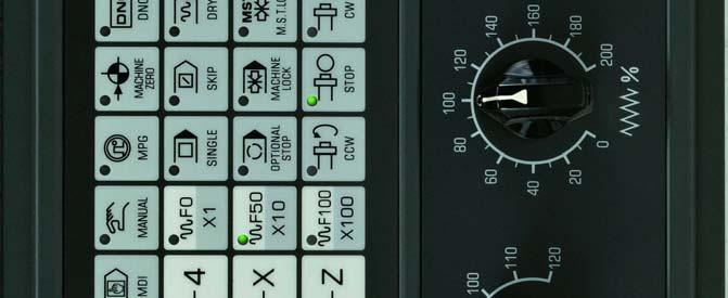
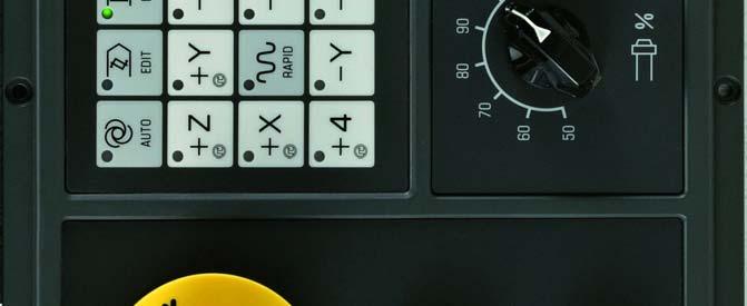

209 Chapter Four Operation Part 2 Operation 197
 is cut off after this button is pressed.")
210 4.3.2 Emergency Stop (red) GSK983Ma Milling Machine Center CNC System User Manual In the emergencies, movements of all machine axes are stopped immediately by pressing Emergency Stop button. At the same time, the button is locked in the stop position. The button is released by turning it CW or CCW. Note 1:Excitation signal (machine power) is cut off after this button is pressed. Note 2:NC unit is on a status of reset. Note 3:Make sure all troubles are removed prior to releasing the button. Part 2 Operation code. Note 4: After this button is released, return to reference point with manual operations or G Mode Selection Mode display field 198
211 Chapter Four Operation Mode Functions Auto (MEMORY) mode (1)Programs in the memory can be performed (2)The sequence number of programs in the memory can be searched Used for the following operations: (1)Save program in the memory (2)Program alteration, insertion and deletion Edit mode(edit) (3)Output programs from the memory and edit other programs MDI mode(mdi) Manual mode(jog) Data can be input manually by MDI and machine operation panel. Execute jog feed and rapid traverse. Part 2 Operation Handle feed MPG(HANDLE) Reference return Reference (REF) return Execute parts machining programs which are sent from USB interface to DNC storage area DNC mode 199
 Select MANUAL mode. 2) When rapid move function is invalid, select move axis, and the machine moves along the seleted direction.")
212 4.3.4 Operations Related to Manual Operation GSK983Ma Milling Machine Center CNC System User Manual In addition to operating automatically by program, the switch can be used for the following manual operations Jog Feed Machine can be operated by jog feed. 1) Select MANUAL mode. 2) When rapid move function is invalid, select move axis, and the machine moves along the seleted direction. Part 2 Operation Note 1: Two axes can be controlled simultaneously by manual operation. Note 2: After power on, the selected axis will not move immediately even the mode selection is set to MANUAL position. Now it is necessary to reselect an axis. 3)Select jog federate Feedrate Switch position Lead screw for feed in metric unit Lead screw for feed in inch unit mm/min inch/min inch/min mm/min 0% % % % % % % % % % % % % % % % % %
213 Chapter Four Operation 180% % % % % % % Note 1: Values listed in the table vary with different machines. Note 2: Error of the federate listed in the above table is approximately ± 3%. 4)Rapid traverse 1) Select Manual mode 2) Press Rapidkey to make rapid function valid 3) Select one of rapid override from F0 F25% F50% and F100% (Standard panel has selections of F0 F50% and F100%) 4) Select move axis, the machine moves along the seleted direction. Note 1: The federate, time constant and acceleration/deceleration mode for manual rapid traverse are the same as the rapid traverse commanded by G00. F0 feedrate is set by NC parameter 113 of the system. F25% F50% F100% and rapid federate are in proportion. Note 2: When the machine has a storage-type travel limit selecting function, the axis with the function of reference point return can be set by the system parameter 10 BIT 0. If the RAPID key is pressed after power on or emergency stop but before reference point return function is performed, the feedrate will not change into rapid feed but maintain at a Jog feedrate. This is because storage-type travel limit does not take effect before the manual reference point return, thereby preventing the machine from quickly reaching the end of travel. Part 2 Operation Handle Feed (MPG) Accurate adjustment for the rate of the machine feed can be done with a manual pulse generator (1) Select MPG mode (2) Select move axis (3) Turn the handwheel of the MPG CW + direction CCW - direction (Direction varies with different specifications of machine tool manufacturers) (4) Amount of movement: the following selection switches are fixed on the panel or handheld 201
214 GSK983Ma Milling Machine Center CNC System User Manual unit. 1 indicates that movement amount is multiplied by 1; while 10 indicates that movement amount is multiplied by 10; 100 indicates that movement amount is multiplied by 100. MOVEMENT AMOUNT OF EACH SCALE Input system Metric unit 0.001mm 0.01mm 0.1mm Inch unit inch 0.001inch 0.01inch Note 1: If the MPG rotates at a speed over 5 revs per second, rotation amount of MPG will differ from the move distance of the machine. Therefore, do not rotate the MPG too fast. Note 2: When override 100 is selected and the MPG is turned quickly to make the tools or work table move at rapid traverse rate, the machine will be subject to impact if it is stopped abruptly. The selection automatic acceleration/deceleration function is also active for JOG feed. Therefore, it may reduce mechanical shock Manual Absolute Value Part 2 Operation For manual absolute value setting, please refer to Menu switch function. When the switch is ON, move amount of manual operation is added to coordinate axis. (1) When manual absolute switch is ON, coordinates vary with the manual operation. (2) When manual absolute switch is OFF, coordinates do not change. (Example) There is a program block as follows: G01 G90 X100.0 Y100.0 F100;1 X200.0 Y150.0 ;2 202
215 X300.0 Y200.0 ;3 Chapter Four Operation a) When the above block 1 has been performed, block 2 is performed after manual operation (Move 20.0 in X direction, move in Y direction) b) Press FEED HOLD key during the execution of the block 2. After manual operation (Y+75.0) is performed, press CYCLE START key to release hold mode and continue the execution. c) Press FEED HOLD key during the execution of the block 2. It resets after manual operation (Y+75.0) is performed. Execute block 2 again. Part 2 Operation d) When manual operation is followed by a single axis command, only the specified axis returns to its programmed absolute position. N1 G01 G90 X100.0 Y100.0 F5000; N2 X200.0; N3 Y160.0; 203
216 GSK983Ma Milling Machine Center CNC System User Manual Part 2 Operation e) When manual operation is followed by an incremental command, the position that the tool moves to is the same with that is commanded while manual absolute switch is set to OFF. Note: When tool radius compensation C offset is enabled, insert manual operation. The actual move path of the tool is as follows: (1) Manual absolute switch is OFF When tool radius compensation C is enabled, if Manual Absolute switch is turned off for manual operation. After restart, the tool will move horizontally by the inserted move amount of manual operation. (2) Manual absolute switch is ON If Manual Absolute switch is set to ON for manual operation in the tool radius compensation C mode. The automatic running path of the tool by absolute command after reset is as follows: The tool path for the blocks after manual operation runs parallel to the vectors of the origin of the next block. Tool path is determined by the vectors between the next two blocks. In corner machining with intervention of manual operation, the tool path calculation is identical with the above. If the program is composed of incremental commands rather than absolute commands, tool path is identical with that when the Manual Absolute switch is set to OFF. (a) Perform manual operation in block execution Example 1 In the programming path (PA PB PC PD)of the following figure, the tool is moved the point PH between PA and PB to the point PH by manual operation provided Feed 204
217 Chapter Four Operation Hold key is pressed. The end point PB of the current block transfers to point PB due to the offset as a result of manual operation and the vectors VB1 and VB2 of the original point PB also trasfer to VB1 and VB2 Part 2 Operation It s not required to compensate the vector between the next two blocks (tool path from PB to PC and the path from PC to PD). New vector with compensation (VC1 VC2 )is generated from mutual relationship between the two blocks (tool path from PB and PC to PD, and the path from PC to PD). However, the vector VB2 is identical with vector VB2, the offset can not be correctly executed on the tool path between PB and PC. However, for the blocks after point PC, tool offset can be executed precisely. Sample 2 If manual operation is inserted in corner machining in case of tool radius compensation, the tool path after manual operation will be determined by the same method as Example 1. Vectors VA2,VB1 and VB2 in the following figure are gotten by transferring the vectors VA2,VB1 and VB2 separately by a jog move amount. New vectors result from vectors V C1 and V C2. Blocks after point PC will be precisely executed by tool radius compensation. 205
218 GSK983Ma Milling Machine Center CNC System User Manual Part 2 Operation (b)if manual operation is inserted after the execution of a block, the vectors VB1 and VB2 for the end points of the current block will be moved in parallel, and the method for determining the following path is the same with (a). MDI operation can be inserted after a block is executed by a single block function. The tool path after MDI operation is the same with that after the insertion of a manual operation. 206
219 Chapter Four Operation Manual Reference Point Return (reference position) Manual operation may be used for zero return: 1)Select Machine Zero mode. 2)Select zero return direction for each axis to make it move towards the reference point. The machine rapidly moves to the deceleration point and then move towards to the reference point at speed FL (parameter Number 114). Rapid traverse override is still valid in rapid move. 3)Machine stops at reference point and reference return indicator lights up. Note 1: Indicator lights up after return to reference point. If it still in machine zero return mode, the machine can not be operated by jog mode. Note 2: Turn off the reference return indicator by the following operatios:(1)move away from the reference point(2)press Emergency Stop button. Note 3: For the distance to the reference point, please refer to the manual supplied by the machine manufacturer. Part 2 Operation Related Operations in Automatic Running The machine can operate automatically by programs Start Automatic Running Steps for starting and running programs stored in memory: (a) Select program Number. Refer to Program Number Retrieval. (b) Select automatic operation. (c) Press Cycle Start key to sart automatic running. At the same time, Cycle Start indicator lights up. 207
 (b) (c) Feed Hold key is pressed.")
 (d) Mode Selection switch is set to a wrong position (excpt AUTO, DNC, EDIT and MDI mode) (e) When sequence Number is being")
220 GSK983Ma Milling Machine Center CNC System User Manual Note 1: Press Cycle Start key in Edit mode. Programs read in are stored. The way of storing is the same with that of press INPUT key in parameter setting. Note 2: Cycle Start key is invalid in the following conditions: (a) (b) (c) Feed Hold key is pressed. Emergency Stop key is pressed. Reset signal is enabled (Contact machine tool manufacturer for dedails) (d) Mode Selection switch is set to a wrong position (excpt AUTO, DNC, EDIT and MDI mode) (e) When sequence Number is being retrieved. (f) When an alarm is being given. (g) Automatic running is selected. (h) When NC system is unprepared (NO READY) Stop Automatic Running Part 2 Operation Press Feed Hold key. Press Feed Hold key, and feed hold indicator lights up, cycle start indicator goes out. (a) If the tool is running, feed decelerates to stop. (b) If the machine is in Stop state, it will not continue in this state, and the same as Feed Hold state. (c) The machine stops after M, S, T or B functions are executed Auto Mode Storage area capacity of executed program in AUTO mode In AUTO mode, storage area capacity of executed program is 256K bytes. For available space, switch the page to program check page or program page in Edit mode, press Cancel key first, is displayed on character column, then press Shift key, the system will switch to program list page automatically, available space of storage area is displayed on the character column Transmit the machining program to the memory by USB in the Auto mode The related parameter with the function of the USB transmit program 208 When USB interface is used for transmission, set parameter of USB interface first, related
Press key on NC unit,and related pages are displayed on LCD; Part 2 Operation 2)Press expanded key on the small")
221 Chapter Four Operation parameters are NC parameter N0340 and N0341.If USB interface is used as a input or output unit, set N0340 and N0341 to 0 separately Transmit machining program from U disk to the memory by USB interface Steps:1)Press key on NC unit,and related pages are displayed on LCD; Part 2 Operation 2)Press expanded key on the small keyboard, and U disk operation, DNC storage area, DNC program page selection can be displayed; 209
222 GSK983Ma Milling Machine Center CNC System User Manual 3)Press key on the small keyboard, operation options are displayed. The contents of the option can be selected by moving yellow cursor by UP/DOWN key. Part 2 Operation 4)When the yellow cursor is moved to Copy program (UsbDisk->NcRam in edit mode, press key to display file list of the machining program on U disk. 5) Machining program needed can be selected by moving blue cursor with UP/DOWN key. Press key on the small keyboard to transmit the machining program to the memory. It will prompt: copy completion after machining program duplication is finished. Program Number on the upper right and program sequence Number are changed. If Copy key is pressed in non-edit mode, it will prompt: operation is valid only in edit mode. 210
223 Chapter Four Operation Copy key is used to load data; Refresh key is used to refresh contents on the screen. Usually, screen refresh is needed to update the contents when plug in or pull out U disk. Return key. Generally, there is no return key in the system for user to return the list of higher level on expanded menu Output machining program from program memory to U disk by USB interface Take USB interface as output unit, set parameter N0341 to 0; Steps:1)The same as the way of program input, switch the page to U disk operation page, and enter U disk operation items; Part 2 Operation 2)When the yellow cusor is moved to the position Copy PRO. (NcRam->UsbDisk) in edit mode, press key to display file list of machining program in U disk. In Edit mode, key in program Number to be input, for example: program O0002, that is, key in 2, and then press key, program O0002 is input to U disk. 211
224 GSK983Ma Milling Machine Center CNC System User Manual Press key directly in Edit mode to copy all programs to U disk, and the file name is 983 Pro.txt. Part 2 Operation If there is a file with a same name is in the U disk, the system will add a sequence Number with brackets behind the file name, for example: 983 Pro(1).txt is used to distinguish from the one with the same file name. When file number exceed screen display scope, the cursor key is used to display contents of the next page by moving blue cursor. key is used to copy a specified program to U disk; key to copy all machining program to U disk; 212
225 Chapter Four Operation DNC Running Capacity of DNC storage area and related parameter of USB interface In DNC running mode, input program to DNC storage area by USB interface, select program to be machined in DNC storage area to process. Capacity of DNC storage area is 160k bytes. For DNC function, first set parameter of USB interface, related parameters are NC parameters N0340 and N0341. If take USB interface as input and output unit, N0340 and N0341 should be set to 0 separately Transmit processing program to DNC storage area by USB interface Steps:1)Press key on NC unit,and related pages are displayed on LCD; Part 2 Operation 2)U disk operation, DNC storage area and page selection of DNC program can be displayed by pressing expanded key on small keypad; 213

 After yellow cursor is moved to Copy PRO. (Usb Disk->DNC Vol.")
226 GSK983Ma Milling Machine Center CNC System User Manual 3)Operation options are displayed by pressing key on the small keypad. Contents on the option can be selected by moving yellow cursor with UP/ DOWN cursor. Part 2 Operation 4) After yellow cursor is moved to Copy PRO. (Usb Disk->DNC Vol.) in DNC mode, press key to display file list of the processing program in U disk. 214
227 Chapter Four Operation 5)Select needed program by moving blue cursor with UP/DOWN cursor. Transmit machining program to DNC storage area by pressing key on the small keypad. There is a progress prompt during transmission. After duplication is finished, it enters machining program of DNC storage area automatically for further program selection. Part 2 Operation Cancel key is used to delete duplication course of loading Select processing program in DNC storage area to perform DNC machining In order to meet the requirement for securely execute high capacity programs, the GSK983Ma system adopts 160M DNC memory area to store the programs to be machined. Many processing programs can be stored in DNC memory area to meet the requirements of different machining. Therefore, it is necessary for user to select machining program before machining. Steps:1)Enter processing list of DNC storage area, and slect machining program by moving blue cursor with UP/SOWN key; 215
When key is pressed, the processing program where the blue cursor locates is selected as the program for DNC machining, and the DNC program screen is entered automatically.")

228 GSK983Ma Milling Machine Center CNC System User Manual key is used to delete programs in DNCstorage area; key is used to confirm the machining program selected by the blue cursor; Part 2 Operation 2)When key is pressed, the processing program where the blue cursor locates is selected as the program for DNC machining, and the DNC program screen is entered automatically. Press YES key in DNC mode to select the program for DNC machining. Three-dimensional effect of the YES key varies, which indicates the processing program is in a confirmation state. Processing program can be performed by pressing Cycle Start key continuously. Press Reset key to cancel the confirmation state of the machining program. Then press YES key again to operate the program again. The machining program is set to the confirmation state of the DNC machining, and the program cursor is moved to the head of the program. DNC machining state is confirmed 216
229 Chapter Four Operation Single Block When SINGLE is valid, the control unit executes only a block each time when the Cycle Start key is pressed. When the SINGLE BLOCK is set to 1 in the page of the menu switch setting, the control equipment is stopped after performing one program. Press cycle start key, and control unit stops after the next block is executed. Note 1: In G28, G29 or G30 mode, tool will stop at intermediate point if single block function is used. Note 2: In canned cycle machining, if single block function is valid, the tool will stop on the cycle path 1, 2 or 6 of canned cycle (see the following figure). When the repeated calculation of canned cycle is not 1, execution stops each time except for the 6 block of final cycle, and Feed Hold indicator lights up. Feed Hold indicator lights up each time for the 1 and the 2 blocks stop. Note 3: For blocks M98P,M99,and G65,G66 or G67, single block stop is invalid. However, if commands in block M98 or M99 are the address except O, N, L and P, single block stop is valid. Part 2 Operation Restart after Feed Hold or Stop (1) Select Auto mode. (2) Feed Hold indicator goes out when cycle start key is pressed Manual Operation in Automatic Running (1) In automatic running, running stops by pressing feed hold key on the panel or making single block function valid (2) Record coordinates of the stop position displayed by the position display unit. (3) Perform manual operation (see ) (4) Return tool to recorded coordinates (start point of manual operation) (5) Restore to the previous state and mode before manual operation to restart automatic running. (6) Press cycle start key. 217
 Make single block function valid, when current block is executed, feed axis stops to wait the next")
230 MDI Operation in Automatic Running GSK983Ma Milling Machine Center CNC System User Manual (1) Make single block function valid, when current block is executed, feed axis stops to wait the next command. (2) Select MDI mode. (3) Input required command, commands in MDI mode can be executed by pressing Cycle Start key. (4) After commands in MDI mode are executed, restore modal parameter and state before MDI opertation. Select AUTO mode again, press cycle start key on operation panel to continue program execution. Note 1:The modal data reserved in cycle movement is influenced in the execution of MDI command. Note 2: The modal data commanded by MDI will be active for the automatic operation. Note 3: Tool nose radius compensation is unallowed during MDI operation. Note 4: MDI operation is unallowed in feed hold state Skip Over a Block Part 2 Operation WhenSKIPor menu switch BLOCK SKIP 1~9 in setting is ON, and some block contains /n (n=1~9), control unit is allowded to skip this block. Each number from 1 to 9 is correspond to a switch. Note 1: When block is read in buffer, it decides the validity of arbitrary block skip function. Therefore, this function is invalid to blocks that have been read in buffer register. Note 2: Skipkey on the operation panel can make only one number in the scale 1-9 is slipped by an arbitrary block. Machine tool manufacturer determines the one controlled Feedrate Override For the federate set by the F function, the override with 10% increment in the corresponding scale 0~200% can be set. Actual federate can be displayed on the command page of the current block. 218
231 Chapter Four Operation Dry Run If Dry or Dry Run in menu switch of Setting is set to ON during the operation of the memory or MDI instruction, the F function is not active and the tool will move as the following speed. Part 2 Operation Rapid traverse key ON/OFF Rapid traverse Cutting feed Rapid traverse key ON Rapid traverse Max. jog feedrate Rapid traverse key OFF Jog federate (see the note ) Jog feedrate Note: Dry run of rapid traverse can set to be valid or set to be invalid by parameter 7 BIT 0 (RDRN) Machione Lock When Machine Lock or menu switch of Setting Machine Lock is set to ON, the pulse of move command is restrained. Therefore, the position of feed cycle start or manual operation is updated as input command, but the carriage is not move and the machine coordinates are not changed. This function is used for checking programs. Note 1: When G27, G28 or G30 command is set, the machine will not return to the reference point. Hence, the indicator for returning to the reference point is not light up. Note 2: The M.S.T and B functions are executed. Note 3: The NC parameter 26 BIT 0 decides whether the machine lock is active airing the 219

232 GSK983Ma Milling Machine Center CNC System User Manual automatic running M.S.T. Lock Key M.S.T lock or M.S.T lock of menu switch in Setting is ON, M. S. T. and B function is locked, G function still executes, and this function is also used to program checking Display Lock Part 2 Operation When menu switch Display Lock in Setting is set to ON, relative coordinates displayed in position display unit are locked. For example: when the coordinate system is moved by manual operation, adopts this switch to avoid the displayed value is changed by manual move amount Mirror Image In automatic running, when the mirror image switch of X, Y and 4 th axis is connected, axes will rotate reversely. In manual reference return and automatic reference return, the movement between intermediate point and reference point is not move in reverse direction, position display depends on tool actual motion. This function can be achieved by setting parameter with MDI unit (see section 4.4.7) 220
233 Rapid Traverse Override Chapter Four Operation Any rapid traverse switch with override 100% 50% and F0 can be set on the panel. When rapid rate is 10m/min, and the override is set to position 50%, actual feed speed is changed to 5m/min. F0 is a fixed speed provided by machine tool manufacturer (NC parameter is No. 113). The function applies to the following conditions: (1) The rapid traverse specified by G00; (2) The rapid traverse in canned cycle; (3) The rapid traverse rate in G27,G28,G29 and G30 modes; (4) Jog rapid traverse rate; (5) The rapid rate for manually returning to the reference point Retrieval Function of External Workpiece Number Select the Number of workpiece to be machined by the switch fixed on panel (There is no example of panel in this manual). ( Processing programs have been stored in storage beforehand) press start key, the system will perform programs correspond to work piece number. By using this function, users do not need to seach saved program number, operation waiting time and operation errors are reduced. (1) Program preparation: In the conditions of using this function, specified program number should correspond to number of work piece to be machined. That is, select a number from 01~31 for each piece to be machined. Corresponding program number is as follows: Part 2 Operation 0(:) 0 0 ( 0 is EIA, :is ISO) Workpiece number(01~31) Any workpiece number Store them to the part program memory. See the following figure: each program should begin with the address 0 that followed by program number and end with M02,M30 or M99. The programs that are not relervant to piece number are allowed to store. 221
234 GSK983Ma Milling Machine Center CNC System User Manual ; N 0001 G00 ; Programs correspond to workpiece 01 N 120 M02; ; N 0001 G00 ; Programs correspond to workpiece 02 N 300 M30; ; N 001 G00 Programs correspond to workpiece 04 N 080 M02; ; N 001 G00 N 034 M99; programs are not relervant to workpiece number Part 2 Operation 222 Note 1: Each program should begin with the letter 0 that followed by program number and end with M02,M30 or M99. M02,M30 and M99 can not be specified in the middle of the program. If one is specified in the middle, the following programs will be seen as other block (When the programs are being saved in storage, the sequence number of blocks behind M02,M30 or M99 will be seen as program number immediately) Note 2: Allowded quantity of workpiece number is determined by machine tool manufacturer (Please refer to machine tool manufacturer s manual) Note 3: When machine system has external part number retrieval function A, allowded max. part number is 31. The rogram number corresponds to the part number should bagin with digits 00. (2)Operation methods Operation methods are different with different machine tool manufacturers. Operation methods introduced here are general ones. Detailed operations must be done with user manual provided by machine tool manufacturer. Note 1: Select Auto mode, and then set corresponding program (01~31)of workpiece number by the rotational switch fixed on operation board of the machine. Press the START key, and corresponding program of specified workpiece number is retrived, process is done from the program. Note 2: Set workpiece number to 00, and press START key, corresponding program will not be retrived. But start from the executable part of the current program. When it starts from the middle of the program or executed program irrelevant to workpiece
235 Chapter Four Operation number, once sequence number or program number is retrived, set workpiece number to 00 and press START key again. Note 3:This function is not used for MDI running, but only for Automatic running. Note 4: If corresponding program number for workpiece number is not stored in memory, alarm (NO.59)will occurs by pressing START key. Note 5: Even the workpiece number is selected by indexing plate, it not always necessary to select corresponding program. Please refer to machine tool manufacturer s manual for corresponding program operation. When workpiece number function is selected, NC system retrives program in the Reset mode after automatic running is started MPG (manual pulse generator) Interruption For specified axis in automatic running (defined by parameter, corresponding NC parameter is no. 314). Except automatic running of the axis itself, movements that operated by MPG can be executed MPG Interruption Manual interruption can be performed by turning the manual pulse generator in the following conditions. (1) Mode: Auto mode or MDI mode. (2) Operating state: Manual insertion is possible during auto running and linear interpolation, arc interpolation. However, the following conditions are excluded: (Ⅰ)When an alarm is being given; (Ⅱ)No axis is moving; (Ⅲ)When positioning is valid; (Ⅳ)When interlocking is valid; (Ⅴ)No move command. (3) Handle axis selection signal Manual axis selection signals (HX HY HZ H4 H5) are powered up (contacts making) for the axis to perform manual insertion. Part 2 Operation Movement of Manual Insertion (1) Amount of movement: The amount of move by manual insertion is identical with that of the MPG feed. The amount of move depends on the scale of the manual pulse generator and manual feed overrides (X1, X10 and X100) and is added to that of automatic running. Move speed: The axial speed for manual insertion is the result of the addition of the move speed of auto running to that by manual insertion. Therefore, axial speed will be limited to rapid traverse rate (when NC parameter #306.6 CHR=1) in the event that axial speed exceeds rapid traverse rate. Because the part that exceeds the rapid traverse rate is lost, the amount of move is not consistent with the value displayed on the indexing plate. (3) The relations of manual insertion to various signals are as the following table: 223
236 GSK983Ma Milling Machine Center CNC System User Manual Signal Machine locked Displayed locked Mirror image of X axis Movement It is affected, that is, the tool does not move if the machine is set to ON It is affected, that is, the relative coordinate does not change if the display is locked It is not affected, that is, machine moves positively if hand disk is rotated in positive direction (4)The relations of manual interruption to various signals are as following table: Part 2 Operation Display Absolute coordinates Relative coordinates Machine coordinates Movement Not affected: Manual-inserted pulse is not added to absolute coordinates Affected: Manual-inserted pulse is added Affected: Manual-inserted pulse is added (5)Display of move amount: Move amount by manual insertion may be displayed by(dgnos no. 805~809)key. When DGNOS is displayed, press function key in DGNOS MDI. Diagonosis data Number Manual-inserted move amount of Axis X Manual-inserted move amount of Axis Y Manual-inserted move amount of AxisZ Manual-inserted move amount of the 4 th axis Manual-inserted move amount of the 5 th axis Unit: 0.001mm (metric system) inch(inch system) Note: When clearing valid is set in reset signal (NC parameter #7.3 is 1), The move amounts may be cleared by pressing reset key Manual Spindle Function 224 Spindle rotates positively: Press CCW in manual mode, spindle rotates CCW. Spindle stops: Press STOP in manual mode, spindle decelerates to stop. Spindle rotates reversely: Press CW in manual mode, spindle rotates CW. Note:Actual rotational direction of spindle is different for various machines, please


237 Chapter Four Operation refer to machine tool builder s manual. Spindle orientation:when the machine is matched with servo spindle driver, the system will send orientation start signal to servo driver by pressing ORIENTATION key in Manual mode or Auto mode, MDI command M19. After spindle orientation is performed in the driver, completion signal is sent to CNC, and the spindle orientation is finished. This function is mainly used for tool shifting and hole boring. Spindle speed override: Spindle speed override can be adjusted from 50% to 120% by this switch. When the machine tool has spindle encoder function, the system will display spindle speed. The value of spindle speed can be displayed in current block command. Part 2 Operation 225


238 GSK983Ma Milling Machine Center CNC System User Manual Manual Auxiliary Function The functions of the key and execution logic are determined by PLC programming, please refer to PLC user manual of corresponding version. They control ON/OFF of machine parts separately. Usually, press ON and then press OFF. The function of USER1~USER10 keys are not difined, which can be dified by user s requirement. Part 2 Operation Tool case vertical, tool magazine debugging, tool case horizontal, and mechanical arm rotation: This series of function is used in tool magazine debugging. Please refer to corresponding PLC manual for details. LED displays curren tool number. 4.4 Display and Operation of the NC Unit with LCD Character Displayer The NC unit is usually installed front upper part of the control cabinet. It is consists of LCD displayer and keys as shown in the following figure. Note: Different installation and different NC unit are provided for the 983M system. Only a typical one is listed in this manual. 226


239 Chapter Four Operation Part 2 Operation 227
240 GSK983Ma Milling Machine Center CNC System User Manual Functional keys: Different screens are selected and displayed by functional keys. The names and contents of each functional key are listed bellow. Press once Display the current position Press once Press twice Press three times Press once Press twice Set the display and setting of data Display and setting of user macro varibles Display and setting of menu switch Display the program detection Display program contents (see ) Part 2 Operation Press three times Press once Press twice Press once Press twice Press once Press twice Press once Press twice Press once Press twice Display program contents in EDIT mode The program being executed or executed and the following programs are displayed in the mode other than EDIT mode. Display and setting of the NC parameter Display and setting of the PLC parameter Display and setting of the offset value Display and setting of the offset of workpiece origin of working coordinates Display the NC alarm contents Display external message Display command value and the command input by MDI panel Display the message of program restart Display the system diagnosis data Display the message of tool life management 228


241 Chapter Four Operation Introduction for other keys on MDI keypad Reset key For CNC reset and alarm eliminating, etc. Input key Cancel key When address key or numerical key is pressed, input data is displayed on screen but it still in buffer. Press input key, and these data are saved in register. Delete characters in buffer from the end by pressing cancel key. Edit key Alteration, insertion and deletion can be done by pressing these three keys in keying in data. Shift Some address keys include two kinds of characters, which are selected by pressing shift key. Input characters in the lower right corner when sign ^ is displayed on the screen. Address key Part 2 Operation Input letters by pressing address key. 229
:Turn Part 2 Operation display screen forward or backward for one page. Cursor moving up or down.")
242 GSK983Ma Milling Machine Center CNC System User Manual Numerical key and character key Digits and punctuation can be input by pressing numerical key. Key in ; by EOB key. Page turning up and down(page Up/Down):Turn Part 2 Operation display screen forward or backward for one page. Cursor moving up or down. Soft keys:its function is defined by the contents in the lower part of the display screen. Extend key Return key State Display 230 The status indication of the system is displayed on the lower part of the screen: (1)Editing type display

Edit")
The")
The")

Stop drawing")
243 Chapter Four Operation (2)Alarm state display (3)Edit searching display (4)The system restart display (5)The background program is in editing Part 2 Operation (6)Stop drawing (7)It is in drawing 231

244 GSK983Ma Milling Machine Center CNC System User Manual (8)Continuous drafting or single block selection Part 2 Operation The symbols displayed are as follows: NOT READY: It indicates that the control or servo system fails to operate. LSK: It indicates the symbol is skipped when data is input. BUF: It indicates that a block is read in but not executed. The blocks not executed still exist after reset in modes other than MDI. ABS:It indicates that MDI commands are absolute commands. Press SHIFT key to enter the INC state. INC:It indicates that MDI commands are incremental commands, Press SHIFT key to enter the ABS state. SRCH: It indicates that sequence Number retrieving function is working (this symbol is blinking). RSTR: It indicates that the period from the program restart to the completion of returning to the last axis (this symbol is blinking) Alarm: It indicates that alarm is being given. Press ALARM key to display the alarm form (this symbol is blinking) Editing: It indicates that edit function is working. Blinking indicates that the program is being transmitted. The operation of edit stopping must be done when the symbol exists. The program is edited in the background: The function of background edit is used. It is drafting: The path is being drafted when the system is running. Stop drawing: The function of drawing is stopped. Drawing stopped/in drawing continuous blocks/single block: Directly drawing function is used. The path can be drafted without running program. 18:55:57 :time display Key Input The contents input by address key or numerical keys are displayed at the lower part of the screen 232 When the screen is displayed by pressing the POSITION or ALARM of the function keys,
245 Chapter Four Operation data can not be input. Press D/H once to input D, and press again to input H. Only a word consisting of one address and a figure can be keyed in when program edit is not being performed. Pressing CANCEL to clear one word. In program editing, one or more words can be input, and a block or a string up to 32 characters can be entered. The last entered characters can be cleared by pressing the CANCEL key. If the CANCEL key is pressed continuously, the typed characters will be cleared in succession. Note: In Edit mode, program edit is enabled when the PROGRAM key is pressed Display of Program Number and Sequence Numbers Program number and sequence numbers are displayed at the top of the screen as shown in the following figure. Part 2 Operation Definition of the program number and sequence number are displayed as the following table: Mode Operation Contents The modes Operations other than the Display the last executed sequence other than following ones number Editing Sequence number retrieving Display the sequence number The functional key is in (MENORY) Return the head of the block PROGRAM state. Auto mode Display this block Press cursor key. (EDIT) Edit mode (MEMORY) Auto mode The functional key is in PROGRAM state. Press cursor key. The functional key is in PROGRAM state. Press cursor key. Press RESET to enter reset state Program number retrieving Visit programs along the + direction from the position of the current memory Visit programs along the direction Display the first N value Return to the head of the program. Display this block Display retrieved sequence number 233
246 4.4.4 Alarm Display (functional key ALARM ) GSK983Ma Milling Machine Center CNC System User Manual When ALARM is indicated at right bottom of the screen in case of alarm occurs, warning messages may be visited by the following procedures: Press the ALARM key, when the information about operation is displayed, press the ALARM key again to display alarm message. Refer to Appendix 6 for the significance of the alarm number. Part 2 Operation Note:Once alarm occurs, alarm contents will display on screen automatically Operation Information (the content of external alarm message) Once the machine sends out operation message, the message will be automatically displayed on the screen. 234
247 Chapter Four Operation If operation information is needed to display after some other page is selected, press the ALARM key. When alarm message is displayed, press the ALARM key again Current Position Display and Reset (functional key POSITION ) (1) Press Position key. (2) Press the PAGE key. Data is displayed in one of the following three modes. (Ⅰ)Position displays in a relative coordinate system. Operator can clear the relative coordinates. Clearing: Press X Y or Z, the address characters pressed will continuously blink. Press SHIFT key again, the relative position of the blinking address will be cleared. Note: Reset can only be done in the state of automatic running stops. (Ⅱ)Position displays in a absolute coordinate system Part 2 Operation (Ⅲ)Display of the ALL position Display the current position by the following coordinates simultaneously. (a) (RELATIVE)Relative coordinate system (b) (ABSOLUTE)Absolute coordinate system 235

It displays the command value that is originally set.")
248 GSK983Ma Milling Machine Center CNC System User Manual (c) (MACHINE)Machine coordinate system (d) (DISTANCE TO GO)Distance to go Part 2 Operation DISTANCE TO GO indicates the remaining move amount of a block. The position of each coordinate system cannot be cleared in the ALL position interface. The unit of machine coordinate system is the same as that of machine system Display of Command Value (functional key COMMAND ) (1) Press the COMMAND key. (2) Press the PAGE key. The page is displayed by the following three modes: (Ⅰ)It displays the command value that is originally set. As shown in the above figure, digits follows character F % indicates the federate of program federate multiply by feed override. SACT: SACT and the following digits indicate actual speed of the spindle. 236
249 Chapter Four Operation (Ⅱ)It displays the command value input by MDI or the command value to be executed next time. (Ⅲ)It displays the command value of the next block to be executed during the tool nose radius compensation C. Part 2 Operation Setting (functional key SETTING ) Display and Setting of Input, Output, etc. (1) Press the SETTING key; (2) Press the PAGE key. Setting and display have the following two modes. (Ⅰ)Setting and display of input and output. 237
 Set the mode selection to MDI mode. (b) Press the cursor key to move the cursor to the item to be altered. The cursor cannot be moved with the address key N.")
250 GSK983Ma Milling Machine Center CNC System User Manual Part 2 Operation Setting (valid when the program lock is ON, invalid when it is locked, whose state can be switched by parameter 11 BIT5 DECI) (a) Set the mode selection to MDI mode. (b) Press the cursor key to move the cursor to the item to be altered. The cursor cannot be moved with the address key N. (c) Enter 1 or 0 by pressing the P key as shown in the following table. 0 1 X mirror image mirror image OFF mirror image ON (X MIRRORIMAGE) Y mirror image mirror image OFF mirror image ON (Y MIRRORIMAGE) Mirror image of the 4 th axis mirror image OFF mirror image ON (4 THMAXISMIRRORIMAGE) TV check NO YES (TV CHECK) (PUNCH.CODE) EIA ISO (INPUT UNIT) mm inch (INPUT DEVICE1) DNC (set to 0) (INPUT DEVICE2) unused RS232C input In operation, press P, O or 1,INPUT key in sequence. Note 1: Unselected function cannot be set. For example: (INPUT UNIT)=1 cannot be used for a metric-system machine when metric-system switch selection function is not available. Output code(punch CODE)=1 cannot be set when ISO code input selection function is not available. Note 2: INPUT CODE is automatically rewritten when G20 (in inch system) and G21 (in metric system) code is executed. Note 3: When data is being input, code standard specifies ISO or EIA is irrelevant to input. ISO or EIA code can be identified automatically. Note 4: Output device for data output is set by No
 059 Running time (Unit: s) (TMSEC) 067 Canned cycle G73(high-speed peck drilling cycle), set retraction amount (CYCR) 068 Canned cycle G83(deep-hole drill cycle), rapid feed is changed to")
251 (Ⅱ)Other settings and display Chapter Four Operation The displayed numbers and their meanings are as follows; Data number Meaning 057 Running time (Unit: hr) (TMHOR) 058 Running time (Unit: min) (TMMIN) 059 Running time (Unit: s) (TMSEC) 067 Canned cycle G73(high-speed peck drilling cycle), set retraction amount (CYCR) 068 Canned cycle G83(deep-hole drill cycle), rapid feed is changed to specified distance (CYCD)of cutting federate. 141 Running time (TIME1) 151 X value of acme 1 of storage travel limit 2 (LT2X1) 152 Y value of acme 1 of storage travel limit 2(LT2Y1) 153 Z value of acme 1 of storage travel limit 2 (LT2Z1) 155 X value of acme 1 of storage travel limit 2 (LT2X2) 156 Y value of acme 1 of storage travel limit 2 (LT2X2) 157 Z value of acme 1 of storage travel limit 2 (LT2X2) 180 Set sequence number for corresponding stop 319 Settings (PRG8.MSBL) 340 Select input device (IDVICE) 341 Select output device (ODVICE) 355 Automatically adjusted decelerate distance of the end point of the inner corner (AOVEL) 356 Automatically adjusted accelerate distance of the end point of the inner corner (AOVLS) 407 Scaling Note 1: Data in the above table can be took as data of corresponding parameter setting. Note 2: The same data numbers in the above table should be set as the way of corresponding parameter number. Note 3: Please refer to appendix 5 (parameter) for details. Note 4: The detailed contents of data number 340 and 341 are as follows. Part 2 Operation I DVICE O DVICE 239
252 GSK983Ma Milling Machine Center CNC System User Manual I DVICE select the input device storing data to the memory. When the set input device is (INPUT DEVICE)2=1, this setting is valid. O DVICE select the output device that is used for data outputting or set by parameter. Setting Input / output device 0 USB interface 2 RS232 interface is used for input and output. Set baud rate and other parameter to 311. Setting (valid when the program lock is ON, invalid when it is locked,whose state can be switched by parameter 11 BIT5 DECI) (a) Select MDI mode. (b) Press the cursor key to move the cursor to the item to be altered. The cursor cannot be move with the address key N. (c) During operation, press P Numerical key and INPUTkey in succession Display and Setting of User Macro Program Variables Part 2 Operation It is possible to display all common variable values and local variable values of currently called user macro program body on LCD. When a variable value is <null>, the display will be blank. When an absolute value is over , it displays OVER FLOW. When an absolute value is not zero, but less than , it displays UNDR FLOW. (1)Select MACRO of the page SET. Press SETTING key to enter SETTING DISPLAY page. Press it again to enter MACRO page. (2)Because the display concludes six pages, it is necessary to press PAGE key to display the required page. Page 1 Local variables #1-#20 of currently called nest. Page 2 Local variables #21-#33 of currently called nest. Page 3 Common variable #100-#119 Page 4 Common variable #120-#139 Page 5 Common variable #140-#149 Page 6 Common variable #500-# (3)The cursor can be moved to the position to be displayed Method 1: Press the cursor and move the cursor in succession. It switches to the next page once
 When the cursor is moved to the variable number to be changed, and P, variable number value are keyed in, press INPUT key to input setting value.")
253 Chapter Four Operation the cursor goes beyond the current page. Method 2: Key in N, variables, press INPUT key to search the position of corresponding variable number. (a) Select MDI mode. (b) When the cursor is moved to the variable number to be changed, and P, variable number value are keyed in, press INPUT key to input setting value.(the setting value can be input after the protective lock is ON) MDI Operation (functional key COMMAND ) A block to be executed can be input by NC unit. (1)For example: X 10.5 Y200.5 (a) Select MDI mode (b) Press the COMMAND key (c) Press the PAGE key, NEXT BLOCK(command data input) appears on the upper left of the screen. Part 2 Operation (d) Press the X and INPUT key in succession. Confirm whether the data input are correct before pressing INPUT key. If it is incorrect, press the CANCEL key and enter the correct numeral again. (e)press Y and INPUT keys in succession. If the input numeral incorrect, process it as the way of inputting X. (f)press the CYCLE START key on the control panel of the machine to perform commands. 241
254 GSK983Ma Milling Machine Center CNC System User Manual Part 2 Operation (2)The method of deleting Y200.5 before the CYCLE START key is pressed. (a) Press Y,DELETE,INPUT key in succession. (b) CYCLE START key on the panel of machine performs only X command. (3) Delete modal parameter. Since modal G code and F, D and H data cannot be deleted, it is necessary to input correct modal parameter for revision. Note: In MDI mode, command G90/G91 is invalid, which is performed by switching ABS (absolute programming)/inc (incremental programming). ABS indicates that MDI command is an absolute command. INC indicates that MDI is an incremental command MDI Start and Running By pressing CYCLE ATART key, the commands input by MDI are executed Reset key is usually used to cancel the alarm state. By pressing this key, the NC turns into the following state: Before resetting Move commands is being executed M.S.T or B Is being transmitted Blocks MDI mode stored in Modes other buffer than MDI storage After resetting Tool decelerates to stop, remaining move amount cancelled When transmit sequence is stopped, refer to machine manual for actions at machine side. The contents in buffer is not eliminated Contents in buffer storage are eliminated and the sign of BUF disappears. Set the NC system to reset state by pressing RESET key in any case. In modes other than MDI, the NC system is set to LABEL SKIP state. 242
255 Offset of the Tool Position Chapter Four Operation Setting and display of tool nose radius compensation (functional key OFFSET) (1) Press OFFSET key. (2) Press PAGE key to display the required page. 1st page Offset number nd page Offset number rd page Offset number th page Offset number th page Offset number th page Offset number st page of the offset values Part 2 Operation (3)Move the cursor to the Number of the offset to be altered Method 1: Press the cursor key continuously, and the cursor moves in sequence. It changes to the next page if the cursor is over a page. Method 2: Key in N, OFFSET Number, press INPUT keys. (4)Mode selection can be set to any position. (5)Key in P, OFFSET VALUE, and press INPUT key. If P, 1, 5,., 4, and INPUT keys are pressed at the offset Number 19, it is shown as following figure: 243
256 GSK983Ma Milling Machine Center CNC System User Manual Note 1: When offset is changed in Automatic Running, new offset value is not valid until the offset Number is set to D or H command. Note 2: Clear all offset value by INPUT Setting and Display of Workpiece Origin Point Offset Part 2 Operation (1) Press OFFSET key twice, and workpiece offset page is displayed. (2) Press PAGE key. Required page will be displayed in two pages. The displayed contents of each page are as follows. (i) Page 1(Offset of the workpiece coordinate 01) EXT:Offset of the workpiece coordinate system G54:Offset of workpiece origin point in coordinate system 1 G55:Offset of workpiece origin point in coordinate system 2 G56:Offset of workpiece origin point in coordinate system 3 (ii) Page 2(Offset of the workpiece coordinate 02) G57:Offset of workpiece origin point in coordinate system 4 G58:Offset of workpiece origin point in coordinate system 5 G59:Offset of workpiece origin point in coordinate system 6 244
257 Chapter Four Operation (3) Move the cursor to the Number to be altered Press cursor key or key to move the cursor in sequence. It will change to the next page if the cursor is over a page. (4) Mode selection can be set to any position. Method 1: Key in X Y Z or 4TH/5TH and workpiece coordinate system offset to be altered or to be set, and then press INPUT key. Method 2: Key in X 0, Y 0, Z 0 或 4TH/5TH 0,and then press MEASUR key, it will automatically set current machine coordinates to the workpiece orgin offset of workpiece coordinate system that to be changed. Note: The offset setting scope of workpiece coordinate is the same as the value range of coordinates The method of Measuring Tool Length (1) Press OFFSET key to select the page of offset value. (2) Select standard tool, and manually make it contact with the fixed point (or workpiece reference point) of the machine tool. (3) Press Z and SHIFT key to clear the corresponding coordinates of Z axis. (4) Then select the tool to be measured, and manually make it contact with the same fixed point. At this moment, the difference between standard tool and the tool to be measured is displayed on relative position display. (5) The same as offset setting, move the cursor to offset Number, and press Z and INPUT key, but don t key in numeric value, the measured difference value is input as offset value. Part 2 Operation Program Display (Functional key PROGRAM) (1) In Edit mode, press PROGRAM key, the page containing the currently selected program is displayed. 245

258 GSK983Ma Milling Machine Center CNC System User Manual See Program number in Section 4.16 for displaying a selected program. Press or PAGE key to display the contents of the program in sequence. By pressing key, the Part 2 Operation page is displayed in forward direction. By pressing key, the page is displayed in backward direction. (Note 1) Set mode selection to Edit mode and the PROGRAM key is pressed, the contents of the program is displayed from the block being executed or executed. However, the beginning of the program will be displayed when it is returned to the program beginning (see ). (2) In Automatic Operation Press PROGRAM key, it displays the page containing the program being executed. The significance of the cursor (In Automatic Operation) (a) When the cursor blinks, the block to be executed next time is displayed. (b) When the cursor does not blink, program being executed or executed is displayed. Note 1: Strictly speaking, When the buffer register is empty, cursor blinks nether in Automatic Running mode nor in Feed Hold mode, which indicates the next block to be executed is going to be read into buffer register to continue program operation. Note 2: The page key or cursor key is pressed in Edit mode to move the cursor to the 246
259 Chapter Four Operation AUTO mode and runit. At this time, the block locating at the cursor in Edit mode is read into the buffer register. (3) Modes other than Edit and AUTO mode Press PROGRAM key to display the screen contains the block being executed and the following blocks to be executed Program Number Retrieving (functional key PROGRAM) When several programs are stored in storage, each of them can be retrieved Retrieve program number (1) Method 1 (a) Selection mode (EDIT or AUTO mode) (b) Press PROGRAM key. (c) Input O and program number. to be retrieved and then press.the page of the program is displayed after retrieving. (2) Method 2 (a) Select AUTO mode. (b) Press PROGRAM key. (c) Press O,Cancel and cursor key in succession. (3) Method 3 (a) Select Edit mode (b) Press PROGRAM key. (c) Press O to display the next stored program. Press the cursor continuously, and saved programs are displayed in succession, which is used to check the saved program number.. Note 1: It returns to the beginning when the stored program numbers are displayed once. Note 2: The contents in the buffer register are cancelled when program number search starts.. Part 2 Operation Input a Single Program File (a)each of the functional key can be pressed when program lock is ON. (b)select EDIT or AUTO mode. (c)connect communication cable to make the input device (PC or USB switch box) in a preparation state. (d)when input program without program No. or it needs modification, key in program Number: Key in O Program Number. (When input program contains program Number or it dosen t need modification, this operation is not required) (e)press Data Input key, programs are being transmitted, and EDIT is blinking and displayed at the lower part of the screen. (f)press PROGRAM key, the contents display from the begining of input program. 247
260 GSK983Ma Milling Machine Center CNC System User Manual Note 1: The fist and the last line of the program must be character %. Note 2: In the process of communication, it is not allowed to cut off the power, otherwise, alarm 101 occurs and the programs of the system will be lost Input Program File with Multiple Programs O1001 M02; O3054 M30; O1972 M02 % ; (a) Program lock is ON. (b) Operation is the same with the section To transmit and store all programs, press O,-9999,DATA INPUT. Note 1: The fist and the last line of the program head must be character %, and there is no % in the middle, otherwise, data will not completely input. Note 2: In the process of communication, t is not allowed to cut off the power, otherwise, alarm 101 occurs and the programs of the system will be lost Input Programs by Keys Part 2 Operation Program can be directly input to the memory by NC unit. (a) Select the Edit mode. (b) Press the PROGRAM key to display the current program. (c) Input the program number to be stored by pressing O, PROGRAM NO., INSERT keys, and it is turned to a new screen (valid when the program protection lock is ON) 248
261 Chapter Four Operation (d) Key in a block [Example] When keying in G92 X500.0 Y200.0 M12: G 9 2 X Y M 1 2 EOB (e) If a keyed in character is incorrect, press the CANCEL key to delete the last keyed in character. By pressing the CANCEL key continuously it deletes the keyed in characters one by one from the back. If the number of the characters of a block exceeds 32, the block can not be entered. Now the block can be divided into several segments with proper break point. (f) If the input program is correct, press the INSERT key. (g) Part 2 Operation Enter the blocks by this method. (h) To correct a keyed in block, operation is the same as the section of Program Editing. (i) For restart, continuously move the cursor to the last keyed in character, the procedure is the same with the operation insertion. (j) When all blocks are input, press the RESET key if you want to return to the beginning. 249
262 Deletion of a Program GSK983Ma Milling Machine Center CNC System User Manual (Valid when the program lock is ON) delete programs stored in the memory. (a) Select Edit mode. (b) Press PROGRAM. (c) Press O, program number, and DELETE keys, the program with this number is deleted Deletion of All Programs (Valid when the program lock is ON) delete programs stored in the memory. (a) Select Edit mode. (b) Press PROGRAM key. (c) Press O, -, 9, 9, 9, 9,and DELETE keys Output a Program Part 2 Operation Output a program stored in memory. (a) Press SETTING key, and check the code to be set. (b) Make the receiving device (PC or USB switch box) in a receiving state. (c) Select EDIT mode. (d) Press PROGRAM key (this operation is not required all the time) (e) Press O,Program number,data output keys to output all selected programs to the receiving end. Note 1: Press RESET key to stop program output during transmission. Note 2: When receiving device (PC or USB switch box) is connected to NC system, cut off the power of the NC system and the receiving device Output All Programs Output all programs stored in memory. (a) Press Setting key, and check the code to be set. (b) Make the receiving device (PC or USB switch box) in a receiving state. (c) Select EDIT mode. (d) Press PROGRAM key (this operation is not necessary all the time) (e) Press O,-9999,Data output keys to output all selected programs to the receiving end. Note 1: The output sequence of program is not defined. Note 2: When receiving device (PC or USB switch box) is connected to NC system, cut off the power of the NC system and the receiving device Sequence Number Search (functional key PROGRAM ) Sequence number search is usually used to search a sequence number in the middle of a program and start or restart the program from the block whose sequence number is retrieved. Its skipping over blocks has no influence on the NC system. Namely, in the process of block skipping, the coordinates of the blocks skipped over, M, S, T or G codes do not change the coordinates and modal values of the NC. When a user macro program is supplied, sequence number will not be displayed in searching. Therefore, necessary M, S, T, G codes and coordinate system should be set for the blocks to be 250
263 Chapter Four Operation started or restarted according to sequence number search. This block searched is usually a break point of a process. If program restarts search is necessary in machining, M, S, T, G codes and coordinate system should be specified in MDI, so as to search current state of the machine and NC system. (a) Select AUTO mode. (b) Select the program number where the sequence number to be searched belongs to. 0 Selected program Number Search range If the the sequence number to be searched in the program, follow the operation (c). However, when the sequence number to be searched does not exist in the progaram, the program Number with the sequence number to be searched shall be selected. (c) Press the PROGRAM key. (d) Key in N and the sequence number to be searched. Then press the cursor key to find the sequence number. Note 1: In the course of search, coordinates and modal parameters are not updated. These data are set by MDI after retrieving. Note 2: The following items should be checked during retrieving. TH check TV check Skip an optional block Alarm check( ) Note 3: M98P (calling a subprogram) is not executed during sequence number searching. Therefore, when the sequence number in the subprogram called by the current selected program is searched in Auto mode, No. 060 alarm will be given. Part 2 Operation In the above example, alarm occurs if N8888 is searched Restart the Program When the machine restarts after the tool damaged or stop of machining, the restart function starts the machine from a block to be restarted according to the specified sequence number. (1) The tool is damaged (Method P) (a) Press FEED HOLD key, retract the tool and change a new tool. Change the offset if necessary. (b) Set Program Restart key on the operation panel to ON. (c) Press Program key to display the present program. 251
 Press P, Sequence Number cursor key to search the block to be restarted. If the same sequence number appears for many times.")
264 GSK983Ma Milling Machine Center CNC System User Manual (d) Return to the start point of the program by pressing the cursor key. (e) Press P, Sequence Number cursor key to search the block to be restarted. If the same sequence number appears for many times. For example: when sequence number search calls a subprogram for many times, the higher four digits are specified as the number of times of block appearance and the lower four digits as its sequence number P Cursor Number of times Sequence number If the number of times is 1, the higher four digits can be omitted. The preceding zeroes can also be omitted when the number of times is ascertained. (f) After search, LCD changes to display the page for program restart. (g) Part 2 Operation Object position indicates the restart position of machining. Distance to go indicates the distance from the current tool position to the machining restarting position. M displays M codes commanded at the last 35 times. T displays T codes commanded at the last 2 times. S displays S code commanded at the last time. B displays B code commanded at the last time. Display the first commanded code at the beginning. Display the program restart command or the CYCLE START command that clears each code in reset state. (h) Set the PROG RESTART switch to OFF (i) Observe the page: Output by the MDI panel in MDI mode if the M, S, T codes to be output exist. In this case, the M, S, T codes to be output do not appear on the program restart page (j) In AUTO mode, when the tool moves to the machining restart position, check if the distance indicated by DISTANCE TO GO is correct and if the tool contacts workpiece. Press the CYCLE START key after manually moves the tool to a position that the tool move does not contact the workpiece. Now the tool moves to the restarting position by dry run in the sequence of the Z, X axis, and restart machining. (2) Restart machining (Q type) after the occurrence of the following conditions (a) Switch off the power. (b) Press the EMERGENCY STOP button. 252
265 Chapter Four Operation (c) The machine immediately stops due to storage type travel limit alarm. (d) The coordinate system changes after the last automatic operation. Example: (i)specify G92 command through MDI. (ii)move the coordinate system (iii)set the automatic coordinate system after reference point returning. (iv)press SHIFT key. (v)coordinates are changed due to reset. (a) After power on or releases of emergency stop and travel limit alarm, the machine performs the reference point return prior to the restart (see the notes below) (b) The tool is manually moved to the programmed start point of machining. Set modal data and coordinate system to the state that the same as the state of machine restart. (c) If necessary, set or change the offset. (d) Set the Program Restart key on the operation panel of the machine to ON. (e) Display program by pressing PROGRAM key. Search required programs when it is not available. (f) Return the program to the start. Press cursor key in AUTO mode. Use Q key Sequence Number, cursor key. to search the sequence number that the block restarts. When the same sequence number appears for many times during searching, the higher four digits are specified as number of times of sequence number appearance and the lower four digits as its sequence number (a) When retrieving is finished, contents displayed by LCD screen is the same as the system starts. (b) Set Program Restart switch to OFF. (c) Observe the screen, if M, S, T and B code are not displayed on the program restart page. (d) When the tool moves to the machining restarting position, make sure the tool does not contact workpiece. If necessary, manually move the tool to a position that does not contact the workpiece. (e) Check if the distance indicated by the DISTANCE TO Go is adequate. (f) Return to the Auto mode and press the Cycle Start key, the tool moves to the restarting position by dry run in sequence of the 4 th axis, X, Y and Z axis, and restart machining. Note 1: In the following conditions, program is not restarted by pressing P, Sequence Number and cursor key. (a) After power on, no automatic operation is performed. (b) Automatic operation is not performed after the release of emergency stop or storage travel limit alarm. (c) The automatic operation is set after the coordinate system is established, changed or moved (offset of external workpiece origin is changed) The above (a),(b)or 94 97, alarm reset causes P/S 97 alarm. P/S 94 alarm is issued by the establishment of a coordinate system P/S 95 alarm is issued by the move of a coordinate system P/S 96 alarm is issued by the alteration of a coordinate system The block for the restartable machining is one of the many blocks. The block follows the block when the coordinate system is last set or changed before the interruption of machining. Note 2: In P or Q type, the tool moves to the machining restarting position by one axis each time. The stop of a single block is possible after the motion of the axis is finished. However, manual operation rather than MDI operation can be inserted. The returned axes cannot move. Note 3: When input signals, offsets and other conditions are different from the past in searching, the tool cannot return to the machining starting position. Set the single block switch to ON or switch to Auto mode for continuous search operation. Note 4: When feed hold is active during search or reset operation is performed after search, carry out program restarting operation from the beginning. After the search, change parameter 007 CLEAR to the reset state in MDI mode at reset time. Note 5: When program automatic restart switch is set to ON, cycle start can be ignored. Part 2 Operation 253
266 GSK983Ma Milling Machine Center CNC System User Manual Part 2 Operation Note 6: Set the manual absolute switch to ON position for manual operation no matter it is before or after machining. When a program restarting operation instead of resetting is performed after manual operation or when manual operation is performed along the axis that has not returned to the machining restarting position, the concerned motion is assumed to be performed as the manual absolute switch is set to ON position regardless the manual absolute switch is at ON or OFF position. Note 7: In principle, the tool cannot return to the correct position in the following cases: (a) The manual absolute switch is set to OFF for manual operation. (b) When the tool is moved in the lock state of the machine or Z axis command is camcelled. (c) Mirror image function is used. (d) The coordinate system is not set at the beginning of incremental programming. (e) When manual operation is inserted during the returning of an axis. (f) When the machine lock is disabled after the program restart is commanded. (g) When program restart command is given during the execution of the cutting blocks with ship or before the block with absolute command being executed. (h) When coordinate system is established or moved after search. Nevertheless, in the condition of (c), the P type return of the tool is available in the blocks executed with mirror image machining is OFF and the following blocks. In this case, the state of mirror image machining is the same as that of the interruption. in the mirror image remains the same. No alarm is given in any case. Note 8: When the specified block only includes M98, M99, macro program calling command (M65, G66 and G67) or macro program statement, or block not specified is searched, No.60 alarm will be given. Note 9:After power on or release of emergency stop or travel limit alarm (stop immediately), program restarting operation is commanded and G28 is detected without returning to the reference point, P/S alarm (98) will be issued. Note 10: After the search, P/S alarm (99) is given when a move command is executed through MDI operations before axis motion. Note 11: After the program restart is commanded, RSTR blinks at the bottom of the LCD screen before the return of the last axis (Z). Note 12: The block before block restarting has G28, G30, command or incremental command. The absolute position of the 4 th axis can be displayed at the range of 360. In this case, the 4 th axis is rotate axis and the return direction of reference point is negative Comparison and Stop Function for Block This function is used to stop machining after a command is executed to a preset sequence number. (a) Select MDI mode. (b) Press thesetting key to display the page of setting data 2. Move the cursor to the number 180 by pressing or key or pressing N 180 INPUT key. (c) Key in commands in the sequence of P,Sequence Number to stop,and INPUT. (d) Select the AUTO mode. Set the machine to the preparation state for automatic operation. (e) Press Cycle Start key. The machine stops after the data in the block whose sequence number has been preset in step (c). Preset sequence number is cleared while the machine is stopping. To perform another comparison stop, repeat the above procedures from (a). Note 1: Sequence number N0 cannot be used for comparison stop. Note 2: Preset sequence number is cleared by reset. 254
267 Chapter Four Operation Input Offset Value (any functional key) (1) Format Key in offset value from input device (PC or USB switch box) as the following format: G10. P p R r P: Offset number r: Offset value (G90 is absolute input, G91 is incremental input) Note : Because G10 is a non-modal code, each offset value must headed with G10 and ended with %(ISO) Output Offset Value(functional key: OFFSET) (1) Receiving device (PC or USB switch box) is prepare to receive data. (2) Set operation mode to EDIT mode. (3) Press OFFSET key. (4) Key in P,-9999,and then press Data Output key. The output format of all offset number are the same as input format. (If it is output by absolute mode, G90 is output at the head of the program ) Note : When receiving device (PC or USB switch box) is connected to NC system, cut off the power of the NC system and the receiving device Display Parameter (functional key:parameter ) Press PARAMETER key to display parameters, which has several pages. Press Page key to display the parameter that you need (refer to appendix 5 for the meaning of parameter) Part 2 Operation Program Edit (functional key:parameter ) This function is used to alter the saved program contents. (1) Set mode selection switch to EDIT. (2) Press PROGRAM key. (3) Select a program. Processed with (4) if the program has been selected. Otherwise, perform program number search. (4) Search the word to be altered: by scanning or by word search. (5) Alter, insert or delete the words. Note 1: Word definition and edit unit A word comprises an address and the numeral that follows. For user macro program, however, the concept of word is indefinite. Hence the concept of edit unit is adopted. Edit unit serves as the object of alteration and deletion in a single operation. Move the cursor to the edit unit beginning in a single scan. For data insertion, the data is inserted behind the edit unit. Definition of edit unit 1 From one address to the next one. 2 Address is a character:while GOTO END DO = or ;(EOB). 255
268 GSK983Ma Milling Machine Center CNC System User Manual According to the definition, a word is also an edit unit. On the basis of the following explanations about edit, strictly speaking, word shall be called edit unit Note 2: During program execution, machining is temporarily stopped by single block stop, feed hold and other functions. Nevertheless, continuing to execute a program is not allowed after program alteration, insertion and deletion of a program. Otherwise, the program cannot be correctly executed according to the specification of program data. Program is displayed on the LCD after subsequent machining. To alter stored data in Edit mode, they must be altered in reset condition before program execution or when resetting operation is performed after editing Word Scanning (1)Press the cursor key. Part 2 Operation The cursor moves forward word by word on the screen. The cursor is displayed underneath the address character of the selected word. (2)Press the cursor key. The cursor moves reversely word by word on the screen. The cursor is displayed underneath the address character of the selected word. For example 256
269 Chapter Four Operation (3)Continuous search can be conducted by pressing down and holding the cursor or key. (4)The next page is displayed and search starts from the beginning of the page by pressing the page key. (5)The previous page is displayed and search starts from the beginning of the page by pressing the page key. (6)Displaying page by page is possible by pressing down and holding the cursor or key Word Search Part 2 Operation Search a specified word from the present position forward. N0004 X1000 Y1250:X1234:N009 M03: Current word X1234 shold be indexed The direction of the index (1) Key in X, 1, 2, 3 and 4 with the keypad. Note 1: The search for S1234 can not be done if it only enters S123 with the keypad. Note 2: The search for S009 can not be performed as it only enters S9 with the keypad. S009 shall be entered with the keypad for the search. (2) Press key to start searching. The cursor is displayed underneath X of X1234 after the search. 257
270 GSK983Ma Milling Machine Center CNC System User Manual Address Search Search a specified address from the present position forward. N Y1250:X1234:N5678, M03: Current word The M03 to be indexed Key in M. (1) Press the cursor key to start search. The cursor is displayed underneath M after the search. Note 1: After a word is keyed in, press CANCEL key to clear this word and display a blank. Only CAN is displayed by pressing CANCEL key. key. Note 2: Both word search and address search do not start by pressing the cursor Part 2 Operation Methods of Returning to the Beginning of A Program O1100 ;N0001 X12.34; Z15.67;G ; M04 Beginning current word (1) Method 1 A program is displayed from its beginning when the RESET key is pressed in Edit mode. (2) Method 2 Perform program number search. (3) Method 3 (a) Set to Auto mode. (b) Press the PROGRAM key. (c) Press the cursor key to return to the Edit mode for editing a part program Word Insertion (valid when the program lock is ON) Insert T105 N1234 X100.0 Y1250 ;X1234;N5678 M03: 258 Object of search (1) Quickly search and scan the word preceding the position where a word is to be inserted.
271 Chapter Four Operation (a) See for scanning. (b) See for word search. When Y1250 is in front of the currently indicated position, first move the cursor to the beginning of the program. (2) Key in T, 1, 0, 5, and press INSERT key. (3) Before insertion Part 2 Operation after insertion Note 1: When what is inserted is not an address but a numeral, the inserted numeral is added to the word indicated by the cursor. (In the above example, the insertion of 2.5 will generate Y when the cursor is underneath Y of Y1250) Note 2: A numeral can also be added to the back of all addresses. For example: EOB, IF, etc. When the cursor is under ;, the insertion of 23 will generate ; 23. However, it doesn t make any sense in programming Word Alteration (Valid when the program lock is ON) N Y1250:T105: S1234: Change it to M15 (1) Search and scan the word to be altered. 259
272 GSK983Ma Milling Machine Center CNC System User Manual (2) Key in M, 1, 5,and press ALTER key. N Y1250:M15: S1234: Altered program Insertion and Alteration of Words, Blocks and Strings (Active when program lock is ON) Words, blocks, character strings or more contents can be inserted (up to 32 characters). In the above example, to insert T105 M20, key in T105 M20 and press INSERT key. Part 2 Operation Before insertion After insertion Similarly, a word indicated by the cursor can be changed to words, blocks or strings, etc. Note 1: When the cursor is under Y in Y1250, by the insertion of 25 M2 it becomes Y M20. Note 2: When the cursor is under Y in Y1250 T105, by the insertion of 2.5 M20 it becomes 260
273 Chapter Four Operation Y M Word Deletion (valid when the program lock is ON) N Y1250 T105: X1234: Delete Y1250 (1) Search and scan the word to be deleted. (2) Press the DELETE key. N T105: X1234: The block after deletion Deletion of the Contents before EOB Present word N Y1250 T105 M13: X1234: Deletion range Press the EOB and DELETE keys to delete the part before EOB and the cursor moves to the underneath of the address character of the next word of program head Deletion of Blocks (active when the program lock is ON) The range of deletion covers from the currently indicated word to the block whose sequence number is specified. Part 2 Operation Present word Deletion range Key in N2233 N1234 M10;M T0122;N2233 T1200;N3344 Y10.0: (1) Key in the sequence number of the last block to be deleted. Key in N, 2, 2, 3 and 3 in this example. (2) Press DELETE key Contents Sorting for the Memory The frequent edit of part program sometimes prevents the memory from economic usage, resulting in the failure to store the program data whose length is specified. Hence it is necessary to do contents sorting. In EDIT state, press the CANCEL and SHIFT keys in succession to switch program check and program screen. After sorting, character number that can be held in memory is indicated at the bottom of the screen. Note 1: For one program, the memory stores it by the specified length. For many programs, some storage areas are used to identify these programs. Note 2: In quick part program edit, the storage areas to be altered or inserted exceeding the actual length are wasted. Memory sorting may eliminate these waste. 261
 User macro program can be edited by SHIFT key in Edit mode with the program lock switch is released.")
274 Display of All Stored Program Numbers GSK983Ma Milling Machine Center CNC System User Manual Once the contents of the memory described in are sorted, all stored program numbers are displayed. Part 2 Operation Edit of User Macro Program (valid when program lock is ON) User macro program can be edited by SHIFT key in Edit mode with the program lock switch is released. The following differences shall be observed. (a)shift key Once the SHIFT key is pressed, the cursor changes from in initial state to. (Input the cursor by keypad: the cursor locates at the character where the last data input). In this state, press the key with a character in the lower right of it, this character in the lower right can be entered. After entering a character, the cursor restores to. If the SHIFT key is pressed twice, the cursor also restores to. (Example) (b)deletion, insertion and alteration of a program When editing an entered user macro program, the cursor is moving at the following locations: (i)address 262
275 Chapter Four Operation (ii)at the / of an optional block skipped over (iii)at the left beginning # of a substitution statement (iv)position ( =)OR; (v)at the characters headed with IF, WHILE, GOTO, END, DO On the LCD screen, there is a blank for a character before the characters above. Deletion, alteration and insertion can be performed in the area between the front and rear cursor position. (Example) Cursor position N001X-#100: #1=123; N002 / 2X[12/#3]: N003X-SQRT[#3/3*[#4+1]]: N004X# 2 Y#1: N005#5=1+2-#10; IF[#1 NE 0]GOTO 10: WHILE[#2LE8]D01: #[20+#2]=#2*10: #2=#2+1: END1: Note 1:The cursor cannot be stopped in [ ] (Example)[#1=100]: Control OUT/IN The cursor cannot stop here. Note 2: Position of the cursor varies with the changed program. (Example) Before alteration X100 Y200: If Y200 is changed into 100 with ALTER key, it will be X : (c)abbreviations of macro program words To alter or insert a macro program word, the first two characters are its abbreviations. The underlined part can represent the word as an abbreviation. WHILE,GOTO,END,XOR,AND,SIN,COS,TAN, ATAN,SQRT,ABS,BCD,BIX,FUP,ROUND (Example):When WH[TA[#1*AB[#2]]LERO[#3]] is entered as input data of keyboard, the actual entered data will be: WHILE[TAN[#1*ABS[#2]]LEROUND[#3]] Part 2 Operation Background Edit (valid when program lock is ON) Edit other program to be the program that to be edited at background when a program is being executed (background edit). Its editing method is the same with program editing (foreground program edit). Press functional key BG EDT at the lower side of screen, and In background editing is displayed and blinking at the upper side of the screen, other programs can be edited. After the operation is finished, press BG END key to return the program being executed. 263

276 GSK983Ma Milling Machine Center CNC System User Manual Note: The alarm occurs in background edit has no effect on the foreground execution. Similarly, the alarm occurs in foreground execution has no effect on the background edit. The program of foreground execution can be viewed in background edit. However, alarm (NO.160) occurs if the program being executed at foreground is changed Display of Running Time Part 2 Operation Automatic running time can be accumulated and displayed in hour, minute and second (in 2s) on the screen. Time is displayed as indicated in the figure below when the SETTING key is pressed. Press the PAGE key for other pages Note 1: The accumulated time includes automatic running time but not the stop times of single block and feed hold. Note 2: If the power supply is switched off after the stop of automatic operation, a time error up to 6 minutes may be caused after power on again. Note 3: If necessary, time can be preset through setting operations. The data number is 57, 58, Menu Switch Function 264 It s possible to replace the ON/OFF state of switch function on machine panel by the NC unit. By using this function, the number of switches on the panel can be reduced. ON/OFF state can
277 Chapter Four Operation be set by the following signals on the NC unit. (1) (SINGLE BLOCK) (2) (DRY RUN) (3) (AUX FUNC. LOCK) (4) (MACHINE LOCK) (5) (DISPLAY LOCK) (6) (MANUAL ABSOLULE) (7) (Z-AXIS NEGLUTE) (8) (X Y Z A 5 MIRROR IMAGE) (9) (BLOCK SKIP1 9) Once data are stored into the memory, these states remain unchanged even the power of NC is switched off or turned on again. These signals are not completely determined by the setting of the NC unit, which can be switched on or off by corresponding keys on the operation panel. When these signals displayed on NC unit are set to ON, corresponding keys on the panel will be ignored no matter whether the corresponding keys on the panel or setting state in SETTING is ON/OFF. Setting and display: States of the above signals can be displayed through the following operations. (i)select SETTING key. When the set page displayed, press SETTING key twice to enter SWITCH page. (ii)press the PAGE key to select a page from the two pages displayed. Page 1: Displays the contents other than optional blocks skipping Page 2: Optional block skips 1~9 Setting Operate as follows after the above procedures. (iii)move the cursor to the item to be changed. Move the cursor to the position to be changed by pressing the cursor key or. (iv)when the address key P is pressed, enter 1 for switching on and 0 for switching off. Press the keys in the sequence of ( 0 ) (P) (INPUT). Part 2 Operation (1) 265
 here are taken as soft functional keys, which significances are displayed on LCD.")
Press POSITION key to display the current position.")
278 GSK983Ma Milling Machine Center CNC System User Manual Operation for LCD Soft Functional Key Introduction Part 2 Operation Functional keys (POSITION,PROGRAM,OFFSET, etc.) here are taken as soft functional keys, which significances are displayed on LCD. The introductions for each page that gotten by pressing soft functional key are as follows Display (1)Press POSITION key to display the current position. By pressing the REL key, the current position of the relative coordinate system is displayed on LCD. Press PAGE key to display the position of absolute coordinate system. 266


279 Chapter Four Operation Press PAGE key to display the position of the integrated coordinate system. Part 2 Operation (2)Program display Press PROGRAM key to display the program. Background edit is conducted by pressing BG.EDT key (edit the programs except the one is being executed). 267
Offset display Press OFFSET key to display")

280 GSK983Ma Milling Machine Center CNC System User Manual Press DIR key to display the program list. The displayed program list is as follows: Part 2 Operation (3)Offset display Press OFFSET key to display the corresponding offset of each tool number on the LCD. Select required data by press page key or and cursor key or. Meanwhile, the current position of relative coordinate system is displayed at the bottom of LCD. 268

281 Chapter Four Operation (4)Display of command Press Command key to display the following figure: Part 2 Operation Then press PAGE key, the content is changed as the following figure. 269
Function setting Press Setting key to display the figure as follows.")
282 GSK983Ma Milling Machine Center CNC System User Manual Part 2 Operation (5)Function setting Press Setting key to display the figure as follows. 270
283 Chapter Four Operation Press Setting functional key, and various set data are displayed on the screen. The setting of operating time is displayed on the second page by pressing Page key. Press MACRO key, and local variable and common variable of user macro program are displayed on the screen of LCD. Part 2 Operation Press Switch key, and switch on the display menu is shown as section 4.26 (menu switch function). 271

284 GSK983Ma Milling Machine Center CNC System User Manual (6)Alarm and operation information display Press ALARM functional key to display alarm content as shown in the above figure. Press EX.MSG key to display the outside message as shown in the following figure. Part 2 Operation (7)Parameter display 272
285 Chapter Four Operation Press NC.PARor PLC.PAR key to display related system parameter on LCD. Press page key or and cursor key or to display required parameters. (8)Diagnosis data display Each page displays 160 diagnosis data by pressing DGNOS functional key. Press page key or and cursor key or to display required diagnosis data Direct Input Measured Offset Value of the Workpiece Origin Coordinate value of relative coordinate system can be set as workpiece origin offset value, which is specified on the LCD screen of workpiece coordinate offset. Clear relative coordinate system at reference point by using this function, and then manually move to workpiece origin. The coordinate value of relative coordinate system can be set as the value of workpiece origin offset value now, and it is easy to set the offset value of the workpiece origin. (1)Operation Clear the relative coordinate system according to the following operation. The offset value of workpiece origin can be set on LCD. (a) Clear the relative coordinate system Clear relative coordinate system of X axis by pressing X SHIFT key (this operation is also applied to Y, Z, 4 th and 5 th axis) (b) Set offset value of workpiece origin Move the cursor to the required offset number, and press X Offset data Input key, X coordinate value of relative coordinate system is set to the X workpiece origin offset value of selected workpiece offset number. This operation is also applied to Y, Z, 4 th and 5 th axis Part 2 Operation 273

286 GSK983Ma Milling Machine Center CNC System User Manual Measure Function of Workpiece Coordinate System Current machine tool coordinate can be set to related workpiece coordinate system automatically by workpiece coordinate measure function with MEASURE key, which facilitats the setting of workpiece coordinate. (1) Page 1 (offset 01 of workpiece coordinate) Part 2 Operation Fig EXT:Offset value of workpiece coordinates G54:Workpiece origin offset value of workpiece coordinate system1(g54) G55:Workpiece origin offset value of workpiece coordinate system 2(G55) G56:Workpiece origin offset value of workpiece coordinate system 3(G56) (2) Page 2(Offset 02 of workpiece coordinate) 274
287 Chapter Four Operation Fig G57:Workpiece origin offset value of workpiece coordinate system 4(G57) G58:Workpiece origin offset value of workpiece coordinate system 5(G58) G59:Workpiece origin offset value of workpiece coordinate system 6(G59) Steps of setting the workpiece coordinate system by using the measure function of workpiece coordinate system: (1) Move the cursor to the sequence number of workpiece coordinate system to be altered. (2) Key in X 0, Y 0, Z 0 or 4TH/5TH 0,then press MEASUR key, and the current machine coordinate value is automatically set to the position workpiece origin offset value of workpiece coordinate system to be altered Input/Output of NC Parameter Part 2 Operation Output of NC Parameter The method of outputting NC parameter to receiving device (PC or USB switch box) is the same with that of program outputting. (a) Connect the NC system and receiving device to make the device in a receiving state. (b) Select EDIT mode. (c) Input P in succession, then press Data output key and output NC parameter (0000~0735). (d) To input error compensation parameter of axis screw pitch, first input N 1000, and then press Input key, switch to the screen of error compensation parameter of screw pitch. (e) Input P in succession, then press Data output key and output NC parameter (1000~5127) Input of NC Parameter The method of inputting NC parameter from input device to the NC system (PC or USB switch box) is the same with that of program inputting. (a) When the NC system and receiving device is connected, open the file with NC parameter, and correctly set transmission setting items. (b) Turn on parameter protection switch, alarm 100 PARAM is displayed on LCD. (c) Display interface is switched to NC parameter interface, select EDIT as operation mode. 275

288 GSK983Ma Milling Machine Center CNC System User Manual (d) Press down the emergency stop button on the operation panel. (e) Input P in succession, and press Data input key. The above operations are performed, NC parameters are input from computer or USB switch box, and set to NC parameter storage. After parameters are read in, alarm 000 occurs. (f) Restore the parameter protection switch to OFF. (g) Release emergency bottom on the machine panel. Note: In principle, the above operations are not executed by end users. 4.5 Graphic Function Display Type of The Graphic Graphic dynamic display function: it is able to show tool path of the program being executed on the screen. And the graphic can be scaled up or down with the graphic display function. Graphic static display function: the path of program can be shown on the screen. The graphic can be scaled up or down automatically and its three dimension figure can be drawn. Note: Graphic parameter must be set correctly before drawing Graphic Parameter Setting Part 2 Operation Press down [graphic(gra)] key, and the following figure will be displayed on LCD. The graphic parameter contains two pages, which can be switched between two pages by PAGE key or cursor key, key. 276
289 Chapter Four Operation Press cursor key or to move the cursor to the parameter to be set. Press P + data, [INPUT] key to input graphic parameter The Meaning of Graphic Parameter Program Name When the value is set to a negative number, which indicates the graphic is drawn by dynamic graphic display function, namely, the tool path of the program being executed is drawn on the screen. When the value is not set to a negative number, it is a program number of the storage area to be called, which indicates static display function is used. Namely, the program in the storage area is called and its motion path is drawn on the screen. It is calls for special notice that if input program number does not exist in the storage area, alarm will occur in the process of drafting. Note: Static graphic display function is not allowed in rigid tapping instructions or programs that contain feed axis instruction address other than X, Y, Z axis. Otherwise, number 9 alarm will not be displayed or prompted normally. Part 2 Operation Drafting, Tool Path Backup parameter is not valid temporarily Coordinate System Set the drafting plane, and the corresponding coordinate systems for each set value are as follows. 277
290 GSK983Ma Milling Machine Center CNC System User Manual Part 2 Operation Range (maximum), (minimum) Set the max. or min. value of drafting range on the screen. Value(MAX), Value (MIN) X= 0, 0 Y= 0, 0 Z= 0, 0 Setting range:0~± =0.001mm or inch(usually) 1=0.0001mm or inch(input unit /10) Example (two-dimension) Input unit 0.001mm Drafting plane 2 (coordinate system=2) 278
291 Chapter Four Operation Z Starting point of the program (70,120) X A. Drawing for the whole tool path If the maximum and minimum values are set as follows Value (MAX), Value(MIN) X= 70000, 0 Y= 0, 0 Z= , 0 The graphic center is(35000,60000) The scaling is set automatically B. Drawing for the shadow part Value(MAX), Value(MIN) X= 30000, 0 Y= 0, 0 Z= 90000, The graphic center is (15000,65000) The scaling is set automatically C. To move the drafting position, change the values of MAX. and MIN. with the same value. MAX+α,MIN+α Part 2 Operation α<0, Upward or deviate to the right side α>0, Downward or deviate to the left side In three dimension: α<0, graphic deviates to the positive direction of the axis α>0, graphic deviates to the negative direction of the axis Note 1: Maximum is bigger than minimum. Note 2: After the maximum and minimum are set, the center of the corresponding figure is set automatically. The scale is set automatically in two dimension coordinate, but it is set manually in three dimension coordinate Scaling Set the graphic scaling (The value is valid when the maximum and minimum are not set. If the maximum and minimum are set, the value will be changed automatically) Setting range: 1~10000 Setting unit: 0.01 fold 279
292 GSK983Ma Milling Machine Center CNC System User Manual Graphic dimension The above figure indicates that the maximum graphic range of LCD covers 150.4mm horizontally and 112.8mm vertically. If the drawing scope is over this range, the scale that ranges from 0.01~ can be used. The scale in two-dimension drafting is defined by the following factors. Part 2 Operation SCALE=smaller one of H or V. SCALE H= horizontal programmed path length β α SCALE V= vertical programmed path length α :150.4mm(Display by black-and-white displayer) 288mm(Display by colored displayer) β: 112.8mm(Display by radius) 216mm(Display by diameter) Scale is proceeded according to the center of LCD screen. The graphic center is taken as standard point of the scaling up. program: Graphic range after scaling Graphic range before scaling Gc: Graphic center 280
293 Chapter Four Operation Rotation Angle The parameter indicates the rotation of three dimension graphic, it is valid only in three dimension graphic. Setting range: -180~180 degree 3.6 On LCD, tool path is defined by the workpiece coordinate value of tool moving, and corresponding workpiece origin of the LCD center.. GcX = (Max. of X + Min.of X) / 2 GcY = (Max. of Y + Min.of Y) / 2 GcZ = (Max. of Z + Min.of Z) / 2 The maximum / minimum of X/Y/Z are defined by graphic parameters. Once these parameters are set, they remain valid until Stop is pressed after graphic page is selected. Even the workpiece coordinate origin is changed, the graphic origin and center are not changed on the screen. That is, workpiece coordinate always coincides with the graphic origin (see the following figure). Part 2 Operation Example: When graphic center is calculated in two-dimension figure, take unit 0.001mm for example. Min in vertical direction 281
294 GSK983Ma Milling Machine Center CNC System User Manual Graphic center in horizontal position = ( )/ 2 = Scale = / 300 = Graphic center in vertical position = ( )/ 2 = Scale = / 200 = Scaling = Min. {0.50,0.56} = 0.50, the scaling is set to 50 automatically. If of the graphic center parameter and the scaling need to be altered, set the scaling after the max. and min. of the axis are set. In three dimension figure mm) Part 2 Operation As known form the above, corresponding points on LCD of Z under certain absolute coordinate value are not the same, and X, Y are different too. Therefore, the scaling will not be set automatically with the setting of the max. and min. values, it will be set only by user as required Start Point It is used for setting tool start point Drafting Graphic menu and interface can be shifted by key or enter graphic interface with menu [Graphic] at the end of the Graphic menu interface. As shown in the following figure (the set coordinate system is XZY plane, rotation angle is 60 degree) 282
![Chapter Four Operation Start and stop drafting are switched by pressing Menu (Drafting) (Stop) on Graphic interface. Continuous and single block are switched by pressing [continuous/single] key.](/docs-images/81/84557923/images/295-0.jpg "As for rapid moving, the tool path is indicated by a dot line (----------------), as for cutting moving, the tool path is indicated by a full line ( ).")
295 Chapter Four Operation Start and stop drafting are switched by pressing Menu (Drafting) (Stop) on Graphic interface. Continuous and single block are switched by pressing [continuous/single] key. As for rapid moving, the tool path is indicated by a dot line ( ), as for cutting moving, the tool path is indicated by a full line ( ). Static graphic display function (program name is a positive value): [continuous/single] key is valid now. Press Menu (Drafting) to enter the state of drafting. The prompt start drafting expresses the path is being drawn. Now if the prompt Single is valid, press Menu (drafting) once to draw the figure of a block. After drafting, if the prompt continuous is valid, press Menu (drafting) once to draw the figure until the program execution is finished or Menu (stop) key is pressed. Dynamic graphic display function (program name is a negative value) [continuous/single] key is invalid now. Press Menu (Drafting) to enter the state of drafting. Namely, draw the tool path of the program that is being executed. It will stop until Menu (stop) key is pressed. Part 2 Operation 283
296 GSK983Ma Milling Machine Center CNC System User Manual Part 2 Operation 284

297 Appendix 1 System Version Display Appendix APPENDIX The system version is displayed immediately after power-on. 285
298 GSK983M3Ma Milling Machine Center CNC System User Manual Appendix Appendix 2 G Codes List G code Group No. Function G00* Positioning (rapid traverse) G01* Linear interpolation (cutting feed) 01 G02 Circular interpolation (CW) G03 Circular interpolation (CCW) G04 Dwell G07 Hypothetical axis assignation 00 G09 Exact stop check G10 Offset amount, origin point offset amount setting G17* XY plane selection G18 02 ZX plane selection G19 YZ plane selection G20 Inch input 06 G21 Metric input G22 Stored stroke limit ON 04 G23 Stored stroke limit OFF G27 Reference point return check G28 Return to reference point G29 00 Return from reference point G30 2nd, 3rd, 4th reference point return G31 Skip function G33 01 Thread cutting G40* Cutter compensation cancel G41 Cutter compensation left G42 Cutter compensation right G43* Tool length compensation + direction G44* 08 Tool length compensation direction G49* Tool length compensation cancel G45 Tool length offset increase G46 Tool position offset decrease G47 00 Tool position offset double increase G48 Tool position offset double decrease G50* Scaling OFF 11 G51 Scaling ON G54* Workpiece coordinate system 1 selection G55 Workpiece coordinate system 2 selection G56 Workpiece coordinate system 3 selection 14 G57 Workpiece coordinate system 4 selection G58 Workpiece coordinate system 5 selection G59 Workpiece coordinate system 6 selection G60 00 Single direction positioning G61 Exact stop check mode G62 15 Automatic corner override G64* Continuous cutting mode G65 00 Custom macro simple call G66 Macro modal call 2 G67* Macro modal call cancel G68 Coordinate rotation 16 G69* Coordinate rotation cancel G73 09 Peck drilling cycle G74 Counter tapping cycle G76 Finish boring G80* Canned cycle cancel 286
299 Appendix 2. G Codes List G81 Drilling cycle, spot boring G82 Drilling cycle, spot facing G83 Peck drilling cycle G84 Tapping cycle G85 Boring cycle G86 Boring cycle G87 Counter boring cycle G88 Boring cycle G89 Boring cycle G90* Absolute programming 03 G91* Incremental programming G92 00 Coordinate system setting G94* Feed per minute 05 G95 Feed per rotation G96 Constant surface speed control 13 G97* Constant surface speed control cancel G98* Return to initial point in canned cycle 10 G99 Return to R point in canned cycle G180 Rigid tapping cycle cancel G184 Rigid tapping cycle Note 1: The G codes with * are the initial G codes in each group. They are set at power-on or reset state. (The initial G codes specified by system parameters are valid in reset state.) The selection of initial codes (G00, G01, G43, G44, G49, G90, G91and G94, G95) at power-on state is set by parameters. Whether G20 or G21 is the initial code depends on the state before power-off. Note 2: G codes in group 00 are non-modal codes and only valid in the specified blocks. Note 3: When a G code not listed in the G code list is specified, or a G code that has no corresponding option is specified, an alarm No. 010 is output. However, G38, G39 are ignored. Note 4: Multiple G code can be specified in the same block if each G code belongs to a different group. If multiple G codes that belong to the same group are specified in the same block, only the last G code specified is valid. Note 5: If a G code belonging to group 01 is specified in a canned cycle, the canned cycle is cancelled automatically. This means that the same state of G80 is set. Note that the G codes in group 01 are not affected by a G code specified the canned cycle. Note 6: G 20 and G21 (special G codes) can be replaced by G70 and G71 by parameter setting (GSP). Note 7: G codes are indicated by group number. Appendix 287
300 GSK983Me 铣床加工中心数控系统使用手册 Appendix 3 Range of Command Values mm Input inch Input mm Output mm Output mm Input inch Output inch Input inch Output Least input increment 0.001mm inch mm inch Maximum stroke (start from reference point) Maximum command value Cutting feed (when the override is 100%) Feed per min. ± mm ± mm ± inch ± inch ± mm ± mm/min~ 30000mm/min ± inch ± inch/min~ inch/min ± mm ± mm/min~ 30000mm/min ± inch ± inch/min~ inch/min Rapid traverse speed (independent axes) 30 mm/min~ 60000mm/min 30 mm/min~ 60000mm/min 3.0 inch/min~ inch/min 3.0 inch/min~ inch/min The coordinate of the 2nd reference point (starting from the reference point) 0 mm~ ± mm 0 mm~ ± mm 0 inch~ ± inch 0 inch~ ± inch Tool offset 0 mm~ 0 inch~ 0 mm~ 0 inch~ ± mm ± inch ± mm ± inch Least input increment 0.001mm inch 0.001mm inch Backlash 0 inch~ 0 inch~ compensation data 0mm~0.255mm 0 mm~0.255mm inch inch (valid value) Pitch error compensation value (starting from the reference point) 0mm~ ±0.007mm 0mm~ ±0.007mm 0inch~ ±0.007inch 0inch~ ±0.007inch Stored stroke limit 0mm~ 0mm~ 0inch~ 0inch~ range ± mm ± mm ± inch ± inch Dwell 0s~ s 0s~ s 0s~ s 0s~ s Appendix 288
301 Appendix 4. Nomographs Appendix 4 Nomographs A4. 1 Tool Path at Corner (1) General When servo system delay (due to exponential acceleration/deceleration at cutting or caused by the positioning system when a DC servo motor is used) is accompanied by cornering, a slight deviation is produced between the tool path (tool center path) and the programmed path as shown in Fig. 4.1 (a). Time constant T1 of the exponential acceleration/deceleration is fixed to 0. Fig. 4.1 (a) the path at corner The tool path is determined by the following parameters: (a) Feedrate (V 1, V 2 ) (b) Corner angle (θ) (c) Exponential acceleration/deceleration time constant (T 1 ) during cutting (T 1 = 0) (d) Loop gain of the position system (e) Presence or absence of buffer register The above parameters are used to theoretically analyze the tool path and above tool path is drawn with the parameter which is set as an example. When actually programming, the above items must be considered and programming must be performed carefully so that the shape of the workpiece is within the desired precision. In other words, when the shape of the workpiece is not within the theoretical precision, the commands of the next block must not be read until the specified feedrate becomes zero. The dwell function is then used to stop the machine for the appropriate period. (2) Analysis The tool path shown in Fig. 4.1(b) is analyzed based on the following conditions: (a) Feedrate is constant in both blocks before and after cornering. (b) The controller has a buffer register. (The error differs with the reading speed of the tape reader, number of characters of the next block, etc.) (Conditional express) Appendix V X 1 = V cosφ1 V Y 1 = V sinφ1 Fig.4.1 (b) Command 289
302 GSK983M3Ma Milling Machine Center CNC System User Manual V X 2 = V cosφ2 V Y 2 = V sinφ2 π-(φ1-φ2)=θ [Description of symbols] V: Feedrate at both blocks before and after cornering V X 1: X-axis component of feedrate of preceding block V Y 1: Y-axis component of feedrate of preceding block V X 2: X-axis component of feedrate of following block V Y 2: X-axis component of feedrate of following block θ: Corner angle φ1: Angle formed by specified path direction of preceding block and X-axis φ2: Angle formed by specified path direction of following block and X-axis Initial value calculation Initial value The initial value when cornering starts, that is, the X and Y coordinates at the end of command distribution by the controller, is determined by the feedrate and the positioning system time constant of the DC servo motor. X 0 = Vx 1 (T 1 +T 2 ) (1) Y 0 = Vy 1 (T 1 +T 2 ) (2) T1: Exponential acceleration/deceleration time constant. (T=0) T2: Time constant of positioning system (inverse of position loop gain) Appendix Analysis of corner tool path The equations below represent the feedrate for the corner section in X-axis direction and Y-axis direction. Vx1 t t Vx(t)=(Vx 2 -Vx 1 )[1- { T1 exp T2 exp } + Vx1] T1 T2 T1 T2 = Vx Vx1 t t 2 1 T1 exp T2 exp (3) T1 + T2 T1 T2 Vy1 Vy2 t t Vy(t)= T1 exp 2 exp + Vy2 T T (4) 1 T2 T1 T2 The coordinates of tool path at time t are calculated from following equations: t X(t)= Vx( t) dt X 0 0 Vx Vx t t = T T Vx ( T + T t) T T 2 1 exp T 2 exp T (5) t Y(t)= Vy( t) dt Y
303 Appendix 4. Nomographs Vy Vy T1 T2 t t exp T 2 T (6) = T 2 T exp Vy ( T + T t) 1 A4.2 Radius Direction Error at Circle Cutting When a DC servo motor is used, the positioning system will produce a delay between input axis and output axis. Since the tool advances along the specified segment, an error is not produced in linear interpolation. In circular interpolation, however, radial errors may be produced, especially for circular cutting at high speeds. This error can be obtained as follows: R: maximum radius error(mm) V: feedrate(mm/s) r: circle radius(mm) T 1 : exponential acceleration/deceleration time constant(s)during cutting(t 1 = 0) T 2 : time constant of positioning system(s)(inverse of position loop gain) V2 r = ( T1 + T2 ) (1) 2 r Since the machining radius r (mm) and allowable error r (mm) of the workpiece is given in actual machining, the allowable limit feedrate V (mm/s) is determined by equation (1). Since the acceleration/deceleration time constant during cutting which is set by this equipment varies with the machine tools, please refer to the manual issued by the machine tool builder. Appendix 291

304 GSK983Ma Milling Machine Center CNC System User Manual Appendix 5 Parameters Displaying and setting parameter When the NC connected to the servo motor or a machine tool, to fully utilize the characteristic of the servo motor, parameters are set to determine the specifications and functions of the machine. The setting of parameters depends on the machine. Refer to the parameter list prepared by the machine tool builder. Normally, the end user need not change parameter setting. A5.1 Displaying Parameters (a) Press key (b) Select the desired page by pressing PAGE key, or pressing + PARAMETER No. + A5.2 Setting Parameters Set parameters in MDI mode (a) Press page to display NC PARAMETER page, and press key to display parameter switch setting page. Set the parameter switch to 1 to enable the parameter writing. The status of parameter switch after power-off is the same as the status before. Appendix (b) Select MDI mode or emergency stop. (c) Press key. (d) Press + the parameter No. to be set +. When the number of the parameter 292
305 Appendix 5. Parameters to be set is selected, the cursor will appear below the number. (The cursors can also select the pages.) Set the parameter by pressing + setting data +. Press key if the data is mis-input. (f) Confirm the setting. (g) After the parameter setting is completed, switch the PRM. WT to OFF (on the CNC system). (h) Cancel the alarm (No. 100) status by pressing reset key or releasing the emergency stop mode. A5.3 Parameter List Parameter No ORWD SCTO EENB ORWD SCTO EENB OTCS FMIC MDL MIC SCW Reserved parameters When specifying S command or switching from rapid traverse to cutting feed, the speed arrival check is: (refer to parameter #062) 1: performed 0: not performed SERVO OFF signal is: 1:Enabled 0:Disabled OTCS When the tool touches the hardware stroke limit switch 1: stop immediately (mechanical loss) 0: stop gradually (no mechanical loss) FMIC When Metric input, feed per minute and the feedrate command F without decimal point are adopted 1: the unit of feedrate is 1/10.(0.1mm/min) 0: the unit of feedrate is not 1/10.(0.1mm/min) MDL 1: the minimum unit is 0.01 mm in metric input mode, and inch in inch input mode 0:, the minimum unit is mm in metric input mode, and in inch input mode MIC 1: the least input increment is 0.01mm in metric input mode and inch in inch input mode 0: the least input increment is 0.001mm in metric input mode and inch in inch input mode SCW 1: Inch machine (the least command increment is inch) 0: Metric machine (the least command increment is 0.001mm). Appendix ADFT EOM CINP DCS CLER TVC PPD RDRN ADET Automatic drift compensation 1: performed (refer to parameters #124, #125, #126, #127) 0: not performed 293
306 GSK983Ma Milling Machine Center CNC System User Manual EOM CINP 1: When M30 is commanded, if the FIN signal sent to the machine side returns, the first block of the program is executed continuously. If the external reset signal rather than FIN signal returns, the system returns to the head of the program and enter into reset status (in AUTO mode). 0: When M30 is commanded, if the reset & rewind signal is not used, the system does not return to the head of the program (in AUTO mode). 1: Between two non-cutting blocks, when the command feedrate is reduced to 0, the next block is executed after confirming the mechanical arrival position. (This confirmation is called in-position check) 0: Between two non-cutting blocks, the next block is executed immediately after the command feedrate is reduced to 0. (does not perform in-position check) DCS 1: When pressing the key (or key) on the MDI panel, the NC starts the machine. (Only in MDI mode) 0: When pressing the key (or key) on the MDI panel, the signal is transmitted to the machine control panel and starts the machine. CLER 1: NC enters into the clear state by using reset key, external reset signal, reset & rewind signal. (Refer to appendix 7 for clear state) 0: NC enters into the reset state by using reset key, external signal, reset& rewind signal. TVC 1: TV check is not performed in the note section in control output mode 0: TV check is performed in the note section in control output mode PPD 1: Both absolute and incremental coordinates are changed when a coordinate system is set. 0: Only the absolute incremental coordinates is changed when a coordinate system is set. RDRN 1: The dry run is valid for rapid traverse 0: The dry run is invalid for rapid traverse ICR GSP G44 G90 G95 G43 G ICR 1: The EOB code is output by LF when ISO code system is used. 0: The EOB code is output by LF CR CR when ISO code system is used. GSP 1: Special G codes are used. (Standard G codes G20, G21 become special codes G70, G71) 0: Standard G codes are used. G90 1:The system enters into G90 state after power-on or in clear state 0: The system enters into G91 state after power-on or in clear state G95 1: The system enters into G95 state after power-on or in clear state 0: The system enters into G94 state after power-on or in clear state G00 1: The system enters into G00 state after power-on or in clear state 0: The system enters into G01 state after power-on or in clear state Appendix G44, G43 G44 G43 Initial state 1 0 The system enters into G44 state after power-on or in clear state. 0 1 The system enters into G43 state after power-on or in clear state. 0 0 The system enters into G49 state after power-on or in clear state FIX2 RWL MCF FMFS FCUT ILVL EFR1 TDRN FIX2 1: Outputs the M codes in canned cycle (canned cycle Ⅱ )
307 Appendix 5. Parameters 0: Does not output the M code in canned cycle; stop the outputting spindle; spindle reverse rotation SRV. (canned cycle) RWL 1: The outside area of stored stroke limit 2 is the prohibited area. 0: The inside area of stored stroke limit 2 is the prohibited area. MCF 1: Outputs the external motion signal EF when the G81 execution is ending (Z axis does not move). 0: Does not output the external motion signal EF when the G81 execution is ending (Z axis moves). FMFS 1: Outputs the auxiliary signal FMF twice in the canned cycle. 0: Outputs the auxiliary signal FMF once in the canned cycle. FCUT 1: Movement of X, Y axes in the canned cycle is represented by the G codes in 01 group. 0: Movement of X, Y axes in the canned cycle is represented by rapid traverse. ILVL 1: Change the initial plane point (G98) by pressing key. 0: The initial plane point (G98) cannot be changed even by pressing key. EFRI TDRN 1: Outputs EF with the photocoupler. 0: Outputs EF with the relay. 1: Dry run is valid for thread cutting. 0: Dry run is invalid for thread cutting TCW CWM SOV TLCC OFSD SOVS RERT ISOT TCW, CWM: Symbols during S4-digit analog output SOV TLCC OFSD SOVS TCW CWM Symbols 0 0 M03 M04 are positive 0 1 M03 M04 are negative 1 0 M03 is positive, M04 is negative 1 1 M03 is negative, M04 is positive 1: The spindle override is valid 0: The spindle override is invalid 1: The offset value changed by G43, G44 is valid since the next block. 0: The offset value changed by G43, G44 is valid from the following H, D codes 1: Tool position offset number (G45~G48) is represented by D code. 0: Tool position offset number (G45~G48) is represented by H code. 1: The spindle override is fixed to 100% when tapping 0: The spindle override is not fixed to 100% when tapping RERT ISOT 1: In EDIT mode, the part programs can be stored in the memory by using cycle start key. 0: In EDIT mode, the part programs cannot be stored in the memory by using cycle start key. 1: When the stored stroke limit is enabled, the manual rapid feed is valid even if reference point return is not performed. 0: When the stored stroke limit is enabled, the manual rapid feed is valid only if reference point return is performed. Appendix DGNE DGNE SETE DECI SSPB VCT SUPM ADL : The data output is valid during diagnosis 0: The data output is invalid during diagnosis
308 GSK983Ma Milling Machine Center CNC System User Manual SETE 1: SETTING is enabled when the program lock is ON. 0: SETTING is disabled when the program lock is ON. DECI 1: Decelerates if the signal is 1 when returning to reference point 0: Decelerates if the signal is 0 when returning to reference point SSPB 1: When spindle stop signal SSP is 0, the spindle stops. 0: When spindle stop signal SSP is 1, the spindle stops. VCT 1: Tool compensation vector can be specified by I, J, K. 0: Tool compensation vector cannot be specified (usually, it is obtained through automatic calculation). SUPM 1: In cutter compensation C mode, B type is used in start and stop operations. 0: In cutter compensation C mode, A type is used in start and stop operations. (Refer to Volume I for the A/B type) ADL4 1: The 4th axis is used as linear axis. 0: The 4th axis is used as rotary axis ZGM4 ZGMZ ZGMY ZGMX ZM4 ZMZ ZMY ZMX ZGMX, ZGMY, ZGMZ, ZGM4 respectively set the reference point return methods on X, Y, Z, 4th axes. 1: Magnetic switch mode 0: Grid mode ZMX, ZMY, ZMZ, ZM4 respectively set the reference point return direction and the backlash initial direction at power-on state for X, Y, Z, 4th axes 1: the reference point return direction and the backlash initial direction are negative (-). 0: the reference point return direction and the backlash initial direction are positive (+). Note 1: For the axes with reference point return function, the direction of reference point return is the same as backlash initial direction at power-on state. However, for the axes without reference point return function, this parameter only means the backlash initial direction. Note 2: After power-on, the backlash compensation is performed when axes are moving toward the direction set by this parameter PSG2 PSG PSG2 PSG1:The ratio of spindle to position encoder Multiplication PSG2 PSG1 X1 0 0 X2 0 1 X4 1 0 X5 1 1 spindle revolution data Multiplication= position encoder revolution data Appendix DMR X DMR X DMR X GRD X GRD X GRD X GRD X DMR Y DMR Y DMR Y GRD Y GRD Y GRD Y GRD Y DMR Z DMR Z DMR Z GRD Z GRD Z GRD Z GRD Z DMR 4 DMR 4 DMR 4 GRD 4 GRD 4 GRD 4 GRD
309 Appendix 5. Parameters DMR 5 DMR 5 DMR 5 GRD 5 GRD 5 GRD 5 GRD DMRX, DMRY, DMRZ, DMR4, DMR5 respectively set the detection multiplying ratios used on X, Y, Z, 4th, 5th axes. Set codes Multiplication Bit6 Bit5 Bit4 Pulse coder / / n: represents X, Y, Z, 4th, 5th axes GRDX,GRDY,GRDZ,GRD4,GRD5 respectively set the reference counter capacities used on X, Y, Z, 4th, 5th axes. Set codes (GRDn) The capacity of one cycle Bit3 Bit2 Bit1 Bit n: represents X, Y, Z, 4th, 5th axes The reference counter capacity= detection multiplying ratio pulse per revolution of the encoder (2500ppr normally) Note: When codes other than the above are set, the capacity is Normal Screw Pitch Setting List: (the encoder lines number of standard motor:2500p/rev) Command Amount of movement multiplying ratio per revolution (CMR) Metric screw Rotary axis Inch screw 1 mm inch 2 mm inch 3 mm inch 4 mm inch 5 mm inch 6 mm inch 8 mm inch value The value set by parameter (#27~30,414) Detection multiplying ratio (DMR) Drive electric gear ratio Reference counter capacity Pitch set by the parameters (NC parameters 14~18,410) Appendix
310 GSK983Ma Milling Machine Center CNC System User Manual 10 mm 12 mm 16 mm inch inch inch DIC IPL2 CPF2 CPF CPF2, CPF1 set the pulse frequency of backlash compensation (for all axes). Frequency CPF2 CPF (must be set to 256KHZ) IPL2 1: Input unit 1/2 0: Input unit 1/1 DIC 1: Input unit 1/10 0: Input unit 1/ TMF TFIN TMF The time from the M, S, T, B codes being sent to reading the signals MF (M code), SF (S code), TF (M code), BF (B code). (16ms time interval) TFIN The time of auxiliary function ending signal FIN receive width is 16 ms ~265ms. (16ms time interval) TMFor TFIN=16 (N+1)ms N=0~15 Appendix T M F T F I N Setting 298
311 Appendix 5. Parameters 16ms 32ms 48ms 64ms 80ms 96ms 112ms 128ms 144ms 160ms 176ms 192ms 208ms 224ms 240ms 256ms over 16ms over 32ms over 48ms over 64ms over 80ms over 96ms over 112ms over 128ms over 144ms over 160ms over 176ms over 192ms over 208ms over 224ms over 240ms over 256ms CLSI ZTN5 ZTN4 ZTNZ ZTNY ZTNX CLSI 1: Does not detect the servo position circuit LSI 0: Detects the servo position circuit LSI ZTNX, ZTNY, ZTNZ, ZTN4, ZTN5 respectively set the presence and absence of reference point return function of X, Y,Z,4th, 5th axes. 1: with reference point return function 0: without reference point return function G84S SFOU EDMZ EDMY EDMX EDPZ EDPY EDPX G84S SFOU : When the S-12-digit output A and S analog output A are used in the canned cycle G74 and G84, the method B is valid. 0: When the S-12-digit output A and S analog output A are used in the canned cycle G74 and G84, the method A is valid.(refer to PLC program manual for A/B method). For the S-12-digit output A and S analog output A, when switching the gear is not performed, the S code signal SF is: 1: output 0: not output EDMX, EDMY, EDMZ represent the negative direction commands of X, Y, Z axes respectively. 1: The external deceleration is valid for both rapid traverse and cutting feed. 0: The external deceleration is valid for rapid traverse. EDPX, EDPY, EDPZ represent the positive direction commands of X, Y, Z axes respectively. 1: The external deceleration is valid for both rapid traverse and cutting feed. 0: The external deceleration is valid for rapid traverse. Appendix SIJ PMXY2 PMXY1 RS43 FXCD TAPSG FXCS SIJ sets the tool return method in canned cycle G76 or G87: 1: Address I, J specify the direction and move distance 1 0 0: Address Q specifies the move distance; parameters PMXY1, PMXY2 determine the direction. 299
312 GSK983Ma Milling Machine Center CNC System User Manual PMXY2, PMXY1 tool return direction is set in canned cycle G76 or G87 (valid when SIJ = 0) PMXY2 PMXY1 Return direction 0 0 +X 0 1 -X 1 0 +Y 1 1 -Y RS43 FXCD TAPSG FXCS 1:The offset vector of G43/G44 is hold after resetting. 0: The offset vector of G43/G44 is cleared after resetting. 1: The dwell command is valid in canned cycle G74/G84 0: The dwell command is invalid in canned cycle G74/G84 1: Outputs the tapping signal in canned cycle G74/G84 (Valid when the No.9 parameter FLX2=1) 0: Does not output the tapping signal. 1: Does not output the M05, spindle CCW or spindle CW in canned cycle G74/G84. (valid when No.9 parameter FIX2=1) 0: Outputs the M05, spindle CCW or spindle CW in canned cycle G74/G EXIOD EXIOD 1: The external zero point offset value multiplies by 10 0: The external zero point offset value does not multiply by PML2 PML1 DLME RDAL ADW2 ADW1 ADW0 FMT PMC2, PMC 1 Pitch error compensation magnification is set The compensation amount is output after being multiplied by the override. PML2 PML1 Magnification DLME RDAL 1: When the programs are stored by using RS232, all the programs already stored will be automatically cleared. 0: Not be automatically cleared. 1: When RS232 is used for storing programs, usually, all programs are stored. 0: When RS232 is used for storing programs, MDI operation determines to store one Appendix program or all programs. (the operation is ) ADW2, ADW1, ADW0 If there is the 4th axis, when data is output or displayed on the LCD screen, the name of the 4th axis is selected. ADW2 ADW1 ADW0 Address A B C U V 300
313 1 0 1 W Appendix 5. Parameters FMT 1: In the part program edit area, the parity check is performed. 0: In the part program edit area, the parity check is not performed. In check prepared state, the parameter is automatically set to 1 and cannot be enabled/disabled externally NGMP OFFVY OGE CKIM NGMP The movement amount of MPG 1 is: NGMP MP2 MP1 Movement amount mm/0.0001inch mm/0.001inch mm/0.01inch mm/0.01inch mm/0.001inch mm/0.0001inch mm/0.01inch mm/0.01inch OFFVY 1: No servo alarm occurs, even if VRDY is connected before PRDY is output. 0: Servo alarm occurs, when VRDY is connected before PRDY is output. OGE 1: The memory is sorted when searching a program. 0: The memory is not sorted when searching a program. CKIM 1: Ignores the machine lock signal during automatic running. (The state in cycle start is valid) 0: The machine lock signal is valid. Note: the machine lock is always valid in MANUAL mode. MP1, MP2: PLC incremental feed signal CMRX CMRY CMRZ CMR4 CMR5 CMRX, CMRY, CMRZ, CMR4, CMR5 respectively set the command multiplying ratios used for the X, Y, Z, 4th, 5th axes. (1) When parameter ACMR=0 (standard) When codes other than the below are set in this mode, the multiplying ratio is (2) When 316.5=1(a random command multiplying ratio is used), the setting method of multiplying ratio is as follows: A, the multiplying ratio is between 1/2~1/27 Appendix 301
314 setting value = GSK983Ma Milling Machine Center CNC System User Manual (CMR) B, the multiplying ratio is between 2~48 Setting value =2 (CMR) Note: The command multiplying ratio here is an integral value VLOCX VLOCY VLOCZ VLOC4 VLOC5 VLOCX, VLOCY, VLOCZ, VLOC4, VLOC5 respectively set the feedrate command minimum clamping value for X, Y, Z, 4th, 5th axes MBUF1 MBUF2 MBUF1, MBUF2 the M code without buffering can set up to 2 values (within 00~97). Appendix SPGST SPGST The setting value of the spindle motor revolution (S12-digit or S analog output A/B) during gear changing Setting value : 0~255 spindle motor revolution Setting value= 4095 the maximum spindle motor revolution SPSOR A/B) 302 SPSOR the spindle motor revolution when spindle exact stop(s12-digit or S analog output Setting value: 0~255 unit: r/min
315 Appendix 5. Parameters PECZRX PECZRY PECZRZ PECZR4 PECZR5 PECZRX~5 set the pitch error origin point for X, Y, Z, 4th, 5th axes respectively. Setting value: 0~127 Setting some points corresponding to reference point (machine zero point), for example, the pitch error origin point is set to 0, the setting point 1 is in position mm, thus compensation range of the setting point 127 in position mm is 0 mm~ mm. When the pitch error compensation interval (parameter 163~166) is UMMCD4 The M code that calls macro program O UMMCD5 The M code that calls macro program O9021 UMMCD6 The M code that calls macro program O9022 UMMCD7 The M code that calls macro program O9023 UMMCD8 The M code that calls macro program O9024 UMMCD9 The M code that calls macro program O9025 UMMCD10 The M code that calls macro program O9026 UMMCD11 The M code that calls macro program O9027 UMMCD12 The M code that calls macro program O UMMCD13 The M code that calls macro program O9029 UMMCD4~UMMCD13 The number of M codes that call macro programs can be set up to 10 (can be the assignment value of argument) Setting value: 01~97 Appendix MACINTON MACINTON: Custom macro interrupts valid M code Setting value: 03~97 This parameter is valid when the parameter No.25 bit 4 MPRM=1. 303
316 GSK983Ma Milling Machine Center CNC System User Manual MACINTOF MACINTON: Custom macro interrupts invalid M code Setting value: 03~97 This parameter is valid when the parameter No.25 bit 4 MPRM= TMHOR (h) TMMIN (min) TMSEC (s) Displaying the machining time : TMHOR 0~255 (increases by 1 hours) TMMIN 0~59 (increases by 1min) TMSEC 0~58(increases by 2 sec) The machining time (cycle start signal STL) is displayed in hour, min, sec. The machining time is stored in the non-volatile storage even the power is cut off. The time is written into the storage every 6 minutes, therefore, the time exceeded than integral multiple of 6 minutes is cleared. (It can also be set in the SETTING screen) IDXUNT IDXUNT minimum indexing angle of the index table Setting value: 1~255 Unit: deg(deg) When the setting value is 0, the minimum indexing angle is 0.001deg It is valid when the parameter No.314 bit 5 IFIX=1; if a movement amount exceeded the integral multiple of IDXUNT setting value is specified, a P/S alarm occurs. If the set command value of coordinate system setting (G92), the parameter value of automatic coordinate system setting and parameter value of workpiece origin offset amount exceed the integral multiple of IDXUNT setting value, a P/S alarm (No.180) occurs FIDN Appendix FIDN the constant when one graduation on the MPG feedrate changing during F1 digit feed F max F = (F maxi = F max1 or F max2 ) 100n In the above equation, set n. that is, the number of revolutions of the manual pulse generator, required to reach feedrate F maxi is obtained. F maxi refers to the ceiling level of the feedrate for an F1-digit feed command, and it is set by parameter No.065,066. Setting value: 1~127 F max1 the ceiling level of the feedrate for F1~F4(parameter No.065) the ceiling level of the feedrate for F5~F9 (parameter No.066) F max SCTTIM SCTTIM the delay time setting for spindle speed arrival check. The time from S function being executed to the spindle speed arrival signal check is set. (Refer to parameter No.6 bit 2 SCTO) Setting value: 0~255 Unit: ms 304
317 Appendix 5. Parameters ZDL5 EX5NG HIRS AP5 G ADL5 HIR5 EX5NG AP5 G605 1: The 5th axis is linear axis. 0: The 5th axis is rotary axis. 1: The manual handle interruption for the 5th axis is valid 0: The manual handle interruption for the 5th axis is invalid. 1: The ignore signal for the 5th axis is valid. 0: The ignore signal for the 5th axis is invalid. 1: Automatic coordinate system setting of the 5th axis is valid. 0: Automatic coordinate system setting of the 5th axis is invalid. 1: The approaching direction of 5th single direction positioning is negative. 0: The approaching direction of 5th single direction positioning is positive SCLZ SCLY SCLX SCLX, SCLY, SCLZ the scaling function (valid/invalid) of X, Y, Z axes is set respectively. 1: Enabled 0: Disabled FIDMAX1 FIDMAX2 FIDMAX1, FIDMAX2 set the ceiling level value of feedrate for a F1 digit command. FIDMAX1 the ceiling level value of feedrate F1~F4. FIDMAX2 the ceiling level value of feedrate F5~F9. Setting value: 0~15000 unit: mm/min (metric system ) 0~6000 unit: 0.1inch/min(inch system) Refer to parameter No CYCR CYCR the amount of retraction is set in canned cycle G73 (high-speed peck drilling cycle) Setting value: metric input 0~32767, unit: 0.001mm Inch input 0~32767, unit: inch This value can also be set on the MDI&LCD display panel (address SET) G73 (high-speed peck drilling cycle) the d value is set by parameter No.67 (CYCR). High-efficient drilling and retraction in high-speed rotation can be realized. It is convenient for chip removal and can minimize the retraction amount. Appendix 305
. Setting value: metric input 0~32767, unit: 0.001mm Inch input 0~32767, unit: 0.0001inch It can also be set in SETTING screen.")
318 GSK983Ma Milling Machine Center CNC System User Manual CYCD CYCD sets the distance value d when changing from rapid traverse to cutting feed in canned cycle G83 (peck drilling cycle). It should be set before peck drilling cycle (G83). Setting value: metric input 0~32767, unit: 0.001mm Inch input 0~32767, unit: inch It can also be set in SETTING screen. Appendix CRCDL 306
319 Appendix 5. Parameters CRCDL In cutter compensation C mode, when the outside machine along the acute angle approaching 90 is performed, the maximum ignore value of the move distance is set. Setting value: metric input 0~16383 unit: 0.001mm Inch input 0~16383 unit: inch When X CRCDL, Y CRCDL, the move distance can be ignored, in this way, impact of the tool to the workpiece is avoidable INPX INPY INPZ INP4 INP5 INPX, INPY, INPZ, INP4, INP5 set the in-position area of X, Y, Z, 4th, 5th axes respectively. (Standard setting value 10) Setting value: 0~32767 detection unit(relevant parameter: No. 7 CINP) STPEX STPEY STPEZ STPE4 STPE5 STPEX, STPEY, STPEZ, STPE4, STPE5 respectively set the positional deviation limit when the X, Y, Z, 4th, 5th axes is stopped. Setting value: 0~32767 detection unit (standard setting value 500) Alarms 410, 420, 430, 440, 450 occur when out of the range SERRX Appendix SERRY SERRZ SERR4 307
320 GSK983Ma Milling Machine Center CNC System User Manual SERR5 SERRX, SERRY, SERRZ, SERR4, SERR5 respectively set the positional deviation limit when the X, Y, Z, 4th, 5th axes are moving. Setting value: 0~32767 detection unit (standard setting value 10000) Alarms 411, 421, 431, 441, 451 occur when out of the range GRDSX GRDSY GRDSZ GRDS4 GRDS5 GRDSX, GRDSY, GRDSZ, GRDS4, GRDS5 respectively set the grid shift value of X, Y, Z, 4th, 5th axes. Setting value: 0~±32767 detection unit When the reference point is shifting to the negative direction, the parameter is negative. Note: The setting value should be within the reference counter range. Refer to parameters No.14~17 for details LPGMX LPGMY LPGMZ LPGM4 LPGM5 Appendix LPGMX, LPGMY, LPGMZ, LPGM4, LPGM5 respectively set the servo loop gain multiplying ratio for X, Y, Z, 4th, 5th axes. Ue 1000 setting value = 2048 γ 1000 L Ve Ue = The analog voltage corresponding to rated motor speed (usually 10V). Ve = Rated motor speed (r/min) L = The travel distance per revolution equals to the mechanical travel distance (mm or inch) γ = Detection unit (mm or inch) Example: The servo motor is: movement amount of one rotation: 2mm; rated motor speed:1500r/min; detection unit: 1/1000mm h setting value = = The calculation result is rounded. 308
321 Appendix 5. Parameters Reference value(detection unit: 1/1000mm h) Mechanical movement per revolution (unit: mm or deg) Servo loop gain multiplying ratio 10V/1500r/mi n 10V/2000r/mi n 10V/2500r/mi n LPGIN LPGIN sets the position control loop gain Setting value: 1~9999 Unit: 0.01s -1 Standard setting value: JOGF JOGF sets the JOG feedrate when the feed override is 100% Setting value: 1~150 unit: mm/min, deg/min (mm output) 1~60 unit:0.1inch/min,0.1deg/min (inch output) or 1deg/min (inch output) Standard setting value: 20 Note: In inch output mode, whether the rotation speed is 0.1deg/min or 1deg/min is determined by parameter ROT10 (No.306), meanwhile the parameters ADNW(No. 318), JOGFAD(No. 348)should also be refered RPDFX RPDFY RPDFZ RPDF4 RPDF5 Appendix RPDFX, RPDFY, RPDFZ, RPDF4, RPDF5 respectively set the rapid feedrate of X, Y, Z, 4th, 5th axes. Setting value: 30~60000 unit: mm/min(metric output) 30~2362 unit: 0.1inch/min(inch output) LINTX LINTY 309
322 GSK983Ma Milling Machine Center CNC System User Manual LINTZ LINT4 LINT5 LINTX, LINTY, LINTZ, LINT4, LINT5 respectively set the time constant of linear acceleration and deceleration for X, Y, Z, 4th, 5th axes (for rapid traverse). Setting value: 8~4000 unit: ms EXPTX EXPTY EXPTZ EXPT4 EXPT5 EXPTZ, EXPTY, EXPTZ, EXPT4, EXPT5 respectively set the exponential acceleration/deceleration time constant when manual feed for X, Y, Z, 4th, 5th axes. Setting value: 8~4000 unit: ms FEEDT FEEDT: the exponential acceleration/deceleration time constant in cutting feed. Setting value: 8~4000 unit: ms FEDMX A type Parameter No.318(ADNW = 0)can be applied to all axes. The permitted tangential speed cannot be exceeded, otherwise the feedrate are controlled within the range. Setting value: 6~60000 unit: mm/min,deg/min (metric output) 6~2400 unit: 0.1inch/min,0.1deg/min or 1deg/min(inch output) Note: in inch output mode, whether the unit of auxiliary axis is 0.1deg/min or 1deg/min is determined by parameter ROT10 (No. 306). Appendix B type parameter No.318 can be applied to X, Y, Z axes. The tangential speed during circular interpolation (axes feedrate during linear interpolation) cannot exceed the permitted range; otherwise, the feedrate will be controlled within the range. Setting value: 6~15000 unit:mm/min(metric output) 6~6000 unit: 0.1inch/min(inch output) (Refer to parameter No. 366 for auxiliary axis) EXDEC 310 EXDEC sets the external deceleration (for all axes); relevant parameter No. 021
323 Appendix 5. Parameters Setting value: 6~ ~ unit: mm/min(metric output) unit: 0.1inch/min (inch output) FEDFL FEDFL sets the floor level of exponential acceleration/deceleration in cutting feed (FL). Setting value: 6~15000 unit: mm/min 6~6000 unit: 0.1inch/min Usually, the value is JGFLX JGFLY JGFLZ JGFL4 JGFL5 JGFLX, JGFLY, JGFLZ, JGFL4, JGFL5 set the floor level (FL) of exponential acceleration/deceleration in manual continuous feed on X, Y, Z, 4th, 5th axes. Setting value: 6~15000 unit: mm/min 6~6000 unit: 0.1inch/min SPDFL SPDFL sets minimum speed of rapid traverse override in axis (for all axes). Setting value: 6~15000 unit: mm/min,deg/min(metric output). 6~6000 unit:0.1inch/min 0.1deg/min(inch output). Note: In inch output mode, whether the unit of auxiliary axis is 0.1deg/min or 1deg/min is determined by parameter ROT10 (No. 306) ZRNFL ZRNFL sets the feedrate FL when reference point return is performed on all axes. Setting value: 6~15000 unit: mm/min, deg/min (metric output) 6~6000 unit: 0.1deg/min or 1deg/min (inch output). Note: In inch output mode, whether the unit of auxiliary axis is 0.1deg/min or 1deg/min is determined by parameter ROT10 (306) BKLX BKLY BKLZ BKL4 BKL5 Appendix BKLX, BKLY, BKLZ, BKL4, BKL5 respectively set the backlash for X, Y, Z, 4th, 5th axes. Setting value: 0~255 unit: 0.001mm(metric output) 0~255 unit: inch(inch output) Note: When the parameter No.316 ACMR=1 (command multiplying ratio), the unit of backlash is detection unit. 311
324 GSK983Ma Milling Machine Center CNC System User Manual SPDLC SPDLC sets the spindle speed zero-drift compensation value, i.e. the zero-drift compensation value of the spindle speed command voltage. (S analog output A/B) Setting value: 0~±8191 unit:velo TLCNEG TLCNEG tool life management ignored number Setting value: 1~ DRFTX DRFTY DRFTZ DRFT4 DRFT5 DRFTX, DRFTY, DRFTZ, DRFT4, DRFT5 respectively set the drift compensation amounts generated within the servo loop. Setting value: 0~±5000 unit: VELO This value is changed automatically after the automatic drift compensation parameter No.007 bit ADFT=1 is set PRAZX PRAZY PRAZZ PRAZ4 PRAZ5 PHAZX, PHAZY, PHAZZ, PHAZ4, PHAZ5 respectively set the servo phase offset values for X, Y, Z, 4th, 5th axes and the corresponding values of signal phase feedbacked from phase detector. (For rotating transformer and inductosyn) Setting value: 0~ GRLMAX Appendix GRLMAX when the S4-digit (binary 12-digit output A or analog output A) is selected, it sets the maximum spindle speed at low gear. (When the spindle motor speed command voltage is 10V, the spindle revolution unit is rpm.) Setting value: 1~9999 unit: r/min GRHMAX GRHMAX when the S4-digit (binary 12-bit output A or analog output A) is selected, it sets the maximum spindle speed at high gear. (When the spindle motor speed command voltage is 10V, the spindle revolution unit is rpm.) Setting value: 1~9999 unit: r/min GRHMIN
325 Appendix 5. Parameters GRHMIN when the S4-digit (binary 12-digit output A or analog output A) is selected, it sets the floor level of spindle speed at high gear. Setting value:1~9999 unit: r/min Note: The setting value should be greater than the maximum spindle speed at low gear. (Refer to parameter No. 132 GRLMAX) SPDMIN SPDMIN when the S4-digit (binary 12-digit output A or analog output A,B) is selected, it sets the lower limit of spindle motor output. the lower limit of spindle motor speed Setting value = 4095 maximum revolution of spindle motor Setting value: 1~ SPDMAX SPDMAX when the S4-digit (binary 12-digit output A or analog output A,B) is selected, it sets the upper limit of spindle motor output. the upper limit of spindle motor speed Setting value= 4095 maximum revolution of spindle motor Setting value: 1~ PSANGN PSANGN sets the adjustment for the gain data of the S analog output A/B Valid data range : 700~1250 Standard setting value: 1000 [Adjustment method] ⑴ Assign standard value 1000 to the parameter. ⑵ Specify the spindle speed so that the analog output of the spindle speed is the maximum voltage (10 V) ⑶ Measure the output voltage. ⑷ Assign the value obtained by the following equation to parameter = setting value measured data ⑸ After setting the parameter, specify the spindle speed so that the analog output of the spindle speed is the maximum voltage (10 V). Confirm that the output voltage is 10V TIME1 TIME1 TIME presets the use duration The use duration can also be set in SETTING screen. Setting value: 0~32767 unit: 0.1h TIME2 presets the use duration Setting value: 0~ unit: 0.1h Appendix LT1X1 LT1Y1 LT1Z1 313
326 GSK983Ma Milling Machine Center CNC System User Manual LT141 LT151 LT1X2 LT1Y2 LTIZ2 LT142 LT152 LT2X1 LT2Y1 LT2Z1 LT2X2 LT2Y2 LT2Z2 LT Represents the nth vertex in the quadrangle area (shown as follows) Represents axes (4 for the 4th axis, 5 for the 5th axis) Represents the n-th stroke limit Sets the above stroke limit. Setting value: 0~± unit: 0.001mm (metric output) 0~± unit: inch(inch output) 151~157 can also be set in SETTING screen. Appendix REF2X REF2Y REF2Z REF REF25 REF2X, REF2Y, REF2Z, REF24, REF25 respectively set the distance from the 1st reference point to the 2nd reference point. Setting value: 0~± unit: 0.001mm (metric output) 314
327 Appendix 5. Parameters 0~± unit: inch (inch output) 0~± unit: (rotary axis) PECINTX PECINTY PECINTZ PECINT4 PECINT5 PECINTX, PECINTY, PECINTZ, PECINT4, PECINT5 respectively set the pitch error compensation intervals. Setting value: 8000~ unit: 0.001mm (metric output) 4000~ unit: inch (inch output) 6000 unit: deg (rotary axis) Note 1: When the setting value is 0, the compensation is not performed. Note 2: If the 4th axis is rotary axis, the parameter must be set to ATCLZV ATCLZV sets the stroke limit on Z axis negative direction. Setting value: 0~± unit: 0.001mm (metric output) 0~± unit: inch (inch output) Password MASKA sets a password for programs numbered 9000~9899. Setting value: 1~ Note: When the parameter No.168 is 0, the programs are in unlocked mode and they are not affected by the power ON/OFF. Note that when the programs should be unlocked, the parameter must be FIDF1 FIDF2 FIDF3 FIDF4 FIDF FIDF6 FIDF7 FIDF8 Appendix FIDF9 FIDF1~9 respectively set the feedrates of F1-digit commands F1~F9. Setting value: 0~15000 unit: 0.1mm/min (metric output) 0~6000 unit: 0.01inch/min (inch output) The feedrates can also be set in SETTING screen. 315
328 GSK983Ma Milling Machine Center CNC System User Manual In F1 command, when the feedrate is changed by the MPG, the parameter value is changed at the same time FL4 FLZ FLY FLX G604 G60Z G60Y G60X G60X, G60Y, G60Z, G604 respectively set the approaching direction of single-direction positioning for the X, Y, Z, 4th axes. 1: the approaching direction is - 0: the approaching direction is + FLX, FLY, FLZ, FL4 set whether the X, Y, Z, 4 axes are parallel to the 5th axis (NC/TC): 1: parallel 0: not parallel SKPF CHR SFRV NEOP ROT10 TMCR SALM SKPF 1: When the skip command G31 is used, the feedrate is specified by the F value which is set by parameter No.342 0: When the skip command G31 is used, the feedrate is specified by the F code. CHR 1: When the manual feed is interrupted, the maximum feedrate is limited to the maximum feedrate of rapid traverse. 0: When the manual feed is interrupted, the maximum feedrate is NOT limited to the maximum feedrate of rapid traverse. Appendix SFRV 1: When G84 or G74 is used, the polarity of analog voltage can be reversed by spindle reverse-rotation function SRV. 0: When G84 or G74 is used, the polarity of analog voltage cannot be reversed by spindle reverse-rotation function SRV. Note: It is valid when S4-digit analog output A/B is selected (parameter No.10 bit 7 TCW=1). NEOP 1: When programs are stored in the memory, M02, M03, M99 are not used as the end of the program. 0: When programs are stored in the memory, M02, M03, M99 are used as the end of the program. 316 ROT10 1: In inch output mode, the unit of feedrate parameters (091, 106, 113, 114) is 1deg/min 0: In inch output mode, the unit of feedrate parameters (091, 106, 113, 114) is 0.1deg/min
329 (This parameter is valid only when the auxiliary axis is rotary axis.) Appendix 5. Parameters TMCR SALM 1: The custom macro programs (O9000) are called by T code. 0: The custom macro programs (O9000) cannot be called by T code. 1: When the S code in the S4-digit (binary 12-bit output A or analog output A) exceeds the ceiling/floor level value output to the spindle, an alarm is issued. 0: No alarm is issued and the value is fixed to the ceiling/floor level EX4NG EX4NG SFOB SCDB GRST TLCD : The auxiliary axis ignore signal 4NG is valid. 0: The auxiliary axis ignore signal 4NG is invalid. SFOB SCDB When the S 12-digit output B or S analog output B is selected, the S code signal SF is: 1: output 0: not output 1: When the S 12-digit output B or S analog output B is selected, the latter 2 digits are output to B21~B38. When the B3-digit function is needed, B3 digit cannot be set to 1. 0: The latter 2 digits are not output to B21~B38 B21~B38: The second miscellaneous function code output. GRSR 1: When the tool reset signal is input, data in all groups for tool life management are cleared. 0: When the tool reset signal is input, the expired data for tool life management are clear. TLCD 1: The tool length compensation can be performed on the specified axis. 0: The tool length compensation can be performed on Z axis DIOM MSFT LGCM RSTB CFMF DIOM : DI can be read by macro variables; DO can be written by macro variables. 0: DI cannot be read by macro variables; DO cannot be written by macro variables. MSFT 1: If the custom macro is optional, when inputting from LCD&MDI panel, the shift key is valid. 0: If the custom macro is optional, when inputting from LCD&MDI panel, the shift key is invalid. LGCM 1: During the switch between high-speed gear and low-speed gear, the spindle revolution is determined by parameter No. 365 SPDMXL. (B method) 0: During the switch between high-speed gear and low-speed gear, the spindle revolution is the maximum revolution at low gear. (A method) (It is valid when S 12-digit output A or S analog output A is selected.) Appendix 317
330 GSK983Ma Milling Machine Center CNC System User Manual Note: This parameter is valid when S 12-digit output A or S analog output A is selected. RSTB 1: The reset in-progress signal is not output when emergency stop, external reset, reset & rewind are performed. 0: The reset in-progress signal is output when emergency stop, external reset, reset & rewind are performed. CFMF 1: The output signal FMF is disabled by M05 FIN signal in the G84 and G74 command in canned cycle Ⅱ mode. (Time sequence diagram B) 0: The FMF is held till reaching the R point plane in the G84 and G74 command in canned cycle Ⅱmode. (Time sequence diagram A) Appendix 318
331 Appendix 5. Parameters Note: When parameter FXOS(NO.022 Bit0)=1, M05 is not output, but M04 or M03 is output directly TLSK GST2 GST1 LCTM AP4 APZ APY APX TLCK : Inputs the group number during skip cutting : Does not input the group number during skip cutting. GST1, GST2 specify the storable group numbers. GST2 GST1 Group No ~ ~ ~ ~128 LCTM 1: Measure the tool life in time 0: Measures the tool life in frequency APX, APY, APZ, AP4 respectively set that the automatic coordinate system setting (selection) on X, Y, Z, 4th axes are: 1: enabled 0: disabled Refer to parameter No.375~ NFED1 RSCR1 STP21 RAD1 NFED2 RSCR2 STP22 RAD2 Appendix NFED3 RSCR3 STP23 RAD3 NFED4 RSCR4 STP24 RAD4 NFED1, NFED 2, NFED 3, NFED 4 when the input/output devices 1, 2, 3, 4 are used, the space between the first or the last leading hole and the program is: 1: not output 319
332 GSK983Ma Milling Machine Center CNC System User Manual 0: output RSCB1, RSCB 2, RSCB 3, RSCB 4 when the input/output devices 1,2,3,4 are used, the control code (DC1~DC4) are: 1: not used 0: used STP21, STP22, STP23, STP24 When the input/output devices 1,2,3,4 are used, the number of stop digits is: 1: 2 0: 1 RAD1, RAD 2, RAD 3, RAD 4 respectively set the baud rate of input/output devices 1, 2, 3, 4. Baud rate RAD1,2,3, Note: refer to parameter No. 340, IM15 MINT IFIX IRND H4 HZ HY HX IM15 1: The commands for B axis are always taken as absolute commands no matter in G90 or G91 mode, and the rotation direction is forward; if M15 is commanded the rotation direction is reversed. 0: Whether the commands for B axis are absolute or incremental depends on whether the G90 or G91 is enabled, and the rotation direction is specified as with the linear axis. The M15 is meaningless. MINT IFIX 1: The interruption program is executed after the current block has been executed. (Custom macro interruption II type) 0: The interruption program is executed immediately (custom macro interruption I type). 1: When the specified angle is not the integral times of the minimum indexing angle of the index table, a P/S alarm is issued. (Parameter No.060 is needed to be set) 0: The commands for B axis can be unrelated to the minimum indexing angle of the index table. Appendix IRND 1: The absolute coordinate of B axis can be rounded to 360 0: The absolute coordinate of B axis cannot be rounded to 360 HX, HY, HZ, H4 respectively set that the MPG interruption on X, Y, Z, 4th axes is. 1: valid 0: invalid PRT SLOW BDEG IDXB SSC R SSCA 2 SSCA 1 SSCA PRT 1: When the external output command DPRNT is used to input/output data, the leading zeros are not output. 0: A space code is output each time a zero is encountered.
333 Appendix 5. Parameters SLOW BDEG 1: The set parameter for clamping value at the lowest spindle revolution in constant surface control mode can be applied to all gears.(parameter No. 347) 0 : sets separately to each gear(parameter No. 343, 344, 345, 346) 1: the B axis input unit is (B1=0.001 ). 0: the B axis input unit is 1 (B1=1 ). IDXB 1: The indexing sequence B of the index table 0: The indexing sequence A of the index table (1) Indexing sequence A (2) Indexing sequence B In-position check is always performed at A point as the indexing sequence A/B is followed. Note 1: If a reset is made in waiting state after the completion of clamping or unclamping, the clamp or unclamp signal is cleared and the NC enters wait state. Note 2: The clamping/unclamping state is unchanged after resetting, i.e. the sequence of clamping or unclamping cannot be executed through resetting automatically, but the clamping or unclamping signals is cleared. Note 3: The waiting state after the completion of clamping or unclamping is displayed in the diagnosis state. (Diagnosis DGN701-BCNT) SSCR 1: In rapid traverse blocks, the surface speed is calculated according to the end point coordinate of the current block. 0: In rapid traverse blocks, the surface speed is calculated according to the current position of the tool. Appendix SSCA2, SSCA1, SSCA0 set the axes as calculation basis in surface constant speed control. SSCA2 SSCA1 SSCA0 axis X Y Z 321
334 GSK983Ma Milling Machine Center CNC System User Manual CDSCG ACMR CDSCG ACMR DSCG5 DSCG4 DSCGZ DSCGY DSCGX : the DSCG feedback (for rotating transformer and inductosyn) frequency detection is not performed. 0: the DSCG feedback (for rotating transformer and inductosyn) frequency detection is performed. (This parameter is set to 0 after initialization) 1: CMP setting can be performed.(caution) 0: CMP setting cannot be performed. DSCGX Y Z 4 5 DSCGX, DSCGY, DSCGZ, DSCG4, DSCG5 respectively set the types of position detection systems for X, Y, Z, 4th, 5th axes. 1: the position detection system is rotating transformer or inductosyn 0: the position detection system is pulse coder. Note: Pulse coder and rotating transformer/inductosyn cannot be used at the same time in X, Y, Z, 4th, 5th axes PRG9 MSC9 MPD9 NSRH RSTL ADNW PRG9 MSC9 MPD9 MSRH 1: The programs numbered 9000~9899 cannot be edited. 0: The programs numbered 9000~9899 can be edited. 1: When programs numbered 9000~9899 are executed, single block stop in macro program is valid in single block mode. 0: When programs numbered 9000~9899 are executed, single block stop in macro program is invalid in single block mode. 1: when programs numbered 9000~9899 are executed, the content is not displayed. 0:when programs numbered 9000~9899 are executed, the content is displayed. 1: When searching the sequence number, the system does not output OP signal during automatic operation. 0: When searching the sequence number, the system outputs OP signal during automatic operation. Appendix RSTL ADNW 1: When information is stored by using cycle start in EDIT mode, the cycle start STL signal is not output. 0: When information is stored by using cycle start in EDIT mode, the cycle start STL signal is output. 1: The feedrate is B type 0: The feedrate is A type [ B type ] (1)JOG feedrate The JOG feedrate of auxiliary axis (rotary axis) is set by parameter No.348. When the auxiliary axis moves with another axis through JOG or the auxiliary is linear axis (parameter No.11 bit 0 ADL4=1 or parameter No.63 bit 4 ADL5=1), the JOG feedrate of the auxiliary axis is the same as other axes (parameter No.091 JOGF). (2)The ceiling level of cutting feedrate 322
335 Appendix 5. Parameters When linear interpolation (G01) is specified, the feedrate that exceeds the value set by the parameters is limited. Limit value on X,Y, Z axes and auxiliary axis is set separately. During the execution of circular interpolation, the tangential speed which exceeds the value set by the parameter is limited. [ A type ] (1) JOG feedrate The feedrate of auxiliary axis is set along with other axes by parameter No.091. (2) The ceiling level of cutting feedrate The tangential speed of all axes is limited to the value set by the parameter PRG8 MCS8 MPD8 MCS It is can be set in SETTING screen. PRG8 MCS8 MPD8 MCS7 1: programs numbered 8000~8999 cannot be edited. 0: programs numbered 8000~8999 can be edited. 1: When programs numbered 8000~8999 are executed, single block stop in macro program is valid in single block mode. 0: When programs numbered 8000~8999 are executed, single block stop in macro program is invalid in single block mode. 1: When programs numbered 8000~8999 are executed, the content is not displayed. 0: When programs numbered 8000~8999 are executed, the content is displayed. 1: When programs numbered 0001~7999 are executed, single block stop in macro program is valid in single block mode. 0 : Single block stop in macro program is invalid UMMCD1 (macro program No. 9001) UMMCD2 (macro program No. 9002) UMMCD3 (macro program No. 9003) UMMCD1, UMMCD 2, UMMCD 3 M codes that call the custom macro program (Maximum number 3) Setting value:01~91 (M00 cannot call custom macro program. Setting 00 equals to setting no value.) UMGCD0 G code that calls macro program O9010 UMGCD1 G code that calls macro program O9011 UMGCD2 G code that calls macro program O9012 UMGCD3 G code that calls macro program O9013 UMGCD4 G code that calls macro program O9014 UMGCD5 G code that calls macro program O9015 UMGCD6 G code that calls macro program O Appendix
336 GSK983Ma Milling Machine Center CNC System User Manual UMGCD7 G code that calls macro program O UMGCD8 G code that calls macro program O UMGCD9 G code that calls macro program O9019 UMGCD0.1 9 set the G codes that call macro programs (maximum number 10) Setting value: 001~255 (G00 cannot used to call macro program) AOVMDR AOVMDR sets the minimum reduction ratio of the cutting feedrate in the circular inner side. Range : 1~100% Standard setting value : AOVOR AOVOR sets the reduction ratio of automatic tuning in corner inner side. Range : 1~100% Standard setting value: 50% Set the tuning value for corner inner side AOVTR AOVTH the acceptance value of inner side angle during automatic tuning Range :1~179 Standard setting value: POSTNX POSTNY POSTNZ POSTN4 POSTN5 POSTN X, POSTN Y, POSTN Z, POSTN 4, POSTN 5 respectively set the approaching amount of the negative direction positioning on X, Y, Z, 4th, 5th axes Setting value: 0~255 unit: 0.01mm (metric output) 0~255 unit: inch (inch output) IDVICE Appendix IDVICE selects the input device when programs are stored (it can also be selected through the INPUT DEVICE 2 in the SETTING screen; when 1 is selected, the RS232 interface is enabled.) Standard setting: 2 (RS232 is enabled) ODVICE ODVICE selects the output device for outputting the data Standard setting: 2 (RS232 interface is enabled) 324 Setting Input /Output Device Value 2 RS232 interface is for both input and output device;
337 communication setting (such as baud rate) is set by parameter No.311 Appendix 5. Parameters PSKPFL PSKPFL skip cutting FL speed (for all axes) Setting value: 6~ unit: 1mm/min (metric output) 6~6000 unit: 0.1 inch/min (inch output) GRMIN1 GRMIN2 GRMIN3 GRMIN4 GRMIN1~GRMIN4 set the minimum spindle revolution in surface constant speed control mode (G96) Setting value: 0~9999 unit: RPM It is valid when parameter No.315 bit 6 SLOW= LOWSP LOWSP sets the minimum spindle revolution in surface constant speed control mode (G96). Setting value: 0~9999 unit: RPM It is valid only when the parameter No.315 bit 6 SLOW= JOGFAD When the machine tool is provided with auxiliary axis (rotary axis), it sets the JOG feedrate at the rotation switch position 10 (refer to parameter No. 318 bit 0 ADNW for B type) Setting value: 1~150 unit: deg/min EXPTR EXPTR: The time constant of exponential acceleration/deceleration of the spindle and tapping axis (It is valid in the system with rigid tapping function) Setting value: 8~4000 unit: ms AOVLE AOVLE sets the distance Le traveled in deceleration from the end point by automatic tuning in corner inner side. Range 0~3999 unit: 0.1mm (metric input) Unit: 0.01inch (inch input) It can also be set in the SETTING screen. Appendix AOVLS AOVLS sets the deceleration distance Ls traveled from the end point by automatic tuning in corner inner side. Range: 0~3999 unit: 0.1mm (metric input) unit: 0.01 inch (inch input) It can also be set in SETTING screen. 325
338 GSK983Ma Milling Machine Center CNC System User Manual EXOFSX EXOFSY EXOFSZ EXOFS4 EXOF5 EXOFS X, EXOFS Y, EXOFS Z, EXOFS 4, EXOFS 5 respectively set the external workpiece offset amount of the X, Y, Z, 4th, 5th axes. Setting value: 0~±7999 unit: 0.001mm (metric input) 0~±7999 unit: inch (inch input) It is automatically set on the machine side. (External data input function) PGMAX1 PGMAX2 PGMAX3 PGMAX4 PGMAX1, PGMAX 2, PGMAX 3, PGMAX 4 respectively set the maximum revolution of gear 1, 2, 3, 4 (S 12-digit output B, S analog output B) The spindle revolution when speed command voltage is 10V. Setting value: 1~9999r/min SPDMXL Appendix SPDMXL sets the revolution during the switching between the low gear and the high gear. permitted maximum speed of the spindle motor Setting value= 4095 the maximum speed of the spindle motor Setting range : 0~4095 It is valid when the parameter No. 308 bit 5 LGCM= FEDMXAD FEDMXAD sets the ceiling level cutting feedrate of the auxiliary axis (for the 4th and 5th axes) It is valid when parameter No. 318 bit 0 ADNW=1. Setting value: 6~15000 unit: deg/min (rotary axis) 6~15000 unit: mm/min (metric output) 6~6000 unit: inch/min (inch output) REF3X REF3Y
339 Appendix 5. Parameters REF3Z REF34 REF35 REF3X, REF3Y, REF3Z, REF34, REF35 respectively set the distance from the 3rd reference point to the 1st reference point. Setting value: 0~± unit: 0.001mm (metric output) 0~± unit: inch (inch output) REF4X REF4Y REF4Z REF44 REF45 REF4X, REF4Y, REF4Z, REF44, REF45 respectively set the distance from the 4th reference point to the 1st reference point. Setting value: 0~± unit: 0.001mm (metric output) 0~± unit: mm (inch output) PPRTMX PPRTMY PPRTMZ PPRTM4 PPRTM5 PPRTMX, PPRTMY, PPRTMZ, PPRTM4, PPRTM5 respectively set the automatic coordinate system setting value in metric input mode. The distance from the set origin point to the 1st reference point is set in metric system. Setting value: 0~ unit: 0.001mm Note:When both the metric and inch system are available, parameters No. 379~382, 411 are needed to be set. It is valid for the valid axes in automatic coordinate system set by parameter No. 309, PPRTIX PPRTIY PPRTIZ Appendix PPRTI4 PPRTI5 PPRTIX, PPRTIY, PPRTIZ, PPRTI4, PPRTI5 respectively set the automatic coordinate system setting value in inch input mode. 327
340 GSK983Ma Milling Machine Center CNC System User Manual The distance from the set origin point to the 1st reference point is set in inch system. Setting value : 0~ unit: inch Note:When both the metric and inch system are available, parameters No. 375~378, 411 are needed to be set. It is valid for the valid axes in automatic coordinate system set by parameters No. 309, ZOFSIX ZOFSIY ZOFSIZ ZOFSI4 ZOFSI5 ZOFSIX, ZOFSIY, ZOFSIZ, ZOFSI4, ZOFSI5 respectively set the 1st workpiece origin offset amount (G54) of X, Y, Z, 4th, 5th axes. Setting value: 0~ unit: 0.001mm (metric input) 0~ unit: inch (inch input) Usually, the offset value is input by pressing function key ZOFS2 X ZOFS2 Y ZOFS2 Z ZOFS2 4 ZOFS2 5 ZOFS2X, ZOFS2Y, ZOFS2Z, ZOFS24, ZOFS25 respectively set the 2nd workpiece origin offset amount (G55) of X, Y, Z, 4th, 5th axes. Setting value: 0~ unit:0.001mm (metric input) 0~ unit:0.0001inch (inch input) Usually, the offset amount is input by pressing ZOFS3 X function key ZOFS3 Y Appendix ZOFS3 Z ZOFS3 4 ZOFS3 5 ZOFS3X, ZOFS3Y, ZOFS3Z, ZOFS34, ZOFS35 respectively set the 3rd workpiece origin offset amount (G56) of X, Y, Z, 4th, 5th axes. Setting value: 0~ unit: 0.001mm (metric input) 0~ unit: inch (inch input) Usually, the offset amount is input by pressing function key. 328
341 Appendix 5. Parameters ZOFS4 X ZOFS4 Y ZOFS4 Z ZOFS4 4 ZOFS4 5 ZOFS4X, ZOFS4Y, ZOFS4Z, ZOFS44, ZOFS45 respectively set the 4th workpiece origin offset amount (G57) of X, Y, Z, 4th, 5th axes. Setting value: 0~ unit: 0.001mm (metric input) 0~ unit: inch (inch input) Usually, the offset amount is input by pressing function key ZOFS5 X ZOFS5 Y ZOFS5 Z ZOFS5 4 ZOFS5 5 ZOFS5X, ZOFS5Y, ZOFS5Z, ZOFS54, ZOFS55 respectively set the 5th workpiece origin offset amount (G58) of X, Y, Z, 4th, 5th axes. Setting value: 0~ unit: 0.001mm (metric input) 0~ unit: inch (inch input) Usually, the offset amount is input by pressing function key ZOFS6 X ZOFS6 Y ZOFS6 Z ZOFS ZOFS6 5 ZOFS6X, ZOFS6Y, ZOFS6Z, ZOFS64, ZOFS65 respectively set the 6th workpiece origin offset amount (G59) of X, Y, Z, 4th, 5th axes. Setting value: 0~ unit: 0.001mm (metric input) 0~ unit: inch (inch input) Appendix Usually, the offset amount is input by pressing function key SCRATE SCRATE scaling magnification 329
342 GSK983Ma Milling Machine Center CNC System User Manual Setting value: 0~ unit: time This value is the one when P is not commanded in G51 block LOCK/UNLOCK When a value equals to the value set by parameter No.168, program O9000~O9899 are in unlocked state; they are locked when the input value is different ZGM5 ZM ZGM5 reference point return methods of the 5th axis. 1: Magnetic switch method 0: Grid method ZM5 1: The 5th axis reference point return direction and initial direction of backlash is negative. 0: The 5th axis reference point return direction and initial direction of backlash is positive ADW52 ADW51 ADW50 AD5B AD5A AD4B AD4A ADW52 ADW51 ADW50 select the names of the 5th axis, if any. ADW52 ADW51 ADW50 Letter A B C U V W AD4A, AD4B, AD5A, AD5B set the axis which the 4th and 5th axes parallel to. The 5th axis The 4th axis Axis that parallel to the 4th AD5B AD5A AD4B AD4A and 5th axes X axis Y axis Z axis None WNSAA Appendix WNSAA 1: When programs are searched with external workpiece number search function, the first two digits of the program number should be 00, and the last two digits should be the same as the searching number. 0: When programs are searched with external workpiece number search function, only the last two digits which are the same as the searching number are searched CHS/ENG 330 CHS/ENG Chinese/English display switching 0: Chinese display
343 Appendix 5. Parameters ROTR : English display ROT R sets whether the angle command R value is incremental or absolute in coordinate system rotation command G68. 1: Determined by G90/G91 0: Absolute value RTANGL RTANGL sets the default value of unspecified angle in rotation command G68 block. Setting value: 0~ unit: 0.001deg This value is valid when it is unspecified in G68 block. It can also be set in the SETTING screen sets the pitch error compensation value for X axis Setting value: 0~±7 sets the pitch error compensation value for Y axis Setting value: 0~±7 sets the pitch error compensation value for Z axis Setting value: 0~±7 sets the pitch error compensation value for the 4th axis Setting value: 0~± sets the pitch error compensation value for the 5th axis Setting value: 0~±7 If the pitch error compensation parameter is set to -9999, all the compensation value of this axis becomes 0. (Refer to parameters No. 024, 039~042, 416, 163~166, 436) Note 1: The pitch error compensation is valid to all axes after reference point return. It is invalid if reference point return is not performed (even if it is set by parameters). Actually, the compensation value is obtained when the values set by these parameters are multiplied by the compensation magnification (set by parameter#024). Note 2: When parameter No ACMR=1, the setting unit of pitch error compensation value is the detection unit. Pitch error compensation value = (command multiplying ratio) (pitch error compensation magnification) actual pitch error value Appendix 331
344 GSK983Ma Milling Machine Center CNC System User Manual Appendix 6 Alarm List No. Contents Remark 000 Turn OFF the power after setting a parameter and then turn ON the power. 001 TH alarm (a character with incorrect parity is input in the significant area) TV alarm (the number of characters in a block is odd). The alarm will be generated only when the TV check is ON. The input data exceeds the maximum allowable number of digits. (Refer to the item of maximum programmable dimensions). A numeral or the sign - is input without an address at the beginning of a block. (When the custom macro program is optional, refer to the P/S alarm description in in Volume I.) The address is not followed by the appropriate data but is followed by another address or EOB code. Sign - input error (sign - is input after an address with which it cannot be used, or two or more - signs are input) Decimal point. input error (sign - is input after an address with which it cannot be used, or two or more - signs are input. 008 The input device is set wrong 009 Unusable character (E) is input in significant area. 010 An unusable G code or G code corresponding to the function not provided is specified. 011 Feedrate is not commanded to a cutting feed or the feedrate is inadequate A synchronous feed is specified without the option for threading /synchronous feed. The number of the commanded axes exceeded that of simultaneously controlled axes. The auxiliary axis movement command is specified without the option for auxiliary axis control. The auxiliary axis moving with other axes is specified without the option for auxiliary axis simultaneous control. An axis not included in the selected plane (by using G17, G18, G19) is commanded in circular interpolation. 022 Command R is specified without the option for R in circular command. Appendix 023 R is set to 0 when R command is used in circular command A tool length compensation is applied without canceling the previous one for the same axis. In the circular command, two or more axes in the same direction are commanded. 029 The stored offset value exceeds 6 digits. Modify the program The offset number specified by D,H code for tool length offset or cutter compensation is too large. In setting an offset amount (by G10 or custom macro input command), the P value is too large or unspecified. In setting an offset amount (by G10 or custom macro input command), the offset amount set by P command is excessive.
345 Appendix 6. Alarm List An intersection cannot be obtained by using the cutter compensation C intersection calculation. Or a corner angle less than 90 intersection calculation is specified in cutter compensation B. Compensation start or cancel is performed in G02/G03 mode during the execution of cutter compensation. 035 Skip cutting (G31) is specified in cutter compensation mode. 036 Tool offset (G45~G48) is commanded in cutter compensation mode Compensation plane (G17, G18, G19) switch is performed in cutter compensation mode. Overcutting occurs in cutter compensation because the arc start point and end point coincide with the arc center. 041 Overcutting occurs during the execution of cutter compensation. 044 One of command in G27~G30 is specified in canned cycle mode; ATC cycle (M06) is specified in canned cycle mode. 045 ATC cycle (M06) is commanded without the function of reference point return. 046 Command other than P2, P3, P4 is specified for 2nd, 3rd, 4th reference point return command. 047 G27~G30 are commanded for the axes without reference point G30 is commanded without performing the reference point return after power-on or emergency stop. Movement command rather than reference point return is performed after power-on or emergency stop when the memory stroke limit function is optional. A number that exceeds the maximum spindle revolution or minimum revolution is specified in S4 digit binary 12-digit/analog output A mode. The program number of the selected workpiece number is not found. (external workpiece number selection A function) The specified sequence number is not found during the sequence number searching or program restart. 065 Values out the reduction range of 1~99999 is specified. 066 Move distance, coordinates, circular radius exceed the maximum command value after scaling. 067 Scaling function G51 is commanded in cutter compensation mode. 070 Low capacity of the storage. 071 The address to be searched in not found. 072 The number of stored programs exceeds A stored program number is used. 074 The program number is out the range of 1~ No program number or sequence number is found in the first block of a program. 076 There is no command address P in blocks that contain M98, G65, G A subprogram is called 3 times (or 5 times when the custom macro program is optional). A program number or a sequence number which is specified by address P (or r called by G, M, T commands) in the block which includes an M98, M99, M65 or G66 is not found. The sequence number specified by a GOTO statement is 333 Appendix
346 GSK983Ma Milling Machine Center CNC System User Manual not found The program after communication is different with the original one. (program comparison) Programs cannot be edited because the commands for start point, end point or movement end point are incorrect in the extended edit function. The number of bits of input data or setting of baud rate is incorrect when data are entered into the memory by using RS232, DNC interface. Abnormal transmission or I/O device error occurs when data are entered into the memory by using RS232 interface. Data with over 10 characters is input after the DC3 (stop code) is sent when data are entered into the memory by using RS232, DNC interface During the reference return in grid mode, the one-rotation signal (standard origin signal when linear scale) from the pulse coder is not input. Reference point return cannot be performed correctly. During the reference return in grid mode, the one-rotation signal (standard origin signal when linear scale) is unsynchronized with the standard counter because of slow speed. Reference point return cannot be performed correctly. 092 Reference point return cannot be performed on the axis specified by G P type cannot be specified when the program is restarted. (Because after the program is interrupted, the coordinate system setting operation or zero clearing is performed.) P type cannot be specified when the program is restarted. (After the program is interrupted, the external workpiece offset amount is changed). P type cannot be specified when the program is restarted. (after the program is interrupted, the workpiece offset amount is changed) P type cannot be specified when the program is restarted. (After power-on, emergency stop or stored limit alarm are cleared, no automatic operation is performed.) A command of the program restart is specified without the reference position return operation after power-on or emergency stop or stored limit alarm is cleared, and G28 is found during the search. After completion of search in program restart, a move command is given in MDI mode. 100 The parameter writing is ON. Set it to OFF, then reset the system. The power is turned OFF when rewriting the memory by program storing and Appendix 101 edit operation. If this alarm occurs, press and at the same time, and the stored program will be deleted. 102 The power is OFF when the data of tool life management is written. 110 The absolute value of fixed decimal point display data exceeds the allowable range. 111 The data displayed with float decimal point exceeds the ceiling level. 112 The division by zero is specified. 113 A function which cannot be used in custom macro is commanded. 114 There is an error in other formats than (FORMAT). 334
347 Appendix 6. Alarm List 115 A value not defined as a variable number is designated in the custom macro. 116 The left side of substitution statement is a variable whose substitution is inhibited. 118 The nesting of bracket exceeds the ceiling level (quintuple) 119 The SQRT argument is negative or BCD argument is negative. 122 The nested level of macro call exceeds the permitted range (1-4). 123 Macro control command is used during DNC operation. 124 DO-END does not correspond to 1: Formula format error. 126 In DO n, the n is not within the range 1 n NC and custom macro commands coexist. 128 In GOTOn, n is not within the range 0 n In (argument assignment), unallowable address is used. 130 When external data is input, large section data is erroneous. 131 Five or more alarms have generated in external alarm message area. 132 No alarm number concerned exists in external alarm message clear Small section data is erroneous in external alarm message or external operator message. The coordinate rotation plane and arc or cutter compensation C plane must be the same. 140 Tool group number exceeds the maximum allowable value (16, 32, 64 or 128) 141 Tool group commanded in the machining program is not set. 142 The number of tools within one group exceeds the maximum value. 143 T code is missing in the block in which the tool group is set. 144 H99 or D99 is specified when tools in the group is not used In the machining program, the T codes after M06 in the same block do not correspond to the T codes in the group in use. P and L commands are missing at the head of program in which the tool group is set. 147 The number of tool groups to be set exceeds the maximum allowable value. 148 The values set by parameter No. 333, 334, 335 are out of range. Appendix A program being executing is edited or the edited program is not select. Search with program numbers and then edit the program. Programs numbered 8000 ~ 8999, 9000 ~ 9899 are edited when the parameters set edit prohibition to these programs. (Refer to parameter No. 318~PRG9, 319~PRG8). 335
348 GSK983Ma Milling Machine Center CNC System User Manual Appendix 180 When decimal point is used in B axis command, a non-integral value is specified or a value rather than the integral multiple of the minimum indexing angle in the index table is specified. 181 One of X, Y, Z axes is commanded at the same time when B axis is specified. 190 In surface constant speed control mode, axis designation is erroneous The movable part on the machine collides with the stroke limit switch along the + direction of X axis. The movable part on the machine collides with the stroke limit switch along the - direction on X axis. When the X axis moves along the + direction, the tool enters into the inhibited area defined by a stroke limit 1. When the X axis moves along the - direction, the tool enters into the inhibited area defined by a stroke limit 1. When the X axis moves along the + direction, the tool enters into the inhibited area defined by a stroke limit 2. When the X axis moves along the - direction, the tool enters into the inhibited area defined by a stroke limit 2. The movable part on the machine collides with the stroke limit switch along the + direction of Y axis. The movable part on the machine collides with the stroke limit switch along the - direction of Y axis. When the Y axis moves along the + direction, the tool enters into the inhibited area defined by a stroke limit 1. When the Y axis moves along the - direction, the tool enters into the inhibited area defined by a stroke limit 1. When the Y axis moves along the + direction, the tool enters into the inhibited area defined by a stroke limit 2. When the Y axis moves along the - direction, the tool enters into the inhibited area defined by a stroke limit 2. The movable part on the machine collides with the stroke limit switch along the + direction of Z axis. The movable part on the machine collides with the stroke limit switch along the - direction of Z axis. When the Z axis moves along the + direction, the tool enters into the inhibited area defined by a stroke limit 1. When the Z axis moves along the - direction, the tool enters into the inhibited area defined by a stroke limit 1. When the Z axis moves along the + direction, the tool enters into the inhibited area defined by a stroke limit 2. When the Z axis moves along the - direction, the tool enters into the inhibited area defined by a stroke limit 2. The movable part on the machine collides with the stroke limit switch along the + direction of the 4th axis. The movable part on the machine collides with the stroke limit switch along the - direction of the 4th axis. When the 4th axis moves along the + direction, the tool enters into the inhibited area defined by a stroke limit 1. When the 4th axis moves along the - direction, the tool enters into the inhibited area defined by a stroke limit 1. The movable part on the machine collides with the stroke limit switch along the + direction of the 5th axis. The movable part on the machine collides with the stroke limit switch along the - direction of the 5th axis. Index table indexing function Index table indexing function 336
349 When the 5th axis moves along the + direction, the tool enters into the inhibited area defined by a stroke limit 1. When the 5th axis moves along the - direction, the tool enters into the inhibited area defined by a stroke limit X, Y, Z axes overload 401 The speed control ready signal (VRDY) for X, Y, Z axes is cut OFF. 402 Auxiliary axis overload. 403 Speed control ready signal (VRDY) for the auxiliary axis is cut OFF Appendix 6. Alarm List Although the position control ready signal (PRDY) is OFF, the speed control ready signal (VRDY) is not cut OFF; after power-on, the ready signal (PRDY) is not ON, but the speed control ready signal (VRDY) is ON. The reference point return cannot be performed due to the abnormalities within the NC or servo system. 407 The speed control ready signal (VRDY) of the 5th axis is OFF. 410 The position deviation value on X axis stop state exceeds the setting value. 411 The position deviation value on X axis moving state exceeds the setting value. 412 The deviation value on X axis is excessive (more than 500 VELO) The position deviation value of X axis exceeds ±32767, or the speed command value of DA converter is beyond the range +8191~ This alarm occurs usually because of setting error. The position detection device of rotating transformer and inductosyn for X axis is in abnormal state. The specified feedrate of X axis exceeds detection unit/s. This alarm occurs because of CMR setting error. The position device of pulse coder for the X axis is in abnormal state. (disconnection alarm) 417 The servo position loop LSI of the X axis is defective. 420 The position deviation value in Y axis stop state exceeds the setting value. 421 The position deviation value in Y axis moving state exceeds the setting value. 422 The deviation value of Y axis is excessive. (more than 500 VELO) The position deviation value of Y axis exceeds ±32767, or the speed command value of DA converter is beyond the range +8191~ This alarm occurs usually because of setting error. The position detection device of rotating transformer and inductosyn for Y axis is in abnormal state. The specified feedrate of Y axis exceeds detection unit/s. This alarm occurs because of CMR setting error. The position device of pulse coder for the Y axis is in abnormal state. (disconnection alarm) 427 The servo position loop LSI of the X axis is defective. Appendix 430 The position deviation value in Z axis stop state exceeds the setting value. 337
350 GSK983Ma Milling Machine Center CNC System User Manual 431 The position deviation value in Y axis moving state exceeds the setting value. Appendix 432 The deviation value of Z axis is excessive. (more than 500 VELO) The position deviation value of Z axis exceeds ±32767, or the speed command value of DA converter is beyond the range +8191~ This alarm occurs usually because of setting error. The position detection device of rotating transformer and inductosyn for Z axis is in abnormal state. The specified feedrate of Z axis exceeds detection unit/s. This alarm occurs because of CMR setting error. The position device of pulse coder for the Z axis is in abnormal state. (disconnection alarm) 437 The servo position loop LSI of the Z axis is defective The position deviation value in the 4th axis stop state exceeds the setting value. The position deviation value in the 4th axis moving state exceeds the setting value. 442 The deviation value of the 4th axis is excessive. (more than 500 VELO) The position deviation value of the 4th axis exceeds ±32767, or the speed command value of DA converter is beyond the range +8191~ This alarm occurs usually because of setting error. The position detection device of rotating transformer and inductosyn for the 4th axis is in abnormal state. The specified feedrate of the 4th axis exceeds detection unit/s. This alarm occurs because of CMR setting error. The position device of pulse coder for the 4th axis is in abnormal state. (disconnection alarm) 447 The servo position loop LSI of the 4th axis is defective The position deviation value in the 5th axis stop state exceeds the setting value. The position deviation value in the 5th axis moving state exceeds the setting value. 452 The deviation value of the 5th axis is excessive. (more than 500 VELO) The position deviation value of the 5th axis exceeds ±32767, or the speed command value of DA converter is beyond the range +8191~ This alarm occurs usually because of setting error. The position detection device of rotating transformer and inductosyn for the 5th axis is in abnormal state. The specified feedrate of the 5th axis exceeds detection unit/s. This alarm occurs because of CMR setting error. The position device of pulse coder for the 5th axis is in abnormal state. (disconnection alarm) 457 The servo position loop LSI of the 5th axis is defective. 600 Connection unit data transfer error. 601 Connection default, I/O unit or operation panel communication interrupted. 338
351 Appendix 6. Alarm List 602 The PLC program is unloaded. (Only PLC-Model A). 603 The communication between NC and PLC is incorrect or interrupted. 604 The MPU of PLC-Model B cannot be kept. 605 An alarm is generated in the MPU of PLC-Model B. 606 RAM/ROM parity error occurs in the MPU of PLC-Model B. 607 MDI&LCD Data transfer error 700 The master printed circuit board is overheating. 701 The auxiliary axis printed board is overheating. 702 The servo motors of X, Y, Z are overheating. 703 The servo motor of the 4th axis is overheating. 704 The servo motor of the 5th axis is overheating. 900 Nonvolatile memory circuit abnormality Nonvolatile memory circuit abnormality Nonvolatile memory circuit abnormality Nonvolatile memory circuit abnormality Nonvolatile memory circuit abnormality Nonvolatile memory circuit abnormality Nonvolatile memory circuit abnormality Nonvolatile memory circuit abnormality Nonvolatile memory circuit abnormality Nonvolatile memory circuit abnormality RAM parity check error (low byte) 911 RAM parity check error (high byte) 912 Nonvolatile memory circuit abnormality 11 NO alarm 920 System alarm (monitor timer alarm) 930 CPU error (0, 3, 4 interruption is generated) NO alarm Appendix 940 Offset memory alarm (the set offset is too large). Correct the offset. 950 Clock error. (the master printed board clock is abnormal) 960 The temporary memory for the system control commands is in low capacity. (overflow) 339
352 GSK983Ma Milling Machine Center CNC System User Manual 961 CPU alarm (Execute the INT command) 996 The auxiliary RAM option is added but RAM is not installed. 997 ROM parity error (PLC-MODEL A ROM) 998 ROM parity error (basic ROM) 999 ROM pairing error (low and high byte inconsistent) Appendix 340
353 Appendix 7. Status List Appendix 7 Status when Turning Power on, Reset and Cleared O.the status is not changed or the movement is continued. X.the status is cancelled or the movement is interrupted. Item Power-on Status Cleared Status Reset Status Setting Data Various Data coordinate Value Offset value Setting data Parameter Programs in memory Contents in the buffer storage Display of sequence number One shot G code Modal G code MDI mode: Other mode: (note1) (note 2) Initial G codes. (The G20 and G21 codes return to the same state before the power is turned off. ) Initial G codes. (G20/G21 are not changed.) All remain unchanged. F zero zero S T M B L Workpiece coordinate value MDI mode : Other mode: zero Movement Motion in Operation Dwell Issuance of M S T B codes Tool length compensation Depending on parameter No. 22 bit 3 RS43 Note 1: When a program is executed from the beginning, the program number is displayed. MDI mode : Other modes depend on parameter No. 22 bit 3 RS43. Item Power-on Status Cleared Status Reset Status Appendix Motion in Operation Cutter compensation Storing called subprogram number (Note 2) MDI mode : Other mode: MDI mode : Other mode: (note 2) 341
354 GSK983Ma Milling Machine Center CNC System User Manual ALM Alarm indicator light is out when no alarm occurs NOT READY The same as left (light ON when emergency stop) The same as left (light ON when emergency stop) LSK MDI mode : Other mode: Indicator Light and Output Signal BUF Reference return point 〇 ( : emergency stop) MDI mode : Other mode: 〇 ( : emergency stop) S T B codes 〇〇 M codes M S T B strobe signal Spindle revolution signal (S 12-digits/S analog signal) NC ready signal (MA, MB) Servo ready signal 〇〇〇 ON 〇〇 ON (when no servo alarm) The same as left The same as left Cycle start LED Feed hold LED Note 2: When a reset is performed during execution of a subprogram, the cursor immediately returns to the block next to the one which calls the subprogram. The subprogram cannot be executed from the middle; the control returns to the head of the main program. Appendix 342
355 Appendix 8 Stored Pitch Error Compensation Function A8. 1 Function Appendix 8 Stored Pitch Error Compensation Function Pitch error compensation is performed with the least command increment for all axes. This function is enabled after reference point return. A8. 2 Specification The tool position after reference return is called compensation origin point. The compensation values for compensation point of all axes are set in parameters. ⅰ ) compensable axes: X, Y, Z, 4th, 5th axes. ⅱ)compensation point number: Linear axis: 128 points Rotary axis: 61 points ⅲ)the range of compensation value Each compensation point: 0~±7 compensation (the least command increment) Compensation magnification (for all axes) ⅳ)compensation interval Movement Unit Minimum Setting Interval Maximum Setting Interval Unit Metric system mm Inch system inch (Maximum compensation range= setting interval 128) The actual compensation interval should be set according to optimum value between the maximum compensation distance and machine stroke in the table above. When the 4th, 5th axes are used as the rotary axes, compensation interval is set below Besides, in this condition, the feedrate of the rotary axis should be less than deg/min (31.2r/min). For the linear axis, when the setting interval is less than the minimum setting interval described above, the compensation cannot be performed correctly. At this time, it is necessary to lower down the rapid traverse rate. A8.3 parameter setting The parameter of the pitch error compensation should be set in EDIT mode or emergency stop mode. The parameter numbers and its contents are as follows: (1) Pitch error compensation magnification PML2 PML1 The compensation is output after the magnification being multiplied by the set compensation value. PML2 PML1 Magnification (For all axes) (2) Pitch error origin point P E C Z R X Appendix 343
356 GSK983Ma Milling Machine Center CNC System User Manual P E C Z R Y P E C Z R Z P E C Z R P E C Z R 5 PECZRX, PECZRY, PECZRZ, PECZR4, PECZR5: pitch error origin point. Set the origin point value in the pitch error compensation table. According to different machine tools, the value varies within the range 0~127. (3) Compensation interval setting PECINTX PECINTY PECINTZ P E C I N T P E C I N T 6 PECINTX, PECINTY, PECINTZ, PECINT4, PECINT5: pitch error compensation interval Set the pitch error compensation interval Setting value: 8000 and integral value above 8000 (metric system) 8000 and integral value above 8000 (metric system) The setting value for the rotary axis is fixed at When the setting value is 0, no compensation is performed. (4) Compensation amount setting The pitch error compensation values of each axis are set by the following parameters. Appendix Axes name Parameter number X axis 1000~1127 Y axis 2000~2127 Z axis 3000~3127 The 4th axis 4000~4127 The 5th axis 5000~5127 The compensation amount cannot be set by the parameters other than the above. The compensation range is 0±7. Setting value out of the range is invalid. However, this value is output after being multiplied by 1, 2, 4, 8, which is set by parameter No. 24. A8.4 Parameters setting examples (1) Example 1: take the X axis as an example, the pitch error origin is 0, the compensation interval is
357 Appendix 8 Stored Pitch Error Compensation Function Note: The data in ( ) is the measured result is incremental value, i.e. positive error indicates excessive movement, and negative error indicates insufficient movement. Compensation point 0 corresponds to the reference point ;compensation point 1 corresponds to the one after the reference point moveing 10000μm along the positive direction; hereafter, a compensation point is made at regular interval (every 1000μm). Therefore, the compensation number 127 is set at the position μm. A compensation value is set at the compensation point 1 when the tool moves within the range 0~10000μm; A compensation value is set at the compensation point 2 when the tool moves within the range 10000um~20000μm; The compensation value at compensation point n is set when the tool moves within the range:(n-1) (compensation interval) to n (compensation interval). According to the measured result in above, the parameters are set as follows: set the parameter No. 24 to 1 set the parameter No. 39 to 0 Set the parameter No. 163 to Machine Position Measured Result Corresponding Parameters Number Compensation Value ~ ~ ~ ~ ~ When the X axis moves from reference point to the position , the total pitch error compensation amount is as follows: (+7)+(-6)+(+4)=5 (2). Example 2: Take the X axis as an example, the pitch error compensation origin point is 60, the compensation interval is Note: The data in ( ) is the measured result is incremental value, i.e. positive error indicates excessive movement, and negative error indicates insufficient movement. Compensation point 60 corresponds to the reference point; compensation point 61 corresponds to the position μm; hereafter, a compensation point is made at regular interval (every 1000μm). compensation point 59 corresponds to the position μm; hereafter, a compensation point is made at regular interval (every -1000μm); compensation point 0 is set at the position ; The compensation value at compensation point n is set when the tool moves within the range: (n-61) (compensation interval) to (n-60) (compensation interval). According to the measured result in above, the parameters are set as follows: set the parameter No. 24 to 1 set the parameter No. 39 to 60 set the parameter No. 163 to Appendix
358 GSK983Ma Milling Machine Center CNC System User Manual Machine Position Measured Result Corresponding Parameter Number Compensation Value ~ ~ ~ ~ ~ ~ In the table above, set +7 as the compensation amount in the range ~-20000; set +7 as the compensation amount in the range ~0; set -6 as the compensation amount in the range 0~10000; set -4 as the compensation amount in the range 10000~20000 When the X axis moves from to , the total pitch error compensation amount is (-7)+(-7)+(+6)+(+4)=(-4) Example 3: Take the X axis as an example, the pitch error compensation origin point is 127, the compensation interval is Appendix Note: The data in ( ) is the measured result is incremental value, i.e. positive error indicates excessive movement, and negative error indicates insufficient movement. Compensation point 127 corresponds to the reference point; compensation point 126 corresponds to the position μm; hereafter, a compensation point is made at regular interval (every -1000μm); A compensation value is set at the compensation point 127 when the tool moves within the range ~0μm; A compensation value is set at the compensation point 126 when the tool moves within the range ~-10000μm; The compensation value at compensation point n is set when the tool moves within the range:(n-128) (compensation interval)to (n-127) (compensation interval). According to the measured result in above, the parameters are set as follows: Set the parameter No. 24 to 1 Set the parameter No. 39 to 127 Set the parameter No. 163 to Machine Position Measured Result Corresponding Parameter Number Compensation Value ~ ~ ~ ~ ~ In the table above, 346
359 Appendix 8 Stored Pitch Error Compensation Function set -3 as the compensation amount in the range ~-50000; set +7 as the compensation amount in the range ~-40000; set 0 as the compensation amount in the range ~30000; set -2 as the compensation amount in the range ~20000 When the X axis moves from to the reference point, the total pitch error compensation amount is (+3)+(-7)+(0)+(2)=(-2) (3) Pitch error compensation of rotary axis When the pitch error compensation is performed for the 4th axis (when it is rotary axis), the parameters are set as follows: Parameter No. Contents Parameter Setting Value 42 Compensation origin point 166 Compensation interval The compensation error origin point is 0; compensation interval is Divide the circle into 60 equal sections, so the compensation can be made every 6 deg. The compensation value is set at the following 61 compensation points: Parameter No. Parameter Setting Value 4000 Compensation amount set between -6 ~ Compensation amount set between 0 ~ Compensation amount set between 6 ~ Compensation amount set between 348 ~ Compensation amount set between 354 ~360 The value set by parameter No and parameter No can be the same. The pitch error compensation of rotary axis is performed at the speed deg/min(31.2r/min) or below. The sign + or - of pitch error compensation value depends on the moving direction, which means when the compensation value is +, the movement amount adds one compensation value; when the compensation value is -, the movement amount minus one compensation value. That is, when the mechanical movement amount contains a error ( + or - ) comparing with the movement command, a compensation value ( + or - ) is set. Appendix When the error is + (excessive movement), the compensation value is -. When the error is - (insufficient movement), the compensation value is +. (Example) 347
360 GSK983Ma Milling Machine Center CNC System User Manual The compensation value is +3(-5)when the tool moves along the + direction and reaches the compensation point. The compensation value is +3(-5)when the tool moves along the - direction and reaches the compensation point. Note: At this point, the sign + or - of the compensation value is not related to the origin point but the moving direction when the compensation is performed. A8.5 Setting method of the compensation value When the pitch error compensation value is set, the set value is not directly related to the machine reference point, compensation origin point, moving direction or compensation backlash. The compensation value at the compensation point n (n=0,1, 2 127) depends on mechanical error (the remaining movement amount, with comparision to the commanded value) of machine position, which can by calculated by the formula:{n-(compensation origin point+1)} compensation interval~ (n-compensation origin point) (compensation interval). (1) The input method of compensation value It is input in the same way as for the normal parameters. (a) Cancel the compensation value Input a compensation value to any parameter number of corresponding axis, the user can set all the compensation values of the axis to 0. (b) Output the compensation value The compensation value can be output in the same way as normal parameters; however, P-9998 instead of P-9999 should be keyed in. Compensation value output for only a single axis is impossible. Appendix (2) Notes for setting (a) When the compensation interval value is +, the value is taken as compensation interval; when it is -, the absolute value is take as compensation interval; when it is 0, the pitch error compensation is not performed. (Set by parameters 163~166, 436) (b) Pitch error compensation is valid after the completion of reference point return. When the reference point return is not completed, the compensation is not performed even if it is set by parameters. Parameters should be set after power-on and before reference point return. When the pitch error compensation is needed to be changed after reference point return, it should be done after power-on again and the execution of reference point return. (c) Pitch error compensation value (parameter No. 1000~5127) 348
361 Appendix 8 Stored Pitch Error Compensation Function Limitation: (Valid pitch error compensation value) (pitch error compensation magnification) CMR The result should be within the range ±127. Otherwise, the compensation will be performed incorrectly. In some case, if a value exceeding ±127 is needed, the exceeding part can be divided and added to the adjacent point for compensation. Note: CMR means command magnification ratio (see parameters No. 27, 28, 29, 30) Appendix 349
362 GSK983Ma Milling Machine Center CNC System User Manual Appendix 9 Operation List Operation Function Key Mode Program Writing Program Protection OFF Function Classification Clear Memory total clearance Parameters clearance Programs clearance ON Power-on - Press and at the same time to turn on the power ON Power-on - Press and at the same time Power-on - Press and at the same time Parameter input ON Emergency stop ON Parameter Program storage ON EDIT mode program No. Program supplement ON EDIT mode - All programs storage EDIT mode Appendix MDI Input Communication input(rs232 )Parameters for pitch error compensation Parameter input ON Emergency stop ON Parameter ON MDI mode Parameter No parameter data parameter writing switch OFF reset 350
363 Offset input value Appendix 9 Operation List offset ON Any mode Offset No. offse Setting input data t data Move the cursor the setting ON MDI mode Setting No. to be changed Communication output(rs232 )Parameter output EDIT mode Parameter Offset output EDIT mode Offset Parameter for pitch error compensation output EDIT mode Parameter All programs output EDIT mode - Single program output EDIT mode - data program No. - Appendix 351
364 GSK983Ma Milling Machine Center CNC System User Manual Operation Function Key Mode Program Writing Program Protection Switch OFF Function Classification Search program number (stored memory) Search sequence number (stored memory) in in EDIT mode AUTO mode EDIT mode Program Program 2 (cursor ) sequence No. (cursor) Search Word search (stored in memory) EDIT mode Program Input the address and data to be searched (cursor) Search address (stored memory) for in EDIT mode Program Input the address to be searched (cursor) Edit Delete all programs On EDIT mode Program Delete one program On EDIT mode Program program No. - Appendix Delete several blocks Delete single block On EDIT mode Program On EDIT mode Program sequence No. - P Search the head of a program to be deleted 352
365 Appendix 9 Operation List Delete words Search a word to be deleted On EDIT mode Program Alter words On EDIT mode Program Search a word to be altered address data Insert words On EDIT mode Program Search a word before which another word to be inserted address data Memory arrangement On EDIT mode Program Appendix 353
366 GSK983Me 铣床加工中心数控系统使用手册 Appendix10 Program Lock A10.1 General Programs numbered 9000~9899 can be locked with passwords. In locked state, program number 9000~9899 cannot be displayed, edited or output. Password function can protect the special programs written by the machine tool builder; moreover, it can prevent these programs from accidental deletion A10.2 Program number Only program numbers O9000~O9899 can be locked. These programs will be automatically locked after the password is set. Therefore, programs which are not necessarily locked should be programmed with other numbers than 9000~9899. A10.3 Locked state In locked state, (see the 4th item), programs numbered 9000~9899 are limited as follows: (1) The contents are not displayed even if they are executed. (2) Program numbers cannot be searched in EDIT mode or AUTO mode, otherwise alarm No.071 will occur. Therefore, these programs cannot be edited. (3) The memory arrangement has no effect on these programs. (4) Program output cannot be performed (even for all the programs). (5) Program deletion cannot be performed (even for all the programs). (6) Program storage cannot be performed (alarm No.170). A10.4 Methods for locking and unlocking (1) Preset a password (1~ ) by parameter No Please note that the contents of the parameter are not displayed. The password is invalid when it is set to 0. Note 1: This parameter setting is valid in unlocked state. Note 2: This parameter will not be deleted even in parameter total clearance state. Appendix Note 3: This parameter becomes 0 when memory total clearance is performed, i.e. password lock is released. (2) Set a value in parameter No. 408 the same to the one in parameter No Only in this way, can the program be unlocked. Note 1: The content of this parameter is not displayed. Note 2: This parameter is not stored in the nonvolatile-memory. (3) For re-locking, the following methods are used: (a) Set different values between parameter No. 408 and parameter No
367 Appendix 10 Program Lock (b) Cut off the NC power and turn ON again. Parameter No Locked Store the password Setting range: 1~ Released Input a value the same as the one in parameter No. 168, and then the locked state is released. Input a different value, the lock is enabled. Note: Setting parameter No. 168 to 0 is the normal way to release the locked state. In this way, the password is invalid even after power-on again. Please do set the parameter No. 168 to 0 when locking is not necessary. A10.5 Precautions (1). When the user does not know the password, he should: (a) Perform memory total clearance (to release the locked state). (b) Input all the parameters (except No. 168). (c) Store the programs numbered 9000~9899 into the memory. (d) Set a password in parameter No (2) After storing and editing programs O90000~O9899, unlocking should be performed after other programs than O9000~O9899 is called. When the current displayed program number is within the range 9000~9899, the program screen in EDIT mode is displayed as the following figure after a password is set. Re-calling or creating a program number rather than 9000~9899 is the method to cancel this screen. PROGRAM Appendix 355
368 Appendix 11 USB Interface Parameter Transfer Operation A11.1 General GSK983Ma Milling Machine Center CNC System User Manual By using USB interface, the NC parameters or PLC parameters can be transferred. A11.2 Parameter setting method NC parameter No. 340 (for input device) and parameter No. 341 (for output device) can be set to 0. In this way, both the output and input devices can adopt the USB interface. A11.3 U disk operation After pressing key Parameter, press (Extended key), options of U-DISKand Parameter Switch are displayed; Press U-DISK key, the operation options can be displayed on the screen. Appendix User can select the desired operation by using the arrow up and down key, and then press the key to execute the operation, or press key to return to the previous menu. 356
369 Appendix 11 USB Interface Parameter Transfer Operation Appendix 12 System Clock Setting and PLC Programming A12.1 System clock setting A Enter into system clock management page The clock is set in the system management page after system power-on. Press SHIFT key in system version display screen to bring up system management page. A Input password Input a correct PLANT LAND login password and then press YES key, a user can select the options for 1-level user. Appendix 357
370 GSK983Ma Milling Machine Center CNC System User Manual After pressing YES key, the user can set the contents in the system; the system automatically sets the modification permissions according to the user levels. The user can store the setting into the system by pressing YES key after modification. Appendix A12.2 System PLC programming 358

371 Appendix 11 USB Interface Parameter Transfer Operation A Enter into system PLC management page. Enter into LOGIN screen after power-on, select OPERATOR LAND and input a correct authority password, then the system will display 2-level user operation screen. A System PLC operation selection page Appendix 359
 System setting and permitted operation (2) PLC files display and permitted operation when programming in U disk: Appendix (3) PLC files backup display and permitted operation:")
372 GSK983Ma Milling Machine Center CNC System User Manual Use the arrow up and down to select the corresponding options: System setup, Program Ladder From UsbDisk, Backup Ladder File. (1) System setting and permitted operation (2) PLC files display and permitted operation when programming in U disk: Appendix (3) PLC files backup display and permitted operation: 360

373 Appendix 11 USB Interface Parameter Transfer Operation Please refer to GSK983Ma PLC programming manual for the details of PLC programming. Appendix 361
GSK218M Milling Machine CNC System
 GSK218M Milling Machine CNC System GSK218M is widespread CNC system (matched with machining center and general milling machine) employed with 32-bit high performance CPU and super-large-scale programmable
Series 0ί -MD Mate CNC STANDARD FEATURES
 STANDARD FEATURES Axis Control Digital Servo Function 1 Controlled Path Simultaneously controlled axes: Up to maximum of 3 Serial Encoder Interface Axis Name Selected from X,Y,Z and U,V,W,A,B,C Spindle
Century Star Turning CNC System. Programming Guide
 Century Star Turning CNC System Programming Guide V3.5 April, 2015 Wuhan Huazhong Numerical Control Co., Ltd 2015 Wuhan Huazhong Numerical Control Co., Ltd Preface Preface Organization of documentation
Lesson 4 Introduction To Programming Words
 Lesson 4 Introduction To Programming Words All CNC words include a letter address and a numerical value. The letter address identifies the word type. The numerical value (number) specifies the value of
This manual describes the various matters concerning the. operations of this CNC system as much as possible. However, it is
 This manual describes the various matters concerning the operations of this CNC system as much as possible. However, it is impossible to give detailed descriptions to all the unnecessary or unallowable
CHAPTER 12. CNC Program Codes. Miscellaneous CNC Program Symbols. D - Tool Diameter Offset Number. E - Select Work Coordinate System.
 General CHAPTER 12 CNC Program Codes The next three chapters contain a description of the CNC program codes and parameters supported by the M-Series Control. The M-Series Control has some G codes and parameters
CNC C6/C64/C64T PROGRAMMING MANUAL (LATHE TYPE) BNP-B2264D(ENG)
 BNP-B2264D(ENG)") CNC C6/C64/C64T PROGRAMMING MANUAL (LATHE TYPE) BNP-B2264D(ENG) MELDAS is a registered trademark of Mitsubishi Electric Corporation. Other company and product names that appear in this manual are trademarks
CNC C6/C64/C64T PROGRAMMING MANUAL (LATHE TYPE) BNP-B2264D(ENG) MELDAS is a registered trademark of Mitsubishi Electric Corporation. Other company and product names that appear in this manual are trademarks
MELDAS, MELDASMAGIC, and MELSEC are registered trademarks of Mitsubishi Electric Corporation. The other company names and product names are
 MELDAS, MELDASMAGIC, and MELSEC are registered trademarks of Mitsubishi Electric Corporation. The other company names and product names are trademarks or registered trademarks of the respective companies.
NOTE This function is optional.
 5.AUTOMATIC OPERATION B-63943EN-1/03 5.8 RETRACE M Overview The tool can retrace the path along which the tool has moved so far (reverse execution). Furthermore, the tool can move along the retraced path
2. (05. 10) CNC TURNING CENTER
 CNC TURNING CENTER") 2. (05. 10) CNC TURNING CENTER World Top Class Quality HYUNDAI-KIA Machine High Speed, High Accuracy, High Rigidity CNC Turning Center High Productivity, Versatile & Integrated Lathe High Speed, High Accuracy
2. (05. 10) CNC TURNING CENTER World Top Class Quality HYUNDAI-KIA Machine High Speed, High Accuracy, High Rigidity CNC Turning Center High Productivity, Versatile & Integrated Lathe High Speed, High Accuracy
GE Fanuc Automation. Series 15 / 150 Model B for Machining Center. Computer Numerical Control Products. Descriptions Manual
 GE Fanuc Automation Computer Numerical Control Products Series 15 / 150 Model B for Machining Center Descriptions Manual GFZ-62082E/04 April 1997 Warnings, Cautions, and Notes as Used in this Publication
Mach4 CNC Controller Mill Programming Guide Version 1.0
 Mach4 CNC Controller Mill Programming Guide Version 1.0 1 Copyright 2014 Newfangled Solutions, Artsoft USA, All Rights Reserved The following are registered trademarks of Microsoft Corporation: Microsoft,
DIFFERENCES FROM SERIES 0i-C
 B DIFFERENCES FROM SERIES 0i-C Appendix B, "Differences from Series 0i-C", consists of the following sections: B.1 SETTING UNIT...247 B.2 AUTOMATIC TOOL OFFSET...247 B.3 CIRCULAR INTERPOLATION...249 B.4
Introduction CAUTION. Details described in this manual
 Introduction This manual is a guide for using the MELDAS 60/60S Series, MELDASMAGIC64. Programming is described in this manual, so read this manual thoroughly before starting programming. Thoroughly study
G & M Code REFERENCE MANUAL. Specializing in CNC Automation and Motion Control
 REFERENCE MANUAL Specializing in CNC Automation and Motion Control 2 P a g e 11/8/16 R0163 This manual covers definition and use of G & M codes. Formatting Overview: Menus, options, icons, fields, and
Mach4 CNC Controller Lathe Programming Guide Version 1.0
 Mach4 CNC Controller Lathe Programming Guide Version 1.0 1 Copyright 2014 Newfangled Solutions, Artsoft USA, All Rights Reserved The following are registered trademarks of Microsoft Corporation: Microsoft,
ADVANCED TECHNIQUES APPENDIX A
 A P CONTENTS þ Anilam þ Bridgeport þ Fanuc þ Yasnac þ Haas þ Fadal þ Okuma P E N D I X A ADVANCED TECHNIQUES APPENDIX A - 1 APPENDIX A - 2 ADVANCED TECHNIQUES ANILAM CODES The following is a list of Machinist
Conversational Programming for 6000M, 5000M CNC
 Conversational Programming for 6000M, 5000M CNC www.anilam.com P/N 70000486F - Contents Section 1 - Introduction Section 2 - Conversational Mode Programming Hot Keys Programming Hot Keys... 2-1 Editing
Introduction. The following documents are available as documents related to the contents of this manual. Refer to these as required.
 Introduction This manual describes the DDB (Direct Data Bus) function used to realize data input/output with a CNC while running a program developed with a EZMotion-NC E60/E68 user PLC (ladder language).
2LIST OF SPECIFICATIONS
 B 63522EN/02 GENERAL 2. LIST OF SPECIFICATIONS 2LIST OF SPECIFICATIONS : Standard : Standard option : Option : Function included in another option Note) The use of some combinations of options is restricted.
COPYCAT NEW FANGLED SOLUTIONS 2/6/2009
 1.0 INTRODUCTION 1.1 CopyCat is a unique wizard used with MACH3. It is not a stand alone program. This wizard will allow you to jog a machine around and create a Gcode file from the movement. 2.0 REQUIREMENTS
Conversational Programming for 6000i CNC
 Conversational Programming for 6000i CNC www.anilam.com P/N 634 755-22 - Contents Section 1 - Introduction Section 2 - Conversational Mode Programming Hot Keys Programming Hot Keys... 2-1 Editing Keys...
CNC C6/C64/C64T DDB INTERFACE MANUAL
 CNC C6/C64/C64T DDB INTERFACE MANUAL BNP-B2312A(ENG) MELDAS and MELSEC are registered trademarks of Mitsubishi Electric Corporation. The other company names and product names are trademarks or registered
Mach4 CNC Controller Mill Programming Guide Version 1.1 Build 3775
 Mach4 CNC Controller Mill Programming Guide Version 1.1 Build 3775 Copyright 2014 Newfangled Solutions, Artsoft USA, All Rights Reserved The following are registered trademarks of Microsoft Corporation:
9000 CNC 9000 CNC: THE NEW STANDARD OF CONTROL. INTUITIVE EFFICIENT PRODUCTIVE
 3D Solid Model Graphics Solid Model with Tool Path Overlay 9000 CNC 9000 CNC: THE NEW STANDARD OF CONTROL. At Milltronics we are constantly refining our controls to simplify operation, shorten setup times
CONTENTS I GENERAL GENERAL CONTROLLED AXES PREPARATORY FUNCTION (G FUNCTION) INTERPOLATION FUNCTIONS 4-1
 INTERPOLATION FUNCTIONS 4-1") CONTENTS I GENERAL 1-0 1. GENERAL 1-1 1.1 GENERAL FLOW OF OPERATION OF CNC MACHINE TOOL 1-1 1.2 NOTES ON READING THIS MANUAL 1-2 II PROGRAMMING 1-0 1. GENERAL 1-1 1.1 TOOL MOVEMENT ALONG WORKPIECE PARTS
CONTENTS I GENERAL 1-0 1. GENERAL 1-1 1.1 GENERAL FLOW OF OPERATION OF CNC MACHINE TOOL 1-1 1.2 NOTES ON READING THIS MANUAL 1-2 II PROGRAMMING 1-0 1. GENERAL 1-1 1.1 TOOL MOVEMENT ALONG WORKPIECE PARTS
PC-BASED NUMERIC CONTROLLER
 Ncstudio PC-BASED NUMERIC CONTROLLER PROGRAMMING MANUAL there is WEIHONG Where there is motion control Thank you for choosing our products! This manual will help you acquaint with our products and learn
2. INTRODUCTION TO CNC
 Q. Define NC Machines. 2. INTRODUCTION TO CNC A method of automation, in which various functions and processing of machine tools are controlled by letters and symbols. The general objective of NC technology
HAAS AUTOMATION, INC.
 PROGRAMMING WORKBOOK HAAS AUTOMATION, INC. 2800 Sturgis Rd. Oxnard, CA 93030 JUNE 1, 2000 JUNE 2000 PROGRAMMING CONTENTS INTRODUCTION... 1 THE COORDINATE SYSTEM... 2 MACHINE HOME... 5 ABSOLUTE AND INCREMENTAL
Software designed to work seamlessly with your CNC Masters machine. Made to work with Windows PC. Works with standard USB
 Software designed to work seamlessly with your CNC Masters machine Made to work with Windows PC Works with standard USB Clutter free interface. The software is engineered for the machine so you don t have
COMPUTER NUMERICAL CONTROL OF MACHINE TOOLS
 COMPUTER NUMERICAL CONTROL OF MACHINE TOOLS Department of Mechanical Engineering and Aeronautics University of Patras, Greece Dr. Dimitris Mourtzis Associate professor Patras, 2017 1/52 Chapter 8: Two
NcStudio Programming Manual
 NcStudio Programming Manual 6th Edition Weihong Electronic Technology Co., Ltd. The copyright of this manual belongs to Weihong Electronic Technology Co., Ltd. (hereinafter referred to as Weihong Company).
Turning ISO Dialect T
 SINUMERIK 802D Short Guide 09.2001 Edition Turning ISO Dialect T User Documentation SINUMERIK 802D Turning ISO Dialect T Short Guide 09.2001 Edition Valid for Control Software Version SINUMERIK 802D 1
IEEM 215. Manufacturing Processes I Introduction to the ARIX CNC milling machine
 IEEM 215. Manufacturing Processes I Introduction to the ARIX CNC milling machine The image below is our ARIX Milling machine. The machine is controlled by the controller. The control panel has several
List of ISO supported G-Codes and M-functions
 ARISTOTLE G-Codes List of ISO supported G-Codes and M-functions G-code Function G00 Travers motion and positioning G01 Linear interpolation G02 Circular interpolation CW G03 Circular interpolation CCW
FANUC Series 30+-MODEL B FANUC Series 31+-MODEL B FANUC Series 32+-MODEL B. For Lathe System OPERATOR'S MANUAL B-64484EN-1/02
 FANUC Series 30+-MODEL B FANUC Series 31+-MODEL B FANUC Series 32+-MODEL B For Lathe System OPERATOR'S MANUAL B-64484EN-1/02 No part of this manual may be reproduced in any form. All specifications and
ADT-CNC4940 CNC4940 Milling Machine Control System. Programming Manual
 ADT-CNC4940 CNC4940 Milling Machine Control System Programming Manual Adtech (Shenzhen) Technology Co., Ltd. Add: F/5, Bldg/27-29, Tianxia IC Industrial Park, Yiyuan Rd, Nanshan District, Shenzhen Postal
NC CODE REFERENCE MANUAL
 NC CODE REFERENCE MANUAL Thank you very much for purchasing this product. To ensure correct and safe usage with a full understanding of this product's performance, please be sure to read through this manual
Conversational Programming for 6000M, 5000M CNC
 Conversational Programming for 6000M, 5000M CNC www.anilam.com P/N 70000486E - Warranty Warranty ANILAM warrants its products to be free from defects in material and workmanship for one (1) year from date
DUNS #: Established Since 1985/Veteran Owned
 RAAR Enterprises, Inc. S. California Sales ffice P Box 3476 Redondo Beach, CA 90277 USA Ph: 310-487-3800 Fx: 702-947-6320 Director: Rick Schotts Email: rick.raargroup@gmail.com DUNS #: 079-275-790 Established
GE Fanuc Automation. Series 30i-Model A Series 300i-Model A Series 300is-Model A. Macro Compiler / Macro Executor. Computer Numerical Control Products
 GE Fanuc Automation Computer Numerical Control Products Series 30i-Model A Series 300i-Model A Series 300is-Model A Macro Compiler / Macro Executor Programming Manual GFZ-63943EN-2/01 July 2003 Warnings,
Conversational Programming for 6000i CNC
 Conversational Programming for 6000i CNC January 2008 Ve 01 634755-21 1/2008 VPS Printed in USA Subject to change without notice www.anilam.com P/N 634755-21 - Warranty Warranty ANILAM warrants its products
USER MANUAL. May 2012/ Edition 2. GSK 980MDc Milling CNC System 备有限公司 GUANGZHOU CHINA. Tel: / Fax:
 st Add: No.7, 1. Street, Luochong North Road, Luochongwei, Guangzhou, 510165, China Http://www.gsk.com.cn E-mail:sale1@gsk.com.cn Tel: 86-20-81796410/81797922 Fax: 86-20-81993683 GSK 980MDc Milling CNC
FANUC Series 30+-MODEL B FANUC Series 31+-MODEL B FANUC Series 32+-MODEL B. For Machining Center System OPERATOR'S MANUAL B-64484EN-2/03
 FANUC Series 30+-MODEL B FANUC Series 31+-MODEL B FANUC Series 32+-MODEL B For Machining Center System OPERATOR'S MANUAL B-64484EN-2/03 No part of this manual may be reproduced in any form. All specifications
Operation Manual. V3.3 December, Wuhan Huazhong Numerical Control Co., Ltd
 Century Star Milling CNC System Operation Manual V3.3 December, 2007 Wuhan Huazhong Numerical Control Co., Ltd 2007 Wuhan Huazhong Numerical Control Co., Ltd Preface Preface Organization of documentation
GSK983M Milling Machine CNC System
 GSK983M Milling Machine CNC System Introduction GSK983M-S is employed with 640 480 high resolution and high light LCD display about 7. inch, and GSK983M-V with 640 480 high resolution and high light 16
KA3-6VS 300mm KA3-6VS 400mm Vertical Spindle
 Vertical KA3-6VS 300mm KA3-6VS 400mm Vertical Spindle The Kira KA3- Series of traveling column (3) Axis CNC Machining Modules are an excellent choice for special application machine builders. These modules
GE Fanuc Automation. Series 16i / 18i / 21i Model TA Manual Guide. Computer Numerical Control Products. Operator's Manual
 GE Fanuc Automation Computer Numerical Control Products Series 16i / 18i / 21i Model TA Manual Guide Operator's Manual B-63344EN/01 July 1998 Warnings, Cautions, and Notes as Used in this Publication GFL-001
Linear Interpolation and Dwell Cycle. Dr. Belal Gharaibeh
 Linear Interpolation and Dwell Cycle Dr. Belal Gharaibeh 1 Linear Interpolation Linear interpolation is used in part programming to make a straight cutting motion from the start position of the cut to
MULTI-AXIS TURNING CENTER SKT210Y/SY SKT250Y/SY
 MULTI-AXIS TURNING CENTER SKT0Y/SY SKT50Y/SY CNC Turning Center World Top Class Quality HYUNDAI-KIA Machine High Speed, High Accuracy, High Rigidity Speed & Power CNC Turning Center SKT0/50Y/SY SKT0SY
PROGRAMMING MANUAL. for. ALL MAZATROL TURNING CNC (including T-Plus) MAZATROL FUSION 640T NEXUS. Programming EIA/ISO. Serial No. :
 MAZATROL FUSION 640T NEXUS. Programming EIA/ISO. Serial No. :") PROGRAMMING MANUAL for ALL MAZATROL TURNING CNC (including T-Plus) MAZATROL FUSION 640T NEXUS Programming EIA/ISO MANUAL No. : C734PBT018E Serial No. : Before using this machine and equipment, fully understand
PROGRAMMING MANUAL for ALL MAZATROL TURNING CNC (including T-Plus) MAZATROL FUSION 640T NEXUS Programming EIA/ISO MANUAL No. : C734PBT018E Serial No. : Before using this machine and equipment, fully understand
CNC PART PROGRAMMING
 CNC PART PROGRAMMING (1) Programming fundamentals Machining involves an important aspect of relative movement between cutting tool and workpiece. In machine tools this is accomplished by either moving
Table of Contents. Table Of Contents. Access to parameters (lesson 2)) 26 Surprised? 26 Key Points for Lesson 1: 26 Quiz 26
) 26 Surprised? 26 Key Points for Lesson 1: 26 Quiz 26") Preface 9 Why you should buy this book 9 What is parametric programming? 10 A word about CAM systems 10 Scope 10 Versions of Custom Macro 10 Machine types 10 Prerequisites 11 Optional status 11 Lessons
Preface 9 Why you should buy this book 9 What is parametric programming? 10 A word about CAM systems 10 Scope 10 Versions of Custom Macro 10 Machine types 10 Prerequisites 11 Optional status 11 Lessons
Welcome to. the workshop on the CNC 8055 MC
 Welcome to the workshop on the CNC 8055 MC Sales Dpt-Training: 2009-sept-25 FAGOR CNC 8055MC seminar 1 Sales Dpt-Training: 2009-sept-25 FAGOR CNC 8055MC seminar 2 This manual is part of the course for
CNC Knee Type Milling Machines with USA CENTROID M-400S CNC control
 CNC Knee Type Milling Machines with USA CENTROID M-400S CNC control GMM-949-CNC, 9 x49 table, R8, vari-speed, 3 axis CNC... GMM-949F-CNC, 9 x49 table, R8, inverter drive, 5,000 rpm, 3 axis CNC.. Note:
Mach4 Lathe G-Code and M-Code Reference
 Mach4 Lathe G-Code and M-Code Reference Chapter 1: Introduction G-Code is a special programming language that is interpreted by Computer Numerical Control (CNC) machines to create motion and other tasks.
GE Fanuc Automation. Computer Numerical Control Products. Series 15i/150i-Model A Programming Manual (Macro Compiler/Macro Executor)
") GE Fanuc Automation Computer Numerical Control Products Series 15i/150i-Model A Programming Manual (Macro Compiler/Macro Executor) GFZ-63323EN-2/01 November 2000 Warnings, Cautions, and Notes as Used in
GE Fanuc Automation Computer Numerical Control Products Series 15i/150i-Model A Programming Manual (Macro Compiler/Macro Executor) GFZ-63323EN-2/01 November 2000 Warnings, Cautions, and Notes as Used in
Section 20: Graphics
 Section 20: Graphics CNC 88HS Graphics Graphics Menu The graphics menu of the page editor has been designed to allow the user to view the part path of the current program in memory. The graphics can be
130Series. CNC Horizontal Boring & Milling Machines SNK AMERICA, INC. MACHINE TOOL GROUP
 130Series CNC Horizontal Boring & Milling Machines SNK AMERICA, INC. MACHINE TOOL GROUP 100 Howard Street Elk Grove, IL 60007 Tel: 47.364.001 Fax: 47.364.4363 www.snkamerica.com PRINTED IN USA 0/0 CNC
FAGOR AUTOMATION MC TRAINING MANUAL
 FAGOR AUTOMATION MC TRAINING MANUAL ACER MC TRAINING MANUAL 8 holes 1/2" depth grid pattern R0.125 1.5 6 unit: inch R0.25 4 1.25 2 2.675 1/2" depth rectangular pocket 1/2" depth circular pocket R0.75 8
Our thanks go to: Puppy Linux, RTAI, EMC, axis, all the kernel developers and big mama thornton.
 CoolCNC Linux First Steps This manual is a step by step introduction for the installation of the CoolCNC Linux Live CD. Its intent is to lead to a better understanding of the current processes. This document
4.10 INVOLUTE INTERPOLATION (G02.2, G03.2)
") B 63014EN/02 POGAMMNG 4. NTEPOLATON FUNCTONS 4.10 NVOLUTE NTEPOLATON (G02.2, G03.2) nvolute curve machining can be performed by using involute interpolation. nvolute interpolation ensures continuous pulse
B 63014EN/02 POGAMMNG 4. NTEPOLATON FUNCTONS 4.10 NVOLUTE NTEPOLATON (G02.2, G03.2) nvolute curve machining can be performed by using involute interpolation. nvolute interpolation ensures continuous pulse
19.7 AI CONTOUR CONTROL FUNCTION/AI NANO CONTOUR CONTROL FUNCTION
 19.7 AI CONTOUR CONTROL FUNCTION/AI NANO CONTOUR CONTROL FUNCTION Overview The AI contour control/ai nano contour control function is provided for high speed, high precision machining. This function enables
Fixed Headstock Type CNC Automatic Lathe
 Fixed Headstock Type CNC Automatic Lathe MSY Configured with two spindles and one turret and equipped with a Y axis and X2 axis, the BNA42MSY is able to handle complex machining, with short cycle times
GE FANUC 21 CONCEPT 55 MILL ATC TEACHER GUIDE
 GE FANUC 21 CONCEPT 55 MILL ATC TEACHER GUIDE 11/1/07 Version 2 Made by EMCO Authored by Chad Hawk Training Index Control Keyboard Pg 1 Fanuc 21 Control Machine Control Fanuc 21 Screen. Pg 2 Fanuc 21 Keys.
NCT. PLC Programmer s Manual. Machine Tool Controls. From SW Version x.061 (M) (L)
 (L)") NCT Machine Tool Controls PLC Programmer s Manual From SW Version x.061 (M) (L) Produced and developed by NCT Automation kft. H1148 Budapest Fogarasi út 7 : Letters: 1631 Bp. P.O. Box 26 F Phone: (+36
NCT Machine Tool Controls PLC Programmer s Manual From SW Version x.061 (M) (L) Produced and developed by NCT Automation kft. H1148 Budapest Fogarasi út 7 : Letters: 1631 Bp. P.O. Box 26 F Phone: (+36
Programming Features PERFORMANCE & SPECIFICATIONS
 PERFORMANCE & SPECIFICATIONS Essentials Processor Intel Pentium Instruction Set 32-bit Performance Number of Cores 1 Processor Base Frequency 1.8 GHz Memory Data Storage 1 GB System Memory Installed 2
Polar coordinate interpolation function G12.1
 Polar coordinate interpolation function G12.1 On a Turning Center that is equipped with a rotary axis (C-axis), interpolation between the linear axis X and the rotary axis C is possible by use of the G12.1-function.
Part Programming Manual MACHINEMATE
 MACHINEMATE NOTE Progress is an ongoing commitment at MACHINEMATE INC. We continually strive to offer the most advanced products in the industry. Therefore, information in this document is subject to change
31i-B5M 2/11/2016 Page 1
 STANDARD FEATURES Axis Control Digital Servo Function 1 Controlled Path 3 (up to maximum of 5) Simultaneously Controllable Axes (J801) (J803) Serial Encoder Interface Axis Names Selected from X,Y,Z,U,V,W,A,B,C
6000i CNC User s Manual
 6000i CNC User s Manual January 2008 Ve 02 627785-21 1/2008 VPS Printed in USA Subject to change without notice www.anilam.com P/N 627785-21 - Warranty Warranty ANILAM warrants its products to be free
Operation Manual (B) KVR-2418 (24L) Fanuc OiMD CNC. KENT INDUSTRIAL (USA) INC Edinger Ave., Tustin, CA 92780
 KVR-2418 (24L) Fanuc OiMD CNC. KENT INDUSTRIAL (USA) INC Edinger Ave., Tustin, CA 92780") Operation Manual (B) KVR-2418 (24L) Fanuc OiMD CNC KENT INDUSTRIAL (USA) INC. 1231 Edinger Ave., Tustin, CA 92780 Tel: (714) 258-8526 Fax: (714) 258-8530 Internet: WWW.KENTUSA.COM KENT USA THE WAY TO AFFORDABLE
Operation Manual (B) KVR-2418 (24L) Fanuc OiMD CNC KENT INDUSTRIAL (USA) INC. 1231 Edinger Ave., Tustin, CA 92780 Tel: (714) 258-8526 Fax: (714) 258-8530 Internet: WWW.KENTUSA.COM KENT USA THE WAY TO AFFORDABLE
GSK980TDb TURNING MACHINE CNC SYSTEM
 GSK980TDb TURNING MACHINE CNC SYSTEM GSK980TDb is a new upgraded software, hardware product based of GSK980TDa, with 5 feed axes(including C axis), 2 analog spindles, 2ms high-speed interpolation, 0.1μm
ADT-CNC46208 CNC LATHE SYSTEM Maintenance Manual
 ADT-CNC46208 CNC LATHE SYSTEM Maintenance Manual http//www.salecnc.com Email sales@salecnc.com . Contents Contents 1. Foreword... - 3-2. System technical characteristics... - 3-2.1 System structure...-
CNC 8055 MC EXAMPLES MANUAL REF Ref. 0601
 EXAMPLES MANUAL Ref. 0601 All rights reserved. No part of this documentation may be copied, transcribed, stored in a data backup system or translated into any language without Fagor Automation's explicit
OPERATION MANUAL. TYPE:C-Type Series CONTROLLER:FANUC 0iMD / 18iMB / 31iB VERSION NO.:AFEQFI03 DATE:2012/05/03 AWEA MECHANTROINC CO.
 OPERATION MANUAL TYPE:C-Type Series CONTROLLER:FANUC 0iMD / 18iMB / 31iB VERSION NO.:AFEQFI03 DATE:2012/05/03 AWEA MECHANTROINC CO., LTD NO.15,Keyuan 2nd Rd., Taichung City, Taiwan. 40763 TEL:886-4-2462-9698
Small Machine Operator s Panel Connection Manual
 Small Machine Operator s Panel Connection Manual -Item- 1. Overview 2. Overall connection diagram 3. Each connections 3.1 Pin assignment 3.2 Power connection 3.3 Emergency stop switch 3.4 I/O Link connection
GE FANUC 21 CONCEPT 55 TURN TEACHER GUIDE
 GE FANUC 21 CONCEPT 55 TURN TEACHER GUIDE 2/13/08 Version 2 Made by EMCO Authored by Chad Hawk Training Index Control Keyboard Pg 1 Fanuc 21 Control Machine Control Fanuc 21 Screen Pg 2 Fanuc 21 Keys Pg
3.9 MANUAL HANDLE RETRACE
 3.9 MANUAL HANDLE RETRACE Overview - Checking mode In this function, the program can be executed both forward and backward with a manual handle (manual pulse generar) under aumatic operation. Therefore,
General technology basics. Working through this module you become familiar with the most important technological aspects and machine functions.
 M551 General technology basics 1 Brief description Objective of the module: Working through this module you become familiar with the most important technological aspects and machine functions. Description
FANUC OPEN CNC OPERATOR S MANUAL BASIC OPERATION PACKAGE 2 B-63924EN/01
 FANUC OPEN CNC BASIC OPERATION PACKAGE 2 OPERATOR S MANUAL B-63924EN/01 No part of this manual may be reproduced in any form. All specifications and designs are subject to change without notice. The export
MAX CONTROL FOR TURNING CENTERS
 MAX CONTROL FOR TURNING CENTERS Preliminary NC Programming Manual March 2005 PRE 704-0115-301, B Revision B The information in this document is subject to change without notice and does not represent a
User s Manual V MillPlus IT. NC Software
 User s Manual V600-02 MillPlus IT NC Software 538 952-02 538 953-02 538 954-02 538 955-02 538 956-02 English (en) 6/2008 Controls on the visual display unit Select window User keys Manual operation Axis-direction
Yaskawa Siemens CNC Series
 Yaskawa Siemens CNC Series Programming Manual for Lathe MANUAL No. NCSIE-SP02-21 Yaskawa Siemens Numerical Controls Corp. has been merged to Siemens K.K. and Siemens Japan K.K. as of August, 2010 respectively.
3000M CNC Programming and Operations Manual for Two-Axis Systems
 3000M CNC Programming and Operations Manual for Two-Axis Systems www.anilam.com P/N 70000496G - Contents Section 1 - CNC Programming Concepts Programs... 1-1 Axis Descriptions... 1-1 X Axis... 1-2 Y Axis...
MELDAS is a registered trademark of Mitsubishi Electric Corporation. Other company and product names that appear in this manual are trademarks or
 MELDAS is a registered trademark of Mitsubishi Electric Corporation. Other company and product names that appear in this manual are trademarks or registered trademarks of the respective companies. Introduction
ACR-MotionMax Programmer's Reference Manual
 ACR-MotionMax Programmer's Reference Manual Programmer's Reference Manual Programming Information - 1 User Information ACR Series products are used to control electrical and mechanical components of motion
GE Fanuc Automation. Series 0i Model A. Computer Numerical Control Products. Parameter Manual
 GE Fanuc Automation Computer Numerical Control Products Series 0i Model A Parameter Manual GFZ-63510EN/01 June 2000 Warnings, Cautions, and Notes as Used in this Publication GFL-001 Warning Warning notices
Computer Aided Engineering Applications 3. Advanced Manufacturing 3.5 NC programming 3.6 Automated Manufacturing systems 3.7 Rapid prototyping
 Computer Aided Engineering Applications 3. Advanced Manufacturing 3.5 NC programming 3.6 Automated Manufacturing systems 3.7 Rapid prototyping Engi 6928 - Fall 2014 3.5 Part programming Structure of an
SINUMERIK 802D. Turning. User Documentation
 SINUMERIK 802D Brief Instructions Turning 11.2000 Edition User Documentation SINUMERIK 802D Turning Valid for Control Software version SINUMERIK 802D 1 11.2000 Edition SINUMERIK documentation Printing
Product Information. POSITIP PT 8016 Digital Readout for Manually Operated Machine Tools
 Product Information POSITIP PT 816 Digital Readout for Manually Operated Machine Tools 11/218 POSITIP PT 816, PT 816 Active The convenient digital readout for milling, drilling, and boring machines, and
Programming Guide 11/2002 Edition
 Programming Guide 11/2002 Edition ISO Turning SINUMERIK 840D/840Di/810D Programming Basics 1 SINUMERIK 840D/ 840Di/810D Programming Manual ISO Turning Commands Calling Axis Movements 2 Movement Control
OKUMA MACHINING CENTER OPERATORS GUIDE OSP P200M THiNC
 OKUMA MACHINING CENTER OPERATORS GUIDE OSP P200M THiNC OSP P200 Mill Training Rev1 1 OKUMA MACHINING CENTER OPERATORS GUIDE Scope 4 Section 1 Guide to Controls on Operation Panels 5 Section 2 Manual Tool
VERTICAL MACHINING CENTER OPERATION MANUAL I-SERIES-CAM
 VERTICAL MACHINING CENTER OPERATION MANUAL I-SERIES-CAM 07.10,2010 FANUC 18M,0I,18I,21I 1. PREFACE... 1-1 2. INSTALLATION AND POWER ON... 2-1 2.1 INPUT POWER ON... 2-2 2.2 SPECIFICATIONS OF ELECTRICAL
CNC 8055 T. Error solution. Ref.1705
 CNC 8055 T Error solution All rights reserved. No part of this documentation may be transmitted, transcribed, stored in a backup device or translated into another language without Fagor Automation s consent.
VMC600II VMC800II VMC1000II
 OPERATOR S MANUAL Revised: March 15, 2001 VMC600II VMC800II VMC1000II Vertical Machining Centers Equipped with the Hardinge / Fanuc Control System II Manual No. M-378 Litho in U.S.A. Part No. M -0009500-0378
Manufacturing Processes with the Aid of CAD/CAM Systems AMEM 405
 AMEM 405 slide 1 Manufacturing Processes with the Aid of CAD/CAM Systems AMEM 405 Dr. Sotiris Omirou AMEM 405 slide 2 CONTENTS 1. CAD/CAM definition 2. Review of Milling Process 3. Know The CNC Machine
List of Macro Variables
 APPENDIX C List of Macro Variables Variable Purpose Page #0 Null variable 22 #1 #33 Local variables 28 #34 #99 Not available 28 #100 #199 Common variables 28 #200 #499 Not available 28 #500 #999 Permanent
MELDASMAGIC MMI OPERATION MANUAL (FOR L/G) BNP-B2194 (ENG)
 BNP-B2194 (ENG)") MELDASMAGIC MMI OPERATION MANUAL (FOR L/G) BNP-B2194 (ENG) MELDASMAGIC is a registered trademark of Mitsubishi Electric Corporation. Microsoft and Windows are registered trademarks of Microsoft Corporation.
MELDASMAGIC MMI OPERATION MANUAL (FOR L/G) BNP-B2194 (ENG) MELDASMAGIC is a registered trademark of Mitsubishi Electric Corporation. Microsoft and Windows are registered trademarks of Microsoft Corporation.