User s Manual V MillPlus IT. NC Software
|
|
|
- Julianna Montgomery
- 5 years ago
- Views:
Transcription
")
1 User s Manual V MillPlus IT NC Software English (en) 6/2008


2 Controls on the visual display unit Select window User keys Manual operation Axis-direction keys for three main axes Axis-direction keys for further axes I Info key Axis-direction keys for 4th axis Function soft keys Machine-function soft keys Keys for main operating modes Manual operating mode Automatic operating mode Rapid traverse Rapid traverse override/feed rate override Emergency stop Programming operating mode Control (Setup) operating mode Keys for machine functions Key freely assignable via IPLC Key freely assignable via IPLC Key freely assignable via IPLC Key freely assignable via IPLC Keys for spindle functions Spindle speed 100% Start / stop keys Touchpad NC on START Feed rate STOP Feed rate and spindle STOP Positioning of the mouse cursor Selection and context buttons ASCII keyboard (NC functionality) Menu key: Open a menu from the menu row ALT key: Open a menu from the menu row Increase spindle speed Decrease spindle speed Spindle on, CCW Spindle stop Apps key: Open context menus Windows key: Switch to Windows applications Clear key: Clear error messages Spindle on, CW
3
4
5 MillPlus, Software and Features This manual describes functions and features provided the MillPlus as of the following NC software numbers: Processor type MillPlus IT V600 MillPlus IT V600 Export MillPlus IT V600 DP* MillPlus IT V600 Export DP* MillPlus IT V600 Programming Station NC software number xx xx xx xx xx *DP= 2-processor system The most important limitation of the export version of the MillPlus is that simultaneous linear motions are only possible in up to four axes. The machine manufacturer adapts the features offered by the MillPlus to the capabilities of the specific machine via configuration settings. Some of the functions described in this manual may therefore not be among the features provided by the MillPlus on your machine tool. MillPlus functions that may not be available on your machine include: Tool measurement with the laser measuring system Software option 1 (see below) Please contact your machine tool builder to become familiar with the features of your machine. In addition, the MillPlus also has further software functions that can be enabled by you or your machine tool builder. Intended place of operation The MillPlus complies with the limits for a Class A device in accordance with the specifications in EN 55022, and is intended for use primarily in industrially-zoned areas. HEIDENHAIN MillPlus V600 5
6 New Functions In addition to the scope of functions offered by previous versions of the control, the MillPlus V600 offers several new functions. Here is a brief overview of these functions: New and optimized motion control for shorter machining times Programming aids include dialog entry, Function Explorer, contextsensitive help for programming and operation Universal mouse operation (for single- and dual-processor systems) Clipboard function for data exchange within the control as well as with Windows applications (for dual-processor systems) Programming enhancements, such as limit plane and zoning functions, contour cycles with contour linking, syntax highlighting, higher-language elements, SQL table access Support for mid-program startup via the new program-structure function Setting of breakpoints without changing the program; helps for testing the program as well as for practice runs New tool and table editor. Dialog entry is also available for tools. The desired tools can also be selected via the tool-directory window. All tables are shown in a grid display. You can optimize each table for its task, by changing the sequence or width of columns, by showing or hiding them, or by sorting the contents. Improved simulation graphics with higher display resolution, blocknumber assignment in the line graphics, simple jumping between a block and the corresponding line in the graphics. Along with the 15.1 color TFT, a 19 version is also available. The 19 TFT has 10 instead of only 8 function keys. MillPlus IT Website For more information, go to or 6
7 Contents Introduction 1 Manual Operating Mode 2 Automatic Operating Mode 3 Programming Operating Mode 4 Control (Setup) Operating Mode 5 Miscellaneous 6 HEIDENHAIN MillPlus V600 7
8
9 1 Introduction MillPlus IT Workshop oriented MillPlus IT with Windows Compatibility Instructions Programming station Remarks, notes and safety Heidenhain Numeric B.V. Eindhoven, Netherlands Legal information Visual Display Unit and Operating Panel Screen and NC keys Machine operating panel Operating Concept Main operating modes Menu bar Message line System bar Soft-key row: NC functions Soft-key row: Machine functions Application window Basic Operating Functions Input dialogs File manager Table editor NC editor Editing functions Shortcuts: CTRL Popup windows Context menu Machine status display (dashboard) Online Help and Calculator INFO functions HEIDENHAIN MillPlus V600 9
10 User Soft Keys Operation Recording a user soft key Text or image for user soft keys Deleting a user soft key Coordinates and Reference System Axis configuration Coordinate system Defining coordinates G7 coordinates Datums Machine-based reference point (R)... 42
11 2 Manual Operating Mode Introduction Menu bar General Functions Switch-on Crossing over the reference point Switch-off Moving the machine axes: Jogging Spindle speed S, feed rate F, tool T and machine function M Positioning manual axes MDI: Free entry Setting the zero point Tool measurement Workpiece Menu Touch side Determine center Preset axes Tool Menu FST entry Measure in jog Set plane MDI Menu Free entry Machine Tool Menu Reference point NC shutdown Settings Menu Jogging HEIDENHAIN MillPlus V600 11
12 3 Automatic Operating Mode Introduction Menu bar General Functions Program selection Program execution Interruption of program run Moving the machine axes during an interruption Intervening program run Resuming program run after an interruption Mid-program startup (block search) Optional block skip Selectable stop (Selective wait) Program breakpoint NC Program Menu Select Last selected programs Execution Menu Machining Settings Menu Execution
13 4 Programming Operating Mode Introduction Menu bar General Functions Creating/Editing a program Testing a program NC Program Menu Open New Last selected programs Window Menu Edit Menu NC editor Test Menu Simulation Settings Menu Edit Test HEIDENHAIN MillPlus V600 13
14 5 Control (Setup) Operating Mode Introduction Menu bar Menu: Tables Tools Tool magazine Datums Parameters Points Menu: NC-Explorer File Menu: Installation Compensation Configuration Service Menu: Settings Tables
15 6 Miscellaneous Accessories D touch probes The TS 640 triggering touch probe HR electronic handwheels HEIDENHAIN MillPlus V600 15
16
17 Introduction

18 1.1 MillPlus IT 1.1 MillPlus IT Workshop oriented The MillPlus IT is designed for use with milling, drilling, boring and machining centers, as well as for use with mold machines. The MillPlus IT can also be traversed manually for simple machining operations. Direct access to machining cycles shortens setup times and avoids unneccessary programming work. Optimized motion control shortens the machining time while at the same time providing a well-machined workpiece surface. The various machine characteristics (swivel head, tilting table, additional axis, etc.) are specified in the kinematics model, which lets you concentrate on the machining process. Different types of aid are available to the programmer: dialog entry, Function Explorer, context-sensitive online help, graphic simulation, etc. The user-friendly operating concept, which is similar to Windows, can be adapted to the user s experience level. MillPlus IT with Windows The 2-processor version of the MillPlus IT uses the Windows operating system, providing a standard interface to further Windows applications. Data can easily be exchanged between the MillPlus and Windows applications via the Clipboard. Also, the control can easily be connected to your company network. Other Windows oriented features available in both the single and double-processor versions: Complete PC keyboard with integrated touchpad USB ports, for easy attachment of standard PC peripherals, such as a mouse, CD-ROM drive, etc. to the control 18 1 Introduction
19 Compatibility The MillPlus V600 has many new functions compared to previous versions of the MillPlus. Operation of the control has been developed further, but you will nevertheless recognize the familiar operating concept of the MillPlus. The NC programming of the V600 is also based on its predecessors. However, there are also significant differences in some cases. For example, machining programs written on older MillPlus controls must be checked. If an NC block is not accepted by the V600, a warning will be issued when checking the program. Also refer to the Programming Manual. 1.1 MillPlus IT Instructions These instructions are intended to support you while using the control. Please read the information collected for you in this manual before you begin working with your machine. The User s Manual contains important information about operating the machine as well as operational safety, so that you may operate your machine in a safe and efficient manner. Along with this User s Manual, there is also a Programming Manual, in which the G functions are described in detail. The User s Manual and Programming Manual are also available online on the control. Programming station The MillPlus programming station, which runs on a PC with a Windows operating system, simulates the MillPlus control. Here you can create, test and optimize NC programs without needing a machine. HEIDENHAIN MillPlus V600 19
20 1.1 MillPlus IT Remarks, notes and safety We reserve the right to make changes to the features and accessories as part of further development. Therefore, no claims may be derived from the data, descriptions or images. Errors and omissions excepted. The information in this manual is absolutely essential for safe operation of the machine. Ensure that it is readily available at the machine. Regarding topics dealing with safety, please refer to the notes regarding proper use. The configuration of the control is modified appropriately to interface it with the machine. Some of these configuration settings can be accessed by the operator. Caution! Before changing any configuration settings, be sure that you understand the meanings and functions thereof. Otherwise please contact your machine supplier s service agency. Also refer to the Machine Manual for other information about your machine. We recommend backing up your program and sensitive data at regular intervals, in order to avoid such information being irretrievably lost should a system defect occur. Heidenhain Numeric B.V. Eindhoven, Netherlands 2008 The publisher shall not assume liability for any specifications based on information contained in this manual. Solely the data contained in the order and the corresponding technical specifications shall apply for the specifications of this numeric control. All rights reserved. Reproduction of this material, in whole or in part, is not allowed without written permission from the copyright holder. Legal information This product uses open source software. Further information is available on the control under: Control operating mode Menu: Installation >> Diagnosis >> Software Legal information soft key 20 1 Introduction
 and a machine operating panel Screen and NC keys The following keys are located on the display unit, the keyboard and the machine operating")

 19 Start / stop keys The functions of the")
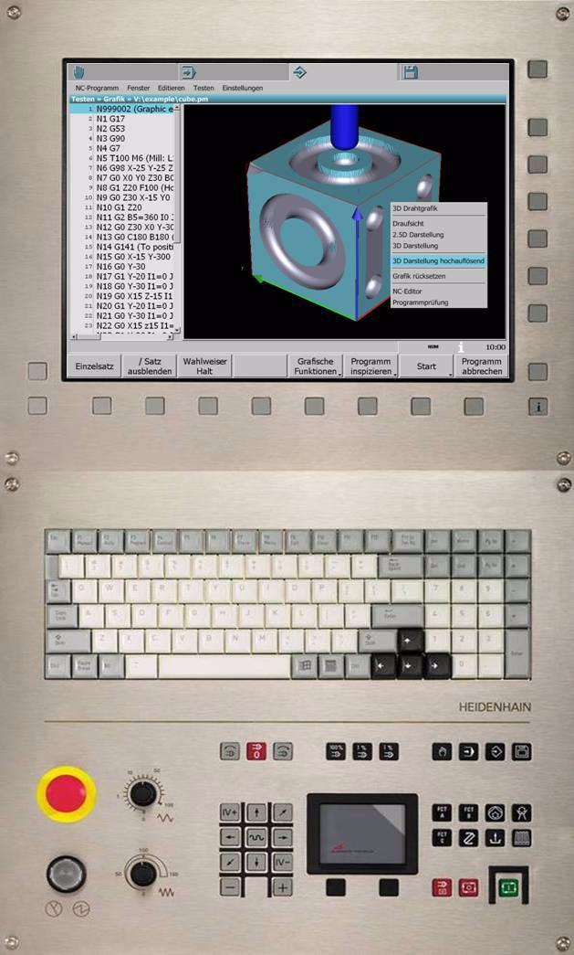
21 1.2 Visual Display Unit and Operating Panel The MillPlus features a color flat-panel display and an operating panel: Soft keys are assigned to the color flat-panel display The operating panel consists of a standard ASCII keyboard (NC part) and a machine operating panel Screen and NC keys The following keys are located on the display unit, the keyboard and the machine operating panel: 1 Select window 2 User soft keys 3 Soft-key row (NC functions) 4 Soft-key row (machine functions) 5 Info key 6 ASCII keyboard 7 Menu key 8 ALT key 9 Windows key 10 Applications key 11 Touchpad with selection and context buttons The functions of the individual keys are described on the inside front cover. 1.2 Visual Display Unit and Operating Panel Machine operating panel The machine keys are located on the machine operating panel: 12 NC switches: Emergency stop /NC on 13 Override knobs: Rapid traverse / Feed rate 14 Spindle control 15 Spindle-speed control 16 Main operating modes 17 Axis-direction keys 18 Keys for machine functions (PLC) 19 Start / stop keys The functions of the individual keys are described on the inside front cover. HEIDENHAIN MillPlus V600 21


22 1.3 Operating Concept 1.3 Operating Concept The MillPlus has four main operating modes: Manual, Automatic, Programming and Control (Setup). A uniform manner of operating the MillPlus is made possible by the basic components of the user interface. This operation consists of navigation through windows using the touchpad, keys and soft keys. Basic components 1 Main operating modes 2 Menu bar 3 Message line 4 System bar 5 Soft-key row (NC functions) 6 Soft-key row (machine functions) 7 Application window Main operating modes The four main operating modes are shown as tabs at the top of the screen. The active main operating mode is light gray. Switch between the main operating modes with the Manual, Automatic, Programming, and Control keys (on the operating panel and on the ASCII keyboard), or use the touchpad to click the main operating mode tabs on the screen. You can switch between the main operating modes of the MillPlus at any time, since they operate parallel to each other. Each mode maintains its current status when you switch to a different mode. An informational window can be opened in addition to the four main operating modes. Symbols The main operating modes are indicated with symbols on the tabs. Symbol Descriptions of the main operating modes Manual: Manual operation and automated sequences for setting up machines, workpieces and tools. Automatic: Breaking in workpiece programs, setting up the workpiece and automatic execution. The Manual operating mode is available during an interruption. Programming: Create, edit, simulate and manage NC programs. Control: Set up and manage the control, all control data, tool management, diagnostics and service functions Introduction

23 Status display in the main operating mode tab Symbols indicating the status of the respective main operating mode can appear in the main operating mode tab. These symbols are refreshed automatically. Symbol Description Program is running Program run is paused Program run is paused, and the program is open for editing 1.3 Operating Concept An error has occurred Warning Display of dwell time or time remaining Program status, such as End of program Menu bar The menu bar gives an overview of the menus available in the respective main operating mode. The menus are drop-down menus, meaning that a small window appears with the appropriate menu items when the menu is selected. This menu window shows the selectable functions and operating modes. Arrows in the menu window indicate that further window menus can be opened. All soft keys are deactivated while a menu window is open. Only once a menu has been selected or the menu bar deactivated do the soft keys become active again. HEIDENHAIN MillPlus V600 23

24 1.3 Operating Concept Navigation There are different methods for selecting the functions and operating modes of the menus: Touchpad Arrow keys Number keys 1 Touchpad Use the mouse pointer to select a menu from the menu bar. Click a menu item to open its menu window, and then move the mouse pointer to the desired function or operating mode. Click the function or operating mode to activate it. 2 Arrow keys Press the MENU key or the ALT key to open the menu Use the LEFT/RIGHT arrow keys to select a different menu from the menu bar Use the UP/DOWN arrow keys to select a function or operating mode from the menu window Activate the selected function or operating mode 3 Number keys Press the MENU key or the ALT key to open the menu Press the keys 0-9 in sequence to activate a function or operating mode from the menu Example: Press 2 and then 2 again to activate the Measure in jog function Introduction
25 Message line Error message The control displays current messages for the operator in the message line. Messages Machine Operation Programming Description Messages referring to the machine (PLC) Messages about the sequence of operations Programming errors or notes regarding the syntax The messages appear in the message line, with a yellow background A symbol may also be displayed in the main operating mode tab at the same time. Press CLEAR to remove the error message, or 1.3 Operating Concept Error info Press INFO to open the online help (see Online Help and Calculator on page 37). System bar The following symbols are shown in the system bar: Symbol Description Info key User soft keys Recording Keyboard: Number lock on Keyboard: Caps lock on Time HEIDENHAIN MillPlus V600 25
26 1.3 Operating Concept Soft-key row: NC functions Standard soft keys Use the soft keys to directly activate a function permitted in the active operating mode. The soft keys can also be activated with the touchpad. Symbol Description Soft key inactive Soft key active Soft key with an arrow in the corner indicates another soft-key row User soft keys You can also define your own soft keys, in order to specify optimized sequences. The user soft keys are superimposed over the standard soft keys if the USER key (at the edge of the display unit) is pressed, or if the same main operating mode is selected twice in a row. Select the main operating mode again to display the standard soft keys again. Soft-key row: Machine functions The machine soft keys activate machine-specific functions. The functions depend on the machine, and are specified by the machine manufacturer via the PLC. Application window You can enter your data or influence the sequences of the selected program directly in the applications window, depending on the active operating mode. Some examples of application windows are: Manual: Next to the graphic of the machine is an input window, in which you can enter commands and then run them. Automatic: The folders and files are displayed for selection of the NC program. Once a program has been selected, it is shown over the entire width of the window. Programming: The program opened in the editor is shown over the entire width of the window. If the graphic simulation function is activated, then a part of the window is used for this. Control (Setup): You can see and edit the tool data in a tabular view Introduction
27 1.4 Basic Operating Functions Typical functions are available in multiple locations on the MillPlus. The basic operating functions are: Input dialogs File manager Table editor NC editor Editing functions Shortcuts Popup windows Context menu Machine status display Online help User soft keys 1.4 Basic Operating Functions Input dialogs Support for data entry is available when creating a program in the program editor or with MDI, which helps you to structure the program block as needed. The level of support automatically adapts itself to the data entered in the block. The MillPlus offers a structured search view: the Function Explorer. The data-entry support is opened with the Dialog soft key. Function Explorer All functions and tools are collected by their functions into groups in the Function Explorer. This grouping makes it simple to find the function you are looking for. Press the ENTER key to open the selected function in the input dialog. The main groups are: G functions M functions T tools HEIDENHAIN MillPlus V600 27
28 1.4 Basic Operating Functions Support for data entry The level of support adapts itself to the respective contents of the program block when the Dialog soft key is activated. File manager Activates support for data entry. If a G function or an M function is entered (such as G81), then the input dialog window opens and the data can be entered via the keyboard. If only a G or an M is entered, or nothing at all, the Function Explorer opens automatically. Activates the Function Explorer. Select the desired function, and open it with the ENTER key. Saves the entered data in the program block. The input dialog window is closed. Data entry is cancelled in the dialog input window without saving the data in the program block. To ensure that you can easily find your files, we recommend that you organize your hard disk into directories. You can divide a directory into further directories, which are called subdirectories. Use the file manager to select a file. The file manager is available in the following operating modes: Automatic, via the menu bar: NC-Program > Select Programming, via the menu bar: NC-Program > Open or via the context menu Save as while a program is open Control, via the menu bar: NC-Explorer > File At the top of the list of drives you will find special drives with the opened programs in Automatic and Programming modes. Screen layout The file manager is divided into four window panes: 1 Explorer window with: List of drives Directories and subdirectories 2 Directory and file window with: List of files in the selected directory 3 File preview window The window shows a preview of the selected file 4 Filter window with: File name or a part of it to be searched for File type (*.pm, *.mm, etc.) 28 1 Introduction
29 Names of files and directories The name can consist of any letters and numbers. The characters * \ /? < > > are not permitted. Sequence of operations If you want to open a program, such as for program run in Automatic mode, first use the file manager to find the program. Sequence of operations with the ASCII keyboard Open the menu bar and select the NC-Program menu item. In this menu, choose the Select or Open functions. Navigation in the file manager Press TAB to switch the focus between the various panes. Use the arrow keys to open a drive or directory in the Explorer window [1]. Press the right arrow key again to switch the focus to the file window [2]. Press the left arrow key to switch the focus back to the Explorer window [1]. Press the ENTER key to open a file. Press ALT+arrow key in the filter window [4] to select a previous filter setting or file name. 1.4 Basic Operating Functions HEIDENHAIN MillPlus V600 29

30 1.4 Basic Operating Functions Table editor All tables with data regarding tools, datum shifts, etc, are available in the Control (Setup) main operating mode. Available tables: Tools Tool magazine Zero offsets Parameters Points Editing a table If a table is simply activated, then you can only view the information. The table itself has a gray background. If you want to edit a table (change the contents or add new data, for example), you must open the table by pressing the Edit soft key. You can make your entries in the table itself, or if the Dialog soft key is available, you can use the support for data entry. Finding Enter the string you want to search for in the Find window, and press the Find next soft key or press ENTER. You can repeat the search by pressing these keys repeatedly. Table settings The table view can be configured, i.e. you can optimize it for your application. The following settings are available: Column assignment and order: Position the mouse pointer on a column header and press the right mouse button to open the context menu. Select Column order. The Column order window shows the possibilities for configuration. Show columns: In the Columns to display window you can select which columns are to be shown. Column order: Indicate in Move column before what the order of the columns should be. Press Default to return to the default setting. Column width: Position the mouse cursor to the left or right edge of a column header. Press the left mouse button and drag the column to its desired width. Sort data: The data in a column is sorted in either ascending or descending order. An arrow in the column header shows the sort order. Click in the column header with the left mouse button to change the sort order Introduction
31 NC editor You can use the NC editor to create and edit NC programs. The program editor is available in the following main operating modes: Programming: Edit > NC-Editor Control: NC-Explorer > File The NC editor builds the program line by line. Each line consists of the NC block and a line number. The line numbers are automatically generated in ascending order. Use the keyboard to enter the data for the program block. Syntax highlighting The program blocks consist of various elements, such as G functions, comments, FMST, etc. These elements can be shown in different colors in the block. Select the Settings > Edit menu item to activate syntax highlighting and choose the colors. Syntax checking The correct syntax of a program can be checked while the blocks are being programmed. Select the Settings > Edit menu item to activate program checking. 1.4 Basic Operating Functions Line number and status symbol The gray column to the left of the program shows the line number, the line cursor, and a status symbol in front of the respective block. Status symbol: Symbol Description Warning, syntax error in the block HEIDENHAIN MillPlus V600 31

32 1.4 Basic Operating Functions Sequence of operations 1 Creating or editing a program In order to create an entirely new program, select the NC-Program > New menu item. In order to open an existing program, select the NC-Program > Open menu item. If you want to save the new or edited program, press the Save soft key. A window appears in which you can enter the program name and type. 2 Support during programming Open the input dialog window during program entry in order to simplify the entry of data. The grouping of functions makes it simple to find the function you are looking for. Press the INFO key or icon to call the soft keys for the calculator and the online programming aids Introduction
33 Editing functions You can use the editing functions to change the contents of one or more line in the MDI list or in programs: Soft key Description Mark this part of the block for cutting, copying or pasting Undo an action (CTRL+Z) Redo the undone action (CTRL+Y) Find any text within a program, and replace it with a new text if desired. A line number can also be searched for instead of a text. (CTRL+F) Cut the marked block parts (CTRL+X) Copy the marked block parts (CTRL+C) 1.4 Basic Operating Functions Inserted the marked block parts after the cursor position (CTRL+V) HEIDENHAIN MillPlus V600 33
 Copy Paste Undo Sometimes a popup window for a temporary function")
34 1.4 Basic Operating Functions Shortcuts: CTRL+... To speed operation, some functions can be activated via shortcuts. These functions are also available via soft key or over the context menu. Some frequently-used shortcuts: Shortcut CTRL+S CTRL+F CTRL+C CTRL+V CTL+Z Popup windows Description Save a program Find (replace) Copy Paste Undo Sometimes a popup window for a temporary function (such as searching, saving, etc.) appears within the current application. This popup windows appears on top of the current application window. A soft-key row belonging to the popup window is shown. Press ESC to close the popup window. In some cases you can switch the focus between the popup window and the application below it, such as the Find window in the NC editor. In these cases the MillPlus ensures that the correct soft-key row is always displayed. The focus cannot be changed away from some popup windows. Such popup windows must be closed first. Context menu Call the context menu via the ASCII keyboard (applications key) or by clicking the right mouse button. The context menu shows you a list of functions available in the active operating mode. The opened context menu closes automatically if you press ESC or if you select a function Introduction

35 Machine status display (dashboard) The status display informs you of the current state of the machine tool. The status display appears automatically in the following operating modes: Manual Automatic General status display 1 X, Y, Z, A, B, C: Axis positions Actual value Distance-to-go Symbol Description Axis clamping Axis transformation 1.4 Basic Operating Functions 2 T: Tool number Programmed tool Current tool Tool index 3 G53 - G59: Datum shift 4 G17 - G18: Machining plane 5 F: Feed rate Programmed feed rate Active feed rate Feed rate for plunging Override value for feed rate/rapid traverse Symbol Description G0: Rapid traverse G1: Feed rate 6 Program run time PM: Program T: Tool 7 G4: Dwell time HEIDENHAIN MillPlus V600 35

36 1.4 Basic Operating Functions 8 S: Spindle speed Programmed Spindle override Symbol 9 Program status Symbol Description M5: Spindle stop M3: Spindle left M4: Spindle right Description G73: Scale G73: Mirror G93: Rotate coordinate system G07: Tilt the machining plane Additional status displays Additional status displays, with detailed information about the program run, can be shown during program run and MDI. To switch the status display: Press the Status display soft key to show a new soft-key row, with a selection of the various possible status displays. Soft key Description The machine picture is the default display Information about the execution status: - Active G functions - Active M functions - Angle G7 - Rotation G93 - Mirroring G72 - Scaling G73 Information about offsets: - Axis positions G52, G54, G92+G93 - Tool Information about E parameters: - Parameters E+ES 36 1 Introduction
37 1.5 Online Help and Calculator INFO functions At all times and in all main operating modes, you can call additional online help or a pocket calculator. Press the INFO key or icon, and then the appropriate soft key, to select one of these functions. Soft key Call the online help and calculator Description Call online programming support Call online operating support Call explanations and fixes in case of error messages Call the calculator 1.5 Online Help and Calculator The online programming and operating support appear in a popup window. You can use the mouse pointer to change the size and position of this window. Programming support Press INFO and then the Programming support soft key to find all programming functions, including the programming language, of the MillPlus online. This online support can be of assistance while you are entering a program. The online help is context-sensitive: if a program is being entered, then the online help jumps directly to the detailed information about a function. If there is no programming context, then the online programming support opens with the overview of function groups. Operating support Press INFO and then the Operating support soft key to find all operating functions of the MillPlus online. HEIDENHAIN MillPlus V600 37
38 1.5 Online Help and Calculator Error support In case of an error, the MillPlus automatically shows a brief description of the error in the message line above the soft keys. Error messages occur if: Incorrect data was entered during programming Logical errors arise in the program during program testing or program run System errors during operation If you require additional information about an error message, press INFO and then the Error support soft key. A popup window appears: List of error messages A description of the error cause and error fix for each error. Calculator The MillPlus features an integrated pocket calculator with the basic mathematical functions. The calculator can be called with INFO from any location. You can use the calculator to calculate intermediate results during programming. These values can be sent directly to the cursor position in the program editor with the Insert result soft key. Click the View button with the mouse to cycle through the three levels of calculator functions Introduction
39 1.6 User Soft Keys User soft keys, which you define yourself, are available in addition to the standard soft keys. These user soft keys enable quick and customized operation anywhere on the control. Operation User soft keys that are superimposed over the standard soft keys are available in all operating modes. Use this feature to create your own operating level, where you can have numerous operating steps or sequences be performed via a soft key. Active the user soft keys by: Pressing the USER SOFT KEYS key at bottom left on the display unit, or by Pressing an operating mode key twice, or by Clicking an active operating mode tab with the mouse. The user soft keys symbol appears in the system bar. 1.6 User Soft Keys The standard soft keys appear again after a user soft key has been activated, or after a main operating mode has been selected again. Recording a user soft key After placing the mouse pointer over a new user soft key that you want to define, open the context menu. Activate either the Record UK or Cancel record UK function. The recording symbol appears in the system bar. All keys pressed (on the ASCII keyboard as well as the operating panel, except for the Start and Stop keys) and all mouse clicks are recorded in sequence. Stop recording by clicking the recording symbol. You can then assign a text or an image to the user soft key. HEIDENHAIN MillPlus V600 39
40 1.6 User Soft Keys Text or image for user soft keys You can choose to assign texts or images to user soft keys. The text or the image file name is assigned in a table in the Control (Setup) operating mode. The image file must be saved in the Userkeys directory on the V drive. Select the Control (Setup) main operating mode. Select the following function from the menu: Installation >> Configuration >> User soft keys Open the table for editing. Deleting a user soft key You can delete a user soft key from the table in the Control (Setup) main operating mode. Select the Control (Setup) main operating mode. Select the following function from the menu: Installation >> Configuration >> User soft keys Open the table for editing. Remove the text and image name of the recording, and Delete the selected recording Introduction


 Defining coordinates The coordinates of points in space (3-D) define traverse paths along the axes. The axis coordinates are in one of three planes (XY plane, ZX plane, YZ plane).")
41 1.7 Coordinates and Reference System Axis configuration A machine has three linear principal axes (X, Y Z), which are mutually perpendicular. The orientation of these axes is determined by the Z axis, which always runs parallel to the machine tool s spindle. The X axis is that with the greatest traverse path perpendicular to the Z axis. A rotary axis can be assigned to each principal axis. (top figure) Coordinate system The CNC can connect points by linear and circular paths of traverse (interpolations). Workpiece machining is programmed by entering the coordinates for a succession of points and connecting the points by linear or circular paths of traverse. The positions of the CNC machine tool s axes are defined by the following standards: ISO 841, DIN and EIA RS-267-A. (center figure) Defining coordinates The coordinates of points in space (3-D) define traverse paths along the axes. The axis coordinates are in one of three planes (XY plane, ZX plane, YZ plane). The coordinates can be entered using absolute, incremental, Cartesian or polar coordinates. 1.7 Coordinates and Reference System G7 coordinates The position display on the screen can toggle between the position in the G7 plane (Xp, Zp) or the machine coordinates (X, Y). Both refer to the active datum G52 + G54 + G92/G93. (bottom figure) HEIDENHAIN MillPlus V600 41
 and the machinebased reference point (R) is saved via machine configuration data.")

42 1.7 Coordinates and Reference System Datums In order to determine the machine datum, a reference run must first be performed after switch-on. The machine datum is specified, since the offset data between the machine datum (M0) and the machinebased reference point (R) is saved via machine configuration data. R = machine reference point M0 = machine datum W = program datum The operator specifies a program datum (W) for the workpiece, relative to which the workpiece dimensions are measured. This program datum must also refer to the machine datum, which can be specified with the G52 and/or G54...G59 functions. Machine-based reference point (R) Every traversable axis of a machine tool has a stationary point designated as the reference point. The reference points of all axes together form the machine-based reference point (R) (bottom figure). During the reference run (see Crossing over the reference point on page 47), the tool traverses to the reference point of each respective axis. Once this point is reached, the CNC automatically zeroes the axis. The positions of the software limit switches are specified Introduction
43 Manual Operating Mode
44 2.1 Introduction 2.1 Introduction The Manual operating mode provides functions for simple machining operations, for setting up the machine, and for setting up and premachining workpieces. In this operating mode, you operate and move the machine axes and the spindle manually. G-code commands for positioning the axes and machining simple workpieces as well as for machine and tool functions are entered and executed blockwise. You can intervene or interrupt program run, and then resume or cancel program run. You can save the most important machine functions and machining operations in an MDI list and reuse the NC blocks from this list at a later time. Menu bar In the Manual operating mode, select subordinate operating modes or functions from the pull-down menus in the menu bar. Menu Workpiece Tool MDI Machine tool Settings Description Workpiece setup: Setting the zero points and workpiece measurement Tool setup: Tool measurement, entry of tool technology data and setting the plane Manual data input and execution of instruction sets Machine-related functions: Reference-point traverse, axis diagnosis and shutdown of the MillPlus Settings parameters for the functions in the Manual operating mode 44 2 Manual Operating Mode
45 Menu items The menu items identified by an asterisk (*) are not supported by this software version. The pull-down menus contain the following menu items providing the functions or operating modes described below: Workpiece menu Touch side Description Setting the workpiece zero point with a tool 2.1 Introduction Determine center Preset axes Measure side * Setting the workpiece zero point in the center of a circle or rectangle by using the tool Setting the current position as the workpiece zero point Setting the workpiece zero point with a touch probe Tool menu FST entry Measure in jog Set plane Description Manual data input and execution of technological functions Tool measurement by touching the workpiece with the tool Activation of a working plane MDI menu Free entry Description Manual data input and execution of instruction sets Machine tool menu Reference point NC shutdown Description Determining the axis position through reference point traverse Shutting down the control in order to switch off the machine Settings menu Jogging Description Axis settings for jog operation HEIDENHAIN MillPlus V600 45
, the startup screen (Log On to Windows) appears after switch-on.")
46 2.2 General Functions 2.2 General Functions Switch-on Switch-on and traversing the reference points can vary depending on the machine tool. Refer to your machine manual. Switch on the power supply of the machine and the MillPlus. On a MillPlus with dual-processor system (Windows XP), the startup screen (Log On to Windows) appears after switch-on. Enter the appropriate data in User name, Password and Log on to. For the data to be entered, refer to your machine manual, the system administrator or your machine supplier. Booting the MillPlus Release the EMERGENCY STOP switch. Press and hold the MACHINE ON button. Press the CLEAR key. The MillPlus starts up in the Manual operating mode and is now ready for operation. You can execute the following functions: Positioning the axes with the AXIS-DIRECTION KEYS Crossing over the reference points 46 2 Manual Operating Mode
47 Crossing over the reference point After the MillPlus has started up, all axes must cross over the reference point. You can move the axes manually, but you cannot execute any commands in MDI or any programs in Automatic operating mode until the reference points have been crossed over. Axes that are equipped with absolute encoders do not have to cross over the reference points. If all axes are equipped with absolute encoders, the MillPlus is ready for operation immediately after the machine control voltage is switched on. Standard working plane The reference run can be executed separately for each individual axis or for more than one axis simultaneously. Select all axes. 2.2 General Functions Select one axis. After you have pressed the START key, the selected axes simultaneously move to the reference point at feed rate. After the reference point has been crossed over, the MillPlus executes a machine-dependent rapid traverse movement to a fixed position. The MillPlus is now ready for operation in the Manual operating mode. The reference points need only be crossed over if you want to traverse the machine axes. If you only want to edit or test programs, select the Programming operating mode after switching the machine control voltage on. You can then cross over the reference points later. Traversing the reference point in a tilted working plane The tilting of the plane is automatically cancelled when the reference point is traversed in an axis. HEIDENHAIN MillPlus V600 47
48 2.2 General Functions Switch-off To prevent data from being lost at switch-off, the operating system of the MillPlus needs to be shut down properly: Select the Manual operating mode. Select Machine tool > NC shutdown. Shut down the MillPlus. Inappropriate switch-off of the MillPlus can lead to data loss. Moving the machine axes: Jogging Manual traverse with the axis-direction keys can vary depending on the machine. The machine tool manual provides further information. The axes are moved with the axis-direction keys: in continuous jog mode in incremental jog mode ( ), or with a free increment at a predefined feed rate, or at a programmed feed rate See Jogging on page 63. Continuous jog Use the axis-direction keys to move a single axis or more than one axis simultaneously. Press the Step/Continue soft key to select the continuous jog mode. Press the axis-direction key and hold it as long as you wish the axis to move The axis feed rate is adjusted with FEED RATE OVERRIDE (0-100%). If you press an axis-direction key and the RAPID TRAVERSE key simultaneously, the axis moves at rapid traverse speed Manual Operating Mode
49 Incremental jog In incremental jog mode, you move a machine axis by a preset distance. Press the Step/Continue soft key to call the Step soft keys. Set the jog increment with the Step soft key, for example. Press the axis-direction key. The axis moves in steps of Moving the axes in a tilted plane Using the axis-direction keys, you can also move the axes in a tilted plane. When the tilted plane is active, you must switch on jog movement in the tilted plane by pressing the soft key showing the tilted plane symbol. When movement in the tilted plane is active, "P" is displayed next to the axis designations, and the yellow symbol for tilted plane appears in the machine status display. Press the Step/Continue soft key in the Manual operating mode. 2.2 General Functions Select tilted plane. Traversing with the HR 410 electronic handwheel The portable HR 410 handwheel is equipped with two permissive buttons. The permissive buttons are located below the star grip. You can only move the machine axes when a permissive button is depressed (machine-dependent function). The HR 410 handwheel features the following operating elements: 1 Emergency Stop button 2 Handwheel 3 Permissive buttons 4 Keys for axis selection 5 Keys for actual-position capture 6 Keys for defining the feed rate (slow, medium, fast; the feed rates are set by the machine tool builder) 7 Direction in which the MillPlus moves the selected axis 8 Machine functions (set by the machine tool builder) The red indicator lights show the axis and feed rate you have selected. HEIDENHAIN MillPlus V600 49
50 2.2 General Functions Spindle speed S, feed rate F, tool T and machine function M Application In the Manual operating mode the values for tool T, machine function M, spindle speed S and feed rate F are entered with FST entry or MDI Free Data Input. The MillPlus provides standard and machine-related machine functions M. The machine tool builder determines which machine functions M are available on your control. Entering values with FST or MDI > Free entry Enter the following values: 1 Tool call T with machine function M 2 Spindle speed S, alternatively with a machine function M 3 Feed rate F Executing the values entered Start spindle rotation at the entered speed S, or start tool change with the entered tool number T. Execute feed rate F, and move the axis/axes at the entered feed rate if axis/axes are programmed. Adjusting rapid traverse, feed rate and spindle speed The override knobs are located on the machine operating panel. With the override knobs, you can vary the spindle speed S and the feed rate F: Rapid traverse from 0% to 100% Feed rate F from 0% to 150% With the spindle keys, you can vary the value set for spindle speed S: Spindle speed S to 100% Increase spindle speed S (%) Reduce spindle speed S (%) 50 2 Manual Operating Mode
51 Positioning manual axes Manual axes are rotary or linear axes that are equipped with a position measuring system, but they do not have a servo drive. In Manual operating mode, manual axes can be moved to the desired position at any time. Programming manual axes If manual axes are positioned via the program, the MillPlus will inform the machine operator about it. Program run stops and the following messages appear: The status bar displays the "Positioning manual axis" message. The distance-to-go display for the affected axes is highlighted in yellow. The machine operator moves the manual axis/axes until the distanceto-go value is 0. Once the distance-to-go value is within a certain tolerance, the distance-to-go display turns green and program run can be resumed. If the manual axis is not within the tolerance when program run is restarted, the MillPlus issues the error message "Manual axis not in position". 2.2 General Functions If the movement of a manual axis is smaller than the tolerance window, the MillPlus nevertheless stops program run and the distance-to-go display is highlighted in green. If the difference between the nominal position and the actual position is less than the programming format (0.001 or degrees), the deviation is not treated as a movement and does not lead to a program stop. It is not allowed to interpolate NC axes and manual axes. The MillPlus then displays the error message "Axis and manual axis not permitted." HEIDENHAIN MillPlus V600 51
52 2.2 General Functions MDI: Free entry Manual data input and execution of instruction sets. This operating mode provides the following functions: 1 Entry and execution of individual blocks 2 The blocks entered are saved in the MDI list and can be reused later. Programming and executing simple machining operations The MDI operating mode enables you to set up the machine and to execute simple machining operations. The individual instructions (ISO or cycles) are entered blockwise in the MDI input window. Then press the START key to have the MillPlus execute the respective block. The block is saved in an MDI list (see MDI Menu on page 61). The MDI list is saved in a file on the Work drive. The $MDI.pm file can be opened in the program editor. Limitations of MDI Contour programming, programming graphics, subprograms, program section repeats, and path compensation are not available. Structure of the MDI list The MDI list is a list of instruction sets. The blocks entered need not be related to each other. They may be listed in any sequence and do not make up an NC program. Support for data entry You can use the support for data entry, while you are entering data. The level of support adapts itself to the respective contents of the program block. Use the function explorer to select a function and enter the appropriate data in the input dialog. See Function Explorer on page 27 and Input dialogs on page Manual Operating Mode
53 Executing a block Press the START key to execute the block you have entered, or a block you have selected from the MDI list. After the block has been executed, the cursor remains on the block. Status information During the execution of a block, the MillPlus provides detailed information on the current machining status. For example, the modal G functions and the current contents of E parameters are shown. See Additional status displays on page 36. Edit functions The Edit functions allow you to change the contents of one or more lines in the MDI list. The Cut, Copy, and Paste functions are available. You can also find a text in the MDI list. See Editing functions on page General Functions HEIDENHAIN MillPlus V600 53
54 2.2 General Functions Setting the zero point When the MillPlus is ready for operation and the reference points have been crossed, the zero points can be set. You fix a zero point by setting the MillPlus display to the coordinates of a known position on the workpiece. The measured zero point shift is saved as the active zero point G54- G59 or G54 I... Preparation Clamp and align the workpiece. Insert a tool with known radius and length. Select the desired zero point G54-G59 or G54 I... Zero point setting with the axis-direction keys Protective measure If the workpiece surface must not be scratched, you can lay a metal shim of known thickness d on it. Then enter a nominal value that is larger than the desired value by the value d. In the Manual operating mode, the Workpiece menu offers various functions for setting the zero point. See Workpiece Menu on page Manual Operating Mode
55 Tool measurement Each tool is identified by a number. The associated tool data are saved in the tool table. When a tool is inserted from the tool magazine into the spindle with the Txx and Mxx commands, the tool data are assigned to the active tool. The MillPlus can measure tool data with Tool > Measure in jog in the Manual operating mode (see Tool Menu on page 59). with MDI > Free entry in the Manual operating mode (see MDI Menu on page 61). during program run in the Automatic operating mode. See the tool measurement cycles in the G600-G699 Measuring Cycles chapter of the Programming manual. 2.2 General Functions HEIDENHAIN MillPlus V600 55

56 2.3 Workpiece Menu 2.3 Workpiece Menu Workpiece setup: Zero point setting and workpiece measurement The Workpiece menu contains the following menu items: Touch side Determine center Preset axes Touch side Setting the workpiece zero point with a tool. You set the workpiece zero point by touching a workpiece edge with the tool. Enter the nominal value and confirm the axis traverse direction. The zero point is saved as the active ZPS number. Activating the zero point The zero point is saved as a ZPS number. In order to activate the zero point, the corresponding ZPS number must be activated in the zero point table. Open the zero point table. Use the arrow keys to select the zero point number (e.g. G54 I1) and activate it. The zero point (G54 I1) is displayed in the machine display. Touching a workpiece edge In the input window, enter the nominal value of the workpiece edge to be touched. Using the axis-direction keys, move the tool to the workpiece edge and touch (scratch) it with the tool. Confirm the appropriate axis traverse direction by soft key. This saves the zero point of the respective axis as the active ZPS number. The other axis reference values are determined in the same manner Manual Operating Mode
57 Determine center Setting the center of a workpiece with a tool. You determine the center of the workpiece as the workpiece zero point by touching two opposing workpiece edges with the tool. Enter the nominal values and confirm the axis traverse direction. The center is determined and saved as the active ZPS number. Activating the zero point number The zero point is saved as a ZPS number. In order to activate the zero point, the corresponding ZPS number must be activated in the zero point table (see Touch side on page 56). Touching a workpiece edge Using the axis-direction keys, move the tool to the first workpiece edge and touch (scratch) it with the tool. 2.3 Workpiece Menu In the input window, enter the nominal value of the probed workpiece edge. Confirm the appropriate axis traverse direction by soft key. Move the tool axis to the opposite workpiece edge and touch (scratch) it with the tool. In the input window, enter the nominal value of the probed workpiece edge. Confirm the appropriate axis traverse direction by soft key. The measured center is saved as a ZPS number. The other workpiece centers are determined in the same manner. HEIDENHAIN MillPlus V600 57
58 2.3 Workpiece Menu Preset axes Setting the current position with a tool. To determine the actual position value, move the tool manually to any desired position. Enter the desired nominal position value. The value is saved as the active zero point. Activating the zero point The zero point is saved as active zero point G54-G59 or G54 I.... In order to activate it, the corresponding ZPS number must be activated in the zero point table (see Touch side on page 56). Moving to a position Enter the nominal position value in the input window. Using the axis-direction keys, move the tool to any desired position. The zero point is set in the axes in which the nominal value is entered Manual Operating Mode

59 2.4 Tool Menu Tool setup: Tool measurement, entry of tool technology data and setting the plane. The Tool menu contains the following menu items: FST entry Measure in jog Set plane 2.4 Tool Menu FST entry Entry and execution of technological machine functions. You can enter machine functions, such as tool Txx, spindle speed Sxxxx, machine functions Mxx and feed rate Fxxxx. Press START to execute the functions. Please keep in mind that when you start the functions, the spindle may start, and the axes will move to the tool change position if a tool is entered. Entering and executing technological functions Select Tool in the menu bar. Select FST entry and press ENTER to activate it. Enter the data for T, M, S and F in the input window. After you have pressed the START key, the machine will execute the functions. The current values for F, S and T are displayed in the machine display. Finding tool Txx If you want to select the tool from the tool table, proceed as follows: Open the tool table. Select the tool number Txx with the arrow keys. The tool number from the tool table is transferred to the FST entry window. HEIDENHAIN MillPlus V600 59
60 2.4 Tool Menu Measure in jog Tool measurement by touching the workpiece with the tool. To measure a tool, touch the workpiece at a known dimension with the tool tip in the working plane or tool axis. When you press a soft key for the axis traverse direction, the MillPlus calculates the tool compensation values R or L from the nominal value entered. You cannot measure the tool until you have inserted the tool into the spindle and activated the tool. The tool change function can vary depending on the individual machine tool. The machine tool manual provides further information. Measuring the tool radius Select Tool in the menu bar. Select Measure in jog and press ENTER to activate it. In the input window, enter the nominal value of the workpiece edge to be touched. Using the axis-direction keys, move the tool to the workpiece edge and touch (scratch) it with the tool in the working plane. Press the soft key for the corresponding axis traverse direction (X or Y) in the working plane. The MillPlus calculates the tool radius R for this axis and stores it in the tool memory. The compensation value for the measured tool is displayed in the tool data window. To measure the tool length L, use the same procedure (touching the workpiece) in the tool axis direction. Set plane Activate the working plane. The working plane is switched and activated with the Plane nn soft keys. Setting the plane (e.g. XY) Select the Plane XY. Activating the plane. The machine display shows the current plane Manual Operating Mode
61 2.5 MDI Menu Manual data input and execution of instruction sets The MDI menu contains the following menu item: Free entry Free entry 2.5 MDI Menu Manual data input and execution of individual functions and machining operations. In the Free entry window, you enter the individual instructions block by block. Then press the START key to have the MillPlus execute the respective block. The block is saved in an MDI list.. See MDI: Free entry on page 52. Entry and execution Select MDI in the menu bar. Select Free entry and press ENTER to activate it. Use the keyboard to enter the data in a line of the MDI list. Press the START key to execute the block. Support for data entry You can use the support for data entry, while you are entering data. See also Input dialogs on page 27. Activate support for data entry. The level of support adapts itself to the respective contents of the program block. 1 Entered data is known (e.g. G81): The support window shows the input window for the function (G81: Drilling/Centering) 2 Entered data is not known (e.g. Gxx or empty block): The function explorer displays an overview of all G code functions. After the entry has been concluded, the MillPlus returns to the Free entry window. The block is saved and ready for execution. HEIDENHAIN MillPlus V600 61
62 2.6 Machine Tool Menu 2.6 Machine Tool Menu Machine-related functions: Reference point traverse, axis diagnosis and shutdown of the MillPlus. The Machine tool menu contains the following menu items: Reference point NC shutdown Reference point Determining the axis position through reference point traverse. After the MillPlus has started up, all axes must cross over the reference point (see Crossing over the reference point on page 47). If you want to repeat the reference run of the axes, proceed as follows: Select Machine tool in the menu bar. Select Reference point and press ENTER to activate it. Select One axis or All axes to traverse the reference point in one axis or in all axes. After the axis/axes has/have crossed over the reference point, the current position will be displayed in the actual-value display. Axes that are equipped with absolute encoders do not have to cross over the reference points. If all axes are equipped with absolute encoders, the MillPlus is ready for operation immediately after the machine control voltage is switched on. NC shutdown Shutting down the MillPlus properly. Select Machine tool in the menu bar. Select NC shutdown and press ENTER to activate it. Press the OFF soft key to switch the MillPlus off Manual Operating Mode

63 2.7 Settings Menu Settings parameters for the functions provided by the menus and menu items in the Manual operating mode. The Settings menu contains the following menu items: Jogging Jogging Axis settings for operation in jog mode. The jog feed and the Free step value for the axes are defined in this window. Select Settings in the menu bar. Select Jogging and press ENTER to activate it. The MillPlus opens the Settings >> Jogging window. Enter the nominal value of the Free step value in the input window. Press the Step/Continue soft key to call the soft key on which the step size is displayed. Possible settings in the Settings >> Jogging window: 1 Free step value Set the free step value. The step size entered can be selected by pressing the Step/Continue soft key and then the corresponding soft key (F5). 2 Jog feed Select a predefined or programmed feed rate for jogging. 3 Select axis Assign the axis to the freely assignable axis-direction keys +/. 2.7 Settings Menu HEIDENHAIN MillPlus V600 63
64
65 Automatic Operating Mode
66 3.1 Introduction 3.1 Introduction In the Automatic operating mode the MillPlus runs a part program in single-block or full-sequence mode to its end. For this the program needs to be selected from the work folder and be prepared by using the file manager. Programs that were created with the MillPlus or with an external CAD system ensure high-accuracy machining at high speed. The mid-program startup function (block search) enables you to run a part program from any desired block. The MillPlus scans the program blocks up to that point. Menu bar In the Automatic operating mode you can select a subordinate operating mode or a function by using the menu bar or the menu items. Menus NC Program Execution Test Settings Description Select and activate part programs. Run the active program in the Machining or Dry run mode of operation. The machine axes are moved. Functions for program testing before machining. The machine axes are not moved. Settings for the Automatic operating mode Automatic Operating Mode
67 Menu items The menu items identified by an asterisk ( * ) are not supported by this software version. The pull-down menus contain the following menu items providing the functions or operating modes described below: NC Program Select Description Select an NC part program by using the file manager. 3.1 Introduction Autostart * Remote Ext. program call * Last selected programs Automatic start of an NC program at a programmed time. After activating remote control, you can control all functions from a DNC computer. Functions, such as editing the tool memory, are deactivated at the operating panel of the control. Select an NC program by using program call numbers that are entered in the CNC's memory and activated by the PLC. Quick selection of the four last NC programs that were selected. Execution Machining Dry run * Description Machining of NC programs. Test run of an NC program without machine movements. Test Simulation * Program analysis * Description Graphic testing of NC programs. Preliminary program analysis in order to avoid interruptions in the machining process. Settings NC program * Execution Test * Description Set the font size. Program depiction: Show the program structure next to the program Settings for the program test. HEIDENHAIN MillPlus V600 67
68 3.2 General Functions 3.2 General Functions Program selection If you want to run a program on the machine, you must first select and activate the program. To select the desired program, select the File manager The file manager manages all programs stored on the drives and in the folders. Use the mouse or the ASCII keyboard to select and open a program. Quick selection of the last 4 programs that were selected When you select the Select menu item, the last programs that were selected are listed at the bottom of the window (including the path). You can open a program directly by selecting it from the list. Program execution The program you have selected is displayed in the program window. When the program activates subprograms during program run, the active subprogram is displayed in an additional window to the right of the main program. After the subprogram has been finished, the additional window is automatically closed. Program structure You can also display the program structure in addition to the selected program. Some important features of the main program and the subprograms, such as tool change, subprogram call, repetitions, etc. are listed in the program structure. This gives you a quick overview of the program structure, and you can see the program sequence during program run. You can also use the program structure for mid-program startup. Select Settings>> Execution to activate the program structure. Automatic program run (program run, full sequence) To start the active program, press the START key. In the automatic program run mode, the MillPlus executes a part program continuously to its end. During program run, the block being executed is highlighted by the cursor. If the Program structure window is also displayed, the highlight is on the block with the active tool. Program run, "Single step" In the program run "Single step" mode, you must start each block separately by pressing the START key Automatic Operating Mode
69 Interruption of program run There are several ways to interrupt program run: Programmed interruption Interruption with feed rate STOP key, or feed rate + spindle STOP key Switching to program run "Single step" Error message Programmed interruption You can program interruptions directly in the part program. The MillPlus interrupts the program run at a block containing one of the following entries: Miscellaneous functions M0, M01 or M30 (program end) Miscellaneous function M06 (determined by the machine tool builder) 3.2 General Functions Interruption with feed rate STOP key, or feed rate + spindle STOP key Feed rate STOP key: The block that is currently being executed by the MillPlus is interrupted. The axis movements stop, and the spindle keeps rotating. Feed rate + spindle STOP key: The block that is currently being executed by the MillPlus is interrupted. The axis movements stop, and the spindle stops. In either case, the "Program stopped" symbol appears in the tab showing the main operating mode. You can resume or cancel program run from this position. Switching to program run "Single step" You can interrupt a program that is being run in the automatic program run mode of operation by switching to the program run "Single step" mode. The MillPlus interrupts the machining process at the end of the current block. Press the START key to execute the next block. Breakpoints You can use breakpoints to interrupt program run without changing the program. The program will then be executed up to the breakpoint and will not be continued until you restart it. See Program breakpoint on page 75. Error message The machining process may be interrupted, depending on the error message class, the machine error or the NC error. The axis movements are stopped, and the spindle stops. The "Program error" symbol appears in the tab showing the main operating mode, and an error message appears in the status bar. HEIDENHAIN MillPlus V600 69
70 3.2 General Functions Moving the machine axes during an interruption You can retract the machine axes during an interruption in the same way as in the Manual operating mode. Danger of collision When retracting the axes, ensure that you press the correct axis direction keys that match the current coordinate system. The tool should be retracted first, and then the axes should be moved away from the workpiece. Please keep in mind the workpiece form and the workpiece position. In a tilted working plane (G7), you can use the Jog in G7 plane" soft key to switch between the tilted working plane and the machine coordinates. Intervening program run It may sometimes be necessary to edit the machining parameters during program run. For example, changes can be made in the: MDI mode of operation Tool parameter table or workpiece zero point table Program editor In order to edit a program or table, you must first interrupt the program run, and then activate the program by pressing the Intervene program run soft key. Activate intervention. You also have other possibilities to interrupt the program run: 1 STOP key: Program run is immediately interrupted Press the STOP key. (The current block will not be executed to its end). Activate Single step mode. Press the START key to execute the interrupted block to its end. 2 Program run "Single step" Activate Single step mode. The current block will be executed to its end Automatic Operating Mode
71 Resuming program run after an interruption You can resume program run after an interruption. The possibilities to resume program run vary, depending on the point of interruption. 1 Resuming program run at the point of interruption in the block. For this, the block may consist of One single instruction, such as a contour section, in the main program or subprogram. A cycle, such as a drilling cycle, in the main program or subprogram. 2 Resuming program run at the beginning of the contour section block, the macro block or the cycle block. This means that some machining operations will be repeated. Program run is therefore interrupted, and the Block search function is used to find the beginning of the block. 3.2 General Functions Resuming program run with the START key Resume program run soft key: The Distance to go window shows the distance from the restart position: All axes soft key: Move the axes in the sequence that the MillPlus suggests. Press the START key. Restart? soft keys: Move the axes in any sequence. Select the axis/axes by soft key and activate them with the START key. You can resume program run by pressing the START key if the program was interrupted in one of the following ways: The STOP key was pressed. An interruption was programmed. If you have moved the machine axes (in the Manual operating mode) during the interruption, you can resume program run (in the Automatic operating mode) in the following way: Danger of collision Move the axes in the sequence shown in the Distance to go window, and not according to the positioning logic. Press the START key to resume program run. HEIDENHAIN MillPlus V600 71
72 3.2 General Functions Mid-program startup (block search) Startup point The mid-program startup function (block search) enables you to run a part program from any desired block. The MillPlus scans the program blocks up to that point. Activate mid-program startup. There are several ways to select the startup point: Place the cursor on the desired block in the part program. Place the cursor on the desired instruction in the program structure, which compactly lists the important instructions. If subprograms are used, you can open a subprogram using the program structure, and then set the startup point in the subprogram. Use the Find soft key to search for a character string (instruction or text) or a line number in the program. You can also use the Extended search soft key to enter additional search criteria, such as the name of the program or subprogram, the desired line number or the number of repetitions at the startup point. Mid-program startup (block search) After selecting the startup point, you can choose between two possibilities of getting to the startup point: If you press the Go to cursor soft key, the MillPlus does not scan the program up to the selected block (without calculation). Program run starts directly from the selected block. If you press the Search to cursor soft key, the MillPlus scans the program up to the selected block (block search with calculation). After that, program run starts from the selected block. Please note that there is a danger of collision, especially when mid-program startup without calculation (Go to cursor) is used. The MillPlus therefore displays a warning. Symbol Description Caution Danger of collision: Search program without calculation 72 3 Automatic Operating Mode

73 Starting program run You cannot start program run from the selected block until the corresponding MSTH functions and the tool position have been reached. The MillPlus displays a suggestion in a pop-up window. You can accept the suggestion by soft key and execute it by pressing the START key. But you can also adapt the suggestion to your requirements. 1 MSTH functions: Execute the MSTH functions that have been determined through block search with calculation. In the MSTH function window, select the MSTH functions to be executed: Select all MSTH functions (accept the suggestion displayed by MillPlus). Remove an MSTH function. All other functions suggested by MillPlus are accepted. 3.2 General Functions Select one single MSTH function. Press the START key to execute the selected MSTH functions. After all selected MSTH functions have been executed, the Distance to go window appears. 2 Distance to go: Move the axes from the current position to the startup position. Select the axes: All axes soft key: Move the axes in the sequence suggested by the MillPlus in the window. Restart? soft keys: Move the axes in any sequence. Press the START key to move the selected axes to the startup position. Danger of collision Move the axes in the sequence shown in the Distance to go window, and not according to the positioning logic. After all axes have been moved to the startup position, you can start program execution. Safety notes and general tips With mid-program startup, program run is continued from the selected block. To be able to execute this block, the MillPlus may have to execute functions that cause collisions. These can be functions, such as tool change (approaching the tool change position), rotating the (swivel) head and (rotary) table, switching or tilting the working plane, approaching the workpiece on a straight path and continuing the machining process, etc. HEIDENHAIN MillPlus V600 73
74 3.2 General Functions Before mid-program startup, in the Manual operating mode the (rotary) table and the (swivel) head with tool must be retracted to a position from which the abovementioned functions can be executed without problems and without a danger of collision. It is recommended preparing the machine at the startup position in such a way that the program can be continued from the startup position without problems. Optional block skip In a test run or program run, the MillPlus can skip over blocks that begin with a slash (/): Selectable stop (Selective wait) The MillPlus optionally interrupts the program run or test run at blocks containing M Automatic Operating Mode
75 Program breakpoint Use this function to set breakpoints at program blocks. The program will then be executed up to the breakpoint and will not be continued until you restart it. You can set multiple breakpoints in succession. Breakpoints are not saved in the program. The breakpoint is identified by a red dot in front of the respective block. The red dot is displayed in a column to the left of the program. You can clear all breakpoints simultaneously, or you can clear an individual breakpoint. For this, you must first activate the program with the Intervene program run soft key. Define the breakpoint. There are several ways to find the block in which you want to set a breakpoint: Use the cursor, the PAGE UP/DOWN key or the mouse to navigate through the program. Use the program structure to navigate. Use the Find soft key to search for a character string or a line number. 3.2 General Functions HEIDENHAIN MillPlus V600 75
76 3.3 NC Program Menu 3.3 NC Program Menu Select and activate part programs. After selection, the MillPlus automatically switches to the active mode of operation (Machining, Dry run or Test). Default setting: Machining mode of operation. The NC Program menu contains the following menu items: Select "Last selected programs" Select Select a part program from the program memory. Use Select to select an existing part program in the file manager. Opening the file manager Select NC Program in the menu bar. Select the Select menu item, select a program in the file manager and press ENTER to open it. Use the file manager to find the desired program and press ENTER to activate it. For navigation, see File manager on page 28. Running a part program The selected part program is displayed in the program window. Depending on the operating mode (Machining, Dry run, Test) that was last active, you can start the part program. Press the START key to run the part program in full sequence or single step mode. For more information about executing a part program, see Execution Menu on page Automatic Operating Mode
77 Last selected programs The menu displays a list of the four last programs that were active in the Automatic mode of operation. The name and the path of the programs are saved. This enables you to select these programs with a few keystrokes. 3.3 NC Program Menu HEIDENHAIN MillPlus V600 77
78 3.4 Execution Menu 3.4 Execution Menu Execute the active program in the Machining or Dry run modes of operation. The machine axes are moved. The Execution menu contains the following menu item: Machining Machining Execution of part programs. You can execute an existing part program in this mode of operation. You first have to select and activate the part program in the file manager (see Select on page 76). Activating a part program Select Execution in the menu bar. Select Machining and activate it with the START key. Starting and interrupting a part program The selected part program is displayed in the program window. You can also activate the program structure by selecting Settings > Program structure: To start program run: Press the START key to run the program in fullsequence mode. Press the Single step soft key to run the program in single-block mode. You must restart program run after every end of block. You can interrupt program run at any time. During a program interruption you can: Manually retract the tool from the workpiece and return. Resume program run at the point of interruption or from the point of retraction by pressing the START key. Cancel program run with the Cancel program soft key Automatic Operating Mode

 on page 72 Select Block search to prepare mid-program startup. 3.4 Execution Menu Place the cursor on the block at which you want to enter into the program.")
79 Status display You can activate a status display during program run. The status display appears in a window above the machine status display. Various status displays are available: Execution status Offsets OEM parameters E parameters Variables Press the Full program soft key to deactivate the status display. Block search (mid-program startup) Use the Block search function to enter into a part program at a certain block and execute the program from this block. See Mid-program startup (block search) on page 72 Select Block search to prepare mid-program startup. 3.4 Execution Menu Place the cursor on the block at which you want to enter into the program. You can also use the Find function to find the startup point. Press the Search to cursor soft key if you want the MillPlus to scan the blocks up to the startup point (block search with calculation). Press the Go to cursor soft key if you do not want the MillPlus to scan the blocks up to the startup point (without calculation). Press the START key to activate program run from the startup point. HEIDENHAIN MillPlus V600 79
80 3.5 Settings Menu 3.5 Settings Menu Settings parameters for the functions provided by the menus and menu items in the Automatic operating mode. The Settings menu contains the following menu item: Execution Execution Select Execution to display the Program structure. The program structure lists some important features of the main program and the subprograms, such as tool change, subprogram call, repetitions, etc. You can use the program structure to: Get a quick overview of the program structure. Monitor program run. Find a startup point in the program structure for mid-program startup. Select Settings in the menu bar. Select Execution and press ENTER to activate it. The Settings >> Execution window appears. Activate the Program structure function Automatic Operating Mode
81 Programming Operating Mode
82 4.1 Introduction 4.1 Introduction The Programming operating mode enables you to create and edit programs. New programs can be created immediately via the editor. Existing programs must first be found and opened via the file manager. Support for data entry is available when entering data. The level of support is automatically adapted to the respective contents of the program blocks. Press the Dialog > Function explorer soft key to select the G, M or T function groups, and enter the required data into the dialog box that appears after selecting a function. You can also graphically simulate the workpiece to check the programmed geometry. The MillPlus offers comprehensive graphical functions that provide various views for program run simulation. Menu bar In the Programming operating mode you can select a subordinate operating mode or a function by using the menu bar or the menu items. Menu bar Menu items NC program Window Edit Test Settings Description Select a program, or create a new program. After selection, the MillPlus automatically switches to the active mode (editing or graphic simulation). The Window menu lists the programs that are open in the program editor. The Window menu can contain up to seven programs. Program in the editing mode. Program in the testing mode. Settings for the Programming operating mode Programming Operating Mode
83 Menu items The pull-down menus contain the following menu items providing the functions described below: NC program Open The menu items identified by an asterisk ( * ) are not supported by this software version. Description Open an NC part program by using the file manager. 4.1 Introduction New Import from... * Last selected programs Open the program editor for creating a new NC program. Import programs in.dxf file format. Quick selection of the four last NC programs that were selected. Window Menu window Description List of the programs that are open in the NC editor. Edit NC editor Description Open the NC editor to edit a program. Test Simulation Description The program is graphically simulated on the screen. Settings Edit Test Description Define the syntax highlighting, the syntax colors and the syntax check. Define the program analysis and the graphic simulation. HEIDENHAIN MillPlus V600 83
84 4.2 General Functions 4.2 General Functions Creating/Editing a program Use the NC editor to create new part programs, or to edit existing programs. In the menu bar, select NC program. Then select Open or New to call the NC editor. 1 Open: Edit an existing program Use the file manager to select a file. Use the NC editor to edit the file. After editing, you can save or close the program. 2 New: Create a new program The program editor is started immediately and you can begin entering the program. After editing, you can save or close the program. When you save the program, the program is saved to a drive under a program name via the file manager. For more information, see NC editor on page 31. Testing a program New programs or edited programs can be tested before they are executed on the machine. The MillPlus offers various types of tests: 1 Program check: Syntax check of the complete program To check the program, press the Program check soft key and then the Start check soft key. The complete program will be checked. If a syntax error is found, the MillPlus displays an error symbol in front of the incorrect block (the symbol is displayed in the column to the left of the program). All error messages are listed in the Program check window. Use the soft keys to navigate through the list or to call detailed information on an error message. You can immediately correct the incorrect block in the NC editor. 2 Simulation: Graphic simulation of the program in various views The complete program can be simulated in various views. The graphic simulation is displayed next to the NC program. The program can be run in automatic mode or in single step mode. Breakpoints can be set in order to control the program run Programming Operating Mode
85 4.3 NC Program Menu Select a program, or create a new program. After selection, the MillPlus automatically switches to the active mode (editing or graphic simulation). The NC Program menu contains the following menu items: Open New Last selected programs Open Open an NC part program by using the file manager. Select Open to activate the file manager, in which you select an existing program for editing. 4.3 NC Program Menu Opening the file manager For navigating in the file manager, see File manager on page 28. Select NC Program in the menu bar. Select Open and press ENTER to open the file manager. Use the file manager to find the desired program and press ENTER to activate it. New Create a new program with the NC editor. Select NC Program in the menu bar. Select New and press ENTER. The New menu item opens a new, blank program in the NC program editor. The MillPlus automatically gives the program a name, which can be changed when you save the program. For the editing and support features, see also Open on page 85. Last selected programs The menu displays a list of the four last programs that were active in the Programming mode of operation. The name and the path of the programs are saved. This enables you to select these programs with a few keystrokes. HEIDENHAIN MillPlus V600 85

86 4.4 Window Menu 4.4 Window Menu The Window menu lists the programs that are open in the NC editor. The Window menu can contain up to seven programs. The program that is displayed in the editor is identified by a black dot in front of the program name. A program that has been edited is identified by an asterisk (*) after the program name Programming Operating Mode
87 4.5 Edit Menu Edit a program from the list of open programs. After you have selected a program, it is automatically opened in the NC program editor. The Edit menu contains the following menu item: NC editor NC editor 4.5 Edit Menu If a program is already open, it can be edited with the NC editor. If the graphic simulation mode is active, select Edit, NC editor to switch to the NC program editor. Editing a program An open program can be edited directly. Various support functions are available for editing a program: Function explorer for selecting a G or M function. See Function Explorer on page 27. Dialog for dialog-based G-function input. See Input dialogs on page 27. Online help with more information about programming. Program check for checking the block syntax. Syntax highlighting for straightforward program layout. Adding blocks to the program If you activate the Add block soft key in the function explorer, the NC editor automatically returns to the function explorer every time you have entered a new block. By using the dialog function, you can quickly create a contour program, for example. When the Add block soft key is active, the function explorer automatically returns to the previous position in the program after you have entered a block. Saving a program Press the Save soft key to save a new program or an edited program. Closing a program Press the Close soft key to close a program without saving. If you have changed the program, the MillPlus displays a warning in the status bar: Program changed. Save now? You can confirm with Yes or No. HEIDENHAIN MillPlus V600 87
88 4.5 Edit Menu Edit functions The Edit functions allow you to change the contents of one or more lines in the program. The Cut, Copy, and Paste functions are available. You can also find and replace text in the program, or you can search for a line number. For a detailed description, see Editing functions on page Programming Operating Mode

89 Interactive programming graphics While you are writing the part program, you can have the MillPlus display a wire plot of the programmed contour. The programming graphics is activated by soft key. The graphics shows the program section between the Graphics from and the Graphics up to marks. While you are entering or editing the program lines, the MillPlus generates each path contour you program in the graphics window. If you do not want the MillPlus to modify graphics during programming, deactivate the Redraw graphics after modification function under Settings, Edit, Programming graphics. Start the programming graphics. 4.5 Edit Menu If you select individual traverse paths in the program with the cursor, they will be displayed in orange in the programming graphics. If you select a traverse path in the graphics with the mouse, the cursor will jump to the associated block in the program. Select the screen layout (position of program and graphics) in Settings, Test, Program list (no program list, or program list at bottom, right or left). Graphic simulation Use the Graphic functions soft key (or with CTRL + "+" key) to adjust the graphics. You can select the desired view (2-D or 3-D view) or adjust the graphics (the graphics can also be adjusted with CTRL + "+" key). Rotate (CTRL + right mouse-pad button) Magnify/Reduce (CTRL + "+" / CTRL + " ") Shift (CTRL + left mouse-pad button) Change the program section displayed in the programming graphics by moving the program-end mark: From the NC editor, open the soft-key row containing the program-end mark (Graphics up to). Place the cursor on the desired block in the program and press the Graphics up to soft key. Press the Start graphics soft key to display the programming graphics up to the program-end mark. Use this soft key to reset the mark to the actual program end (default setting). HEIDENHAIN MillPlus V600 89


90 4.5 Edit Menu Program check The program that is active in the NC editor is checked for syntax errors block by block. Program context: Active / Not active If Program context is active, modal G functions are taken into account in the syntax check. If, for example, G7 is active, the MillPlus checks whether the subsequent blocks are allowed when G7 is active. Configuration: Active / Not active If Configuration is active, the MillPlus checks whether the blocks are allowed in the current axis configuration. For example, a block with A address is incorrect if the A axis is not configured for the machine. Compatibility: Active / Not active If Compatibility is active, the MillPlus checks whether the execution of the respective program is compatible with the previous version V5.xx. If you want the MillPlus to check the program, you must start the program check: Press the Start check soft key. If the MillPlus finds syntax errors in the program, it displays the number of error message in the message line. All error messages are listed in the Program check window. Use the soft keys to navigate through the error list. Detailed information on the error (cause and correction) can be called with the Message info soft key. The functions can be activated and deactivated under Settings >> Edit. Online help You can call additional information about programming and operation at any time. See also INFO functions on page 37. To activate the online help, press the Info key on the screen. The online help is displayed in window that pops up over the displayed program. The position and the dimensions of the window can be changed using the mouse pointer. Use the following soft keys to select the desired information: Programming support Operating support Error support Calculator 90 4 Programming Operating Mode
91 4.6 Test Menu Functions for program testing. The Test menu contains the following menu item: Simulation Simulation 4.6 Test Menu The graphic simulation depicts the workpiece as if it were being machined with a cylindrical tool or a ball-nose cutter. The graphic simulation can be run while the program is being executed in the Automatic operating mode. Select Test in the menu bar. Select Simulation and press ENTER to activate it. The screen layout for program and graphic simulation varies depending on the settings defined in Settings >> Test >> Simulation, Program list. See Settings Menu on page 95. Starting/stopping the graphic simulation Use the Graphics start and Stop soft keys to start/stop the graphic simulation. The simulation can be run in single step mode or in automatic program run mode. Start graphic simulation. During simulation you can use the Selective wait or /Block skip soft keys. Graphic views and functions You can choose between different views for the simulation. The MillPlus also provides various functions for modifying the view of the workpiece. Select Graphic functions. Select the desired view: Wire plot, 2-D, 2.5-D, 3-D, high-resolution 3-D graphics Rotate, magnify or reduce the workpiece. Move the workpiece within the window. Detail magnification of a part of the workpiece. HEIDENHAIN MillPlus V600 91


92 4.6 Test Menu Views and associated functions You can choose between different views for the graphic simulation. The MillPlus also provides graphical functions for optimizing the screen display. If you have activated the corresponding function in Settings >> Test >> Simulation, the line numbers are displayed in the simulation, for example. See Settings Menu on page D wire plot View Function Description The tool movements, rapid traverse and feed rate are displayed in different line colors. Functions for rotating and magnifying/reducing Functions for moving the image to the left/right or up/down 2-D view View Function Description Top view of the workpiece. Regarding depth display, remember: The deeper the surface, the darker the shade. This is the fastest of the graphic display modes. 2.5-D view View Function Description Top view with two sectional planes, similar to a workpiece drawing. In this view, functions for magnifying details are available and sectional planes can be set. Functions for moving the sectional plane to the left/right, to the front/ back or up/down Magnify/Reduce the depiction of the workpiece 92 4 Programming Operating Mode
. Functions for magnifying details are available in this view. 4.")
93 3-D view Views Function Description The workpiece is displayed in three dimensions. You can rotate the 3-D display about the vertical and horizontal axes. You can also use the mouse pad to execute this function (hold down the CTRL key and drag the right mouse button). Functions for magnifying details are available in this view. 4.6 Test Menu Functions for rotating and magnifying/reducing Magnify/Reduce the depiction of the workpiece High-resolution 3-D view Views Function Description This view is only possible once the simulation has finished. The highresolution graphics also displays machining operations in the tilted working plane. Functions for magnifying, rotating, shifting and magnifying details are available in this view. After the graphics has been restarted, the simulation automatically returns to the 3-D view. The high-resolution view can be selected once simulation has finished. Functions for rotating and magnifying/reducing Functions for moving the image to the left/right or up/down Magnify/Reduce the depiction of the workpiece HEIDENHAIN MillPlus V600 93
94 4.6 Test Menu Workpiece blank In the NC program, the workpiece blank must be defined with G99. A workpiece blank can only be defined as a quadrangle. G98 and G195 can also be used to define a workpiece blank. Table values in the graphic simulation A copy of the current tables (tools, E parameters, etc.) is used in the graphic simulation. The current table values are not changed by the simulation. Program breakpoints Use the Program breakpoint soft key to set breakpoints at the desired positions in the program. The MillPlus stops graphic simulation before the breakpoint. To continue the graphic simulation process, press the Graphics start soft key. See also Program breakpoint on page Programming Operating Mode

95 4.7 Settings Menu Settings parameter for the functions provided by the menus and menu items in the Programming mode of operation. The Settings menu contains the following menu items: Edit Test Edit The following functions can be defined in the Edit menu item: Editor mode: Activate/Deactivate the syntax check and the Editor dialog mode. Syntax highlighting:activate/deactivate syntax highlighting, and use the syntax colors to distinguish between the elements in a block. You can choose the colors for the following block elements from a palette: Block ID, comment, character string, keyword, E parameter, contour, FMST, G0, G functions, address, invalid address. Program check: Activate/deactivate inspection of program context (including modal functions / only within a block), configuration (including axis configuration) and compatibility (including compatibility with V5xx). Programming graphics: Define whether the programming graphics is to be executed automatically or after a start command. 4.7 Settings Menu Test The following functions can be defined in the Test menu item: Simulation: You can define three settings in the Simulation window. Program list: The program list is displayed next to the graphic simulation (None, Right, Bottom or Left) Display contour in wire plot view: Active / Not active Line number in wire plot: Active / Not active HEIDENHAIN MillPlus V600 95
96
97 Control (Setup) Operating Mode
98 5.1 Introduction 5.1 Introduction All data for tools, datums, etc., as well as data regarding the machine configuration is managed in the Control (Setup) operating mode. The other operating modes use this data. The NC-Explorer is a file manager with which you can handle your files and directories. There are management functions with which you can control your production tasks for purposes of automation. Functions for diagnosing and optimizing the control and machine are available during commissioning as well as during operation of the MillPlus. Menu bar In the Control (Setup) operating mode you can select a subordinate operating mode or a function via the menu bar or the menu items. Menu bar Menu items Tables NC-Explorer Automation Installation Settings Description The values for tools, E parameters and points are saved in tables. The tools are listed in groups of applications Use the NC-Explorer to manage your files and directories Management of automation tasks and pallets Machine and system configuration data, as well as support functions for commissioning and maintenance Settings specific to the Control operating mode 98 5 Control (Setup) Operating Mode
99 Menu items The menu items identified by an asterisk (*) are not supported by this software version. The pull-down menus contain the following menu items providing the functions described below: Tables Tools Description Tool data of all tools, divided into groups 5.1 Introduction Tool magazine Zero points Parameter Points Tools and their pocket numbers in the magazine Tool- and pallet-specific datums Overview of E and ES parameters Predefined points NC-Explorer File Description Management of files and directories Automation Tool management * Description Illustration of the tool magazine Installation Diagnosis Compensation Configuration System backup * Service Description Diagnostics functions of the control Configuration and axis compensation System configuration with machineconfiguration data Data backup during installation Support functions, such as oscilloscope, axis values (OLM), PLC values, SIK, MOD, network, error display Settings Tables Description Setting for the tool-dialog mode HEIDENHAIN MillPlus V600 99
100 5.2 Menu: Tables 5.2 Menu: Tables The Tables menu is used to view and edit the various tables for tools, parameters and points. The menu window shows an overview of the available tables. If there is an arrow after the table name, then further selection is possible. The Tables menu contains the following items: Tools Tool magazine Zero offsets Parameter Points Navigation is identical in all the tables. You must press the Edit soft key if you want to edit the table. Press the Find soft key to search for a value or text in the table. Tools The tool table contains a definition of each tool, as well as its data. Each tool is identified by a number. When working with tool tables, you can also enter tool names for each tool. The tool number 0 is automatically defined as the zero tool with the length L=0 and the radius R=0. In tool tables, tool T0 should also be defined with L=0 and R=0. See the Technology chapter of the Programming Manual for a complete overview of the tool-parameter definitions. Opening and editing a tool table The Tools table can be divided into the various tool types, based on the application groups. All tools are shown in the All group. In the other groups, only those tools assigned to the selected application group are shown. Here are the tool application groups: Cutter Drill Tap Cutting tool Measuring probe Control (Setup) Operating Mode

101 Use the TAB key or the left and right arrow keys to switch between the tool application groups and the tool table. Opens the table for editing. The data is entered via the ASCII keyboard. Press the ENTER key to automatically save the changes to the table and move to the next cell. Tool editing with support for data entry You can use the support for data entry when editing a table. The dataentry support is opened with the Dialog soft key. The support window closes automatically if the Entry ready or Return keys are pressed. If you want this support to be provided at all times, then activate the Tool dialog mode under the Settings > Tables menu item. Opens the dialog input window 5.2 Menu: Tables The entered data is saved in the table. The focus returns to the edited tool in the table. Data entry is cancelled without saving the data. The focus returns to the edited tool in the table. Adding or deleting a tool Once you have set the table to editing mode, you can use the soft keys to add a tool to the table, or delete the tool. Adding a tool: A window opens, in which you enter the tool group and tool number. You can then enter the tool data in the tool dialog window. Deleting a tool: The tool selected in the table is deleted. HEIDENHAIN MillPlus V
102 5.2 Menu: Tables Tool table: Standard tool data Name P T_NR Inputs Magazine and pocket identification: The magazine number is before the decimal point (optional), and the pocket number after the decimal point Tool number (8.2): Number by which the tool is called in the program. The code for the associated replacement tool is after the decimal point IDX Index number, programmed T2= value in the NC program (maximum: 9) NAME L Name of the tool (max. 40 characters) Tool length L R R2 DL DR DR2 O TL TS TIME1 TIME2 CUR.TIME TYPE DOC PTYP Tool radius R Tool radius R2 for toroid cutters (only for 3-D radius compensation or graphical representation of a machining operation with corner rounding cutters) Oversize tool length L Oversize tool radius R Oversize tool radius R2 Tool orientation, orientation for corner radius for turning tools Set tool lock (0=not locked, 1=locked) Tool status 0 = Not defined 1 = Measured and OK 2 = Out of tolerance 3 = Broken 4 = Tooltime expired Maximum tool life in minutes. This function can vary depending on the individual machine tool. Your machine manual provides more information on TIME1. Maximum tool life in minutes during an M6: If the current tool age exceeds this value, the MillPlus changes the tool during the next M6 call of the replacement tool (see also CUR.TIME) Required tool life in NC language programmed in T3= Current tool age of the tool in minutes: The MillPlus automatically keeps track of the current tool age. A starting value can be entered for used tools. Tool type for defining the tool shape: UNDEFINED = not defined MILL = milling cutter DRILL = drilling tool TAP = tapping tool TURN = turning tool TCHP = touch probe Comment on tool (max. 40 characters) Tool type for evaluation in the tool magazine table (this address must be entered if Tin-Tout is used) Control (Setup) Operating Mode
103 Name PLC LCUTS ANGLE NMAX LIFTOFF Inputs Information on this tool that is to be sent to the PLC Tooth length of the tool Maximum plunge angle of the tool for reciprocating plunge-cut in cycles. If this value is 90, then it is assumed that the cutter can plunge into the material vertically. Limits the spindle speed for this tool. The programmed value is monitored (error message) as well as an increase in the shaft speed via the potentiometer. Definition of whether the MillPlus should retract the tool in the direction of the positive tool axis at an NC stop in order to avoid leaving dwell marks on the contour. 5.2 Menu: Tables P1, P2, P3 Machine-dependent function: Transfer of a value to the PLC. Refer to your machine manual. T-ANGLE PITCH Point angle of the tool. Is used by the Centering cycle in order to calculate the centering depth from the diameter entry (currently without function). Thread pitch of the tool (currently without function) HEIDENHAIN MillPlus V
104 5.2 Menu: Tables Tool table: For tool measurement Name CUT LTOL RTOL DIRECT. Inputs Number of teeth (20 teeth maximum) Wear tolerance of the tool length L. If the entered value is exceeded, the MillPlus locks the tool (status L). Input range: 0 to mm Wear tolerance of the tool radius R. If the entered value is exceeded, the MillPlus locks the tool (status L). Input range: 0 to mm Cutting direction of the tool for measuring the tool during rotation (-1=M3, +1=M4). If this value is not entered, M3 is assumed. R_OFFS L_OFFS LBREAK RBREAK For tool length measurement: Tool offset between stylus center and tool center. Preset value: tool radius R Tool radius measurement: Additional tool offset between upper surface of stylus and lower surface of tool. Default: 0 Permissible deviation from tool length L for breakage detection. If the entered value is exceeded, the MillPlus locks the tool (status L). Input range: 0 to mm Permissible deviation from tool radius R for breakage detection. If the entered value is exceeded, the MillPlus locks the tool (status L). Input range: 0 to mm Control (Setup) Operating Mode
105 Tool table: For 3-D touch probes Name PROBE CAL_OF1 CAL_OF2 CAL_ANG. Inputs Touch probe type During calibration, the MillPlus stores in this column the center misalignment in the reference axis of the 3-D probe, if a tool number is indicated in the calibration menu. During calibration, the MillPlus stores in this column the center misalignment in the minor axis of the 3-D probe, if a tool number is indicated in the calibration menu. During calibration, the MillPlus stores in this column the spindle angle at which the 3-D probe was calibrated, if a tool number is indicated in the calibration menu. 5.2 Menu: Tables RAPID_FEED PROBE_FEED MEAS_RANGE SAFETY_DIST ALLOW_FF POS_PROBE Rapid traverse for probing Measuring feed rate Maximum measuring range Safety clearance Pre-positioning at rapid traverse Oriented spindle stop HEIDENHAIN MillPlus V
106 5.2 Menu: Tables Replacement tool A replacement tool is inserted when the tool life of the current machining tool expires, or, if monitoring of the tool-cutting force is active, when the lowest permissible level of performance cannot be attained. The replacement tool is identified by the last two digits of the tool number. This means that up to 99 replacement tools can be assigned to a tool. Tool oversize (DL, DR, DR2) These parameters serve to define the oversizes of the tool shape. The actual length of the tool is the length (L) plus the length oversize (DL). The actual radius of the tool is the radius (R) plus the radius oversize (DR). The length and radius compensation functions use these length and radius values. If nothing is entered, the value zero is assumed. The actual corner radius of the tool is the radius (R2) plus the corner radius oversize (DR2). Tool length Tool radius Corner radius L + DL R + DR R2 + DR2 The length is used for length compensation, the radius for radius compensation (G41-G44 or G141), and the corner radius for 3-D radius compensation (G141). Monitoring of tool age (TIME1, TIME2, CUR.TIME) TIME1 indicates whether the tool age of a specified tool is to be monitored. TIME1=0 TIME1= >0 Tool age not monitored. Specification of tool age, which is monitored. TIME1= assigns a tool life in minutes to the tool. The range for the tool life is 1 to 9999 minutes. Whenever a tool is in use, its CUR.TIME in the memory is increased by the cutting time. Once the tool life has expired, a warning is output and the tool is locked with TL=1. If the same tool is called again, a replacement tool is inserted, if there is one Control (Setup) Operating Mode

107 Tool magazine The tool places are defined in the Tool magazine table, and the corresponding tool numbers are indicated. A complete overview of the tool parameters is given in the section on the tool table. For a tool magazine, a tool table stating the places in the magazine for each tool as well as the other relevant data must be created before the first program is run. In the event of a tool change (M6), the programmed tool is extracted from the magazine. 5.2 Menu: Tables The machine tool builder adapts the functional range of the magazine table to the requirements of your machine. Refer to your machine manual. Tool magazine parameters Name P Inputs Identification of the magazine and place. Magazine number before the decimal point (optional), place number after the decimal point T PNAME RSV ST F L PLC Identification in the tool table without index after the decimal point Description of the place name (max. 40 characters) Reserved pocket. Place is reserved, e.g. for the tool in the spindle Special tool, places directly before and after this place are locked in column L Fixed pocket. The tool is always returned to this place Place locked. Display: Yellow Information on this tool that is to be sent to the PLC P1, P2, P3, P4, P5 Value 1 to 5. Machine-dependent function: Transfer of a value to the PLC. Refer to your machine manual. PTYP LOCKED_ABOVE LOCKED_BELOW LOCKED_LEFT LOCKED_RIGHT Tool type for evaluation in the place table, same as PTYP of the tool Locks the place above. For magazine rules Locks the place below. For magazine rules Locks the place at left. For magazine rules Locks the place at right. For magazine rules HEIDENHAIN MillPlus V

108 5.2 Menu: Tables Oversize tools (ST) The ST word indicates whether the tool only occupies one place in the tool magazine, or if it is an oversize tool occupying three places, i.e. the place in which the tool is located as well as the two empty places to the left and right of the tool, for example. Such a tool must be returned to the same place in the magazine after use. Datums The Zero offsets table has definitions of datums, such as those that you have defined with the Manual >> Workpiece >> Touch side function. There are datums for: Workpieces Pallets Parameters The values for E parameters and ES parameters are saved in the Parameter table. There are parameter tables for: E parameters ES parameters Points The axis coordinates are specified in the Points table under the point numbers Control (Setup) Operating Mode

109 5.3 Menu: NC-Explorer The NC-Explorer gives you an overview of the available files and the structure of the directories. The NC-Explorer menu contains the following item: File File Use this function to manage files and directories via the file manager. This includes functions like cutting, copying and pasting files, renaming files and directories, and adding new directories. Functions When the NC-Explorer is open, a soft-key row with the following functions is shown: 5.3 Menu: NC-Explorer Soft keys Description File functions (copying, cutting, pasting, searching) Change the name of a file or directory Create a new directory Split the screen into one or two file-manager windows Go up one level in the directory structure Write-protect a file. The attribute (r) is set for the file. HEIDENHAIN MillPlus V

110 5.4 Menu: Installation 5.4 Menu: Installation Use the Installation functions to view and edit the MillPlus configuration data. The Installation menu contains the following items: Diagnosis Compensation Configuration Service Please note that only trained personnel may change the configuration or diagnose the MillPlus. The functions listed below are described in detail in the Technical Manual. We strongly recommend contacting your machine tool builder before you change these settings on the MillPlus. Compensation Configuration Use the Compensation >> Configuration function to specify the axis assignments via the configuration table. Axes Use the Compensation >> Axes function to view and edit the various axis-compensation tables. Configuration System Use the Configuration >> System function to view and edit various types of configuration data (machine parameters). User soft keys Use the Configuration >> User soft keys function to assign names and images to user soft keys. The table also indicates whether a script is available for the respective soft keys (see User Soft Keys on page 39) Control (Setup) Operating Mode
111 Service The Service function is intended particularly for commissioning and troubleshooting of the MillPlus by specialists. Numerous basic settings for the MillPlus can be entered, as well as changes made. This function is also well-suited to diagnosing and optimizing the MillPlus for the machine tool. Oscilloscope The control features an integrated oscilloscope. This oscilloscope features six channels for recording analog signals and 16 channels for recording digital signals. Axes (OLM) The OLM (online monitor) supports the commissioning and diagnosis of control components by displaying variables for axes and channels, as well as by displaying hardware signals. Various trace functions can be used and commands activated. 5.4 Menu: Installation PLC The integrated PLC of the control contains its own text editor for creating the PLC program. This service function provides the Service department with more information about the PLC. SIK On the standard version of the MillPlus, four control loops (3 axes + 1 spindle) are enabled. Further control loops can be enabled by the machine tool manufacturer. You can enable further control options by entering a code number. If you wish to enable additional software options, please contact your machine tool manufacturer for the code number. You will be given the code number after stating your SIK number. HEIDENHAIN MillPlus V
112 5.4 Menu: Installation MOD Most machine-configuration data is specified by the machine tool manufacturer. You can change some configuration data, i.e. the user parameters, yourself. Enter the code number 123 in the MOD mode. User parameters available for you to change: DisplaySetting ProgrammingSettings CfgUserPath CfgSystemTime CfgEditorSettings NCchannel Network If the MillPlus is connected to a network, it also displays the connected network drives in the directory window. All functions (selecting a drive, copying files, etc.) also apply to network drives, provided that you have been granted the corresponding rights. The USB interface of the control Backing up data from or loading onto the MillPlus is especially easy with USB devices. The MillPlus supports the following USB block devices: Floppy disk drives with FAT/VFAT file system Memory sticks with the FAT/VFAT file system Hard disks with the FAT/VFAT file system CD-ROM drives with the Joliet (ISO 9660) file system The MillPlus automatically detects these types of USB devices when connected. The MillPlus does not support USB devices with other file systems (such as NTFS). The USB devices appear as separate drives in the file manager, so you can use the file-management functions correspondingly. Please ensure that the correct procedure is maintained when removing a USB device Control (Setup) Operating Mode
113 Error display The MillPlus generates error messages when it detects problems such as: Incorrect data was entered during programming Logical errors arise in the program during program testing or program run System errors during operation If an error occurs, a symbol appears in the main operating mode tab, and an error message appears in the message line. Select the Service >> Error view menu item to open a window with additional information about this error. See also Error support on page Menu: Installation HEIDENHAIN MillPlus V

114 5.5 Menu: Settings 5.5 Menu: Settings Settings parameters for the menu functions in the Control (Setup) operating mode. The Settings menu contains the following item: Tables Tables You can set the tool dialog mode under the Tables menu item Control (Setup) Operating Mode
115 Miscellaneous


116 6.1 Accessories 6.1 Accessories 3-D touch probes With the various HEIDENHAIN 3-D touch probe systems you can: Automatically align workpieces Quickly and precisely set datums Measure the workpiece during program run The TS 640 triggering touch probe This touch probe is particularly effective for automatic workpiece alignment, datum setting and workpiece measurement. The TS 640 touch probe features infrared transmission of the triggering signal to the control. This makes it highly convenient for use on machines with automatic tool changers. Principle of operation: HEIDENHAIN triggering touch probes feature a wear-resistant optical switch that generates an electrical signal as soon as the stylus is deflected. This signal is transmitted to the TNC, which stores the current position of the stylus as an actual value. HR electronic handwheels Electronic handwheels facilitate moving the axis slides precisely by hand. A wide range of traverses per handwheel revolution is available. Along with the HR 130 and HR 150 panel-mounted handwheels, HEIDENHAIN also offers the HR 410 portable handwheel Miscellaneous
TNC 410 TNC 426 TNC 430
 TNC 410 TNC 426 TNC 430 NC Software 286 060-xx 286 080-xx 280 472-xx 280 473-xx 280 474-xx 280 475-xx User's Manual ISO Programming 4/99 Controls on the TNC Controls on the visual display unit Split screen
ND 7000 Demo. User s Manual. Digital Readout
 ND 7000 Demo User s Manual Digital Readout English (en) 11/2018 Contents Contents 1 Fundamentals...7 2 Software installation...11 3 Basic operation... 17 4 Software configuration... 43 5 Milling Quick
itnc 530 NC Software English (en) 8/2006
 8/2006") adp h" itnc 530 NC Software 340 490-03 340 491-03 340 492-03 340 493-03 340 494-03 English (en) 8/2006 The smart.nc Pilot... is your concise programming guide for the new smart.nc operating mode of the
adp h" itnc 530 NC Software 340 490-03 340 491-03 340 492-03 340 493-03 340 494-03 English (en) 8/2006 The smart.nc Pilot... is your concise programming guide for the new smart.nc operating mode of the
Operating Instructions POSITIP 880
 Operating Instructions POSITIP 880 English (en) 12/2008 POSITIP 880 Back View Axis ports Edge finder Ground Power button Parallel port Auxiliary Machine Interface connector Serial port Main power input
Conversational Programming for 6000M, 5000M CNC
 Conversational Programming for 6000M, 5000M CNC www.anilam.com P/N 70000486F - Contents Section 1 - Introduction Section 2 - Conversational Mode Programming Hot Keys Programming Hot Keys... 2-1 Editing
COPYCAT NEW FANGLED SOLUTIONS 2/6/2009
 1.0 INTRODUCTION 1.1 CopyCat is a unique wizard used with MACH3. It is not a stand alone program. This wizard will allow you to jog a machine around and create a Gcode file from the movement. 2.0 REQUIREMENTS
Digital display for EMCO milling machines
 Digital display for EMCO milling machines Input box 7 8 9 1 X Y Z HELP 4 5 6 1 2 3 0. - ESC 3 CE ENT R + R - 2 REF RST 1... Screen (working window, displays) 2... 5 soft keys (function depends on the respective
Conversational Programming for 6000i CNC
 Conversational Programming for 6000i CNC www.anilam.com P/N 634 755-22 - Contents Section 1 - Introduction Section 2 - Conversational Mode Programming Hot Keys Programming Hot Keys... 2-1 Editing Keys...
Welcome to. the workshop on the CNC 8055 MC
 Welcome to the workshop on the CNC 8055 MC Sales Dpt-Training: 2009-sept-25 FAGOR CNC 8055MC seminar 1 Sales Dpt-Training: 2009-sept-25 FAGOR CNC 8055MC seminar 2 This manual is part of the course for
CNC PART PROGRAMMING
 CNC PART PROGRAMMING (1) Programming fundamentals Machining involves an important aspect of relative movement between cutting tool and workpiece. In machine tools this is accomplished by either moving
6000i CNC User s Manual
 6000i CNC User s Manual January 2008 Ve 02 627785-21 1/2008 VPS Printed in USA Subject to change without notice www.anilam.com P/N 627785-21 - Warranty Warranty ANILAM warrants its products to be free
TNC 426. User s Manual Conversational Programming. NC-Software xx xx 4/97
 TNC 426 NC-Software 280 462 xx 280 463 xx User s Manual Conversational Programming 4/97 Controls on the TNC Controls on the visual display unit Toggle display between machining and programming modes GRAPHICS
IEEM 215. Manufacturing Processes I Introduction to the ARIX CNC milling machine
 IEEM 215. Manufacturing Processes I Introduction to the ARIX CNC milling machine The image below is our ARIX Milling machine. The machine is controlled by the controller. The control panel has several
Up to 4-axis plus closed-loop spindle Conversational and G-Code programming in one control Systems for knee mills, bed mills and VMC s USB interface
 Up to 4-axis plus closed-loop spindle Conversational and G-Code programming in one control Systems for knee mills, bed mills and VMC s USB interface Acu-Rite 3500i boosts efficiency, versatility, touch
GE FANUC 21 CONCEPT 55 MILL ATC TEACHER GUIDE
 GE FANUC 21 CONCEPT 55 MILL ATC TEACHER GUIDE 11/1/07 Version 2 Made by EMCO Authored by Chad Hawk Training Index Control Keyboard Pg 1 Fanuc 21 Control Machine Control Fanuc 21 Screen. Pg 2 Fanuc 21 Keys.
Lesson 4 Introduction To Programming Words
 Lesson 4 Introduction To Programming Words All CNC words include a letter address and a numerical value. The letter address identifies the word type. The numerical value (number) specifies the value of
Operating Manual PA 8000 NT
 PA 8000 NT PA Power Automation User documentation PA 8000 NT Edition 11.01 Software Revision 1.9 Copyright PA SUBJECT TO TECHNICAL MODIFICATIONS AND ERRORS PA Power Automation AG Gottlieb-Daimler-Str.
Wizard 1000 REFERENCE MANUAL
 Wizard 1000 REFERENCE MANUAL W1000 Key Layout Display Area Axis Keys Numeric Keypad Clear key Soft keys Enter key Power Indicator light Arrow keys - Up/ Down arrow keys are also used to adjust the screen
9000 CNC 9000 CNC: THE NEW STANDARD OF CONTROL. INTUITIVE EFFICIENT PRODUCTIVE
 3D Solid Model Graphics Solid Model with Tool Path Overlay 9000 CNC 9000 CNC: THE NEW STANDARD OF CONTROL. At Milltronics we are constantly refining our controls to simplify operation, shorten setup times
CHAPTER 12. CNC Program Codes. Miscellaneous CNC Program Symbols. D - Tool Diameter Offset Number. E - Select Work Coordinate System.
 General CHAPTER 12 CNC Program Codes The next three chapters contain a description of the CNC program codes and parameters supported by the M-Series Control. The M-Series Control has some G codes and parameters
Standard Windows Keyboard Layout & Keyboard Shortcuts
 Standard Windows Keyboard Layout & Keyboard Shortcuts Desktop keyboard Laptop keyboard Explanation of the Keys on a Windows QWERTY Keyboard Q W E R T Y "The name "QWERTY" for our computer keyboard comes
QUADRA-CHEK 2000 Demo User's Manual. Evaluation Unit
 QUADRA-CHEK 2000 Demo User's Manual Evaluation Unit English (en) 06/2018 Contents Contents 1 Fundamentals...7 2 Software Installation...11 3 Basic Operation... 17 4 Software Configuration...41 5 Quick
300S READOUTS REFERENCE MANUAL
 300S READOUTS REFERENCE MANUAL 300S Key Layout 1 Display Area 2 Soft keys 3 Power Indicator light 4 Arrow Keys: Use the UP/DOWN keys to adjust the screen contrast. 5 Axis Keys 6 Numeric Keypad 7 ENTER
Microsoft Word 2010 Part 1: Introduction to Word
 CALIFORNIA STATE UNIVERSITY, LOS ANGELES INFORMATION TECHNOLOGY SERVICES Microsoft Word 2010 Part 1: Introduction to Word Summer 2011, Version 1.0 Table of Contents Introduction...3 Starting the Program...3
Day : Date : Objects : Open MS Excel program. Subject : * Open Excel application. Select : start. Choose: programs. Choose : Microsoft Office
 1 2 Day : Date : Objects : Open MS Excel program. Subject : * Open Excel application. Select : start Choose: programs Choose : Microsoft Office Select: Excel * Close the Excel program Click on the Close
User s Manual MILLPWR G2
 User s Manual MILLPWR G2 5/2016 Controls of the MILLPWR G2 Controls of the MILLPWR G2 Keys on console Motion control keys Key Data entry keys Key Function GO key (e.g. run a program). STOP key (duel function:
3000M CNC Programming and Operations Manual for Two-Axis Systems
 3000M CNC Programming and Operations Manual for Two-Axis Systems www.anilam.com P/N 70000496G - Contents Section 1 - CNC Programming Concepts Programs... 1-1 Axis Descriptions... 1-1 X Axis... 1-2 Y Axis...
3300M/MK CNC Programming and Operations Manual
 3300M/MK CNC Programming and Operations Manual www.anilam.com P/N 70000381C - Contents Section 1 - CNC Programming Concepts Programs... 1-1 Axis Descriptions... 1-1 X Axis... 1-2 Y Axis... 1-2 Z Axis...
G & M Code REFERENCE MANUAL. Specializing in CNC Automation and Motion Control
 REFERENCE MANUAL Specializing in CNC Automation and Motion Control 2 P a g e 11/8/16 R0163 This manual covers definition and use of G & M codes. Formatting Overview: Menus, options, icons, fields, and
Appendix J: Using Shortcut Keys and Shortcut Menus
 Appendix J: Using Shortcut Keys and Shortcut Menus Introduction This appendix covers shortcuts to many of the menu options, dialog boxes, and commands used in PC-DMIS. Using shortcuts will speed up your
Mach4 CNC Controller Mill Programming Guide Version 1.0
 Mach4 CNC Controller Mill Programming Guide Version 1.0 1 Copyright 2014 Newfangled Solutions, Artsoft USA, All Rights Reserved The following are registered trademarks of Microsoft Corporation: Microsoft,
Conversational Programming for 6000M, 5000M CNC
 Conversational Programming for 6000M, 5000M CNC www.anilam.com P/N 70000486E - Warranty Warranty ANILAM warrants its products to be free from defects in material and workmanship for one (1) year from date
Content. Content Ⅰ. Introduction of wiring of CNC router...2. Ⅱ.Install control software...2. Ⅲ. Introduction of Software...
 Content Content... 1 Ⅰ. Introduction of wiring of CNC router....2 Ⅱ.Install control software.....2 Ⅲ. Introduction of Software....5 Ⅳ. Description of software menus... 17 Ⅴ. Operation procedures...22 Ⅵ.Attachment:
Conversational Programming for 6000i CNC
 Conversational Programming for 6000i CNC January 2008 Ve 01 634755-21 1/2008 VPS Printed in USA Subject to change without notice www.anilam.com P/N 634755-21 - Warranty Warranty ANILAM warrants its products
SALECNC CNC ROUTER. User s Operation Manual (NC-Studio Program) SaleCNC.com By: AutomationMaker
 SaleCNC.com By: AutomationMaker") SALECNC CNC ROUTER User s Operation Manual (NC-Studio Program) SaleCNC.com By: AutomationMaker 1 Content Content... 1 Ⅰ. Introduction of wiring of CNC router....2 Ⅱ.Install control software.....2 Ⅲ. Introduction
SALECNC CNC ROUTER User s Operation Manual (NC-Studio Program) SaleCNC.com By: AutomationMaker 1 Content Content... 1 Ⅰ. Introduction of wiring of CNC router....2 Ⅱ.Install control software.....2 Ⅲ. Introduction
Section 20: Graphics
 Section 20: Graphics CNC 88HS Graphics Graphics Menu The graphics menu of the page editor has been designed to allow the user to view the part path of the current program in memory. The graphics can be
List of ISO supported G-Codes and M-functions
 ARISTOTLE G-Codes List of ISO supported G-Codes and M-functions G-code Function G00 Travers motion and positioning G01 Linear interpolation G02 Circular interpolation CW G03 Circular interpolation CCW
2000 Series Mill / Router Operating Manual
 2000 Series Mill / Router Operating Manual 1. Introduction 1.1 Control Startup To open the control software double-click on the profile icon on the desktop. Control Icon 1.2 Overview This manual gives
Standard User Interface StdHMI for CNC Controllers (W2000, XP)
") E CONTROL Standard User Interface StdHMI for CNC Controllers (W2000, XP) Operating Instructions eckelmann.de MANAGING BOARD: DR.-ING. GERD ECKELMANN, CHAIRMAN DR.-ING. PETER CORDES, DR.-ING. FRANK-THOMAS
E CONTROL Standard User Interface StdHMI for CNC Controllers (W2000, XP) Operating Instructions eckelmann.de MANAGING BOARD: DR.-ING. GERD ECKELMANN, CHAIRMAN DR.-ING. PETER CORDES, DR.-ING. FRANK-THOMAS
After completing this lesson, you will be able to:
 LEARNING OBJECTIVES After completing this lesson, you will be able to: 1. Create a template. 2. Understand the AutoCAD Window. 3. Understand the use of the function keys. 4. Select commands using the Pull-down
FAGOR AUTOMATION MC TRAINING MANUAL
 FAGOR AUTOMATION MC TRAINING MANUAL ACER MC TRAINING MANUAL 8 holes 1/2" depth grid pattern R0.125 1.5 6 unit: inch R0.25 4 1.25 2 2.675 1/2" depth rectangular pocket 1/2" depth circular pocket R0.75 8
NcStudio Programming Manual
 NcStudio Programming Manual 6th Edition Weihong Electronic Technology Co., Ltd. The copyright of this manual belongs to Weihong Electronic Technology Co., Ltd. (hereinafter referred to as Weihong Company).
FANUC OPEN CNC OPERATOR S MANUAL BASIC OPERATION PACKAGE 2 B-63924EN/01
 FANUC OPEN CNC BASIC OPERATION PACKAGE 2 OPERATOR S MANUAL B-63924EN/01 No part of this manual may be reproduced in any form. All specifications and designs are subject to change without notice. The export
ASIC-200 Version 5.0. integrated industrial control software. HMI Guide
 ASIC-200 Version 5.0 integrated industrial control software HMI Guide Revision Description Date C Name change, correct where applicable with document 4/07 HMI Guide: 139168(C) Published by: Pro-face 750
BasicScript 2.25 User s Guide. May 29, 1996
 BasicScript 2.25 User s Guide May 29, 1996 Information in this document is subject to change without notice. No part of this document may be reproduced or transmitted in any form or by any means, electronic
5000M CNC Programming and Operations Manual
 5000M CNC Programming and Operations Manual www.anilam.com P/N 70000508G - Warranty Warranty ANILAM warrants its products to be free from defects in material and workmanship for one (1) year from date
NiceForm User Guide. English Edition. Rev Euro Plus d.o.o. & Niceware International LLC All rights reserved.
 www.nicelabel.com, info@nicelabel.com English Edition Rev-0910 2009 Euro Plus d.o.o. & Niceware International LLC All rights reserved. www.nicelabel.com Head Office Euro Plus d.o.o. Ulica Lojzeta Hrovata
StickFont Editor v1.01 User Manual. Copyright 2012 NCPlot Software LLC
 StickFont Editor v1.01 User Manual Copyright 2012 NCPlot Software LLC StickFont Editor Manual Table of Contents Welcome... 1 Registering StickFont Editor... 3 Getting Started... 5 Getting Started...
Complete List of Windows 8 Keyboard Shortcuts Keyboard Shortcuts for Desktops
 Complete List of Windows 8 Keyboard Shortcuts s for Desktops 11/1/2012 http://theapptimes.com Introduction One of the smartest ways to work with Windows is by using keyboard shortcuts. All of us Windows
Warranty. Student Workbook for Three-Axis Systems
 www.anilam.com P/N 70000505 - Warranty Warranty ANILAM warrants its products to be free from defects in material and workmanship for one (1) year from date of installation. At our option, we will repair
Polar coordinate interpolation function G12.1
 Polar coordinate interpolation function G12.1 On a Turning Center that is equipped with a rotary axis (C-axis), interpolation between the linear axis X and the rotary axis C is possible by use of the G12.1-function.
MillPlus IT. NC Software V5.10. Control system manual
 MillPlus IT NC Software V5.10 Control system manual V1.0 09/2002 Software Version V510 2002-09-25 HEIDENHAIN NUMERIC B.V. EINDHOVEN, NETHERLANDS 2001 The publisher accepts no liability in respect of specifications
Keyboard Shortcuts & Hints
 K Service Source Keyboard Shortcuts & Hints System 7.5 Keyboard Shortcuts & Hints Introduction - 1 Introduction This document presents many key combination shortcuts that will increase your productivity
Our thanks go to: Puppy Linux, RTAI, EMC, axis, all the kernel developers and big mama thornton.
 CoolCNC Linux First Steps This manual is a step by step introduction for the installation of the CoolCNC Linux Live CD. Its intent is to lead to a better understanding of the current processes. This document
Mach4 CNC Controller Mill Programming Guide Version 1.1 Build 3775
 Mach4 CNC Controller Mill Programming Guide Version 1.1 Build 3775 Copyright 2014 Newfangled Solutions, Artsoft USA, All Rights Reserved The following are registered trademarks of Microsoft Corporation:
Introduction to Microsoft Word 2010
 Introduction to Microsoft Word 2010 Microsoft Word is a word processing program you can use to write letters, resumes, reports, and more. Anything you can create with a typewriter, you can create with
Screen captures of what you may see while doing the update. Answer Yes to Installation of NC software.
 October 23, 2014 MILLPWR G2 2 & 3 Axis (Version R2) NOTE: HEIDENHAIN Corporation recommends making a backup of the control with the included USB Recovery Drive (684138-xx) before updating the control software.
GSK218M Milling Machine CNC System
 GSK218M Milling Machine CNC System GSK218M is widespread CNC system (matched with machining center and general milling machine) employed with 32-bit high performance CPU and super-large-scale programmable
After completing this lesson, you will be able to:
 LEARNING OBJECTIVES After completing this lesson, you will be able to: 1. Create a template. 2. Understand the AutoCAD Window. 3. Understand the use of the function keys. 4. Select commands using the Pull-down
CNC Programming Simplified. EZ-Turn Tutorial.
 CNC Programming Simplified EZ-Turn Tutorial www.ezcam.com Copyright Notice This manual describes software that contains published and unpublished works of authorship proprietary to EZCAM Solutions, Inc.
CNC Knee Type Milling Machines with USA CENTROID M-400S CNC control
 CNC Knee Type Milling Machines with USA CENTROID M-400S CNC control GMM-949-CNC, 9 x49 table, R8, vari-speed, 3 axis CNC... GMM-949F-CNC, 9 x49 table, R8, inverter drive, 5,000 rpm, 3 axis CNC.. Note:
Chapter Eight: Editing a Part Program
 Chapter Eight: Editing a Part Program Introduction PC-DMIS's main purposes are to allow you to create, edit, and execute part programs with ease. This chapter discusses using the Edit menu (with other
EZ-Mill EXPRESS TUTORIAL 2. Release 13.0
 E-Mill EPRESS TUTORIAL 2 Release 13.0 Copyright Notice This manual describes software that contains published and unpublished works of authorship proprietary to ECAM Solutions, Inc. It is made available
Working with Mailbox Manager
 Working with Mailbox Manager A user guide for Mailbox Manager supporting the Message Storage Server component of the Avaya S3400 Message Server Mailbox Manager Version 5.0 February 2003 Copyright 2003
MELDASMAGIC MMI OPERATION MANUAL (FOR L/G) BNP-B2194 (ENG)
 BNP-B2194 (ENG)") MELDASMAGIC MMI OPERATION MANUAL (FOR L/G) BNP-B2194 (ENG) MELDASMAGIC is a registered trademark of Mitsubishi Electric Corporation. Microsoft and Windows are registered trademarks of Microsoft Corporation.
MELDASMAGIC MMI OPERATION MANUAL (FOR L/G) BNP-B2194 (ENG) MELDASMAGIC is a registered trademark of Mitsubishi Electric Corporation. Microsoft and Windows are registered trademarks of Microsoft Corporation.
Introduction. Starting the Program. Exploring the User Interface
 Introduction Microsoft PowerPoint 2010 is a presentation program that offers various effects, themes, layouts, and formatting options that can be used to quickly and efficiently create and share dynamic
3000M CNC Programming and Operations Manual for Three- and Four-Axis Systems
 3000M CNC Programming and Operations Manual for Three- and Four-Axis Systems www.anilam.com 70000504H - Warranty Warranty ANILAM warrants its products to be free from defects in material and workmanship
Virtual MODELA USER'S MANUAL
 Virtual MODELA USER'S MANUAL Virtual MODELA is a program that simulates the movement of the tool on the screen. Contents Contents Part 1 Introduction 1-1 System Requirements... 4 1-2 Overview of Virtual
Computer Nashua Public Library Introduction to Microsoft Word 2010
 Microsoft Word is a word processing program you can use to write letters, resumes, reports, and more. Anything you can create with a typewriter, you can create with Word. You can make your documents more
6 Series Mill Controller Operation Manual
 6 Series Mill Controller Operation Manual Date: 2013/10/25 Version: 1.1 Contents 1 Function Key and System Configuration... 4 1.1 Main Screen Sections... 4 1.2 CNC System Configuration... 5 1.3 Coordinate...
Wizard 550 READOUTS REFERENCE MANUAL
 Wizard 550 READOUTS REFERENCE MANUAL Wizard 550 Key Layout Axis Keys Numeric Keypad Display Area Enter key Soft keys Power Indicator light Wizard 550 Soft Keys There are three pages of soft key functions
ECDL Module 6 REFERENCE MANUAL
 ECDL Module 6 REFERENCE MANUAL Presentation Microsoft PowerPoint XP Edition for ECDL Syllabus Four PAGE 2 - ECDL MODULE 6 (USING POWERPOINT XP) - MANUAL 6.1 GETTING STARTED... 4 6.1.1 FIRST STEPS WITH
Word 2013 Quick Start Guide
 Getting Started File Tab: Click to access actions like Print, Save As, and Word Options. Ribbon: Logically organize actions onto Tabs, Groups, and Buttons to facilitate finding commands. Active Document
The Fundamentals. Document Basics
 3 The Fundamentals Opening a Program... 3 Similarities in All Programs... 3 It's On Now What?...4 Making things easier to see.. 4 Adjusting Text Size.....4 My Computer. 4 Control Panel... 5 Accessibility
The Department of Construction Management and Civil Engineering Technology CMCE-1110 Construction Drawings 1 Lecture Introduction to AutoCAD What is
 The Department of Construction Management and Civil Engineering Technology CMCE-1110 Construction Drawings 1 Lecture Introduction to AutoCAD What is AutoCAD? The term CAD (Computer Aided Design /Drafting)
EUSurvey 1.4 Editor Guide
 EUSurvey 1.4 Editor Guide What is the editor? The editor is used to create a You can use it to add questions and other elements to your Overview The editor consists of five main areas: Figure 1 General
CENTROID. M-SERIES Operator's Manual. Version 8.22 Rev U.S. Patent # Centroid Corp. Howard, PA 16841
 CENTROID M-SERIES Operator's Manual Version 8.22 Rev. 030826 U.S. Patent #6490500 2004 Centroid Corp. Howard, PA 16841 CNC Control Information Sheet Fill out the following and fax back to Centroid Tech
ABBYY FlexiCapture 8.0 Professional Data Capture Operator s Guide
 ABBYY FlexiCapture 8.0 Professional Data Capture Operator s Guide Overview... 2 Loading images... 2 Recognition... 3 Verification... 3 Export... 7 Appendix... 8 Overview The typical data capture process
Microsoft(R) and Windows(R) are either registered trademarks or trademarks of Microsoft Corporation in the United States and/or other countries.
 and Windows(R) are either registered trademarks or trademarks of Microsoft Corporation in the United States and/or other countries.") Microsoft(R) and Windows(R) are either registered trademarks or trademarks of Microsoft Corporation in the United States and/or other countries. MELDAS is a registered trademark of Mitsubishi Electric
Microsoft(R) and Windows(R) are either registered trademarks or trademarks of Microsoft Corporation in the United States and/or other countries. MELDAS is a registered trademark of Mitsubishi Electric
TopMill TopTurn. Jobshop Programming & Simulation for Multi-Side & Complete Mill-Turn Machining for every CNC Control
 MEKAMS MillTurnSim TopCAM TopCAT Jobshop Programming & Simulation for Multi-Side & Complete Mill-Turn Machining for every CNC Control 2 Jobshop Programming for Multi-Side and Complete Mill-Turn Machining
Instructions. elucad Software. Version en Translation of the original instructions. Retain for future use.
 Instructions Version 3.0.0 en Translation of the original instructions. Retain for future use. elusoft GmbH Breitwasenring 4 D 72135 Dettenhausen Phone +49(0)7157 526-6500 Fax +49(0)7157 526-6526 info@elusoft.de
ADVANCED TECHNIQUES APPENDIX A
 A P CONTENTS þ Anilam þ Bridgeport þ Fanuc þ Yasnac þ Haas þ Fadal þ Okuma P E N D I X A ADVANCED TECHNIQUES APPENDIX A - 1 APPENDIX A - 2 ADVANCED TECHNIQUES ANILAM CODES The following is a list of Machinist
Turning ISO Dialect T
 SINUMERIK 802D Short Guide 09.2001 Edition Turning ISO Dialect T User Documentation SINUMERIK 802D Turning ISO Dialect T Short Guide 09.2001 Edition Valid for Control Software Version SINUMERIK 802D 1
MIMAKI ENGINEERING CO., LTD.
 CAMLINK Instruction manual MIMAKI ENGINEERING CO., LTD. TKB Gotenyama Building, 5-9-41, Kitashinagawa, Shinagawa-ku, Tokyo 141-0001, Japan Phone: +81-3-5420-8671 Fax: +81-3-5420-8687 URL: http://www.mimaki.co.jp/
Introduction to Microsoft Word 2010
 Introduction to Microsoft Word 2010 Microsoft Word is a word processing program you can use to write letters, resumes, reports, and more. Anything you can create with a typewriter, you can create with
HAAS AUTOMATION, INC.
 PROGRAMMING WORKBOOK HAAS AUTOMATION, INC. 2800 Sturgis Rd. Oxnard, CA 93030 JUNE 1, 2000 JUNE 2000 PROGRAMMING CONTENTS INTRODUCTION... 1 THE COORDINATE SYSTEM... 2 MACHINE HOME... 5 ABSOLUTE AND INCREMENTAL
MELDAS, MELDASMAGIC, and MELSEC are registered trademarks of Mitsubishi Electric Corporation. The other company names and product names are
 MELDAS, MELDASMAGIC, and MELSEC are registered trademarks of Mitsubishi Electric Corporation. The other company names and product names are trademarks or registered trademarks of the respective companies.
CNC 8070 (SOFT 02.0X) REF Quick reference
 REF Quick reference") CNC 8070 (SOFT 02.0X) REF. 0504 Quick reference INDEX Screen description 1 Description of the keys 2 Manual (jog) mode 4 MDI mode 8 Automatic mode 9 Editing - simulation mode 11 List of "G" functions 12
CNC 8070 (SOFT 02.0X) REF. 0504 Quick reference INDEX Screen description 1 Description of the keys 2 Manual (jog) mode 4 MDI mode 8 Automatic mode 9 Editing - simulation mode 11 List of "G" functions 12
CNC Z32. Z32 Interface WinTerm. User Manual
 CNC Z32 Z32 Interface WinTerm User Manual Document M306GB C2 23.03.15 To be read accurately before installation Contains important informations on: installation and use This manual contains information
Mill Level 1 Training Tutorial
 To order more books: Call 1-800-529-5517 or Visit www.inhousesolutions.com or Contact your Mastercam dealer Mastercam X 5 Copyright: 1998-2010 In-House Solutions Inc. All rights reserved Software: Mastercam
Basic Windows 95 Skills
 Building Mouse Skills Click press left mouse button once used to select options in menus or to move your cursor Double click press left mouse button twice without moving the mouse pointer used on icons
NCPlot v2.20 User Manual
 NCPlot v2.20 User Manual Copyright 2010 NCPlot Software LLC Table Of Contents Welcome... 1 Registering NCPlot... 3 Machinist ToolBox Addin... 5 3Dconnexion Devices... 7 Getting Started... 9 Getting Started...
CNC Programming Simplified. EZ-Turn / TurnMill Tutorial.
 CNC Programming Simplified EZ-Turn / TurnMill Tutorial www.ezcam.com Copyright Notice This manual describes software that contains published and unpublished works of authorship proprietary to EZCAM Solutions,
Optimizing ImmuNet. In this chapter: Optimizing Browser Performance Running Reports with Adobe Acrobat Reader Efficient Screen Navigation
 Optimizing ImmuNet In this chapter: Optimizing Browser Performance Running Reports with Adobe Acrobat Reader Efficient Screen Navigation Optimizing Browser Performance Unless instructed to do otherwise,
Mach4 CNC Controller Screen Editing Guide Version 1.0
 Mach4 CNC Controller Screen Editing Guide Version 1.0 1 Copyright 2014 Newfangled Solutions, Artsoft USA, All Rights Reserved The following are registered trademarks of Microsoft Corporation: Microsoft,
Layout and display. STILOG IST, all rights reserved
 2 Table of Contents I. Main Window... 1 1. DEFINITION... 1 2. LIST OF WINDOW ELEMENTS... 1 Quick Access Bar... 1 Menu Bar... 1 Windows... 2 Status bar... 2 Pop-up menu... 4 II. Menu Bar... 5 1. DEFINITION...
Label Printing Software BA-300 Version 1.00
 Label Printing Software BA-300 Version 1.00 EN For Windows User s Guide What you can do with the BA-300 Application Using the BA-300 Application Troubleshooting Be sure to keep all user documentation handy
Scheme Editor. Version 6.3. Manual Edition 1
 Scheme Editor Version 6.3 Manual Edition 1 Bosch Rexroth AG Print Title Type of Documentation Document Typecode Internal File Reference Scheme Editor Version 6.3 Manual Print RS-0361ea845ef863400a6846a0010a9c70-19-en-US-3
Basic Modeling 1 Tekla Structures 12.0 Basic Training September 19, 2006
 Tekla Structures 12.0 Basic Training September 19, 2006 Copyright 2006 Tekla Corporation Contents Contents 3 1 5 1.1 Start Tekla Structures 6 1.2 Create a New Model BasicModel1 7 1.3 Create Grids 10 1.4
SSII SUV MANUAL. LAGUNA TOOLS 2072 Alton Parkway Irvine, California Ph:
 SSII SUV MANUAL LAGUNA TOOLS 2072 Alton Parkway Irvine, California 92606 Ph: 800.234.1976 www.lagunatools.com 2018, Laguna Tools, Inc. LAGUNA and the LAGUNA Logo are the registered trademarks of Laguna