16.1 Introduction... 2
|
|
|
- Abel Leonard
- 5 years ago
- Views:
Transcription

1 Department of Computer Science Tackling Design Patterns Chapter 16: UML Activity Diagrams Copyright c 2016 by Linda Marshall and Vreda Pieterse. All rights reserved. Contents 16.1 Introduction Notational Elements Initial and final nodes Action nodes Activity edge Alternate flows Parallel flows Composite activities Swimlanes Examples Finding and drinking a beverage Implementing code for an activity diagram Activities based on age of the participant References
2 16.1 Introduction The first structured method for documenting process flow, the flow process chart, was introduced by [3]. Activity diagrams combine techniques from flow charts, event diagrams [5] and Petri nets [6]. Activity diagrams describe the workflow of a system. The diagrams describe activities by showing the sequence of activities performed. Activity diagrams are useful for analysing a use case by describing what actions need to take place and when they should occur. Usually activity diagrams are used to describe a complicated algorithm or to model the flow in applications with parallel processes. The distinction between state and activity diagrams is only in what they model. Where state diagrams are used to model state-dependent behaviour and conditions for transitions between states, activity diagrams are used to model the flow of actions and the order in which the actions take place Notational Elements The notational elements used in state diagrams and activity diagrams are the same except for a few subtle differences. The main difference between UML state diagrams and UML activity diagrams is in their intent. The basic elements of UML activity diagrams can be classified as activity nodes and edges. Activity nodes can either be action, object or control nodes. An activity is shown as a round-cornered rectangle which encloses all the action and control nodes which make up the activity. Action nodes represent a single step within an activity and are also denoted by a round-cornered rectangle. Control nodes model different flows that are controlled by conditions called guards Initial and final nodes The starting point of the flow that is shown in an activity diagram is indicated with a filled circle. An activity diagram must have exactly one initial node. An exit point in an activity diagram is called an final node. There are two kinds of final nodes, referred to as as activity final node and flow final node. The flow final node denotes the end of all flow controls within the activity. The activity final node denotes the end of a single flow control. An activity final node is shown with a filled circle with an outline. Refer to Figure 1. An activity diagram may have multiple final nodes. It is also allowable that it has no final node. If an activity diagram has no final node, it models an infinite activity such as an infinite loop Action nodes An action node in an activity diagram is a rounded square containing a descriptive name for the action. It looks exactly like a state node in a state diagram, as can be seen by comparing ReceivingState in Figure 2 with Action 1 in Figure 3. The difference between a state node and an activity node and more specifically the action nodes, is that a state node in a state diagram may contain actions that are performed whereas activity nodes are actions and do not contain state. 2

 are used, each activity edge exiting from the decision node should have a guard condition shown with text in square brackets.")
3 Figure 1: Start and end nodes A state van have activities An activity does not have states Figure 2: The notational difference between states and activities Activity edge An activity edge is an arrow indicating the flow between two activities, as shown in Figure 3. The arrow points in the direction of the activity that has to execute next. Optionally activity edges may be named using text. Usually there is no need to name activity edges. When decision nodes (Section ) are used, each activity edge exiting from the decision node should have a guard condition shown with text in square brackets. A guard condition indicates that the flow to the next activity may only be executed if the specified condition is true. Activity edges are similar to transition edges found in state diagrams. An important difference is that a transition edge in a state diagram my be decorated with an activity while it is not permissible to indicate an activity on an activity edge in an activity diagram. Figure 3: Activity edge 3
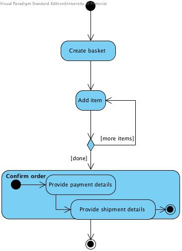
4 Figure 4: Model of a payment showing the use of decision and merge nodes Alternate flows Alternate flows are shown by using decision and merge nodes. Both these are shown as a diamond shape. If different activity edges leave such shape it is a decision node. If different activity edges meet at the shape, it is a merge node. Figure 4 shows a diagram with alternate flows. The guards on the action edges leaving the decision node on the left side of the figure specifies under what conditions each of these flows should execute. In this example there are three alternate flows depending on the kind of payment. Both cash and cheque payments requires some extra activity while the flow immediately proceed to the clear debt activity if a credit card payment is made. In the case of cheque payments the cheque is processed while cash payments require an update of the cash balance before proceeding to the clear debt action. It is important to note that only one of the alternate flows may execute at any time. Therefore, the guards should be mutually exclusive. In programming alternate flows represent conditional actions like in if and while statements Parallel flows Parallel flows are shown by using fork and join nodes. Both these are shown as a heavy vertical or horizontal line. If different activity edges leave such line it is a fork node. If different activity edges meet at the line, it is a join node. Figure 5 shows a diagram with parallel flows. When a fork is reached in the flow, all the activities to which the activity edges that leave the fork point, are executed at the same time using independent execution threads. This example models a shopping experience by a married couple. They both enter the shop and then proceed each on a separate mission. While the one person (probably the wife) picks up fruit, then meat and then milk, the other person move directly to the news stand to pick up a news paper. After both completed their respective actions, they join and proceed to the till. It is important to note that all the flows leaving a fork are executed in parallel. In programming new threads are spawned for each parallel flow Composite activities A composite activity is an activity that can itself be described in terms of an activity diagram. Sometimes composite activities are shown by drawing the diagram of its activi- 4
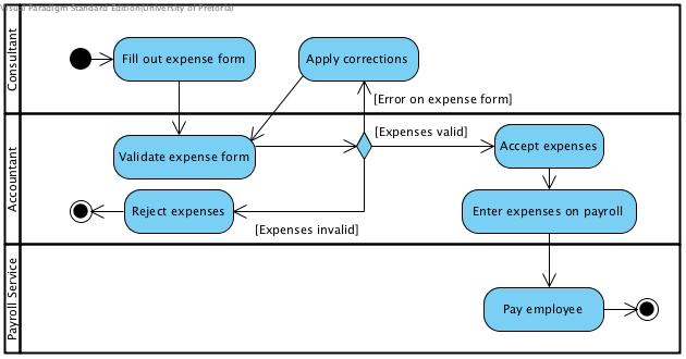
5 Figure 5: Fork and join nodes ties inside the action node as shown in the right hand diagram in Figure 6. A composite of which the sub-activities are not shown can be drawn using a rake symbol inside it as shown in the left hand diagram in Figure 6. Such sub-activity is called a called action. A called action is like a subroutine call in a program. Called actions are often used to eliminate the need to draw the same sub-activity diagram in more than one place Swimlanes Swimlanes are used to convey which class is responsible for a given activity. A swimlane is a vertical or horizontal zone in which the activities which are the responsibility of a certain class are grouped. Swimlanes are indicated using solid vertical or horizontal lines to indicate a border between two swimlanes and labeling the zones. The diagram in Figure 7 was adapted from [1]. It illustrates the use of swimlanes. In this diagram the consultant is responsible for filling in the expense form and correcting it if needed. The accountant is responsible for validating such form and taking the appropriate actions while the payroll service is responsible for paying the employer of the consultant Examples Finding and drinking a beverage The activity diagram in Figure 8 comes from the UML 1.0 documentation and was replicated from [2]. This diagram illustrates the interpretation of an activity diagram on a conceptual level. There parallel activities Put Coffee in Filter,Add Water to Reservoir and Get Cups may be interpreted to mean that these activities may be executed in any order or if possible at the same time by interleaving them. The synchronisation point indicated by the join node before Turn On Machine should be interpreted that the machine may only be turned on after both the putting the filter with coffee and putting water in the reservoir was completed. 5

6 Figure 6: Activities with sub-activities Figure 7: Processing an expense 6
7 Figure 8: Finding and drinking a beverage 7
8 Figure 9: An activity diagram containing a loop Implementing code for an activity diagram Activity diagrams can be translated into code. Each activity node is either a program statement or a function call. If it is a function call it can be indicated using the rake symbol. Decision nodes represent conditional statements like if or switch. If there is some transition from a later activity node back to a decision node, it represents a loop structure which can be implemented using a while-loop, a for-loop, or recursion. The activity diagram in Figure 9 contains a loop because the topmost decision node may be reached a number of times. The following code fragment is an implementation of the diagram in Figure 9 using a while-loop int value = 2 2 ; while ( value > 5) i f ( value < 10) value += 3 ; else value = 1 6 ; Activities based on age of the participant From an implementation-perspective the activities shown in an activity diagram represent methods in classes. To illustrate this we have created code to implement the activities 8
9 Figure 10: Activities for people of different age groups in the activity diagram in Figure 10 and came up with the following code: #include <iostream> #include <boost / thread. hpp> using namespace std ; using namespace boost ; void gobowling ( ) ; void bunjyjump ( ) ; void stayhome ( ) ; void study ( ) ; int main ( ) int age ; thread stayhomethread = thread ( stayhome ) ; thread studythread = thread ( study ) ; cout << Please e n t e r your age : ; c i n >> age ; i f ( age > 60) gobowling ( ) ; else i f ( age > 21) bunjyjump ( ) ; else 9
10 stayhomethread. j o i n ( ) ; studythread. j o i n ( ) ; cout << Actions while threads are running << endl ; stayhomethread. detach ( ) ; studythread. detach ( ) ; void gobowling ( ) cout << Enjoy the day playing bowls << endl ; void bunjyjump ( ) cout << Drive to the p r e c i p i c e, ; cout << attach the bunjy cord and jump!!!! << endl ; void stayhome ( ) cout << Stay Home << endl ; void study ( ) cout << Study << endl ; An article [4] that was written by the author of the Boost.Threads library will get you started on installing and using this library and writing multi-threaded applications using the C++ programming language 1. References [1] SW Ambler. Uml 2 activity diagramming guidelines. com/style/activitydiagram.htm, [Online; accessed ]. [2] Martin Fowler and Kendall Scott. UML Distilled: Applying the Standard Object Modeling Language. Addison-Wesley, Reading, Mass, In this module you must be able to understand code using threads. However, it will not be expected of you have to write such code yourself 10
11 [3] F. B. Gilbreth and L. M. Gilbreth. Process charts: first steps in finding the one best way to do work. Presented at the Annual Meeting of The American Society of Mechanical Engineers, New York, USA, [4] William E. Kempf. The boost.threads library [Online: Accessed 1 Sept 2011]. [5] James Martin and James J. Odell. Object-Oriented Analysis and Design. Prentice Hall Inc, Englewood Cliffs, NJ 07632, [6] James Lyle Peterson. Petri Net Theory and the Modeling of Systems. Prentice Hall Inc, Englewood Cliffs, NJ 07632,
Software Service Engineering
 Software Service Engineering Lecture 4: Unified Modeling Language Doctor Guangyu Gao Some contents and notes selected from Fowler, M. UML Distilled, 3rd edition. Addison-Wesley Unified Modeling Language
Chapter 10. Object-Oriented Analysis and Modeling Using the UML. McGraw-Hill/Irwin
 Chapter 10 Object-Oriented Analysis and Modeling Using the UML McGraw-Hill/Irwin Copyright 2007 by The McGraw-Hill Companies, Inc. All rights reserved. Objectives 10-2 Define object modeling and explain
Activity Diagram Written Date : September 02, 2016
 Written Date : September 02, 2016 s describe how activities are coordinated to provide a service which can be at different levels of abstraction. Typically, an event needs to be achieved by some operation,
The Dynamic Model. An Introduction to UML. Enterprise Architect. by Geoffrey Sparks. All material (c) Geoffrey Sparks
 Geoffrey Sparks") An Introduction to UML The Dynamic Model by Geoffrey Sparks All material (c) Geoffrey Sparks 2001 www.sparxsystems.com.au Geoffrey Sparks 2001 Page:1 Table of Contents THE DYNAMIC MODEL... 3 INTRODUCTION
An Introduction to UML The Dynamic Model by Geoffrey Sparks All material (c) Geoffrey Sparks 2001 www.sparxsystems.com.au Geoffrey Sparks 2001 Page:1 Table of Contents THE DYNAMIC MODEL... 3 INTRODUCTION
Practical UML : A Hands-On Introduction for Developers
 Borland.com Borland Developer Network Borland Support Center Borland University Worldwide Sites Login My Account Help Search Practical UML : A Hands-On Introduction for Developers - by Randy Miller Rating:
2.1 Introduction UML Preliminaries Class diagrams Modelling delegation... 4
 Department of Computer Science COS121 Lecture Notes Chapter 2- Memento design pattern Copyright c 2015 by Linda Marshall and Vreda Pieterse. All rights reserved. Contents 2.1 Introduction.................................
Practical UML - A Hands-On Introduction for Developers
 Practical UML - A Hands-On Introduction for Developers By: Randy Miller (http://gp.codegear.com/authors/edit/661.aspx) Abstract: This tutorial provides a quick introduction to the Unified Modeling Language
Introduction to Software Engineering. 5. Modeling Objects and Classes
 Introduction to Software Engineering 5. Modeling Objects and Classes Roadmap > UML Overview > Classes, attributes and operations > UML Lines and Arrows > Parameterized Classes, Interfaces and Utilities
APPENDIX M INTRODUCTION TO THE UML
 M INTRODUCTION TO THE UML This appendix, written only for those readers not familiar with the topic, provides a brief introduction, which cannot be considered as exhaustive, to the UML. The UML is a general-purpose
From Analysis to Design. LTOOD/OOAD Verified Software Systems
 From Analysis to Design 1 Use Cases: Notation Overview Actor Use case System X System boundary UCBase «extend» UCExt Actor A UCVar1 UCVar2 Extending case Generalization «include» Actor B UCIncl Included
Chapter 2 Entity-Relationship Data Modeling: Tools and Techniques. Fundamentals, Design, and Implementation, 9/e
 Chapter 2 Entity-Relationship Data Modeling: Tools and Techniques Fundamentals, Design, and Implementation, 9/e Three Schema Model ANSI/SPARC introduced the three schema model in 1975 It provides a framework
26.1 Introduction Programming Preliminaries... 2
 Department of Computer Science Tackling Design Patterns Chapter 27: Proxy Design Pattern Copyright c 2016 by Linda Marshall and Vreda Pieterse. All rights reserved. Contents 26.1 Introduction.................................
Interactions A link message
 Interactions An interaction is a behavior that is composed of a set of messages exchanged among a set of objects within a context to accomplish a purpose. A message specifies the communication between
Business Process Modeling. Version 25/10/2012
 Business Process Modeling Version 25/10/2012 Maurizio Morisio, Marco Torchiano, 2012, 2013 3 BP Aspects Process flow Process modeling UML Activity Diagrams BPMN Information Conceptual modeling UML Class
UNIT-4 Behavioral Diagrams
 UNIT-4 Behavioral Diagrams P. P. Mahale Behavioral Diagrams Use Case Diagram high-level behaviors of the system, user goals, external entities: actors Sequence Diagram focus on time ordering of messages
Process Modelling. Fault Tolerant Systems Research Group. Budapest University of Technology and Economics
 Process Modelling Budapest University of Technology and Economics Fault Tolerant Systems Research Group Budapest University of Technology and Economics Department of Measurement and Information Systems
Statecharts 1.- INTRODUCTION 1.- INTRODUCTION
 Statecharts INDEX 1.- Introduction 2.- When to use Statecharts 3.- Basic components 4.- Connectors and compound transitions Mª Ángeles Martínez Ibáñez University of Bergen Selected topics in programming
Introduction to Software Engineering. 6. Modeling Behaviour
 Introduction to Software Engineering 6. Modeling Behaviour Roadmap > Use Case Diagrams > Sequence Diagrams > Collaboration (Communication) Diagrams > Activity Diagrams > Statechart Diagrams Nested statecharts
Chapter 2 Entity-Relationship Data Modeling: Tools and Techniques. Fundamentals, Design, and Implementation, 9/e
 Chapter 2 Entity-Relationship Data Modeling: Tools and Techniques Fundamentals, Design, and Implementation, 9/e Three Schema Model ANSI/SPARC introduced the three schema model in 1975 It provides a framework
Activities Radovan Cervenka
 Unified Modeling Language Activities Radovan Cervenka Activity Model Specification of an algorithmic behavior. Used to represent control flow and object flow models. Executing activity (of on object) is
SOFTWARE DESIGN COSC 4353 / Dr. Raj Singh
 SOFTWARE DESIGN COSC 4353 / 6353 Dr. Raj Singh UML - History 2 The Unified Modeling Language (UML) is a general purpose modeling language designed to provide a standard way to visualize the design of a
L23.1 Introduction... 2
 Department of Computer Science COS121 Lecture Notes: L23 Adapter Design Pattern 23 & 26 September 2014 Copyright c 2014 by Linda Marshall and Vreda Pieterse. All rights reserved. Contents L23.1 Introduction.................................
Object Oriented Design. Program Design. Analysis Phase. Part 2. Analysis Design Implementation. Functional Specification
 Object Oriented Design Part 2 Analysis Design Implementation Program Design Analysis Phase Functional Specification Completely defines tasks to be solved Free from internal contradictions Readable both
Lesson 11. W.C.Udwela Department of Mathematics & Computer Science
 Lesson 11 INTRODUCING UML W.C.Udwela Department of Mathematics & Computer Science Why we model? Central part of all the activities We build model to Communicate Visualize and control Better understand
What is a Class Diagram? A diagram that shows a set of classes, interfaces, and collaborations and their relationships
 Class Diagram What is a Class Diagram? A diagram that shows a set of classes, interfaces, and collaborations and their relationships Why do we need Class Diagram? Focus on the conceptual and specification
What is a Class Diagram? Class Diagram. Why do we need Class Diagram? Class - Notation. Class - Semantic 04/11/51
 What is a Class Diagram? Class Diagram A diagram that shows a set of classes, interfaces, and collaborations and their relationships Why do we need Class Diagram? Focus on the conceptual and specification
UML- a Brief Look UML and the Process
 UML- a Brief Look UML grew out of great variety of ways Design and develop object-oriented models and designs By mid 1990s Number of credible approaches reduced to three Work further developed and refined
7. UML Sequence Diagrams Page 1 of 1
 7. UML Sequence Diagrams Page 1 of 1 Sequence Diagram in UML In the last article, we saw Activity diagrams, the notations to be used in Activity diagrams, their significance, and how to build an Activity
Software Engineering Prof.N.L.Sarda IIT Bombay. Lecture-11 Data Modelling- ER diagrams, Mapping to relational model (Part -II)
") Software Engineering Prof.N.L.Sarda IIT Bombay Lecture-11 Data Modelling- ER diagrams, Mapping to relational model (Part -II) We will continue our discussion on process modeling. In the previous lecture
Software Engineering Prof.N.L.Sarda IIT Bombay Lecture-11 Data Modelling- ER diagrams, Mapping to relational model (Part -II) We will continue our discussion on process modeling. In the previous lecture
Process Modelling. Fault Tolerant Systems Research Group. Budapest University of Technology and Economics
 Process Modelling Budapest University of Technology and Economics Fault Tolerant Systems Research Group Budapest University of Technology and Economics Department of Measurement and Information Systems
LECTURE 3: BUSINESS ARCHITECTURE ASPECTS: BUSINESS PROCESS MODELLING
 LECTURE 3: BUSINESS ARCHITECTURE ASPECTS: BUSINESS PROCESS MODELLING CA4101 Lecture Notes (Martin Crane 2017) 1 Historical View of BP Modelling Work Process Flow (early to mid 1900s) o Frank Gilbreth &
Meltem Özturan
 Meltem Özturan www.mis.boun.edu.tr/ozturan/samd 1 2 Modeling System Requirements Object Oriented Approach to Requirements OOA considers an IS as a set of objects that work together to carry out the function.
BASICS OF BPMN BASIC BPMN SUBSET OKAY, SO WHAT DO I REALLY NEED TO KNOW? CHAPTER 2
 MicroGuide.book Page 23 Friday, June 17, 2011 12:26 PM CHAPTER 2 BASICS OF BPMN In the introduction, we defined BPMN concepts as the key elements of a business process model. This chapter presents BPMN
Business Process Modeling. Version /10/2017
 Business Process Modeling Version 1.2.1-16/10/2017 Maurizio Morisio, Marco Torchiano, 2012-2017 3 BP Aspects Process flow Process modeling UML Activity Diagrams BPMN Information Conceptual modeling UML
Darshan Institute of Engineering & Technology for Diploma Studies
 REQUIREMENTS GATHERING AND ANALYSIS The analyst starts requirement gathering activity by collecting all information that could be useful to develop system. In practice it is very difficult to gather all
Unified Modeling Language (UML)
") 1 / 45 Unified Modeling Language (UML) Miaoqing Huang University of Arkansas 2 / 45 Outline 1 Introduction 2 Use Case Diagram 3 Class Diagram 4 Sequence Diagram 3 / 45 Outline 1 Introduction 2 Use Case
1 / 45 Unified Modeling Language (UML) Miaoqing Huang University of Arkansas 2 / 45 Outline 1 Introduction 2 Use Case Diagram 3 Class Diagram 4 Sequence Diagram 3 / 45 Outline 1 Introduction 2 Use Case
JOURNAL OF OBJECT TECHNOLOGY
 JOURNAL OF OBJECT TECHNOLOGY Online at http://www.jot.fm. Published by ETH Zurich, Chair of Software Engineering JOT, 2003 Vol. 2, No. 6, November-December 2003 UML 2 Activity and Action Models Part 3:
Introduction for using UML
 Introduction for using UML Edition 2, 2006 Mikael Åkerholm, Ivica Crnković, Goran Mustapić, Mikael Davidsson Mälardalen University, Västerås, Sweden, 2006 Abstract The purpose with this document is to
Control Statements: Part Pearson Education, Inc. All rights reserved.
 1 5 Control Statements: Part 2 5.2 Essentials of Counter-Controlled Repetition 2 Counter-controlled repetition requires: Control variable (loop counter) Initial value of the control variable Increment/decrement
Model Migration Case for TTC 2010
 Model Migration Case for TTC 2010 Louis M. Rose, Dimitrios S. Kolovos, Richard F. Paige, and Fiona A.C. Polack Department of Computer Science, University of York, UK. [louis,dkolovos,paige,fiona]@cs.york.ac.uk
Unified Modeling Language (UML) Class Diagram
 Class Diagram") 1 / 10 Unified Modeling Language (UML) Class Diagram Miaoqing Huang University of Arkansas Spring 2010 2 / 10 Outline 1 2 3 / 10 Class Diagram Class diagrams show the static structure of the classes that
1 / 10 Unified Modeling Language (UML) Class Diagram Miaoqing Huang University of Arkansas Spring 2010 2 / 10 Outline 1 2 3 / 10 Class Diagram Class diagrams show the static structure of the classes that
The sequence of steps to be performed in order to solve a problem by the computer is known as an algorithm.
 CHAPTER 1&2 OBJECTIVES After completing this chapter, you will be able to: Understand the basics and Advantages of an algorithm. Analysis various algorithms. Understand a flowchart. Steps involved in designing
MSc programme (induction week) Department of Informatics INTRODUCTION TO UML
 Department of Informatics INTRODUCTION TO UML") MSc programme (induction week) Department of Informatics INTRODUCTION TO UML Some of this material is based on Bernd Bruegge and Allen H. Dutoit (2009) Object-Oriented Software Engineering: Using UML,
MSc programme (induction week) Department of Informatics INTRODUCTION TO UML Some of this material is based on Bernd Bruegge and Allen H. Dutoit (2009) Object-Oriented Software Engineering: Using UML,
Software Engineering I (02161)
") Software Engineering I (02161) Week 2 Assoc. Prof. Hubert Baumeister DTU Compute Technical University of Denmark Spring 2017 Contents What are software requirements? Requirements Engineering Process Domain
Software Engineering I (02161) Week 2 Assoc. Prof. Hubert Baumeister DTU Compute Technical University of Denmark Spring 2017 Contents What are software requirements? Requirements Engineering Process Domain
Software Engineering
 Software Engineering A systematic approach to the analysis, design, implementation and maintenance of software. Software Development Method by Jan Pettersen Nytun, page 1 Software Engineering Methods Most
Tackling Design Patterns Chapter 3: Template Method design pattern and Public Inheritance. 3.1 Introduction... 2
 Department of Computer Science Tackling Design Patterns Chapter 3: Template Method design pattern and Public Inheritance Copyright c 2016 by Linda Marshall and Vreda Pieterse. All rights reserved. Contents
UML Modeling I. Instructor: Yongjie Zheng September 3, CS 490MT/5555 Software Methods and Tools
 UML Modeling I Instructor: Yongjie Zheng September 3, 2015 CS 490MT/5555 Software Methods and Tools Object-Oriented Design: Topics & Skills Rational Unified Process Unified Modeling Languages (UML) Provide
Deriving Model-to-Code Transformation Rules at the Meta- Model Level
 Deriving Model-to-Code Transformation Rules at the Meta- Model Level Lei Liu Emanuel S. Grant Department of Computer Science University of North Dakota liu@cs.und.edu grante@cs.und.edu Abstract: The Unified
CS 370 REVIEW: UML Diagrams D R. M I C H A E L J. R E A L E F A L L
 CS 370 REVIEW: UML Diagrams D R. M I C H A E L J. R E A L E F A L L 2 0 1 5 Introduction UML Unified Modeling Language Very well recognized specification for modeling architectures, use cases, etc. UML
25.1 Introduction Façade Design Pattern Identification Problem Structure Participants...
 Department of Computer Science Tackling Design Patterns Chapter 25: Façade Design Pattern Copyright c 2016 by Linda Marshall and Vreda Pieterse. All rights reserved. Contents 25.1 Introduction.................................
Lab Manual. Object Oriented Analysis And Design. TE(Computer) VI semester
 VI semester") Lab Manual Object Oriented Analysis And Design TE(Computer) VI semester Index Sr. No. Title of Programming Assignment Page No. 1 2 3 4 5 6 7 8 9 10 Study of Use Case Diagram Study of Activity Diagram Study
Lab Manual Object Oriented Analysis And Design TE(Computer) VI semester Index Sr. No. Title of Programming Assignment Page No. 1 2 3 4 5 6 7 8 9 10 Study of Use Case Diagram Study of Activity Diagram Study
CS 451 Software Engineering
 CS 451 Software Engineering Yuanfang Cai Room 104, University Crossings 215.895.0298 yfcai@cs.drexel.edu 1 Elaboration 2 Elaboration: Building the Analysis Model An analysis model provides a description
Software Development. Designing Software
 Software Development Designing Software Modules Modular programming is a software design technique that emphasizes separating the functionality of a program into independent, interchangeable modules, such
OO Techniques & UML Class Diagrams
 OO Techniques & UML Class Diagrams SE3A04 Tutorial Jason Jaskolka Department of Computing and Software Faculty of Engineering McMaster University Hamilton, Ontario, Canada jaskolj@mcmaster.ca October 17,
INTRODUCTION TO UNIFIED MODELING MODEL (UML) & DFD. Slides by: Shree Jaswal
 & DFD. Slides by: Shree Jaswal") INTRODUCTION TO UNIFIED MODELING MODEL (UML) & DFD Slides by: Shree Jaswal What is UML? 2 It is a standard graphical language for modeling object oriented software. It was developed in mid 90 s by collaborative
INTRODUCTION TO UNIFIED MODELING MODEL (UML) & DFD Slides by: Shree Jaswal What is UML? 2 It is a standard graphical language for modeling object oriented software. It was developed in mid 90 s by collaborative
Lecture 33 April 4, Unied Modelling Language. ECE155: Engineering Design with Embedded Systems Winter Patrick Lam version 1
 ECE155: Engineering Design with Embedded Systems Winter 2013 Lecture 33 April 4, 2013 Patrick Lam version 1 Unied Modelling Language The Unied Modelling Language (UML) is a language for specifying and
COMN 1.1 Reference. Contents. COMN 1.1 Reference 1. Revision 1.1, by Theodore S. Hills, Copyright
 COMN 1.1 Reference 1 COMN 1.1 Reference Revision 1.1, 2017-03-30 by Theodore S. Hills, thills@acm.org. Copyright 2015-2016 Contents 1 Introduction... 2 1.1 Release 1.1... 3 1.2 Release 1.0... 3 1.3 Release
Today s Topic. Lecture 5. What is UML? Why Use UML. UML Diagrams. Introduction to UML. What is UML Why use UML? UML Diagrams
 Today s Topic Lecture 5 Introduction to UML What is UML Why use UML? UML Static Use case, Class, Object Deployment, Component (Physical ) Dynamic Sequence, Collaboration (Interaction ) Activity, State
Łabiak G., Miczulski P. (IIE, UZ, Zielona Góra, Poland)
") UML STATECHARTS AND PETRI NETS MODEL COMPARIS FOR SYSTEM LEVEL MODELLING Łabiak G., Miczulski P. (IIE, UZ, Zielona Góra, Poland) The system level modelling can be carried out with using some miscellaneous
UML STATECHARTS AND PETRI NETS MODEL COMPARIS FOR SYSTEM LEVEL MODELLING Łabiak G., Miczulski P. (IIE, UZ, Zielona Góra, Poland) The system level modelling can be carried out with using some miscellaneous
Name. Classes and Objects 1. We re going to develop a class to help out Café Below is the definition for a class called
 Name CPTR246 Spring '17 (100 total points) Exam 1 Classes and Objects 1. We re going to develop a class to help out Café 1812. Below is the definition for a class called Beverage. The public and private
SEEM4570 System Design and Implementation Lecture 11 UML
 SEEM4570 System Design and Implementation Lecture 11 UML Introduction In the previous lecture, we talked about software development life cycle in a conceptual level E.g. we need to write documents, diagrams,
Topics. Kinds of UML models. Use case modeling. Actors. Actor. Assignment of reqs to actors and use cases
 MACIASZEK, L.A. (2005): Requirements Analysis and System Design, 2 nd ed. Addison Wesley, Harlow England, 504p. ISBN 0 32 20464 6 Chapter 3.2 Objects and Object Modeling Fundamentals of object modeling
UML Fundamental. OutLine. NetFusion Tech. Co., Ltd. Jack Lee. Use-case diagram Class diagram Sequence diagram
 UML Fundamental NetFusion Tech. Co., Ltd. Jack Lee 2008/4/7 1 Use-case diagram Class diagram Sequence diagram OutLine Communication diagram State machine Activity diagram 2 1 What is UML? Unified Modeling
Vidyalankar. T.Y. Diploma : Sem. VI [IF/CM] Object Oriented Modeling and Design Prelim Question Paper Solution
![Vidyalankar. T.Y. Diploma : Sem. VI [IF/CM] Object Oriented Modeling and Design Prelim Question Paper Solution](/thumbs/86/94007497.jpg "Vidyalankar. T.Y. Diploma : Sem. VI [IF/CM] Object Oriented Modeling and Design Prelim Question Paper Solution") T.Y. Diploma : Sem. VI [IF/CM] Object Oriented Modeling and Design Prelim Question Paper Solution Q.1(a) Attempt any THREE of the following [12] Q.1(a) (i) What is modeling? Also state its four features.
T.Y. Diploma : Sem. VI [IF/CM] Object Oriented Modeling and Design Prelim Question Paper Solution Q.1(a) Attempt any THREE of the following [12] Q.1(a) (i) What is modeling? Also state its four features.
Fundamentals of Health Workflow Process Analysis and Redesign
 Fundamentals of Health Workflow Process Analysis and Redesign Unit 10.3d Process Mapping Gane-Sarson Notation Slide 1 Welcome to the Gane-Sarson Notation for Data Flow Diagrams Subunit. This is the third
ACS-3913 Ron McFadyen 1. UML Notation for Class diagrams Object diagrams
 ACS-3913 Ron McFadyen 1 UML Notation for Class diagrams Object diagrams Class Diagram ACS-3913 Ron McFadyen 2 A class diagram begins as a conceptual or analysis class model and evolves to a design class
BASICS OF UML (PART-2)
") BASICS OF UML (PART-2) 1 USE CASE DIAGRAMS 2 USE CASE DIAGRAMS Use Case Model: a view of a system that emphasizes the behavior as it appears to outside users. A use case model partitions system functionality
BASICS OF UML (PART-2) 1 USE CASE DIAGRAMS 2 USE CASE DIAGRAMS Use Case Model: a view of a system that emphasizes the behavior as it appears to outside users. A use case model partitions system functionality
OO Using UML: Dynamic Models
 OO Using UML: Dynamic Models Defining how the objects behave Overview The object model describes the structure of the system (objects, attributes, and operations) The dynamic model describes how the objects
MAHARASHTRA STATE BOARD OF TECHNICAL EDUCATION (Autonomous) (ISO/IEC Certified)
 (ISO/IEC Certified)") Subject Code: 17630 Model Answer Page No: 1 /32 Important Instructions to examiners: 1) The answers should be examined by keywords and not as word-to-word as given in the model answer scheme. 2) The model
Subject Code: 17630 Model Answer Page No: 1 /32 Important Instructions to examiners: 1) The answers should be examined by keywords and not as word-to-word as given in the model answer scheme. 2) The model
LABORATORY 1 REVISION
 UTCN Computer Science Department Software Design 2012/2013 LABORATORY 1 REVISION ================================================================== I. UML Revision This section focuses on reviewing the
The Unified Modeling Language (UML)
") The Unified Modeling Language (UML) A Very Distilled Introduction to The Unified Modeling Language (UML). A quick introduction to UML is given. Thereafter, the surface of class and activity diagrams and
The Unified Modeling Language (UML) A Very Distilled Introduction to The Unified Modeling Language (UML). A quick introduction to UML is given. Thereafter, the surface of class and activity diagrams and
SEEM4570 System Design and Implementation. Lecture 10 UML
 SEEM4570 System Design and Implementation Lecture 10 UML Introduction In the previous lecture, we talked about software development life cycle in a conceptual level E.g. we need to write documents, diagrams,
Specifying Precise Use Cases with Use Case Charts
 Specifying Precise Use Cases with Use Case Charts Jon Whittle Dept of Information & Software Engineering George Mason University 4400 University Drive Fairfax, VA 22030 jwhittle@ise.gmu.edu Abstract. Use
9 Structured design. Overview of structured design. Transaction analysis. Transform analysis. System integration
 9 Structured design Overview of structured design Transaction analysis Transform analysis System integration 9.3 Structured design After SSA has produced a set of DFDs, there are three steps to turn the
Interaction Modelling: Use Cases
 Interaction Modelling: Use Cases Fabrizio Maria Maggi Institute of Computer Science (these slides are derived from the book Object-oriented modeling and design with UML ) Interaction Modelling: INPUT 1
On to Iteration 3, and Activity Diagrams CSSE 574: Session 6, Part 1
 On to Iteration 3, and Activity Diagrams CSSE 574: Session 6, Part 1 Steve Chenoweth Phone: Office (812) 877-8974 Cell (937) 657-3885 Email: chenowet@rose-hulman.edu On to Iteration 3: NextGen POS Failover
Introduction to UML Diagrams
 Bern University of Applied Sciences H T I Bienne Department I Basic Programming Introduction to UML Diagrams J.-P. Dubois Content State Machine Diagrams Class Diagrams Object Diagrams Sequence Diagrams
Chapter 13. Recursion. Copyright 2016 Pearson, Inc. All rights reserved.
 Chapter 13 Recursion Copyright 2016 Pearson, Inc. All rights reserved. Learning Objectives Recursive void Functions Tracing recursive calls Infinite recursion, overflows Recursive Functions that Return
Fundamentals of Health Workflow Process Analysis and Redesign
 Fundamentals of Health Workflow Process Analysis and Redesign This material Comp0_Unit3d was developed by Duke University, funded by the Department of Health and Human Services, Office of the National
How and Why to Use the Unified Modeling Language. among software components, architectural-based
 This article addresses the Unified Modeling Language and its purpose, constructs, and application to defense software development applications. The Unified Modeling Language (UML) is a notation that can
Control Statements. Musa M. Ameen Computer Engineering Dept.
 2 Control Statements Musa M. Ameen Computer Engineering Dept. 1 OBJECTIVES In this chapter you will learn: To use basic problem-solving techniques. To develop algorithms through the process of topdown,
Activity Nets: A UML profile for modeling workflow and business processes
 Activity Nets: A UML profile for modeling workflow and business processes Author: Gregor v. Bochmann, SITE, University of Ottawa (August 27, 2000) 1. Introduction 1.1. Purpose of this document Workflow
Course "Softwaretechnik" Book Chapter 2 Modeling with UML
 Course "Softwaretechnik" Book Chapter 2 Modeling with UML Lutz Prechelt, Bernd Bruegge, Allen H. Dutoit Freie Universität Berlin, Institut für Informatik http://www.inf.fu-berlin.de/inst/ag-se/ Modeling,
CMPT 354 Database Systems I
 CMPT 354 Database Systems I Chapter 2 Entity Relationship Data Modeling Data models A data model is the specifications for designing data organization in a system. Specify database schema using a data
Engineering Design w/embedded Systems
 1 / 40 Engineering Design w/embedded Systems Lecture 33 UML Patrick Lam University of Waterloo April 4, 2013 2 / 40 What is UML? Unified Modelling Language (UML): specify and document architecture of large
UNIT 5 - UML STATE DIAGRAMS AND MODELING
 UNIT 5 - UML STATE DIAGRAMS AND MODELING UML state diagrams and modeling - Operation contracts- Mapping design to code UML deployment and component diagrams UML state diagrams: State diagrams are used
MSO Analysis & UML. Hans Philippi (based on the course slides of Wouter Swierstra) August 24, Analysis & UML 1 / 56
 August 24, Analysis & UML 1 / 56") MSO Analysis & UML Hans Philippi (based on the course slides of Wouter Swierstra) August 24, 2018 Analysis & UML 1 / 56 Recap: Last lectures How can I manage the process of constructing complex software?
MSO Analysis & UML Hans Philippi (based on the course slides of Wouter Swierstra) August 24, 2018 Analysis & UML 1 / 56 Recap: Last lectures How can I manage the process of constructing complex software?
What s Next. INF 117 Project in Software Engineering. Lecture Notes -Spring Quarter, Michele Rousseau Set 6 System Architecture, UML
 What s Next INF 117 Project in Software Engineering Lecture Notes -Spring Quarter, 2008 Michele Rousseau Set 6 System Architecture, UML Set 6 2 Announcements kreqs should be complete Except minor changes
Ali Khan < Project Name > Design Document. Version 1.0. Group Id: S1. Supervisor Name: Sir.
 < Project Name > Design Document Version 1.0 Group Id: S1. Supervisor Name: Sir. Revision History Date Version Description Author Table of Contents 1. Introduction of Design Document 2. Entity Relationship
What is a Model? Copyright hebley & Associates
 Modeling Overview... as we know, there are known knowns; there are things we know we know. We also know there are known unknowns; that is to say we know there are some things we do not know. But there
Model Migration Case for TTC 2010
 Model Migration Case for TTC 2010 Louis M. Rose, Dimitrios S. Kolovos, Richard F. Paige, and Fiona A.C. Polack Department of Computer Science, University of York, UK. [louis,dkolovos,paige,fiona]@cs.york.ac.uk
MAHARASHTRA STATE BOARD OF TECHNICAL EDUCATION (Autonomous) (ISO/IEC Certified) MODEL ANSWER
 (ISO/IEC Certified) MODEL ANSWER") Important Instructions to examiners: 1) The answers should be examined by key words and not as word-to-word as given in the model answer scheme. 2) The model answer and the answer written by candidate
Important Instructions to examiners: 1) The answers should be examined by key words and not as word-to-word as given in the model answer scheme. 2) The model answer and the answer written by candidate
UML REFERENCE SHEETS. 2013, 2014 Michael Marking; all rights reserved, including moral rights. Web site:
 UML Reference Sheets 2013, 2014 Michael Marking; all rights reserved, including moral rights. Web site: http://www.tatanka.com/ Revision Information This document was last revised 2014.03.02. The current
Object-Oriented Systems Analysis and Design Using UML
 10 Object-Oriented Systems Analysis and Design Using UML Systems Analysis and Design, 8e Kendall & Kendall Copyright 2011 Pearson Education, Inc. Publishing as Prentice Hall Learning Objectives Understand
An Evaluation of ERwin
 An Evaluation of ERwin by David C. Hay ERwin is arguably the most popular CASE tool on the market today. In the view of your author, this is unfortunate, because it has shortcomings that prevent users
Credit where Credit is Due. Lecture 4: Fundamentals of Object Technology. Goals for this Lecture. Real-World Objects
 Lecture 4: Fundamentals of Object Technology Kenneth M. Anderson Object-Oriented Analysis and Design CSCI 6448 - Spring Semester, 2003 Credit where Credit is Due Some material presented in this lecture
Models are used for several purposes. We believe that some of the most important are:
 Course: Objekt orientated programming, extending course Supervisor: Authors: Marc Mikael Karlsson, Sandberg Fredrik Fahlman and Martin Mileros Mälardalens Högskola, spring-2000 UML Contents 1. Introduction...
5 th Grade Hinojosa Math Vocabulary Words
 Topic 1 Word Definition Picture value The place of a digit in a number tells the value digit The symbols of 0,1,2,3,4,5,6,7,8, and 9 used to write numbers standard form A number written with one digit
ANALYZING PROCESS MODELS USING GRAPH REDUCTION TECHNIQUES
 NLYZING PROCESS MODELS USING GRPH REDUCTION TECHNIQUES WSIM SDIQ ND MRI E. ORLOWSK Distributed Systems Technology Centre Department of Computer Science & Electrical Engineering The University of Queensland,
Introducing the UML Eng. Mohammed T. Abo Alroos
 Introducing the UML Eng. Mohammed T. Abo Alroos Islamic University of Gaza Introduction to the UML: The UML stands for Unified Modeling Language. It was released in 1997 as a method to diagram software