Business Process Modeling. Version /10/2017
|
|
|
- Alberta Butler
- 5 years ago
- Views:
Transcription


1 Business Process Modeling Version /10/2017 Maurizio Morisio, Marco Torchiano,
2 3 BP Aspects Process flow Process modeling UML Activity Diagrams BPMN Information Conceptual modeling UML Class diagrams (Entity-Relationships) Interaction Functional modeling Use cases
3 UML Unified Modeling Language Standardized by OMG Several diagrams Class diagrams Activity diagrams Use Case diagrams (Sequence diagrams) (Statecharts) Conceptual modeling Process modeling Functional modeling
4 Objectives Describe, as precisely as possible, a process (or workflow) Communicate, document, analyze, validate the workflow Implement (execute) it Only formal notations allow this step
5 Issues Formal notations Executable But model can be very complex for high level of detail Semiformal Not executable But can be starting point for high level analysis
6 Notations Formal UML Activity Diagrams BPMN BPEL Semi formal IDEF0 Data Flow Diagrams
7 Process Modeling UML ACTIVITY DIAGRAM
8 Goal Capture Activities Rules Responsibilities
9 Activity Diagram Extension of Statechart Diagram used to represent temporal sequence of activities and data flow Used to represent workflow process, or the inner service logic of an algorithm or function, process Parallel process representation and synchronization (fork join) 10

10 Action Represents a task or operation that can be performed by either a human or automatically by the IS
11 Terminal nodes Initial node Represents the starting point of the process execution Create a new token Final node Indicate that the processing has completed Destroy all tokens
12 Semantics A token flows through the diagram The token is created at the initial node The token comply with the process rules The token is eventually destroyed at end node
13 Semantics When a token arrives at an action The action is enabled: can be performed The information systems informs the intended user she can start the action No time is defined for starting the activity It starts when the user wishes No duration is defined for the activity It takes as much time as the user needs The token can leave the action as soon as the activity is completed.
14 Basic patterns Sequence Parallel split Synchronization Exclusive choice Merge Multiple choice
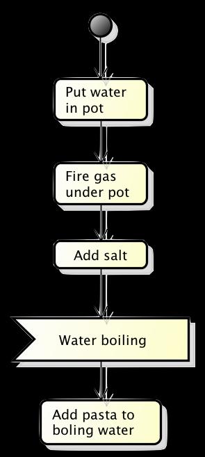
15 Sequence An action in a process is enabled after the completion of a preceding action Aka serialization It is the essential building block Can be used to build a series of consecutive actions that take place in turn one after the other
16 Sequence The arc determines the order of execution

17 Sequence - Semantics A token flows through the diagram Following the arcs Stopping at actions Performing actions
18 Parallel split From a certain point on a thread diverges into several parallel threads that can be executed concurrently Aka fork, AND-split Represents Actions taking place at the same time (concurrently) Actions being performed without any specific order Possibly even serialized
19 Parallel split fork

20 Parallel split- Semantics When the token reaches the fork it is duplicated as many times as there are outgoing arcs
21 Synchronization Define a synchronization point or rendezvous After a group of actions have been executed in parallel Before proceeding with further activities all the previous one must be complete
22 Synchronization join

23 Synchronization- Semantics When one token per incoming arc has reached the join, they are merged into a single token
24 Exclusive choice A diversion of the thread into several alternative paths Exactly one alternative is picked up and followed during execution Aka conditional routing, decision Each path is characterized by a guard Represent a condition that, when true, enable the execution of the corresponding path

25 Exclusive choice
26 Exclusive choice Semantics The token follows exactly one of the outgoing arcs
27 Merge The convergence of two or more threads into a single one Any incoming thread activates the outgoing path Aka join No synchronization is performed
28 Exclusive choice


29 Merge Semantics The token getting to the merge proceeds to the only outgoing arc

30 Multiple choice When several paths are available it is possible to chose one or more of them If no path is chosen, we have an abnormal stop to the flow
31 Example
32 Structured processes Each action has exactly one input flow and one output flow Fork and Join must be coupled Decision and Merge must be coupled
33 Swimlanes Actions can be responsibility of different actors or roles A swimlane groups together all the activities of a specific actor Assigning responsibilities is not always required Typically it represents a refinement step
34 Swimlanes - Example
35 Swimlanes - Example
36 Swimlanes - Example
37 Prescriptive vs. Descriptive Initial goal: understand the procedure currently in place Descriptive Next goal: provide guidance for defining IS-supported procedures Prescriptive Advice: avoid unnecessary constraints
38 Additional features EVENTS, OBJECTS
39 Signals and Events Using an event that origins outside the process as a guard to proceed with the execution of a process Temporal signal Signal acceptance Signal sending


40 Temporal signal

41 Signal acceptance


42 Signal sending

43 Signals Example
44 Object nodes Indicate that an object node will be available at a specific point in the activity Produced by an action Consumed by an action The object is an instance of a class defined in the conceptual model Or possibly a base type

45 Object nodes Grade = 30
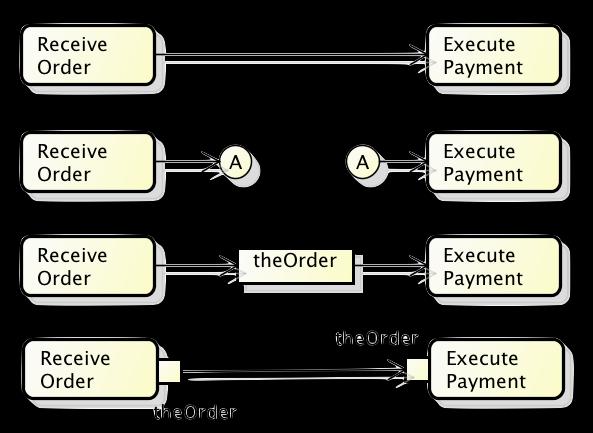
46 Arcs
47 ADVANCED PATTERNS
48 Complex structures Complex activities Cycles / loops Arbitrary cycles Implicit termination Multiple choice

49 Complex action Represent a complex (sub-)process a single action Call behavior The contents of the complex action can be represented in an additional diagram
50 Structured Loop One or more activities are repeated until a specific condition become true Realized by means of decision and merge nodes First a merge node Then a condition
51 Loop - Repeat do { read_item(); pick_item(); } while( more_items );

52 Loop - semantics
{ read_item(); pick_item(); }")
53 Loop - While while( more_items ){ read_item(); pick_item(); }
54 Arbitrary cycles Loop that is unstructured or not block structured. That is, the looping segment of the process may allow more than one entry or exit point. Important for the visualization of valid, but complex, looping situations in a single diagram
55 Arbitrary Cycle pattern is a mechanism for allowing sections of a process to be repeated it is a l pattern Arbitrary allows looping that is cycles unstructured or not block structured. That is, the looping segmen rocess may allow more than one entry or exit point. This pattern is important for the visualizatio lid, but complex, looping situations in a single diagram. Notations that allow only block structur s would not be able to display the entire process in a single diagram or process level or would dis te the behavior in a non-intuitive manner. ness Process Diagram possible to create an Arbitrary Cycle pattern within a Business Process Diagram by connecting S ce Flow to upstream activities (see Figure 26). Figure 26: WP #11: Arbitrary Cycles Business Process Diagram 12
56 Implicit termination A specific path of a process can be concluded without other parallel paths be required to end as well. The normal case require the whole process to end when any end node is reached.

57 Implicit termination - semantics Only one path is terminated
58 Explicit termination - semantics ALL path are terminated. i.e. the whole process is terminated
59 Structured Discriminator Convergence of two or more branches such that the first activation of an incoming branch results in the subsequent activity being triggered while subsequent activations of remaining incoming branches are ignored.
60 2014/10/2 m0 Structured Discriminator Discriminator Pr evious action act Discriminator Discriminator Alternative 1 Alternative 2 Next action
61 Deferred choice A divergence point in a process where one of several possible branches should be activated. The actual decision on which branch is activated is made by the environment and is deferred to the latest possible moment.

62 erred Choice 2014 Deferred choice t Deferred Choice Choice Pr evious Action act Choice Choice [signal 1] [signal 2] < < signal receip t> > Signal 1 < < signal receip t> > Signal 2 Op tion 1 Op tion 2
63 Free Tools Argo UML Astah community Star UML (win) Graphical editors Some support to translate to java No support to execute activity diagrams
64 References OMG UML web site M. Fowler, UML Distilled, Addison-Wesley N. Russell et al. WORKFLOW CONTROL-FLOW PATTERNS A Revised View PM pdf N.Russel et al. On the Suitability of UML 2.0 Activity Diagrams for Business Process Modelling MLEvalAPCCM.pdf Workflow Patterns web site
65 IDEF
66 IDEF Integrated Computer-aided Manufacturing Definition Approach of choice in the 1990s (have been around for over 25 years) Only one compliant with Federal Information Processing Standards (FIPS) FIPS Publication
67 IDEF IDEF refers to a group of methods, each of which fulfills a specific purpose IDEFØ, for example, is used to model an organization's functions IDEF1x is used for DB modeling 68
68 IDEFØ Box and arrow" graphics function as a box interfaces to or from the function as arrows entering or leaving the box Context diagram (main) Constraint diagrams (sub) Decomposition 69
69 IDEFØ - Example Controls Inventory Customer Inputs Customer Order Operate Warehouse Purchase Orders Shipment Outputs Order Confirmation, Invoice Materials Management Carrier Mechanisms (Resources) 70
70 IDEFØ - Decomposition 71
71 DFD
72 DFD Data Flow Diagram Yourdon and Coad Gane and Sarson 73
73 DFD - Decomposition Initially a context diagram is drawn, which is a simple representation of the entire system under investigation This is followed by a level 1 diagram, which identifies major business processes at a high level These processes can then be analyzed further with level 2 diagrams And so on 74
74 DFD - Objects Process A process is a unit of work that operates on the data Data flow A data flow is a named flow of data through a system of processes Data store A data store is a logical repository of data External entity An external agent is a source or destination of data 75
75 DFD Example Process Customer Account info 2 Counter Enquiries Deposit & Withdrawals External entity Data flow Account info D2 Account details Banking process maintaing customer accounts Data store D persistent digital storage T temporary digital storage 76
76 DFD Example II External entity Data flow Process Data flow Data store 77
77 DFD - Rules Data flows are allowed between different external entities processes and external entities processes and data stores Data flows are not allowed between external entities and data stores one data store and another 78
Business Process Modeling. Version 25/10/2012
 Business Process Modeling Version 25/10/2012 Maurizio Morisio, Marco Torchiano, 2012, 2013 3 BP Aspects Process flow Process modeling UML Activity Diagrams BPMN Information Conceptual modeling UML Class
HCM Modeling Elements. Creating a better understanding of the process model standards used within the MHR-BPS Process Modeling initiative.
 HCM Modeling Elements Creating a better understanding of the process model standards used within the MHR-BPS Process Modeling initiative. HCMS Modeling Element Process This presentation will: o o o o Present
Data and Process Modelling
 Data and Process Modelling 8a. BPMN - Basic Modelling Marco Montali KRDB Research Centre for Knowledge and Data Faculty of Computer Science Free University of Bozen-Bolzano A.Y. 2014/2015 Marco Montali
UNIT-4 Behavioral Diagrams
 UNIT-4 Behavioral Diagrams P. P. Mahale Behavioral Diagrams Use Case Diagram high-level behaviors of the system, user goals, external entities: actors Sequence Diagram focus on time ordering of messages
White Paper Workflow Patterns and BPMN
 White Paper Workflow Patterns and BPMN WP0121 December 2013 In general, a pattern describes a solution for a recurring problem. Patterns are commonly used in architecture as a formal way of documenting
LAB-03 BPMN Resource Perspective and Events
 Lab for the course on Process and Service Modeling and Analysis LAB-03 BPMN Resource Perspective and Events Lecturer: Andrea MARRELLA Objectives of this lecture Recap: Pools, Swimlanes and Message Flows
Appendix D: Mapping BPMN to BPD Profile
 Appendix D: Mapping BPMN to BPD Profile Members of bpmi.org and the OMG are interested in the unification of the UML 2.0 and BPMN notation for the support of the business user. This draft mapping is in
Activity Diagram Written Date : September 02, 2016
 Written Date : September 02, 2016 s describe how activities are coordinated to provide a service which can be at different levels of abstraction. Typically, an event needs to be achieved by some operation,
JOURNAL OF OBJECT TECHNOLOGY
 JOURNAL OF OBJECT TECHNOLOGY Online at http://www.jot.fm. Published by ETH Zurich, Chair of Software Engineering JOT, 2003 Vol. 2, No. 6, November-December 2003 UML 2 Activity and Action Models Part 3:
Business Process Management (BPM) Lecture 3: Advanced BPMN
 Lecture 3: Advanced BPMN") MTAT.03.231 Business Process Management (BPM) (for Masters of IT) Lecture 3: Advanced BPMN Marlon Dumas marlon.dumas ät ut. ee BPMN Main Elements - Recap Connections Swimlanes Message Flow Flow Objects
MTAT.03.231 Business Process Management (BPM) (for Masters of IT) Lecture 3: Advanced BPMN Marlon Dumas marlon.dumas ät ut. ee BPMN Main Elements - Recap Connections Swimlanes Message Flow Flow Objects
Workflow : Patterns and Specifications
 Workflow : Patterns and Specifications Seminar Presentation by Ahana Pradhan Under the guidance of Prof. Rushikesh K. Joshi Department of Computer Science and Engineering Indian Institute of Technology,
An Introduction to Business Process Modeling using Data Flow Diagrams
 An Introduction to Business Process Modeling using Data Flow Diagrams BSAD 141 Dave Novak BDIS: 2.2 (61-77) Lecture Overview Systems and Business processes Business process models Data Flow Diagrams (DFDs)
Activities Radovan Cervenka
 Unified Modeling Language Activities Radovan Cervenka Activity Model Specification of an algorithmic behavior. Used to represent control flow and object flow models. Executing activity (of on object) is
State Machine Diagrams
 State Machine Diagrams Introduction A state machine diagram, models the dynamic aspects of the system by showing the flow of control from state to state for a particular class. 2 Introduction Whereas an
Requirements Engineering
 Requirements Engineering Semi-Formal Specification: Structural Functional Requirements Structured Analysis Data Flow Diagrams SADT IDEF0 1 Back to the past GO/AO OO SA (DT) DFD SADT IDEF (Back to the future)
Interactions A link message
 Interactions An interaction is a behavior that is composed of a set of messages exchanged among a set of objects within a context to accomplish a purpose. A message specifies the communication between
Meltem Özturan
 Meltem Özturan www.mis.boun.edu.tr/ozturan/samd 1 2 Modeling System Requirements Object Oriented Approach to Requirements OOA considers an IS as a set of objects that work together to carry out the function.
Introduction to Software Engineering. 6. Modeling Behaviour
 Introduction to Software Engineering 6. Modeling Behaviour Roadmap > Use Case Diagrams > Sequence Diagrams > Collaboration (Communication) Diagrams > Activity Diagrams > Statechart Diagrams Nested statecharts
Darshan Institute of Engineering & Technology for Diploma Studies
 REQUIREMENTS GATHERING AND ANALYSIS The analyst starts requirement gathering activity by collecting all information that could be useful to develop system. In practice it is very difficult to gather all
Business Process Model and Notation (BPMN)
") Business Process Model and Notation (BPMN) Daniel Brookshier, Distinguished Fellow, No Magic Inc. 1 BPMN Introduction n BPMN 2.0 is an international standard for business process modeling. n Developed
Business Process Model and Notation (BPMN) Daniel Brookshier, Distinguished Fellow, No Magic Inc. 1 BPMN Introduction n BPMN 2.0 is an international standard for business process modeling. n Developed
Business Process Modelling
 CS565 - Business Process & Workflow Management Systems Business Process Modelling CS 565 - Lecture 2 20/2/17 1 Business Process Lifecycle Enactment: Operation Monitoring Maintenance Evaluation: Process
Business Object Process Modeling overview of Workflow patterns
 Business Object Process Modeling overview of Workflow patterns Version of the document: 0.9 Author: Ľudovít Scholtz Date: 17.4.2013-18.4.2013
Open Work of Two-Hemisphere Model Transformation Definition into UML Class Diagram in the Context of MDA
 Open Work of Two-Hemisphere Model Transformation Definition into UML Class Diagram in the Context of MDA Oksana Nikiforova and Natalja Pavlova Department of Applied Computer Science, Riga Technical University,
Object-Oriented and Classical Software Engineering
 Slide 16.1 Object-Oriented and Classical Software Engineering Seventh Edition, WCB/McGraw-Hill, 2007 Stephen R. Schach srs@vuse.vanderbilt.edu CHAPTER 16 Slide 16.2 MORE ON UML 1 Chapter Overview Slide
Software Service Engineering
 Software Service Engineering Lecture 4: Unified Modeling Language Doctor Guangyu Gao Some contents and notes selected from Fowler, M. UML Distilled, 3rd edition. Addison-Wesley Unified Modeling Language
INTRODUCTION TO UNIFIED MODELING MODEL (UML) & DFD. Slides by: Shree Jaswal
 & DFD. Slides by: Shree Jaswal") INTRODUCTION TO UNIFIED MODELING MODEL (UML) & DFD Slides by: Shree Jaswal What is UML? 2 It is a standard graphical language for modeling object oriented software. It was developed in mid 90 s by collaborative
INTRODUCTION TO UNIFIED MODELING MODEL (UML) & DFD Slides by: Shree Jaswal What is UML? 2 It is a standard graphical language for modeling object oriented software. It was developed in mid 90 s by collaborative
Lesson 11. W.C.Udwela Department of Mathematics & Computer Science
 Lesson 11 INTRODUCING UML W.C.Udwela Department of Mathematics & Computer Science Why we model? Central part of all the activities We build model to Communicate Visualize and control Better understand
For 100% Result Oriented IGNOU Coaching and Project Training Call CPD TM : ,
 Course Code : MCS-032 Course Title : Object Oriented Analysis and Design Assignment Number : MCA (3)/032/Assign/2014-15 Assignment Marks : 100 Weightage : 25% Last Dates for Submission : 15th October,
Activity Nets: A UML profile for modeling workflow and business processes
 Activity Nets: A UML profile for modeling workflow and business processes Author: Gregor v. Bochmann, SITE, University of Ottawa (August 27, 2000) 1. Introduction 1.1. Purpose of this document Workflow
Business-Driven Software Engineering Lecture 5 Business Process Model and Notation
 Business-Driven Software Engineering Lecture 5 Business Process Model and Notation Jochen Küster jku@zurich.ibm.com Agenda BPMN Introduction BPMN Overview BPMN Advanced Concepts Introduction to Syntax
Chapter 1 Introduction
 Chapter 1 Introduction We hardly need to point out the importance of business process modelling and of respective automation in this place (see, e.g. [39, 45, 58, 110, 141]). Also the advantages and shortcomings
Course "Softwaretechnik" Book Chapter 2 Modeling with UML
 Course "Softwaretechnik" Book Chapter 2 Modeling with UML Lutz Prechelt, Bernd Bruegge, Allen H. Dutoit Freie Universität Berlin, Institut für Informatik http://www.inf.fu-berlin.de/inst/ag-se/ Modeling,
UML BUSINESS MODELING PROFILE
 UML BUSINESS MODELING PROFILE Audris Kalnins, Janis Barzdins, Edgars Celms 1. INTRODUCTION At the time of writing this paper, UML 2.0 has reached its near final status, no significant changes are expected.
Extending BPEL with transitions that can loop
 Extending BPEL with transitions that can loop ActiveVOS linksaretransitions BPEL Extension AN ACTIVE ENDPOINTS PAPER AUTHOR: DR MICHAEL ROWLEY 2009 Active Endpoints Inc. ActiveVOS is a trademark of Active
The Unified Modeling Language (UML)
") The Unified Modeling Language (UML) A Very Distilled Introduction to The Unified Modeling Language (UML). A quick introduction to UML is given. Thereafter, the surface of class and activity diagrams and
The Unified Modeling Language (UML) A Very Distilled Introduction to The Unified Modeling Language (UML). A quick introduction to UML is given. Thereafter, the surface of class and activity diagrams and
6/20/2018 CS5386 SOFTWARE DESIGN & ARCHITECTURE LECTURE 5: ARCHITECTURAL VIEWS C&C STYLES. Outline for Today. Architecture views C&C Views
 1 CS5386 SOFTWARE DESIGN & ARCHITECTURE LECTURE 5: ARCHITECTURAL VIEWS C&C STYLES Outline for Today 2 Architecture views C&C Views 1 Components and Connectors (C&C) Styles 3 Elements Relations Properties
APPENDIX M INTRODUCTION TO THE UML
 M INTRODUCTION TO THE UML This appendix, written only for those readers not familiar with the topic, provides a brief introduction, which cannot be considered as exhaustive, to the UML. The UML is a general-purpose
Modeling with Activity Diagram
 Modeling with Activity Diagram The following elements are available in a activity diagram. ActionState SubactivityState InitialState FinalState Synchronization Decision Flow Final Object Flow Signal Accept
JOURNAL OF OBJECT TECHNOLOGY
 JOURNAL OF OBJECT TECHNOLOGY Online at http://www.jot.fm. Published by ETH Zurich, Chair of Software Engineering JOT, 2004 Vol. 3, No. 7, July-August 2004 UML 2 Activity and Action Models Part 5: Partitions
Faster Or-join Enactment for BPMN 2.0
 Faster Or-join Enactment for BPMN 2.0 Hagen Völzer, IBM Research Zurich Joint work with Beat Gfeller and Gunnar Wilmsmann Contribution: BPMN Diagram Enactment Or-join Tokens define the control state Execution
On to Iteration 3, and Activity Diagrams CSSE 574: Session 6, Part 1
 On to Iteration 3, and Activity Diagrams CSSE 574: Session 6, Part 1 Steve Chenoweth Phone: Office (812) 877-8974 Cell (937) 657-3885 Email: chenowet@rose-hulman.edu On to Iteration 3: NextGen POS Failover
Process Modelling. Fault Tolerant Systems Research Group. Budapest University of Technology and Economics
 Process Modelling Budapest University of Technology and Economics Fault Tolerant Systems Research Group Budapest University of Technology and Economics Department of Measurement and Information Systems
What is Business Process Management
 usiness gility! Who we are Vision Software has excelled for more than fourteen years through its creativity, quality and dedication to client service. We focus on collaborative software development and
Sequence Diagrams. Massimo Felici. Massimo Felici Sequence Diagrams c
 Sequence Diagrams Massimo Felici What are Sequence Diagrams? Sequence Diagrams are interaction diagrams that detail how operations are carried out Interaction diagrams model important runtime interactions
A UML 2 Profile for Variability Models and their Dependency to Business Processes
 A UML 2 Profile for Variability Models and their Dependency to Business Processes Birgit Korherr and Beate List Women s Postgraduate College for Internet Technologies Institute of Software Technology and
CS350 Lecture 2 Requirements Engineering. Doo-Hwan Bae
 CS350 Lecture 2 Requirements Engineering Doo-Hwan Bae bae@se.kaist.ac.kr Contents Overview of Requirements Engineering OO Analysis: Domain modeling, Use-case, sequence, class Structured Analysis: Dataflow
Ingegneria del Software Corso di Laurea in Informatica per il Management
 Ingegneria del Software Corso di Laurea in Informatica per il Management UML: State machine diagram Davide Rossi Dipartimento di Informatica Università di Bologna State machine A behavioral state machine
MAHARASHTRA STATE BOARD OF TECHNICAL EDUCATION (Autonomous) (ISO/IEC Certified)
 (ISO/IEC Certified)") Subject Code: 17630 Model Answer Page No: 1 /32 Important Instructions to examiners: 1) The answers should be examined by keywords and not as word-to-word as given in the model answer scheme. 2) The model
Subject Code: 17630 Model Answer Page No: 1 /32 Important Instructions to examiners: 1) The answers should be examined by keywords and not as word-to-word as given in the model answer scheme. 2) The model
Process Modelling. Fault Tolerant Systems Research Group. Budapest University of Technology and Economics
 Process Modelling Budapest University of Technology and Economics Fault Tolerant Systems Research Group Budapest University of Technology and Economics Department of Measurement and Information Systems
Practical UML : A Hands-On Introduction for Developers
 Borland.com Borland Developer Network Borland Support Center Borland University Worldwide Sites Login My Account Help Search Practical UML : A Hands-On Introduction for Developers - by Randy Miller Rating:
16.1 Introduction... 2
 Department of Computer Science Tackling Design Patterns Chapter 16: UML Activity Diagrams Copyright c 2016 by Linda Marshall and Vreda Pieterse. All rights reserved. Contents 16.1 Introduction.................................
Unified Modeling Language I.
 Unified Modeling Language I. Software engineering Szoftvertechnológia Dr. Balázs Simon BME, IIT Outline Software engineering Modeling Unified Modeling Language (UML) UML Diagrams: Use Case Diagram Activity
Object-Oriented Software Engineering Practical Software Development using UML and Java. Chapter 8: Modelling Interactions and Behaviour
 Object-Oriented Software Engineering Practical Software Development using UML and Java Chapter 8: Modelling Interactions and Behaviour 8.1 Interaction Diagrams Interaction diagrams are used to model the
Object Oriented Design. Program Design. Analysis Phase. Part 2. Analysis Design Implementation. Functional Specification
 Object Oriented Design Part 2 Analysis Design Implementation Program Design Analysis Phase Functional Specification Completely defines tasks to be solved Free from internal contradictions Readable both
3. Business Process Diagram Concepts
 PN Working Draft 3. usiness Process Diagram oncepts This section provides a summary of the PN graphical objects and their relationships. ore details on the concepts will be provided in usiness Process
UML Diagrams MagicDraw UML Diagrams
 In software development, the diagram is the equivalent of a blueprint. To meet the various needs of many parties, we often need several different blueprints of the same system. Furthermore, every system
CreditInfo = [Jane, 16000] AcceptCredit. Fig Process instance where request approval activity is not required
![CreditInfo = [Jane, 16000] AcceptCredit. Fig Process instance where request approval activity is not required](/thumbs/72/66874566.jpg "CreditInfo = [Jane, 16000] AcceptCredit. Fig Process instance where request approval activity is not required") 4.7 Business Process Modeling Notation 205 RiskFactor = low CreditInfo = [Miller, 15000] Accept Credit CreditInfo = [Miller, 15000] CreditInfo = [Jane, 16000] CreditInfo = [Jane, 16000] RiskFactor = low
4.7 Business Process Modeling Notation 205 RiskFactor = low CreditInfo = [Miller, 15000] Accept Credit CreditInfo = [Miller, 15000] CreditInfo = [Jane, 16000] CreditInfo = [Jane, 16000] RiskFactor = low
Practical UML - A Hands-On Introduction for Developers
 Practical UML - A Hands-On Introduction for Developers By: Randy Miller (http://gp.codegear.com/authors/edit/661.aspx) Abstract: This tutorial provides a quick introduction to the Unified Modeling Language
Unified Modeling Language 2
 Unified Modeling Language 2 State machines 109 History and predecessors 1950 s: Finite State Machines Huffmann, Mealy, Moore 1987: Harel Statecharts conditions hierarchical (and/or) states history states
COSC 3351 Software Design. An Introduction to UML (I)
") COSC 3351 Software Design An Introduction to UML (I) This lecture contains material from: http://wps.prenhall.com/esm_pfleeger_softengtp_2 http://sunset.usc.edu/classes/cs577a_2000/lectures/05/ec-05.ppt
COSC 3351 Software Design An Introduction to UML (I) This lecture contains material from: http://wps.prenhall.com/esm_pfleeger_softengtp_2 http://sunset.usc.edu/classes/cs577a_2000/lectures/05/ec-05.ppt
MSc programme (induction week) Department of Informatics INTRODUCTION TO UML
 Department of Informatics INTRODUCTION TO UML") MSc programme (induction week) Department of Informatics INTRODUCTION TO UML Some of this material is based on Bernd Bruegge and Allen H. Dutoit (2009) Object-Oriented Software Engineering: Using UML,
MSc programme (induction week) Department of Informatics INTRODUCTION TO UML Some of this material is based on Bernd Bruegge and Allen H. Dutoit (2009) Object-Oriented Software Engineering: Using UML,
3rd Lecture Languages for information modeling
 3rd Lecture Languages for information modeling Agenda Languages for information modeling UML UML basic concepts Modeling by UML diagrams CASE tools: concepts, features and objectives CASE toolset architecture
06. Analysis Modeling
 06. Analysis Modeling Division of Computer Science, College of Computing Hanyang University ERICA Campus 1 st Semester 2017 Overview of Analysis Modeling 1 Requirement Analysis 2 Analysis Modeling Approaches
Review of Basic Software Design Concepts. Fethi Rabhi SENG 2021
 Review of Basic Software Design Concepts Fethi Rabhi SENG 2021 1 Topics The development process Planning Designing Implementing 2 1. The development process How to organise activities related to the creation,
Software Engineering I (02161)
") Software Engineering I (02161) Week 2 Assoc. Prof. Hubert Baumeister DTU Compute Technical University of Denmark Spring 2017 Contents What are software requirements? Requirements Engineering Process Domain
Software Engineering I (02161) Week 2 Assoc. Prof. Hubert Baumeister DTU Compute Technical University of Denmark Spring 2017 Contents What are software requirements? Requirements Engineering Process Domain
Business Processes Definition Metamodel Concepts and Overview
 Business Processes Definition Metamodel Concepts and Overview Joachim H. Frank Tracy A. Gardner Simon K. Johnston Stephen A. White Sridhar Iyengar all of IBM Software Group version 2004-05-03 (Draft) Abstract
Traditional Approaches to Modeling
 Traditional Approaches to Modeling Timeliness, Performance and How They Relate to Modeling, Architecture and Design Mark S. Gerhardt Chief Architect Pittsburgh, PA 15213 Levels of Real Time Performance
Enterprise Architect. User Guide Series. UML Models. Author: Sparx Systems. Date: 30/06/2017. Version: 1.0 CREATED WITH
 Enterprise Architect User Guide Series UML Models Author: Sparx Systems Date: 30/06/2017 Version: 1.0 CREATED WITH Table of Contents UML Models UML Diagrams UML Structural Models Class Diagram Composite
visualstate Reference Guide
 COPYRIGHT NOTICE Copyright 2000 2014 IAR Systems AB. No part of this document may be reproduced without the prior written consent of IAR Systems. The software described in this document is furnished under
Joint Entity Resolution
 Joint Entity Resolution Steven Euijong Whang, Hector Garcia-Molina Computer Science Department, Stanford University 353 Serra Mall, Stanford, CA 94305, USA {swhang, hector}@cs.stanford.edu No Institute
Chapter 3 Research Method
 Chapter 3 Research Method 3.1 A Ontology-Based Method As we mention in section 2.3.6, we need a common approach to build up our ontologies for different B2B standards. In this chapter, we present a ontology-based
9 Patterns of Process Modeling
 9 Patterns of Process Modeling WIL M.P. VAN DER AALST 1;2, ARTHUR H.M. TER HOFSTEDE 2, MARLON DUMAS 2 1 Eindhoven University of Technology, The Netherlands 2 Queensland University of Technology, Australia
A Pattern-based Analysis of Clinical Computer- Interpretable Guideline Modeling Languages
 Page 1 of 45 pages A Pattern-based Analysis of Clinical Computer- Interpretable Guideline Modeling Languages Nataliya Mulyar 1 MSc, Wil M.P. van der Aalst 1 PhD, Mor Peleg 2 PhD Affiliations of the authors:
Security Requirements Modeling Tool
 Security Requirements Modeling Tool SecBPMN2 Elements Reference Guide (rev 1.0) For STS-Tool Version 2.1 Contact: ststool@disi.unitn.it Table of contents BPMN 2.0... 5 Connections... 5 Association... 5
Object-Oriented Software Engineering Practical Software Development using UML and Java
 Object-Oriented Software Engineering Practical Software Development using UML and Java Chapter 5: Modelling with Classes Lecture 5 5.1 What is UML? The Unified Modelling Language is a standard graphical
Oral Questions. Unit-1 Concepts. Oral Question/Assignment/Gate Question with Answer
 Unit-1 Concepts Oral Question/Assignment/Gate Question with Answer The Meta-Object Facility (MOF) is an Object Management Group (OMG) standard for model-driven engineering Object Management Group (OMG)
SE Assignment III. 1. List and explain primitive symbols used for constructing DFDs. Illustrate the use of these symbols with the help of an example.
 SE Assignment III 1. List and explain primitive symbols used for constructing DFDs. Illustrate the use of these symbols with the help of an example. There are essentially 5 different types of symbols used
Chapter 10. Object-Oriented Analysis and Modeling Using the UML. McGraw-Hill/Irwin
 Chapter 10 Object-Oriented Analysis and Modeling Using the UML McGraw-Hill/Irwin Copyright 2007 by The McGraw-Hill Companies, Inc. All rights reserved. Objectives 10-2 Define object modeling and explain
Exercise Unit 2: Modeling Paradigms - RT-UML. UML: The Unified Modeling Language. Statecharts. RT-UML in AnyLogic
 Exercise Unit 2: Modeling Paradigms - RT-UML UML: The Unified Modeling Language Statecharts RT-UML in AnyLogic Simulation and Modeling I Modeling with RT-UML 1 RT-UML: UML Unified Modeling Language a mix
Business Processes Modelling MPB (6 cfu, 295AA)
") Business Processes Modelling MPB (6 cfu, 295AA) Roberto Bruni http://www.di.unipi.it/~bruni 13 - Workflow nets!1 Object We study some special kind of Petri nets, that are suitable models of workflows Ch.4.4
Business Processes Modelling MPB (6 cfu, 295AA) Roberto Bruni http://www.di.unipi.it/~bruni 13 - Workflow nets!1 Object We study some special kind of Petri nets, that are suitable models of workflows Ch.4.4
We move from a general information system to a Computer Based Information System
 Introduction to Information Systems: In this section of the course we start to think of the computer as just being a component in a system which may contain one or many computers linked together. An Information
Chapter : Analysis Modeling
 Chapter : Analysis Modeling Requirements Analysis Requirements analysis Specifies software s operational characteristics Indicates software's interface with other system elements Establishes constraints
Lab 16: Visio Introduction
 Lab 16: Visio Introduction () CONTENTS 1 Visio- Introduction to DFD Data Flow Diagraming... 2 1.1 In-Lab... 3 1.1.1 In-Lab Materials... 3 1.1.2 In-Lab Instructions... 3 2 Getting started: Let s decompose
SEEM4570 System Design and Implementation. Lecture 10 UML
 SEEM4570 System Design and Implementation Lecture 10 UML Introduction In the previous lecture, we talked about software development life cycle in a conceptual level E.g. we need to write documents, diagrams,
IDEF3 Process Modeling
 IDEF3 Process Modeling What is a Process Model? Simply pyp put, the Process Model is the way that work is divided in a value delivery system. James B. Swartz A representation of a process and its related
What is a Class Diagram? A diagram that shows a set of classes, interfaces, and collaborations and their relationships
 Class Diagram What is a Class Diagram? A diagram that shows a set of classes, interfaces, and collaborations and their relationships Why do we need Class Diagram? Focus on the conceptual and specification
What is a Class Diagram? Class Diagram. Why do we need Class Diagram? Class - Notation. Class - Semantic 04/11/51
 What is a Class Diagram? Class Diagram A diagram that shows a set of classes, interfaces, and collaborations and their relationships Why do we need Class Diagram? Focus on the conceptual and specification
Diagnostic Information for Control-Flow Analysis of Workflow Graphs (aka Free-Choice Workflow Nets)
") Diagnostic Information for Control-Flow Analysis of Workflow Graphs (aka Free-Choice Workflow Nets) Cédric Favre(1,2), Hagen Völzer(1), Peter Müller(2) (1) IBM Research - Zurich (2) ETH Zurich 1 Outline
Diagnostic Information for Control-Flow Analysis of Workflow Graphs (aka Free-Choice Workflow Nets) Cédric Favre(1,2), Hagen Völzer(1), Peter Müller(2) (1) IBM Research - Zurich (2) ETH Zurich 1 Outline
UNIT I. 3. Write a short notes on process view of 4+1 architecture. 4. Why is object-oriented approach superior to procedural approach?
 Department: Information Technology Questions Bank Class: B.E. (I.T) Prof. Bhujbal Dnyaneshwar K. Subject: Object Oriented Modeling & Design dnyanesh.bhujbal11@gmail.com ------------------------------------------------------------------------------------------------------------
Chapter 12. UML and Patterns. Copyright 2008 Pearson Addison-Wesley. All rights reserved
 Chapter 12 UML and Patterns Copyright 2008 Pearson Addison-Wesley. All rights reserved Introduction to UML and Patterns UML and patterns are two software design tools that can be used within the context
In This Lecture You Will Learn: Specifying Control. Statechart. Event, State and Transition
 In This Lecture You Will Learn: Specifying Control Lecture 11 How to identify requirements for control in an application How to model object life cycles using statecharts How to develop statechart diagrams
TIBCO BusinessEvents Business Process Orchestration Developers Guide
 TIBCO BusinessEvents Business Process Orchestration Developers Guide Software Release 1.1.0 February 2014 Two-Second Advantage Important Information SOME TIBCO SOFTWARE EMBEDS OR BUNDLES OTHER TIBCO SOFTWARE.
OBJECT ORIENTED DESIGN with the Unified Process. Use Case Realization
 OBJECT ORIENTED DESIGN with the Unified Process Use Case Realization Objectives Explain the purpose and objectives of objectoriented design Develop design class diagrams Develop detailed sequence diagrams
The Dynamic Model. An Introduction to UML. Enterprise Architect. by Geoffrey Sparks. All material (c) Geoffrey Sparks
 Geoffrey Sparks") An Introduction to UML The Dynamic Model by Geoffrey Sparks All material (c) Geoffrey Sparks 2001 www.sparxsystems.com.au Geoffrey Sparks 2001 Page:1 Table of Contents THE DYNAMIC MODEL... 3 INTRODUCTION
An Introduction to UML The Dynamic Model by Geoffrey Sparks All material (c) Geoffrey Sparks 2001 www.sparxsystems.com.au Geoffrey Sparks 2001 Page:1 Table of Contents THE DYNAMIC MODEL... 3 INTRODUCTION
From Analysis to Design. LTOOD/OOAD Verified Software Systems
 From Analysis to Design 1 Use Cases: Notation Overview Actor Use case System X System boundary UCBase «extend» UCExt Actor A UCVar1 UCVar2 Extending case Generalization «include» Actor B UCIncl Included
Formal Verification of Business Process Configuration within a Cloud Environment
 Formal Verification of Business Process Configuration within a Cloud Environment Presented by Souha Boubaker Telecom SudParis, UMR 5157 Samovar, Paris-Saclay University, France ENIT, UR-OASIS, University
Thirty one Problems in the Semantics of UML 1.3 Dynamics
 Thirty one Problems in the Semantics of UML 1.3 Dynamics G. Reggio R.J. Wieringa September 14, 1999 1 Introduction In this discussion paper we list a number of problems we found with the current dynamic
3. Business Process Diagrams
 BPMN Working Draft 3. Business Process Diagrams This section provides a summary of the BPMN graphical objects and their relationships. More details on the concepts will be provided in Business Process
Tool Support for Design Inspection: Automatic Generation of Questions
 Tool Support for Design Inspection: Automatic Generation of Questions Tim Heyer Department of Computer and Information Science, Linköping University, S-581 83 Linköping, Email: Tim.Heyer@ida.liu.se Contents
Monitoring BPMN-Processes with Rules in a Distributed Environment
 Monitoring BPMN-Processes with Rules in a Distributed Environment Lothar Hotz 1, Stephanie von Riegen 1, Lars Braubach 2, Alexander Pokahr 2, and Torsten Schwinghammer 3 1 HITeC e.v. c/o Fachbereich Informatik,