|
|
|
- Phillip Morrison
- 5 years ago
- Views:
Transcription
1 Overview RFSv4.3 is a RF module providing easy and flexible wireless data transmission between devices. It is based on AVR Atmega8 with serial output which can be interfaced directly to PC. Features 2.4 GHz Carrier Frequency RS232 UART interface with variable baud rate Input supply voltage: 5V to 12V 255 possible Channels frequencies (0 to 255) Programmable Device Address (255 per channel) Default mode is 0 and baudrate is Easy-to-Use AT command: Set working mode, Serial Baud Rate, etc. Compact Size, Out of Box: Plug and Play Supported Baud Rate 9600,19200, Two easily configurable modes: Data mode and Command node. Page 1
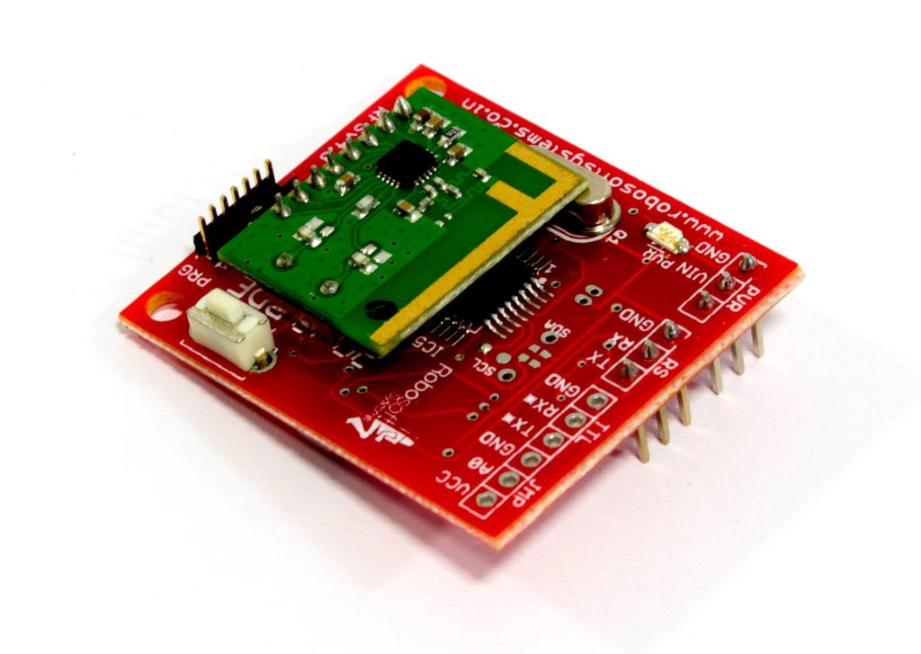
2 Pin Configuration Page 2
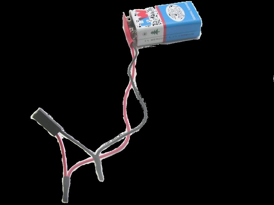
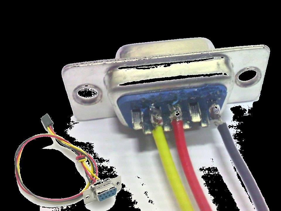


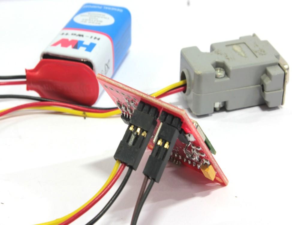
3 [RF Communication Release] 2012 Connecting the RF Module Step 1 Step 3 Page 3 Step 2 Step 4
4 Note [RF Communication Release] 2012 Configuring the RF Module Version The firmware version can be check by issuing ATFV command. Out of the box When powered on, RF module will send ok through serial port at 9600 baud. The default operation mode is Transceiver and the default sender and receiver address is 0. If you have two RF module, any data sent to RF_A from serial port the same data will be received by RF_B and displayed on the serial port. AT Commands The configuration of the RF module can be modified using AT commands. At startup the RF module is in data mode. To submit AT commands, the RF module must be switched to command mode by sending three plus signs ( +++ ) on serial port software. When the RF module receives the ( +++ ) on the serial port it will respond with: ok, starting command mode. The RFBee is now in command mode until switched back to data mode (using ATO0 see below) or power reset. AT Format: AT + Comand(ASCII) + parameters (optional, character)+<cr> Where <CR> is Carriage Return which has binary value 13 (0x0D in Hex). Page 4
5 [RF Communication Release] 2012 Example: Go to command mode, the RF module will return ok, starting cmd mode ATBD1<CR> - Set Uart Baudrate of the RF module to 19200, returns ok on success and otherwise error. ATBD<CR> - Get UART Baudrate of the RF module, returns 1 and ok on success and otherwise error. ATO0<CR> - Switch to data mode from command mode, the RFBee will return ok and any data send afterwards will be transmitted again. For ex: In flash magic go to Tools Terminal select com port option -set new lines to CR ( carriage return) Command Parameter AC 0-2 MA DA Adressing Page 5 Specification Address Check: determines whether the RF module checks the incoming packet address against its own address or not. If broadcast is enabled both its own address and the broadcast 0 address will be considered valid. 0:No address check 1:Address check, no broadcast 2:Address check and broadcast My Address: set the RF module s own Destination Address: set address of the receiver Default Typ e 0 r/w 0 r/w 0 r/w
6 Config: select wireless transmission data rate 0: 500kbaud RF CF 0-3 1: 250kbaud 2: 10kbaud 0 r/w BD 0-2 3: 2.4kbaud Baud Rate: Set Uart Baud rate of the RF. 0: 9600bps 1: 19200bps 2: 38400bps 0 r/w TH 0-32 Threshold: Set threshold in bytes that will trigger RF to start transmission. 1 r/w Serial 0: Payload only. OF 0-3 1: source, dest, payload 2: payload len, source, dest, payload, rssi, lqi 0 r/w 3: same as 2, but all except for payload as decimal and separated by comma's Page 6
7 MD 0-2 Mode: Set working mode of the RF. 0:transceive 1:transmit only 0 r/w Mode 2:receive only O 0 Online: return to data mode w CI Miscellaneous RS - To select device channel ID. Restore: restore the configuration to default settings. 0 r/w - w Output format : Using ATOF it is possible to change the output format of data packets received. ATOF set to 0: Payload ATOF set to 1: Source address (1 byte) Destination address (1 byte) Payload Page 7
8 ATOF set to 2: Payload length (1 byte) Source Address (1 byte) Destination address (1byte) Payload RSSI (1 byte) LQI (1 byte) ATOF set to 3: As ATOF2, but now all byte values (except Payload) displayed as decimal and all fields separated by comma s. RSSI: Received Signal Strength Indicator. One byte signed data, unit dbm. LQI: Link quality indicator. One byte data, see CC2500 datasheet for details. Broadcasting : When every RF module has it s a unique address assigned (e.g. 1,2,3 and 4 if you have 4 RF module) there are two ways to let all RF modules receive the same packets: 1. Set ATAC to 0: this will disable address checking and all RF modules will receive all packets sent. Downside of this is that any private communication between e.g. 2 and 3 will always show up at 1 and Set ATAC to 2: this will enable address checking including broadcasts. This will enable private communication between RF modules (e.g. packets between 2 and 3 will not show up at 1 and 4). The RF module sending the broadcast must set the destination address to 0. Packets with destination address 0 will be received by all four RF modules. Page 8


9 Receive window of RF Module No. 1 Transmit window of RF Module No. 1 Fig 1(a )RF Module No. 1 Receive window of RF Module No. 2 Transmit window of RF Module No. 2 Test Case 1: PC to PC Wireless communication using CC2500 based RF modules. Configure the modules using AT commands: By default address check is disabled and data transmitted by one module will be received by all other modules. Once the 2 modules have been connected to 2 different PC s and are powered on with the terminal initialized on both of them, the connection may be tested. Any data transmitted from one PC will appear on the other PC, character by character. Check fig.1 (a) and 1(b) for input and output on two different PCs. Fig 1(b ) RF Module No. 2 Page 9
10 Test Case 2: BOT to BOT Wireless communication using CC2500 based RF modules The example shows the implementation of data transfer using the modules. The following code will allow LED1 of BOT1 to be synchronized with LED1 of BOT2. Initial Settings for Test Case 2: With default settings, address check is disabled. so, data transmitted by one RF will be received by all. For communication between 2 specific modules enable address check using AT commands : For ex: with ATAC =1 Configure the source and destination address using AT commands: ATMA = my address, ATDA = destination address, ATCI = channel ID. RF Module No. 1: RF Module No. 2: 1) ATMA 1, 2) ATDA 2 3) Channel id 0, 3) baud rate 9600(ATBD=0) 1) ATMA 2, 2) ATDA 1 3) Channel id 0, 3) baud rate 9600(ATBD=0) Below is the code required to be programmed in both the bots: The code part labeled as bot1 will be the master. For the master the bot2 code must be commented. The code part labeled as bot2 is for slave. For the slave the bot1 code must be commented. In the below code, the Bot2 section (slave bot) is shown as commented. Make sure to use proper commenting for each case, in order for the code to work correctly. Page 10
11 #include <avr/io.h> // header file defining I/o operation #define F_CPU // 8MHZ #define USART_BAUDRATE 9600 // SERIAL 9600 baud #define BAUD_PRESCALE (((F_CPU / (USART_BAUDRATE * 16UL))) - 1) // baud rate formula #include <util/delay.h> // header file defining delay int main (void) // main code begins { DDRB = 0xff; // PORT B as output DDRD = 0xfc; // PORT D PIN 3-7 as output. PIN 2 is input for switch UCSRB = (1 << RXEN) (1 << TXEN); // Enable Rx & Tx of USART UCSRC = (1 << URSEL) (1 << UCSZ0) (1 << UCSZ1); // 8bit, 1 Stop bit, no parity UBRRL = BAUD_PRESCALE; // setting baud 9600 baud UBRRH = (BAUD_PRESCALE >> 8); unsigned char a=1; unsigned char b; // Character Variable for Rx packet. while(1) // loop forever Page 11
12 { /* //BOT1 code //Tx Code if (a == '0') a='1'; else a='0'; UDR = a; // Add next byte to be transmitted to the UDR buffer while ((UCSRA & (1 << UDRE)) == 0); // Loop until UDR buffer is ready to receive // next byte to be transmitted. while ((UCSRA & (1 << RXC)) == 0); // Loop until UDR buffer is receiving RECEIVE data. b = UDR; // Read byte by byte from the Received Data Packet into the variable if (b == '1') //check for Actual data from received Packet to be = (ASCII - '1') { PORTB = 0x01; // led1 on led2 off if true if a[2] == 0x52 } else PORTB = 0x00; Page 12
13 _delay_ms(1000); */ /* //BOT2 code. //Rx Code while ((UCSRA & (1 << RXC)) == 0); // Loop until UDR buffer is receiving RECEIVE data. b = UDR; // Read byte by byte from the Received Data Packet into the variable if (b == '1') //check for Actual data from received Packet to be = 0x52 (ASCII - R) { PORTB = 0x01; // led1 on led2 off if true if a[2] == 0x52 } else PORTB = 0x00; if (a == '0') a='1'; else a='0'; UDR = a; // Add next byte to be transmitted to the UDR buffer Page 13
14 while((ucsra & (1 << UDRE)) == 0); // Loop until UDR buffer is ready to receive // next byte to be transmitted. _delay_ms(1000); */ } // While loop closed. return(0); // syntax never reached } Note 1:- Mount the RF modules, one each on the mounting space provided on the two bots. Switch on the two bots. Note 2:- To trace the communication simultaneously on Terminal, open terminal on separate Computers one for each bot. Create a connection with following settings: 1) Port Com1, 2) Baud rate 9600, 3) Flow Control None, 4) Data 8bit, 5) Parity None, 6) Stop Bit 1bit Make use of the 3 wire serial interface provided on the board besides the MCU to watch the signals. You should get a stream of toggling 0 s and 1 s in terminal. Page 14
 Features 2.4 GHz Carrier Frequency RS232 UART interface with variable baud rate Input supply voltage: 5V to 12V 255 possible Channels frequencies (0 to 255) Programmable Device Address (255 per channel)
How to use RFpro in Packet Mode
 How to use RFpro in Packet Mode Jumper Setting Priority Jumper J1 à Configuration Mode Jumper à Higher Priority Jumper J2 à Packet Mode Jumper à Lower Priority When both the jumpers are connected, by default,
Using the USART Serial Communications
 Using the USART Serial Communications Tutorial (c) Dean Camera, 2007. dean_camera@hotmail.com This tutorial will focus on setting up the serial USART on the AVR platform. Although other hardware AVR interfaces
UART: Universal Asynchronous Receiver & Transmitter
 ECE3411 Fall 2015 Lecture 2a. UART: Universal Asynchronous Receiver & Transmitter Marten van Dijk, Syed Kamran Haider Department of Electrical & Computer Engineering University of Connecticut Email: {vandijk,
Using printf with an AVR
 Using printf with an AVR Based on : http://efundies.com/avr/avr_printf.htm Required Functions You should keep all of the functions that you need from the previous guide: usart_init() usart_getchar() usart_purchar()
International Journal of Emerging Technology and Advanced Engineering Website: (ISSN , Volume 2, Issue 5, May 2012)
") Enhanced Wireless Personal Area Network based Real Time motion(human) data Collection for advanced control room in Power Plants using ZigBee Transceiver Module Rajesh Singh 1, Madhu Sharma 2, Vivek Kaundal
Enhanced Wireless Personal Area Network based Real Time motion(human) data Collection for advanced control room in Power Plants using ZigBee Transceiver Module Rajesh Singh 1, Madhu Sharma 2, Vivek Kaundal
Serial Communications
 1 Serial Interfaces 2 Embedded systems often use a serial interface to communicate with other devices. Serial Communications Serial implies that it sends or receives one bit at a time. Serial Interfaces
WEATHER STATION WITH SERIAL COMMUNICATION
 WEATHER STATION WITH SERIAL COMMUNICATION Written by: Wenbo Ye, Xiao Qu, Carl-Wilhelm Igelström FACULTY OF ENGINEERING, LTH Digital and Analogue Projects EITF11 Contents Introduction... 2 Requirements...
USART Register Description
 USART Register Description USART I/O Data Register UDR RXB[7:0] TXB[7:0] Read/Write R/W R/W R/W R/W R/W R/W R/W R/W Initial Value 0 0 0 0 0 0 0 0 UDR (Read) UDR (Write) The USART Transmit Data Buer Register
Robosoft Systems in association with JNCE presents. Swarm Robotics
 Robosoft Systems in association with JNCE presents Swarm Robotics What is a Robot Wall-E Asimo ABB Superior Moti ABB FlexPicker What is Swarm Robotics RoboCup ~ 07 Lets Prepare for the Robotics Age The
19.1. Unit 19. Serial Communications
 9. Unit 9 Serial Communications 9.2 Serial Interfaces Embedded systems often use a serial interface to communicate with other devices. Serial implies that it sends or receives one bit at a time. µc Device
CSCE 236 Embedded Systems, Fall 2017 Homework 5
 CSCE 236 Embedded Systems, Fall 2017 Homework 5 Started: Tuesday, November 7th, 2017 Due: Friday, November 17th, 2017 (5pm) Instructions: This homework is an individual assignment, collaboration is not
Innovati s Bluetooth 100M Universal Wireless Bluetooth Module
 Innovati s Bluetooth 100M Universal Wireless Bluetooth Module Bluetooth 100M module is a simple to use Bluetooth module, command control through a simple UART Tx and Rx which are connected to other Bluetooth
[WIR-1286]868MHz LORA Wireless Module. Page 1. LORA 868MHz Wireless serial link [WIR-1286]
![[WIR-1286]868MHz LORA Wireless Module. Page 1. LORA 868MHz Wireless serial link [WIR-1286]](/thumbs/82/85645890.jpg "[WIR-1286]868MHz LORA Wireless Module. Page 1. LORA 868MHz Wireless serial link [WIR-1286]") [WIR-1286]868MHz LORA Wireless Module http://www.robokitsworld.com Page 1 Contents 1) Features:... 4 2) Block Diagram..... 3) Description:... 4 4) PIN Configurations... 4 5) Module Specifications:... 5
[WIR-1286]868MHz LORA Wireless Module http://www.robokitsworld.com Page 1 Contents 1) Features:... 4 2) Block Diagram..... 3) Description:... 4 4) PIN Configurations... 4 5) Module Specifications:... 5
EE318 Electronic Design Lab, Project Report, EE Dept, IIT Bombay, April GPS Tracker. Group No: B11
 EE318 Electronic Design Lab, Project Report, EE Dept, IIT Bombay, April 2009 GPS Tracker Group No: B11 B.V. Sesha Pavan Srinadh (06007038) Mayank Manjrekar (06007036)
STUDENT NAME(s):. STUDENT NUMBER(s): B00.
:. STUDENT NUMBER(s): B00.") ECED3204 Lab #5 STUDENT NAME(s):. STUDENT NUMBER(s): B00. Pre Lab Information It is recommended that you read this entire lab ahead of time. Doing so will save you considerable time during the lab, as
ECED3204 Lab #5 STUDENT NAME(s):. STUDENT NUMBER(s): B00. Pre Lab Information It is recommended that you read this entire lab ahead of time. Doing so will save you considerable time during the lab, as
COMP2121: Microprocessors and Interfacing
 COMP2121: Microprocessors and Interfacing Lecture 25: Serial Input/Output (II) Overview USART (Universal Synchronous and Asynchronous serial Receiver and Transmitter) in AVR http://www.cse.unsw.edu.au/~cs2121
Unit 19 - Serial Communications 19.1
 Unit 19 - Serial Communications 19.1 19.2 Serial Interfaces Embedded systems often use a serial interface to communicate with other devices. Serial implies that it sends or receives one bit at a time.
ATmega128 USART. Overview
 USART Dual USART Overview The Universal Synchronous and Asynchronous serial Receiver and Transmitter (USART) is a highly flexible serial communication device. The main features are: Full Duplex Operation
WiMOD LR Base Plus Host Controller Interface
 WiMOD LR Base Plus Host Controller Interface Specification Version 1.2 Document ID: 4000/40140/0125 IMST GmbH Carl-Friedrich-Gauß-Str. 2-4 47475 KAMP-LINTFORT GERMANY Introduction Document Information
WIR-1386 / WIR-1186M Long Range 865MHz 867MHz RF Wireless Module with WIR-METERING Mesh Stack
 WIR-1386 / WIR-1186M Long Range 865MHz 867MHz RF Wireless Module with WIR-METERING Mesh Stack info@wiredin.co.in Page 1 of 13 Table of Contents Features... 5 Pin-outs and Pin description... 5 Specifications...
Xbee module configuration from a µcontroller
 APPLICATION NOTE AN_P12AB04_1 Xbee module configuration from a µcontroller Soulier Baptiste Polytech Clermont Ferrand 2012-2013 The purpose of this application note is to explain how to configure the main
Sierra Radio Systems. Mesh Data Network. Reference Manual. Version 1.0
 Sierra Radio Systems Mesh Data Network Reference Manual Version 1.0 Contents Hardware Xbee backpack board Xbee base station Xbee firmware configuration RS485 network power injector Protocol specification
WiMOD LR Base Host Controller Interface
 WiMOD LR Base Host Controller Interface Specification Version 1.7 Document ID: 4100/40140/0062 IMST GmbH Carl-Friedrich-Gauß-Str. 2-4 47475 KAMP-LINTFORT GERMANY Introduction Document Information File
Design with Microprocessors
 Design with Microprocessors Lecture 6 Interfaces for serial communication Year 3 CS Academic year 2017/2018 1 st Semester Lecturer: Radu Dănescu Serial communication modules on AVR MCUs Serial Peripheral
Basics of UART Communication
 Basics of UART Communication From: Circuit Basics UART stands for Universal Asynchronous Receiver/Transmitter. It s not a communication protocol like SPI and I2C, but a physical circuit in a microcontroller,
School of Electrical, Computer and Telecommunications Engineering University of Wollongong Australia
 ECTE333 s schedule ECTE333 Lecture 9 -Timers School of Electrical, Computer and Telecommunications Engineering University of Wollongong Australia Week Lecture (2h) Tutorial (h) Lab (2h) L7: C programming
ATmega128. Serial Communication (RS-232C)
") ATmega128 Serial Communication (RS-232C) RS-232C EIA (Electronics Industries Association) DTE (Data Terminal Equipment) DCE (Data Communication Equipment) RS-232C Signals 핀번호 (Pin No.) 명칭 (Signal Name)
ATmega128 Serial Communication (RS-232C) RS-232C EIA (Electronics Industries Association) DTE (Data Terminal Equipment) DCE (Data Communication Equipment) RS-232C Signals 핀번호 (Pin No.) 명칭 (Signal Name)
Embedded Systems and Software. Serial Communication
 Embedded Systems and Software Serial Communication Slide 1 Using RESET Pin on AVRs Normally RESET, but can be configured via fuse setting to be general-purpose I/O Slide 2 Disabling RESET Pin on AVRs Normally
BV4109. Serial LCD Controller. Product specification November ByVac 2006 ByVac Page 1 of 12
 Product specification November 2012 ByVac 2006 ByVac Page 1 of 12 IASI-LCD Module BV4108 Contents 1. Introduction...4 2. Features...4 3. Electrical interface...4 3.1. Serial...4 3.2. Factory...4 3.3. LCD
Firmware Reprogramming Guide
 8 July. 2016 1 UART Connection Hardware Setup Modules and adaptors may be reprogrammed using the procedure detailed in this document. Normally, our platforms will be delivered with the final firmware already
Interrupts & Interrupt Service Routines (ISRs)
") ECE3411 Fall 2015 Lecture 2c. Interrupts & Interrupt Service Routines (ISRs) Marten van Dijk, Syed Kamran Haider Department of Electrical & Computer Engineering University of Connecticut Email: vandijk,
ECE3411 Fall 2015 Lecture 2c. Interrupts & Interrupt Service Routines (ISRs) Marten van Dijk, Syed Kamran Haider Department of Electrical & Computer Engineering University of Connecticut Email: vandijk,
DRF1605H Zigbee Module 1.6km Transfer CC2530 Wireless Module UART to Zigbee
 DRF1605H Zigbee Module 1.6km Transfer CC2530 Wireless Module UART to Zigbee Description 100% Brand new The Advantage: 1, NetWork creation automatically: after power on, the Zigbee network can create automatically
WiMOD LR Base Host Controller Interface
 WiMOD LR Base Host Controller Interface Specification Version 1.10 Document ID: 4100/40140/0062 IMST GmbH Carl-Friedrich-Gauß-Str. 2-4 47475 KAMP-LINTFORT GERMANY Introduction Document Information File
Embedded Systems and Software
 Embedded Systems and Software Serial Communication Serial Communication, Slide 1 Lab 5 Administrative Students should start working on this LCD issues Caution on using Reset Line on AVR Project Posted
Data sheet Wireless UART firmware version 4
 Data sheet Wireless UART firmware version 4 BLUETOOTH is a trademark owned by Bluetooth SIG, Inc., U.S.A. and licensed to Free2move Rev: 05 December 2006 Table of contents 1 GENERAL INFORMATION...4 1.1
Doug Fleenor Design, Inc. RS-232 to DMX512 Interface, 2 Generation. March 8, 2010 (Software V1.2)
") Doug Fleenor Design, Inc. nd RS-232 to DMX512 Interface, 2 Generation March 8, 2010 (Software V1.2) The second generation RS-232 to DMX512 interface has numerous features beyond the original device. The
Doug Fleenor Design, Inc. nd RS-232 to DMX512 Interface, 2 Generation March 8, 2010 (Software V1.2) The second generation RS-232 to DMX512 interface has numerous features beyond the original device. The
DEMO XTR-8LR100 DEMO XTR-8LR10 User Manual
 0 Picture 1: Demo board XTR-8LR100 Picture 2: Demo board XTR-8LR10 DEMO-BOARD XTR-8LR100 (Picture 1) e DEMO-BOARD XTR-8LR10 (Picture 2) is an evaluation board of the transceiver module XTR-8LR100 and module
User s Manual Closer to Real, Zigbee Module ZIG-100. Wireless Communication. ROBOTIS CO.,LTD
 User s Manual 2006-07-06 Closer to Real, Wireless Communication ROBOTIS CO.,LTD. www.robotis.com +82-2-2168-8787 Contents 1. Page 02 2. Zigbee Setting Page 06 3. PC Interface Zig Board Schematic Page 10
Wireless Modem Exchange (WMX) Protocol Description
 Protocol Description") Wireless Modem Exchange (WMX) Protocol Description Document Version D4 July 2013 Raveon Technologies Corporation 2320 Cousteau Court Vista, CA 92081 www.raveon.com 1 Raveon Technologies Corp. Table of
Wireless Modem Exchange (WMX) Protocol Description Document Version D4 July 2013 Raveon Technologies Corporation 2320 Cousteau Court Vista, CA 92081 www.raveon.com 1 Raveon Technologies Corp. Table of
Reference Guide RG-00101
 NT Series Transceiver Command Data Interface Introduction The NT Series transceiver has a serial Command Data Interface (CDI) that offers the option to configure and control the transceiver through software
SST-2450 Wireless Modem User s Manual
 SST-2450 Wireless Modem User s Manual Warranty All products manufactured by ICP DAS are warranted against defective materials for a period of one year from the date of delivery to the original purchaser.
Laboratory 5 Communication Interfaces
 Laboratory 5 Communication Interfaces Embedded electronics refers to the interconnection of circuits (micro-processors or other integrated circuits) with the goal of creating a unified system. In order
CN310 Microprocessor Systems Design
 CN310 Microprocessor Systems Design Microcontroller Nawin Somyat Department of Electrical and Computer Engineering Thammasat University Outline Course Contents 1 Introduction 2 Simple Computer 3 Microprocessor
EET203 MICROCONTROLLER SYSTEMS DESIGN Serial Port Interfacing
 EET203 MICROCONTROLLER SYSTEMS DESIGN Serial Port Interfacing Objectives Explain serial communication protocol Describe data transfer rate and bps rate Describe the main registers used by serial communication
TABLE OF CONTENTS 2/10
 TABLE OF CONTENTS TABLE OF CONTENTS...2 1. OVERVIEW...3 1.1 RS485/RS232 SIGNALS...3 1.2 X10 SIGNALS...3 2. PROTOCOL...4 2.1 QUICK REFERENCE...4 2.1.1 PACKET DESCRIPTION...4 2.1.2 RS485/RS232 SIGNAL SENT
// sets the position of cursor in row and column
 CODE: 1] // YES_LCD_SKETCH_10_14_12 #include //lcd(rs, E, D4, D5, D6, D7) LiquidCrystal lcd(8, 9, 4, 5, 6, 7); int numrows = 2; int numcols = 16; void setup() Serial.begin(9600); lcd.begin(numrows,
AVR EEPROM Memory Read/Write Cookbook BETA version /23/08
 AVR EEPROM Memory Read/Write Cookbook BETA version 0.00 2/23/08 This is the beta version of a tutorial that, once it has been sufficiently reviewed and commented in the forum, will be posted in the tutorials
Embedded Modbus TCP Module GS11-MT. User Manual REV 1.1. SST Automation.
 Embedded Modbus TCP Module GS11-MT User Manual REV 1.1 SST Automation E-mail: SUPPORT@SSTCOMM.COM WWW.SSTCOMM.COM Catalog 1 About the Embedded Module... 4 1.1 General...4 1.2 Features... 4 1.3 Specifications...4
Bluetooth Embedded Module
 Bluetooth Embedded Module FB755AC & FB755AS User Guide Version 1.1 FIRMTECH Co., Ltd. Homepage : http://www.firmtech.co.kr Mail : contact@firmtech.co.kr Tel : +82-31-719-4812 Fax : +82-31-719-4834 Revision
RC1170-RC232 USER MANUAL
 RC1170-RC232 USER MANUAL Overview: Introducing RC11XX-RC232 RF Transceiver boards for the data transmission using RF. Where RC11xx transceiver modules are compact surface-mounted high performance modules
Manual 601: : USB/RS232. Specifications. Contents. Options
 Page 1 ATE-601 601: : USB/RS232 I/O Controller - 8 Inputs, 4/8 Relays The ATE-500/600 series is a range of modular I/O controllers. It uses small standardized boards which allows you to configure the system
TRAINING GUIDE LEVEL 3 MODBUS WRITE IMPORT COMMAND
 OleumTechTM TRAINING GUIDE LEVEL 3 MODBUS WRITE IMPORT COMMAND MUST BE FAMILIAR WITH LEVEL 1 TRAINING MATERIALS BEFORE MOVING FORWARD Doc ID# 80-6010-001b TABLE OF CONTENTS 1. WHAT IS NEW WRITE IMPORT
Hints and tips when using RC1xx0 RF Modules
 AN001 : HI NTSANDTI PS WHENUSI NGRC1 XX0RFMODULES WeMakeEmbeddedWi r el ess Easyt ouse Hints and tips when using RC1xx0 RF Modules By H.Moholdt Keywords Interfacing to RS232/RS485/RS422 level shifters
+ (5~27 VDC) GND. Bluetooth V4.2 BLE RS-422/485 Serial Adapter. Model: BLE-485C. 1. Package content: BLE RS-422/485 adapter
 GND. Bluetooth V4.2 BLE RS-422/485 Serial Adapter. Model: BLE-485C. 1. Package content: BLE RS-422/485 adapter") Bluetooth V4.2 BLE RS-422/485 Serial Adapter 1. Package content: BLE RS-422/485 adapter Model: BLE-485C Package Contents: BLE 422/485 adapter x 1 Screw x2, Screw nut x 2 A4 User manual x 1 Mini USB Cable
Bluetooth V4.2 BLE RS-422/485 Serial Adapter 1. Package content: BLE RS-422/485 adapter Model: BLE-485C Package Contents: BLE 422/485 adapter x 1 Screw x2, Screw nut x 2 A4 User manual x 1 Mini USB Cable
ELCT706 MicroLab Session #4 UART Usage for Bluetooth connection PC - PIC
 ELCT706 MicroLab Session #4 UART Usage for Bluetooth connection PC - PIC USART in PIC16F877A Universal Synchronous/Asynchronous Receiver Transmitter - Can receive and transmit - Can be synchronous or Asynchronous
CSCE374 Robotics Fall 2013 Notes on the irobot Create
 CSCE374 Robotics Fall 2013 Notes on the irobot Create This document contains some details on how to use irobot Create robots. 1 Important Documents These notes are intended to help you get started, but
Active RFID Reader User Manual
 1. Package Contents: Active RFID Reader x 1 Battery power line with connector x 1 User manual x 1 USB Cable x 1 0dBi Dipole Antenna x 1 Active RFID Reader User Manual IP Address White box: Dimension: 10
LM058 Bluetooth Serial Adapter
 LM058 Bluetooth Serial Adapter with external antenna The LM058 Bluetooth Serial Adapter eliminates your conventional RS232 serial cables, providing an easy-to-use, invisible connection with freedom of
FireBeetle Board 328P with BLE4.1 SKU: DFR0492
 FireBeetle Board 328P with BLE4.1 SKU: DFR0492 Introduction DFRobot FireBeetle series are low power consumption controllers designed for Internet of Things (IoT) development. This Bluetooth controller
Serial Bluetooth Smart Adapter - RS232, Low Energy 4.1 BLE Datasheet and Quick Reference for BLE232V2
 Serial Bluetooth Smart Adapter - RS232, Low Energy 4.1 BLE Datasheet and Quick Reference for BLE232V2 Package content: BLE RS-232 adapter x 1 Screws for DB9 connector x 2 Nuts for DB9 connector x 2 User
C Programming in Atmel Studio 7 Step by Step Tutorial
 C Programming in Atmel Studio 7 Step by Step Tutorial Sepehr Naimi NicerLand.com 1/1/017 Contents Introduction... Downloading and Installing Atmel Studio... 3 Opening Atmel Studio... 3 Creating the first
EDBG. Description. Programmers and Debuggers USER GUIDE
 Programmers and Debuggers EDBG USER GUIDE Description The Atmel Embedded Debugger (EDBG) is an onboard debugger for integration into development kits with Atmel MCUs. In addition to programming and debugging
XStream AT Commands. Advanced Manual v South 520 West, Suite 180 Lindon, UT Phone: (801) Fax: (801)
 Fax: (801)") XStream AT Commands XStream Product Family Modes of Operation Radio Modem Configuration Advanced Networking and Security Appendices Advanced Manual v4.29 Standard AT Commands Configurations Products Supported:
XStream AT Commands XStream Product Family Modes of Operation Radio Modem Configuration Advanced Networking and Security Appendices Advanced Manual v4.29 Standard AT Commands Configurations Products Supported:
Serial Bluetooth Smart Adapter - RS232, Low Energy 4.2 BLE Datasheet and Quick Reference for USBLE232DEXA
 Serial Bluetooth Smart Adapter - RS232, Low Energy 4.2 BLE Datasheet and Quick Reference for USBLE232DEXA Package content: BLE RS-232 adapter x 1 User manual x 1 Mini USB Cable x 1 DB9 (male) Reset to
CEL MeshConnect ZICM35x Test Tool User Guide
 User Guide 0011-00-17-02-000 CEL MeshConnect ZICM35x Test Tool User Guide CEL MeshConnect ZICM35x Test Tool User Guide Introduction CEL s MeshConnect EM357 Mini Modules combine high performance RF solutions
CM5000 DATASHEET v0.1
 CM5000 DATASHEET - 2 - http://www.advanticsys.com/cm5000.html v0.1 Table of Contents 1. INTRODUCTION... 5 2. HARDWARE CHARACTERISTICS... 6 2.1 CM5000 DIAGRAMS... 6 2.2 MICROCONTROLLER DESCRIPTION - TI
RC232 Configuration and Communication Tool (CCT) User Manual
 User Manual") RC232 Configuration and Communication Tool (CCT) User Manual Table of Contents TABLE OF CONTENTS... 1 INSTALLATION GUIDE... 2 SCREEN SETTINGS... 2 INTRODUCTION... 2 CONNECTING TO THE MODULE... 3 TERMINAL
RC232 Configuration and Communication Tool (CCT) User Manual Table of Contents TABLE OF CONTENTS... 1 INSTALLATION GUIDE... 2 SCREEN SETTINGS... 2 INTRODUCTION... 2 CONNECTING TO THE MODULE... 3 TERMINAL
The I-7530A RS-232/485/422 to CAN Converter
 The I-7530A RS-232/485/422 to CAN Converter User s Manual Warranty All products manufactured by ICP DAS are under warranty regarding defective materials for a period of one year from the date of delivery
Amarjeet Singh. January 30, 2012
 Amarjeet Singh January 30, 2012 Website updated - https://sites.google.com/a/iiitd.ac.in/emsys2012/ Lecture slides, audio from last class Assignment-2 How many of you have already finished it? Final deadline
NE-4100 Series Serial Command Mode User s Guide
 NE-4100 Series Serial Command Mode User s Guide www.moxa.com/product First Edition, September 2004 Moxa Technologies Co., Ltd. Tel: +886-2-8919-1230 Fax: +886-2-8919-1231 www.moxa.com support@moxa.com.tw
Wireless-Tag WT51822-S4AT
 Description: WT51822-S4AT is a high performance,low power radio transmit and receive system module use Nordic BLE 4.1 nrf51822 as the controller chips. It has the smallest volume package in the industry,
AN703. Micro64/128. Accessing the 36k of SRAM 12/3/04
 AN703 Micro64/128 Accessing the 36k of SRAM 12/3/04 Introduction: Micro64/128 has a total of 36k of SRAM. 4 k of SRAM is built into the processor an additional 32k of SRAM is available inside the Micro64/128
CAN / RS485. Product Description. Technical Reference Note. Interface Adapter. Special Features
 CAN / Interface Adapter For SHP Series Total Power: < 1 Watts Input Voltage: 5V Internal Outputs: CAN,, USB, I 2 C Special Features Input Protocols: 1) using Modbus 2) CAN using modified Modbus Output
Getting Started With the Micro64
 1.0 Software Installation Getting Started With the Micro64 1.1 Installing the CodeVisionAVR C Compiler 1. Open the CodeVisionAVR Demo folder on the CD. 5. Click the Next button and the following window
+ (5~27 VDC) GND. Bluetooth V4.1 BLE RS-232 Serial Adapter. Model: BLE-232B. 1. Package content: BLE RS-232 adapter
 GND. Bluetooth V4.1 BLE RS-232 Serial Adapter. Model: BLE-232B. 1. Package content: BLE RS-232 adapter") Bluetooth V4.1 BLE RS-232 Serial Adapter 1. Package content: BLE RS-232 adapter Model: BLE-232B Package Contents: BLE RS-232 adapter x 1 Screw x2, Screw nut x 2 A4 User manual x 1 Mini USB Cable x 1 White
Bluetooth V4.1 BLE RS-232 Serial Adapter 1. Package content: BLE RS-232 adapter Model: BLE-232B Package Contents: BLE RS-232 adapter x 1 Screw x2, Screw nut x 2 A4 User manual x 1 Mini USB Cable x 1 White
Hello, and welcome to this presentation of the STM32 Low Power Universal Asynchronous Receiver/Transmitter interface. It covers the main features of
 Hello, and welcome to this presentation of the STM32 Low Power Universal Asynchronous Receiver/Transmitter interface. It covers the main features of this interface, which is widely used for serial communications.
ZFSM-201-KIT-1 Wireless UART Application User Guide
 Free Star Pro Series ZFSM-201-KIT-1 Wireless UART Application User Guide ZFSM-201-1 FreeStar Pro Module Document # 0006-00-08-06-000 (Rev A) Table of Contents 1 OVERVIEW... 2 1.1 DESCRIPTION... 2 2 COMMUNICATIONS
Serial Bluetooth Smart Adapter - RS232, Low Energy 4.2 BLE Datasheet and Quick Reference for USBLE232C
 Serial Bluetooth Smart Adapter - RS232, Low Energy 4.2 BLE Datasheet and Quick Reference for USBLE232C Package content: BLE RS-232 adapter x 1 Screws for DB9 connector x 2 Nuts for DB9 connector x 2 User
Introduction USART & AVR EVK1100
 Introduction USART & AVR EVK1100 Time scope: 2-4h USART (Theory) Flash Development board EVK 1100 Basics for programming USART (Driver, Code) Exercises Emqopter GmbH 2 Terminology: UART, Universal Asynchronous
InfoTag KE28xx Communications for 186 CPU Firmware Version 4
 InfoTag KE28xx Communications for 186 CPU Firmware Version 4 *KE28xx models include: KE2800, KE2852, KE2853, KE2856 This document applies to printer firmware versions 4.x only. Note that changes made to
ICRM SER User s Guide
 ICRM- 915- SER User s Guide Introduction The ICRM- 915- SER is a high performance serial wireless modem designed to provide reliable long- range communications for SCADA systems. It is supplied in a compact
C1098 JPEG Module User Manual
 C1098 JPEG Module User Manual General Description C1098 is VGA camera module performs as a JPEG compressed still camera that can be attached to a wireless or PDA host. Users can send out a snapshot command
Zigbee Module User Guide
 Zigbee Module User Guide V5.1 CONTENTS 1 DRF Series Zigbee Module Features... 3 2 DRF Series Zigbee Module Parameters... 6 DRF1601... 6 DRF1601A... 8 DRF1602... 10 DRF1605... 12 DRF1605H... 16 DRF2617-ZR232...
USER GUIDE EDBG. Description
 USER GUIDE EDBG Description The Atmel Embedded Debugger (EDBG) is an onboard debugger for integration into development kits with Atmel MCUs. In addition to programming and debugging support through Atmel
Design with Microprocessors
 Design with Microprocessors Year III Computer Science 1-st Semester Lecture 6: Serial data transfer Serial Interfaces on AVR Universal Synchronous and Asynchronous serial Receiver and Transmitter (USART)
4. Application Programming
 4. Application Programming 4.1 Writing an Application The C programming language, not C++, is utilized to develop the applications that are uploaded to the microcontroller used in this project. However,
An FTDI connection: The ATtiny microcontrollers don t have a hardware UART External Crystal header pins for an optional crystal
 Getting Started with the T-Board The T-Board modules were designed to speed up your AVR prototyping. This guide will show you just how quickly you can get up and running with the Hello World for microcontrollers
CMUCAM V1.12 interface Specific for RS232 By: Alexis Mesa
 CMUCAM V1.12 interface Specific for RS232 By: Alexis Mesa Relevant Documentation: Before tackling the CMUCAM, you must become familiarized with the following documents: XMEGA Manual: http://www.atmel.com/dyn/resources/prod_documents/doc8077.pdf
RC11xx(HP)-TM/ RC25xx(HP)-TM
-TM/ RC25xx(HP)-TM") Radiocrafts RF Transceiver Module Product Description The RC11XX(HP)/25XX(HP)-TM RF Transceiver Modules are compact surface-mounted high performance modules for wireless mesh networking applications. The
Radiocrafts RF Transceiver Module Product Description The RC11XX(HP)/25XX(HP)-TM RF Transceiver Modules are compact surface-mounted high performance modules for wireless mesh networking applications. The
Bluetooth V4.1 BLE RS-232 Serial Adapter Model: BLE-232B Bluetooth V4.2 BLE RS-232 Serial Adapter Model: BLE-232C
 Bluetooth V4.1 BLE RS-232 Serial Adapter Model: BLE-232B Bluetooth V4.2 BLE RS-232 Serial Adapter Model: BLE-232C Applications: MSR card reader reader, RFID reader, IC card reader, Specifications: 1. Baud
1. General Description
 1. General Description HPTZ01X (HPTZ01-TTL,HPTZ01P-TTL)Serial ZigBee module is development designed by Ember ZigBee chip EM35x. It is a module base on IEEE 802.15.4-2003 standard for the 2.4G ISM band.
LM058 Bluetooth v2.0, v2.1 RS232 Serial Adapter - SMA Connector Standalone (With Embedded Bluetooth v2.0 / v2.1 Stack)
") Bluetooth v2.0, v2. RS232 Serial Adapter - SMA Connector Revised 3/MAR/20 Datasheet Version.0 mm mm 34mm Features Bluetooth v2.0, v2. wireless technology dbm Tx Power and - dbm Rx Sensitivity Serial (RS232)
Bluetooth v2.0, v2. RS232 Serial Adapter - SMA Connector Revised 3/MAR/20 Datasheet Version.0 mm mm 34mm Features Bluetooth v2.0, v2. wireless technology dbm Tx Power and - dbm Rx Sensitivity Serial (RS232)
1602 SMART LCD DISPLAY MODULE HCMODU0122
 62 SMART LCD DISPLAY MODULE HCMODU22 Revision.. DISCLAIMER This document is provided "as is". Hobby Components Ltd makes no warranties, whether express, implied or statutory, including, but not limited
SLSM5 SYNTHESIZER INTERFACE DEFINITION PLL IC
 SLSM5 SYNTHESIZER INTERFACE DEFINITION GENERAL The SLSM5 synthesizer employs the latest fractional N technology to realize a high performance versatile frequency synthesizer. The SLSM5 architecture makes
INDEX. Document Name : User Manual for SC10EJ Serial to Ethernet Converter
 Document Name : User Manual for SC10EJ Serial to Ethernet Converter Page 1 of 10 INDEX 1. Technical Specifications 1 2. Modes of Operation 1 3. Configuring the SC10 EJ : Through Serial Port 2 a. Configuring
+ (5~27 VDC) GND. Bluetooth V4.2 BLE RS-232 Serial Adapter. Model: BLE-232D-E. 1. Package content: BLE RS-232 adapter
 GND. Bluetooth V4.2 BLE RS-232 Serial Adapter. Model: BLE-232D-E. 1. Package content: BLE RS-232 adapter") 1. Package content: BLE RS-232 adapter Bluetooth V4.2 BLE RS-232 Serial Adapter Model: BLE-232D-E Package Contents: BLE RS-232 adapter x 1 A4 User manual x 1 Mini USB Cable x 1 White Box: 11 x 6 x 5 (cm)
1. Package content: BLE RS-232 adapter Bluetooth V4.2 BLE RS-232 Serial Adapter Model: BLE-232D-E Package Contents: BLE RS-232 adapter x 1 A4 User manual x 1 Mini USB Cable x 1 White Box: 11 x 6 x 5 (cm)
Version. Table of Contents
 NAP Protocol 1.0 Version Version Date By Comment v1.0 24.01.2011 JP Release version of NAP documentation. Table of Contents 1 Basic concepts...3 1.1 Usage info...3 1.2 Length byte...3 1.3 Literal characters...4
Flex Series User Guide
 User Programmable Current 4..20mA Digital RS485 Dual & Single Axis Up to 360º 2016 Flex Series User Guide Sensor Installation, Wiring, Flexware App Instructions Page 1 of 33 Page 2 of 33 Table of Contents
ECE 353 Lab 4. General MIDI Explorer. Professor Daniel Holcomb Fall 2015
 ECE 353 Lab 4 General MIDI Explorer Professor Daniel Holcomb Fall 2015 Where are we in Course Lab 0 Cache Simulator in C C programming, data structures Cache architecture and analysis Lab 1 Heat Flow Modeling