HD/SD-SDI HDBaseT PTZ CAMERA PTC-150T/ PTC-150TW. Instruction Manual.
|
|
|
- Dale Barnett
- 5 years ago
- Views:
Transcription


1 HD/SD-SDI HDBaseT PTZ CAMERA PTC-150T/ PTC-150TW Instruction Manual
2 Table of Contents FCC COMPLIANCE STATEMENT... 4 WARNINGS AND PRECAUTIONS... 4 WARRANTY... 6 STANDARD WARRANTY... 6 THREE YEAR WARRANTY... 6 DISPOSAL PRODUCT OVERVIEW FEATURES LOCATION AND FUNCTION OF PARTS CONNECTIONS CAMERA REAR CONTROL PANEL RECEIVER BOX FRONT PANEL RECEIVER BOX REAR PANEL SYSTEM DIAGRAM REMOTE CONTROL AND ON-SCREEN MENU REMOTE CONTROL FUNCTIONS ON-SCREEN MENU INSTALLATION INSTRUCTIONS STEP 1 DIP SWITCH SETTING STEP 2 ONE END OF MOUNTING WIRE STEP 3 CEILING BRACKET (B) STEP 4 CEILING BRACKET (A) AND CAMERA STEP 5 MOUNT CAMERA TO CEILING STEP 6 SCREW TO SECURE CAMERA STEP 7 CABLE CONNECTION DIP SWITCH SETTINGS DIP SWITCH SW DIP SWITCH SW2 (IRID)
3 9. NETWORK CONFIGURATION RMC-180 PTZ CAMERA CONTROL UNIT DIRECT CONNECTION TO CAMERA CONNECTION TO CAMERA VIA RECEIVER BOX FIRMWARE UPDATE FREQUENTLY-ASKED QUESTIONS DIMENSIONS SPECIFICATIONS CABLE SELECTION SERVICE AND SUPPORT Disclaimer of Product and Services The information offered in this instruction manual is intended as a guide only. At all times, Datavideo Technologies will try to give correct, complete and suitable information. However, Datavideo Technologies cannot exclude that some information in this manual, from time to time, may not be correct or may be incomplete. This manual may contain typing errors, omissions or incorrect information. Datavideo Technologies always recommend that you double check the information in this document for accuracy before making any purchase decision or using the product. Datavideo Technologies is not responsible for any omissions or errors, or for any subsequent loss or damage caused by using the information contained within this manual. Further advice on the content of this manual or on the product can be obtained by contacting your local Datavideo Office or dealer. 3
4 FCC Compliance Statement This device complies with part 15 of the FCC rules. Operation is subject to the following two conditions: (1) This device may not cause harmful interference, and (2) This device must accept any interference received, including interference that may cause undesired operation. Warnings and Precautions 1. Read all of these warnings and save them for later reference. 2. Follow all warnings and instructions marked on this unit. 3. Unplug this unit from the wall outlet before cleaning. Do not use liquid or aerosol cleaners. Use a damp cloth for cleaning. 4. Do not use this unit in or near water. 5. Do not place this unit on an unstable cart, stand, or table. The unit may fall, causing serious damage. 6. Slots and openings on the cabinet top, back, and bottom are provided for ventilation. To ensure safe and reliable operation of this unit, and to protect it from overheating, do not block or cover these openings. Do not place this unit on a bed, sofa, rug, or similar surface, as the ventilation openings on the bottom of the cabinet will be blocked. This unit should never be placed near or over a heat register or radiator. This unit should not be placed in a built-in installation unless proper ventilation is provided. 7. This product should only be operated from the type of power source indicated on the marking label of the AC adapter. If you are not sure of the type of power available, consult your Datavideo dealer or your local power company. 8. Do not allow anything to rest on the power cord. Do not locate this unit where the power cord will be walked on, rolled over, or otherwise stressed. 9. If an extension cord must be used with this unit, make sure that the total of the ampere ratings on the products plugged into the extension cord do not exceed the extension cord s rating. 10. Make sure that the total amperes of all the units that are plugged into a single wall outlet do not exceed 15 amperes. 11. Never push objects of any kind into this unit through the cabinet ventilation slots, as they may touch dangerous voltage points or short out parts that could result in risk of fire or electric shock. Never spill liquid of any kind onto or into this unit. 12. Except as specifically explained elsewhere in this manual, do not attempt to service this product yourself. Opening or removing covers that are 4
5 marked Do Not Remove may expose you to dangerous voltage points or other risks, and will void your warranty. Refer all service issues to qualified service personnel. 13. Unplug this product from the wall outlet and refer to qualified service personnel under the following conditions: a. When the power cord is damaged or frayed; b. When liquid has spilled into the unit; c. When the product has been exposed to rain or water; d. When the product does not operate normally under normal operating conditions. Adjust only those controls that are covered by the operating instructions in this manual; improper adjustment of other controls may result in damage to the unit and may often require extensive work by a qualified technician to restore the unit to normal operation; e. When the product has been dropped or the cabinet has been damaged; f. When the product exhibits a distinct change in performance, indicating a need for service. 5

6 Warranty Standard Warranty Datavideo equipment are guaranteed against any manufacturing defects for one year from the date of purchase. The original purchase invoice or other documentary evidence should be supplied at the time of any request for repair under warranty. The product warranty period begins on the purchase date. If the purchase date is unknown, the product warranty period begins on the thirtieth day after shipment from a Datavideo office. All non-datavideo manufactured products (product without Datavideo logo) have only one year warranty from the date of purchase. Damage caused by accident, misuse, unauthorized repairs, sand, grit or water is not covered under warranty. Viruses and malware infections on the computer systems are not covered under warranty. Any errors that are caused by unauthorized third-party software installations, which are not required by our computer systems, are not covered under warranty. All mail or transportation costs including insurance are at the expense of the owner. All other claims of any nature are not covered. All accessories including headphones, cables, and batteries are not covered under warranty. Warranty only valid in the country or region of purchase. Your statutory rights are not affected. Three Year Warranty All Datavideo products purchased after July 1st, 2017 are qualified for a free two years extension to the standard warranty, providing the product is registered with Datavideo within 30 days of purchase. Certain parts with limited lifetime expectancy such as LCD panels, DVD drives, Hard Drive, Solid State Drive, SD Card, USB Thumb Drive, Lighting, Camera module, PCIe Card are covered for 1 year. The three-year warranty must be registered on Datavideo's official website or with your local Datavideo office or one of its authorized distributors within 30 days of purchase. 6

7 Disposal For EU Customers only - WEEE Marking This symbol on the product or on its packaging indicates that this product must not be disposed of with your other household waste. Instead, it is your responsibility to dispose of your waste equipment by handing it over to a designated collection point for the recycling of waste electrical and electronic equipment. The separate collection and recycling of your waste equipment at the time of disposal will help to conserve natural resources and ensure that it is recycled in a manner that protects human health and the environment. For more information about where you can drop off your waste equipment for recycling, please contact your local city office, your household waste disposal service or the shop where you purchased the product. CE Marking is the symbol as shown on the left of this page. The letters "CE" are the abbreviation of French phrase "Conformité Européene" which literally means "European Conformity". The term initially used was "EC Mark" and it was officially replaced by "CE Marking" in the Directive 93/68/EEC in "CE Marking" is now used in all EU official documents. 7
8 1. Product Overview The PTC-150T/TW HD/SD Video Camera is a PTZ camera that can be mounted on a wall, ceiling, floor, or a tabletop. The camera is equipped with HDBaseT Technology for remote control purpose, video image conveyance, power transmission and Ethernet connection. The camera captures HD video at 1920 x 1080 resolution, and features wide dynamic range with backlight compensation. The camera features a motorized 30x optical zoom capability, and its image mirror and image rotation functions allow you to electronically adjust the image and deliver a correctly oriented image. In addition to the basic camera functions, the PTC-150T/TW also has a receiver box that allows the user to control the camera at a remote location with just one Ethernet cable. 50 programmable presets including pan, tilt, and zoom positions, allow the camera to quickly move between predetermined camera positions using the remote. For multi-camera shoots, the built-in tally light can identify active camera. The camera features a built-in IR cut filter in the image path for low light shooting, and then returns for daytime shooting. Moreover, PTC-150T/TW supports real time position report on a per frame basis; this will be helpful to virtual studio application. The camera supports Sony VISCA protocol for PTZ control using RS-422 interface over the unit's RJ-45 port. 2. Features HD Resolution: 1/2.8" High Definition 2.14 M Pixels progressive CMOS sensor 30x optical zoom (f = 4.3 mm to 129 mm) High definition formats supported: 1080/59.94p, 1080/50p, 1080/59.94i, 1080/29.97p, 1080/25p, 1080/50i, 720/59.94p, 720/50p Standard definition formats supported: 480i, 576i Digital Noise Reduction Function (DNR) to reduce the noise and enable clearer image under low light conditions. Position coordinates report in real time per frame. Video Output: HD-SDI + CVBS + HDMI synchronously. Tally LED Design Supports VISCA Protocol Keyboard Supports DVIP Control Protocol Supports HDBaseT 8
9 3. Location and Function of Parts Front of Camera 1 Lens Built-in 1/ M Pixel CMOS HD color camera with white balance control, backlight compensation settings, automatic gain settings and etc. 2 Tally LED Tally lamp lights up when tally signal has been transmitted to the tally signal box. 3 Sensor for Remote Control Remote controller receiver 9
10 Rear of Camera 1 2 DIP Switch SW2 DIP switch for IRID setting. See the DIP Switch Settings section for details. RS422 Communication Port Connection to the RMC-180 PTZ Camera Control Unit for remote control of the camera via any RJ-45 cable. See Section 10 for physical connection to the RMC-180. For details on how to use the RMC-180, please read the RMC-180 instruction manual. 10
11 HD-SDI OUT Video signal output CVBS OUT Video signal output HDMI OUT Video signal output HDBaseT Communication Port Connects the camera to the receiver box, thereby extending video transmission up to 100m. Note: If the camera is used as a standalone device, this port can be used to connect the camera directly to the PC or to a network router via any RJ-45 cables. See Section 9 for configuring the camera s network settings using the DVIP Network Configuration Tool. Power Input DC in socket connects the supplied 12V PSU. The connection can be secured by screwing the outer fastening ring of the DC In plug to the socket. USB Port The USB port is used for F/W Upgrade Only. Insert a USB stick containing the latest firmware files into this port. See Section 11 for Firmware Update Procedure. Bottom of Camera 1 Tripod Screw Hole allows the user to mount the camera on the tripod. 2 DIP Switch SW1 Camera settings include VISCA ID, Remote Control Protocol, Resolution and Video Mode Selection Method. See the DIP Switch Settings section for details. 3 Screw Hole Screw holes for ceiling bracket mounting. See Section 7 for installation instructions. 11


12 4. Connections 4.1 Camera Rear Control Panel HDBaseT Port for connection to the PTC-150T/TW Receiver Box HD-Base-T Port using a CAT5e/6 Cable 4.2 Receiver Box Front Panel HDBaseT Port for connection to the PTC-150T/TW Camera HDBaseT Port using a CAT5e/6 Cable 12
 TX: Transmitter PIN (differential pair if using RS-422 connection) G: Ground PIN DIP Switch The receiver box extends the video")
.")
13 RS-232/RS-422 Interface (Phoenix Terminal) Connects to external RS-232/RS-422 device. RX: Receiver PIN (differential pair if using RS-422 connection) TX: Transmitter PIN (differential pair if using RS-422 connection) G: Ground PIN DIP Switch The receiver box extends the video transmission distance up to 100 meters. Select 4K mode (2160p) if the video transmission distance is less than 70 meters. Select long reach mode if the video transmission distance is more than 70 meters but less than 100 meters at the expense of video quality (1080p). The DIP Switch is used to select the modes of connection listed as follows. 00: 4K Mode RS : 4K Mode RS : Long Reach RS : Long Reach RS-422 Note: See the section on Cable Selection for cable recommendations. 4.3 Receiver Box Rear Panel 13

14 DC In Socket Connects the supplied 48V PSU to this socket. The connection can be secured by screwing the outer fastening ring of the DC In plug to the socket. HDMI OUT Connection to Monitor Display DVIP Communication Port Connect the DVIP port to an Ethernet switch or router, serving as a communication port between the network and the HBT-11 receiver. See Section 9 for configuring the receiver box s network settings using the DVIP Network Configuration Tool. Warning: Please do not plug the 48V power adapter into the PTC-150T/TW Camera DC-IN Socket. 14

15 5. System Diagram 15

 buttons corresponding to the numbers set previously to navigate between four cameras Various combinations of settings (position, zoom, focus, gain control and iris control) can be saved to")
16 6. Remote Control and On-Screen Menu 6.1 Remote Control Functions No Item Description Reset Group Camera Select No Item Description Press RESET button to return the camera lens to the front. Use the No. bottom & the group bottom to select the group scan. Press any of the No. buttons 1~8 and then press GROUP button. Select CAM1-CAM4 in a multi-camera environment Assign an ID number to the camera intended for operation by adjusting the IRID (SW2) switch located at the rear of the camera Press CAMERA SELECT (CAM 1~ CAM4) buttons corresponding to the numbers set previously to navigate between four cameras Various combinations of settings (position, zoom, focus, gain control and iris control) can be saved to presets. Adjust Preset Point Adjust position, zoom, focus, gain control and iris of the camera. 4 Position Setting Set up Preset Point Press any of the POSITION buttons 1~50 and then press SET button. Recall saved setting Press any of the POSITION buttons 1~50 and then press PRESET button. Set up Group Scan mode Press any of the POSITION buttons 1~8 and then press GROUP button. Return Camera Lens back to Front Press number 0 and then press PRESET button. 16
17 5 Focus Setup Manually focus camera lens on a subject Press either (F) FAR button or (N) NEAR button to manually focus the camera lens onto the subject. 6 Auto Focus Control Automatically focus camera lens on a subject Press A/ FOCUS button. Camera lens will be automatically focused on the subject such that it is positioned at the center of the screen. Exit Sub-Menu Option Press A/ FOCUS button to exit sub-menu option 7 Gain Control Adjust Brightness Press GAIN+ button to increase the brightness or GAINbutton to decrease the brightness of the environment. To cancel the function or return to default setup, press A/ GAIN button. 8 P/T Speed Adjust Pan/ Tilt Speed Press SPEED + / - button to switch to different speed (up/down) 9 10 Auto Iris Control ENTER Make the subject appear brighter Adjust the iris opening (aperture), to control the amount of light coming through the lens (i.e. the "exposure"). Press IRIS+ button to enlarge the iris opening to allow more light to come in so that the subject appears brighter and press IRIS- button to shrink the iris opening to allow less light to come in so that the subject appears less bright. To cancel the function or return to default setup, press A/IRIS button. ENTER Menu ENTER key 17

18 Change camera direction Press arrow buttons to change the direction of the camera head Direction Arrows Stop Preset Point Auto Scan mode Press any of the DIRECTION buttons 11 Select Menu Option Press UP or DOWN button to select the menu option Adjust P/T Speed Press UP or DOWN button to adjust the PAN/TILT Speed 12 Enter / Exit Camera Menu Enter Sub-Menu Option Press ENTER button to enter sub- menu option Adjust Setup Value Press LEFT or RIGHT button to adjust the value Enter or Exit Camera Menu Option 13 Zoom In / Out Buttons Zoom Press either (T) TELE button to zoom in on the subject such that it appears to be close to the camera or (W) WIDE button to zoom out from the subject such that it appears to be far away from the camera. 14 Zoom Speed Button (4 speed selection) Adjust Zoom In/Out Speed Press this button to switch to different speed (The Highest~ The Lowest) 15 Power Button Switch Remote Controller ON/OFF 18
19 Sub-Options 6.2 On-Screen Menu On-Screen Menu allows the user to change various camera settings such as shooting conditions and the system setup. Press [Menu] on the remote control to enter the on-screen menu as shown below. On-Screen MENU 1: Camera Set (Normal) 2: Memory 3: Video Output 4: Remote Control 5: System 6: Camera Set (Advance) 7: Reset P/T/Z 8: Escape The following table lists all the sub-options of the options on the main menu. Camera Set (Normal) 1. Camera Name Memory 1. Preset Position 2. Mirror 2.Group-1 3. White Balance Video Output 1. Selection Way 2. Video Mode 3. Group-2 3. CV Mode Main Options Remote Control 1. PAN/TILT Reverse 2. Remote Source 3. Set RS Focus 4. Group-3 4. Pattern 4. Set DVIP 5. Iris 5. Group-4 5. Escape 5. Set IR 6. AGC 6. Group-5 6. PTZ INFO. output 7. Escape 7. Group-6 7. Escape System 1. Display 2. Set Motor 3. Tally Light 4. Reset All 5. Update Software Camera Set (Advance) 1. Camera Name 2. Mirror 3. White Balance 4. Focus 5. Iris 6. Escape 6. AGC 7. Fog Correction 8. Group-7 8. Aperture Reset P/T/Z Reset P/T/Z Escape 9. Group-8 9. Vivid Effect 10. Escape 10. Pedestal Effect 11. Backlight Correct 12. Day/Night Mode 13. Shutter 14. Gamma Mode 15. WD Mode 16. Escape 19
20 Details of all options in the on-screen menu are listed in the table below. First Level Main Options 1. Camera Set (Normal) Second Level Sub-Options 1. Camera Name 2. Mirror 3. White Balance 4. Focus 5. Iris NAME Third Level Parameters DISPLAY SW POSITION H+V V H OFF MODE SMART ATW ON/OFF Fourth Level Parameters LOWER LEFT UPPER RIGHT AWB(AUTO) AWC (ONE PUSH) MWB (MANUAL) 3200K (INDOOR) 6500K (OUTDOOR) 4200K (FLUO) OFF SMART1/2/3 MWB RED COMPONENT 0~128~255 MWB BLUE COMPONENT 0~128~255 FOCUS MODE AF SENSITIVITY FOCUS SPEED 1~4 IRIS MODE MANUAL IRIS LEVEL 6. AGC DAY (COLOR) AGC AUTO MANUAL LOW NORMAL AUTO IRIS MANUAL F1.6 F2.0 F2.4 F2.8 F3.4 F4 F4.8 F5.6 F6.8 F8 F9.6 F11 F14 CLOSE AGC MODE MANUAL GAIN GAIN LIMIT Sub-Option Descriptions OFF ON 0 db ~ GAIN LIMIT 9 db 12 db 20
21 2. Memory 7. Escape 1. Preset Position 2. Group 1 DNR 1-50 DNR (AT AGC ON) DNR LEVEL P T Z Group db 18 db 21 db 24 db 27 db 30 db 33 db 36 db 39 db ON OFF PRESET NO. 1~50 ITEM ON/OFF ON/OFF SPEED LIMIT 1~18 WAITING TIME 0~180 NEXT TIME RETURN GROUP 1 GROUP 2 GROUP 3 NEXT POSITION GROUP 4 GROUP 5 GROUP 6 GROUP 7 GROUP 8 PRESET NO. 1~50 ITEM ON/OFF ON/OFF SPEED LIMIT 1~18 WAITING TIME 0~180 NEXT TIME RETURN GROUP 1 GROUP 2 NEXT POSITION GROUP 3 GROUP 4 GROUP 5 GROUP 6 GROUP 7 21
22 Group Group Group Group GROUP 8 PRESET NO. 1~50 ITEM ON/OFF ON/OFF SPEED LIMIT 1~18 WAITING TIME 0~180 NEXT TIME RETURN GROUP 1 GROUP 2 GROUP 3 NEXT POSITION GROUP 4 GROUP 5 GROUP 6 GROUP 7 GROUP 8 PRESET NO. 1~50 ITEM ON/OFF ON/OFF SPEED LIMIT 1~18 WAITING TIME 0~180 NEXT TIME RETURN GROUP 1 GROUP 2 GROUP 3 NEXT POSITION GROUP 4 GROUP 5 GROUP 6 GROUP 7 GROUP 8 PRESET NO. 1~50 ITEM ON/OFF ON/OFF SPEED LIMIT 1~18 WAITING TIME 0~180 NEXT TIME RETURN GROUP 1 GROUP 2 GROUP 3 NEXT POSITION GROUP 4 GROUP 5 GROUP 6 GROUP 7 GROUP 8 PRESET NO. 1~50 ITEM ON/OFF ON/OFF SPEED LIMIT 1~18 22
23 3. Video Output 8. Group 7 9. Group Escape 1. Selection Way 2. Video Mode BY MENU BY SWITCH 1080i i50 720p60 720p p p25 WAITING TIME 0~180 NEXT TIME RETURN GROUP 1 GROUP 2 GROUP 3 NEXT POSITION GROUP 4 GROUP 5 GROUP 6 GROUP 7 GROUP 8 PRESET NO. 1~50 ITEM ON/OFF ON/OFF SPEED LIMIT 1~18 WAITING TIME 0~180 NEXT TIME RETURN GROUP 1 GROUP 2 GROUP 3 NEXT POSITION GROUP 4 GROUP 5 GROUP 6 GROUP 7 GROUP 8 PRESET NO. 1~50 ITEM ON/OFF ON/OFF SPEED LIMIT 1~18 WAITING TIME 0~180 NEXT TIME RETURN GROUP 1 GROUP 2 GROUP 3 NEXT POSITION GROUP 4 GROUP 5 GROUP 6 GROUP 7 GROUP 8 23
24 4. Remote Control 5. System 3. CV Mode 4. Pattern 5. Escape 1. PAN/TILT Reverse 2. Remote Source 3. Set RS Set DVIP 5. Set IR 6. PTZ INFO. Output 7. Escape 1. Display 2. Set Motor 1080p p50 16:9 4:3 OFF COLOR BAR OFF P T P+T RS-422, SW (Configurable using bottom DIP switch ONLY) BY MENU CAMERA ID MODE BY SWITCH CAMERA ID 1~ RS-422 BAUD RATE DVIP BAUD RATE IR GROUP ID (Configurable using rear CAM1~4 DIP switch ONLY) ON/OFF P/T/Z OSD DEBUG OSD PAN torque ADJ TILT torque ADJ PAN offset ADJ PAN OSD TILT OSD ZOOM OSD DEBUG IR OSD DEBUG CAM. OSD DEBUG RS-422 OSD DEBUG DVIP OSD DEBUG M_CTL OSD DEBUG REG OSD DEBUG FRAME NO PWR ON CAM TEST LOW +1~+5 LOW +1~ ON/OFF ON/OFF ON/OFF ON/OFF ON/OFF ON/OFF ON/OFF ON/OFF ON/OFF ON/OFF ON/OFF 24
25 6. Camera Set (ADVANCE) TILT offset ADJ RED/GREEN 3. Tally Light GREEN RED OFF 4. Reset All YES/NO SW VERSION MB CPU V01.17i 5. Update MB FPGA V017 Software MCTL CPU V00.42 UPDATE ALL YES/NO 6. Escape 1. Camera Name 2. Mirror 3. White Balance NAME DISPLAY SW POSITION H+V V H OFF MODE SMART ATW (Enabled in AWB (AUTO) ON/OFF UPPER LEFT LOWER LEFT UPPER RIGHT LOWER RIGHT AWB (AUTO) AWC (ONE PUSH) MWB (MANUAL) 3200K (INDOOR) 6500K (OUTDOOR) 4200K (FLUO) OFF SMART1~3 25
26 4. Focus 5. Iris mode) MWB RED COMPONENT 0~128~255 MWB BLUE COMPONENT 0~128~255 FOCUS MODE AF SENSITIVITY FOCUS SPEED IRIS MODE Manual IRIS LEVEL AUTO MANUAL LOW NORMAL AUTO MANUAL F1.6 F2.0 F2.4 F2.8 F3.4 F4 F4.8 F5.6 F6.8 F8 F9.6 F11 F14 CLOSE AGC MODE ON/OFF 6. AGC DAY (COLOR) AGC DNR MANUAL GAIN GAIN LIMIT DNR(AT AGC ON) DNR LEVEL 0dB~GAIN LIMIT 9 db 12 db 15 db 18 db 21 db 24 db 27 db 30 db 33 db 36 db 39 db ON OFF
27 7. Fog Correction FOG CORRECTION 8. Aperture 0~15 9. Vivid Effect 0~ Pedestal Effect 11. Backlight Correction 12. Day/Night Mode 13. Shutter 14. Gamma Mode 15. WD Mode 16. Escape 0~14 (This option is enabled after AGC is turned on) OFF/ON (This option is enabled after AGC is turned on) B/W COLOR SHUTTER SPEED 7. Reset P/T/Z Reset P/T/Z YES/NO 8. Escape STANDARD MODE1 (WD OFF) MODE2 (WD OFF) MODE3 (WD OFF) MODE4 (WD OFF) ON/OFF (This option is enabled after AGC is turned on) OFF/ON NORMAL 1/100 1/125 1/250 1/500 1/
28 7. Installation Instructions Step 1 DIP Switch Setting Set the Mirror option to H+V mode. Step 2 One End of Mounting Wire Attach the mounting wire to the junction box mounted on the ceiling by screwing one end of the mounting wire into a screw hole in the junction box with a screw (not supplied) as shown in the diagram below. Step 3 Ceiling Bracket (B) Again, as illustrated in the diagram below, screw a ceiling bracket (B) into the junction box mounted on the ceiling. Make sure the screw holes of the ceiling bracket (B) are aligned with the holes on the junction box. 28
29 Step 4 Ceiling Bracket (A) and Camera Screw ceiling bracket (A) into the bottom of the camera using three screws. Position the screws as shown in the diagram below. Align the screw holes on the bottom of the camera with those in the ceiling bracket. Insert the screws into the corresponding screw holes in the numbered order. The other end of the mounting wire is screwed into the screw hole #3. Securely tighten all three screws. 29
30 30
31 Step 5 Mount Camera to Ceiling 31
32 Step 6 Screw to Secure Camera Secure the camera by screwing three screws into the corresponding screw holes as shown in the diagram below. Step 7 Cable Connection Connect the cables to the connectors located on the rear of the camera. 32
33 8. DIP Switch Settings 8.1 DIP Switch SW1 The DIP Switch SW1 can be found at the bottom of the camera, where the user is allowed to set the camera s VISCA ID, enable remote control, select the video resolution, and configure how the video mode can be selected. DIP SW 1/2/3 VISCA ID (1,2,3) = (ON,OFF,OFF) VISCA-ID 1 (1,2,3) = (OFF,ON,OFF) VISCA-ID 2 (1,2,3) = (ON,ON,OFF) VISCA-ID 3 (1,2,3) = (OFF,OFF,ON) VISCA-ID 4 (1,2,3) = (ON,OFF,ON) VISCA-ID 5 (1,2,3) = (OFF,ON,ON) VISCA-ID 6 (1,2,3) = (ON,ON,ON) VISCA-ID 7 DIP SW 4 Remote Control Protocol ON DVIP OFF RS-422 DIP SW 5/6/7 Resolution (5,6,7) = (OFF,OFF,OFF) 1920x1080i60 (5,6,7) = (ON,OFF,OFF) 1920x1080i50 (5,6,7) = (OFF,ON,OFF) 1280x720p60 (5,6,7) = (ON,ON,OFF) 1280x720p50 (5,6,7) = (OFF,OFF,ON) 1920x1080p30 (5,6,7) = (ON,OFF,ON) 1920x1080p25 (5,6,7) = (OFF,ON,ON) 1920x1080p60 (5,6,7) = (ON,ON,ON) 1920x1080p50 DIP SW 8 Video Mode Selection Method ON Video mode selectable by DIP switch only OFF Video mode selectable by menu 33
34 8.2 DIP Switch SW2 (IRID) The IRID DIP Switch can be found on the rear panel of the PTC-150T/TW camera. This DIP switch allows the user to assign an ID number to the camera so that the user can navigate between the cameras by pressing the CAMERA SELECT buttons. DIP SW 1/2 Camera Select Function (IR Remote Control) Camera ID Assignment (1,2) = (OFF,OFF) CAM1 (IR) (1,2) = (ON,OFF) CAM2 (IR) (1,2) = (OFF,ON) CAM3 (IR) (1,2) = (ON,ON) CAM4 (IR) * DIP SW 3/4 should be always OFF. 34
35 9. Network Configuration The DVIP Configuration Tool allows the user to configure network settings of the PTC series cameras on the PC. The DVIP Configuration Tool can be downloaded from the product page. The PTC series cameras usually have a static IP address of XXX. The unit can be directly connected to a Windows-based computer using an RJ- 45 Ethernet cable. The following setup procedure outlined below should allow you to initially configure the unit before moving it to an existing DHCP / LAN network. Note: All devices should be connected to the same network domain. 1. First connect the DVIP port of the PTC-150T/TW PTZ camera or the Receiver Box (if used) to a Windows computer using an RJ-45 Ethernet cable. Note: You do not need to manually assign an IP address to the PC but make sure the right interface card is selected at Step Install the DVIP Configuration Tool by double clicking the executable file already downloaded to your computer. 3. Locate the DIP switch at the bottom of the PTC series camera. 4. Set DIP Switch positions 1 and 4 to ON. 5. Plug in the power cord into the PTC series camera and connect it to a monitor via the HDMI interface. 6. Open the main menu by pressing the menu button on the IR remote control and select option 4 Remote Control. [MAIN MENU] 1: CAMERA SET (NORMAL) 2: MEMORY 3: VIDEO OUTPUT 35

36 4: REMOTE CONTROL 5: SYSTEM 6: CAMERA SET (ADVANCE) 7: RESET P/T/Z 8: 7. Select SET DVIP. [REMOTE CONTROL] 1: PAN/TILT REVERSE: P+T 2: REMOTE SOURCE: DVIP, SW 3: SET RS422 4: SET DVIP 5: SET IR 6: PTZ INFO. OUTPUT: OFF 7: 8. Set DVIP baud rate to [SET DVIP] 1: DVIP BAUDRATE: : 9. Connect your PC directly to the DVIP port on the PTC series camera or if in a multiple DVIP device environment, connect all devices to an Ethernet router. Please note that the router and the connected devices should be in the same IP range. 10. On the PC, open the DVIP Configuration Tool by double clicking DVIP_Net_Conf.exe. The DVIP Configuration Tool can be obtained from Datavideo local distributors or downloaded from the product page. 11. After the DVIP Configuration Tool is opened, select your network interface card and click the OK button. Note: Make sure you select the card that is on the same network as the camera or else the DVIP Configuration Tool will not be able to find the connected DVIP devices. 36


37 12. On the DVIP Device List, you will then be able to see the Device Name, MAC address and IP address of the connected device. 13. After the network setting (Static or DHCP) and the host name are properly configured, click the Save button to write the new information into the device. 14. Right after the Save button is clicked, you will be able to see a prompt message at the top right corner to request for a device reboot for the new settings to become effective. 37

38 15. Reboot the device to apply the new settings. In addition to configuring network settings of the connected DVIP devices, the DVIP configuration tool also allows you to search for DVIP devices, clear the device list, switch to other interface cards and change the interface language. Each individual function is described below. Device Search On the tool bar, the user can click the search icon to search for all DVIP devices. Clearing Device List On the tool bar, the user is allowed to clear the device list by clicking the Device List Clear button. 38


39 Switch to Other Network Interfaces To select other network interface cards, click Network Network Card Language Selection On the tool bar, select a language: Traditional Chinese, Simplified Chinese or English 39
40 10. RMC-180 PTZ Camera Control Unit The RMC-180 PTZ Camera Controller is designed to control up to 4 Datavideo Pan Tilt Zoom (PTZ) cameras such as the PTC-150T/TW. The four RJ-45 ports provided on the RMC-180 rear serve to connect PTZ cameras, thus allowing the user to use any RJ-45 cable to connect the RMC- 180 to the RS-422 port located on the PTZ camera s rear panel. The communication protocol is VISCA. Note: Before connecting the camera to these channel ports, please set bit 4 of the camera DIP switch located at the bottom to OFF Direct Connection to Camera To use the RMC-180 PTZ Camera Control Unit to directly control the PTC- 150T/TW camera, connect the RS-422 port on the camera s rear panel to the RJ-45 port of the RMC-180 using any RJ-45 cable. The RS-422 wiring scheme is shown below. RMC-180 Controller (RJ-45 Port) PTC-150T/TW Camera (RS-422 Port) GND GND 1 White/Orange White/Orange 1 GND NC 2 Orange Orange 2 NC TX- 3 White/Green White/Green 3 RX- RX- 4 Blue Blue 4 TX- RX+ 5 White/Blue White/Blue 5 TX+ TX+ 6 Green Green 6 RX+ NC 7 White/Brown White/Brown 7 NC NC 8 Brown Brown 8 NC 10.2 Connection to Camera via Receiver Box To use the RMC-180 PTZ Camera Control Unit to control the BC-200T camera behind the HBT-11 Receiver Box, simply connect the RMC-180 to the HBT-11 using the RS-422 wiring scheme as shown below. The cable used to connect 40
 RMC-180 Controller (RJ-45 Port) GND GND 3 White/Orange White/Orange 1 GND Orange 2 NC RX- 1 White/Green White/Green 3 TX- TX- 5 Blue Blue 4 RX- TX+ 4 White/Blue")
41 the two ends requires custom design and can be made by yourself or a competent technician. Please speak with your Dealer or local Datavideo office to get further help and advice. Receiver Box (Phoenix Terminal) RMC-180 Controller (RJ-45 Port) GND GND 3 White/Orange White/Orange 1 GND Orange 2 NC RX- 1 White/Green White/Green 3 TX- TX- 5 Blue Blue 4 RX- TX+ 4 White/Blue White/Blue 5 RX+ RX+ 2 Green Green 6 TX+ White/Brown 7 NC Brown 8 NC 41
42 11. Firmware Update 1) Copy three image files, p150mcpu.bin, P150FPGA.bin and p150mctl.bin, into the root directory of a USB hard drive (<16 GB) and insert it into the USB port of PTC-150T/TW (You may also use USB extension cord). 2) Open the operation menu of IR remote controller (select from CAM 1-4; default is CAM1) 3) Main Menu => 5: SYSYEM => 4: UPDATE SOFTWARE => 5: UPDATE ALL =>YES => ENTER 4) Wait for another five minutes until the following lines appear on the screen - Updated Mot-BD=>OK - Updated FPGA =>OK - Updated MCPU =>OK The OSD will flash Write OK/Power ON Again alternately; it takes approximately 5-7 minutes to complete the update. 5) Turn off the device by unplugging the power cord and plug the power cord back into the socket to turn on the device again. 6) FW Update is complete. 42
43 12. Frequently-Asked Questions This section describes problems that you may encounter while using the PTC- 150T/TW. If you have any questions, please refer to related sections and follow all suggested solutions. If problem still exists, please contact your distributor or the service center. No. Problems Solutions 1. There are two LED lights on the HDBT RJ-45 port, one green and one yellow, what do different combinations of the LED colors indicate? In the case of the PTC-150T/TW displaying the image correctly, Green LED constantly ON: PTC- 150T is powered by PoE. Yellow LED constantly ON: Stable HDBT connection 2. The PTC-150T/TW camera does not respond to the command issued from the RMC-180 using the off-the- In the case of the PTC-150T/TW NOT displaying the image correctly, Yellow and Green LEDs constantly ON: System error, please contact the sales representatives. Yellow LED blinking and Green LED constantly ON: Poor HDBT connection quality, please cross validate your network performance with different Ethernet cables. Yellow LED OFF and Green LED constantly ON: No HDBT connection; cross validate using different PTC-150T/TW and HBT- 11; try testing different HS- 1500T/HS-1600T ports. Yellow and Green LEDs OFF: System error, please contact the sales representatives. Make sure the off-the-shelf D-Sub 9 pin adapter is specifically designed for the RS-422-to-RS-232 conversion purpose. If the adapter 43
44 shelf RS-422-to-RS-232 adapter. can be used for either of RS-422- to-rs-232 and RS-485-to-RS-232, TX pin might be automatically switched to the TX/RX pin, causing the PTC-150T/TW camera to receive incorrect control commands. 44


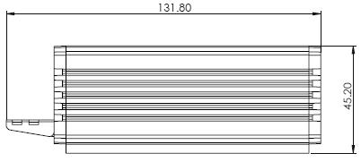
45 13. Dimensions Unit: mm 45

46 46
47 14. Specifications Image Pickup Element Effective Picture Elements Resolution Signal System S/N Ratio Min. Illumination Electric Shutter Video 1/2.8 type progressive scan CMOS sensor Approx Mega pixels HD / FHD / SD (CVBS only) HDMI & SDI: 1080p 59.94/50/29.97/ i 59.94/50 720p 59.94/50 CVBS: 480i, 576i 50 db Color : 0.4 lx (F1.6, 1/30 sec, 50IRE, Gain: High) B/W : 0.03 lx (F1.6, 1/30 sec, 50IRE, Gain: High) 1/25 (1/30), 1/50 (1/60), 1/120 (1/100), 1/250, 1/500, 1/1000 sec Gamma Control Off / Normal / Standard Mode 1-4 Iris Control Auto / Manual Digital Noise Reductions 0-5 On-Screen Display (OSD) English White Balance AWB / MWB / One push WB / Outdoor / Indoor / Fluorescent AGC / Gain Control Auto / Manual (0 to 39 step) Max. Gain Limit (9 to 39 step) Zoom Ratio 30x Optical Zoom Mirror Camera Title (OSD) Color Bar Focus Mode Day & Night (IR) OFF / Horizontal / Vertical / H+V ON / OFF On / Off (Full Bar) Auto / Manual Auto / Color / BW Pan / Tilt / Zoom Pan/Tilt Range Pan: 270, Tilt: +90 to -20 Pan/Tilt Speed Manual: 1~150 /Sec Swing: 1~150 /Sec Initialization Time 30 sec 47
48 Coordinate Report Lens Type Focal Length Angle of View (Horizontal) Filter RoHS Video Output Video Format Output P, T, Z (While Panning, Tilting and Zooming ) by frame Lens 30x Optical Zoom F=4.3 mm (WIDE) to 129 mm (TELE) F1.6 to F4.7 Approx degrees (WIDE END) / 2.3 degrees (TELE END) M52.0x0.75 Thread with UV Protection Compliant Video Output HDMI (V1.3) x 1 HD-SD-SDI x 1 CVBS x 1 HDBaseT x 1 to PTC-150T/TW Receiver Box 1 Vp-p / 75 Ohms Control Protocol VISCA / HDbaseT Remote Control RS-422 & HDBaseT by RJ-45 interface F/W Update USB 2.0 IR Control One IR controller Receiver Box Protocol DVIP / HDBaseT Video Out HDMI (V1.3) x 1 Power DC 48V (Please connect DC 48V to Receiver Box) Control DVIP by RJ-45 interface HDBaseT Distance Up to 100M by Cat.6 cable (RJ-45 interface) Others Moving Noise while Tilt <=25dB Moving Noise while Pan <=25dB Operating Temperature 0 C ~ 50 C Storage Temperature - 10 C ~ 60 C Operating Humidity: 10 % to 80 % (no condensation) Certifications CE / FCC Class A 48
49 Cable Selection Video Resolutions (HDBaseT Connection) Cable Range Video Resolution CAT5e/6 100 meters 70 meters Up to 1080p, 60Hz, 36 bpp. Data rates lower than 5.3 Gbps or below 255 MHz TMDS clock. Ultra HD video formats: HDMI Deep color: 1080p, 60, 48 bpp. CAT6a/CAT7 100 meters(*) 4K x 2K Data rates higher than 5.3 Gbps or above 255 MHz TMDS clock. * Recommended Cables for Ultra-HD video at 100 Meter range Type P/N Manufacturer Web CAT7 FR-LSZH Teldor S/FTP CAT6A HFFR Teldor H-STP CAT Earthline 49


50 Sep Ver: E5
HD/SD-SDI HDBaseT PTZ CAMERA PTC-150T/ PTC-150TW. Instruction Manual.
 HD/SD-SDI HDBaseT PTZ CAMERA PTC-150T/ PTC-150TW Instruction Manual www.datavideo.com Table of Contents TABLE OF CONTENTS... 2 FCC COMPLIANCE STATEMENT... 4 WARNINGS AND PRECAUTIONS... 4 WARRANTY... 5
BC-200 Instruction Manual
 4K BLOCK CAMERA BC-200 Instruction Manual Table of Contents FCC COMPLIANCE STATEMENT... 4 WARNINGS AND PRECAUTIONS... 4 WARRANTY... 5 STANDARD WARRANTY... 5 THREE YEAR WARRANTY... 6 DISPOSAL... 7 1. INTRODUCTION...
BC-80 BLOCK CAMERA. Instruction Manual
 BC-80 BLOCK CAMERA Instruction Manual Table of Contents FCC COMPLIANCE STATEMENT... 4 WARNINGS AND PRECAUTIONS... 4 WARRANTY... 5 STANDARD WARRANTY... 5 THREE YEAR WARRANTY... 6 DISPOSAL... 7 1. INTRODUCTION...
AUDIO DELAY BOX WITH MICROPHONE INPUT AD-100M. Instruction manual.
 AUDIO DELAY BOX WITH MICROPHONE INPUT AD-100M Instruction manual www.datavideo.com Table of Contents FCC COMPLIANCE... 3 WARNINGS AND PRECAUTIONS... 3 WARRANTY... 4 STANDARD WARRANTY... 4 THREE YEAR WARRANTY...
b. Time Setting c. Volume Setting d. Backlight Setting e. Sleep Setting f. Pin Setting g. Joystick Calibration...
 0 Warnings and Precautions... 2 Warranty... 3 Disposal... 3 1. Product Overview... 4 2. Features... 4 3. Functions... 4 4. System Diagram... 7 5. Setting Menu... 9 6. Menu operation... 10 a. Camera Setting...
HD/SD-SDI HDBaseT PTZ CAMERA PTC-150T/ PTC-150TW. Instruction Manual.
 HD/SD-SDI HDBaseT PTZ CAMERA PTC-150T/ PTC-150TW Instruction Manual www.datavideo.com Table of Contents FCC COMPLIANCE STATEMENT... 4 WARNINGS AND PRECAUTIONS... 4 WARRANTY... 5 STANDARD WARRANTY... 5
PTC-150/ PTC-150W Instruction Manual
 HD/SD-SDI PTZ CAMERA PTC-150/ PTC-150W Instruction Manual Table of Contents FCC COMPLIANCE STATEMENT... 4 WARNINGS AND PRECAUTIONS... 4 WARRANTY... 6 STANDARD WARRANTY... 6 THREE YEAR WARRANTY... 6 DISPOSAL...
WARNINGS AND PRECAUTIONS... 3 PACKING LIST... 5 FRONT PANEL... 5 REAR PANEL... 6 MENU SETTINGS... 7 EXAMPLE SETUP SPECIFICATIONS...
 AUDIO DELAY sax AD-1 aam Quick Start Guide WARNINGS AND PRECAUTIONS... 3 PACKING LIST... 5 FRONT PANEL... 5 REAR PANEL... 6 MENU SETTINGS... 7 EXAMPLE SETUP... 11 SPECIFICATIONS... 11 SERVICE & SUPPORT...
4K PTZ CAMERA PTC-200 Instruction Manual
 4K PTZ CAMERA PTC-200 Instruction Manual Table of Contents FCC Compliance Statement 4 Warnings and Precautions 4 Warranty 5 Standard Warranty 5 Three Year Warranty 6 Disposal 6 1. Product Overview 7 2.
BC-200T Instruction Manual
 4K HDBaseT BLOCK CAMERA BC-200T Instruction Manual Table of Contents FCC COMPLIANCE STATEMENT... 4 WARNINGS AND PRECAUTIONS... 4 WARRANTY... 6 STANDARD WARRANTY... 6 THREE YEAR WARRANTY... 6 DISPOSAL...
Warnings and Precautions
 Warnings and Precautions 1. Read all of these warnings and save them for later reference. 2. Follow all warnings and instructions marked on this unit. 3. Unplug this unit from the wall outlet before cleaning.
Network Camera. Quick Guide DC-B1203X. Powered by
 Network Camera Quick Guide DC-B1203X Powered by Safety Precautions English WARNING RISK OF ELECTRIC SHOCK DO NOT OPEN WARNING: TO REDUCE THE RISK OF ELECTRIC SHOCK, DO NOT REMOVE COVER (OR BACK). NO USER-SERVICEABLE
QIT600F1 USER'S GUIDE
 QIT600F1 USER'S GUIDE 1 IMPORTANT SAFEGUARDS Warnings: 1. Read all of these instructions. Save these instructions for later use, please. 2. Unplug this monitor from the wall outlet before cleaning. Do
Table of Contents. Standard Warranty 5. Two Year Warranty Remote Control Functions On-Screen Menu Step 1 DIP Switch Setting 21
 1 Table of Contents Warnings and Precautions 4 Warranty 5 Standard Warranty 5 Two Year Warranty 5 Disposal 5 1. Product Overview 6 2. Features 6 3. Location and Function of Parts 7 4. System Diagram 8
Avonic AV-CON300. PTZ Camera Controller
 Avonic AV-CON300 PTZ Camera Controller User Manual Version 1.0 Update notes: Join Avonic linkedin.com/company/avonic twitter.com/avonic1 facebook.com/avonic www.avonic.eu 1 Contents Inhoud Contents...
Contents. Warnings and Precautions...3. Warranty...4. Disposal...4. Packing List...5. Introduction...5. Features...6. Example MCU-100 Set Up...
 Contents Warnings and Precautions...3 Warranty...4 Disposal...4 Packing List...5 Introduction...5 Features...6 Example MCU-100 Set Up...7 Connections and Controls...8 MCU-100 Keyboard Guide...10 How to
HD SDI 1080P ICR OSD 42 IR Vandal Dome Camera
 HDVDX42-4AVF HD SDI 1080P ICR OSD 42 IR Vandal Dome Camera Optional Bracket MB-4VD USER MANUAL FEATURES SDI 1080P - 1920 x 1080, 30fps, 2.0 Megapixel 1/2.8 2.0 Megapixel Progressive Scan CMOS 3.3mm~12mm
Thank you for purchasing our product. If there are any questions, or requests, please do not hesitate to contact the dealer.
 User Manual Thank you for purchasing our product. If there are any questions, or requests, please do not hesitate to contact the dealer. This manual may contain several technical incorrect places or printing
ST-HDC2FD QUICK START GUIDE. Or contact technical
 ST-HDC2FD QUICK START GUIDE www.nacebrands.com www.securitytronix.com User Manual Thank you for purchasing our product. If there are any questions, or requests, please do not hesitate to contact the dealer
HD SDI 1080p WDR DNR 24 IR OSD Bullet Camera
 HD21B24-940 HD SDI 1080p WDR DNR 24 IR OSD Bullet Camera USER MANUAL FEATURES SDI 1080p - 1920 x 1080 1/2.9" Sony Exmor 4.0mm Fixed Lens 0.5 Lux 24 IR LED IR distance up to 50ft / 24m 700mA max 12V DC
VZ-TVI-B3040MZVF 3MP Motorized VF EXIR Bullet Camera
 VZ-TVI-B3040MZVF 3MP Motorized VF EXIR Bullet Camera User Manual User Manual Thank you for purchasing our product. If there are any questions, or requests, please do not hesitate to contact the dealer.
CONTENTS PRODUCT FEATURES... EG-2 SAFETY PRECAUTIONS... EG-2 PARTS DESCRIPTION... EG-3 INSTALLATION AND ADJUSTMENT... EG-4 SPECIFICATIONS...
 Thank you for your purchase of this product. Before operating the product, please read this instruction manual carefully to ensure proper use of the product. Please store this instruction manual in a safe
EVO-TM2A EVO-TM2B Touch Screen Monitor
 User Manual Revision v1.3 Dec. 2010 EVO-TM2A EVO-TM2B Touch Screen Monitor Copyright 2010 August All Rights Reserved Manual Version 1.3 Part Number: The information contained in this document is subject
CM-Z2212GY. Outdoor IR Speed Dome PTZ Camera
 Outdoor IR Speed Dome PTZ Camera User s Guide CM-Z2212GY 1201-1205, Sangda Mansion, High Technology Park, SAFETY PRECAUTIONS WARNING 1. Be sure to use only the standard adapter that is specified in the
Prestigio P371 Users manual
 Prestigio P371 Users manual 1. IMPORTANT INFORMATION WARNING: TO PREVENT FIRE OR SHOCK HAZARD, DO NOT EXPOSE THIS MONITOR TO LIQUIDS OR MOISTURE. HIGH VOLTAGE EXISTS ON THIS MONITOR. DO NOT REMOVE THE
Supplied Accessories.
 Precautions. Safety Tips. Please read this manual carefully before using the camera. Avoid damage from stress, violent vibration or liquid intrusion during transportation, storage or installation. Take
HuddleCamHD 10X-USB2
 HuddleCamHD 10X-USB2 USB 2.0 PTZ CAMERA INSTALLATION & OPERATION MANUAL Please check HUDDLECAMHD.com for the most up to date version of this document Precautions. Safety Tips. Please read this manual carefully
CM55-VCU USB 3.0 HD PTZ Camera User Manual v2.1
 CM55-VCU USB 3.0 HD PTZ Camera User Manual v2.1 www.avonic.eu 1 Safety Notes Before installing the device, please read this manual carefully and follow instructions indicated to ensure proper operation.
TURBO HD D7T Series Dome Camera
 TURBO HD D7T Series Dome Camera User Manual UD02018B User Manual Thank you for purchasing our product. If there are any questions, or requests, do not hesitate to contact the dealer. This manual applies
User Manual TL-TP70-HDC 70m HDBaseT Extender Set for HDMI, RS232 & IR All Rights Reserved Version: TL-TP70-HDC _160926
 User Manual TL-TP70-HDC 70m HDBaseT Extender Set for HDMI, RS232 & IR All Rights Reserved Version: TL-TP70-HDC _160926 Preface Read this user manual carefully before using this product. Pictures shown
DC-D4213RX DC-D4213WRX
 Network Camera Quick Guide DC-D4213RX DC-D4213WRX Powered by Safety Precautions WARNING RISK OF ELECTRIC SHOCK DO NOT OPEN WARNING: TO REDUCE THE RISK OF ELECTRIC SHOCK, DO NOT REMOVE COVER (OR BACK).
CONTENTS PRODUCT FEATURES... EG-2 SAFETY PRECAUTIONS... EG-2 PARTS DESCRIPTION... EG-3 INSTALLATION AND ADJUSTMENT... EG-4 SPECIFICATIONS...
 Thank you for your purchase of this product. Before operating the product, please read this instruction manual carefully to ensure proper use of the product. Please store this instruction manual in a safe
VC-B10U HD Camera (USB 3.0 Camera) Installation Manual - English
 Installation Manual - English") VC-B10U HD Camera (USB 3.0 Camera) Installation Manual - English [Important] To download the latest version of Quick Start Guide, multilingual user manual, software, or driver, etc., please visit Lumens
VC-B10U HD Camera (USB 3.0 Camera) Installation Manual - English [Important] To download the latest version of Quick Start Guide, multilingual user manual, software, or driver, etc., please visit Lumens
The Symphony Keyboard is available with either a 2D or 3D joystick. The 3D Joystick controls zoom in and out, as well as direction.
 1 SYMPHY KEYBOARD 2 Overview The Symphony Keyboard is available with either a 2D or 3D joystick. The 3D Joystick controls zoom in and out, as well as direction. The unit provides all the functions required
Supplied Accessories.
 Precautions. Safety Tips. Please read this manual carefully before using the camera. Avoid damage from stress, violent vibration or liquid intrusion during transportation, storage or installation. Take
1. Introduction Features Checking List Installation Install the Pedestal Connect Your Monitor to Computer...
 E27M5G 27 " W User Manual M Series L E D B A C K L I G H T M o n i to r Content F.C.C STATEMENT IMPORTANT SAFEGUARDS 1. Introduction 6 1.1 Features...6 1.2 Checking List...6 2. Installation 7 2.1 Install
SERVICE MANUAL 1/3 SONY DSP COLOR CCD CAMERA 600TVL O.S.D. WDR SERIES
 SERVICE MANUAL 1/3 SONY DSP COLOR CCD CAMERA 600TVL O.S.D. WDR SERIES The serial number of this product may be found on the bottom of the unit. You should note the serial number of this unit in the space
DANNOVO HD USB 3.0 PTZ Video Conference Camera User Manual
 DANNOVO HD USB 3.0 PTZ Video Conference Camera User Manual V 2.3(ENGLISH VERSION) Please read this Manual before set up Camera, and stick to its requirements strictly for Safety reason. Suggest you save
Digital Photo Picture Frame With Built-in Weather Station. User s Manual
 Digital Photo Picture Frame With Built-in Weather Station User s Manual 20070731 Important Safety Instructions CAUTION: These servicing instructions are for use by qualifi ed service personnel only. To
DC-D2212R / DC-D2212WR
 Network Camera Quick Guide / DC-D2212WR Powered by Safety Precautions WARNING RISK OF ELECTRIC SHOCK DO NOT OPEN WARNING: TO REDUCE THE RISK OF ELECTRIC SHOCK, DO NOT REMOVE COVER (OR BACK). NO USER-SERVICEABLE
Network Camera. Quick Guide DC-D1223WX. Powered by
 Network Camera Quick Guide DC-D1223WX Powered by Safety Precautions WARNING RISK OF ELECTRIC SHOCK DO NOT OPEN WARNING: TO REDUCE THE RISK OF ELECTRIC SHOCK, DO NOT REMOVE COVER (OR BACK). NO USER-SERVICEABLE
User Manual. Stoltzen SHSP14 HDMI Splitter 1x4. 4K HDMI Splitter 1x4. All Rights Reserved. Version: SHSP14_2016V2
 User Manual 4K HDMI Splitter 1x4 All Rights Reserved Version: SHSP14_2016V2 SAFETY PRECAUTIONS To insure the best from the product, please read all instructions carefully before using the device. Save
Monochrome Camera. Features. User manual
 Monochrome Camera LTC0330/11 LTC0330/21 LTC0350/11 LTC0350/21 LTC0330/51 LTC0330/61 LTC0350/51 LTC0350/61 Features To obtain the best results from your new camera, read these instructions carefully before
Professional Pan Tilt Zoom Camera ST-HD-PTZ-2MP INSTALLATION MANUAL
 Professional Pan Tilt Zoom Camera ST-HD-PTZ-2MP INSTALLATION MANUAL www.nacebrands.com www.securitytronix.com Description: The ST-HD-PTZ-2MP is a professional-grade intelligent dome color camera with Pan/Tilt/Zoom
CV620-BK2/WH2 Full-HD PTZ Camera
 CV620-BK2/WH2 Full-HD PTZ Camera Installation Guide Ver 1.1-100517a Table of Contents Safety Instructions... 4 Package Contents... 6 Product Overview... 7 3.1 Overview... 7 3.2 Description of LED indicator...
TURBO HD TVI Bullet & Turret Camera
 TURBO HD TVI Bullet & Turret Camera User Manual UD03589B User Manual Thank you for purchasing our product. If there are any questions, or requests, do not hesitate to contact the dealer. This manual applies
HuddleCamHD 3x USB 2.0 PTZ CAMERA INSTALLATION & OPERATION MANUAL
 HuddleCamHD 3x USB 2.0 PTZ CAMERA INSTALLATION & OPERATION MANUAL Precautions. Safety Tips. Please read this manual carefully before using the camera. Avoid damage from stress, violent vibration or liquid
Motion LED Floodlight Covert Color Camera
 ESFL-X650 Operational Manual Motion LED Floodlight Covert Color Camera Camera FEATURES 1/3 Sony ExView HAD CCD II 650 TV Lines (Color) / 700TV Lines (B&W) 3.6mm Board Lens 0.01 Lux @ F2.0; 0 Lux @ IR on
Contents. 1 Notes Product Introduction Product Structure
 Contents 1 Notes...- 1-2 Product Introduction...- 2-2.1 Production Instruction... - 2-2.2 Product Feature... - 2-3 Product Structure...- 3-4 Technical Parameters...- 6-5 OSD Menu tree...- 7-6 Product Installation...-
PTZ CAMERA CONTROL UNIT. RMC-180 Instruction manual.
 PTZ CAMERA CONTROL UNIT RMC-180 Instruction manual www.datavideo.com Table of Contents FCC COMPLIANCE STATEMENT... 3 WARNINGS AND PRECAUTIONS... 3 WARRANTY... 4 STANDARD WARRANTY... 4 THREE YEAR WARRANTY...
DC-V3213XJ-4.3mm DC-V3213XJ-2.5mm
 Network Camera Quick Guide DC-V3213XJ-4.3mm DC-V3213XJ-2.5mm Powered by Safety Precautions WARNING RISK OF ELECTRIC SHOCK DO NOT OPEN WARNING: TO REDUCE THE RISK OF ELECTRIC SHOCK, DO NOT REMOVE COVER
Nearus USB2.0 Camera Manual NU-350-USB2PTZ-B
 Nearus USB2.0 Camera Manual NU-350-USB2PTZ-B Safety Tips Please read this manual carefully before installing the camera. Keep the camera away from violent vibration, physical stress, moisture, extreme
Network Camera. Quick Guide DC-T3243HRX. Powered by
 Network Camera Quick Guide DC-T3243HRX Powered by Safety Precautions WARNING RISK OF ELECTRIC SHOCK DO NOT OPEN WARNING: TO REDUCE THE RISK OF ELECTRIC SHOCK, DO NOT REMOVE COVER (OR BACK). NO USER-SERVICEABLE
Camera Installation Manual Ver 1.0. Pan, Tilt and Zoom Dome Camera / PTZ
 Camera Installation Manual Ver 1.0 1 Introduction Features 3 Components 4 System Configuration 5 2 Installation Wall Mount 6 Ceiling Mount 7 Final Assembly 8 3 Camera Addressing Camera Address Setting
USERS GUIDE MCX-STH. 3G SDI to HDMI Converter. Manual Number:
 USERS GUIDE MCX-STH 3G SDI to HDMI Converter i Manual Number: 151226 SAFETY INSTRUCTIONS Please review the following safety precautions. If this is the first time using this model, then read this manual
SECTION 1 GENERAL DESCRIPTION
 1-1 IMPORTANT SAFEGUARDS 1. Read Instructions All the safety and operating instructions should be read before the product is operated. 2. Retain Instructions The safety instructions and instruction manual
HD SDI 1080P ICR 360 Fisheye Indoor Camera
 HD5FE-8012 HD SDI 1080P ICR 360 Fisheye Indoor Camera USER MANUAL FEATURES SDI 1080P - 1920 x 1080 SDI / HDMI / 4 Channel CVBS Output 1/3.2 Color CMOS QSXGA 5 Megapixel 1.19mm Megapixel Lens Built-in Microphone
HDBaseT EXTENDER B-520-TX-230-IR B-520-TX-330-IR INSTALLATION MANUAL
 HDBaseT EXTENDER B-50-TX-30-IR B-50-TX-330-IR INSTALLATI MANUAL IMPORTANT SAFETY INSTRUCTIS To reduce the risk of fire or electric shock, read and follow all instructions and warnings in this manual. Keep
ST-PTZ High-Speed Intelligent Dome PTZ Color Camera
 INSTALLATION MANUAL ST-PTZ550-27 High-Speed Intelligent Dome PTZ Color Camera Copyright North American Cable Equipment, Inc. 1 PACKAGE CONTENTS This package contains: One ST-PTZ550-27 high-speed intelligent
HuddleCamHD 30x USB 3.0 PTZ CAMERA INSTALLATION & OPERATION MANUAL
 HuddleCamHD 30x USB 3.0 PTZ CAMERA INSTALLATION & OPERATION MANUAL Please check HUDDLECAMHD.com for the most up to date version of this document Precautions. Safety Tips. Please read this manual carefully
USER MANUAL. 1080P Eco - 4 in 1 Series
 USER MANUAL 1080P Eco - 4 in 1 Series Contents 1) CAUTIONS 2 ) Product Introduction 2.1 Camera Introduction 2.2 Product Features 3) Menu Instruction 4) Product Installation 4.1 General Notes 4.2 Installation
VITEK VTD-THD2RFE VTC-THT2RFE VTC-THB2RFE. 2.1 Megapixel Indoor/Outdoor HD-TVI/ AHD/CVI/CVBS IR Cameras
 VITEK FEATURES 1/2.9 2.1 Megapixel Progressive Scan CMOS Sensor HD-TVI, AHD, CVI, and CVBS Video Output 3.6mm & 2.8mm Fixed Lens Options Up to 70 IR Range Digital Wide Dynamic Range (D-WDR) True Mechanical
HD Analog Camera User's Manual
 HD Analog Camera User's Manual Model No. CV-CFN103L CV-CFN103LN Version 1.0.0 Table of Contents 1 General Introduction... 1 1.1 Overview... 1 1.2 Features... 1 1.3 Functions... 1 1.4 Specifications...
HuddleCamHD 3XA with Audio USB 2.0 PTZ Camera w/ built-in Mic Array Installation and Operation Manual
 HuddleCamHD 3XA with Audio USB 2.0 PTZ Camera w/ built-in Mic Array Installation and Operation Manual Precautions Safety Tips Please be aware any deviation from these tips may void your warranty Please
PTZ Optics Affordable HDMI, HD-SDI, IP and USB video conferencing cameras
 PTZ Optics Affordable HDMI, HD-SDI, IP and USB video conferencing cameras as PTZ Optics Affordable HDMI, HD-SDI, IP and USB video conferencing cameras as P T Z OPTICS 12X USB PTZ OPTICS Video Conferencing
Version 1.0 March 2014 OLC 10.1
 User Manual Version 1.0 March 2014 OLC 10.1 Copyright 2014 All Rights Reserved Manual Version 1.0 The information contained in this document is subject to change without notice. We make no warranty of
INSTRUCTION MANUAL DISTRIBUTION UNIT. Please read this manual thoroughly before use, and keep it handy for future reference.
 INSTRUCTION MANUAL DISTRIBUTION UNIT Please read this manual thoroughly before use, and keep it handy for future reference. ISSUE 1 May 2006 LIMITATION OF LIABILITY THE INFORMATION IN THIS PUBLICATION
TruVision IP Thermal Camera Installation Guide
 TruVision IP Thermal Camera Installation Guide P/N 1073335-EN REV B ISS 19OCT17 Copyright Trademarks and patents Manufacturer Certification 2017 United Technologies Corporation, Interlogix is part of UTC
User Manual SP2-4K. 4K HDMI Splitter 1x2. All Rights Reserved. Version: SP2-4K_2016V1.0
 User Manual SP2-4K 4K HDMI Splitter 1x2 All Rights Reserved Version: SP2-4K_2016V1.0 SAFETY PRECAUTIONS To insure the best from the product, please read all instructions carefully before using the device.
SERVICE MANUAL 1/3 SONY DSP COLOR CCD CAMERA OVER 650TVL SERIES
 SERVICE MANUAL 1/3 SONY DSP COLOR CCD CAMERA OVER 650TVL SERIES The serial number of this product may be found on the bottom of the unit. You should note the serial number of this unit in the space provided
VC-A51S HD Camera (PTZ Video Camera) Installation Guide - English
 Installation Guide - English") VC-A51S HD Camera (PTZ Video Camera) Installation Guide - English [Important] To download the latest version of Quick Start Guide, multilingual user manual, software, or driver, etc., please visit Lumens
VC-A51S HD Camera (PTZ Video Camera) Installation Guide - English [Important] To download the latest version of Quick Start Guide, multilingual user manual, software, or driver, etc., please visit Lumens
Camera A14 and A34 Dome Camera
 Camera A14 and A34 Dome Camera Quick Start Guide Thank you for purchasing our product. If there are any questions, or requests, please do not hesitate to contact the dealer. About This Manual: This manual
HD Analog Camera User s Manual
 HD Analog Camera User s Manual Model No. CV-CPW103L CV-CPW103LN Version 1.0.0 Table of Contents 1 General Introduction... 1 1.1 Overview... 1 1.2 Features... 1 1.3 Functions... 1 1.4 Specifications...
HD CCTV Digital Video Camera
 HD CCTV Digital Video Camera OPERATION MANUAL M133-HDX210-001 Thank you for choosing our high quality camera. Before attempting to connect or operate, please read and follow these instructions. CAUTION
VITEK VTD-IR2811DN FEATURES: 1/3 Color CCD with 560 TV of Lines Resolution (600 TV Lines in B/W mode)
") VTD-IR2811DN 560 TV Line Indoor Day/Night IR Dome Camera VITEK FEATURES: 1/3 Color CCD with 560 TV of Lines Resolution (600 TV Lines in B/W mode) 20 Infrared LEDs enable Viewing in Total Darkness up to
VTD-IR2811DN 560 TV Line Indoor Day/Night IR Dome Camera VITEK FEATURES: 1/3 Color CCD with 560 TV of Lines Resolution (600 TV Lines in B/W mode) 20 Infrared LEDs enable Viewing in Total Darkness up to
Avonic CM-CON100. PTZ Camera Keyboard Controller
 Avonic CM-CON100 PTZ Camera Keyboard Controller User Manual Version 2.0 Update notes: Join Avonic linkedin.com/company/avonic twitter.com/avonic1 facebook.com/avonic www.avonic.eu 1 Contents Inhoud Contents...
Architecture and Engineering Specifications SANYO VCC-HD Megapixel Full-HD Day/Night 10x AF High Speed Dome Camera
 Architecture and Engineering Specifications SANYO VCC-HD5600 2 Megapixel Full-HD Day/Night 10x AF High Speed Dome Camera A. General Characteristics: 1. Full Pan-Tilt-Zoom Functionality with continuous
HDMI/HDBT 1x4 Splitter. Installation & Operation Manual. MuxLab Inc A / SE A
 500424 MuxLab Inc. 2016 94-000808-A / SE-000808-A SAFETY PRECAUTIONS To insure the best from the product, please read all instructions carefully before using the device. Save this manual for further reference.
Owner s Instruction Manual
 Owner s Instruction Manual Advanced Healthcare Telephone Model 5150 Contents IMPORTANT SAFETY INSTRUCTIONS...3 BOX CONTENTS...4 FEATURES...4 ON/OFF SWITCH...4 DIAL BUTTONS...4 RECEIVER VOLUME CONTROL...4
DC120 Visual Presenter. User Manual
 DC120 Visual Presenter User Manual [Important] Please visit Lumens http://www.lumens.com.tw/goto.htm to download the latest software, drivers, and documentation English - 0 Table of contents Copyright
Quick Start Guide. Thank you for purchasing our products. Please read the cut-sheet carefully before operating. Safety Precaution
 Quick Start Guide Item Number: IV-BV7660IR-AHDM Thank you for purchasing our products. Please read the cut-sheet carefully before operating. Safety Precaution Warning * To prevent fire or shock hazard,
PTZ Conference Room USB Camera
 PTZ Conference Room USB Camera P/N 35520 User's Manual SAFETY WARNINGS AND GUIDELINES Please read this entire manual before using this device, paying extra attention to these safety warnings and guidelines.
EVO-TP Hardware System
 User Manual Revision v1.3 February 2010 EVO-TP Hardware System Copyright 2009 February All Rights Reserved Manual Version 1.1 Part Number: The information contained in this document is subject to change
Hidden Camera. 1080P Pro 4 in 1 Series
 Hidden Camera 1080P Pro 4 in 1 Series Contents 1) CAUTIONS 2 ) Product Introduction 2.1 Camera Introduction 2.2 Product Features 3) Menu Setup 4) Product Installation 4.1 General Notes 4.2 Installation
TURBO HD H5T Series Bullet Camera
 TURBO HD H5T Series Bullet Camera User Manual UD05381B User Manual Thank you for purchasing our product. If there are any questions, or requests, do not hesitate to contact the dealer. This manual applies
DC-D3233RX-N / DC-D3233X-N
 Network Camera Quick Guide DC-D3233RX-N / DC-D3233X-N Powered by Safety Precautions Important Safeguards WARNING RISK OF ELECTRIC SHOCK DO NOT OPEN WARNING: TO REDUCE THE RISK OF ELECTRIC SHOCK, DO NOT
MultiPlex 15 Touch Screen. User s Manual
 MultiPlex 5 Touch Screen User s Manual Preface Precautions. READ INSTRUCTIONS: All the safety and operating instructions should be read before the LCD monitor is operated.. RETAIN INSTRUCTIONS: The safety
Network Camera. Quick Guide DC-D3C33HRX. Powered by
 Network Camera Quick Guide DC-D3C33HRX Powered by Safety Precautions Important Safeguards WARNING RISK OF ELECTRIC SHOCK DO NOT OPEN WARNING: TO REDUCE THE RISK OF ELECTRIC SHOCK, DO NOT REMOVE COVER (OR
User Manual TL-TP70-HDIR. 70m Extender with ARC and IR. All Rights Reserved. Version: TL-TP70-HDIR_160708
 User Manual TL-TP70-HDIR 70m Extender with ARC and IR All Rights Reserved Version: TL-TP70-HDIR_160708 TL-TP70-HDIR User Manual Preface Read this user manual carefully before using this product. Pictures
KEZ-c1TR28V12XIR HD-TVI 720p Low Light Varifocal IP66 EXIR Turret Cameras with OSD, CVBS Test Output and UTC Control
 KEZ-c1TR28V12XIR HD-TVI 720p Low Light Varifocal IP66 EXIR Turret Cameras with OSD, CVBS Test Output and UTC Control Quick Operation Guide Thank you for selecting this KT&C Omni EZHD Series product. For
Table of Contents. Federal Communications Commission (FCC) Statement...2
 Statement...2") Contents Table of Contents Federal Communications Commission (FCC) Statement...2 Important Safety Instructions...3 Chapter 1 Introduction Features...6 Package Contents...7 Front View and Controls...8 Installing
Contents Table of Contents Federal Communications Commission (FCC) Statement...2 Important Safety Instructions...3 Chapter 1 Introduction Features...6 Package Contents...7 Front View and Controls...8 Installing
USERS GUIDE ASP-18H-4K. HDMI 4K2K 1x8 Splitter with EDID Management. Manual Number:
 USERS GUIDE ASP-18H-4K HDMI 4K2K 1x8 Splitter with EDID Management i Manual Number: 141110 SAFETY INSTRUCTIONS Please review the following safety precautions. If this is the first time using this model,
GV-SD2322-IR (22x) Outdoor Low Lux IR IP Speed Dome
 Outdoor Low Lux IR IP Speed Dome") - 1 - GV-SD2322-IR (22x) Outdoor Low Lux IR IP Speed Dome 1/2.8" progressive scan low lux CMOS sensor Min. illumination at 0.01 lux (B/W) and 0.03 lux (color) Triple streams from H.264 and MJEPG Up to
- 1 - GV-SD2322-IR (22x) Outdoor Low Lux IR IP Speed Dome 1/2.8" progressive scan low lux CMOS sensor Min. illumination at 0.01 lux (B/W) and 0.03 lux (color) Triple streams from H.264 and MJEPG Up to
Network Camera. Quick Guide DC-S1283WRX. Powered by
 Network Camera Quick Guide DC-S1283WRX Powered by Safety Precautions Important Safeguards WARNING RISK OF ELECTRIC SHOCK DO NOT OPEN WARNING: TO REDUCE THE RISK OF ELECTRIC SHOCK, DO NOT REMOVE COVER (OR
TURBO HD 4K Series Bullet Camera
 TURBO HD 4K Series Bullet Camera User Manual User Manual Thank you for purchasing our product. If there are any questions, or requests, do not hesitate to contact the dealer. This manual applies to the
DC210 Visual Presenter. User Manual
 DC210 Visual Presenter User Manual [Important] To download the latest version of Quick Start Guide, multilingual user manual, software, or driver, etc., please visit Lumens http://www.lumens.com.tw/goto.htm
Network Dome Camera Quick Start Guide
 Thank you for purchasing our product. If there are any questions, or requests, please do not hesitate to contact us. About This Document This manual may contain several technical incorrect places or printing
PL1500M LCD Monitor USER'S GUIDE.
 PL1500M LCD Monitor USER'S GUIDE www.planar.com Content Operation Instructions...1 Safety Precautions...2 First Setup...3 Front View of the Product...4 Rear View of the Product...5 Quick Installation...6
FUTURE CALL. Future Call Model FC-1204 Totally Hands Free Voice Activated Dialing and Answering Telephone OWNER S MANUAL AND OPERATING INSTRUCTIONS
 FUTURE CALL Future Call Model FC-1204 Totally Hands Free Voice Activated Dialing and Answering Telephone OWNER S MANUAL AND OPERATING INSTRUCTIONS Welcome to your new Totally Hands Free Voice Activated
User Manual TL-FO-HD. 4K Optical Fiber Extender. All Rights Reserved. Version: TL-FO-HD_160628
 User Manual TL-FO-HD 4K Optical Fiber Extender All Rights Reserved Version: TL-FO-HD_160628 Preface Read this user manual carefully before using this product. Pictures shown in this manual is for reference