GV-IPCam H.264. User's Manual
|
|
|
- Lester Welch
- 5 years ago
- Views:
Transcription

1 GV-IPCam H.264 User's Manual Before attempting to connect or operate this product, please read these instructions carefully and save this manual for future use.
2 2010 GeoVision, Inc. All rights reserved. Under the copyright laws, this manual may not be copied, in whole or in part, without the written consent of GeoVision. Every effort has been made to ensure that the information in this manual is accurate. GeoVision, Inc. makes no expressed or implied warranty of any kind and assumes no responsibility for errors or omissions. No liability is assumed for incidental or consequential damages arising from the use of the information or products contained herein. Features and specifications are subject to change without notice. GeoVision, Inc. 9F, No. 246, Sec. 1, Neihu Rd., Neihu District, Taipei, Taiwan Tel: Fax: Trademarks used in this manual: GeoVision, the GeoVision logo and GV series products are trademarks of GeoVision, Inc. Windows and Windows XP are registered trademarks of Microsoft Corporation. October 2010
3 Preface Welcome to the GV-IPCAM H.264 User s Manual. The GV-IPCAM H.264 has a series of models designed to meet different needs. This Manual is designed for the following models and firmware versions: Model Model Number Firmware Version GV-BX110D Fixed Lens V1.07 Varifocal Lens Box Camera GV-BX120D Varifocal Lens V1.0 GV-BX220D Varifocal Lens V1.0 GV-BX320D Varifocal Lens V1.0 Mini Fixed Dome GV-MFD110 V1.07 Bullet Camera GV-BL110D V1.07 NTSC PTZ Camera GV-PTZ010D PAL V1.07 PT Camera GV-PT110D V1.07 I
4 Contents Naming and Definition... 1 Note for Recording... 1 Note for Firmware Upgrade... 2 Chapter 1 Introduction System Requirement... 4 Chapter 2 Box Camera Packing List Features Options Overview GV-BX110D GV-BX120D / 220D / 320D Focus Adjustment Optional Installation C-Mount Lenses Infrared Illuminators I/O Terminal Block Pin Assignment...14 Chapter 3 Mini Fixed Dome Packing List Features Options Overview Focus Adjustment II
5 Chapter 4 Bullet Camera Packing List Features Options Installation Connecting to the Data Cable Adjusting Bullet Camera s Angles Adjusting Lens and Inserting a Micro SD Card Installing the Sun-Shield Cover...34 Chapter 5 PTZ Camera Packing List Features Options Installation Overview Focus Adjustment I/O Terminal Block Pin Assignment PTZ Control The PTZ Control Panel Automatic Focus PTZ Camera Settings Image Settings Preset Settings Sequence Settings Auto Pan Settings System Configuration...64 III
6 Chapter 6 PT Camera Packing List Features Options Installation Overview Focus Adjustment I/O Terminal Block Pin Assignment PT Control Chapter 7 Getting Started Installing on a Network Assigning an IP Address Configuring the Basics Chapter 8 Accessing the Camera Accessing Your Surveillance Images Functions Featured on the Main Page The Live View Window The Control Panel of the Live View Window Snapshot of Live Video Video Recording Picture-in-Picture and Picture-and-Picture View Alarm Notification Video and Audio Configuration Remote Configuration Camera Name Display Image Enhancement Visual PTZ...95 IV
7 I/O Control Visual Automation Network Status Chapter 9 Administrator Mode Video and Motion Video Settings Motion Detection Privacy Mask Text Overlay Tampering Alarm Visual Automation I/O Settings Input Settings Output Settings PTZ Settings Events and Alerts FTP Center V VSM Backup Center ViewLog Server GPP Monitoring Recording Schedule Recording Schedule Settings I/O Monitoring Settings Remote ViewLog Network LAN V
8 9.7.2 Advanced TCP/IP IP Filter Settings Management Date & Time Settings GPS Maps Settings Storage Settings User Account Log Information System Log Tools Chapter 10 Recording and Playback Recording Playback Playback Using the Memory Card Playback over Network Access to the Recorded Files through FTP Server Playback of Daylight Saving Time Events Chapter 11 Advanced Applications Upgrading System Firmware Using the Web Configuration Interface Using the IP Device Utility Backing Up and Restoring Settings Restoring to Factory Default Settings Verifying Watermark Accessing AVI Files Running Watermark Proof The Watermark Proof Window VI
9 Chapter 12 DVR Configurations Setting up an IP Camera Previewing Video and Setting Audio Remote Monitoring with Multi View Connecting to the IP Camera Remote Monitoring with E-Map Creating an E-Map for the IP Camera Connecting to the IP Camera Chapter 13 CMS Configurations Center V VSM Dispatch Server Chapter 14 Mobile Phone Connection PDA Installing GView V Activating the GView Function Connecting to the IP Camera Playing Back the Recordings from the IP Camera Other Functions Windows Smartphone Installing MSView V2 / V Activating the MSView V2 / V3 Function Connecting to the IP Camera Playing Back the Recordings from the IP Camera Other Functions Symbian Smartphone Installing SSView V Activating the SSView V3 Function VII
10 Connecting to the IP Camera Quick Connection Playing Back the Recordings from the IP Camera Other Functions G Mobile Phone Activating the 3G Mobile Phone Function Connecting to the IP Camera Specifications: Box Camera Specifications: Mini Fixed Dome Specifications: Bullet Camera1: Specifications: PTZ Camera Specifications: PT Camera Appendix VIII
11 Naming and Definition GV-System GeoVision Analog and Digital Video Recording Software. The GV-System also refers to GV-Multicam System, GV-NVR System, GV-DVR System and GV-Hybrid DVR System at the same time. Note for Recording The GV-IPCAM H.264 is designed to work with GV-System, a hybrid or digital video management system. Normally, the images are recorded to the memory card inserted in the Box Camera, Bullet Camera, PT Camera or PTZ Camera. Once the camera is connected to GV-System for video management or its Live View (Figure 8-3) is accessed through the Web browser, the recording to the memory card will be stopped and the recording will be taken control by GV-System. When the connection between the camera and GV-System is interrupted, the recording to the memory card will be resumed to back up the images on the camera. 1
12 Note for Firmware Upgrade Before you upgrade the firmware, please follow these instructions: 1. The firmware upgrade must be performed on the LAN. 2. Stop monitoring of GV-IPCAM H Stop all the remote connections including Center V2, VSM, ViewLog Server and 3GPP. 4. Stop the connection to GV-System. The failure to follow the above instructions may cause damages to the GV- IPCAM H.264. For details on firmware upgrade, see 11.1 Upgrading System Firmware in the User s Manual. If firmware upgrade fails, you will need to restore the camera to the default settings. For this see 11.3 Restoring to Factory Default Settings in the User s Manual. 2
13 1 Introduction Chapter 1 Introduction The GV-IPCAM H.264 series offers a wide range of IP cameras that bring you the advantage to instantly access live images and monitor surveillance area from a remote site. Five models are available: Box Camera, Mini Fixed Dome, Bullet Camera, PTZ Camera and PT Camera. For details on the features of each model, please refer to the corresponding chapter. Model Model No. Description GV-BX110D Fixed Lens Varifocal Lens 1.3 M, H.264, D/N GV-BX120D Varifocal Lens 1.3 M, H.264, D/N Box Camera GV-BX220D Varifocal Lens 2 M, H.264, D/N GV-BX320D Varifocal Lens 3 M, H.264, D/N Mini Fixed Dome GV-MFD M, H.264 Bullet Camera GV-BL110D 1.3 M, H.264, D/N PTZ Camera GV-PTZ010D NTSC PAL 10x Optical Zoom, D1, H.264, D/N PT Camera GV-PT110D 1.3 M, H.264, D/N 3
14 1.1 System Requirement To perform the GV-IPCAM H.264 operations through Web browser, ensure your PC is in good network connection, and meet this system requirement: Microsoft Internet Explorer 6.x or later Note: For the users of Internet Explorer 8, additional settings are required. For details, see Appendix B. 4
15 2 Box Camera Chapter 2 Box Camera The Box Camera has a series of models, supporting fixed focal or varifocal megapixel lens. The Box Camera models provide you resolution options from 1.3 megapixel to 3 megapixel. Each model is designed with an automatic infrared cut filter for day and night function. Model No. Specification Description Megapixel, Fixed Iris GV-BX110D Fixed Lens Varifocal Lens IR, f:4 mm, F/1.5, 1/3 CS Lens Megapixel, Auto Iris IR, f:4 ~ 9 mm, F/1.4, 1/3 CS Lens IPCAM, 1.3 M, H.264, D/N GV-BX120D Varifocal Lens Megapixel, Auto Iris IR, f:2.8 ~ 12 mm, F/1.4, 1/3 CS Lens Low Lux IPCAM, 1.3 M, H.264, D/N GV-BX220D Varifocal Lens Megapixel, Auto Iris IR, f:2.8 ~ 8.5 mm, F/1.4, 1/2.5 CS Lens IPCAM, 2 M, H.264, D/N GV-BX320D Varifocal Lens Megapixel, Auto Iris IR, f:3.1 ~ 8 mm, F/1.2, 1/2.5 CS Lens IPCAM, 3 M, H.264, D/N 5
16 2.1 Packing List Box Camera Terminal Block Fixed Focal or Varifocal Megapixel Lens Bag of Six C Mount Lens Adapters (GV-BX120D / 220D / 320D only) DC 12V Power Adapter GV-IPCAM H.264 Software CD 2.2 Features 1.3 / 2 / 3 megapixel progressive scan CMOS Dual video streams from two of H.264, MJPEG and MPEG4 Up to 15 fps at 1280 x 1024 for GV-BX110D; up to 30 fps at 1280 x 1024 for GV-BX120D; up to 30 fps at 1920 x 1080 for GV-BX220D; up to 20 fps at 2048 x 1536 for GV-BX320D Built-in / external microphone 2-way audio One sensor input and alarm output TV-out support Motion detection Tampering alarm Privacy mask IP address filtering 3GPP/ISMA PoE Day / Night function Varifocal megapixel lens 16 languages on Web interface 6
17 2 Box Camera 2.3 Options Optional devices can expand your Box Camera s capabilities and versatility. Contact your dealer for more information. GV-IR LED GV-PA191 An infrared illuminator. For installation, see Infrared Illuminators later in this manual. Please note the GV-IR LED is only available in GV- BX110D. The GV-PA191 is a Power over Ethernet (PoE) adapter designed to provide power to the IP device through a single Ethernet cable. For other Supported Lenses for Box Camera, see Appendix A. 7


18 2.4 Overview GV-BX110D Figure 2-1 No. Name Description 1 Audio Out Connects a speaker for audio output. 2 Audio In Connects a microphone for audio input. 3 I/O Terminal Block For details, see 2.7 I/O Terminal Block. 4 Default Resets all configurations of the GV-IPCAM H.264 to the default factory settings. See 11.3 Restoring to Factory Default Settings. 5 Micro SD Card Slot Inserts a micro SD/SDHC card to store recording data. 6 LAN / PoE Connects to a 10/100 Ethernet or PoE. 7 Video Out Connects to a portable monitor for setting the focus and angle of Box Camera during initial installation. 8 DC 12V Connector Connects to power. 9 Status LED See Status LED later in this chapter. 10 Microphone Records the sounds. 11 Auto Iris Connector If the varifocal lens is in use, plug the iris control cable to the connector. 8
19 2 Box Camera Status LED The status LED is used to reflect the system status of the camera. Status LED Red Light ON Flashing Red and Orange Lights Green Light ON Description The system powers on and succeeds to boot up. The camera is ready for use with network connectivity. Error occurs on the system. 9
20 2.4.2 GV-BX120D / 220D / 320D Figure 2-2 No. Name Description 1 Video Out Connects to a portable monitor for setting the focus and angle of Box Camera during initial installation. 2 Micro SD Card Slot Inserts a micro SD/SDHC card to store recording data. 3 Audio Out Connects a speaker for audio output. 4 Audio In Connects a microphone for audio input. 5 I/O Terminal Block For details, see 2.7 I/O Terminal Block. 6 Power LED Indicates the power is supplied. 7 Default Resets all configurations of the GV-IPCAM H.264 to the default factory settings. See 11.3 Restoring to Factory Default Settings. 8 LAN / PoE Connects to a 10/100 Ethernet or PoE. 9 DC 12V Port Connects to power. 10 Auto Iris Connector If the varifocal lens is in use, plug the iris control cable to the connector. 11 Microphone Records the sounds. 12 Status LED Turns on when the unit is ready for use. 10
21 2 Box Camera 2.5 Focus Adjustment There are two ways to access live images of the Box Camera for focus adjustment. One is to connect a portable monitor to the Video Out port on the rear panel of the Box Camera. The other is to connect the Box Camera to the network and access its live images. To adjust the focus or image clarity during the initial installation of the Box Camera, it is suggested to print out the diagram of radiating lines included on Software CD and hang up the diagram at the surveillance area for focus adjustment. In the following examples, the left diagram has a good focus with clear radiating lines; the right diagram has a poor focus with blurred lines. Good focus Poor focus 11

22 2.6 Optional Installation C-Mount Lenses If you use the C-mount lens, it requires a certain distance from the camera s imaging chip; otherwise it will not be possible to focus the lens. Mount the supplied C mount adapter to the camera, and then attach the lens onto the C-mount adapter. The supplied C-mount adapters are only for GV-BX120D / 220D / 320D. The supplied C-mount lens adapters include 3 sizes in thickness: mm (transparent color) x mm (black color with a glossy surface) x mm (black color with a matt surface) x 2 Note: The C-mount lens adapters are specially designed for varifocal models of GV-BX120D / 220D / 320D. Besides the supplied 6 units of C-mount lens adapters, each varifocal model has already included with a mm C-mount lens adapter. 12
23 2 Box Camera Infrared Illuminators If you use the infrared (IR) illuminator with I/O function, follow the steps below to install it. 1. Connect the infrared illuminator to the terminal block on the camera. See 2.7 The I/O Terminal Block. 2. Access the Web interface of the camera. 3. Select Video and Motion, select Video Settings, select Streaming 1 and set the IR Check Function option to be Trigger by Input. 4. Click Apply. For the Trigger by Input function, see Video Settings. 13
24 2.7 I/O Terminal Block The terminal block, located on the back panel of the Box Camera, provides the interface to one input and one output devices. The I/O terminal block can be used to develop applications for motion detection, event alerts via and FTP, and center monitoring through Center V2 and VSM Pin Assignment The pin assignment for the I/O terminal block: GV-BX110D Figure 2-3 Pin Function 1 Input + 2 Input - 3 Output Common 4 Output N/C 5 Output N/O The GV-BX110D only supports the input device of Wet Contact, 7V ~ 30V. For the output point, please check if your output device meets the following Absolute Maximum Ratings before connecting it to the output point. Breakdown Voltage 277V AC, 30V DC Continuous Load Current 5A (NO), 3A (NC) Note: Absolute Maximum Ratings are those values beyond which damage to the camera may occur. Continuous operation of the camera at the absolute rating level may affect the camera reliability. 14
25 2 Box Camera GV-BX120D / 220D / 320D The GV-BX120D / 220D / 320D support one digital input and one digital output. Pin Function 1 Digital Input 2 GND Figure Digital Output For details on how to enable an installed I/O device, see 9.2 I/O Settings. 15
26 Chapter 3 Mini Fixed Dome The Mini Fixed Dome is a ceiling-mount device that provides panning and tilting functions. It features a built-in microphone and PoE connector. Its compact design ensures easy installation in almost any indoor environment. 3.1 Packing List Mini Fixed Dome Security Torx Self Tapping Screw x 2 Plastic Screw Anchor x 2 GV-IPCAM H.264 Software CD 3.2 Features 1.3 Megapixel Progressive Scan CMOS Dual video streams from two of H.264, MJPEG and MPEG4 Up to 15 fps at 1280 x 1024 Pan and Title (Pan: -45 ~ +45 ; Tilt:: 0 ~ 90 ) Built-in microphone Motion detection Tampering alarm Privacy mask IP address filtering 3GPP/ISMA PoE (Power over Ethernet) Megapixel lens 16 languages on Web interface 16
27 3 Mini Fixed Dome 3.3 Options Optional devices can expand your Mini Fixed Dome s capabilities and versatility. Contact your dealer for more information. GV-PA191 The GV-PA191 is a Power over Ethernet (PoE) adapter designed to provide power to the IP device through a single Ethernet cable. 17

28 3.4 Overview Figure 3-1 No. Name Description 1 Default Button Resets the camera to factory default. See 9.3 Restoring to Factory Default Settings. 2 Lens Rotates the les right/left to adjust focus. 3 Focus Fixed Screw Loosens the screw to adjust the lens. 4 Tilt Fixed Screw Loosens the screw to adjust tilt angle. 5 Built-In Microphone Provides one-way audio. Figure Network/PoE Connection Connects the Network cable for power and Ethernet connection. 18
29 3 Mini Fixed Dome 3.5 Focus Adjustment To produce a clear image, follow the steps below to adjust the camera s focus. 1. Unscrew the camera s cover. Figure Loosen the focus fixed screw, and rotate the lens clockwise or counterclockwise to adjust focus. Loosen the tilt fixed screw, and adjust the camera s tilt angle. Figure
30 Chapter 4 Bullet Camera The Bullet Camera features a weather sealed and IP66 compliant housing for outdoor use. The camera also features IR LEDs for infrared illumination in night vision applications. 4.1 Packing List Bullet Camera Lens (Megapixel and Built-In 16 IR LEDs) Self Tapping Screw x 3 Plastic Screw Anchor x 3 Camera s Angle Adjuster x 2 Sun-Shield Cover Kit (1 Sun-Shield Cover, 2 Philips Head Screws, 2 Plastic Screw Spacers and 2 Hexagon Screws included) Silica Gel Bag x 2 (1 is already placed inside the camera module) 3-Pin Terminal Block DC 12V Power Adapter GV-IPCAM H.264 Software CD 20
31 4 Bullet Camera 4.2 Features 1.3 megapixel progressive scan CMOS Dual video streams from two of H.264, MJPEG and MPEG4 Up to 15 fps at 1280 x 1024 IP66 compliant Cable-concealed bracket preventing cable from being cut One alarm input and sensor output 2-way audio Motion detection Tampering alarm Privacy mask IP address filtering 3GPP/ISMA DC 12V / AC 24V / PoE Day / Night function 16 languages on Web interface 21
32 4.3 Options Optional devices can expand your Bullet camera s capabilities and versatility. Contact your dealer for more information. GV-PA191 The GV-PA191 is a Power over Ethernet (PoE) adapter designed to provide power to the IP device through a single Ethernet cable. 22
33 4 Bullet Camera 4.4 Installation These instructions describe the basic installation of the Bullet Camera. 1. Slide the cable clamp to the camera base. Figure Install the Bullet Camera to the wall. Figure

34 3. Install the related cables to the Bullet Camera. See Connecting to the Data Cable. 4. Adjust angles of the Bullet Camera. See Adjusting Bullet Camera s Angles. 5. Remove the protection sticker from the camera s cover. Figure Loosen the camera s cover, adjust lens and focus, and insert a micro SD card into the SD card slot. See Adjusting Lens and Inserting a Micro SD Card. 7. Fasten the camera s cover. 8. Install the sun-shield cover to the Bullet Camera. See Installing the Sun-Shield Cover. 24

35 4 Bullet Camera Connecting to the Data Cable With the 7-Pin Data Cable, you can connect the power, microphone, speaker and I/O devices to the Bullet Camera. The data cable is illustrated as below. Figure 4-4 I/O Wire Definition The I/O wires on the 7-Pin Data Cable can connect to 1 sensor input and 1 alarm output. Connect the I/O device based on the wire definition listed below. No. Wire Definition 1 Red Digital In 2 Orange Digital Out 3 Yellow GND 25
36 Power Input Connection To connect the power, first you have to connect the unshielded black and brown wires of the Bullet Camera to the supplied 3-Pin Terminal Block, and then connect the 3-Pin Terminal Block to DC 12V Power Adapter. 1. Insert the black wire of the Bullet Camera to the left-side pin of the 3- Pin Terminal Block and the brown wire to the right-side pin. Figure Connect the DC 12V Power Adapter to the 3-Pin Terminal Block. Figure 4-6 Note: A DC 12V power adapter is provided, but both AC 24V power adapter and DC 12V power adapter are compatible 26
37 4 Bullet Camera Waterproof Treatment To install the Bullet Camera outdoors, ensure to waterproof the cables. The camera s body is waterproof, but the PoE, audio, power and I/O cables are not waterproof. Use waterproof silicon rubber or the like to apply waterproof treatment to the cables. Following is an example of waterproofing the audio cable. Remember to apply waterproof treatment to PoE, power and I/O cables as well. Figure
38 4.4.2 Adjusting Bullet Camera s Angles There are three shafts designed to adjust the Bullet Camera s angles. First Shaft You can adjust the camera body by 360 degrees to the right or the left. 1. Unscrew the panning lock screw with the screw adjuster. Panning Lock Screw Screw Adjuster Figure Adjust the angle of camera body to the right or the left, and fasten the panning lock screw. Figure
39 4 Bullet Camera Second Shaft You can adjust the camera body up and down by 90, 112.5, 135, or 180 degrees by using the gears inside the camera body and the camera base. 1. Unscrew the tilting lock screw with the screw adjuster. Figure Hold the camera body, and move the camera base to the right to separate the camera gears. Figure
40 3. Adjust the angle of camera body to 90, 112.5, 135, or 180 degrees. Then move the camera base to the left to combine the gears. Figure Fasten the tilting lock screw. Third Shaft You can adjust the camera base by 360 degrees. 1. Unscrew the base fixing screw with the screw adjuster. Figure
41 4 Bullet Camera 2. Adjust the angle of camera base, and fasten the base fixing screw. Figure Adjusting Lens and Inserting a Micro SD Card To adjust the camera s lens to produce a clear image and insert a micro SD card into the SD card slot, follow the steps below. 1. Loosen the camera s cover. Figure
42 2. Remove the silica gel bag. Figure Loosen the fixing screw. Figure
43 4 Bullet Camera 4. Slightly pull out the camera module. Loosen the Focus Adjustment Screw or the Zoom Adjustment Screw to rotate the lens right/left to adjust focus or zoom. Insert a micro SD card into the SD card slot. Figure Slightly push the camera module back and fasten the fixing screw. 6. Replace a new silica gel bag to the camera module and fasten the camera s cover immediately. Note: The silica gel loses its effectiveness after you open the dry camera. To prevent the lens from fogging up, it is highly recommended to replace the silica gel bag every time when you open the camera. 33
44 4.4.4 Installing the Sun-Shield Cover After setting up the Bullet Camera, now you can install the sun-shield cover to the camera. 1. Fasten the hexagon screws either on top or below the camera. Figure Put the sun-shield cover on top of hexagon screws. Make sure to aim the rear hexagon screw at the edge of the sun-shield cover s aperture for optimal sun-shield performance. Figure
45 4 Bullet Camera 3. Fasten the philips head screws with the plastic screw spacers. Figure
46 Chapter 5 PTZ Camera The GV-PTZ010D camera is a ceiling-mount device that provides panning, tilting and zooming functions. The camera is designed to monitor a wide area and also to focus on a specific part on the live view when suspicious events occur. There are two models: Model Model No. Description GV-PTZ010D GV-PTZ010D-N NTSC, IPCAM, 10x Optical Zoom, D1, H.264, D/N GV-PTZ010D-P PAL, IPCAM, 10x Optical Zoom, D1, H.264, D/N 36


47 5 PTZ Camera 5.1 Packing List GV-PTZ010D Mounting base Mounting cover Wall mount bracket Screw anchors Long screws Short screws Round screws DC 12V power adapter Washers GV-PTZ010D software CD GV-PTZ110D / GV-PTZ010D Quick Start Guide 37
48 5.2 Features 1/4" CCD image sensor Dual streams from H.264, MJPEG and MPEG4 Up to 30 fps at 704 x 480 / Up to 25 fps at 704 x x optical zoom lens 10x digital zoom Pan and tilt (Pan: -175 ~ 175 ; Tilt: -45 ~ 90 ) Built-in / external microphone 2-way audio One sensor input and alarm output Input-triggered Preset points Motion Detection Privacy mask IP address filtering 3GPP / ISMA DC 12 V / AC 24 V / PoE Day / Night function 16 languages on Web interface 38
49 5 PTZ Camera 5.3 Options Optional devices can expand your PTZ camera s capabilities and versatility. Contact your dealer for more information. GV-PA191 The GV-PA191 is a Power over Ethernet (PoE) adapter designed to provide power to the IP device through a single Ethernet cable. 39
50 5.4 Installation The GV-PTZ010D / GV-PT110D camera is designed for indoor usage. Please make sure that the installing location is shielded from rain and moisture. There are two ways to mount the PTZ / PT camera: Ceiling Mount and Wall Mount. Ceiling Mount 1. Use the mounting base to make 3 marks on the wall for screw anchors. Figure Drill the marks and insert 3 screw anchors. 3. Attach the mounting base with the PTZ / PT camera with 3 short screws. Figure
51 5 PTZ Camera 4. Fix the mounting base (now with the PTZ / PT camera attached) to the wall with 3 long screws. Figure Put on the mounting cover. To fit the installation environment, you can cut the parts indicated by arrows to make an opening for wires and cables. Figure


52 Wall Mount You may wall-mount GV-PTZ010D / GV-PT110D camera with or without the mounting cover. 1. Take the wall mount bracket and make 2 marks on the wall for screw anchors. Figure Drill the marks and insert 2 screw anchors. 3. Insert the long screws and leave enough distance (approximately 2 mm) to hang the wall mount bracket later. Figure

53 5 PTZ Camera 4. Hang the wall mount bracket on the screws and push the wall mount bracket downward. Make sure the long screws are tightened. Figure Without Mounting Cover Attach the wall mount bracket with the PTZ / PT camera using 3 washers and 3 round screws. Figure
54 With Mounting Cover To install the mounting cover, attach the mounting base to the camera and then put on the mounting cover. See steps 3 and 5 in the Ceiling Mount section. Attach the wall mount bracket with the PTZ / PT camera using 3 round screws. Figure
55 5 PTZ Camera 5.5 Overview Figure
56 No. Name Description 1 DC 12V / AC 24V Connects to a DV 12V or AC 24V Power Terminal Block Adapter. 2 LAN/PoE Connects to a 10/100 Ethernet or PoE. 3 I/O Terminal Block For details, see 5.6 I/O Terminal Block. 4 Micro SD Card Slot Inserts a micro SD/SDHC card to store recording data. 5 Audio Out Connects a speaker for audio output. 6 Audio In Connects a microphone for audio input. 7 Power LED Turns green when the power is on and turns off when the power is off. 8 Status LED Turns green when the system operates normally and turns off when system error occurs. 9 Microphone Records the sounds. 10 Default Resets to system default settings. For details, see 11.3 Restoring to Factory Default Settings. 46

 and adjust the PTZ camera until it displays clear radiating lines as shown in picture on the left.")
57 5 PTZ Camera 5.6 Focus Adjustment On initial installation, it is advised that you adjust the focus for image clarity. Print out the diagram of radiating lines included on Software CD and hang up the diagram at the surveillance area. Use the Zoom In / Out and Focus In / Out buttons on the PTZ control panel from the Web interface (No.4 and 5, Figure 5-12) and adjust the PTZ camera until it displays clear radiating lines as shown in picture on the left. Good focus Poor focus Refer to Chapter 7 Getting Started to see how to install the PTZ camera on network and refer to 8.1 Accessing Your Surveillance Images to see how to access to live image through the Web interface. 47
58 5.7 I/O Terminal Block The 3-pin terminal block, located on the back panel of the PTZ camera, provides the interface to one digital input and one digital output. The I/O terminal block can be used to develop applications for motion detection, event alerts via and FTP, and center monitoring through Center V2 and VSM Pin Assignment The pin assignment for the terminal block: Pin Function 1 Output GND Figure Input For details on how to enable an installed I/O device, see 9.2 I/O Settings. 48


59 5 PTZ Camera 5.8 PTZ Control After you have installed the PTZ camera on network and accessed the camera s Web interface you are ready to configure the PTZ camera. To see how to install the PTZ camera on network, see Getting Started, Chapter 7. To see how to access to live image, see 8.1 Accessing Your Surveillance Images The PTZ Control Panel The control panel allows users to adjust focus, image quality and configure camera movements. On the main page, click the PTZ Control button (No. 9, Figure 8-3) and select PTZ Control Panel. The PTZ control panel appears. Figure
60 Buttons on the PTZ control panel: No. Name Description 1 Exit Closes the PTZ control panel. 2 Pan / Tilt Control Moves the PTZ camera to 8 directions: up, down, left, right, left up, left down, right up and right down. 3 Home Brings the camera view back to the home point where the camera faces front at a 90 degree angle to the base of the device. 4 Zoom In / Out Shortens (zoom in) or lengthens (zoom out) the apparent distance between the camera and the view. 5 Focus In / Out Adjusts the sharpness of the camera view. 6 Option Brings up these functions: Auto focus, PTZ speed, maximum number of preset points, image quality, Preset point, Sequence, Auto Pan, digital zoom and default loading. See Automatic Focus, PTZ Camera Settings, Image Settings, Preset Settings, Sequence Settings, 5.7.7Auto Pan Settings, General Settings. 7 Show Preset Opens and closes the number pad. For details, see Preset Settings. 50


 and select AF")


61 5 PTZ Camera Automatic Focus When the camera view is fuzzy, you may use the auto focus feature to obtain a sharper view. On the PTZ control panel, click the Option button (No. 6, Figure 5-12) and select AF for automatic focus PTZ Camera Settings Accessing the PTZ Camera Settings To access PTZ camera settings, click the Option button (No. 6, Figure 5-12) on the PTZ control panel and select Setup. The setup dialog box appears. Figure
62 PT Speed: Determines the panning (horizontal movement) and tilting (vertical movement) speed when using the Pan / Tilt Control buttons on the PTZ control panel. The drop-down list contains 5 speed settings: 1 is the slowest and 5 the fastest. Zoom Speed: Determines the zooming speed. The drop-down list contains 4 speed settings: 1 is the slowest and 4 the fastest. Max. Preset: Determines the maximum number of Preset points allowed to be configured and accessed. The number of Preset points ranges from 16 to 256. Accessing the VISCA OSD Configuration The VISCA OSD Configuration contains three groups of settings: image settings, PTZ settings and system configuration. To access these settings, click the Option button (No.6, Figure 5-12), select Setup and click Open. The dialog box appears. Alternatively, you can click Digital I / O and PTZ on the Web interface and select PTZ Setting. Figure
63 5 PTZ Camera Image Settings Image Setting provides features on iris control, white balance, image orientation and other image processing tools to generate clearer images. To access these features, open the VISCA OSD Configuration dialog box and select Image Setting. [Iris] adjusts the amount of exposure. ALC: Automatic Light Control (ALC) is used to adjust light levels. Auto: The amount of exposure is automatically adjusted. Select Auto to enable this option. If the adjusted image is still too dark or bright, move the slider. A higher value makes the image brighter. Fixed: The amount of exposure is controlled by different aperture size. Use the slider to select from 0 to 8. A higher value signifies a bigger aperture and therefore makes the image brighter. AES: Automatic Electronic Shutter (AES) adjusts the amount of exposure by different shutter speeds. Auto: The shutter speed is automatically adjusted. To enable this option, select Auto. If the adjusted image is still too dim or bright, use the slider to select from 0 to 8. A higher value indicates a slower shutter speed and therefore produces brighter image. Fixed: The shutter speed for each level is fixed. Use the slider to select from 0 to 8. A higher value indicates a faster shutter speed and therefore produces a dimmer image. [White Balance] Adjusts the color intensity to make the images normal to the human eye. ATW: Auto Tracking White Balance (ATW) automatically adjusts the color intensity for scenes with changing light source. Use the slider to select from 0 to 8. A higher value produces a brighter image and a lower value produces a more yellowish image. AWB: Automatic White Balance (AWB) automatically compensates for colors under different light levels. AWB is ideal for scenes with a 53
64 fixed light source. Use the slider to select from 0 to 8. A higher value produces a brighter image and a lower value produces a dimmer image. R Gain: Adjusts the red element of the live view. Use the slider to select from 0 to 8. A higher value indicates a stronger degree of red. B Gain: Adjusts the blue element of the live view. Use the slider to select from 0 to 8. A higher value indicates a stronger degree of blue. [Image Reverse] Positive/Negative: With the Positive mode, the colors in the live view appear as it is through the eye. With the negative mode, colors in live view are changed to their complementary colors (opposite colors), i.e. black will be changed to white, red to green etc. Use the drop-down list to select between Positive and Negative mode. H Reverse: Reverses the view horizontally. Use the drop-down list to select On or Off. V Reverse: Reverses the view vertically. Use the drop-down list to select On or Off. [Other] BLC: Background Light Compensation (BLC) is used to compensate AGC in adjusting color intensity. For scenes with strong light in the background and dim light in the foreground, AGC is not effective because AGC averages the light intensity of a whole frame. BLC compensates for this characteristic by restricting AGC to adjust color intensity of a specific area. To turn on, use the drop-down list, select On, and select a level among 0 to 7. A higher value indicates a stronger compensation effect. 54
65 5 PTZ Camera AGC Freeze: Instantly freezes the live view image when On is selected. AGC: Automatic Gain Control (AGC) utilizes an electronic circuit which amplifies video signal when the signal strength falls below a given value due to lack of the light on the camera. Adjust camera sensitivity to provide clear images. Under strong light intensity, AGC decreases the camera sensitivity to produce dimmer images. Under weak light intensity, AGC increases the camera sensitivity to produce brighter images. To adjust AGC, use the slider to select among 0 to 8. A higher value produces brighter images. Sense Up: Use the slider to select among 0 to 8. A higher value produces brighter images. APC: Aperture Compensation (APC) is used to adjust the sharpness of the image. H Gain: Sharpens the horizontal elements of the image. Use the slider to adjust the horizontal compensation between 0 and 12. V Gain: Sharpens the vertical elements of the image. User the slider to adjust the vertical compensation between 0 and 12. Gamma: Adjusts the contrast of the image. Use the drop-down list to select between 1 and 2. The 2 option produces stronger contrast. 55
66 5.8.5 Preset Settings For PTZ camera to automatically move toward a point in live view, establish a Preset. A Preset is a point in live view that can be configured and saved for future use. The PTZ camera allows up to 256 Preset points. For details on the maximum number of Preset points, see PTZ Camera Settings. Configuring a Preset Point To configure a Preset point: 1 Use one of the Pan / Tilt Control buttons (No. 2, Figure 5-12) to move the camera to a desired point in live view. 2 To save this Preset point, click the Option button (No. 6, Figure 5-12), select Preset Set and select the desired Preset number 3 A confirmation message appears. Click Yes. 4 To configure more Preset points, repeat steps 1 to 3 and select a different Preset number to save. 56

67 5 PTZ Camera Renaming a Preset Point To rename a Preset point: 1 Click the Option button (No. 6, Figure 5-12), select Preset Set and select Naming. The dialog box appears. Figure Click the Preset point you wish to rename and type the new name in the blank at the top. 3 Click and click OK to save. 57
68 Starting and Stopping a Preset Point To start a Preset movement, click the Option button (No. 6, Figure 5-12), select Preset Go, and select a Preset number which has been set previously. Alternatively, you may use the number pad on the PTZ control panel to enable a Preset movement: 1 Click the Show Preset button (No. 7, Figure 5-12) to open the number pad. 2 Click the number of Preset point. 3 Click to start. To stop a Preset movement, click the Home button (No. 3, Figure 5-12) or click one of the Pan / Tilt Control button (No. 2, Figure 5-12). 58
69 5 PTZ Camera Sequence Settings For PTZ camera to automatically perform a series of movements, you can configure a Sequence. A Sequence links up more than two Preset points to form a sequence of movements. Up to 8 Sequences can be created. Configuring a Sequence 1 After you have configured the Preset points you wish the camera to follow (for details, see Preset Settings), you are ready to configure a Sequence. 2 Open the VISCA OSD Configuration dialog box and select Sequence. Figure Use the Index drop-down list to select the Sequence number you wish to configure. Up to 8 Indexes can be created. 4 Use the Point drop-down list to select the number of Preset points to be included in the Sequence. A Sequence can contain up to 32 Preset points. 59
70 5 Use the Preset drop-down list to select the Preset points for the Sequence. 6 Use the Dwell Time drop-down list to select the staying time that the camera stays at the Preset point. The dwell time ranges from 0 to 127 seconds at an interval of 0.5 second. 7 Use the Speed drop-down list to select the speed at which the camera moves toward the Preset point. 8 To configure another Sequence, repeat steps 3 to 8 and select a different Index number. 9 Click Save to complete the settings. Starting and Stopping a Sequence To start a Sequence, click the Option button (No. 6, Figure 5-12), select Auto and select a Go Sequence number which you have set previously. To stop a Sequence, click on a Pan / Tilt Control button (No. 2, Figure 5-12) or the Home button (No. 3, Figure 5-12). 60
71 5 PTZ Camera Auto Pan Settings For the PTZ camera to survey a horizontal view, establish an Auto Pan. Up to 4 sets of Auto Pan can be created. Configuring an Auto Pan To configure a horizontal movement: 1 Adjust the angle of the camera view using the Up and Down Control buttons since any vertical movements of the camera will not be recorded by Auto Pan. 2 On the control panel, click the Option button (No. 6, Figure 5-12), select Auto and select a Set Auto Pan number. 3 Click the Right or the Left Control buttons on the PTZ control panel to perform the desired movement. 4 Click the Option button (No. 6, Figure 5-12), select Auto and select an End Auto Pan number to save this configuration. 61
72 Configuring the Speed of Auto Pan You can configure the speed for each set of Auto Pan differently: 1 Open the VISCA OSD Configuration dialog box and select Advance. Figure Select the Auto Pan number you wish to configure and select the Speed. 3 To configure the speed of another Auto Pan, repeat step 2. 4 Click OK. 62
73 5 PTZ Camera Starting and Stopping Autopan To start an Auto Pan, click the Option button (No. 6, Figure 5-12), select Auto and select a desired Auto Pan number. The PTZ camera will first return to the starting position of the selected Auto Pan and proceeds with the selected Auto Pan movement. To stop Auto Pan, click the Option button (No. 6, Figure 5-12), select Auto and select Autopan Stop. Alternatively click on a Pan / Tilt Control button (No. 2, Figure 5-12) or the Home button (No. 3, Figure 5-12). Rebooting the Camera When the system crushes and fails to respond to the PTZ control panel, reboot the camera. 1 Open the VISCA OSD Configuration dialog box. 2 Click the Motor Reset button to reboot. 3 Wait until the camera has panned and tilted its full range and returned to the home point. 63

74 5.8.8 System Configuration To configure lens settings, open the VISCA OSD Configuration dialog box and select System Configure. Figure 5-18 Zoom + AF: Automatically focuses after zooming. It is advised to use this feature with a zooming distance of at least 1 meter. Digital Zoom: Allows up to 10x Digital Zoom. This function is enabled after the Optical Zoom level is fully reached Use the drop-down list to select among off, 2x, 4x, 6x, 8x and 10x. Load Camera Default: Loads the factory default setting of Iris, White Balance, Image Reverse and Other in the VISCA OSD Configuration dialog box (Figure 5-18). 64


75 6 PT Camera Chapter 6 PT Camera The GV-PT110D camera is a ceiling-mount device that features panning and tilting functions. The GV-PT110D is designed to monitor a wide area and to focus on a selected point on live view when suspicious events occur. 6.1 Packing List GV-PT1100D Mounting base Mounting cover Wall mount bracket Screw anchors Long screws Short screws Round screws 65
76 DC 12V power adapter Washers GV-PT110D software CD GV-PTZ110D / GV-PTZ010D Quick Start Guide 6.2 Features 1.3 megapixel progressive scan CMOS Dual streams from H.264, MJPEG and MPEG4 Up to 15 fps at 1280 x 1024 Pan and tilt (Pan: -175 ~ 175 ; Tilt: -45 ~ 90 ) Built-in / external microphone 2-way audio One sensor input and alarm output Input-triggered Preset points Motion detection Privacy mask IP address filtering 3GPP / ISMA DC 12 V / AC 24 V / PoE Day / Night function 16 languages on Web interface 66
77 6 PT Camera 6.3 Options Optional devices can expand your PT camera s capabilities and versatility. Contact your dealer for more information. GV-PA191 The GV-PA191 is a Power over Ethernet (PoE) adapter designed to provide power to the IP device through a single Ethernet cable. 6.4 Installation For installation procedures of the GV-PT110D, see 5.3 Installation. 67
78 6.5 Overview Figure
79 6 PT Camera No. Name Description 1 DC 12V / AC 24V Connects to a DV 12V or AC 24V Power Terminal Block Adapter 2 LAN/PoE Connects to a 10/100 Ethernet or PoE. 3 I/O Terminal Block For details, see 5.6 I/O Terminal Block. 4 Micro SD Card Slot Inserts a micro SD/SDHC card to store recording data. 5 Audio Out Connects a speaker for audio output. 6 Audio In Connects a microphone for audio input. 7 Status LED Turns green when the system operates normally and turns off when system error occurs. 8 Power LED Turns green when the power is on and turns off when the power is off. 9 Focus Ring Manually rotates this ring left or right to adjust focus. 10 IR Turns on to illuminate a surveillance area by infrared light to produce clearer images during the night. For details, see Video Settings 11 Microphone Records the sounds. 12 Default Resets to system default settings. For details, see 11.3 Restoring to Factory Default Settings. 69
80 6.6 Focus Adjustment On initial installation, it is advised that you adjust the focus for image clarity. Print out the diagram of radiating lines included on Software CD and hang up the diagram at the surveillance area. Manually adjust the focus by rotating the focus ring (No. 9, Figure 6-1) until it displays clear radiating lines as shown in picture on the left. Good focus Poor focus To see how to install the PT camera on network, refer to Getting Started, Chapter 7. To see how to access to live image, refer to 8.1 Accessing Your Surveillance Images. 70
81 6 PT Camera 6.7 I/O Terminal Block The 3-pin terminal block, located on the back panel of the PT camera, provides the interface to one digital input and one digital output. The I/O terminal block can be used to develop applications for motion detection, event alerts via and FTP, and center monitoring through Center V2 and VSM Pin Assignment The pin assignment for the terminal block: Pin Function 1 Output GND Figure Input For details on how to enable an installed I/O device, see 9.2 I/O Settings. 71
82 6.8 PT Control The GV-PT110D shares similar user interfaces and features with the GV- PTZ010D camera. The supported functions are listed in the table below. Supported Function PT Control Panel PT Camera Settings Preset point Sequence Auto Pan Description The following buttons on the PT control panel are available: Exit, Pan / Tilt Control, Home, Option and Show Preset. For details on these functions, see PT Control Panel in Figure 6-3 and The PTZ Control Panel. Contains settings on PT speed and the maximum number of preset points. For details, see Accessing the PTZ Camera Settings in PTZ Camera Settings. A Preset point is a point in live view that can be configured and saved for future use. For details, see Preset Settings. A Sequence consists of a series of Preset points. Configure a Sequence to direct the camera to perform s series of movements. For details, see Figure 6-4 below for the VISCA OSC Configuration dialog box and Sequence Settings. The camera can be configured to monitor the surveillance area in a horizontal movement. For details, see Auto Pan Settings. 72


83 6 PT Camera Figure 6-3 Figure

84 74 Figure 6-5
85 7 Getting Started Chapter 7 Getting Started This section provides basic information to get the GV-IPCAM H.264 working on the network. 7.1 Installing on a Network These instructions describe the basic connections to install the GV-IPCAM H.264 on the network. 1. Use a standard network cable to connect the camera to your network. 2. Optionally connect a speaker and a microphone for two-way audio communication. 3. Connect power using one of the methods: Using the supplied power adaptor, connect to power. Use the Power over Ethernet (PoE) function. The power will be provided over the network cable. 4. Check if the Status LED (Box Camera, PTZ Camera, PT Camera) or the Network Status LED (Mini Fixed Dome) turns on. Then you can set the IP address for the unit. Note: See Power over Ethernet in Specifications later in this manual before purchasing a PoE adaptor. 75

86 7.2 Assigning an IP Address Designed for use on the network, the GV-IPCAM H.264 must be assigned an IP address to make it accessible. Note: The camera has a default IP address of The computer used to set the IP address must be under the same network assigned to the unit. 1. Open your web browser, and type the default IP address 2. In both Login and Password fields, type the default value admin. Click Apply. 3. In the left menu, select Network and then LAN to begin the network settings. Figure
87 7 Getting Started 4. Select Static IP address. Type IP Address, Subnet Mask, Router/Gateway, Primary DNS and Secondary DNS in the Configure connection parameters section. 5. Click Apply. The camera is now accessible by entering the assigned IP address on the web browser. Important: 1. Dynamic IP Address and PPPoE should only be enabled if you know which IP address the camera will get from the DHCP server or ISP. Otherwise you must use the Dynamic DNS service to obtain a domain name linked to the camera s changing IP address first. For details on Dynamic IP Address and PPPoE, see Advanced TCP/IP. 2. If Dynamic IP Address or PPPoE is enabled and you cannot access the camera, you may have to reset it to the factory default and then perform the network settings again. To restore the factory settings, see 11.3 Restoring to Factory Default Settings. 77
88 7.3 Configuring the Basics Once the camera is properly installed, the following important features can be configured using the browser-based configuration page and are discussed in the following sections in this manual: Date and time adjustment: see Date & Time Setting. Login and privileged passwords: see User Account. Network gateway: see 9.7 Network. Camera image adjustment: see The Control Panel of the Live View Window. Video format, resolution and frame rate: see Video Settings. 78

89 8 Accessing the Camera Chapter 8 Accessing the Camera Two types of users are allowed to log on to the GV-IPCAM H.264: Administrator and Guest. The Administrator has unrestricted access to all system configurations, while the Guest has the access to live view and network status only. 8.1 Accessing Your Surveillance Images Once installed, your GV-IPCAM H.264 is accessible on a network. Follow these steps to access your surveillance images: 1. Start the Internet Explorer browser. 2. Enter the IP address or the domain name of the camera in the Location/Address field of your browser. Figure Enter the login name and password. The default login name and password for Administrator are admin. The default login name and password for Guest are guest. 79
90 4. Click Apply. A video image, similar to the example on Figure 8-2, is now displayed in your browser. Note: To enable the updating of images in Internet Explorer, you must set your browser to allow ActiveX Controls and perform a once-only installation of GeoVision s ActiveX component onto your computer. 80
91 8 Accessing the Camera 8.2 Functions Featured on the Main Page This section introduces the features of the Live View window and Network Status on the main page. The two features are accessible by both Administrator and Guest. Main Page of Guest Mode Video and Motion Live View Camera Network Status Figure 8-2 The GV-IPCAM H.264 can process one video stream in two different codec and image settings. In the Administrator mode, both streams are available. Click Streaming 1 or Streaming 2 in the left menu to access the live view. In the Guest mode, only one stream is available, as shown in Figure

92 8.2.1 The Live View Window Figure 8-3 No. Name Function 1 Play Plays live video. 2 Stop Stops playing video. 3 Microphone Talks to the surveillance area from the local computer. 4 Speaker Listens to the audio around the camera. 5 Snapshot Takes a snapshot of live video. --- See Snapshot of Live Video. 6 File Save Records live video to the local computer. 82
93 8 Accessing the Camera 7 Full Screen Show System 8 Menu --- See Video Recording. Switches to full screen view. Right-click the image to have these options: Snapshot, Full Screen, Resolution, Zoom In, Zoom Out, PIP, PAP and Google Maps. --- See Picture-in-Picture and Picture-and- PAP views, Picture View for PIP and GPS Maps Settings. Brings up these functions: Alarm Notify, Video and Audio Configuration, Remote Config, Show Camera Name and Image Enhance. --- See Alarm Notification, Video and Audio Configuration, Remote Configuration, Camera Name Display, and Image Enhancement. Note this function is only available in PTZ Camera and PT Camera. 9 PTZ Control Panel 10 I/O Control Enables the PTZ Control Panel or the Visual PTZ. --- See 5.5 PTZ Control Panel and Visual PTZ Enables the I/O Control Panel or the Visual Automation. --- See I/O Control. 83
94 8.2.2 The Control Panel of the Live View Window To open the control panel of the Live View window, click the arrow button on top of the window. You can access the following functions by using the right and left arrow buttons on the control panel. Figure 8-4 [Information] Displays the version of the camera, time of the local computer, time of the camera (host time), the number of users logging in the camera and the OCX registration path. [Video] Displays the current video codec, resolution and data rate. [Audio] Displays the audio data rates when the microphone and speaker devices are enabled. [I/O Control] Provides a real-time graphic display of the input and output status. You can force the output to be triggered by double-clicking its icon. 84
![8 Accessing the Camera [Alarm Notify] Displays the captured images by sensor triggers and motion detection. For this function to work, you have to configure the Alarm Notify settings first. See 8.2.](/docs-images/91/107652080/images/95-0.jpg "6 Alarm Notification. [Camera Adjustment] Allows you to adjust the image quality settings.")
95 8 Accessing the Camera [Alarm Notify] Displays the captured images by sensor triggers and motion detection. For this function to work, you have to configure the Alarm Notify settings first. See Alarm Notification. [Camera Adjustment] Allows you to adjust the image quality settings. Note that the GV-PTZ010D only contains the Gamma and Image Orientation functions and the Saturation function is only available in BX110D, MFD110D, BL110D and PT110D. Figure
96 Brightness: Adjusts the brightness of the image. Contrast: Adjusts the relative differences between one pixel and the next. Saturation: Adjusts the saturation of the image. Sharpness: Adjusts the sharpness of the image Gamma: Adjusts the relative proportions of bright and dark areas White balance: The camera automatically adjusts the color to be closest to the image you are viewing. You can choose one of the four presets: Auto, Outdoor, Indoor, and Tungsten Lamp (in BX110D) / Fluorescent (in BX120D, BX220D, BX320D, MFD110D and BL110D). You can also choose Manual to adjust the white balance manually. Flicker less: The camera automatically matches the frequency of your camera s image to the frequency of indoor light sources, e.g. fluorescent lighting. You can also select 50 Hz or 60 Hz manually. If these don t match, faint light and dark bars may appear in your images. Check the power utility to determine which frequency is used. Image Orientation: Changes the image orientation on the Live View window. Shutter Spe ed: Determines how long the image sensor is exposed to light. The range of shutter spee d is from 1/5 to 1/4000 sec. In low light conditions, fast shutter speed will l ower color quality and image clarity. In such conditions, you can choose one of these presets: Auto (Low Light, Balanced) to find a balance between shutter speed and image quality, Auto (Low Light, Speed) to have smooth images at the cost of image quality, or Auto (Low Light, Quality) to get the image in best quality possible but no smoothness. Shutter Speed Balanced Quality Image Brightness Poor Good Excellent Image Clarity Poor Good Excellent Image Smoothness Excellent Good Poor 86
97 8 Accessing the Camera [GPS] For details GPS Map Settings. [Download] Allows you to install the programs from the hard drive Snapshot of Live Video To take a snapshot of live video, follow these steps: 1. Click the Snapshot button (No. 5, Figure 8-3). The Save As dialog box appears. 2. Specify Save in, type the File name, and select JPEG or BMP as Save as Type. You may also choose whether to display the name and date stamps on the image. 3. Click the Save button to save the image in the local computer Video Recording You can record live video for a certain period of time to your local computer. 1. Click the File Save button (No. 6, Figure 8-3). The Save As dialog box appears. 2. Specify Save in, type the File name, and move the Time Period slider to specify the time length of the video clip from 1 to 5 minutes. 3. Click the Save button to start recording. 4. To stop recording, click the Stop button (No. 2, Figure 8-3). 87
 and provide clear and detailed images of the surveillance area. To access this feature: Click the Full Screen button (No. 7, Figure 8-3).")
 view, you can crop the video to get a close-up view or zoom in on the video. Navigation box Inset window Figure 8-6 1. Select PIP.")
98 8.2.5 Picture-in-Picture and Picture-and-Picture View The full screen mode provides two types of close-up views: Picture-in- Picture-and Picture (PAP). The two views are useful to Picture (PIP) and provide clear and detailed images of the surveillance area. To access this feature: Click the Full Screen button (No. 7, Figure 8-3). Right-click the full screen to have the options of PIP and PAP. Right-click the live view to have the options of PIP and PAP. Picture-in-Picture View With the Picture in Picture (PIP) view, you can crop the video to get a close-up view or zoom in on the video. Navigation box Inset window Figure Select PIP. An inset window appears. 2. Click the insert window. A navigation box appears. 3. Move the navigation box around in the inset window to have a closeup view of the selected area. 4. To adjust the navigation box size, move the cursor to any of the box corners, and enlarge or diminish the box. 5. To exit the PIP view, right-click the image and click PIP again. 88

99 8 Accessing the Camera Picture-and-Picture View With the Picture and Picture (PAP) view, you can create a split video effect with multiple close-up views on the image. A total of 7 close-up views can be defined. Figure Select PAP. A row of three inset windows appears at the bottom. 2. Draw a navigation box on the image, and this selected area is immediately reflected in one inset window. Up to seven navigation boxes can be drawn on the image. 3. To adjust a navigation box size, move the cursor to any of the box corners, and enlarge or diminish the box. 4. To move a navigation box to another area on the image, drag it to that area. 5. To change the frame color of the navigation box or hide the box, rightclick the image, select Mega Pixel Setting and click one of these options: Enable Add-Focus-Area Mode: Allows the user to add more focus area on the image. This option is not available when 7 focus areas have been drawn. Display Focus Area of PAP Mode: Displays or hides the navigation boxes on the image Set Color of Focus Area: Changes the color of the box frames. 89
100 6. To delete a navigation box, right-click the desired box, select Focus Area of PAP Mode and click Delete. 7. To exit the PAP view, right-click the image and click PAP again. 90

, and select Alarm Notify. This dialog box appears.")
101 8 Accessing the Camera Alarm Notification After input triggers and motion detection, you can be alerted by a pop-up live video and view up to four captured images. Pop-up live video Captured images video Figure 8-8 To configure this function, click the Show System Menu button (No. 10, Figure 8-3), and select Alarm Notify. This dialog box appears. Figure 8-9 Motion Notify: Once motion is detected, the captured images are displayed on the control panel of the Live View window. I/O Alarm Notify: Once the input device is triggered, the captured images are displayed on the control panel of the Live View window. 91
102 For this function to work, the Administrator needs to install the input device properly. See Input Setting. Alert Sound: Activates the computer alarm on motion and inputwindow pops up on triggered detection. IE Window Pops up: The minimized Live View motion and input-triggered detection. Auto Snapshot: The snapshot of live video is taken every 5 seconds on motion and input-triggered detection. File Path: Assigns a file path to save the snapshots. 92

103 8 Accessing the Camera Video and Audio Configuration You can enable the microphone and speaker for two-way audio communication and adjust the audio volume. To change audio configuration, click the Show System Menu button (No. 10, Figure 8-3), and select Video and Audio Configuration. Figure
, and select Remote Config. The Remote Config dialog box will appear. [Status] In this tab, you can see the current status of the connection to Center V2 and VSM.")
104 8.2.8 Remote Configuration You can view the connection status of the central monitoring stations and upgrade firmware over the Internet. Click the Show System Menu button (No. 10, Figure 8-3), and select Remote Config. The Remote Config dialog box will appear. [Status] In this tab, you can see the current status of the connection to Center V2 and VSM. [Firmware Upgrade] In this tab, you can upgrade the firmware over the Internet. For details, see Chapter 11 Advanced Applications Camera Name Display To display the streaming name on the image, click the Show System Menu button (No. 10, Figure 8-3), and select Show Camera Name Image Enhancement To enhance the image quality of live video, click the Show System Menu button (No. 10, Figure 8-3), and select Image Enhance. This dialog box appears. Figure 8-11 De-Interlace: Converts the interlaced video into non-interlaced video. De-Block: Removes the block-like artifacts from low-quality and highly compressed video. Enable DirectDraw: Activates the DirectDraw function. 94
105 8 Accessing the Camera Visual PTZ Note this feature is only available in PTZ Camera and PT Camera. The Visual PTZ provides two types of PTZ control panels on live images for easy and direct PTZ operation. Activating Visual PTZ Click the PTZ Control button (No. 9, Figure 8-3) and select Visual PTZ. Alternatively right click anywhere on the live view and select Visual PTZ. Figure


106 Figure 8-13 The Visual PTZ Panel provides the following features: No. Name Description 1 Zoo m In 2 Zoom Out 3 Focus In 4 Focus Out Shortens the apparent distance between the camera and the view. Lengthens the apparent distance between the camera and the view. Adjusts the sharpness of the camera view. 5 Home Brings the camera to the home point. 6 Auto Focus 7 Preset Go 8 Go Sequence Automatically adjusts the sharpness of the camera view. Starts a single movement in which the PTZ camera moves towards a point in live view. Starts a series of movements in which the PTZ camera moves towards at least two Preset 96
107 8 Accessing the Camera points in live view. 9 Auto Pan Starts a horizontal movement of the PTZ camera in live view. Setting Visual PTZ Panel Click the.button on the top left corner and select Visual PTZ, the following options will appear. PTZ Control Type: Two types of visual PTZ control panels are available. Type 1: Appears only when a movement of the cursor is detected and disappears when it is static. When you place the cursor in one of the eight directions, i.e. up, down, left, right, left up, left down, right up and right down, a 5-level arrow appears. Click and hold onto the required level to move the camera. The speed level is indicated at the top right corner of the live view. Type 2: Appears with a click on the live view and disappears with the second click. As the cursor points to one of the eight directions, a 5-level arrow head appears. The further the arrow is away from the visual PTZ control panel, the faster the movement and vice versa. The speed level is indicated at the top right corner of the live view. Set Color: Changes the color of the arrow line and the speed indicated at the top right corner of the live view. Alternatively, you can right click the live view (with Visual PTZ enabled). Three colors are available: Red, Green and Blue. Transparency: Changes the transparency level of the Visual PTZ Control Panel. Ten levels range from 10% (fully transparent) to 100% (fully opaque). 97
 and select I/O Control.")
108 I/O Control Note this function is not available for Mini Fixed Dome. The I/O Control window provides a real-time graphic display of camera status, I/O status, and alarm events. Additionally, you can remotely force output to be triggered. Figure 8-14 To display the I/O control window, click the I/O Control button (No. 8, Figure 8-3) and select I/O Control. The Alarm List is displayed in three levels. The first level indicates date, the second indicates time, and the third indicates alarm ID. Clicking the Reset button will clear the list. To trigger an output device, highlight an output and then click the Output button. 98

109 8 Accessing the Camera Visual Automation Note this function is only available for Box Camera and Bullet Camera. The Visual Automation allows you to change the current state of the electronic device by simply clicking on its image, e.g. turning the light ON. This feature is only available when the Visual Automation is set ahead by the Administrator. For details, see Visual Automation. Figure 8-15 To access this feature, click the I/O Control button (No. 8, Figure 8-3) and select Visual Automation. To change the style of the set areas, click the green I/O button on the top left corner. You will have these options: Show All: Displays all set areas. Rect Float: Embosses all set areas. Set Color: Changes the frame color of all set areas 99
110 Network Status To view the network status, in the left menu, click Network and select Status. Figure

111 9 Administrator Mode Chapter 9 Administrator Mode The Administrator can access the system configuration through the network. Eight categories of configurations are involved in the system configuration: Video and Motion, I/O Control or Digital I/O and PTZ, Events and Alerts, Monitoring, Recording Schedule, Remote ViewLog, Network and Management. Figure
112 List of Menu Options Find the topic of interest by referring to the section number prefixed to each option. The available options vary among camera models. 9.1 Video and Motion 9.2 Digital I/O and PTZ 9.3 Events and Alerts 9.4 Monitoring 9.5 Recording Schedule 9.6 Remote ViewLog 9.7 Network 9.8 Management Video Settings Motion Detection Privacy Mask Text Overlay Tampering Alarm Visual Automation Input Settings Output Settings PTZ Settings FTP Center V VSM Backup Center ViewLog GPP Camera I/O Monitor LAN Advanced TCP/IP IP Filtering Date and Time GPS Maps Settings Storage Settings User Account Log Information System Log Tools 102
113 9 Administrator Mode 9.1 Video and Motion The GV-IPCAM H.264 can process one video stream in two different codec and image settings. Two setting pages Streaming 1 and Streaming 2 are provided for separate setup. Comparison between Streaming 1 and Streaming 2: Video Setting Options Streaming 1 Streaming 2 Watermark Setting Audio in Source Mechanical Iris Adjustment Special View Setting Yes No option. But these settings will be automatically applied to Streaming 2 once they are enabled at Streaming 1. Video Resolution Yes. Different resolutions can be applied to Streaming 1 and Streaming 2. TV Out Yes No Note: 1. Audio In Source is only available in BX110D, PTZ010D and PT110D. 2. TV Out is only available for Box Camera. This section includes the video image settings and how the images can be managed by using Motion Detection, Privacy Mask, Tampering Alarm and Visual Automation. 103


114 9.1.1 Video Settings Figure
115 9 Administrator Mode [Name] Rename the video stream. To display the name of video stream on the Live View window, see Camera Name Display. [Connection Template] Select the type of your network connection. Unless you select Customized, this option will automatically bring up the recommended video resolution, frame rate, bandwidth and GOP size. [Video Signal Type] Select the video signal type, resolution and frame rate. The GV-IPCAM H.264 series supports three codec options: MPEG4, H.264 and MJPEG. The resolution and frame rate are summarized in the table below: IP Camera Stream Ratio Resolution Max. Frame Rate 1280 x fps 4:3 640 x x 240 Main 30 fps GV-BX110D GV-MFD110D GV-BL110D GV-BX120D Sub Main 1280 x fps 5:4 640 x x x 480 4:3 320 x x 512 5:4 320 x x 960 4:3 640 x x x :9 640 x x x :4 640 x x fps 30 fps 105
116 4:3 640 x x 240 Sub 16:9 640 x x 252 5:4 640 x x 256 4: x x x x 240 Main 16: x x x x 252 GV-BX220D 5: x x x fps 4:3 640 x x 240 Sub 16:9 640 x x 252 5:4 640 x x
117 9 Administrator Mode 2048 x fps 4: x x x x 240 GV-BX320D Main 16:9 5: x x x x x x x fps 4:3 640 x x 240 Sub 16:9 640 x x 252 5:4 640 x x 256 GV-PTZ010D Main Sub n/a n/a NTSC PAL NTSC PAL 704 x x x x x x x x x x x x fps 25 fps 30 fps 25 fps 107
118 GV-PT110D Main Sub 1280 x fps 4:3 640 x x fps 1280 x fps 5:4 640 x x 256 4: x x fps 5: x x 256 Note: The frame rate and the performance may vary depending on the number of connections and data bitrates (different scenes) Note that for all the cameras (except GV-PTZ010D), the options available for sub stream vary with the resolution selected for its main stream. For example, if a 4:3 resolution is selected as the main stream in GV-BX320D, two options, 640 x 480 and 320 x 240 will be available in its sub stream. Most 3GPP mobile phone supports video streaming with MPEG4 video. Due to the limitation of the bandwidth for 3GPP, only the resolution of 320 x 240 will be supported for mobile phone setting. To enable built-in 3GPP server, see GPP. 108
119 9 Administrator Mode [Bandwidth Management] When using H.264 or MPEG4 it is possible to control the bitrate, which in turn allows the amount of bandwidth usage to be controlled. VBR (Variable Bitrate): The quality of the video stream is kept as constant as possible at the cost of a varying bitrate. The bandwidth is much more efficiently used than a comparable CBR. Set the image quality to one of the 5 standards: Poor, Fair, Good, Great and Excellent. Maximal Bit Rate: When the system bitrate exceeds the specified Maximal Bit Rate, the system will automatically lower its bitrate so as not to exceed it. Select one of the bitrates from the drop-down list or select Auto if you do not want to enable this function. CBR (Constant Bitrate): CBR is used to achieve a specific bitrate by varying the quality of the H.264 or MPEG4 stream. Select one of the bitrates from the drop-down list. [GOP Structure and Length] Set the maximum number of frames in a GOP structure. The maximum number of frames is 30. [Alarm Settings] The alarm settings allow you to capture images before and/or after the motion or I/O events happen. Pre-alarm recording time: Activates video recording before an event occurs. Set the recording time to 1 or 2 seconds. The recording is saved in the buffer of the camera. Post-alarm recording time: Activates video recording onto the inserted memory card after an event occurs. Set the recording time from 1 to 30 seconds. Split-interval: Sets the time length between each event file from 1 to 5 minutes. Record audio: Activates audio recording when an event occurs. 109
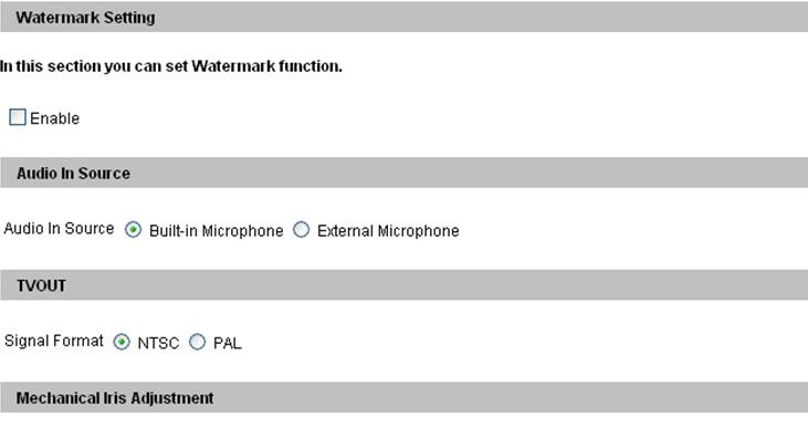
120 Overlaid with camera name: Includes streaming names on live and recorded videos. Overlaid with date stamps: Includes date stamps on live and recorded videos. Overlaid with time stamps: Includes time stamps on live and recorded videos. Overlaid with digital input description: Includes the name of the selected input on live and recorded videos. [Watermark Setting] Enable this option to watermark all recordings. The watermark allows you to verify whether the video has been tampered while it was recorded. See 11.4 Verifying Watermark. [Audio In Source] This function is only available in BX110D, PT110D and PTZ010D which contain a built-in microphone and also allow you to install an external microphone. Built-in Microphone: Enable the built-in microphone to record sounds. By default the option is enabled. External Microphone: Enable the externally connected microphone to record sounds. [TVOut] Note this function is only available for Box Camera. Select the signal format of the Video Output (No. 7, Figure 2-1) on the camera in either NTSC or PAL. 110
121 9 Administrator Mode [Mechanical Iris Adjustment] Auto adjustment: The option is designed for auto iris lens (DC drive). Click Start to automatically adjust the auto iris lens and bring exposure to optimum. For the first-time user of auto iris lens, you must enable this option to make adjustment for the lens and re-log on to the camera. [Special View Setting] D/N: Select Auto that will let the camera switch automatically to monochrome images in a poorly-lit scene. You can also switch either Black and White or Color images manually. IR Check Function: The option is designed to determine if the surveillance area is illuminated by the infrared light (from an infrared illuminator) or by sunlight. By the checking mechanism, the built-in IR cut filter can then work correctly with the D/N function. At night, the IR cut filter turns on to filter the infrared light and the image is switched to monochrome to produce better images. At day time, the IR cut filter turns off and the image is switched to color. Indoor: The default setting. The IR Check Function is enabled in this setting. Outdoor: The IR Check Function is disabled. It is suggested to enable this option when the color temperature of outdoor lighting is 6000 K or above. Triggered by Input: The D/N and IR Check functions are controlled by an input device connected to the camera, such as an infrared illuminator or timer. Note: If an infrared illuminator is installed for outdoor surveillance, it is suggested to use the Triggered by Input function to avoid the wrong judgment of lighting and the incorrect action of the IR cut filter. See Infrared Illuminators. 111
122 Auto Iris: The option is designed for auto iris lens (DC drive). Enable the auto iris function when the scene appears fuzzy and the Flicker Less function does not help to improve the situation. 112

123 9 Administrator Mode Motion Detection Motion detection is used to generate an alarm whenever movement occurs in the video image. You can configure up to 8 areas with different sensitivity values for motion detection. Figure The default sensitivity value for the whole area is 2. To define a different sensitivity value, click Reset. 2. Select the desired sensitivity by moving the slider. There are three values. The higher the value, the more sensitive the camera is to motion. 3. Drag an area on the image. Click Add when you are prompted to confirm the setting. 4. To create several areas with different sensitivity values, repeat Steps 2 and Click Save to save the above settings. 6. If you want to trigger the alarm output when motion is detected, select Output 1 and click the Apply button. To activate the output settings, you must also start Input monitoring manually or by schedule. For related settings, see 9.4 Monitoring. 113
, and for anywhere else you don t want sensitive information visible. Figure 9-4 1. Select the Enable option. 2.")
124 9.1.3 Privacy Mask The Privacy Mask can block out sensitive areas from view, covering the areas with dark boxes in both live view and recorded clips. This feature is ideal for locations with displays, keyboard sequences (e.g. passwords), and for anywhere else you don t want sensitive information visible. Figure Select the Enable option. 2. Drag the area(s) where you want to block out on the image. Click Add when you are prompted to confirm the setting. 3. Click the Save button to save all the settings. 114


125 9 Administrator Mode Text Overlay Note this function is only available in Box Camera, Mini Fixed Dome and Bullet Camera. The Text Overlay allows you to type any text in any place on the camera view. Up to 16 text messages can be created on one camera view. The overlaid text will be saved in the recordings. Figure Select the Enable option. 2. Click any place on the image. This dialog box appears. Figure Type the desired text, and click OK. The text is overlaid on the image. 4. Click on the text and drag it to any place on the image. 5. Click Set Font to modify the font style of the text. 6. Click Save to apply the settings, or click Load (Undo) to revert to a previous setting. 115

126 9.1.5 Tampering Alarm Note this function is only available for Box Camera, Mini Fixed Dome and Bullet Camera. The Tampering Alarm is used to detect when a camera is being physically tampered. An alarm can be generated when the camera is moved, covered up, or out of focus. The alarm approaches include the triggered output device and alert. To have the tampering alarm, first set up these alarm approaches properly: To trigger the output device when a tampering event occurs, enable the output setting and select Tampering Alarm. See Output Settings. To trigger the alert when a tampering event occurs, enable the setting and select Tampering Alarm. See Figure
127 9 Administrator Mode To configure the tampering alarm: 1. Select the Enable option. 2. If you want the camera to ignore any movement or scene change in certain areas, click the button to drag areas on the camera view. 3. Select the desired detection sensitivity by moving the slider. The higher the value, the more sensitive the camera is to scene changes. 4. In the Tolerance Time of Alarm field, specify the time length allowed for scene changes before an alarm is generated. 5. In the Duration of Alarm field, specify the duration of the alarm after which the triggered output device will be turned off. 6. To trigger an alarm when the scene turns dark, e.g. the lens of camera has been covered, select Alarm for Dark Images. 7. Click Apply to save all the settings. 8. Start monitoring to enable the function. To have output alarm, it is required to start Input monitoring. See 9.4 Monitoring. When the camera has been tampered, the output device can be activated. To turn off the output device immediately, return to this setting page, and click Restart Detection. 117


128 9.1.6 Visual Automation Note this function is only available for Box Camera and Bullet Camera. This intuitive feature helps you automate any electronic device by triggering the connected output device. When you click on the image of the electronic device, you can simply change its current state, e.g. light ON. Figure Select the Enable option. 2. Drag an area on the image of the electronic device. This dialog box appears. Figure Assign the connected module and output device. In the Note field, type a note to help you manage the device. Click OK to save the settings. 4. To change the frame color of the set area, click the Set Color button. 5. To emboss the set area, select Float Up; or keep it flat by selecting Normal. 6. Click the Save Set button to apply the settings. 7. To perform the function, see Visual Automation. 118
129 9 Administrator Mode 9.2 I/O Settings Note the I/O function is only available for Box Camera, Bullet Camera, PTZ Camera and PT Camera. After installing the I/O device, you need to enable the I/O settings on the camera. For how to install the I/O device on the camera, see the following reference sections: GV-IPCAM H.264 Box Camera Bullet Camera PTZ Camera PT Camera Reference section 2.7 I/O Terminal Block Connecting to the Data Cable 5.6 I/O Terminal Block 6.6 I/O Terminal Block Input Settings To activate the sensor input, select Enable. Figure
130 Normal State: You can set the input state to trigger actions by selecting Open Circuit (N/O) or Grounded Circuit (N/C). Latch Mode: Enable this option to have a momentary output alarm. Trigger digital output relay: When this option is enabled, the output will be triggered once the input is activated. Record: Enable this option to start recording when the input is triggered. Send Video to Center V2: Enable this option to send the images to Center V2 when the input is triggered. PTZ Settings: Note this function is only available for PTZ Camera and PT Camera. Input On: Select a preset point to which the camera turns when an input is triggered. Input Off: Select a preset point to which the camera returns when the input triggering is off. Duration to set preset after input off: Specify the duration that the camera stays at the Input On point before returning to the Input Off point. Note: 1. The Box Camera (BX110D) only supports the wet-contact input device (7V~30V). The Box Camera (BX120D/BX220D/BX320D), Bullet Camera, PTZ Camera and PT Camera support dry-contact input device. 2. The functions triggering the output, starting the recording when the input is triggered and sending video to Center V2 only work after you start Input monitoring manually or by schedule. To configure the input monitoring, see 9.4 Monitoring. 120
131 9 Administrator Mode Output Settings Select Enable to start the output device. Choose the output signal that mostly suits the device you are using: N/O (Open Circuit), N/C (Grounded Circuit), N/O Toggle, N/C Toggle, N/O Pulse or N/C Pulse. For Toggle output type, the output continues to be triggered until a new input trigger ends the output. For Pulse output type, the output is triggered for the amount of time you specify in the Trigger Pulse Mode for x Seconds field. [Alarm Settings] You can choose to automatically trigger the digital output under these conditions: tampering alarm (not available for PTZ Camera and PT Camera), disk write error (Rec Error) and hard disk full (HD Full). Figure
132 9.2.3 PTZ Settings Note this function is only available in PTZ Camera and PT Camera. You can change the image settings, configure sequences, and access settings including autopan speed, motor reset, digital zoom and system default loading. For details, see Accessing the VISCA OSD Configuration in PTZ Camera Settings. Figure
133 9 Administrator Mode 9.3 Events and Alerts For the events of motion detection or I/O trigger, the Administrator can set up two trigger actions: 1. Send a captured still image by or FTP. 2. Notify Center Monitoring Station, Center V2 or VSM, by video or text alerts. To have the above trigger actions, you must set the following functions in advance: Motion Detection (See Motion Detection)---Optional Input Setting (See Input Setting) For and FTP alerts, it is required to start monitoring (See 9.4 Monitoring). Note: The Motion Detection function is an optional setting since it is activated by default. 123
134 After a trigger event, the camera can send the to a remote user containing a captured still image. Figure 9-13 [Enable] Select to enable the function. Sever URL/IP Address: Type the URL address or IP address of the SMTP Server. Server Port: Modify the port number of the SMTP Server. Or keep the default value 25. From address: Type the sender s address. Send to: Type the address(s) you want to send alerts to. Alerts Interval Time: Specify the interval between alerts. The interval is between 0 and 60 minutes. The option is useful for the frequent event occurrence, by which any event triggers during the interval period will be ignored. 124
135 9 Administrator Mode [Need authentication to login] If the SMTP Server needs authentication, enable this option and type a valid username and password to log in the SMTP server. [ Alarm Settings] You can choose to automatically send an alert under these conditions: tampering alarm (not available for PTZ and PT Camera), disk write error (Rec Error), hard disk full (HD Full) and motion detection. For the related settings to send alerts, see Motion Detection, Input Setting and 9.4 Monitoring. 125
136 9.3.2 FTP You can also send the captured still image to a remote FTP server for alerts. Figure 9-14 [Upload to an FTP Server] Enable: Select to enable the FTP function. Server URL/IP Address: Type the URL address or IP address of the FTP Server. Server Port: Type the port number of the FTP Server. Or keep the default value 21. User Name: Type a valid username to log into the FTP Server. Password: Type a valid password to log into the FTP Server. Remote Directory: Type the name of the storage folder on the FTP Server. 126
137 9 Administrator Mode Alerts Interval time in minute: Specify the interval between FTP alerts. The interval can be between 0 and 60 minutes. The option is useful for the frequent event occurrence by which any event triggers during the interval period will be ignored. [Alarm Settings] Motion Detection: When a motion is detected on the camera, a still image will be sent to the FTP Server. Continuously send images upon trigger events (motion): A sequence of snapshots is uploaded to the FTP Server when a motion is detected. This stops as soon as no motion is detected. Digital Input: For Box Camera, PTZ Camera and PT Camera only. Once the input is triggered, a still image will be sent to the FTP Server. Continuously send images upon trigger events (input): A sequence of snapshots is uploaded to the FTP Server when the input is triggered. [Act as FTP Server] Enable FTP access to the GV-IP Cam: The camera acts as a FTP server, enabling users to download AVI files. Use alternative port: The default port is set to 21. To access the internal FTP server through a web browser, enter the IP address or the domain name of the camera in your browser like this: ftp:// When you are prompted for Username and Password, enter the default value ftpuser in both fields. Then you should find the AVI files recorded after trigger events. To change login information of the internal FTP server, see User Account. For related settings to send FTP alerts, see Motion Detection, Input Settings and 9.4 Monitoring. 127
138 9.3.3 Center V2 After a motion or an I/O triggered event, the central monitoring station Center V2 can get notified by live videos and text alerts. For the live monitoring through Center V2, you must already have a subscriber account on Center V2. A camera can connect to up to 2 Center V2 stations simultaneously. Figure
139 9 Administrator Mode To enable the Center V2 connection: 1. Activate Link: Enable the monitoring through Center V2. 2. Host Name or IP Address: Type the host name or IP address of Center V2. 3. Port Number: Match the port to the Port 2 value on Center V2. Or keep the default value User Name: Type a valid username to log into Center V2. 5. Password: Type a valid password to log into Center V2. 6. Click Apply. The Connection Status should display Connected and connected time. You can also find the following options on this Center V2 setting page: Cease motion detection messages from: Stops notifying Center V2 of motion-triggered events. Cease input trigger messages from: For Box Camera, PTZ Camera and PT Camera only. Stops notifying Center V2 of input-triggered events. Enable schedule mode: Starts the monitoring through Center V2 based on the schedule you set in the Select Schedule Time section. Refer to 9.5 Recording Schedule for the same settings. For related settings to activate the monitoring through Center V2, see Motion Detection, Input Setting, and 13.1 Center V2. 129
140 9.3.4 VSM After a motion or an I/O triggered event, the central monitoring station VSM can get notified by text alerts. For the monitoring through VSM, you must already have a subscriber account on VSM. A camera can connect up to 2 VSM simultaneously. Figure 9-16 To enable the VSM connection: 1. Activate Link: Enable the monitoring through VSM. 130
141 9 Administrator Mode 2. Host Name or IP Address: Type the host name or IP address of VSM. 3. Port Number: Match the port to the Port 2 value on VSM. Or keep the default value User Name: Type a valid username to log into VSM. 5. Password: Type a valid password to log into VSM. 6. Click Apply. The Connection Status should display Connected and connected time. These options you can also find on this VSM setting page: Cease motion detection messages from: Stops notifying VSM of motion-triggered events. Cease input trigger messages from: For Box Camera, PTZ Camera and PT Camera only. Stops notifying VSM of input-triggered events. Enable schedule mode: Starts the monitoring through VSM based on the schedule you set in the Select Schedule Time section. Refer to 9.5 Recording Schedule for the same settings. For related settings to activate the monitoring through VSM, see Motion Detection and Input Settings, and 13.2 VSM. 131
142 9.3.5 Backup Center Note this function is only available for Box Camera and Bullet Camera. The connection to the GV-Backup Center allows you to back up another copy of recordings and system log to the GV-Backup Center while the camera is saving these data to the memory card. Figure
143 9 Administrator Mode To enable the GV-Backup Center connection: 1. Activate Link: Enable the connection to the GV-Backup Center. 2. Host Name or IP Address: Type the host name or IP address of the GV-Backup Center. 3. Port Number: Match the communication port on the GV-Backup Center. Or keep the default value User Name: Type a valid username to log into the GV-Backup Center. 5. Password: Type a valid password to log into the GV-Backup Center. 6. Set Update Frequency: Set a duration time to check new video files from the camera and upload them to the GV-Backup Center. 7. Enable Schedule Mode: This setting is optional. Enable the GV- Backup Center connection on the schedule you set in the Select Schedule Time section. Refer to 9.5 Recording Schedule for the same settings. 8. Click Apply. The Connection Status should display Connected and connected time. If the GV-Backup Center has a failover server providing the uninterrupted backup services in case of the primary GV-Backup Center failure, you can configure the connection to the failover server. 1. Automatic Failover Support: Enable the automatic connection to the failover server once the connection between the camera and GV- Backup Center is interrupted for the specified time. 2. Host Name or IP Address: Type the host name or IP address of the failover server. 3. Port Number: Match the communication port on the failover server. Or keep the default value User Name: Type a valid username to log into the failover server. 5. Password: Type a valid password to log into the failover server. 6. Click Apply. 133
144 9.3.6 ViewLog Server Note this feature is only available for Box Camera, Bullet Camera, PTZ Camera and PT Camera. The ViewLog Server is designed for remote playback function. This server allows you to remotely access the recorded files saved at the GV-IPCAM H.264 and play back video with the ViewLog player. Select Enable to activate the built-in server. Keep the default port 5552 or modify it if necessary. For details on the remote playback, see Playback over Network. Figure
145 9 Administrator Mode GPP The 3GPP Server enables video and audio streaming to your 3G-enabled mobile phone. Figure 9-19 Activate Link: Enable the 3GPP service. RTSP/TCP Port: Keep the default value 8554, or modify it if necessary. RTP/UDP Port: Keep the default range from to 17319, or modify it if necessary. The number of ports for use is limited to 20. Max Connection: Set the maximum number of connections to the GV-IPCAM H.264 through 3GPP. The maximum value is 10. For details on remote monitoring with mobile phones, see Chapter 13 Mobile Phone Connection. 135
146 9.4 Monitoring You can start monitoring manually, by schedule or by input trigger. Note: See Note for Recording at the beginning of the manual. Figure 9-20 [Manual] Manually activates motion detection and I/O monitoring. Select one of the following options and then click the Start button. Select all: Manually starts both motion detection and I/O monitoring. Camera: Manually starts recording. Select the desired recording mode for recording. Input (for Box Camera, PTZ Camera and PT Camera Only): Manually starts I/O monitoring. When the sensor input is triggered, its associated camera and output will be activated for recording and alerting. For this setting, see Input Setting. [Schedule] The system starts motion detection and I/O monitoring according to the schedule you have set. For schedule settings, see 9.5 Recording Schedule. 136
147 9 Administrator Mode [Camera Status Icon] : On standby : Enabled for motion detection and input trigger 137
148 9.5 Recording Schedule The schedule is provided to activate recording and I/O monitoring on a specific time each day Recording Schedule Settings You can set the schedule for recording. Figure 9-21 Span 1- Span 3: Set a different recording mode for each time frame during the day. Each day can be divided into 3 time frames, represented by Span 1 to Span 3. Weekend: Enable this option to start monitoring all day on the weekend and select the recording mode to be used. Define whether your weekend includes Saturday and Sunday or Only Sunday. Special Day: Set the recording mode on a specified day. 138
149 9 Administrator Mode I/O Monitoring Settings Note this function is only available for Box Camera, Bullet Camera, PTZ Camera and PT Camera. You can set the schedule for I/O monitoring to start. Figure 9-22 Span 1- Span 3: Set different time frames during the day to enable I/O monitoring. Each day can be divided into 3 time frames, represented by Span 1 to Span 3. Weekend: Enable this option to start I/O monitoring all day on the weekend and define whether your weekend includes Saturday and Sunday or Only Sunday. Special Day: Enable I/O monitoring on a specified day. Note: In Recording Schedule and I/O Monitoring Schedule, if the settings for Special Day conflict with those for Span 1-3 or Weekend, the Special Day settings will get the priority. 139
150 9.6 Remote ViewLog Note this function is only available for Box Camera, Bullet Camera, PTZ Camera and PT Camera. With the Remote ViewLog function, you can play back the files recorded at the GV-IPCAM H.264 over TCP/IP network. For the first-time user, you need to install the Remote ViewLog program from the Software DVD. For remote access to the camera, the ViewLog Server built in the unit must be enabled. See ViewLog Server. For details on connecting to the camera for playback, see Playback over Network. 140
151 9 Administrator Mode 9.7 Network The Network section includes some basic but important network configurations that enable the camera to be connected to a TCP/IP network LAN According to your network environment, select among Static IP, DHCP and PPPoE. Figure
152 [LAN Configuration] Dynamic IP address: The network environment has a DHCP server. This option should only be enabled if you know which IP address the camera will get from the DHCP server, or you have obtained a domain name from the DDNS service provider that always links to the camera s changing IP address. Static IP address: Assign a static IP or fixed IP to the camera. Type the camera s TCP/IP and DNS parameters in the Configure connection parameters section. PPPoE: The network environment is xdsl connection. Type the Username and Password provided by ISP to establish the connection. If you use the xdsl connection with dynamic IP addresses, first use the DDNS function to obtain a domain name linking to the camera s changing IP address. [Configure connection parameters] Type the camera s IP address, Subnet Mask, Router/Gateway, Primary DNS server and Secondary DNS server. Parameters Default IP address Subnet Mask Router/Gateway Primary DNS server Secondary DNS server For details on Dynamic DNS Server Settings, see Advanced TCP/IP. 142
153 9 Administrator Mode Advanced TCP/IP This section introduces the advanced TCP/IP settings, including DDNS Server, HTTP port, streaming port and UPnP. Figure 9-24 [Dynamic DNS Server Settings] DDNS (Dynamic Domain Name System) provides a convenient way of accessing the camera when using a dynamic IP. DDNS assigns a domain name to the camera, so that the Administrator does not need to go through the trouble of checking if the IP address assigned by DHCP Server or ISP (in xdsl connection) has changed. 143
154 Before enabling the following DDNS function, the Administrator should have applied for a Host Name from the DDNS service provider s website. There are 2 providers listed in the camera: GeoVision DDNS Server and DynDNS.org. To enable the DDNS function: 1. Enable: Enable the DDNS function. 2. Service Provider: Select the DDNS service provider you have registered with. 3. Host Name: Type the host name used to link to the camera. For the users of GeoVision DDNS Server, it is unnecessary to fill the field because the host name will be detected and brought up automatically. 4. User Name: Type the username used to enable the service from the DDNS. 5. Password: Type the password used to enable the service from the DDNS. 6. Click Apply. [HTTP Port Settings] The HTTP port enables connecting the camera to the web. For security integration, the Administrator can hide the server from the general HTTP port by changing the default HTTP port of 80 to a different port number within the range of 1024 through [GV-IPCAM Streaming Port Settings] The VSS port enables connecting the camera to the GV-System. The default setting is [UPnP Settings] UPnP (Universal Plug & Play) is a networking architecture that provides compatibility among networking equipment, software and peripherals of the 400+ vendors that are part of the Universal Plug and Play Forum. It means that they are listed in the network devices table for the operating system (such as Windows XP) supported by this function. Enabling this function means you can connect to the camera directly by clicking on the camera listed in the network devices table. 144

155 9 Administrator Mode IP Filter Settings The Administrator can set IP filtering to restrict access to the camera. Figure 9-25 To enable the IP Filter function: 1. Enable IP Filtering: Enable the IP Filter function. 2. Filtered IP: Type one IP address or a range of IP addresses you want to restrict the access. 3. Action to take: Select the action of Allow or Deny to be taken for the IP address(es) you have specified. 4. Click Apply. 145
156 9.8 Management The Management section includes the settings of data and time and user account. You can also view the firmware version and execute certain system operations Date & Time Settings The date and time settings are used for date and time stamps on the image. Figure
157 9 Administrator Mode [Date & Time on GV-IP Camera] Displays the current date and time on the camera. [Time Zone] Sets the time zone for local settings. Select Enable Daylight Saving Time to automatically adjust the camera for daylight saving time. Type the Start Time and End Time to enable the daylight saving function. Also see Playback of Daylight Saving Time Events. [Synchronized with a Network Time Server] By default, the camera uses the timeserver of time.windows.com to automatically update its internal clock every 24 hours. You can change the host name or IP setting to the timeserver of interest, and specify a time for time update. [Synchronized with your computer or modify manually] Manually changes the camera s date and time. Or, synchronize the camera s date and time with those of the local computer. [Overlaid Date and Time Settings] Select the display format of date and time stamps on the image. For this function to work, you must also enable the Overlaid with date stamps and Overlaid with time stamps options in Figure

158 9.8.2 GPS Maps Settings The Maps Settings allows you to see the location of your GV-IPCAM H.264 on Google maps, without a GPS device. To see the location of your camera on maps: 1. It is required to sign up for a Google Maps API key before using the Google Maps. Click Link to the Google Maps API. Figure Enter the registered Maps API Key, the longitude and latitude of your camera, and location name. Click Apply to enable this function. 3. Open the control panel of the Live View window. Figure


159 9 Administrator Mode 4. Click Open. A warning message appears. Figure Right-click the warning message and select Allow Blocked Content. The map will be displayed. The icon indicates the location of your camera. At the upper right corner you have options to view different map formats, such as Satellite and Hybrid. Figure

160 9.8.3 Storage Settings Note this function is only available for Box Camera, Bullet Camera, PTZ Camera and PT Camera. Based on Linux ext3 file system, the GV-IPCAM H.264 supports memory cards for video and audio recordings. You need to format the memory card by using the following Storage Settings. After being formatted, the memory card will be ready to use by Linux OS of the camera. Figure 9-31 [Storage Settings] If Enable recycling is selected, when the space of the storage device is lower than the specified space, the system will overwrite the oldest recorded files. If Enable recycling is not selected, the system will stop recording when the specified space is reached. [Keep days (1-255)] Specify the number of days to keep the files from 1 day to 255 days. When both Keep days and Enable recycling are selected, the system applies whichever condition comes first. For example, if the specified smallest amount of storage space comes earlier than the designated keep days, then recycle is applied first. 150
161 9 Administrator Mode [Disk Information] This section shows the details of the attached storage device. [Partition Information] This section shows the partition details of the attached storage device. To add a memory card: 1. Insert the memory card to the camera. 2. Click the Format button. 3. After the format is complete, the partition information will display. The maximum space for one partition is 200 GB. To remove a memory card: 1. Click the Remove button. 2. When you are prompted to ensure the action, click Yes. The page will be refreshed and the partition information will be cleaned. 3. Remove the memory card from the camera. Note: 1. If Enable Recycle is selected, the available space of the storage device must be higher than the space you specified at the Stop recording or recycle disk when free space of disk is smaller than x option. Otherwise no video will be recoded. 2. The recording data may be lost if you remove the USB mass storage device during recording. 3. If you do not remove the storage device properly, the data cannot be read in another computer. In this case, re-plug the storage device back to the camera. The system will repair the data automatically. When the system is repairing the data, the Remove field will display Repairing. 151

162 9.8.4 User Account You can change the login name and password of Administrator and Guest. The default Administrator login name and password are admin; the default Guest login name and password are guest. To allow a Guest user log in without entering name and password, select Disable authentication for guest account. Figure
163 9 Administrator Mode Log Information The log information contains dump data that is used by service personnel for analyzing problems. Figure

164 9.8.6 System Log Note this function is only available for Box Camera and Bullet Camera. The System Log records the events in the four types of logs: System Event, Monitoring Event, I/O Event and Login/Logout. With the System Log, you can search and obtain the detailed information of an event. To use the System Log, a memory card is required to insert to the camera. 1. For the first-time user of the System Log, first click Create to create a log database (access file) on the memory card. Figure 9-34 Note: If you have created the System Log on the memory card, clicking Create again will clean your System Log. 2. Select the log type System Event, Monitoring Event, I/O Event or Login/Logout from the left menu of the Web interface. 3. Specify the filtering criteria. For example, we want to know the login and logout information during a specific period of time. 154

165 9 Administrator Mode 4. Click Query. The filtering results may look like the figure below. Figure
![9.8.7 Tools You can execute certain system operations and view the firmware version. Figure 9-36 [Host Settings] Enter a descriptive name for the camera.](/docs-images/91/107652080/images/166-0.jpg "[Firmware Update] This field displays the firmware version of the camera. [System Settings] Load Default: Clicking the Load Default button to restore factory default settings.")
166 9.8.7 Tools You can execute certain system operations and view the firmware version. Figure 9-36 [Host Settings] Enter a descriptive name for the camera. [Firmware Update] This field displays the firmware version of the camera. [System Settings] Load Default: Clicking the Load Default button to restore factory default settings. After applying the default settings configure the camera s network setting again. 156
167 9 Administrator Mode Current Chipset Temperature inside the Camera: For Bullet Camera, PTZ Camera and PT Camera only. Displays the chipset temperature inside the camera. [Reboot] Clicking the Reboot button will make the camera perform software reset. 157
168 Chapter 10 Recording and Playback Note this chapter and the function is only available for Box Camera, Bullet Camera, PTZ Camera and PT Camera. The GV-IPCAM H.264 can record video and audio directly to the memory card. You can play back the recorded files on the GV-System or over the TCP/IP network. Note: See Note for Recording at the beginning of the manual Recording To enable the recording function: 1. Insert the memory card to the camera. See To add a memory card, Storage Settings. 2. If you like to set up the pre-recording, post-recording or audio recording, see Video Settings. 3. If you like to set up the schedule for video recording or I/O monitoring, see 9.5 Recording Schedule. 4. If you like to configure the areas and sensitivity values for motion detection, see Motion Detection. 5. If you want the recording to be triggered by input device, configure the operation of input device. See Input Settings. 6. To start recording and I/O monitoring, see 9.4 Monitoring. The camera will start recording in case of motion detection, I/O trigger, or during the scheduled time. 158

169 10 Recording and Playback 10.2 Playback These methods are available to play back the video files recorded at the GV-IPCAM H.264: Playback by using the memory card by connecting it directly to the GV-System through a memory card reader Playback by using the Remote ViewLog function over the TCP/IP network Playback by using the recorded files downloaded from built-in FTP Server Playback Using the Memory Card You can play back the files recorded at the GV-IPCAM H.264 by connecting the memory card to GV-System through a memory card reader. However, GV-System is run on Windows system while the files recorded at the GV-IPCAM H.264 is of Linux file system. To enable Windows to recognize the files, you need to install the program Ext2 Installable File System included on the Software CD. 1. Insert the Software CD, select IFS Drives and follow the onscreen instructions for installation. 2. Run IFS Drives from Control Panel, and assign the drive name(s) to each available partition in the storage device. Figure

170 3. Run ViewLog. 4. Click the Advanced button, select Reload Database and click Video Server/Compact DVR. This dialog box appears. Figure Click Add to assign the hard drive. 6. Click OK to load the data to the ViewLog for playback. 160

171 10 Recording and Playback Playback over Network With the Remote ViewLog function, you can play back the files recorded at the GV-IPCAM H.264 over TCP/IP network. 1. The camera needs to allow the remote access with ViewLog Server activated. See ViewLog Server. 2. For the first-time user, run the Remote ViewLog program from the Software CD. Next time whenever you like to use this function, access this option from the camera s Web interface. 3. When this dialog box appears, type the camera s IP address, login ID and password. Keep the default port 5552 or modify it if necessary. Figure In the Host Type field, select GV-IP Device. 5. Click Connect to access the files of the camera for playback. 161
172 Access to the Recorded Files through FTP Server The built-in FTP Server allows you to download the recorded files saved on the memory card. You can play back the downloaded files of AVI format with any multimedia player. For details to download files, see [Act as FTP Server], FTP Playback of Daylight Saving Time Events On GV-System, you can retrieve the events recorded during the Daylight Saving Time (DST) period from the GV-IPCAM H.264 for playback. You can also connect the memory card to GV-System for playback. The following instructions describe how to retrieve the recorded files from the GV-IPCAM H.264 over network. If you like to use the memory card for playback, first follow the instructions in Playback Using the Memory Card to load the recorded files to ViewLog, and then follow Steps 4-5 below to play back DST events. 1. The camera must allow the remote access with ViewLog Server activated. See ViewLog Server. 2. To remotely connect to the camera from GV-System, click the Tools button and select Remote ViewLog Service. The Connect to Remote ViewLog Service dialog box appears. 3. Enter the connection information of the camera, and click Connect. Once the connection is established, the video events will be displayed on the Video Event list. 162

173 10 Recording and Playback 4. On the Date Tree, select the date of Daylight Saving Time. A separate DST subfolder will be displayed as illustrated below. Figure On the Video Event list, select desired events, and click the Play button to start. Note: 1. The playback function is only compatible with the GV-System of version 8.3 and later. 2. The AVI file recorded during the DST period is named with the prefix GvDST, e.g. GvDST xxxxxxxxx.avi, to differentiate from the regular AVI file named with the prefix Event, e.g. Event xxxxxxxxx.avi. 163
174 Chapter 11 Advanced Applications This chapter introduces more advanced applications Upgrading System Firmware GeoVision will periodically release the updated firmware on the website. The new firmware can be simply loaded into the GV-IPCAM H.264 by using the Web interface or IP Device Utility included in the Software CD. Important Notes before You Start Before you start updating the firmware, please read these important notes: 1. While the firmware is being updated, A) the power supply must not be interrupted, and B) do not unplug the Ethernet cable if the cable is the source of power supply (Power over Ethernet or PoE supported). 2. Do not turn the power off within 10 minutes after the firmware is updated. 3. If you use the IP Device Utility for firmware upgrade, the computer used to upgrade firmware must be under the same network of the camera. WARNING: The interruption of power supply during updating causes not only update failures but also damages to the camera. In this case, please contact your sales representative and send your device back to GeoVision for repair. 164
, select Remote Config, and click the Firmware Upgrade tab. This dialog box appears. Figure 11-1 2. Click the Browse button to locate the firmware file (.")
175 11 Advanced Applications Using the Web Configuration Interface 1. In the Live View window, click the Show System Menu button (No. 8, Figure 8-3), select Remote Config, and click the Firmware Upgrade tab. This dialog box appears. Figure Click the Browse button to locate the firmware file (.img) saved at your local computer. 3. Click the Upgrade button to start the upgrade. 165

176 Using the IP Device Utility The IP Device Utility provides a direct way to upgrade the firmware to multiple units of GV-IPCAM H.264. Note the computer used to upgrade firmware must be under the same network of the camera. 1. Insert the Software CD, select IP Device Utility, and follow the onscreen instructions to install the program. 2. Double-click the IP Device Utility icon created on your desktop. This dialog box appears. Figure Click the Search button to locate available cameras on the same LAN. Or click the New button and assign the IP address to locate the camera over the Internet. Or highlight one camera in the list and click the Delete button to remove it. 166
177 11 Advanced Applications 4. Double-click one camera in the list. This dialog box appears. Figure Click the Firmware Upgrade tab. This dialog box appears. Figure Click the Browse button to locate the firmware file (.img) saved at your local computer. 7. If you like to upgrade all the cameras in the list, select Upgrade all devices. 8. Type Password, and click Upgrade to start the upgrade. 167

178 11.2 Backing Up and Restoring Settings With the IP Device Utility included in the Software CD, you can back up the configurations in the GV-IPCAM H.264, and restore the backup data to the current camera or import it to another camera. To back up the settings: 1. Run IP Device Utility and locate the desired camera. See Steps 1-3 in Using the IP Device Utility. 2. Double-click the camera in the list. Figure 11-3 appears. 3. Click the Export Settings button. This dialog box appears. Figure Click the Browse button to assign a file path. 5. Type Password, and click the Export Settings button to save the backup file. 168

179 11 Advanced Applications To restore the settings: 1. In Figure 11-3, click the Import Settings tab. This dialog box appears. Figure Click the Browse button to locate the backup file (.dat). 3. Select Upgrade all devices to import the settings into the same type of device in the same LAN. To import password settings and/or network settings, select Password Settings and/or Network settings. 4. Click the Update Settings button to start restoring. 169
180 11.3 Restoring to Factory Default Settings Please refer to the corresponding section of your camera type and follow the steps to restore factory default settings. Box Camera: GV-BX110D 1. Unplug the power cable and the network cable to start. 2. Press and hold the Default button (No. 4, Figure 2-1) on the back panel of the camera. 3. Plug the power cable. The status LED on the front panel of the camera turns red. 4. Wait until the status LED turns off. This may take about 10 seconds. 5. Soon after the status LED turns off, it turns red again and a clicking sound appears. Then you can release the Default button and the process of loading default values is complete. GV-BX120D / 220D / 320D 1. Unplug the power cable and the network cable to start. 2. Press and hold the Default button (No. 7, Figure 2-2) on the back panel of the camera. 3. Plug the power cable, or the network cable to power on the camera through the PoE adaptor. The status LED on the front panel of the camera turns on and then off twice. This may take about 30 seconds. 4. Release the Default button and the process of loading default values is complete. 170
181 11 Advanced Applications Mini Fixed Dome: 1. Unplug the network cable to start. 2. Unscrew the camera s cover. 3. Press and hold the Default button (No. 1, Figure 3-1). 4. Plug the network cable to power on the camera through the PoE adaptor. Wait until the network status LED turns off. This may take about 40 seconds. 5. Soon after the network status LED turns off, release the Default button. The process of loading default values is complete. Bullet Camera: 1. Unplug the power cable and the network cable to start. 2. Loosen the camera s cover and remove the Silica Gel Bag. 3. Unscrew the Fixing Screw and slightly pull out the camera module. See Figure Press and hold the Default button for 50 seconds while plugging the power cable. Figure Release the Default button and the process of loading default values is complete. 6. Slightly push the camera module back and fasten the Fixing Screw. 7. Replace a new Silica Gel Bag and fasten the camera s cover immediately. 171
182 PTZ and PT Camera There are two types of default settings: camera default settings and system default settings. Camera default settings include all settings on Iris, White Balance, Image Reverse and Other in the VISCA OSD Configuration dialog box (Figure 5-14). System default settings refer to all the settings of the PTZ / PT camera except the camera settings. To load camera default settings (only available in PTZ camera): 1. On the left menu of Web interface, select Digital I/O and PTZ, select PTZ Settings, and select System Configure. The VISCA OSD Configure dialog box appears. 2. Click the Load Camera Default button. Figure
183 11 Advanced Applications To load system default settings 1. Unplug the power cable or the network cable (if it is also used as the power supply). 2. Press and hold the Default button (No. 10, Figure 5-10). 3. Plug the power and network cable back. 4. Hold the Default button until the two network LEDs fade. This will take about 25 seconds. Figure When default loading is complete, the camera will pan and tilt to its full range and return to the home point. 173
184 11.4 Verifying Watermark The watermark is an encrypted and digital signature embedded in the video stream during the compression stage, protecting the video from the moment of creation. Watermarking ensures that an image is not edited or damaged after it is recorded. To enable the watermark function, see [Watermark Setting], Video Settings. The Watermark Proof is a watermark-checking program. It can verify the authenticity of the recording before you present it in court Accessing AVI Files To verify watermark, first you have to access the recorded AVI files by one of these methods: 1. Use the File Save function (No.6, Figure 8-3) to start recording on the local computer. 2. Use the Act as FTP Server function to download AVI files from the GV-IPCAM H.264. See FTP. 3. Use the files recorded on the memory card. Since the files saved on the memory card are of Linux file system, remember to run IFS Drives from the Software CD to convert the Linux-based files to Windows-based files. For the instructions, see Steps 1 to 2 in Playback Using the Memory Card. 174
185 11 Advanced Applications Running Watermark Proof 1. Install Watermark Proof from the Software CD. After installation, a WMProof icon is created on your desktop. 2. Double-click the created icon. The Water Mark Proof window appears. 3. Click File from the menu bar, select Open and locate the recording (.avi). The selected recording is then listed on the window. Alternatively, you can drag the recording directly from the storage folder to the window. 4. If the recording is unmodified, a check mark will appear in the Pass column. On the contrary, if the recording is modified or does not contain watermark during recording, a check mark would appear in the Failed column. To review the recording, double-click the listed file on the window. 175

186 The Watermark Proof Window The controls in the window: No. Name Figure Description 1 Open File Opens the recording. 2 First Frame Goes to the first frame of the file. 3 Play Plays the file. 4 Previous Frame Goes to the previous frame of the file. 5 Next Frame Goes to the next frame of the file Previous Watermarked Frame Next Watermarked Frame Original vs. Extracted Goes to the previous frame that contains watermark. Goes to the next frame that contains watermark. The Extracted icon should be identical with the Original icon. If not, it indicates the recording has been tampered. 9 File List Displays the proof results. 176
187 12 DVR Configurations Chapter 12 DVR Configurations The GV-System provides hybrid solution, integrating the digital videos from IP cameras with other analog videos. For the digital videos, the GV-System provides the complete video management, such as video viewing, recording, playback, alert settings and almost every feature of the system. Following is the integration specifications: IP Camera Box Camera Mini Fixed Dome Bullet Camera PTZ and PT Camera Compatible version of GV-System V8.3.2 or later V8.3.3 or later V8.4 or later V8.4 or later Figure
188 The maximum number of connections which the GV-IPCAM H.264 allows from the GV-System varies according to its type: GV-IPCAM H.264 Max. No. of Connections BX110D / M/FD110D / BL110D 7 BX120D 10 BX220D / 320D 7 When the GV-System connects to the GV-IPCAM H.264, it takes up to 2 connections. When the user connects to the GV-IPCAM H.264 via browser, it takes up to 2 connections. When the user operates the Camera/Audio Control on Center V2 to connect the GV-IPCAM H.264, it takes 1 connection. The codec and resolution of digital videos are set up on the GV-IPCAM H.264 instead of on the GV-System. The hardware compression and the Pre-Recording Using RAM feature cannot work on the videos from GV-IPCAM H


189 12 DVR Configurations 12.1 Setting up an IP Camera To set up the GV-IPCAM H.264 on the GV-System, follow these steps: 1. On the main screen, click the Configure button, select General Setting, select Camera / Audio Install and click IP Camera Install. This dialog box appears. Figure 12-2 To add an IP camera from a list of the IP cameras on the LAN, click Scan Camera. To manually set up an IP camera, follow steps 2 to 7 2. Click Add Camera. The dialog box appears. Figure

190 3. Type the IP address, username and password of the IP camera. Select the camera brand and device from the drop-down lists. This dialog box appears. Figure The GV-System will automatically query for the IP camera, and the status will be indicated as Standby. If not, modify the HTTP port (Figure 12-3) and streaming port (Figure 12-4) to match those of the IP camera, and click the Query button to detect the IP camera again. 180
191 12 DVR Configurations 5. The options in the setup dialog box may vary depending on the camera brand. Dual Stream: Click this button to set the codec type to H.264 in the main stream and to MPEG4 in the sub stream, but each stream with a different resolution. The table lists the availability of this function in firmware versions and the resolutions in different cameras. Camera Supported Firmware Version Resolution Main Stream Sub Stream (H.264) (MPEG4) BX110D MFD110D BL110D V1.05 V x x x x 256 BX120D V x x 256 BX220D V x x 252 BX320D V x x 240 PT110D V x x 256 PTZ010D-N V x x 240 PTZ010D-P V x x
192 Figure 12-5 Port: Video streaming port number. Stream Number: You may have the option of single streaming only or both single and dual streaming. Codec type: You may have the option of MPEG4, JPEG, or H.264. If the selected camera supports dual streaming, the preview codec and recording codec can be set differently. Resolution: Select resolutions for preview and recording. 6. Click Apply. The IP camera is added to the list. 182

193 12 DVR Configurations 7. Click the listed camera, and select Display position to map the IP camera to a channel on the GV-System. Figure The Status column now should display Connected. Click OK. 183
194 Previewing Video and Setting Audio To preview video and activate audio, make sure the IP camera is connected, right-click the desired IP camera on the connection list and select Preview & Audio Setting. This dialog box appears. Figure 12-7 [Preview selected camera] Drop-down List: Select the desired camera for live preview. Preview dual stream record channel: The option is only available when the dual stream is selected, i.e. the cameras for live view and recording are configured differently (Figure 12-4). Select this option for recording preview. 184
195 12 DVR Configurations [Audio Setting] Monitor Sensitivity: Adjust the sensitivity of the audio that will be detected. The higher the value, the more sensitive the system is to the surrounding sound. Gain Control: Increase or decrease the gain of the microphone. Round-the-Clock Audio: Select this option to activate non-stop audio recording. Wave Out: Select this option to listen to live audio from the IP camera. Rec Audio: Select this option to activate the audio recording. [Image Orientation] To change the image orientation, select among Normal, Horizontal Mirror, Vertical Flip and Rotate 180. [Hardware compressed data control] Hardware-compressed data from the video IP device, such as IP Camera, Video Server and Compact DVR, can be transmitted directly to remote servers instead of being compressed again on GV-System. The remote servers include Center V2, Control Center and WebCam. This function is useful when many remote servers access GV-System at one time. It can reduce the system load on GV-System, and provide more frame rates and better image quality for each remote server. Note: It is highly recommended to enable this function on a LAN environment because it requires a lot of bandwidth. [Live-view frame rate control] Set the frame rate of live view which can reduce the CPU usage. 185
196 Live-view key frame only: This option is available when the video codec of the IP camera is set to MPEG4 or H.264. You can choose to view the video of key frames instead of all frames on the live view. This option is related to the GOP setting of the IP camera. For example, if the GOP value is set to 30, there is only one key frame among 30 frames. For the GOP setting, see Video Settings. [Prerecording with GOP] Enable video recording before an event occurs. The number of frames the GV-System will prerecord is based on the GOP value set on the IP camera. To enable this function, the three requirements must be met: D1 or CIF resolution, the number of frames in GOP set to 60 or less than 60 frames, MPEG4 or H.264 codec. [GV-GIS Setting] Receive the GPS data from the IP device. To receive the GPS data, remember to also enable the GIS function of the GV-System (Configure button < Accessories < Enable Local GIS). 186

197 12 DVR Configurations 12.2 Remote Monitoring with Multi View You can use the Multi View to monitor and manage the GV-IPCAM H Connecting to the IP Camera 1. On the Multi View window, click the Edit Host button. The Edit Host window appears. 2. To create a host, click the New button. You need to create a group before creating a host. 3. Select GV-IP Camera, GV-IP Speed Dome from the Device dropdown list. Type the host name, IP address, user name and password of the camera. Modify the default VSS port if necessary. Figure Click Save to establish connection. For details on the Multi View functions, see Multi View Viewer, Remote Viewing, DVR User s Manual on the Surveillance System Software DVD. 187

198 12.3 Remote Monitoring with E-Map You can use the Remote E-Map to monitor and manage the GV-IPCAM H Creating an E-Map for the IP Camera With the E-Map Editor, you can create an E-Map for the GV-IPCAM H.264. The E-Map Editor is available in the two applications: Main System and E- Map Server. The following is an example of running the E-Map Editor included in the Main System. 1. Go to Windows Start menu, point to Programs, select GV folder and click E-Map Editor. 2. To create an E-Map, click the Add Map button on the toolbar. A New Map file appears. 3. Double-click the New Map file, and click the Load Map button on the toolbar to import a graphic file 4. To create a host, click the Add Host button on the toolbar and select Add IPCam. 5. Right-click the created New Host in the Host View, and select Host Settings. This dialog box appears. Figure Give the camera a location name, and type its IP address (or domain name). Modify the default VSS port if necessary. 188
199 12 DVR Configurations 7. Click OK to save the settings. 8. Expand the created host folder. Drag and drop the icons of camera and I/O devices onto the imported E-Map. 9. Close the E-Map Editor. Click Yes when you are promoted to save the file. For details on creating an E-Map file on the E-Map Server, see E-Map Server, E-Map Application, DVR User s Manual on the Surveillance System Software DVD Connecting to the IP Camera Depending on where you save the created E-Map file (DVR, E-Map Server or Control Center), the steps to open the Remote E-Map window for monitoring may vary slightly. The following is the connection example when you store the E-Map file on the DVR. 1. To enable the remote access to the DVR, click the Network button, select WebCam Server to display the Server Setup dialog box, and click OK to start the WebCam server. 2. At the local computer, open the web browser and type the address of the DVR. The Single View page appears. 3. Select Emap. A valid user name and password are required for login. For the first-time user, you will be directed to the Download page. Install the E-Map program before you can run it. 4. On the Remote E-Map window, click the Login button and select the camera host to access its videos and I/O devices. A valid user name and password are required to log in the camera. For details on the Remote E-Map functions, see The Remote E-Map Window, E-Map Application, DVR User s Manual on the Surveillance System Software DVD. 189
200 Chapter 13 CMS Configurations This section introduces the related settings to enable connecting to the GV- IPCAM H.264 in the central monitoring stations Center V2, VSM and Dispatch Server Center V2 The Center V2 can monitor and manage the camera and I/O devices connected to the GV-IPCAM H.264. TCP/ IP IP Camera Video Data Text Data Center V2 IP Camera Figure


201 13 CMS configurations To set the appropriate port connecting to the IP camera, click the Preference Settings button, select System Configure, click the Network tab, and select Accept connections from GV-Compact DVR, Video Server & IP Cam. Keep default port 5551, or modify it to match the Center V2 port on the IP camera. Figure 13-2 To define how to display the received video on motion detection and input trigger from the IP camera, click the Preference Setting button and select System Configure. This dialog box appears. Figure
202 Manual close channel: Closes the triggered camera view manually. Close the camera view when motion stopped: Closes the triggered camera view automatically when motion stops. Post Motion: Specify the duration of the camera view remaining on the monitoring window after a motion stops. Camera send by I/O trigger will monitor: Specify the duration of the camera view remaining on the monitoring window when an I/O device is triggered. To keep the camera view remaining on the monitoring window even after the alarm is finished, click the right-arrow button, and uncheck Latch Trigger. Then the camera view will keep remaining on the monitoring window for the specified time. For example, the alarm is triggered for 5 minutes and you set 10 minutes, which means the total display time will be 15 minutes. For further information on how to mange the video received from the IP camera, see GV-CMS Series User s manual. 192

203 13 CMS configurations 13.2 VSM The VSM can monitor and manage the camera and I/O devices connected to the GV-IPCAM H.264. TCP/ IP IP Camera Text Data VSM IP Camera Figure 13-4 To set the appropriate port connecting to the IP camera, click Configure on the window menu, and select System Configure to display this dialog box. In the Connective Port field, keep the default port 5609, or modify it to match the VSM port on the IP camera. Figure 13-5 For further information on how to mange the video received from the IP camera, see GV-CMS Series User s manual. 193
204 13.3 Dispatch Server The Dispatch Server can manage the camera and I/O devices connected to the GV-IPCAM H.264, and distribute them to the Center V2. TCP/ IP IP Camera Center V2 Video Data Text Data Dispatch Server IP Camera Center V2 Figure

205 13 CMS configurations To set the appropriate port connecting to the IP camera, click the Server Setting button on the toolbar, and select Allow GV IP devices to login as subscriber from port. Keep the default port as 5551, or modify it to match the Center V2 port on the IP camera. Figure 13-7 For further information on how to mange the video received from the IP camera, see GV-CMS Series User s manual. 195
206 Chapter 14 Mobile Phone Connection Using a PDA, Smartphone or 3G-enabled mobile phone, you can receive live video streaming from the GV-IPCAM H.264. The chart below lists the GV mobile applications supporting the GV-IPCAM H.264. Handheld Device View OS Supported Default Port Video Settings on GV-IPCAM H.264 GView V2 Windows Mobile 5.0 and 2003 for Pocket PC; Windows Mobile 6.0 / 6.1 Classic and Professional TCP/IP Port: RPB Port: 5552 (ViewLog Server) 3GPPv7, MSViewV2/V3, SSViewV3 and GViewV2 Supported MSView V2 Windows Mobile 5.0 and 2003 for Smartphone TCP/IP Port: RPB Port: 5552 (ViewLog Server) 3GPPv7, MSViewV2/V3, SSViewV3 and GViewV2 Supported MSView V3 Windows Mobile 6.0 / 6.1 Standard and Professional TCP/IP Port: RPB Port: 5552 (ViewLog Server) 3GPPv7, MSViewV2/V3, SSViewV3 and GViewV2 Supported SSView V3 Nokia S60 2nd Edition and 3rd Edition for Smartphone TCP/IP Port: RPB Port: 5552 (ViewLog Server) 3GPPv7, MSViewV2/V3, SSViewV3 and GViewV2 Supported 196
207 14 Mobile Phone Connection 3GPP Mobile phones with players supporting RTSP TCP/IP Port: 8554 UDP Port: Http Port: 80 3GPPv7, MSViewV2/V3, SSViewV3 and GViewV2 Supported Chart 1 Note: 1. For the 3G-enabled mobile phone, you can receive live video from the camera without installing any GV mobile applications. 2. To receive the live video from the camera, enter the TCP/IP port on your mobile phone. To play video back, enable ViewLog Server on the camera and enter the RPB Port on your mobile phone. 197
208 14.1 PDA GView V2 is a remote view application for Pocket PC device. It can run on the PDA with Windows Mobile operating system. For the supported operating system version, see Chart 1. When GView V2 detects the big screen panel of the mobile phone, images from the GV-IPCAM H.264 will be horizontally rotated for a better view. Resolution is set to be CIF by default Installing GView V2 GView V2 should be installed on a PDA device with Microsoft Windows Mobile operating system. 1. Download and install Microsoft PDA Viewer V2 from to the computer. 2. Follow the on-screen instructions to complete the installation. The default installation directory is C:\Microsoft PDA Viewer V2. 3. Through the synchronization program such as ActiveSync, install GViewV2.exe from the installation directory to your PDA. Consult your PDA user s manual for how to install a program to the PDA. 198
209 14 Mobile Phone Connection Activating the GView Function To allow remote access to the GV-IPCAM H.264, you must select 3GPPv7, MSViewV2/V3, SSViewV3 and GViewV2 Supported to be the connection type in the Connection Template field on the Video Settings page. See Connection Template in Video Settings for details. Figure
210 Connecting to the IP Camera Once GView V2 is installed on your PDA, you can use it to monitor your GV-IPCAM H.264. Make sure your PDA has wireless LAN adapter properly in place with access to the Internet. 1. Execute GView V2 on your PDA. Figure
, a username and a password. Then click OK. 4.")
211 14 Mobile Phone Connection 2. Click the button located at the lower left corner. The login screen appears. Figure Enter the IP address of your camera, port value (default value is 10000), a username and a password. Then click OK. 4. Once the connection is established, the live image will appear. 201
.")
212 Playing Back the Recordings from the IP Camera To play back the recordings from the GV-IPCAM H.264, follow these steps: 1. Enable the ViewLog Server on the camera. Keep the connection port to be 5552 or modify it if necessary. See ViewLog Server for details. 2. Execute GView V2 in your PDA. 3. Click the button located at the lower left corner Figure 14-2). The login screen appears. Figure Enter the IP address of your GV-IP Camra, port value (default value is 5552), a username and a password. Then click OK to connect. 5. Select the desired video recording from the event list for playback. 202
213 14 Mobile Phone Connection Other Functions In addition to live view and playback, GView V2 offers these functions: viewing / controlling I/O devices, PTZ control, adjusting image quality, and starting / stopping recording. On the live view screen, click the buttons on the toolbar to have the desired functions. Figure 14-5 Button Description Click it to stop the connection. Click it for Focus-in / Focus-out and Zoom-in / Zoom-out control. This is only available when the camera supports PTZ functions. Click it to move the camera to different directions. This is only available when the camera supports PTZ functions. Click it to move the camera to the preset positions. This is only available when the camera supports PTZ functions. Click it to adjust the image quality. Click it to access the connected I/O devices. 203

214 Click it to start or stop recording. Click it to display the camera status. The supervisor is given the highest priority to control the PTZ camera and is not restrained by the 60-second time limit. When the supervisor logs in, the Timer shows 999. Use this drop-down list to switch cameras. Accessing I/O Devices To access the connected I/O devices, use the drop-down list to select the desired camera and click the button. The I/O module button appears on the toolbar. Figure 14-6 The numbers on the toolbar indicate the connected module. Click the desired number to access its I/O devices. The I/O control buttons appear on the toolbar. 204

215 14 Mobile Phone Connection Figure 14-7 Button I O Description Click it to view the log of input triggers. Click it to display and force the connected output devices. Viewing Input-Triggered Events All input triggers are logged on the Alarm list. Click the I button to view the list of trigger events. Figure
216 Forcing Outputs To force any connected output devices, click the O button to, and click the desired number. The numbers on the toolbar indicate the connected output devices. Figure 14-9 Controlling PTZ Cameras To control the PTZ camera, use the drop-down list to select the desired camera, and click the button on the live view screen (Figure 14-5). Figure
. button on the live view screen Figure 14-11 This screen displays the status of camera activity.")
217 14 Mobile Phone Connection Button Description Click it to return to the previous page. Use these buttons to move the PTZ camera to the left, up, down and right Click it to return to home. Viewing Camera Status To view the camera status, click the (Figure 14-5). button on the live view screen Figure This screen displays the status of camera activity. Three messages indicate the current camera status. Message Normal Inactive Recording Description The camera is turned on and not recording. The camera is turned off. The camera is recording. 207
218 14.2 Windows Smartphone With the MSView application, you can monitor your GV-IPCAM H.264 remotely through a Windows-based Smartphone. For the supported operating system version, see Chart Installing MSView V2 / V3 1. Download and install Microsoft Smartphone Viewer V2 or Microsoft Smartphone Viewer V3 from to the computer. 2. Follow the on-screen instructions to complete the installation. The default installation directory is C:\SmartPhone Viewer V2 or C:\SmartPhone Viewer V3. 3. Through the synchronization program such as ActiveSync, install MsviewV2.exe or MsviewV3.exe from the installation directory to your Smartphone. Consult your Smartphone user s manual for how to install a program to the Smartphone. 208
219 14 Mobile Phone Connection Activating the MSView V2 / V3 Function To allow remote access to the GV-IPCAM H.264, you must select 3GPPv7, MSViewV2/V3, SSViewV3 and GViewV2 Supported to be the connection type in the Connection Template field on the Video Settings page. See Connection Template in Video Settings for details. Figure

220 Connecting to the IP Camera The following operations may vary slightly for different modules. 1. Execute MSViewV2.exe or MSViewV3.exe on your Smartphone. Figure Click Type and then Live. Figure


221 14 Mobile Phone Connection 3. On the login screen, enter the IP address of your camera, port value (default value is 10000), a username and a password. Then click Control and select Connect. Figure Once the connection is established, the live image will appear. You can use the scroll key on your Smartphone to navigate camera channels. Figure
222 Playing Back the Recordings from the IP Camera To play back the recordings from the GV-IPCAM H.264, follow these steps: 1. Enable ViewLog Server on the camera. Keep the connection port to be 5552 or modify it if necessary. See ViewLog Server for details. 2. Execute MSView V2 or MSView V3 in your Smartphone. 3. Select Type and then Rpb (Figure 14-14). The login screen appears. If you want to search the recordings within a specific period of time for playback, select Rpb with time. Figure Enter the IP address of your camera, port value (default value is 5552), a username and a password. Then click Select and click GV Video Server to start the connection. 5. Select the desired video recording from the event list for playback. 212
223 14 Mobile Phone Connection Other Functions In addition to live view, MSView V2 or MSView V3 offers these functions: zooming in/out a camera view, rotating images and controlling outputs. Select the Control option to have these features Symbian Smartphone With the SSView V3 application, it s also possible to monitor your GV- IPCAM H.264 remotely through a Symbian-based Smartphone. For the supported operating system version, see Chart Installing SSView V3 To install SSView Version 3 for Nokia S60 2nd and 3rd Edition: 1. Download and install Symbian Smartphone Viewer V3 from to the computer. 2. Follow the on-screen instructions to complete the installation. The default installation directory is C:\Symbain SmartPhone Viewer V3. 3. Through the synchronization program such as Nokia PC Suite, install SSviewV3.exe from the installation directory to your Smartphone. Consult your Smartphone user s manual for how to install a program to the Smartphone. 213
224 Activating the SSView V3 Function To allow remote access to the GV-IPCAM H.264, you must select 3GPPv7, MSViewV2/V3, SSViewV3 and GViewV2 Supported to be the connection type in the Connection Template field on the Video Settings page. For details, see Connection Template in Video Settings. Figure

, a username and a password.")
225 14 Mobile Phone Connection Connecting to the IP Camera The following operations may vary slightly for different modules. 1. Execute SSView on your Smartphone. 2. When the message SSView V3 appears, select Options, and select Live Connect. The login screen appears. Figure Enter the IP address of your camera, port value (default value is 10000), a username and a password. Then click Options and select Connect. 4. Once the connection is established, the live image will appear. Figure

226 Quick Connection The IP addresses of connected servers can be stored for quick connection in the future. Press the [<] and [>] buttons on the mobile device to select the desired camera for connection Playing Back the Recordings from the IP Camera To play back the recordings from the GV-IPCAM H.264, follow these steps: 1. Enable ViewLog Server on the camera. Keep the connection port to be 5552 or modify it if necessary. See ViewLog Server for details. 2. Execute SSView on your Smartphone. 3. When the message SSView V3 appears, click Options, and then select Rpb. The login screen appears. If you want to search the recordings within a specific period of time for playback, select Rpb With Time. Figure
227 14 Mobile Phone Connection 4. Enter the IP address of your camera, port value (default value is 5552), a username and a password. Then click Options and select Video Server. 5. Select the desired video recording from the event list for playback Other Functions In addition to live view, SSView offers these functions: changing camera channels, zooming in a camera view, rotating images and controlling outputs. Select Options to have these features. 217

228 14.4 3G Mobile Phone Without installing any GV applications, you can use a 3G mobile phone to access GV-IPCAM H.264 directly Activating the 3G Mobile Phone Function To allow remote access to the GV-IPCAM H.264, follow the steps below: 1. Select 3GPPv7, MSViewV2/V3, SSViewV3 and GViewV2 Supported to be the connection type in the Connection Template field on the Video Setting page. Figure Enable the 3GPP Server on the camera. See GPP for details. Figure


229 14 Mobile Phone Connection Connecting to the IP Camera 1. Open the Internet browser in the mobile phone, and enter the IP address of your camera, a user name and a password. Then click Apply to connect. Figure After the connection is established, an image similar to this example appears. Figure

230 3. Select the desired channel. Its live image will appear. Figure Note: Currently the 3GPP application does not support remote playback and I/O control. 220
231 Specifications: Box Camera Specifications: Box Camera Camera Image Sensor Picture Elements GV-BX110D GV-BX120D GV-BX220D GV-BX320D GV-BX110D GV-BX120D GV-BX220D 1/3" progressive scan CMOS 1/2.5 progressive scan CMOS 1280 (H) x 1024 (V) 1920 (H) x 1080 (V) GV-BX320D 2048 (H) x 1536 (V) Min. Illumination GV-BX110D GV-BX120D Color B/W IR ON Color B/W IR ON 1 Lux (1/60 sec), 0.1 Lux (1/5 sec), (30 IRE, F/1.4, AGC-On, slow shutter-off) 0.1 Lux (1/60 sec), 0.05 Lux (1/5 sec), (30 IRE, F/1.4, AGC-On, slow shutter-off) 0 Lux (1/60 sec), (50 IRE, F/1.4, AGC-On, slow shutter-off) 0.15 Lux (1/30 sec), 0.08 Lux (1/5 sec) 0.08 Lux (1/30 sec), 0.04 Lux (1/5 sec) 0 Lux 221
232 GV-BX220D GV-BX320D Color B/W IR ON 1 Lux (1/30 sec), 0.5 Lux (1/5 sec) 0.2 Lux (1/30 sec), 0.1 Lux (1/5 sec) 0 Lux Shutter Speed GV-BX110D GV-BX120D GV-BX220D GV-BX320D 1/5 ~ 1/4000 sec, Automatic (Balanced, Speed Priority, Quality Priority) Automatic, Manual (1/5 ~ 1/8000 sec), White Balance Automatic, Manual (2800K ~ 8500K) Fixed Focal Lens (GV-BX110D Only) Megapixel IR Support Iris Yes Yes Fixed Iris Focal Length 4.0 mm ± 5% Aperture F/1.5 Mount CS Image Format 1/3 Total Length mm Diagonal 80.4 ± 5 Angle of View Height 65.4 ± 5 Vertical 49.9 ± 5 222
233 Specifications: Box Camera Varifocal Lens Megapixel IR Support Iris Focal Length Max. Aperture Mount GV-BX110D GV-BX120D GV-BX220D GV-BX320D GV-BX110D GV-BX120D GV-BX220D GV-BX320D Yes Yes DC Drive 4 ~ 9 mm 2.8 ~ 12 mm 2.8 ~ 8.5 mm 3.1 ~ 8 mm F/1.4 F/1.2 CS Image Format 1/3 Field of View Operation GV-BX110D GV-BX120D GVBX220D GV-BX320D Focus Zoom Iris 60 ~ 30 (Horizontal) Diagonal 115 ~ 45.3 Horizontal 92 ~ 27.2 Vertical 69 ~ 20.4 Diagonal ~ Horizontal ~ Vertical ~ Diagonal ~ Horizontal ~ Vertical ~ Manual (w/lock) Manual (w/lock) DC 223
234 Operation Video Codec H.264, MPEG4, MJPEG Video Streaming Dual Streams from two of H.264, MPEG4 and MJPEG GV-BX110D 15 fps at 1280 x 1024, 30 fps at 640 x 512 Frame Rate GV-BX120D 30 fps at 1280 x 1024 GV-BX220D 30 fps at 1920 x 1080 GV-BX320D 20 fps at 2048 x fps at 1920 x 1080 Brightness, Contrast, Sharpness, Gamma, Image Setting White Balance, Flicker-less, Image Orientation Audio Codec G.711 GV-BX110D 1 Input (Wet Contact, 7V ~ 30V) Input GV-BX120D GV-BX220D 1 Input (Dry Contact) GV-BX320D 1 Relay Output GV-BX110D 277V AC 5A (NO), 3A (NC) Output 30V DC 5A (NO), 3A (NC) GV-BX120D GV-BX220D 1 Digital Output GV-BX320D Note: The frame rate and performance may vary depending on the number of connections and data bitrates (different scenes). 224
235 Specifications: Box Camera Video Resolution GV-BX110D Main 4: x 960, 640 x 480, 320 x 240 Stream 5: x 1024, 640 x 512, 320 x 256 Sub 4:3 640 x 480, 320 x 240 Stream 5:4 640 x 512, 320 x 256 GV-BX120D GV-BX220D GV-BX320D Main Stream Sub Stream Main Stream Sub Stream Main Stream Sub Stream 4: x 960, 640 x 480, 320 x : x 720, 640 x 360, 448 x 252 5: x 1024, 640 x 512, 320 x 256 4:3 640 x 480, 320 x :9 640 x 360, 448 x 252 5:4 640 x 512, 320 x 256 4:3 16: x 1200, 1280 x 960, 640 x 480, 320 x x 1080, 1280 x 720, 640 x 360, 448 x 252 5: x 1024, 640 x 512, 320 x 256 4:3 640 x 480, 320 x :9 640 x 360, 448 x 252 5:4 640 x 512, 320 x 256 4:3 16: x 1536, 1600 x 1200, 1280 x 960, 640 x 480, 320 x x 1080, 1280 x 720, 640 x 360, 448 x 252 5: x 1024, 640 x 512, 320 x 256 4:3 640 x 480, 320 x :9 640 x 360, 448 x 252 5:4 640 x 512, 320 x
236 Network Interface Protocol 10/100 Ethernet HTTP, TCP, UDP, SMTP, FTP, DHCP, NTP, UPnP, DynDNS, 3GPP/ISMA, RTSP Mechanical Lens Mounting Connectors LED Indicator Power Ethernet Audio Auto Iris Local Storage TV-Out Digital I/O C / CS-Mount DC Jack RJ-45 1 In (Using the built-in microphone or externally connecting a microphone) 1 Out (Stereo phone jack, 3.5 mm / 0.14 in) DC drive Micro SD / SDHC memory card slot BNC connector 5-pin terminal block, pitch GV-BX110D 3.5 mm / 0.14 in GV-BX120D GV-BX220D GV-BX320D GV-BX110D GV-BX120D GV-BX220D GV-BX320D 3-pin terminal block, pitch 2.5 mm / 0.1 in 1 LED with two colors 2 LEDs: Power, Status 226
237 Specifications: Box Camera General Operating Temperature 0 C ~ 50 C / 32 F ~ 122 F Humidity Power Source Power Consumption Dimension (L X W X H) Weight Regulatory 10% to 90% (no condensation) 12V DC / PoE GV-BX110D GV-BX120D GV-BX220D GV-BX320D GV-BX110D GV-BX120D GV-BX220D GV-BX320D GV-BX110D GV-BX120D GV-BX220D GV-BX320D 7.2 W (max. 600 ma at 12V DC) 5 W (max. 416 ma at 12V DC) 115 x 65 x 60 mm / 4.52 x 2.55 x 2.36 in 76 x 74.9 x 54.3 mm / 2.99 x 2.95 x 2.14 in (without lens) 450 ± 50 g / 0.99 ± 0.11 lb 321 g / 0.71 lb CE, FCC, C-Tick, RoHS compliant Power over Ethernet PoE Standard PoE Power Supply Type PoE Power Output IEEE 802.3af Power over Ethernet / PSE End-Span Per Port 48V DC, 350mA. Max watts 227
238 Web Interface Installation Management Maintenance Access from Web Browser Language Web-based configuration Firmware upgrade through Web Browser or Utility Camera live view, video recording, change video quality, bandwidth control, image snapshot, digital I/O control, audio, Picture in Picture, Picture and Picture, Privacy Mask, Visual Automation, Tampering Alarm Czech / Danish / English / French / German / Hebrew / Hungarian / Italian / Japanese / Polish / Portuguese / Russian / Serbian / Simplified Chinese / Spanish / Traditional Chinese Application Network Storage 3G Mobile Phone Live Viewing CMS Server support GV-NVR, GV-System Built-in player for 3GPP / ISMA IE, Mobile Phone GV-Control Center, GV-Center V2, GV- VSM All specifications are subject to change without notice. 228
239 Specifications: Mini Fixed Dome Specifications: Mini Fixed Dome Camera Image Sensor Picture Elements 1/3" progressive scan CMOS 1280 (H) x 1024 (V) Min. 1.5 Lux (1/60 sec), 0.2 Lux (1/5 sec), Color Illumination (30 IRE, F/1.8, AGC-On, slow shutter-off) Shutter Speed 1/5 ~ 1/4000 sec, Automatic (Balanced, Speed Priority, Quality Priority) White Balance Automatic, Manual (2800K ~ 8500K) Lens Aperture Focal Length Angle of View F/ mm (D), 77 (H), 54 (V) Operation Video Codec Video Streaming H.264, MJPEG, MPEG4 Dual Streams from two of H.264, MPEG4 and MJPEG Video Resolution Frame Rate Main Stream 4: x 960, 640 x 480, 320 x 240 5: x 1024, 640 x 512, 320 x 256 Sub 4:3 640 x 480, 320 x 240 Stream 5:4 640 x 512, 320 x fps at 1280 x fps at 640 x
240 Auto Exposure, Auto White Balance, Brightness, Contrast, Sharpness, Image Setting Gamma, Monochrome, Reverse, Rotate 180, Flicker-less 50/60 Hz Audio Codec G.711 Network Interface Protocol 10/100 Ethernet HTTP, TCP, UDP, SMTP, FTP, DHCP, NTP, UPnP, DynDNS, 3GPP/ISMA, RTSP Power over Ethernet PoE Standard PoE Power Supply Type PoE Power Output IEEE 802.3af Power over Ethernet End-Span and Mid-Span Per Port 48V DC, 350 ma. Max watts Mechanical Camera Angle Adjustment Ethernet Microphone Pan -45 ~ +45 ; Tilt 0 ~ 90 RJ-45 Connector Built in 230
241 Specifications: Mini Fixed Dome General Operating Temperature 0 C ~ 50 C / 32 F ~ 122 F Humidity 10% - 90% (no condensation) Power Source PoE Power Consumption 5.8 W Regulatory CE, FCC, RoHS compliant Dimensions ø 106 x 54.4 mm / 4.2 x 2.1 in Weight 212 g / 0.47 lb Web Interface Installation Management Maintenance Access from Web Browser Web-based configuration Firmware upgrade through Web Browser or Utility Camera live view, video recording, change video quality, zoom in/out, bandwidth control, image snapshot, audio, Picture in Picture, Picture and Picture, Privacy Mask, Visual Automation Applications Network Storage 3G Mobile Phone Live Viewing CMS Server support GV-NVR, GV-System Built-in player for 3GPP / ISMA IE, Mobile Phone GV-Control Center, GV-Center V2, GV-VSM All specifications are subject to change without notice. 231
242 Specifications: Bullet Camera: Camera Image Sensor Picture Elements Min. Illumination Color B/W IR ON 1/3" progressive scan CMOS 1280 (H) x 1024 (V) 1 Lux (1/60 sec), 0.1 Lux (1/5 sec), (30 IRE, F/1.3, AGC-On, slow shutter-off) 0 Lux (1/60 sec), (50 IRE, F/1.4, AGC-On, slow shutter-off) Shutter Speed 1/5 ~ 1/4000 sec, Automatic (Balanced, Speed Priority, Quality Priority) White Balance Automatic, Manual (2800K ~ 8500K) Lens Max. Aperture F/1.3 Focal Length 3.6 ~ 9 mm Diagonal 93 (W) ~ 38 (T) ± 5 Angle of View Horizontal 73 (W) ~ 30.4 (T) ± 5 Vertical 56.6 (W) ~ 23 (T) ± 5 IR LED Quantity 16 IR LEDs IR Distance 15 m / ft (Max.) 232
243 Specifications: Bullet Camera Operation Video Codec Video Streaming Video Resolution Frame Rate Image Setting Main Stream Sub Stream H.264, MPEG4, MJPEG Dual Streams from two of H.264, MPEG4 and MJPEG 4: x 960, 640 x 480, 320 x 240 5: x 1024, 640 x 512, 320 x 256 4:3 640 x 480, 320 x 240 5:4 640 x 512, 320 x fps at 1280 x fps at 640 x 512 Brightness, Contrast, Sharpness, Gamma, White Balance, Flicker-less, Image Orientation Audio Codec G.711 Digital Input 1 Input (Dry Contact) Digital Output 1 Output Network Interface Protocol 10/100 Ethernet HTTP, TCP, UDP, SMTP, FTP, DHCP, NTP, UPnP, DynDNS, 3GPP/ISMA, RTSP 233
244 Mechanical Lens Mounting Connectors Power Ethernet Audio Digital I/O Auto Iris Local Storage TV-Out ø 14 mm 3-pin terminal block RJ-45 1 In (RCA female for microphone) 1 Out (RCA female for speaker) I/O Wires DC Drive Micro SD/SDHC memory card slot None General Operating Temperature -20 C ~ 50 C / -4 F ~ 122 F Humidity 10% to 90% (no condensation) Power Source Power Consumption Regulatory Dimension (L X W X H) Weight Protection Classification 12V DC / 24V AC / PoE 12 W (max. 1A at 12V DC) CE, FCC, C-Tick, RoHS compliant x x mm / 10.9 x 5.86 x 3.45 in 1.35 kg / 2.98 lb IP66 Power over Ethernet PoE Standard PoE Power Supply Type PoE Power Output IEEE 802.3af Power over Ethernet / PSE End-Span Per Port 48V DC, 350mA. Max watts 234
245 Specifications: Bullet Camera Web Interface Installation Management Maintenance Access from Web Browser Web-based configuration Firmware upgrade through Web Browser or Utility Camera live view, video recording, change video quality, bandwidth control, image snapshot, digital I/O control, audio, Picture in Picture, Picture and Picture, Privacy Mask, Visual Automation, Tampering Alarm Application Network Storage 3G Mobile Phone Live Viewing CMS Server support GV-NVR, GV-System Built-in player for 3GPP / ISMA IE, Mobile Phone GV-Control Center, GV-Center V2, GV-VSM All specifications are subject to change without notice. 235
246 Specifications: PTZ Camera Camera Model Name GV-PTZ010D-N GV-PTZ010D-P Image Sensor 1/4" CCD image sensor Picture Elements 704 (H) x 480 (V) 704 (H) x 576 (V) Min. Color 2.5 Lux (50 IRE, F/1.8) Illumination B/W 0.07 Lux (50 IRE, F/1.8) Shutter Speed Automatic, (1/60 ~ 1/120,000 sec) Automatic, (1/50 ~ 1/120,000 sec) White Balance Automatic, Manual (3200K ~ 9600K) Lens Day/Night support Iris Focal Length Aperture Angle of View Operation Yes Fixed iris Diagonal 56.4 Horizontal 46.4 Vertical 35.6 Focus Zoom Iris 4.2 ~ 42 mm F/1.8 ~ F/2.9 Yes 100x (10x Optical, 10x Digital) Fixed 236
247 Specifications: PTZ Camera Operation Model Name GV-PTZ010D-N GV-PTZ010D-P Video Format NTSC PAL Video Codec Video Streaming Video Resolution Main Stream Sub Stream H.264, MPEG4, MJPEG Dual Streams from two of H.264, MPEG4 and MJPEG 704 x x x x x x x x x x x x 288 Frame Rate 30 fps 25 fps Exposure Control, White Balance, Image Setting Image Orientation, Light Compensation, Gamma Audio Codec G.711 Digital Input 1 Input (Dry Contact) Digital Output 1 Output Network Interface Protocol 10/100 Ethernet HTTP, TCP, UDP, SMTP, FTP, DHCP, NTP, UPnP, DynDNS, 3GPP/ISMA, RTSP 237
248 Mechanical Power Ethernet Connectors Audio Local Storage Digital I/O LED Indicator Camera Angle Adjustment 2-pin terminal block RJ-45 1 In (Using a built-in or an externally connected microphone) 1 Out (Stereo phone jack, 3.5 mm / 0.14 in) Micro SD / SDHC memory card slot 3-pin terminal block 2 LEDs: Power and Status Pan -175 ~ 175 Tilt -45 ~ 90 General Operating Temperature -10 C ~ 50 C / 14 F ~ 122 F Humidity 10% to 90% (no condensation) Power Source 12V DC / 24V AC / PoE Power Consumption 15 W (max. 1.25A at 12V DC) Regulatory CE, FCC, C-Tick, RoHS compliant With mounting base and cover Dimension (L x W x H) Without mounting base and cover Weight x x mm / 6.6 x 6.57 x 5.32 in x x mm / 4.9 x 4.83 x 5.25 in 490 g / 1.08 lb 238
249 Specifications: PTZ Camera Power over Ethernet PoE Standard PoE Power Supply Type PoE Power Output IEEE 802.3af Power over Ethernet / PSE End-Span Per Port 48V DC, 350mA. Max watts Web Interface Installation Management Maintenance Access from Web Browser Language Web-based configuration Firmware upgrade through Web Browser or Utility Camera live view, video recording, change video quality, bandwidth control, image snapshot, digital I/O control, audio, Picture in Picture, Picture and Picture, Privacy Mask Czech / Danish / English / French / German / Hebrew / Hungarian / Italian / Japanese / Polish / Portuguese / Russian / Serbian / Simplified Chinese / Spanish / Traditional Chinese Application Network Storage 3G Mobile Phone Live Viewing CMS Server support GV-NVR, GV-System Built-in player for 3GPP / ISMA IE, Mobile Phone GV-Center V2, GV-VSM, GV-Dispatch Server, GV-Control Center All specifications are subject to change without notice. 239
250 Specifications: PT Camera Camera Image Sensor Picture Elements 1/3" progressive scan CMOS 1280 (H) x 1024 (V) Min. Illumination Shutter Speed Color B/W IR ON 1.5 Lux (1/60 sec) 0.2 Lux (1/5 sec) (30 IRE, F1.8, AGC- On, slow shutter-off) 0 Lux (1/60 sec) (50 IRE, F/1.4, AGC- On, slow shutter-off) 1/5 ~ 1/4000 sec, Automatic (Balanced, Speed Priority, Quality Priority) White Balance Automatic, Manual (2800K ~ 8500K) Lens Megapixel Day/Night support Iris IR support Focal Length Aperture Yes Yes Fixed Iris Yes 4.2 mm F/1.5 Lens Mounting M12, Pitch 0.5 mm Diagonal 89 Angle of View Horizontal 71.2 Vertical
251 Specifications: PT Camera Operation Focus Zoom Iris Manual (w/lock) None Fixed Operation Video Codec Video Streaming H.264, MPEG4, MJPEG Dual Streams from two of H.264, MPEG4 and MJPEG Video Resolution 4: x 960, 640 x 480, 320x 240 Main Stream 5: x 1024, 640 x 512, 320 x 256 4:3 640 x 480, 320x 240 Sub Stream 5:4 640 x 512, 320 x 256 Frame Rate 15 fps at 1280 x fps at 640 x 480 Audio Codec G.711 Digital Input 1 Input (Dry Contact) Digital Output 1 Output Network Interface Protocol 10/100 Ethernet HTTP, TCP, UDP, SMTP, FTP, DHCP, NTP, UPnP, DynDNS, 3GPP/ISMA, RTSP 241
252 Mechanical Connectors LED Indicator Power Ethernet Audio Local Storage Digital I/O 2-pin terminal block RJ-45 1 In (Using a built-in or an externally connected microphone) 1 Out (Stereo phone jack, 3.5 mm / 0.14 in) Micro SD / SDHC memory card slot 3-pin terminal block 2 LEDs: Power and Status Camera Angle Adjustment Pan -175 ~ 175, Tilt -45 ~ 90 General Operating Temperature -10 C ~ 50 C / 14 F ~ 122 F Humidity Power Source Power Consumption Regulatory With mounting Dimension base and cover (L x W x H) Without mounting base and cover Weight 10% to 90% (no condensation) 12V DC / 24V AC / PoE 15 W (max. 1.25A at 12V DC) CE, FCC, C-Tick, RoHS compliant x x mm / 6.6 x 6.57 x 5.32 in x x mm / 4.9 x 4.83 x 5.25 in 440 g / 0.97 lb 242
253 Specifications: PT Camera Power over Ethernet PoE Standard PoE Power Supply Type PoE Power Output IEEE 802.3af Power over Ethernet / PSE End-Span Per Port 48V DC, 350mA. Max watts Web Interface Installation Management Maintenance Access from Web Browser Language Web-based configuration Firmware upgrade through Web Browser or Utility Camera live view, video recording, change video quality, bandwidth control, image snapshot, digital I/O control, audio, Picture in Picture, Picture and Picture, Privacy Mask Czech / Danish / English / French / German / Hebrew / Hungarian / Italian / Japanese / Polish / Portuguese / Russian / Serbian / Simplified Chinese / Spanish / Traditional Chinese Application Network Storage 3G Mobile Phone Live Viewing CMS Server support GV-NVR, GV-System Built-in player for 3GPP / ISMA IE, Mobile Phone GV-Center V2, GV-VSM, GV-Dispatch Server, GV-Control Center All specifications are subject to change without notice. 243
254 Appendix A. Supported Lenses for Box Camera Provider Model No. RV0409D.IR Fujian Forecam Optics RV0515D.IR RV0820D.IR EVD03618F-IR EVD04218F-IR EVETAR EVD06018F-IR EVD08018F-IR EVD12018F-IR EVD16018F-IR Pentax TS3VP213ED-M 244


255 Appendix B. Settings for Internet Explore 8 If you use Internet Explorer 8, it is required to complete the following setting. 1. Set the Security to Medium-high (default). 2. Enable Allow previously unused ActiveX controls to run without prompt. 3. Disable Only allow approved domains to use ActiveX without prompt. 245
GV-IPCam H.264. Hardware Manual. Vandal Proof IP Dome Target Vandal Proof IP Dome
 GV-IPCam H.264 Hardware Manual Vandal Proof IP Dome Target Vandal Proof IP Dome Before attempting to connect or operate this product, please read these instructions carefully and save this manual for future
GV-IPCam H.264. Hardware Manual. Bullet Camera Ultra Bullet Camera Target Bullet Camera
 GV-IPCam H.264 Hardware Manual Bullet Camera Ultra Bullet Camera Target Bullet Camera Before attempting to connect or operate this product, please read these instructions carefully and save this manual
Quick Start Guide. 1 Introduction. GV-Box Camera GV-BX120D / 220D / 320D. Packing List
 1 Introduction Welcome to the GV-Box Camera Quick Start Guide. In the following sections, you will learn about the basic installations and configurations of the GV-Box camera (GV-BX120D / 220D / 320D).
Quick Start Guide GV-IP Camera H.264
 Quick Start Guide GV-IP Camera H.264 Before attempting to connect or operate this product, please read these instructions carefully and save this manual for future use. 2012 GeoVision, Inc. All rights
GV-IP Camera. Hardware Manual. Box Camera Ultra Box Camera Arctic Box Camera Target Box Camera
 GV-IP Camera Hardware Manual Box Camera Ultra Box Camera Arctic Box Camera Target Box Camera Before attempting to connect or operate this product, please read these instructions carefully and save this
GV-IPCam H.264. Hardware Manual. Bullet Camera Ultra Bullet Camera Target Bullet Camera
 GV-IPCam H.264 Hardware Manual Bullet Camera Ultra Bullet Camera Target Bullet Camera Before attempting to connect or operate this product, please read these instructions carefully and save this manual
Quick Start Guide. GV-Fisheye IP Camera
 Quick Start Guide GV-Fisheye IP Camera Thank you for purchasing GV-Fisheye IP Camera. This guide is designed to assist the new user in getting immediate results from the GV-Fisheye IP Camera. For advanced
GV-IPCam H.264. Hardware Manual. Cube Camera Mini Fixed Dome Mini Fixed Rugged Dome Target Mini Fixed Dome Target Mini Fixed Rugged Dome
 GV-IPCam H.264 Hardware Manual Cube Camera Mini Fixed Dome Mini Fixed Rugged Dome Target Mini Fixed Dome Target Mini Fixed Rugged Dome Before attempting to connect or operate this product, please read
Quick Start Guide. GV-Fisheye IP Camera. 1 Introduction. Packing List
 1 Introduction Welcome to the GV-Fisheye IP Camera Quick Start Guide. In the following sections, you will learn the basic installations and configurations of GV-Fisheye IP Camera. For the detailed user
GV-IPCam H.264. Hardware Manual. Bullet Camera Ultra Bullet Camera
 GV-IPCam H.264 Hardware Manual Bullet Camera Ultra Bullet Camera Before attempting to connect or operate this product, please read these instructions carefully and save this manual for future use. ICH264TIV301
Quick Start Guide GV-Panoramic PTZ Camera
 Quick Start Guide GV-Panoramic PTZ Camera Before attempting to connect or operate this product, please read these instructions carefully and save this manual for future use. PPTZV10-QG-A 2016 GeoVision,
Quick Start Guide. GV-CS1320 Camera Access Controller
 Quick Start Guide GV-CS1320 Camera Access Controller Thank you for purchasing GV-CS1320 Camera Access Controller. This guide is designed to assist the new user in getting immediate results from the controllers.
GV-IP Camera. Hardware Manual. Bullet Camera Ultra Bullet Camera Target Bullet Camera ICH265HISIV104-A-EN
 GV-IP Camera Hardware Manual Bullet Camera Ultra Bullet Camera Target Bullet Camera Before attempting to connect or operate this product, please read these instructions carefully and save this manual for
Quick Start Guide. GV-IP Speed Dome ISD QG-B
 Quick Start Guide GV-IP Speed Dome Before attempting to connect or operate this product, please read these instructions carefully and save this manual for future use. ISD220200-QG-B 2013 GeoVision, Inc.
GV-IPCam H M/VGA
 GV-IPCam H.264 1.3M/VGA User's Manual Before attempting to connect or operate this product, please read these instructions carefully and save this manual for future use. 2009 GeoVision, Inc. All rights
GV-IP Camera. Hardware Manual. Vandal Proof IP Dome Target Vandal Proof IP Dome
 GV-IP Camera Hardware Manual Vandal Proof IP Dome Target Vandal Proof IP Dome Before attempting to connect or operate this product, please read these instructions carefully and save this manual for future
GV-IP LPR Camera. User's Manual. GV-LPC2210 GV-LPC2211 GV-LPC2011 GV-LPR1200 GV-LPC1200 GV-LPC1100 GV-IP LPR Cam 5R
 GV-IP LPR Camera User's Manual GV-LPC2210 GV-LPC2211 GV-LPC2011 GV-LPR1200 GV-LPC1200 GV-LPC1100 GV-IP LPR Cam 5R Before attempting to connect or operate this product, please read these instructions carefully
GV-Fisheye IP Camera
 GV-Fisheye IP Camera User's Manual Before attempting to connect or operate this product, please read these instructions carefully and save this manual for future use. FEV114-UM-A 2018 GeoVision, Inc. All
GV-IP Decoder Box Plus User s Manual
 GV-IP Decoder Box Plus User s Manual Before attempting to connect or operate this product, please read these instructions carefully and save this manual for future use. DBPV10-UM-A 2015 GeoVision, Inc.
Quick Start Guide. GV-Fisheye IP Camera
 Quick Start Guide GV-Fisheye IP Camera Thank you for purchasing GV-Fisheye IP Camera. This guide is designed to assist the new user in getting immediate results from the GV-Fisheye IP Camera. For advanced
GV-IR LED. User's Manual
 GV-IR LED User's Manual Before attempting to connect or operate this product, please read these instructions carefully and save this manual for future use. 2010 GeoVision, Inc. All rights reserved. Under
Quick Start Guide. GV-Fisheye IP Camera
 Quick Start Guide GV-Fisheye IP Camera Thank you for purchasing GV-Fisheye IP Camera. This guide is designed to assist the new user in getting immediate results from the GV-Fisheye IP Camera. For advanced
GV-MFD2501 2MP H.264 Super Low Lux WDR Mini Fixed Dome
 GV-MFD2501 2MP H.264 Super Low Lux WDR Mini Dome 1/2.8 progressive scan super low lux CMOS Min. illumination at 0.02 lux Dual streams from H.264 and MJPEG Up to 30 fps at 1920 x 1080 Day and night function
Quick Start Guide. GV-Video Server. 1 Introduction. Packing List
 Introduction Quick Start Guide GV-Video Server Welcome to the GV-Video Server Quick Start Guide. In the following sections, you will learn about the basic installations and configurations of the GV-Video
Quick Start Guide. GV-IP Camera H.264 ICH264-QG-AH-EN
 Quick Start Guide GV-IP Camera H.264 Before attempting to connect or operate this product, please read these instructions carefully and save this manual for future use. ICH264-QG-AH-EN 2015 GeoVision,
GV-IPCamera. Quick Start Guide. Vandal Proof IP Dome Target Vandal Proof IP Dome
 GV-IPCamera Quick Start Guide Vandal Proof IP Dome Target Vandal Proof IP Dome Before attempting to connect or operate this product, please read these instructions carefully and save this manual for future
The Vision of Security
 Quick Start Guide GV-SNVR System The Vision of Security Thank you for purchasing GV-SNVR. This guide is designed to assist the new user in getting immediate results from the GV-SNVR. For advanced information
GV-EFD2100 Series 2MP H.264 Low Lux WDR IR Mini Fixed IP Dome
 GV-EFD2100 Series 2MP H.264 Low Lux WDR IR Mini Fixed IP Dome 1/2.8 progressive scan low lux CMOS Dual streams from H.264 and MJPEG Up to 25 fps at 1920 x 1080 Intelligent IR Day and Night function (with
GV-Video Server. User's Manual
 GV-Video Server User's Manual Before attempting to connect or operate this product, please read these instructions carefully and save this manual for future use. 2009 GeoVision, Inc. All rights reserved.
Quick Start Guide. GV-IP Speed Dome ISD-QG-G
 Quick Start Guide GV-IP Speed Dome Before attempting to connect or operate this product, please read these instructions carefully and save this manual for future use. ISD-QG-G 2015 GeoVision, Inc. All
GV-FE520 5MP H.264 Fisheye IP Camera
 - 1 - GV-FE520 5MP H.264 Fisheye IP Camera * GV FE520 is excluded from Japan, EU and German market. Introduction The GV FE520 is a fisheye camera that allows you to monitor all angles of a location using
Quick Start Guide. GV-Video Server
 Quick Start Guide GV-Video Server Thank you for purchasing GV-Video Server. This guide is designed to assist the new user in getting immediate results from the GV-Video Server. For advanced information
GV-Fisheye IP Camera H.264
 GV-Fisheye IP Camera H.264 User's Manual Before attempting to connect or operate this product, please read these instructions carefully and save this manual for future use. FETIV212-A 2014 GeoVision, Inc.
Models GV SD010 18X GV SD010 23X GV SD010 36X
 Provide 18X, 23X, 36X CIF and D1 resolution H.264, MPEG4 and MJPEG 2 way audio Digital In x 4, Digital Out x 1 Preset speed up to 400 /sec Auto calibration Digital image flip Minimum illumination 0.01
GV-FE420 4MP H.264 Fisheye IP Camera
 - 1 - GV-FE420 4MP H.264 Fisheye IP Camera * GV-FE420 is excluded from Japan, EU and German market. Introduction The GV-FE420 is a fisheye camera that allows you to monitor all angles of a location using
Quick Start Guide. GV-Video Server
 Quick Start Guide GV-Video Server Thank you for purchasing GV-Video Server. This guide is designed to assist new users in getting immediate results from the GV-Video Server. For advanced information on
mygvcloud User s Manual
 mygvcloud User s Manual EN mygvcloudv103-um-b-en 2016 GeoVision, Inc. All rights reserved. Under the copyright laws, this manual may not be copied, in whole or in part, without the written consent of GeoVision.
Quick Start Guide V5.1.
 Quick Start Guide V5.1 1 Quick Start Guide Table of Content 1. Package Contents...1 2. Cautions... 1 3. System Requirements... 1 4. Hardware Overview... 2 4.1 Mini Dome Network Camera...2 4.2 IR Mini
Megapixel varifocal lens. 3D noise reduction Defog Motion detection
 - 1 - GV-EVD2100 2MP H. 264 Super Low Lux WDR IR Van dal Proof IP Dome 1/2.8 progressive scan super low lux CMOS Min. illumination at 0.004 lux Dual streams from H.264 and MJPEG Up to 30 fps at 1920 x
GV-IP Camera 1.3M. User's Manual. Firmware V1.06
 GV-IP Camera 1.3M User's Manual Firmware V1.06 Before attempting to connect or operate this product, please read these instructions carefully and save this manual for future use. 2009 GeoVision, Inc. All
Quick Start Guide. GV-IP Camera IC-QG-AS-EN
 Quick Start Guide GV-IP Camera Before attempting to connect or operate this product, please read these instructions carefully and save this manual for future use. IC-QG-AS-EN 2016 GeoVision, Inc. All rights
GV-IP Camera. User's Manual
 GV-IP Camera User's Manual GV-EBD4700 / 4711 IR Eyeball IP Dome GV-ABL2701 / 4701 / 4712 IR Bullet IP Camera GV-ADR2701 / 4710 IR Mini Fixed Rugged IP Dome GV-AVD4710 IR Vandal Proof IP Dome Before attempting
GV-SD3732-IR (33x) 3 MP H.265 Low Lux WDR Pro Outdoor IR IP Speed Dome
 3 MP H.265 Low Lux WDR Pro Outdoor IR IP Speed Dome") - 1 - GV-SD3732-IR (33x) 3 MP H.265 Low Lux WDR Pro Outdoor IR IP Speed Dome 1/2.8" progressive scan low lux CMOS sensor Min. illumination at 0.03 lux (B/W) and 0.05 lux (color) Triple streams from H.265,
- 1 - GV-SD3732-IR (33x) 3 MP H.265 Low Lux WDR Pro Outdoor IR IP Speed Dome 1/2.8" progressive scan low lux CMOS sensor Min. illumination at 0.03 lux (B/W) and 0.05 lux (color) Triple streams from H.265,
GV-Video Server. User's Manual
 GV-Video Server User's Manual Before attempting to connect or operate this product, please read these instructions carefully and save this manual for future use. VS04H.VS12V106.VS11V102.VS14V10-B 2012
GV-FD120D 1.3MP H.264 Low Lux Fixed IP Dome
 - 1 - GV-FD120D 1.3MP H.264 Low Lux Fixed IP Dome Active Tampering Alarm 1/3" progressive scan Low Lux CMOS Dual streams from H.264 and MJPEG Up to 30 fps at 1280 x 1024 3-axis mechanism (pan / tilt /
Table of Contents Overview... 2 Camera Cabling... 8 System Requirements Access Camera Setup Video Resolution... 18
 Table of Contents 1. Overview... 2 1.1 Features... 2 1.2 Package Contents... 3 1.3 Dimensions... 5 1.4 Connectors (Indoor Only)... 6 1.5 Function Cables (Outdoor Only)... 7 2. Camera Cabling... 8 2.1 Power
GV-EBL2100 Series 2MP H.264 Low Lux WDR IR Bullet IP Camera
 GV-EBL2100 Series 2MP H.264 Low Lux WDR IR Bullet IP Camera 1/2.8 progressive scan low lux CMOS Dual streams from H.264 and MJPEG Up to 25 fps at 1920 x 1080 Intelligent IR Day and Night function (with
GV-SD2322-IR (22x) Outdoor Low Lux IR IP Speed Dome
 Outdoor Low Lux IR IP Speed Dome") - 1 - GV-SD2322-IR (22x) Outdoor Low Lux IR IP Speed Dome 1/2.8" progressive scan low lux CMOS sensor Min. illumination at 0.01 lux (B/W) and 0.03 lux (color) Triple streams from H.264 and MJEPG Up to
- 1 - GV-SD2322-IR (22x) Outdoor Low Lux IR IP Speed Dome 1/2.8" progressive scan low lux CMOS sensor Min. illumination at 0.01 lux (B/W) and 0.03 lux (color) Triple streams from H.264 and MJEPG Up to
GV-IP Speed Dome GV-SD220 User's Manual
 GV-IP Speed Dome GV-SD220 User's Manual Before attempting to connect or operate this product, please read these instructions carefully and save this manual for future use. ISD220V102-A 2014 GeoVision,
mygvcloud User s Manual
 mygvcloud User s Manual EN mygvcloud-um-a-en 2015 GeoVision, Inc. All rights reserved. Under the copyright laws, this manual may not be copied, in whole or in part, without the written consent of GeoVision.
GV-FE421 4MP H.264 Fisheye IP Camera
 - 1 - GV-FE421 4MP H.264 Fisheye IP Camera Introduction The GV FE421 is a fisheye camera that allows you to monitor all angles of a location using just one camera. The distorted hemispherical image of
Megapixel PoE Day / Night PTZ Internet Camera TV-IP672PI (V1.0R)
") Megapixel PoE Day / Night PTZ Internet Camera (V1.0R) The Megapixel PoE Day / Night PTZ Internet Camera, model, provides day and night security over a large area. Pan the camera side-to-side a remarkable
Megapixel PoE Day / Night PTZ Internet Camera (V1.0R) The Megapixel PoE Day / Night PTZ Internet Camera, model, provides day and night security over a large area. Pan the camera side-to-side a remarkable
Megapixel PoE Day / Night Dome Internet Camera TV-IP262PI (v1.0r)
") Megapixel PoE Day / Night Dome Internet Camera TRENDnet s Megapixel PoE Dome Day / Night Internet Camera, model, provides powerful megapixel night vision in complete darkness for up to 12 meters (40 feet).
Megapixel PoE Day / Night Dome Internet Camera TRENDnet s Megapixel PoE Dome Day / Night Internet Camera, model, provides powerful megapixel night vision in complete darkness for up to 12 meters (40 feet).
PTZ Dome Network Camera, PoE-Plus 802.3af/at, 2-Megapixel, Outdoor
 FCS-4042 Version: 1 PTZ Dome Network Camera, PoE-Plus 802.3af/at, 2-Megapixel, Outdoor Key Features - 2-Megapixel (1920 x 1080) high-definition resolution - Supports 360 pan, 190 tilt and 30x optical zoom
Cisco Video Surveillance 2621V IP Dome
 Cisco Video Surveillance 2621V IP Dome The Cisco Video Surveillance 2621V IP Dome is a feature-rich digital camera designed to provide superior performance in a wide variety of video surveillance applications.
GV-FE4301 4MP H.264 WDR Fisheye IP Camera
 - 1 - GV-FE4301 4MP H.264 WDR Fisheye IP Camera Introduction The GV-FE4301 is a fisheye camera that allows you to monitor all angles of a location using just one camera. The distorted hemispherical image
Wireless N Home NetWork Camera
 anywhere & anytime monitoring Wireless N Home NetWork Camera remote monitoring remotely monitor your home or office over the internet HiGH-QUalitY ViDeo the mjpeg codec offers optimized image quality and
GV-FE520 5MP H.264 Fisheye IP Camera
 - 1 - GV-FE520 5MP H.264 Fisheye IP Camera * GV FE520 is excluded from Japan, EU and German market. Introduction The GV FE520 is a fisheye camera that allows you to monitor all angles of a location using
GV-FE520 5MP H.264 Fisheye IP Camera
 - 1 - GV-FE520 5MP H.264 Fisheye IP Camera * GV FE520 is excluded from Japan, EU and German market. Introduction The GV FE520 is a fisheye camera that allows you to monitor all angles of a location using
GV-IP Camera. User's Manual. GV-EBD2702 / 4700 / 4711 IR Eyeball IP Dome GV-ABL2701 IR Bullet IP Camera GV-ADR2701 IR Mini Fixed Rugged IP Dome
 GV-IP Camera User's Manual GV-EBD2702 / 4700 / 4711 IR Eyeball IP Dome GV-ABL2701 IR Bullet IP Camera GV-ADR2701 IR Mini Fixed Rugged IP Dome Before attempting to connect or operate this product, please
IP / CCTV OUTDOOR SPEED DOME CAMERA
 242Z IP / CCTV OUTDOOR SPEED DOME CAMERA Quick Installation Guide All lead-free products offered by the company comply with the requirements of the European law on the Restriction of Hazardous Substances
GV-FD120D 1.3MP H.264 Low Lux Fixed IP Dome
 - 1 - GV-FD120D 1.3MP H.264 Low Lux Fixed IP Dome Active Tampering Alarm 1/3" progressive scan Low Lux CMOS Dual streams from H.264 and MJPEG Up to 30 fps at 1280 x 1024 3 axis mechanism (pan / tilt /
GV-VD120D /121D / 122D / 123D 1.3MP H.264 Low Lux IR Vandal Proof IP Dome
 - 1 - GV-VD120D /121D / 122D / 123D 1.3MP H.264 Low Lux IR Vandal Proof IP Dome 1/3" progressive scan Low Lux CMOS Dual streams from H.264 and MJPEG Up to 30 fps at 1280 x 1024 Vandal resistance IK10+
GV-BX4700-E 4MP H.265 Super Low Lux WDR Pro IR Arctic Box IP Camera
 - 1 - GV-BX4700-E 4MP H.265 Super Low Lux WDR Pro IR Arctic Box IP Camera 1/3 progressive scan super low lux CMOS Min. illumination at 0.02 lux Dual streams from H.265, H.264 and MJPEG Up to 20 fps at
Full HD WDR Mini Dome IP Camera
 Full HD WDR Mini Dome IP Camera User s Manual DN-16086 Ver. 1.0 Table of Contents 1. Overview... 2 1.1 Features... 2 1.2 Package Contents... 3 1.3 Dimensions... 4 1.4 Installation... 5 1.5 Connectors...
QUICK START GUIDE. Megapixel Network Camera for Video Surveillance.
 Version 3.0 QUICK START GUIDE Megapixel Network Camera for Video Surveillance 2016 Camerawelt www.camerawelt.com Table of Contents 1. Package Contents...2 2. Cautions... 2 3. System Requirements... 2
GV-LPC MP B/W Network Camera
 - 1 - GV-LPC1100 1.3 MP B/W Network Camera INTRODUCTION 1.3 megapixel B/W progressive scan CMOS Motorized varifocal lens for remote focus / zoom adjustment Dual streams from MJPEG or H.264 Up to 30 fps
Megapixel IP66. IP66 Waterproof Housing, Cable through bracket and Anti-Fog Front Cover
 BU-3026 3-Megapixel 25 meter Wide Angle IR Bullet Type IPCAM IP66 Housing with Cable through Bracket 3-Megapixel 1/2.5" CMOS Sensor Support 25FPS at 2048x1536 or 30FPS at 1080P 802.3af PoE Port 2.6mm CS
GV-Eye Mobile App. Contents
 GV-Eye Mobile App. Contents 1.1 Specifications... 2 1.2 Supported GV-IP Devices and Software... 3 1.2.1 Supported Products for Connection... 3 1.2.2 Supported Products for Enabling Monitoring... 4 1.2.3
Cisco Video Surveillance 6400E IP Camera
 Data Sheet Cisco Video Surveillance 6400E IP Camera The Cisco Video Surveillance 6400E IP Camera is an outdoor, high-definition, full-functioning video endpoint with an integrated infrared illuminator
GV-Panoramic PTZ Camera
 GV-Panoramic PTZ Camera User's Manual Before attempting to connect or operate this product, please read these instructions carefully and save this manual for future use. PPTZ-UM-A 2018 GeoVision, Inc.
GV-LPC MP 10x Zoom B/W Network Camera
 - 1 - GV-LPC1200 1 MP 10x Zoom B/W Network Camera Introduction Megapixel B/W progressive scan CCD Motorized varifocal lens for remote focus / zoom adjustment Dual streams from MJPEG or H.264 Up to 30 fps
ALI-IPU3130R, ALI-IPU3230R IP Bullet Camera Quick Installation Guide
 ALI-IPU3130R, ALI-IPU3230R IP Bullet Quick Installation Guide What s in the box Your camera includes the items shown below. Security L-wrench CD-ROM with manuals and software This document guides you through
Quick Start Guide.
 1 Table of Content 1. Package Contents...1 2. Cautions... 1 3. System Requirements... 1 4. Hardware Overview... 2 4.1 Mini Dome Network Camera...2 4.2 IR Mini Dome Network Camera...3 4.3 Vandal-proof
Zoom Network camera, PoE 802.3af, IR LEDs, 2-Megapixel, Day & Night, Outdoor, 10x
 FCS-5042 Version: 1 Zoom Network camera, PoE 802.3af, IR LEDs, 2-Megapixel, Day & Night, Outdoor, 10x The LevelOne FCS-5042 is the perfect solution for day/night surveillance installations such as school
Cisco Video Surveillance 2421 IP Dome
 The Cisco Video Surveillance 2421 Standard-Definition IP Dome is a feature-rich digital IP camera designed for superior performance in a wide variety of video surveillance applications. The camera employs
IP-8151P Vivotek - IP Cameras
 IP-8151P Vivotek - IP Cameras Description VIVOTEK IP8151P represents the next-generation in video quality in network cameras. As one of the VIVOTEK's SUPREME Series products, users will be able to experience
1.3 CU-720PIR. 720P PIR Passive PoE Night Vision IPCAM. All-in-One Security Solution IP Camera
 CU-720PIR 720P PIR Passive PoE Night Vision IPCAM 30fps at 1.3 MegaPixel Mode 30fps at 720P High Definition Mode 24V Passive PoE Port Built-in PIR Sensor 10 Meter IR Night Vision LED with ICR Low Lux Sensor
2M IR Mini Dome Quick Installation Guide
 1 2M IR Mini Dome Quick Installation Guide Please follow the installation steps below to set up 2M IR Mini Dome IP Camera. Check the package contents against the list below. See P.1 Physical overview.
AVI321 / 311 Network Camera Series Quick Guide
 242Z AVI321 / 311 Network Camera Series Quick Guide All lead-free products offered by the company comply with the requirements of the European law on the Restriction of Hazardous Substances (RoHS) directive,
ZAVIO Outdoor IR Mini Dome. Quick Installation Guide
 ZAVIO Outdoor IR Mini Dome Quick Installation Guide 0 Quick Installation Guide Please follow the installation steps below to set up your IP Camera. Check the package contents with the list below. See P.1
Outdoor Dome. Mounting on a Tilted Wall with Gang Box (Face Down / Face Forward) Installation Guide. For Models: B81, B84, B85, B /01/13
 Installation Guide. For Models: B81, B84, B85, B /01/13") Outdoor Dome Mounting on a Tilted Wall with Gang Box (Face Down / Face Forward) Installation Guide For Models: B81, B84, B85, B87 2014/01/13 Table of Contents Installation Procedures... 3 Step 1: Prepare
Outdoor Dome Mounting on a Tilted Wall with Gang Box (Face Down / Face Forward) Installation Guide For Models: B81, B84, B85, B87 2014/01/13 Table of Contents Installation Procedures... 3 Step 1: Prepare
GV-Eye Mobile App. Contents
 GV-Eye Mobile App. Contents 1.1 Specifications... 2 1.2 Supported GV-IP Devices and Software... 3 1.2.1 Supported Products... 3 1.2.2 Supported Products for Monitoring Activation... 4 1.2.3 Supported Products
GV-Eye Mobile App. Contents
 GV-Eye Mobile App. Contents GV-Eye... 2 1.1 Specifications... 2 1.2 Supported GV-IP Devices and Software... 3 1.2.1 Supported Products... 3 1.2.2 Supported Products for Monitoring Activation... 4 1.2.3
GV-IP Speed Dome. User's Manual
 GV-IP Speed Dome User's Manual Before attempting to connect or operate this product, please read these instructions carefully and save this manual for future use. ISD2411V101-A-EN 2015 GeoVision, Inc.
Camera Installation Manual Ver 1.0. Pan, Tilt and Zoom Dome Camera / PTZ
 Camera Installation Manual Ver 1.0 1 Introduction Features 3 Components 4 System Configuration 5 2 Installation Wall Mount 6 Ceiling Mount 7 Final Assembly 8 3 Camera Addressing Camera Address Setting
Ultra-mini HD SIP PoE IP Camera
 Ultra-mini HD SIP IP Camera Camera SIP 2.0 (RFC3261) compliant Monitor status of remote site via video phone, SIP embedded mobile phone or PC aggressively at any time 1/2.5 progressive 1.3 mega-pixel CMOS
Cisco Video Surveillance 6500PD IP Camera
 Data Sheet Cisco Video Surveillance 6500PD IP Camera Product Overview The Cisco Video Surveillance 6500PD IP Camera is a high-definition, full-functioned video endpoint with industryleading image quality
Cisco Video Surveillance 6400 IP Camera
 Data Sheet Cisco Video Surveillance 6400 IP Camera Product Overview The Cisco Video Surveillance 6400 IP Camera is an outdoor, high-definition, full-functioned video endpoint with an integrated infrared
All Surveillance Cards
 All Surveillance Cards! " # $ %& '"( # )#*+,-+-." /# 0.' +"1 +/2,*-3*4 #" & 5+-67&,&8' 9( #0 :;; ; All Surveillance Cards?@ "( #)A.B # # / +/2,*-3*#-." ;' ( B 6( ( 0 0 # #0?-; #"("( &0-+
SDI Speed Dome Camera OSD Menu
 SDI Speed Dome Camera OSD Menu Indoor/ Outdoor Ver 1.2 00P9SH720ZXSEA2 Table of Contents 1. OSD Menu Tree...4 2. Configuration Menu...7 2.1 VIDEO TYPE...8 2.2 DEFAULT CAMERA...8 2.3 BACKLIGHT...8 2.4 FOCUS...8
Cisco Video Surveillance 7530PD IP Camera
 Data Sheet Cisco Video Surveillance 7530PD IP Camera The Cisco Video Surveillance 7530PD IP Camera is an outdoor, high-definition, fullfunctioned video endpoint with industry-leading image quality and
Full HD Multiple Streams Compact Fixed Dome IP Camera. User s Manual
 Full HD Multiple Streams Compact Fixed Dome IP Camera User s Manual Ver 1.6 00P3NX103ZXSEA6 Table of Contents 1. Overview... 2 1.1 Features... 2 1.2 Package Contents... 3 1.3 Dimensions... 4 1.4 Installation
GV-IP Speed Dome. User's Manual
 GV-IP Speed Dome User's Manual GV-SD220 Indoor IP Speed Dome GV-SD220-S / 2300 / 2301 / 2411 Outdoor IP Speed Dome GV-SD2723-IR / 2733-IR Outdoor IR IP Speed Dome Before attempting to connect or operate
Version 2.6 Quick Start Guide VV
 VV Table of Contents 1. Package Contents... 2 2. Cautions... 3 3. System Requirements... 3 4. Hardware Overview... 4 4.1 Mini Dome Network Camera... 4 4.2 IR Mini Dome Network Camera... 5 4.3 Vandal-proof
5-Megapixel Day/Night PoE-Plus Outdoor Network Camera
 FCS-5061 Version: 1 5-Megapixel Day/Night PoE-Plus Outdoor Network Camera The LevelOne FCS-5061 is a Day/Night 5-Megapixel PoE-Plus Outdoor Camera is designed for flexible surveillance installation under
VITEK VTD-TND4RMS FEATURES
 VITEK VTD-TND4RMS Transcendent Series 4 Megapixel H.265 Indoor/ Outdoor WDR IP Dome Camera with 30 IR LED Illumination & Motorized Varifocal Lens QUICK START GUIDE FEATURES 1/3 4.0 Megapixel Progressive
SNC-DF40P High Resolution Minidome Color Camera with 10/100 Base T Ethernet
 ARCHITECT & ENGINEER SPECIFICATIONS SECTION 16780 VIDEO SURVEILLANCE SYSTEMS SNC-DF40P High Resolution Minidome Color Camera with 10/100 Base T Ethernet PART 2 PRODUCTS 2.01 CCTV / NETWORK CAMERA SPECIFICATIONS
B-33. Hardware and Install Manual. (DC 12V / PoE)
") B-33 Hardware and Install Manual (DC 12V / PoE) Table of Contents Precautions 3 Safety Instructions... 4 Introduction 6 Package Contents... 6 Physical Description... 7 Installation Procedures 9 Step 1:
B-33 Hardware and Install Manual (DC 12V / PoE) Table of Contents Precautions 3 Safety Instructions... 4 Introduction 6 Package Contents... 6 Physical Description... 7 Installation Procedures 9 Step 1:
1080p IR Dome PoE IP Camera
 1080p IR Dome PoE IP Camera Camera 1/2.8" Sony Exmor progressive scan CMOS sensor 3.6 mm fixed lens with fixed iris 0.01 lux minimum illumination at F1.2 Maximum resolution 1920 x 1080 24 built-in powerful