Ruger SR22. Operator s Manual RUGER SR22 SR9C SR40C 9E LMS-RMSR
|
|
|
- Earl Lee
- 6 years ago
- Views:
Transcription


1 Ruger SR22 RAIL MOUNTED LASER Operator s Manual RUGER SR22 SR9C SR40C 9E LMS-RMSR
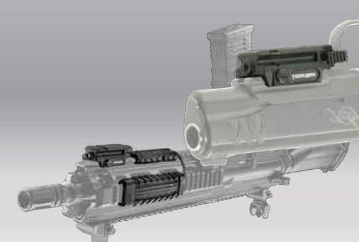
2 PARTS IDENTIFICATION Right Housing R L lens left activation switch right activation switch windage port elevation port Left Housing screw opening activation switch screw opening laser safety label mounting screws 1/3N battery adjustment tool
3 ! IMPORTANT: Prior to installation, battery change, cleaning or maintenance, follow the firearm operator s manual to ensure that the firearm is unloaded INSTALLATION To separate laser from its packaging, first rotate the disposable rail support upward to expose mounting screws. You may need to press the two small posts on rail support to release them from the tray (figure 1). 2. Use a Phillip s screwdriver (not provided) to remove the two (2) mounting screws from left housing (figure 2). Set these screws aside. 3. Separate the left housing from the right housing. 4. Place right housing onto Picatinny rail as shown (figure 3). 5. Mate left housing with right housing, ensuring that activation switch passes through opening in left housing (figure 4). 6. Press together to remove gap (figure 5). 7. Insert two (2) mounting screws into recessed screw holes in left housing. 4
4 5 6! Important: LMS-RMSR mounting screws are self-tapping; extra care should be taken when installing them for the first time to ensure that they are screwed in straight. Improper installation could cause the threads to strip. 8. Tighten mounting screws with a Phillips screwdriver (not provided). Do not over-tighten. OPERATION 1. To turn the laser on, press in on the activation switch from either side (figure 7). Press again to turn the laser off. 2. To switch aiming point from pulse to steady, press and release the activation switch from either side to activate the laser. Then, press and hold the activation switch for 5 seconds. The laser mode will change. Repeat the process to return to the previous mode. Note: When reactivated, laser will always return to the previously set mode. 3. To save power and prevent inadvertent battery drain, the LMS-RMSR will shut off automatically after a ten minute period of inactivity. Cycle the activation switch to turn laser back on. 7
5 ALIGNING THE LASER 1. Alignment adjustments should be made at a minimum of 10 yards distance from the target. To begin, insert adjustment tool into one of the two alignment ports (figures 8 & 9) and slowly rotate the tool while comparing laser position on target to fixed sights. The laser dot should be centered, slightly above top of front sight. Important: Do not rotate adjustment tool more than one full turn in either direction from the factory position doing so may cause damage to the laser and void the warranty. A one quarter turn will result in a movement of approximately 3 inches at 10 yards. 2. Windage adjustment: with the muzzle pointing forward and adjustment tool inserted into the windage port, a clockwise turn will shift the laser aiming point to the left and a counterclockwise turn will shift the laser beam to the right (figure 8). 3. Elevation adjustment: with the muzzle pointing forward and adjustment tool inserted into the elevation port, a clockwise turn will shift the laser beam up and a counterclockwise turn will shift the laser beam down (figure 9). 4. Verify zero by shooting targets and making additional adjustments as needed. Note: a slight shift in alignment may be observed after firing the first time. Recheck alignment after break in and readjust as necessary. 8 9
6 BATTERY REPLACEMENT TIP: During periods of non-use, test the LaserMax laser periodically to ensure adequate T battery levels. 1. Remove mounting screws to separate left housing from right housing. 2. Lift expended 1/3N Lithium battery out of right housing. 3. Install a fresh 1/3N Lithium battery with the negative (-) side toward circuit board and positive (+) side against the coiled spring (figure 3). 4. Mate left housing with right housing, ensuring that activation switch passes through opening in left housing (figure 5). Press together to remove gap. 5. Insert two (2) mounting screws into recessed screw holes in left housing. 6. Tighten mounting screws with a Phillips screwdriver (not provided). Do not over-tighten. CLEANING & MAINTENANCE After repeated fire, the lens may become clouded with gunpowder residue. For best results, it is recommended that this area be cleaned, along with the firearm, after each use. To clean the lens, follow these steps. 1. Keep firearm pointed in a safe direction. 2. Confirm laser is off. 3. Dampen the end of a cotton swab with isopropyl alcohol. 4. Apply dampened swab to lens and polish in a small circular pattern. Be sure to clean around edges of lens. LaserMax components should never be submerged or flushed with cleaning solvents. Failure to adhere to these guidelines may cause damage and void the factory warranty.
7 REPLACEMENT PARTS LMS-AT50 adjustment tool LMS-13N replacement battery LMS-2x13N 2-pack replacement batteries CF-MS mounting screws
8 IF YOU EXPERIENCE AN ISSUE WITH YOUR LASER PLEASE DO NOT RETURN IT TO THE STORE. LMS-RMSR Red Laser CLASS 3R VISIBLE LASER Output Power: <5mW Wavelength: nm REMINDER Aiming a laser beam at moving vehicles including boats, aircraft, trains, and construction equipment may be illegal. Check current applicable laws and follow them accordingly. DANGER Laser radiation is emitted from the front aperture of the laser when the switch is activated. WARNING Avoid direct eye exposure to beam. Do not point laser at anything you do not wish to destroy. NOTICE: The FDA requires the label supplied with your laser be affixed to the outside of the gun near the laser aperture.


9 Micro II RAIL MOUNTED LASERS
10 PARTS IDENTIFICATION elevation port lens battery hatch clamping screw 1/3N battery battery hatch tab windage port activation switch locking nut adjustment tool REPLACEMENT PARTS LMS-AT50 adjustment tool LMS-13N replacement battery LMS-2x13N 2-pack replacement batteries LMS-MICRO-CS clamping screw
11 IMPORTANT: PRIOR TO INSTALLATION, BATTERY CHANGE, CLEANING OR MAINTENANCE, FOLLOW THE FIREARM OPERATOR S MANUAL TO ENSURE THAT THE FIREARM IS UNLOADED. INSTALLATION 1. To remove laser from package use a flat head screwdriver (not supplied) to unscrew clamping screw from right side of laser housing. 2. Position Micro II on firearm rail. 3. Guide Micro II into position, aligning clamping screw hole with preferred notch on rail (see figure 1). 4. Insert clamping screw into right side of laser housing (see figure 2). When fully inserted, clamping screw will engage locking nut. 5. Tighten clamping screw with a flat head screwdriver (not supplied). Note: Variations in depth of handgun rail notches may require that clamping screw be pressed from locking nut end to remove. OPERATING INSTRUCTIONS 1. To turn the laser on, press and release the activation switch from either side (see figure 3). Press and release again to turn the laser off. 2. To switch the laser aiming point from pulse to steady, turn the laser on, then press and hold the activation switch for 3 seconds. Press and hold the activation switch for 3 seconds again to return to the previous mode. 3. To save power and prevent inadvertant battery drain, Micro II will shut off automatically after a ten minute period of inactivity. Cycle the activation switch to turn the laser back on
12 ALIGNING THE LASER 1. Alignment adjustments should be made at a minimum of 10 yards distance from the target. To begin, insert the adjustment tool into one of the two alignment ports (figures 4 & 5) and slowly rotate the tool while comparing the laser position on target to the fixed sights. Important: Do not turn alignment screws more than one full turn in either direction from their factory position. This may cause damage to the laser and void the warranty. A one quarter turn will result in a movement of about 7 inches at 10 yards. 2. Windage adjustment: with the muzzle pointing forward and adjustment tool inserted into the alignment port on the right side, a clockwise turn will shift the laser aiming point to the left and a counterclockwise turn will shift the laser beam to the right. 3. Elevation adjustment: with the muzzle pointing forward and adjustment tool inserted into the alignment port on the bottom, a clockwise turn will shift the laser beam down and a counterclockwise turn will shift the laser beam up. Note: a slight shift in alignment may be observed after firing Micro II for the first time. Recheck alignment after break in and readjust as necessary. BATTERY REPLACEMENT Micro II can remain on the firearm or be removed to change the battery. 1. Keep firearm pointed in a safe direction Press and hold battery hatch near tab (see figure 6). 6
13 While maintaining pressure on battery hatch with one hand, use the other hand to press battery hatch tab away from battery hatch (see figure 7). 3. Release battery hatch to expose battery chamber. 4. Replace expended battery with fresh 1/3N battery. The flat, inscribed side of battery should face outward (see figure 8). 5. Secure battery hatch by applying gentle pressure until it snaps closed. CLEANING After repeated fire, the lens may become clouded with gunpowder residue. For best results, it is recommended that this area be cleaned, along with the firearm, after each use. To clean the lens, follow these steps: Keep firearm pointed in a safe direction. 2. Confirm laser is off. 3. Dampen the end of a cotton swab with isopropyl alcohol. 4. Apply dampened swab to lens and polish in a small circular pattern. Be sure to clean around edges of lens. WARNING Care should be taken when applying oil or lubricant to clean the firearm. Getting oil or lubricant on the laser components may cause damage and void the factory warranty. The Micro II should not be submerged or flushed with cleaning solvents.
14 IF YOU EXPERIENCE AN ISSUE WITH YOUR MICRO II LASER, PLEASE DO NOT RETURN IT TO THE STORE. MICRO-2-R Red Laser CLASS 3R VISIBLE LASER Output Power: <5mW Wavelength: 650nm MICRO-2-G Green Laser CLASS 3R VISIBLE LASER Output Power: <5mW Wavelength: nm MICRO-2-IR Infrared Laser CLASS 1 LASER Output Power: <0.7mW Wavelength: 850nm ITAR CONTROLLED CLASS 1 LASER PRODUCT <0.7mW Wavelength: 850nm COMPLIES WITH 21CFR1040 PER LASER NOTICE 50 (2007) REMINDER Aiming a laser beam at moving vehicles including boats, aircraft, trains, and construction equipment may be illegal. Check current applicable laws and follow them accordingly. DANGER Laser radiation is emitted from the front aperture of the laser when the switch is activated. WARNING Avoid direct eye exposure to beam. Do not point laser at anything you do not wish to destroy.


15 ADJUSTABLE FIT LASER Operator s Manual Advanced mounting technology provides the perfect fit Accessory rail permits attachment of tactical light Aiming point can be set to operator s choice of pulse or steady Auto-off after 10 minutes preserves battery power
16 PARTS IDENTIFICATION Right Housing SPARTAN lens paddle switch windage port elevation port Left Housing screw openings rail vise positioner laser safety label clamping screws 1/3N battery adjustment tool
17 IMPORTANT: PRIOR TO INSTALLATION, BATTERY CHANGE, CLEANING OR MAINTENANCE, FOLLOW THE FIREARM MANUFACTURER S INSTRUCTIONS TO ENSURE THAT THE FIREARM IS UNLOADED. INSTALLATION 1. To separate Spartan from its packaging, first rotate the disposable rail support upward to expose clamping screws. You may need to press the two small posts on rail support to release them from the tray (figure 1). 2. Use a Phillip s head screwdriver (not provided) to remove the two (2) clamping screws from left housing (figure 2). Set these screws aside Separate the left and right laser housings. Remove rail vise positioner (figure 3) and set it aside Identify the right housing and take note of its slotted channels (figure 4). 5. Position the right housing against the rail of the firearm as shown (figure 5). Hold in place on rail at the desired location between trigger guard and muzzle. SPARTAN 1 2
18 6. Slide the curved front end of rail vise positioner into the Picatinny rail slot and position the three teeth into the corresponding slotted channels in right housing (figure 6). Note: While holding this assembly in place with your support hand, assume a normal grip on the firearm and 6 test the trigger finger s reach to the paddle switch to ensure optimal placement on the rail. To customize the fit, remove right housing, reposition as desired, then place the slotted channels of right housing back onto the teeth of rail vise positioner in its new, preferred location. 7. Mate left laser housing with right housing and press the two halves together to close the gap. 8. While holding the completed assembly in place on the pistol rail, insert two (2) clamping screws into the holes in the left housing (figure 7). 9. Partially tighten clamping screws with a Phillip s head screwdriver (not provided). Ensure that the laser is attached at the desired point on the rail before completely tightening the screws. Do not overtighten. OPERATING INSTRUCTIONS 1. To turn the laser on, press and release the paddle switch from either side. Press and release again to turn the laser off. 2. To switch the laser aiming point from pulse to steady, turn the laser on, then press and hold the paddle switch for 5 seconds. Press and hold the paddle switch again to return to the previous mode. 3. To save power and prevent inadvertent battery drain, Spartan will turn off automatically after a ten minute period of inactivity. Cycle the paddle switch to turn the laser back on. 7
19 ALIGNING THE LASER SPARTAN 1. Alignment adjustments should be made at a minimum of 10 yards distance from the target. To begin, insert the adjustment tool into one of the two alignment ports (figures 8 & 9) and slowly rotate the tool while comparing the laser position on target to the fixed sights. Important: Do not turn alignment screws more than one full turn in either direction from their factory position. This may cause damage to the laser and void the warranty. A one quarter turn will result in a movement of about 7 inches at 10 yards. 2. Windage adjustment: with the muzzle pointing forward and the adjustment tool inserted into the alignment port on the right side, a clockwise turn will shift the laser aiming point to the right and a counterclockwise turn will shift the laser beam to the left. 3. Elevation adjustment: with the muzzle pointing forward and the adjustment tool inserted into the alignment port on the bottom, a clockwise turn will shift the laser beam down and a counterclockwise turn will shift the laser beam up. Note: a slight shift in alignment may be observed after firing Spartan for the first time. Recheck alignment after break in and readjust as necessary. BATTERY REPLACEMENT 8 9 Spartan can remain on the firearm or be removed to change batteries. Follow these steps: 1. Use a Phillips head screwdriver to remove clamping screws from left housing. 2. Remove left housing to expose the battery compartment.
20 10 3. Carefully remove the expended 1/3N battery (see figure 10). 4. Insert a fresh 1/3N battery with the negative ( ) side facing the gold contact. 7. Partially tighten the screws with a Phillips screwdriver. 5. Mate left housing with right housing and press the two halves together to close the gap. 6. While holding the assembly in place on the pistol rail, insert two (2) clamping screws into the holes in left housing. 8. Ensure that the laser is attached at desired point on rail before completely tightening the screws. Do not over-tighten. CLEANING After repeated fire, the lens may become clouded with gunpowder residue. For best results, it is recommended that this area be cleaned along with the firearm after each use. To clean the lens, follow these steps: 1. Keep firearm pointed in a safe direction. 2. Confirm laser is off. 3. Dampen the end of a cotton swab with isopropyl alcohol. 4. Apply dampened swab to lens and polish in a small circular pattern. Be sure to clean around the edges of the lens. WARNING Care should be taken when applying oil or lubricant to clean the firearm. Getting oil or lubricant on laser components may cause damage and void the factory warranty. Spartan should not be submerged in or flushed with lubricants or cleaning solvents.
21 REPLACEMENT PARTS rail vise positioner LMS-AT50 adjustment tool LMS-13N replacement battery LMS-2x13N 2-pack replacement batteries CF-MS clamping screws
22 IF YOU EXPERIENCE AN ISSUE WITH YOUR SPARTAN LASER PLEASE DO NOT RETURN IT TO THE STORE. SPS-R Red Laser CLASS 3R VISIBLE LASER Output Power: <5mW Wavelength: 650nm SPS-G Green Laser CLASS 3R VISIBLE LASER Output Power: <5mW Wavelength: nm REMINDER Aiming a laser beam at moving vehicles including boats, aircraft, trains, and construction equipment may be illegal. Check current applicable laws and follow them accordingly. DANGER Laser radiation is emitted from the front aperture of the laser when the switch is activated. WARNING Avoid direct eye exposure to beam. Do not point laser at anything you do not wish to destroy. NOTICE: The FDA requires the label supplied with your laser be affixed to the outside of the gun near the laser aperture.


23 Uni RAIL MOUNTED LASERS LMS-UNI-ES LMS-UNI-G LMS-UNI-IR LMS-UNI-ES-RVP LMS-UNI-GVP LMS-UN-IR-RVP

24 LMS-UNI-ES LMS-UNI-G LMS-UNI-IR
25 PARTS IDENTIFICATION removable rail grip lens integrated rail clamping screw activation switch LMS-UNI-ES LMS-UNI-IR battery cover 357 batteries battery cover screws LMS-UNI-G adjustment tool battery cover 1/3N batteries
26 ! IMPORTANT: Prior to installation, battery change, cleaning or maintenance, follow the firearm operator s manual to ensure that the firearm is unloaded. INSTALLATION ON PISTOL RAIL 1. To separate UNI from its packaging, first rotate the disposable rail support upward to expose clamping screw. You may need to press the two small posts on rail support to release them from the tray (figure 1). 2. Loosen clamping screw with a coin or flat head screwdriver (not provided). Do not remove clamping screw. 3. While gripping UNI housing, press in on clamping screw to expand opening of removable rail grip (figure 2) and remove from disposable rail support packaging. 4. Mount UNI on firearm rail as shown (figure 3), then release pressure on clamping screw. Ensure that UNI is securely positioned on rail surface and clamping screw is seated into rail notch. 5. Tighten clamping screw with a coin or flat head screwdriver. 6. Additional accessories may now be mounted to UNI s integrated rail following the accessory manufacturer s instructions
27 OPERATION 1. To turn laser on, press in on activation switch from either side (figure 4). Return switch to center position to turn laser off. 2. To switch laser aiming point from pulse to steady, turn laser on for at least two seconds, then turn it off. Next, cycle laser on and off three times from the same side, stopping at the center position between each cycle (each on/off cycle should take less than half of a second). To return the laser to the previous mode, repeat the process. 3. To save power and prevent inadvertent battery drain, UNI will shut off automatically after a ten minute period of inactivity. Cycle the activation switch to turn laser back on. ALIGNING THE LASER 1. Alignment adjustments should be made at a minimum of 10 yards distance from the target. To begin, insert adjustment tool into one of the two alignment ports (figures 5 & 6) and slowly rotate the tool while comparing laser position on target to fixed sights. Important: Do not turn alignment screws more than one full turn in either direction from the factory position. This may cause damage to the laser and void the warranty. A one quarter turn will result in a movement of about 3 inches at 10 yards. 2. Windage adjustment: with the muzzle pointing forward and adjustment tool inserted into windage port, a clockwise turn will shift the laser aiming point to the left and a counterclockwise turn will shift it to the right (figure 5). 3. Elevation adjustment: with the muzzle pointing forward and adjustment tool inserted into elevation port, a clockwise turn will shift the laser aiming point down and a 4
28 5 6 counterclockwise turn will shift it up (figure 6). Note: a slight shift in alignment may be observed after firing the first time. Recheck alignment after break-in and readjust as necessary. BATTERY REPLACEMENT 7 battery cover slot 8 1. Loosen both battery cover screws with a Philips head screwdriver to remove battery cover. 2. Turn UNI over to eject expended batteries. 3. Insert fresh batteries as shown (figure 7). 4. Reinsert battery cover by sliding edge of battery cover into battery cover slot (figure 8). 5. Reinstall battery cover screws to secure battery cover. Do not overtighten.
29 CLEANING After repeated fire, the lens may become clouded with gunpowder residue. For best results, it is recommended that this area be cleaned, along with the firearm, after each use. To clean the lens, follow these steps: 1. Keep firearm pointed in a safe direction. 2. Confirm laser is off. 3. Dampen the end of a cotton swab with isopropyl alcohol. 4. Apply dampened swab to lens and polish in a small circular pattern. Be sure to clean around edges of lens. REPLACEMENT PARTS battery cover (UNI-ES & UNI-IR) LMS-UNI-BCN-G battery cover (UNI-G) LMS-UBCS battery cover screws LMS 2X357 (2) 357 batteries (UNI-ES & UNI-IR) LMS 2X13N (2) 1/3N batteries (UNI-G) LMS-AT50 adjustment tool LMS UNI CS clamping screw with spring LMS UNI RG removable rail grip LMS UNI AS activation switch activation switch cover LMS-SCS activation switch cover screws LMS-UNI-MAS- 6 momentary switch 6 cord LMS-UNI-MAS-10 momentary switch 10 cord LMS-MANTA manta rail cover system

30 LMS-UNI-ES-RVP LMS-UNI-GVP LMS-UNI-IR-RVP
31 RIFLE PACK PARTS IDENTIFICATION removable rail grip LMS-UNI-ES LMS-UNI-IR lens integrated rail clamping screw activation switch LMS-UNI-G battery cover 357 batteries adjustment tool battery cover screws battery cover 1/3N batteries lubricant cord cover end cap connector pressure pad sleeve momentary activation switch (MAS) activation switch cover cord end cap activation switch cover screws
32 INSTALLATION OF MOMENTARY ACTIVATION SWITCH (MAS) All UNI lasers leave the factory configured for use with the standard activation switch. To change to the rifle (MAS) configuration, follow these steps: 1. Loosen battery cover screws with a Philips head screwdriver (not provided). Do not remove. 2. Remove activation switch cover screws (figure 9) and set aside. 3. Carefully remove activation switch cover and activation switch. Store these parts for future use (figure 10). 4. Insert connector of momentary activation switch into opening in UNI as shown (figure 11). 5. Reinstall activation switch cover screws to secure connector. Do not overtighten. 6. Tighten battery cover screws. Do not overtighten. 7. Shift the UNI master ON/OFF switch toward the cable to activate the pressure pad of the momentary activation switch (figure 12). Verify connection by pressing the pressure pad. The UNI laser aiming point will now illuminate whenever the pressure pad is pressed. T Tip: Slide Uni master ON/OFF switch to the OFF position during transport or when not is use to prevent inadvertant activation
33 INSTALLATION ON RIFLE RAIL To install on rifle rail, first, loosen clamping screw with a coin or flat head screwdriver (not provided). Do not remove clamping screw. 2. While gripping UNI housing, press in on clamping screw to enlarge removable rail grip opening (figure 13). 3. Mount UNI on firearm rail as shown (figure 14), then release pressure on clamping screw. Ensure that UNI is securely positioned on rail surface and clamping screw is seated into rail notch. 4. Tighten clamping screw with a coin or flat head screwdriver. 5. Additional accessories may now be mounted to UNI s integrated rail following the accessory manufacturer s instructions. INSTALLATION OF MANTA CORD MANAGEMENT SYSTEM 1. Insert pressure pad through front of Manta end cap (figure 15 ). 15
34 Coat pressure pad with a small amount of lubricant to aid in installation. 3. Slide lubricated pressure pad into Manta sleeve as shown (figure 16) 4. Position assembled momentary activation switch at desired location on firearm, angling to hook edge of Manta sleeve on firearm rail (figure 17). 5. Snap opposing edge of Manta sleeve onto firearm rail to secure. 6. Attach remaining Manta end cap on opposite side of Manta sleeve (figure 18) Adjust Manta end caps to achieve desired placement. 8. Snap supplied Manta cord cover over cord to ensure snag-free operation (figure 19).
35 IF YOU EXPERIENCE AN ISSUE WITH YOUR UNI LASER, PLEASE DO NOT RETURN IT TO THE STORE. LMS-UNI-ES LMS-UNI-ES-RVP Red Laser CLASS 3R VISIBLE LASER Output Power: <5mW Wavelength: nm LMS-UNI-G LMS-UNI-GVP Green Laser CLASS 3R VISIBLE LASER Output Power: <5mW Wavelength: nm LMS-UNI-IR LMS-UNI-IR-RVP Infrared Laser CLASS 1 LASER Output Power: <0.7mW Wavelength: nm ITAR CONTROLLED CLASS 1 LASER PRODUCT <0.7mW Wavelength: nm COMPLIES WITH 21CFR1040 PER LASER NOTICE 50 (2007) REMINDER Aiming a laser beam at moving vehicles including boats, aircraft, trains, and construction equipment may be illegal. Check current applicable laws and follow them accordingly. DANGER Laser radiation is emitted from the front aperture of the laser when the switch is activated. WARNING Avoid direct eye exposure to beam. Do not point laser at anything you do not wish to destroy.
FastFire 2. Red Dot Reflex Sight
 FastFire 2 Red Dot Reflex Sight Congratulations on purchasing the Burris FastFire 2! This versatile red dot reflex sight will be the perfect fast-action sighting solution for your handgun, rifle or shotgun.
X SERIES GEN 3 MANUAL
 X SERIES GEN 3 MANUAL CONGRATULATIONS on your purchase of a Viridian X SERIES Gen 3, the most advanced sighting device available. IF YOU HAVE TECHNICAL OR SERVICE ISSUES WITH THIS PRODUCT, DO NOT RETURN
USER MANUAL. Mini Shot Pro Spec. SM26003 and SM English / Francais / Español
 USER MANUAL Mini Shot Pro Spec SM26003 and SM26004 English / Francais / Español ABOUT SIGHTMARK Sightmark offers a wide range of products that include red dot scopes, reflex sights, rangefinders, riflescopes,
Heavy Duty Flashlight Foregrip USER MANUAL. English
 Heavy Duty Flashlight Foregrip USER MANUAL English VICTORY JUSTIFIES EVERYTHING The Firefield brand has recently launched with products designed to maximize every intense moment. Originally designed for
FastFire 3 Red Dot Reflex Sight
 FastFire 3 User Guide_Layout 1 10/2/15 8:55 AM Page 1 FastFire 3 User Guide_Layout 1 10/2/15 8:55 AM Page 2 FastFire 3 Red Dot Reflex Sight Congratulations on purchasing the Burris FastFire 3! This versatile
TABLE OF CONTENTS GENERAL INFO C SERIES X SERIES
 OWNER S MANUAL TABLE OF CONTENTS GENERAL INFO 3 SAFETY 4 WARNINGS 6 MAINTENANCE 7 ZEROING 9 ECR INSTANT-ON TECHNOLOGY 10 WARRANTY INFO 11 SERVICE INFO C SERIES 13 C SERIES DIAGRAM 14 GENERAL INFO 15 BATTERY
Please read entire manual before using your new optic. Ocular Lens. Flip Caps. Objective Lens. Windage Adjustment
 The Vortex SPARC II Red Dot Sight The rugged, streamlined SPARC II with daylight-bright red dot lends itself to a variety of firearm platforms including AR-15s, shotguns and pistols. The multi-height base
Power Supply, 17-inch
 apple imac G5 Power Supply, 17-inch Replacement Instructions Follow the instructions in this sheet carefully. Failure to follow these instructions could damage your equipment and void its warranty. Note:
Adjustments 1 click = 10 mm at 100 m =.36 in at 100 yds Adjustment range (windage and elevation) Dot size 2 MOA 1 Dot intensity settings
 Dot size 2 MOA 1 Dot intensity settings") CompM5 User manual 1 PRESENTATION Aimpoint red dot sights are designed for the two eyes open method which greatly enhances situational awareness and target acquisition. Thanks to the optical design the
CompM5 User manual 1 PRESENTATION Aimpoint red dot sights are designed for the two eyes open method which greatly enhances situational awareness and target acquisition. Thanks to the optical design the
MARK III TACTICAL SERIES
 MARK III TACTICAL SERIES The Mark III Tactical Series offers a compact optical system packed with many features making it very user friendly. Two mounting system options make for easy mounting with a Quick
Replacement Instructions
 imac G5 Inverter, 20-inch Replacement Instructions Follow the instructions in this document carefully. Failure to follow these instructions could damage your equipment and void its warranty. Note: Online
Shockproof Housing. Scratchproof Sight Window. Scratchproof Sight Window. Windage Adjustment. On/Off Buttons. Elevation Adjustment.
 Shockproof Housing Scratchproof Sight Window The incredible features of the Razor AMG UH-1 are matched only by its tough, tenacious performance. Absolute zero image distortion and an impressive sight picture
USER MANUAL TACTICAL MAGNIFIER WITH SLIDE TO SIDE MOUNT. 3x, 5x, and 7x. English SM19037, SM19038, SM19039
 USER MANUAL TACTICAL MAGNIFIER WITH SLIDE TO SIDE MOUNT 3x, 5x, and 7x SM19037, SM19038, SM19039 English ABOUT SIGHTMARK Sightmark offers a wide range of products that include red dot scopes, reflex sights,
G12/G12x USER S MANUAL
 G12/G12x USER S MANUAL TABLE OF CONTENTS SECTION 1 SLIDE CONFIGURATION SECTION 2 SLIDE CONFIGURATION ACCESSORIES SECTION 3 TABLETOP CONFIGURATION SECTION 4 TABLETOP CONFIGURATION ACCESSORIES SECTION 5
Replacing the Power Supply
 APPENDIX B This appendix includes information on how to replace the power supply for the Cisco AS550XM universal gateway and contains the following sections: Safety Recommendations, page B-1 Required Tools
QUAD 1000 OWNERS MANUAL OPERATION GUIDE
 QUAD 1000 OWNERS MANUAL OPERATION GUIDE Built in Redmond Oregon USA COMPONENTS 4001-0000 Quad 1000 5 arc second zenith laser featuring electronic servo self-leveling with variable temperature compensation
So go out and enjoy your new rangefinder (after reading the manual, of course), and thank you for choosing SWR.
, and thank you for choosing SWR.") TM Thank you for choosing to add a SilencerCo Weapons Research item to your collection. We love what we do and take great pride in the products we produce, and hope you will enjoy using this product as
TM Thank you for choosing to add a SilencerCo Weapons Research item to your collection. We love what we do and take great pride in the products we produce, and hope you will enjoy using this product as
TABLE OF CONTENTS SECTION 1 TABLETOP CONFIGURATION SECTION 2 TABLETOP CONFIGURATION ACCESSORIES SECTION 3 SLIDE CONFIGURATION
 S6 USER S MANUAL TABLE OF CONTENTS SECTION 1 TABLETOP CONFIGURATION SECTION 2 TABLETOP CONFIGURATION ACCESSORIES SECTION 3 SLIDE CONFIGURATION SECTION 4 SLIDE CONFIGURATION ACCESSORIES SECTION 5 RACK MOUNT
ERGONOMIC MODULAR RAIL V3 M-LOK. ALG Defense 800 East Walnut Street North Wales, PA algdefense.com
 TM ERGONOMIC MODULAR RAIL V3 M-LOK ALG Defense 800 East Walnut Street North Wales, PA19454 610.635.8937 algdefense.com TM ERGONOMIC MODULAR RAIL V3 M-LOK PACKAGE CONTENTS Ergonomic Modular Rail V3 with
Encore XT Manual Gun Upgrade Kit
 Instruction Sheet P/N 1600823-01 Encore XT Manual Gun Upgrade Kit 1600834 Introduction Follow these instructions to upgrade your Encore manual spray gun to the improved design of the Encore XT spray gun.
Survival Laser SL-001.4PB Laser Parts Bundle Assembly & Operation Instructions
 Survival Laser SL-001.4PB Laser Parts Bundle Assembly & Operation Instructions WARNING: READ ALL INSTRUCTIONS AND THE ENCLOSED SAFETY PRECAUTIONS BEFORE ASSEMBLY AND USE Assemble and use these parts ONLY
Survival Laser SL-VPB Laser Parts Bundle Assembly & Operation Instructions
 Survival Laser SL-VPB Laser Parts Bundle Assembly & Operation Instructions WARNING: READ ALL INSTRUCTIONS AND THE ENCLOSED SAFETY PRECAUTIONS BEFORE ASSEMBLY AND USE Assemble and use these parts ONLY in
Zebra XiII-Series Printer Quick Reference Guide
 Zebra XiII-Series Printer Quick Reference Guide Contents Media and Ribbon Loading...67 Media Loading...67 Ribbon Loading...70 Operator Controls...72 Front Panel Keys...72 Front Panel Lights...72 Calibration...74
Photon Riflescope 3.5x42 / 5x42 / Photon-S 3.5x42 / Photon-S 5x42
 USER MANUAL Photon Riflescope 3.5x42 / 5x42 / Photon-S 3.5x42 / Photon-S 5x42 SM18004 / SM18003 / SM18006 / SM18005 English ABOUT SIGHTMARK Sightmark offers a wide range of products that include red dot
Hard Drive, 20-inch. Replacement Instructions
 apple imac G5 Hard Drive, 20-inch Replacement Instructions Follow the instructions in this document carefully. Failure to follow these instructions could damage your equipment and void its warranty. Note:
ATN IR850 Pro. LONG RANGE 850 mw INFRA-RED ILLUMINATOR. USER S GUIDE (IR850 PRO) REVISION 2 AUGUST, 2017 user s guide
 REVISION 2 AUGUST, 2017 user s guide") ATN IR850 Pro LONG RANGE 850 mw INFRA-RED ILLUMINATOR USER S GUIDE (IR850 PRO) REVISION 2 AUGUST, 2017 user s guide Important Export Restrictions! Commodities, products, technologies and services contained
ATN IR850 Pro LONG RANGE 850 mw INFRA-RED ILLUMINATOR USER S GUIDE (IR850 PRO) REVISION 2 AUGUST, 2017 user s guide Important Export Restrictions! Commodities, products, technologies and services contained
Aimpoint PRO User manual
 Aimpoint PRO User manual 1 PRESENTATION Aimpoint sights are designed for the both eyes open method of sighting which greatly enhances situational awareness and target acquisition speed. Thanks to the parallax-free
Survival Laser SL-005PB Laser Parts Bundle Assembly & Operation Instructions
 Survival Laser SL-005PB Laser Parts Bundle Assembly & Operation Instructions WARNING: READ ALL INSTRUCTIONS AND THE ENCLOSED SAFETY PRECAUTIONS BEFORE ASSEMBLY AND USE Assemble and use these parts ONLY
ipod Classic Click Wheel Replacement Written By: irobot ifixit CC BY-NC-SA Page 1 of 25
 ipod Classic Click Wheel Replacement Written By: irobot ifixit CC BY-NC-SA www.ifixit.com Page 1 of 25 INTRODUCTION The click wheel receives the feedback of your fingers and transmits it to the logic board.
INSTALLATION INSTRUCTIONS
 TT-40 9/0 INSTALLATION INSTRUCTIONS Original Issue Date: 9/0 Model: Automatic Transfer Switches Equipped with the Programmable Controller Market: ATS Subject: External Battery Supply Module Kit GM69-KP
ipod Classic Headphone Jack & Hold Switch Replacement
 ipod Classic Headphone Jack & Hold Switch Replacement Replace Headphone Jack & Hold Switch to fix no audio and/or no unlock Written By: irobot ifixit CC BY-NC-SA www.ifixit.com Page 1 of 22 INTRODUCTION
Gateway Profile 4 service guide
 Gateway Profile 4 service guide Customizing Troubleshooting Contents Replacing Components in Your Gateway Profile 4.................. 1 About this guide.....................................................
MD-BSL15W / SPRING-LOADED TWIN-ARM. For ( cm) LCD desktop computer. User Manual
 LCD desktop computer. User Manual") MD-BSL15W / SPRING-LOADED TWIN-ARM MONITOR mount For 15 27 (38.1 68.6 cm) LCD desktop computer User Manual Thank you for choosing Gabor. The Gabor MD-BSL15W mounts two 15 27 (38.1 68.6 cm) LCD computer
MD-BSL15W / SPRING-LOADED TWIN-ARM MONITOR mount For 15 27 (38.1 68.6 cm) LCD desktop computer User Manual Thank you for choosing Gabor. The Gabor MD-BSL15W mounts two 15 27 (38.1 68.6 cm) LCD computer
DUAL-ARM MONITOR MOUNT For in. ( cm) desktop computer monitors
 desktop computer monitors") LeviTouch DM-502 DUAL-ARM MONITOR MOUNT For 15 27 in. (38.1 68.6 cm) desktop computer monitors User Manual Thank you for choosing Gabor. The Gabor Dual-Arm Desktop Mount can securely support two monitors
LeviTouch DM-502 DUAL-ARM MONITOR MOUNT For 15 27 in. (38.1 68.6 cm) desktop computer monitors User Manual Thank you for choosing Gabor. The Gabor Dual-Arm Desktop Mount can securely support two monitors
C-pan arm USERS INSTRUCTIONS
 C-pan arm USERS INSTRUCTIONS Designed 1 of 12 and made in Denmark Thanks for purchasing a 9.Solutions product. With great passion, we design our products to be as versatile as possible. We hope that our
PVS-14 Slide to Side Quick Detach Weapon Mount
 USER MANUAL PVS-14 Slide to Side Quick Detach Weapon Mount SM34001 English ENGLISH FEATURES: Slide to side action Quick detach weaver mount Made from durable aluminum Fits PVS-14 monocular TECHNICAL SPECIFICATIONS:
To connect the AC adapter:
 Replacing the AC Adapter Replacing the AC Adapter 3 Plug the power cord into a wall outlet. The power indicator turns on. To connect the AC adapter: Connect the power cord to the AC adapter. Power indicator
Operating Manual. AdirPro HV8RL Red Beam Horizontal/Vertical Laser level
 Operating Manual AdirPro HV8RL Red Beam Horizontal/Vertical Laser level Maintenance and Safety The HV8RL is a class II laser according to 21CFR1040. Be careful not to expose your eyes to the laser beam.
Survival Laser SL-002PB Laser Parts Bundle w/g-1 Lens Assembly & Operation Instructions
 Survival Laser SL-002PB Laser Parts Bundle w/g-1 Lens Assembly & Operation Instructions WARNING: READ ALL INSTRUCTIONS AND THE ENCLOSED SAFETY PRECAUTIONS BEFORE ASSEMBLY AND USE Assemble and use these
JLTX Lever and Joystick Replacement Instructions
 JLTX Lever and Joystick Replacement Instructions WARNING THE INCORRECT INSTALLATION OF A LEVER OR JOYSTICK CAN CAUSE AN EQUIPMENT MALFUNCTION FAILURE TO FOLLOW THIS PROCEDURE CAREFULLY COULD RESULT IN
Underwater Housing for Panasonic Lumix DMC-LX10, LX15
 Underwater Housing for Panasonic Lumix DMC-LX10, LX15 Product Number 6171.01 Product Registration Please register your product at ikelite.com within 15 days of purchase. Our product registration database
Written By: Ben Eisenman
 iphone 3GS Rear Panel Replacement Replace a broken rear case on your iphone 3GS. Written By: Ben Eisenman ifixit CC BY-NC-SA www.ifixit.com Page 1 of 22 INTRODUCTION The plastic rear half of the iphone.
MEPRO 21 TRITIUM SELF-ILLUMINATED REFLEX SIGHT
 MEPRO 21 TRITIUM SELF-ILLUMINATED REFLEX SIGHT USER MANUAL Copyright Copyright 2011 by MEPROLIGHT. This document contains information which is the sole proprietary to Meprolight (1990) Ltd. ("MEPROLIGHT").
Dell Latitude V710/V740 Service Manual
 Dell Latitude V710/V740 Service Manual Dell Latitude V710/V740 Service Manual Before You Begin Preparing to Work Inside the Computer Recommended Tools Computer Orientation Screw Identification System Components
User s Manual for Aimpoint Comp and 7000 series CHAPTER I
 User s Manual for Aimpoint Comp and 7000 series CHAPTER I 1.1 Presentation Aimpoint s Reflex Sights are rugged precision electronic optical red dot sights developed for civilian, military and law enforcement
Samsung Galaxy S7 Edge Display Assembly
 Samsung Galaxy S7 Edge Display Assembly Replacement Removing and replacing the display assembly on the Samsung Galaxy S7 Edge. Written By: Arthur Shi ifixit CC BY-NC-SA www.ifixit.com Page 1 of 25 INTRODUCTION
Operator, Technical and Maintenance Manual for CompM XD and CompML XD
 Operator, Technical and Maintenance Manual for CompM XD and CompML XD Aimpoint AB Jägershillgatan 15 SE-213 75 Malmö, Sweden Tel. +46 40 671 50 20 Fax +46 40 21 92 38 e-mail info@aimpoint.se www.aimpoint.com
Xero A1/A1i. Owner s Manual
 Xero A1/A1i Owner s Manual 2018 Garmin Ltd. or its subsidiaries All rights reserved. Under the copyright laws, this manual may not be copied, in whole or in part, without the written consent of Garmin.
ASSET LGA1366 Top-side Probe
 ASSET LGA1366 Top-side Probe (Manual version 1.1) For gaining test access to the debug port of Intel processors that are designed for use in LGA1366 Sockets (Socket B). These include the Intel Core i7
OnePlus 5 Screen and Digitizer Assembly Replacement
 OnePlus 5 Screen and Digitizer Assembly Replacement Follow this guide to replace the screen and digitizer for the OnePlus 5. This replaces the screen as well as the frame it is attached to. Written By:
Written By: Sam Lionheart
 iphone 5s Earpiece Speaker Replacement Replace the earpiece speaker in an iphone 5s. Written By: Sam Lionheart ifixit CC BY-NC-SA www.ifixit.com Page 1 of 22 INTRODUCTION Use this guide to replace a broken
iphone 3G Headphone Jack Replacement Replace a broken audio port in an iphone 3G. Written By: irobot ifixit CC BY-NC-SA
 iphone 3G Headphone Jack Replacement Replace a broken audio port in an iphone 3G. Written By: irobot ifixit CC BY-NC-SA www.ifixit.com Page 1 of 18 INTRODUCTION No audio? Replace the headphone jack! TOOLS:
Dell Inspiron XPS and Inspiron 9100 Service Manual
 Dell Inspiron XPS and Inspiron 9100 Service Manual Dell Inspiron XPS and Inspiron 9100 Service Manual Before You Begin Memory Module, Mini PCI Card, and Devices System Components Subwoofer Bluetooth Card
Mk II 3DR MULTI-LINE LASER INSTRUCTION MANUAL
 Mk II 3DR MULTI-LINE LASER INSTRUCTION MANUAL SAFETY Read the following safety instructions before attempting to operate this product. Keep these instructions in a safe place or store in the carry case
Removal and Installation 8
 Removal and Installation 8 8 Introduction 8-2 Service Calibration Guide to Removal and Installation 8-4 Window 8-8 Covers and Trims 8-12 Rear Tray 8-31 Rear Cover 8-32 Media Lever 8-33 Media Lever Position
How to add a Second Drive to a Mac mini (2012) using the OWC Data Doubler SSD/2.5 Installation Kit
 using the OWC Data Doubler SSD/2.5 Installation Kit") Instructional Video Series How to add a Second Drive to a Mac mini (2012) using the OWC Data Doubler SSD/2.5 Installation Kit Skill Level: Challenging Time to Complete: Approximately 45 Minutes Required
Instructional Video Series How to add a Second Drive to a Mac mini (2012) using the OWC Data Doubler SSD/2.5 Installation Kit Skill Level: Challenging Time to Complete: Approximately 45 Minutes Required
HP Pavilion dv7-6c90us Cooling fan Replacement
 HP Pavilion dv7-6c90us Cooling fan Replacement This guide will walk you through the process of replacing the cooling fan in an HP Pavilion dv7 laptop. Written By: Angelina Clayton ifixit CC BY-NC-SA www.ifixit.com
DIGITAL OBSERVATION GUARD LOW PROFILE PAN TILT KIT USER MANUAL
 DIGITAL OBSERVATION GUARD LOW PROFILE PAN TILT KIT USER MANUAL Version 2.1 June 4, 2013 0 Table of Contents Low Profile Pan Tilt Kit Description... 3 Low Profile Pan Tilt Unit Basic Operation... 4 Mounting
Upgrading and Servicing Guide
 Upgrading and Servicing Guide The only warranties for Hewlett-Packard products and services are set forth in the express statements accompanying such products and services. Nothing herein should be construed
Upgrading and Servicing Guide
 Upgrading and Servicing Guide The only warranties for Hewlett-Packard products and services are set forth in the express statements accompanying such products and services. Nothing herein should be construed
Richter Optica. Instructions for: S6-BL, S6-TS, S6-SPS, S6-ILST Models
 Richter Optica info@richter-optica.com Instructions for: S6-BL, S6-TS, S6-SPS, S6-ILST Models Trinocular port for c-mount adapter Zoom Knob Focusing Holder Clamp Diopter adjustable eyepieces Magnification
CARTRIDGE REMANUFACTURING INSTRUCTIONS XEROX PHASER 6180 TONER CARTRIDGE
 XEROX PHASER 6180 CARTRIDGE REMANUFACTURING INSTRUCTIONS XEROX PHASER 6180 TONER CARTRIDGE REMANUFACTURING THE XEROX PHASER 6180 TONER CARTRIDGES By Mike Josiah and the Technical Staff at UniNet First
Removing and Replacing Parts
 Removing and Replacing Parts Preparing to Work Inside the Computer Recommended Tools Screw Identification System Components Hard Drive Fixed Optical Drive Media Bay Devices Memory Modules Mini PCI Card
Assembly and Usage Instructions. Product # Instruction # Revision A
 Assembly and Usage Instructions Product #488029 Instruction #1046698 Revision A Read these instructions in their entirety before using this product. Failure to follow this warning could result in property
Aimpoint CompM3 and Aimpoint CompML3
 User s Manual for Aimpoint CompM3 and Aimpoint CompML3 Aimpoint AB Jägershillgatan 15 SE- 213 75 Malmö, Sweden Phone +46 (0)40 671 50 20 Fax +46 (0)40 21 92 38 e-mail: info@aimpoint.se www.aimpoint.com
200DLM/A Underwater TTL Housing for Olympus OM-D E-M10 Mark III Mirrorless Micro Four-Thirds
 200DLM/A Underwater TTL Housing for Olympus OM-D E-M10 Mark III Mirrorless Micro Four-Thirds Product Number 6950.13 Product Registration Please register your product at ikelite.com within 15 days of purchase.
DCS200/DCS200-09/DCS DCS300/DCS300-09/DCS355
 THE SEEKER 200 SERIES & THE SEEKER 300 SERIES VIDEO INSPECTION SYSTEMS DCS200 (shown) DCS300 (shown) DCS200/DCS200-09/DCS200-05 DCS300/DCS300-09/DCS355 USER S MANUAL Please read this manual carefully and
BRAVO BRAVO4 4x30mm MEGAVIEW BATTLE SIGHT
 ELECTRO-OPTICS BRAVO BRAVO4 4x30mm MEGAVIEW BATTLE SIGHT OWNERS MANUAL TABLE OF CONTENTS Introduction... 3 Contents... 4 Key Features... 5 Product Identification... 6 Operation... 8 Mounting The Sight...
LaserLyte-Flex Green Userguide
 LaserLyte-Flex Green Userguide Product Overview Thank you for purchasing the LaserLyte-Flex Green laser alignment system. It uses interchangeable optics and a green semiconductor laser diode to project
Thank you for purchasing this Factory Service Manual CD/DVD from servicemanuals4u.com.
 Thank you for purchasing this Factory Service Manual CD/DVD from servicemanuals4u.com. Please check out our ebay auctions for more great deals on Factory Service Manuals: servicemanuals4u Dell Latitude
Mercury Manual No. IM-M1000 Rev G
 Mercury 1000 Analog Output Encoder System Installation Manual and Reference Guide Manual No. IM-M1000 Rev G Introduction MicroE Systems was founded to advance encoder technology to a level never before
Control Pad and Touch Unit Installation Guide
 Control Pad and Touch Unit Installation Guide About This Installation Guide This guide describes how to install the Control Pad and Touch Unit (BrightLink Pro 1430Wi) when using the ELPMB28 wall mount
Flat Panel Static Wall Mount MSP-SS (GSM-210)
") INSTALLATION INSTRUCTIONS Flat Panel Static Wall Mount (GSM-2) The static wall mount fits most 23 to 30 displays. The mount was designed to adapt to the VESA 75mm/0mm, 0mm/0mm, and 200mm/0mm compliant
INSTALLATION INSTRUCTIONS Flat Panel Static Wall Mount (GSM-2) The static wall mount fits most 23 to 30 displays. The mount was designed to adapt to the VESA 75mm/0mm, 0mm/0mm, and 200mm/0mm compliant
A-dec 570L Dental Light on a DCS System INSTALLATION GUIDE
 A-dec 570L Dental Light on a DCS System INSTALLATION GUIDE C ONTENTS Choose an Installation Guide...... Before You Begin.............. 3 Disconnect the Light Cable........ 3 Cut the Light Cable............
SAVE THESE INSTRUCTIONS
 and Height Mounts Assembly, Installation and Operating Instructions Model Nos. QL, QLA, ARM250, QLM6 and QLAM6 NOTE: Check all parts for shipping damage. In case of shipping damage, DO NOT use. Contact
STEP-BY-STEP INSTRUCTIONS FOR BUILDING A MICHELSON INTERFEROMETER. TECHSPEC Optical Cage System
 STEP-BY-STEP INSTRUCTIONS FOR BUILDING A MICHELSON INTERFEROMETER TECHSPEC Optical Cage System INTRODUCTION 2 What is a Michelson Interferometer? A Michelson Interferometer is a simple interferometric
LA 90L / LA 180L. Operating instructions
 L 90L / L 80L en Operating instructions L 80L 7 3a 5 6 4 3b 8 d b c b a a C L 80 L L 90 L D D >,8m > ft 90 Y Y m 3 3 ft E E E3 F Y D ± 5 D X D3 G,8m ft G G3 S > 5 m > 6 3 ft G4 G5 3 3 en Operating instructions
45 Magnified Viewfinder for DSLR and Mirrorless Housings Product Numbers and
 45 Magnified Viewfinder for DSLR and Mirrorless Housings Product Numbers 6891.1 and 6891.2 Product Registration Please register your product at ikelite.com within 15 days of purchase. Our product registration
MICROMANIPULATOR TABLE OF CONTENTS 1.0 INTRODUCTION SAFETY...3
 MICROMANIPULATOR MICROMANIPULATOR TABLE OF CONTENTS 1.0 INTRODUCTION..2 2.0 SAFETY...3 3.0 SET UP 3.1 MOUNTING THE ADAPTER RING TO THE MICROSCOPE.. 4 3.2 SETTING FOCUS...... 5 3.3 MOUNTING THE MICROMANIPULATOR
Installation Guide Mounting Kit for Mounting Philips Avalon CTS Cordless Fetal Transducer System on Wall, 2'' Post, Rail, or Slide-on Mounting Plate
 Installation Guide Mounting Kit for Mounting Philips Avalon CTS Cordless Fetal Transducer System on Wall, 2'' Post, Rail, or Slide-on Mounting Plate The purpose of this guide is to: 1. Describe mounting
Prism Starter Guide 1.0 Hoskins Lab Last Modified 03/14/2017 Chris DeCiantis
 Start Up: Upon entering the laser room turn on the wall mounted Laser Power Button by pulling it away from the wall. Turn on Shutter controllers (toggle switch on back of unit). There should be a U in
Navigator II INstallatIoN MaNUal For static and PaN/tIlt configurations
 Navigator II Installation MANUAL For Static and Pan/Tilt Configurations Document Number: 432-0001-00-12, rev 100 FLIR Systems, Inc., 2008. All rights reserved worldwide. No parts of this manual, in whole
with Fiber Management Bar
 Issue 1, June 2014 SYSTIMAX 1100A Angled Fiber Termination Panel with Fiber Management Bar General The SYSTIMAX 1100A angled fiber termination panel is a 19 wide x 1.75 high (483mm x 44mm) 1U panel designed
TDM To MiniMech conversion ProceDure
 TDM To MiniMech conversion ProceDure (Model 9100 ATM) TDN 07102-00079 Apr 1 2009 CorporATe HeAdquArTers: 522 E. Railroad Street Long Beach, MS 39560 PHONE: (228) 868-1317 FAX: (228) 868-0437 COPYRIGHT
Mac mini Mid 2011 Heat Sink Replacement
 Mac mini Mid 2011 Heat Sink Replacement Replacing the mini's heat sink. Written By: Walter Galan ifixit CC BY-NC-SA www.ifixit.com Page 1 of 16 INTRODUCTION Use this guide to replace your mini's heat sink.
Samsung Galaxy S10 Motherboard
 Samsung Galaxy S10 Motherboard Replacement This guide shows how to remove the motherboard for the Galaxy S10. This assembly includes the USB-C charging port. Written By: Arthur Shi ifixit CC BY-NC-SA www.ifixit.com
System Storage EXP3000 Rack Installation Instructions
 System Storage EXP3000 Rack Installation Instructions Review the documentation that comes with your rack cabinet for safety and cabling information. When you install the IBM System Storage EXP3000 in a
Underwater Housing for Panasonic Lumix DMC-ZS100, DMC-TZ100
 Underwater Housing for Panasonic Lumix DMC-ZS100, DMC-TZ100 Product Number 6170.10 Product Registration Please register your product at ikelite.com within 15 days of purchase. Our product registration
There are two basic applications for the Ikelite DS Sensor. Add an External Strobe. Camera WITHOUT flash connection
 Ikelite DS- i n s t r u c t i o n m a n u a l #4100.5 APPLICATIONS There are two basic applications for the Ikelite DS. Add an External (camera WITHOUT flash connection) Add a Second (camera WITH flash
Self-Leveling Cross Line Laser Level with 3 Vertical Lines Model No Instruction Manual
 1676H-English 10/3/08 10:46 AM Page 1 Self-Leveling Cross Line Laser Level with 3 Vertical Lines Model No. 40-6602 Instruction Manual Congratulations on your choice of this Self-Leveling Cross Line Laser
Rack Installation Instructions
 Rack Installation Instructions For System Storage EXP2512 and EXP2524 Express Storage Enclosures Use the instructions in this document to install an IBM System Storage EXP2512 Express Storage Enclosure
Residential/Light Commercial Remote Control System
 MODULAR CONTROLLER REMOTE CONTROL Residential/Light Commercial Remote Control System OWNER S MANUAL AND INSTALLATION INSTRUCTIONS CONTENTS INTRODUCTION 2 SYSTEM COMPONENTS - REMOTE 3 SYSTEM COMPONENTS
Replacing/Upgrading Mac Pro Processors (Early 2008)
") Replacing/Upgrading Mac Pro Processors (Early 2008) The steps in this procedure illustrate how to remove the lower processor (CPU B). The instructions are the same for removing the upper processor (CPU
Replacing/Upgrading Mac Pro Processors (Early 2008) The steps in this procedure illustrate how to remove the lower processor (CPU B). The instructions are the same for removing the upper processor (CPU
Thank you for your purchase of a NAUTICAM digital camera housing.
 0 Thank you for your purchase of a NAUTICAM digital camera housing. At NAUTICAM, we pride ourselves on the ability to recognise the requirements of professional as well as amateur underwater photographers
Snap Server 4400 Power Supply
 Snap Server 4400 Power Supply Snap Server 4400 Note You can set up your system to send an e-mail alert in the event of a hardware failure. For details, see the section on e-mail notification in your Administrator
Leapers, Inc. Proudly Presents UTG OPTICS DOT SIGHTS TOTAL SOLUTION TO YOUR NEEDS -COMMITMENT TO BEST QUALITY, BEST VALUE AND BEST SERVICE-
 Leapers, Inc. Proudly Presents MUO006011104 UTG OPTICS magnifiers scopes DOT SIGHTS TOTAL SOLUTION TO YOUR NEEDS -COMMITMENT TO BEST QUALITY, BEST VALUE AND BEST SERVICE- www.leapers.com 32700 Capitol
Thank you for your purchase of a NAUTICAM digital camera housing.
 0 Thank you for your purchase of a NAUTICAM digital camera housing. At NAUTICAM, we pride ourselves in the ability to recognise the requirements of professional as well as amateur underwater photographers
Memory, 20-inch. Replacement Instructions. Tools Required. Part Location
 apple imac G5 Memory, 20-inch Replacement Instructions Follow the instructions in this document carefully. Failure to follow these instructions could damage your equipment and void its warranty. Note:
Specification. Width - 190mm Length - 230mm Thickness - 8mm Assembled height - 78mm Weight - 805g Table material - AL5052 Screw material - SS304
 Specification Width - 190mm Length - 230mm Thickness - 8mm Assembled height - 78mm Weight - 805g Table material - AL5052 Screw material - SS304 Motherboard support - Mini ITX Drive support - Up to 2 x
Q U I C K S T A R T G U I D E
 QUICKSTART GUIDE 2 Top 4 5 6 3 13 14 18 19 16 17 12 1 20 7 8 9 10 15 Left Side Front Right Side Back 11 Bottom 1 Power Button 2 Earphone Connector 3 Front-Facing Camera 4 Speaker 5 Ambient Light Sensor