MC55 Enterprise Digital Assistant User Guide
|
|
|
- Archibald Hopkins
- 6 years ago
- Views:
Transcription


1 MC55 Enterprise Digital Assistant User Guide
2
3 MC55 Enterprise Digital Assistant User Guide 72E Rev. A March 2009
4 ii MC55 User Guide 2009 by Motorola, Inc. All rights reserved. No part of this publication may be reproduced or used in any form, or by any electrical or mechanical means, without permission in writing from Motorola. This includes electronic or mechanical means, such as photocopying, recording, or information storage and retrieval systems. The material in this manual is subject to change without notice. The software is provided strictly on an as is basis. All software, including firmware, furnished to the user is on a licensed basis. Motorola grants to the user a non-transferable and non-exclusive license to use each software or firmware program delivered hereunder (licensed program). Except as noted below, such license may not be assigned, sublicensed, or otherwise transferred by the user without prior written consent of Motorola. No right to copy a licensed program in whole or in part is granted, except as permitted under copyright law. The user shall not modify, merge, or incorporate any form or portion of a licensed program with other program material, create a derivative work from a licensed program, or use a licensed program in a network without written permission from Motorola. The user agrees to maintain Motorola s copyright notice on the licensed programs delivered hereunder, and to include the same on any authorized copies it makes, in whole or in part. The user agrees not to decompile, disassemble, decode, or reverse engineer any licensed program delivered to the user or any portion thereof. Motorola reserves the right to make changes to any software or product to improve reliability, function, or design. Motorola does not assume any product liability arising out of, or in connection with, the application or use of any product, circuit, or application described herein. No license is granted, either expressly or by implication, estoppel, or otherwise under any Motorola, Inc., intellectual property rights. An implied license only exists for equipment, circuits, and subsystems contained in Motorola products. MOTOROLA and the Stylized M Logo and Symbol and the Symbol logo are registered in the US Patent & Trademark Office. Bluetooth is a registered trademark of Bluetooth SIG. Microsoft, Windows and ActiveSync are either registered trademarks or trademarks of Microsoft Corporation. All other product or service names are the property of their respective owners. Motorola, Inc. One Motorola Plaza Holtsville, New York Patents This product is covered by one or more of the patents listed on the website: enterprisemobility/patents.
5 iii Revision History Changes to the original manual are listed below: Change Date Description -01 Rev. A 11/21/08 Initial release. -02 Rev. A 03/12/09 Add MC5574 configuration support.
6 iv MC55 User Guide
7 Table of Content Patents... ii Revision History... iii About This Guide Introduction... xi Documentation Set... xi Configurations... xii Software Versions... xii Chapter Descriptions... xiv Notational Conventions... xv Related Documents... xv Service Information... xv Chapter 1: Getting Started Introduction Unpacking Accessories Getting Started Installing a microsd Card Installing the SIM Card Installing the Battery Charging the Battery Charging the Main Battery Charging Spare Batteries Charging Temperature Powering On the MC Calibrating the Screen Checking Battery Status Replacing the Battery Removing the microsd Card Battery Management Changing the Power Settings Changing the Backlight Settings
8 vi MC55 User Guide Changing the Keypad Backlight Settings Turning Off the Radios Handstrap Replacement With Handstrap Clip Removal Installation With Handstrap Bracket Removal Installation Chapter 2: Using the MC55 Introduction Today Screen Status Icons Programs Settings Adjusting Volume Battery Status Indications Battery Reserve Options Main Battery Temperature Notifications LED Indicators Resetting the MC Performing a Warm Boot Performing a Cold Boot Waking the MC Locking the MC Keypad Locking Password Locking Keypads Numeric Keypad Configuration Alpha-numeric Keypad Configurations PIM Keypad Configuration Special Character Key Function Buttons Stylus Entering Data Data Capture Linear Scanning Imaging Operational Modes Digital Camera Scanning Considerations Linear Scanning Imager Scanning Digital Camera Scanning Using Voice-Over-IP Taking Photos Recording Video Viewing Photos and Videos
9 Table of Contents vii Chapter 3: Using GPS Navigation Introduction Software Installation MC55 GPS Setup Operation GPS Maps on microsd Cards Answering a Phone Call While Using GPS Losing the GPS Signal While in a Vehicle Assisted GPS Chapter 4: Using the Phone Introduction Accessing the Phone Keypad Turning the Phone On and Off Audio Modes Using a Bluetooth Headset Adjusting Audio Volume Making a Call Using the Phone Using Contacts Creating an Outlook Contact Editing an Outlook Contact Deleting a Contact Creating a SIM Contact Using Call History Making a Speed Dial Call Making an Emergency Call Answering a Call Incoming Call Features Smart Dialing Muting a Call Taking Notes Using Speed Dial Adding a Speed Dial Entry Editing a Speed Dial Entry Deleting a Speed Dial Entry Using Call History Managing Call History Changing the Call History View Resetting the Recent Calls Counter Deleting Call History Items by Call Date Deleting All Call History Items Viewing Call Status Using the Call History Menu Swapping Calls Conference Calling Text Messaging Viewing Text Messages Sending a Text Message
10 viii MC55 User Guide Establishing a Data Connection Ending a Data Connection Chapter 5: Using Bluetooth Introduction Adaptive Frequency Hopping Security Bluetooth Configuration Bluetooth Power States Cold Boot Warm Boot Suspend Resume Using Bluetooth StoneStreet One Bluetooth Stack Turning the Bluetooth Radio Mode On and Off Disabling Bluetooth Enabling Bluetooth Modes Wizard Mode Explorer Mode Discovering Bluetooth Device(s) Available Services File Transfer Services Connecting to the Internet Using an Access Point Dial-Up Networking Services Object Exchange Push Services Headset Services Hands-free Services Serial Port Services ActiveSync Using Serial Port Services Personal Area Network Services IrMC Synchronization Services A2DP/AVRCP Services Connect to a HID Device Bonding with Discovered Device(s) Bluetooth Settings Device Info Tab Services Tab Security Tab Discovery Tab Virtual COM Port Tab HID Tab Profiles Tab System Parameters Tab Miscellaneous Tab Turning the Bluetooth Radio Mode On and Off Enabling Bluetooth Disabling Bluetooth Discovering Bluetooth Device(s)
11 Table of Contents ix Available Services Object Push Services via Beam Internet Sharing Hands-free Services Serial Port Services ActiveSync Using Serial Port Services Phone Book Access Profile Services Chapter 6: Accessories Introduction Single Slot USB Cradle Charging the MC55 Battery Charging the Spare Battery Battery Charging Indicators Charging Temperature Four Slot Charge Only Cradle Charging Battery Charging Indicators Charging Temperature Four Slot Ethernet Cradle Charging Battery Charging Indicators Charging Temperature VCD5000 Vehicle Cradle Charging the MC55 Battery Removing the MC Battery Charging Indicators Charging Temperature Four Slot Battery Charger Battery Charging Battery Charging Indicators Charging Temperature Cables Battery Charging and Operating Power LED Charge Indications Charging Temperature Vehicle Holder Installation Reminders Device Mounting Precautions Installation Assembly Windshield Installation Flat Surface Installation Chapter 7: Maintenance & Troubleshooting Introduction Maintaining the MC Removing the Screen Protector
12 x MC55 User Guide Battery Safety Guidelines Cleaning Materials Required Cleaning the MC Housing Display Scanner Exit Window Connector Cleaning Cradle Connectors Cleaning Frequency Troubleshooting MC Bluetooth Connection Single Slot USB Cradle Four Slot Ethernet Cradle Vehicle Cradle Four Slot Battery Charger Cables Appendix A: Technical Specifications MC55 Technical Specifications... A-1 MC55... A-1 MC55 Accessory Specifications... A-7 Single Slot USB Cradle... A-7 Four Slot Battery Charger... A-7 Four Slot Charge Only Cradle... A-8 Four Slot Ethernet Cradle... A-8 Vehicle Cradle... A-9 Cables... A-10 Appendix B: Voice Quality Manager Introduction... B-1 Features... B-1 Enabling VQM... B-1 Audio Modes... B-2 Changing Audio Modes... B-2 Voice Packet Prioritization... B-3 Limitations... B-3 Acoustic Echo Cancellation... B-4 Disabling VQM... B-4 Glossary Index
13 About This Guide Introduction This guide provides information about using the MC55 Enterprise Digital Assistant (EDA) and accessories. NOTE Screens and windows pictured in this guide are samples and can differ from actual screens. Documentation Set The documentation set for the MC55 provides information for specific user needs, and includes: MC55 Quick Start Guide - describes how to get the MC55 EDA up and running. MC55 User Guide - describes how to use the MC55 EDA. MC55 Integrator Guide - describes how to set up the MC55 EDA and accessories. Microsoft Applications for Windows Mobile 6 User Guide - describes how to use Microsoft developed applications. Enterprise Mobility Application Guide - describes how to use Enterprise Mobility developed sample applications. Enterprise Mobility Developer Kit (EMDK) Help File - provides API information for writing applications.

14 xii MC55 User Guide Configurations This guide covers the following configurations: Configuration Radios Display Memory Data Capture Options Operating System Keypads MC5574 WLAN: b/g WPAN: Bluetooth v2.0 EDR WWAN: GSM/GPRS/EDGE GPS: SiRF III 3.5 QVGA Color 128 MB RAM/ 256 MB Flash 1D laser scanner, 2D imager, 1D laser scanner and camera or 2D imager and camera Windows Mobile 6.1 Professional Numeric, Alphanumeric, QWERTY, QWERTZ or AZWERTY keypad MC5590 WLAN: a/b/g WPAN: Bluetooth v2.0 EDR 3.5 QVGA Color 128 MB RAM/ 256 MB Flash 1D laser scanner, 2D imager, 1D laser scanner and camera or 2D imager and camera Windows Mobile 6.1 Classic Numeric, Alphanumeric, QWERTY, QWERTZ, AZWERTY or PIM keypad Software Versions This guide covers various software configurations and references are made to operating system or software versions for: Adaptation Kit Update (AKU) version OEM version BTExplorer version Fusion version Phone version. AKU Version To determine the Adaptation Kit Update (AKU) version: Tap Start > Settings > System tab > About icon > Version tab.


15 About This Guide xiii The second line lists the operating system version and the build number. The last part of the build number represents the AKU number. For example, Build indicates that the device is running AKU version OEM Version To determine the OEM software version: Tap Start > Settings > System tab > System Information icon > System tab. BTExplorer Software To determine the BTExplorer software version: Tap BTExplorer icon > Show BTExplorer> Menu > About. BTExplorer icon Fusion Software To determine the Fusion software version: Tap Wireless Strength icon > Wireless Status > Versions.


16 xiv MC55 User Guide Phone Software To determine the Phone software version: Tap Start > Phone > Menu > Options > PhoneInfo tab or Start > Setting > Settings > PhoneInfo icon. Chapter Descriptions Topics covered in this guide are as follows: Chapter 1, Getting Started provides information on getting the MC55 up and running for the first time. Chapter 2, Using the MC55 provides basic instructions for using the MC55, including powering on and resetting the MC55, and entering and capturing data. Chapter 3, Using GPS Navigation provides information about GPS navigation with the MC55. Chapter 4, Using the Phone provides basic instructions for using the MC55 phone. Chapter 5, Using Bluetooth explains Bluetooth functionality on the MC55. Chapter 6, Accessories describes the available accessories and how to use them with the MC55. Chapter 7, Maintenance & Troubleshooting includes instructions on cleaning and storing the MC55, and provides troubleshooting solutions for potential problems during MC55 operation. Appendix A, Technical Specifications provides the technical specifications for the MC55. Appendix B, Voice Quality Manager provides information on Voice Quality Manager software.
17 About This Guide xv Notational Conventions The following conventions are used in this document: EDA refers to the Motorola MC55 series of hand-held computers. Italics are used to highlight the following: Chapters and sections in this and related documents Icons on a screen. Bold text is used to highlight the following: Dialog box, window, and screen names Drop-down list and list box names Check box and radio button names Key names on a keypad Button names on a screen. bullets ( ) indicate: Action items Lists of alternatives Lists of required steps that are not necessarily sequential Sequential lists (e.g., those that describe step-by-step procedures) appear as numbered lists. Related Documents MC55 Quick Start Guide, p/n xx. MC55 Windows Mobile 6.1 Regulatory Guide, p/n xx. MC55 Integrator Guide, p/n 72E xx. Microsoft Applications for Windows Mobile 6 User Guide, p/n 72E xx. Mobility Services Platform User Guide, p/n 72E xx. Enterprise Mobility Application Guide, p/n 72E xx. Enterprise Mobility Developer Kits (EMDKs), available at: Latest ActiveSync software, available at: For the latest version of this guide and all guides, go to: Service Information If you have a problem with your equipment, contact Motorola Enterprise Mobility support for your region. Contact information is available at: When contacting Enterprise Mobility support, please have the following information available:
18 xvi MC55 User Guide Serial number of the unit (found on manufacturing label) Model number or product name (found on manufacturing label) Software type and version number. Manufacturing label Motorola responds to calls by , telephone or fax within the time limits set forth in support agreements. If your problem cannot be solved by Motorola Enterprise Mobility Support, you may need to return your equipment for servicing and will be given specific directions. Motorola is not responsible for any damages incurred during shipment if the approved shipping container is not used. Shipping the units improperly can possibly void the warranty. If you purchased your Enterprise Mobility business product from a Motorola business partner, contact that business partner for support.
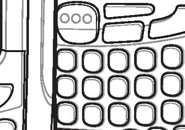
 Scan/Action Button Volume Up/Down Button Microphone Keypad (Alpha-Numeric Keypad Shown)")
19 Chapter 1 Getting Started Introduction This chapter lists the parts and accessories for the MC55 and explains how to set up the MC55 for the first time. Touch Screen with Protective Overlay Scan/Decode LED Charging/Battery Status LED Radio Status LED (MC5574 only) Scan/Action Button Volume Up/Down Button Microphone Keypad (Alpha-Numeric Keypad Shown) Power Button I/O Connector Figure 1-1 MC55 Front View
20 1-2 MC55 User Guide Battery Battery Latch Handstrap Speaker Camera Flash Camera Stylus Stylus Clip Action Button Exit Window Scan/Action Button Figure 1-2 MC55 Rear View Unpacking Carefully remove all protective material from the MC55 and save the shipping container for later storage and shipping. Verify that you received the following: MC55 EDA 2400 mah Lithium-ion battery stylus with tether (installed) screen protector, installed on display window Regulatory Guide Quick Start Guide. Inspect the equipment for damage. If any equipment is missing or damaged, contact the Motorola Enterprise Mobility Support center immediately. See page xv for contact information. Prior to using the MC55 for the first time, remove the protective shipping film that covers the scan window, display and camera window.
21 Getting Started 1-3 Accessories Table 1-1 lists the accessories available for the MC55 EDA. Table 1-1 MC55 Accessories Cradles Accessory Part Number Description Single Slot USB Cradle CRD UR Charges the MC55 main battery and a spare battery. Synchronizes the MC55 with a host computer through a USB connection. Four Slot Charge Only Cradle CRD CR Charges up to four MC55 devices. Four Slot Ethernet Cradle CRD ER Charges up to four MC55 devices and connects the MC55 with an Ethernet network. Vehicle Cradle VCD R Installs in a vehicle and charges the MC55 main battery. Vehicle Holder VCH R Provides an alternative mounting solution for the MC55 in a vehicle. Requires the Auto Charge cable for charging the MC55 battery. Chargers Four Slot Spare Battery Charger SAC CR Charges up to four MC55 battery packs. USB Charging Cable R Provides power to the MC55 and USB communication with a host computer. Charge Only Cable R Connects to a power supply to provide power to the MC55. Auto Charge Cable VCA R Charges the MC55 using a vehicle s cigarette lighter. Miscellaneous Spare 2400 mah lithium-ion battery Spare 3600 mah lithium-ion battery BTRY-MC55EAB00 BTRY-MC55EAB02 Replacement 2400 mah battery. Optional 3600 mah battery. Belt Mounted Rigid Holster SG-MC R Clips onto belt to hold the MC55 when not in use. Fabric Holster SG-MC R Soft holder for added protection. Stylus Spring Loaded Stylus KT R KT R STYLUS R STYLUS R Replacement stylus (3-pack). Replacement stylus (50-pack). Optional spring loaded stylus (3-pack). Optional spring loaded stylus (10-pack). Wall Mounting Kit R Use for wall mounting the four slot cradles. Screen Protector KT R Package of 3 screen protectors. Software - Enterprise Mobility Developer Kits (EMDKs), available at:
22 1-4 MC55 User Guide Getting Started To start using the MC55 for the first time: Install a microsd card (optional) Install the SIM card (MC5574 only) Install the main battery pack. Charge the MC55. Power on the MC55. Installing a microsd Card The microsd card slot provides secondary non-volatile storage. The slot is located under the battery pack. Refer to the documentation provided with the card for more information, and follow the manufacturer s recommendations for use. CAUTION Follow proper ESD precautions to avoid damaging the SD card. Proper ESD precautions include, but are not limited to, working on an ESD mat and ensuring that the operator is properly grounded. To install the microsd card: 1. Lift rubber access door. 2. Slide the SIM card holder door up to unlock. 3. Lift SIM card holder door. Rubber access door SIM card holder door microsd card holder door Figure 1-3 Lift SIM Slot Holder Door 4. Lift microsd card holder door. 5. Insert the microsd card into card holder door ensuring that the card slides into the holding tabs on each side of the door.
23 Getting Started 1-5 microsd card Holding tab Figure 1-4 Insert microsd Card in Holder 6. Close the card holder door and push down until it is securely into place. 7. Close SIM card holder door and slide down until it locks into place. 8. Close rubber access door. Installing the SIM Card NOTE MC5574 configuration only. GSM phone service requires a Subscriber Identification Module (SIM) card, or smart card. Obtain the card from the your service provider. The card fits into the MC55 and can contain the following information: Mobile phone service provider account details. Information regarding service access and preferences. Contact information, which can be moved to Contacts on the MC55. Any additional services to which you have subscribed. NOTE For more information about SIM cards, refer to the service provider's documentation. To install the SIM card: 1. Lift rubber access door. 2. Slide the SIM card holder up to unlock. 3. Lift the SIM card holder door.
24 1-6 MC55 User Guide Figure 1-5 Lifting the SIM Cover 4. Insert the SIM card, as shown in Figure 1-6 ensuring that the card slides into the holding tabs on each side of the door. Figure 1-6 Inserting the SIM Card 5. Close SIM card holder door and slide down to lock into place. 6. Close the rubber access door. 7. Install the battery. NOTE For detailed information about WWAN activation and settings, refer to the MC55 Integrator Guide. Installing the Battery NOTE The MC55 ships with either a 2400 mah or 3600 mah battery. The 2400 mah battery is shown in this installation procedure. To install the battery. 1. Insert the battery, bottom first, into the battery compartment in the back of the MC Press the battery down into the battery compartment until the battery release latch snaps into place.
25 Getting Started 1-7 Battery Release Latch Battery 2 1 Figure 1-7 Inserting the Battery The MC55 powers up automatically after inserting the battery if the battery has been charged previously. Charging the Battery CAUTION Ensure that you follow the guidelines for battery safety described in Battery Safety Guidelines on page 7-2. Charging the Main Battery Before using the MC55 for the first time, charge the main battery until the amber Charging/Battery Status LED remains lit (see Table 1-2 on page 1-8 for charge status indications). To charge the MC55, use a cable or a cradle with the appropriate power supply. For information about the accessories available for the MC55, see Chapter 6, Accessories. For cable and cradle setup and charging procedures refer to the MC55 Integrator Guide. USB Charging Cable Charge Only Cable Single Slot USB Cradle Four Slot Charge Only Cradle Four Slot Ethernet Cradle. To charge the main battery: 1. Connect the charging accessory to the appropriate power source. 2. Insert the MC55 into a cradle or attach to a cable. The MC55 begins charging. The Charging/Battery Status LED blinks amber while charging, then turns solid amber when fully charged. See Table 1-2 for charging indications.
26 1-8 MC55 User Guide The 2400 mah battery fully charges in less than four hours and the 3600 mah battery charges in less than six hours. Table 1-2 LED Charge Indicators Charging/Battery Status LED Indication Off Slow Blinking Amber (1 blink every 2 seconds) Solid Amber Fast Blinking Amber (2 blinks/second) Single Blink Amber (when Power button pressed) Blinking Amber (when Power button pressed) MC55 is not charging. MC55 is not inserted correctly in the cradle or connected to a power source. Charger/cradle is not powered. MC55 is charging. Charging complete. Note: When the battery is initially inserted in the MC55, the amber LED flashes once if the battery power is low or the battery is not fully inserted. Charging error, e.g.: Temperature is too low or too high. Charging has gone on too long without completion (typically eight hours). Battery depleted. Battery over-temperature condition. Charging Spare Batteries See Chapter 6, Accessories for information on using accessories to change spare batteries. Charging Temperature Charge batteries in temperatures from 0 C to 40 C (32 F to 104 F). Note that charging is intelligently controlled by the MC55. To accomplish this, for small periods of time, the MC55 or accessory alternately enables and disables battery charging to keep the battery at acceptable temperatures. The MC55 or accessory indicates when charging is disabled due to abnormal temperatures via its LED. See Table 1-2. Powering On the MC55 After inserting the battery or when turning the MC55 on for the first time, the splash screen displays for about a minute as the MC55 initializes its flash file system, then the calibration window appears. Note that these windows also appear upon cold boot. Calibrating the Screen NOTE The Calibration screen can be accessed by pressing Blue key then Backspace key. To calibrate the screen so the cursor on the touch screen aligns with the tip of the stylus: 1. Remove the stylus from its holder on the side of the MC Carefully press and briefly hold the tip of stylus on the center of each target that appears on the screen.


27 Getting Started Repeat as the target moves around the screen, then tap the screen to continue. Checking Battery Status NOTE To check battery status, remove the MC55 from any AC power source (cradle, cables, etc.) To check the charge status of the main battery in the MC55, tap Start > Settings > System tab > Power icon to display the Power window. To save battery power, tap the Advanced tab and set the MC55 to turn off after a specified number of minutes. Replacing the Battery 1. Press the red Power button to suspend the MC Use finger or stylus to slide the battery latch to the right releasing the battery. The battery ejects slightly. Battery Latch Figure 1-8 Removing the Battery 3. Lift the battery from the MC Insert the replacement battery, bottom first, into the battery compartment in the back of the MC Press the battery down until the battery release latch snaps into place. The MC55 powers up after inserting the battery. Removing the microsd Card To remove an microsd card: 1. Press the red Power button to suspend the MC Remove the battery. 3. Lift the rubber access door.
28 1-10 MC55 User Guide 4. Slide SIM card holder door up to unlock. 5. Lift SIM Card holder door. 6. Lift the microsd card holder door. 7. Remove microsd card from holder. 8. Close microsd card holder door. 9. Close SIM card holder door. 10. Slide SIM card holder door down to lock into place. 11. Close the rubber access door. 12. Replace the battery. Battery Management Observe the following battery saving tips: Leave the MC55 connected to AC power at all times when not in use. Set the MC55 to turn off after a short period of non-use. Set the backlight to turn off after a short period of non-use. Turn off all wireless activities when not in use. Changing the Power Settings To set the MC55 to turn off after a short period of non-use: 1. Tap Start > Settings > System tab > Power icon > Advanced tab. 2. Select the On battery power: Turn off device if not used for check box and select a value from the drop-down list. 3. Select ok. Changing the Backlight Settings To change the backlight settings in order to conserve more battery power: 1. Tap Start > Settings > System tab > Backlight icon > Battery Power tab. 2. Select the Disable backlight if device is not used for check box and select a value from the drop-down list. 3. Select the Brightness tab. 4. Tap the Disable backlight check box to turn off the display backlight, or use the slider to set a low value for the backlight. 5. Select ok.

29 Getting Started 1-11 Changing the Keypad Backlight Settings To change the keypad backlight settings in order to conserve more battery power: 1. Tap Start > Settings > System tab > Keylight icon > Battery Power tab. 2. Select the On battery power: Disable keylight if device if not used for check box and select a value from the drop-down list. 3. Select the Advanced tab. 4. Tap the Disable keylight check box to turn off the keypad backlight. 5. Select ok. Turning Off the Radios Windows Mobile 6.1 devices include Wireless Manager, which provides a simple method of enabling, disabling, and configuring all the device s wireless capabilities in one place. To open Wireless Manager, tap the Connectivity icon or tap Wireless Manager on the Today screen. Connectivity icon Figure 1-9 Opening Wireless Manager Select Wireless Manager.
30 1-12 MC55 User Guide Figure 1-10 Wireless Manager Window NOTE Wireless connection options vary depending upon configurations. To enable or disable a wireless connection, tap the specific button. To enable or disable all wireless connections, tap and hold the All button. To configure settings for a connection, tap Menu. Figure 1-11 Wireless Manager Menu
31 Getting Started 1-13 Handstrap Replacement Depending upon the configuration, there are two possible handstrap designs: with handstrap bracket with handstrap clip. With Handstrap Clip Removal To remove a handstrap from the MC55: 1. Slide the handstrap clip out of the handstrap slot. Figure 1-12 Handstrap Clip Removal 2. Remove the battery. CAUTION When removing handstrap pin, be carefully not to damage handstrap mounting area. 3. Using a small flat screwdriver, push the head of the screwdriver between the handstrap pin and the bottom of the housing as shown below. 4. Pry the handstrap and pin up and out of the handstrap mount area.
32 1-14 MC55 User Guide Figure 1-13 Handstrap and Pin Removal 5. Repeat for the other side of the handstrap. 6. Remove pin from the handstrap. Figure 1-14 Pin Removal 7. Pull handstrap through handstrap slot. Installation To install a new handstrap: 1. Feed bottom end of handstrap into handstrap slot on the bottom of the MC55.
33 Getting Started 1-15 Figure 1-15 Feed handstrap into Handstrap Slot 2. Slide pin into bottom of handstrap. 3. Center the pin in the handstrap loop. NOTE Handstrap and pin should fit securely into the handstrap mounting area. When pulling on handstrap use enough force to engage pin into place. 4. Pull handstrap so that the pin and bottom of handstrap slide into position in the mounting area. Figure 1-16 Pin and Handstrap in Mounting Area Figure 1-17 Slide Handstrap and Tether Over Handstrap Mount 5. Slide tether loop over handstrap. 6. Insert the handstrap clip into the slot on the device. Ensure that it is securely in place.
34 1-16 MC55 User Guide With Handstrap Bracket Removal To remove a handstrap from the MC55: 1. Pull up on the handstrap to remove the handstrap bracket from the end cap. Figure 1-18 Handstrap Bracket Removal 2. Remove the battery. CAUTION When removing handstrap pin, be carefully not to damage handstrap mounting area. 3. Using a small flat screwdriver, push the head of the screwdriver between the handstrap pin and the bottom of the housing as shown below. 4. Pry the handstrap and pin up and out of the handstrap mount area.
35 Getting Started Figure 1-19 Handstrap and Pin Removal 5. Repeat for the other side of the handstrap. 6. Remove pin from the handstrap. Figure 1-20 Pin Removal 7. Pull handstrap through handstrap slot. Installation To install a new handstrap: 1. Feed bottom end of handstrap into handstrap slot on the bottom of the MC55.
36 1-18 MC55 User Guide Figure 1-21 Feed handstrap into Handstrap Slot 2. Slide pin into bottom of handstrap. 3. Center the pin in the handstrap loop. NOTE Handstrap and pin should fit securely into the handstrap mounting area. When pulling on handstrap use enough force to engage pin into place. 4. Pull handstrap so that the pin and bottom of handstrap slide into position in the mounting area. Figure 1-22 Pin and handstrap in Mounting Area 5. Slide handstrap mount through the loop at the top of handstrap. Figure 1-23 Slide Handstrap and Tether Over Handstrap Mount 6. Slide tether loop over handstrap mount. 7. Align handstrap mount with mounting holes at the top of the MC55.
37 Getting Started 1-19 Figure 1-24 Align Mount Bracket with Holes in End Cap 8. Push the handstrap mount down until it snaps into position.
38 1-20 MC55 User Guide
39 Chapter 2 Using the MC55 Introduction This chapter explains the buttons, status icons, and controls on the MC55, and provides basic instructions for using the MC55, including powering on and resetting the MC55, and entering and capturing data. Today Screen The Today screen displays important information, such as upcoming appointments and status indicators. Tap a section on the screen to open the associated program. Alternatively, tap Start > Today to display the Today screen. Connectivity Notification Open the Start Menu Change the date and time WAN Signal Strength Adjust volume Battery Status Change the date and time, set up the alarm, and more Turn on or off radios Command Bar Wireless Applications BTExplorer Soft Keys Figure 2-1 Today Screen To customize the Today screen, tap Start > Settings > Today icon. Use the Appearance tab to customize the background and the Items tab to change the list and order of items that appear on the screen.
40 2-2 MC55 User Guide Status Icons The Navigation bar at the top of the screen can contain the status icons listed in Table 2-1. Table 2-1 Status Icons Icon Function Description Notification Notification that one or more instant messages were received. Notification that one or more /text messages were received. Notification that one or more voice messages were received. There are more notification icons than can be displayed. Tap to display remaining icons. Indicates a reminder of an upcoming calendar event. Connectivity Connection is active. Connection is not active. Synchronization is occurring. Wi-Fi available. Wi-Fi in use. GPRS available. (MC5574 only) GPRS connecting. (MC5574 only) EGPRS available. (MC5574 only) EGPRS connecting. (MC5574 only) WAN (MC5574 only) Call missed. Dialing while no SIM card is installed. Voice call in progress. Calls are forwarded. Call on hold. Speakerphone is on. Antenna/signal icon: wireless on/good signal. Antenna/signal icon: wireless off. Antenna/signal icon: no service or searching. GPRS in use. EGPRS in use. Roaming. SIM Card not installed.
41 Using the MC Table 2-1 Status Icons (Continued) Icon Function Description Speaker All sounds are on. All sounds are off. Battery Main battery is charging. Main battery level. Main battery is low or very low. Battery power critically low. Time and Next Appointment Displays current time in analog or digital format. The command bar at the bottom of the screen can contain the task tray icons listed in Table 2-2. Table 2-2 Task Tray Icons Icon Description Wireless connection status Out-of-network range (not associated) No wireless LAN network card detected Bluetooth Enabled Indicates WLAN signal strength. Indicates no wireless LAN network connection. Notify the network administrator. Indicates Wireless LAN disabled or radio disabled. Notify the network administrator. Indicates the Bluetooth radio is on. (Available when StoneStreet One Bluetooth stack is enabled.) Bluetooth Disabled Indicates the Bluetooth radio is off. (Available when StoneStreet One Bluetooth stack is enabled.) Bluetooth Connection ActiveSync USB Client Mode Indicates the Bluetooth radio is connected to another Bluetooth device. (Available when StoneStreet One Bluetooth stack is enabled.) Indicates an active serial connection between the MC55 and the host computer. Indicates that the MC55 is in USB Client mode. USB Host Mode Indicates that the MC55 is in USB Host mode.
42 2-4 MC55 User Guide Programs Table 2-3 lists the default programs on the Start menu. Table 2-3 Programs in the Start Menu Icon Name Description Office Mobile Calendar Use the complete suite of Microsoft Office applications for your mobile device. Excel Mobile - Create new workbooks or view and edit Microsoft Excel workbooks. OneNote Mobile - Create new notes or view existing notes. PowerPoint Mobile - View Microsoft PowerPoint slides and presentations. Word Mobile - Create, view, and edit Microsoft Word documents. Keep track of appointments and create meeting requests. Contacts Keep track of friends and colleagues. Internet Explorer Mobile Browse Web and WAP sites as well as download new programs and files from the Internet. Messaging Send and receive and text messages. Phone Make and receive calls, switch between calls, and set up conference calling. Help See Help topics for the current screen or program. Table 2-4 lists programs that are listed in the Programs window. Table 2-4 Programs in Program Window Icon Name Description ActiveSync Synchronize information between the MC55 and a host computer or the Exchange Server. AirBEAM Allows specially designed software packages to be transferred between a host server and the MC55. Refer to the MC55 Integrator Guide for more information.
43 Using the MC Table 2-4 Programs in Program Window (Continued) Icon Name Description BTExplorer Manages Bluetooth connections. Calculator Perform basic arithmetic and calculations, such as addition, subtraction, multiplication, and division. File Explorer Organize and manage files on your device. GetGood Link to download Good Mobile Messaging software. Getting Started Internet Sharing Provides quick links for setting the devices clock, setting up , setting a device password, setting a background image and transferring music. Connect a notebook computer to the Internet using the MC55's data connection. Messenger Use this mobile version of Windows Live Messenger. MSP Agent Notes Interacts with MSP agents to collect monitoring and asset information to enable the configuration, provisioning, monitoring and troubleshooting of the MC55. Refer to the Mobility Services Platform 3.2 User Guide for more information. Create handwritten or typed notes, drawings, and voice recordings. Pictures & Videos View and manage pictures, animated GIFs, and video files. Rapid Deployment Client Remote Desktop Mobile Facilitates software downloads from a Mobility Services Platform Console FTP server to the MC55. Refer to the Mobility Services Platform 3.2 User Guide for more information. Log onto Windows NT server type computers and use all of the programs that are available on that computer from the MC55. Search Search contacts, data, and other information on your MC55. Task Manager Enables viewing of memory and CPU allocations and stops running processes.
44 2-6 MC55 User Guide Table 2-4 Programs in Program Window (Continued) Icon Name Description SIM Toolkit Manage the contacts that are stored on your SIM card. Copy SIM contents to Contacts on the MC55. Tasks Keep track of your tasks. Windows Live Use this mobile version of Windows Live to find information on the web. Windows Media Play back audio and video files. Settings Table 2-5 lists control applications pre installed on the MC55. Tap Start > Settings to open the Settings window. Table 2-5 Settings in the Setting Window Icon Name Description Personal Tab Buttons Assign a program to a button. Input Set options for each of the input methods. Lock Set a password for the MC55. Menus Set what programs appear in the Start menu. Owner Information Enter personal information on the MC55. Phone Make and receive calls, switch between calls, and set up conference calling. Sounds & Notifications Enable sounds for events, notifications, and more, and set the type of notification for different events.
45 Using the MC Table 2-5 Settings in the Setting Window (Continued) Icon Name Description Today Customize the appearance and the information to be displayed on the Today screen. System Tab About Backlight View basic information such as the Windows Mobile version and type of processor used on the MC55. Set the display backlight time-out and adjust brightness. Certificates See information about certificates installed on the MC55. Clock & Alarms Customer Feedback Set the device clock to the date and time of your locale or to a visiting time zone when you re traveling. Alarms can also be set at specified days and times of a week. Submit feedback on the Windows Mobile 6.1 software. Encryption Allow files on a storage card to be encrypted. Encrypted files are readable only on your device. Error Reporting External GPS GPS Setup Enable or disable the device's error reporting function. When this function is enabled and a program error occurs, technical data about the state of the program and your computer is logged in a text file and delivered to Microsoft's technical support if you choose to send it. Set the appropriate GPS communication ports, if required. You may need to do this when there are programs on your device that access GPS data or you have connected a GPS receiver to the MC55. View GPS SUPL information. Keylight Set the keypad backlight time-out. Managed Programs Lists applications that have been installed remotely by your system administrator. Memory Check the device memory allocation status and memory card information.
46 2-8 MC55 User Guide Table 2-5 Settings in the Setting Window (Continued) Icon Name Description Phone Info Displays the phone version information. Power Check battery power and set the time-out for turning off the display to conserve battery power. Regional Settings Set the regional configuration to use, including the format for displaying numbers, currency, date, and time on the MC55. Remove Programs Remove programs that you installed on the MC55. Screen Change the screen orientation, re-calibrate the screen, and change the screen text size. System Info Displays the MC55 s software and hardware information. Task Manager Enables viewing of memory and CPU allocations and stops running processes. Windows Update Link to Microsoft's web site and update Windows Mobile on your device with the latest security patches or fixes. Do not use. Obtain updates from Motorola. Connections Tab Beam Set the device to receive incoming IrDA beams. (Not supported on the MC55.) Connections Domain Enroll Set up one or more types of modem connections for your device, such as phone dial-up, GPRS, Bluetooth, and more, so that your device can connect to the Internet or a private local network. Make your device an AD domain member for device management and security. USB to PC Enables or disables the enhanced network connectivity. Wi-Fi Setup wireless network connection and customize settings. Wireless Manager Enables or disables the MC55 s wireless radios and customizes Wi-Fi and Bluetooth and Phone settings.


47 Using the MC Adjusting Volume To adjust the system volume using the Speaker icon in the navigation bar: 1. Tap the Speaker icon. The Volume dialog box appears. Figure 2-2 Volume Dialog Box 2. Tap and move the slide bar to adjust the volume. 3. Select the On or Off radio button to turn the volume on or off. You can also adjust the system volume using the Sounds & Notifications window, or use the Up/Down button on the side of the MC55. Battery Status Indications Battery icons appear on the navigation bar indicating the battery power level. When the main battery power falls below a predetermined level the icon indicates the status and a battery dialog box appears indicating the status of the battery. Figure 2-3 Battery Status Dialog Box The Battery icon always appears in the navigation bar when the Today screen is visible. The icon indicates the battery power level. The message displays until the Dismiss button is pressed.


48 2-10 MC55 User Guide Figure 2-4 Battery Icon on the Title Bar Also view the battery status using the Power window. Either: Tap the Battery icon Tap Start > Settings > System tab > Power icon. Figure 2-5 Settings Power Window Battery Reserve Options If the charge of the battery reaches a critical threshold, the MC55 shuts down. This threshold can be changed but affects the amount of time that data can be retained. 1. Tap Start > Settings > System tab > Power icon > RunTime tab. A warning message appears. Figure 2-6 Warning Message 2. Read the warning message and tap ok.

49 Using the MC Figure 2-7 RunTime Tab 3. Select one of the Battery Reserve Options. Option 1: Minimum - After a low battery shutdown, data will be retained for minimum amount of time. Battery should be replaced immediately to avoid data loss. Option 2: Less - After a low battery shutdown, data will be retained for less than normal amount of time. Option 3: Normal - After a low battery shutdown, data will be retained for maximum amount of time. 4. Tap ok. Main Battery Temperature Notifications The temperature notification system implements three levels of notification when the temperature within the battery exceeds specific temperature thresholds: Level 1: Temperature Watch; this level is similar to main battery low warning. It indicates that the battery temperature has reached the first threshold level. The user should move to an environment within proper operating temperature. Level 2: Temperature Warning; this level is similar to main battery very low warning. It indicates the battery temperature has reached the second threshold level. The user should close all running applications and stop using the MC55. Level 3: Temperature Error; this level indicates the battery has reached an unusable temperature threshold and immediately suspends the MC55. This level does not have any graphical notification associated with it. Figure 2-8 Main Battery Temperature Watch Dialog Box
50 2-12 MC55 User Guide Figure 2-9 Main Battery Temperature Warning Dialog Box NOTE The Temperature Warning dialog box remains visible until you tap Hide. LED Indicators The MC55 has three LED indicators. The Scan/Decode LED indicates status for scanning. The Charging/Battery Status LED indicates battery charging and status.the Radio Status LED indicates WWAN radio status. Table 2-6 describes the LED indications. Scan/Decode LED Charging/Battery Status LED Radio Status LED Figure 2-10 LED Indicators Table 2-6 LED Indications LED State Indication Scan/Decode LED Solid Green Solid Red Off Successful decode/capture. Laser enabled, scanning/imaging in process. Not enabled. Charging/Battery Status LED Slow Blinking Amber Solid Amber Main battery in MC55 is charging. Main battery in MC55 is fully charged.
51 Using the MC Table 2-6 LED Indications (Continued) LED State Indication Fast Blinking Amber Off Single Blink Amber (when Power button pressed) Blinking Amber (when Power button pressed) Charging error. Not charging. Battery depleted. Battery over-temperature condition. Radio Status LED (MC5574 only) Slow Blinking Green Off RF (WWAN) activity. No RF activity. NOTE For information about scanning/decoding, see Data Capture on page For information about WWAN radio status and settings, see Chapter 4, Using the Phone, or refer to the MC55 Integrator Guide. Resetting the MC55 There are two reset functions, warm boot and cold boot. A warm boot restarts the MC55 by closing all running programs. A cold boot also restarts the MC55, and also initializes some drivers. Data saved in flash memory or a memory card is not lost. If the MC55 is not functioning properly, perform a warm boot first. If the MC55 still does not respond, perform a cold boot. Performing a Warm Boot Hold down the red Power button for approximately five seconds. As soon as the MC55 starts to boot (splash screen displays) release the Power button. Performing a Cold Boot To perform a cold boot: On a numeric keypad, simultaneously press the red Power button and the and keys. On an alphanumeric keypad, simultaneously press the red Power button and the and keys. On an PIM keypad, simultaneously press the red Power button and the and keys. Waking the MC55 The wake-up conditions define what actions wake up the mobile computer after it has gone into suspend mode. The mobile computer can go into suspend mode by either pressing the Power button or automatically by Control
52 2-14 MC55 User Guide Panel time-out settings. These settings are configurable and the factory default settings are shown in Table 2-7 are subject to change/update. Table 2-7 Wake-up Default Settings Condition for Wake-up Power Button Automatic Time-out AC power is applied. No Yes Mobile computer is inserted into a cradle. No Yes Mobile computer is removed from a cradle. No Yes Mobile computer is connected to a USB device. No Yes Mobile computer is disconnected from a USB device. No Yes A key is pressed. No Yes The scan triggered is pressed. No Yes The screen is touched. No No Bluetooth communication Yes Yes Incoming phone call Yes Yes Locking the MC55 You can lock the MC55 by disabling key presses and screen tap or by requiring a password. Keypad Locking Locking the MC55 turns off keyboard and touch screen functionality. This is helpful when the MC55 is turned on and you want to prevent accidental key presses. To lock the device, tap the Device unlocked icon. The icon changes to locked. Device Unlocked Icon Device Locked Icon Figure 2-11 Device Locked/Unlocked Icons To unlock the device and free it for use, tap Unlock.


53 Using the MC Figure 2-12 Unlock Device Window Tap Unlock on the Unlock window. NOTE You can make emergency calls even when the MC55 is locked. See Making an Emergency Call on page 4-8 for more information. Password Locking Use the Password window to set a password to disable unauthorized access to the MC55. NOTE If the device is configured to connect to a network, use a strong (difficult to figure out) password to help protect network security. Password cracking tools continue to improve and the computers used to crack passwords are more powerful than ever. 1. Tap Start > Settings > Personal tab > Lock icon > Password tab. Figure 2-13 Password Window - Password Tab 2. Select Prompt if device unused for check box to enable password protection. 3. From the drop-down list, select a time value for the protection to take affect after non-use. 4. From the Password type: drop-down list, select either Simple PIN or Strong alphanumeric. 5. For a simple password, enter a four-digit password in the Password field. For a stronger password:


54 2-16 MC55 User Guide a. Enter a seven character password in the Password: field. A strong password must contain at least seven characters and contain at least three of the following: uppercase and lowercase letters, numerals, and punctuation. b. Re-enter the password in the Confirm: field. 6. Tap ok. 7. To set a hint to remember the password, tap the Hint tab. Figure 2-14 Password Window - Hint Tab 8. In the text box, enter a hint for a password reminder. 9. Tap ok. When the MC55 is not used for a period of time and the user tries to access the device, the Password window appears. Figure 2-15 Enter Password Windows Enter the password to un-lock the device. Tap Unlock.
55 Using the MC Keypads The MC55 offers three types modular keypad configurations: Numeric, alpha-numeric and PIM. Numeric Keypad Configuration The numeric keypad contains application keys, scroll keys, and function keys. The keypad is color-coded to indicate the alternate function key (blue) values. Note that an application can change keypad functions so the MC55 s keypad may not function exactly as described. See Table 2-8 for key and button descriptions and Table 2-9 on page 2-20 for the keypad s special functions. Figure 2-16 MC55 Numeric Keypad Table 2-8 MC55 Numeric Keypad Descriptions Blue Key Key Description Use this key to launch applications or access items (shown on the keypad in blue). Press the Blue key once to activate this mode, followed by another key. A single press illuminates the key and displays the following icon at the bottom of the screen, until a second key is pressed: Orange Key Use this key to access the secondary layer of characters and actions (shown on the keypad in orange). Press the Orange key once to lock the keypad into Alpha state. A single press illuminates the key and displays the following icon at the bottom of the screen: Press the Orange key a second time to return to the normal state. Press the Orange key, then the Shift key to add a temporary shift (that applies only to the next key pressed) to the orange lock state. This displays the following icon at the bottom of the screen:
56 2-18 MC55 User Guide Table 2-8 MC55 Numeric Keypad Descriptions (Continued) Key Talk/Start Menu Description Talk (Green Phone): press to display the phone keypad window or to dial a phone number (from the phone keypad window). When on a phone call, press to place the call on hold. Use this key in conjunction with the Blue key to instantly display the Start menu from any application without tapping the screen. This function is user programmable. MC5590: To use a key as an application key (APP key) on the keyboard, create and install a new keyboard remap table. However, to remap the green phone key as APP keys through the registry, create an XML provisioning file that includes the following entry: <characteristic type= HKLM\Hardware\DeviceMap\KYBD > <parm name= GreenKeyOverride value= xx datatype= integer /> [where xx is the new APP key code] Provision the file to the MC55 to send an APP key code, instead of the original key code, upon pressing the green phone key. Refer to the MC55 Integrator Guide for information on creating XML provisioning files. Scan (yellow) Activates the scanner/imager in a scan enabled application. End/OK End (Red Phone): press when the phone keypad window displays to stop dialing or end a call. Use this key in conjunction with the Blue key as an OK or close button. This function is user programmable. To use a key as an application key (APP key) on the keyboard, create and install a new keyboard remap table. However, to remap the red phone keys as APP keys through the registry, create an XML provisioning file that includes the following entry: <characteristic type= HKLM\Hardware\DeviceMap\KYBD > <parm name= RedKeyOverride value= yy datatype= integer /> [where yy is the new APP key code] Provision the file to the MC55 to send an APP key code, instead of the original key code, upon pressing the red phone key. Refer to the MC55 Integrator Guide for information on creating XML provisioning files. Scroll Up and Left Moves up one item. Moves left one item when pressed with the Orange key. Scroll Down and Right Moves down one item. Moves right one item when pressed with the Orange key.
57 Using the MC Table 2-8 MC55 Numeric Keypad Descriptions (Continued) Soft Keys Key Description Accesses the command or menu above it on the screen. Star Produces an asterisk in default state. Press and release the blue key, then press the Star key to open the Start menu. Alphanumeric Backspace In default state, produces the numeric value on the key. In Alpha state, produces the lower case alphabetic characters on the key. Each key press produces the next alphabetic character in sequence. For example, press and release the Orange key and then press the 4 key once to produce the letter g ; press and release the Orange key and then press the 4 key three times to produce the letter i. Press the SHIFT key in Alpha state to produce the upper case alphabetic characters on the key. For example, press and release the Orange key, press and release the SHIFT key, and then press the 4 key once to produce the letter G ; press and release the Orange key, press and release the SHIFT key and then press the 4 key three times to produce the letter I. Produces a backspace. SHIFT Press and release the SHIFT key to activate the keypad alternate SHIFT functions. A single press displays the following icon at the bottom of the screen, until a second key is pressed: Press the Orange key, then the Shift key to add a temporary shift (that applies only to the next key pressed) to the orange lock state. This displays the following icon at the bottom of the screen: Enter Executes a selected item or function.
58 2-20 MC55 User Guide Table 2-9 Numeric Keypad Input Modes Key Numeric Mode Blue+ Key SHIFT + Key Orange Key (Alpha Lowercase Mode) 1st Press 2nd Press 3rd Press 4th Press Orange + Shift Keys (Alpha Uppercase Mode) 1st Press 2nd Press 3rd Press 4th Press 1 1 F1! * * * * * * * * 2 2 a b c A B C 3 3 F3 # d e f D E F 4 4 F4 $ g h i G H I 5 5 F5 % j k l J K L 6 6 F6 ^ m n o M N O 7 7 F7 & p q r s P Q R S 8 8 F8 * t u v T U V 9 9 F9 ( w x y z W X Y Z 0 0 F10 ). > Up Up Up Hilight Up Down Down Down Hilight Down Left Right Left Right Enter Action Action Action Action Action Note: An application can change the key functions. The keypad may not function exactly as described. Alpha-numeric Keypad Configurations The three types of alpha-numeric keypads (QWERTY, AZERTY and QWERTZ) produce the 26-character alphabet (A-Z, both lowercase and uppercase), numbers (0-9), and assorted characters. The keypad is color-coded to indicate which modifier key to press to produce a particular character or action. The keypad default is alphabetic, producing lowercase letters. See Table 2-10 for key and button descriptions and Table 2-11 on page 2-24 for the keypad s special functions. AZERTY keypad is used on configurations installed with the French operating system. QWERTZ keypad is used on configurations installed with the German operating system.
59 Using the MC ok Figure 2-17 QWERTY Keypad Configuration ok Figure 2-18 AZERTY Keypad Configuration ok Figure 2-19 QWERTZ Keypad Configuration
60 2-22 MC55 User Guide Table 2-10 Alpha-numeric Keypad Descriptions Key Action Blue Key Orange Key Talk/Start Menu Press the Blue key once to activate this mode temporarily, followed by another key. This displays the following icon at the bottom of the screen, until a second key is pressed: Press the Blue key twice to lock this mode. This displays the following icon at the bottom of the screen: Press the Blue key a third time to unlock. Accesses the secondary layer of characters and actions (shown on the keypad in orange). Press the Orange key once to activate this mode temporarily, followed by another key. This displays the following icon at the bottom of the screen, until a second key is pressed: Press the Orange key twice to lock this mode. This displays the following icon at the bottom of the screen: Press the Orange key a third time to unlock. Talk (Green Phone): press to display the phone keypad window or to dial a phone number (from the phone keypad window). When on a phone call, press to place the call on hold. Use this key in conjunction with the Blue key to instantly display the Start menu from any application without tapping the screen. This function is user programmable. To use a key as an application key (APP key) on the keyboard, create and install a new keyboard remap table. However, to remap the green phone key as APP keys through the registry, create an XML provisioning file that includes the following entry: <characteristic type= HKLM\Hardware\DeviceMap\KYBD > <parm name= GreenKeyOverride value= xx datatype= integer /> [where xx is the new APP key code] Provision the file to the MC55 to send an APP key code, instead of the original key code, upon pressing the green phone key. Refer to the MC55 Integrator Guide for information on creating XML provisioning files. Scan (yellow) Activates the scanner/imager in a scan enabled application.
61 Using the MC Table 2-10 Alpha-numeric Keypad Descriptions (Continued) Key Action End/OK ok End (Red Phone): press when the phone keypad window displays to stop dialing or end a call. Use this key in conjunction with the Blue key as an OK or close button. This function is user programmable. MC5590: To use a key as an application key (APP key) on the keyboard, create and install a new keyboard remap table. However, to remap the green phone key as APP keys through the registry, create an XML provisioning file that includes the following entry: <characteristic type= HKLM\Hardware\DeviceMap\KYBD > <parm name= RedKeyOverride value= yy datatype= integer /> [where yy is the new APP key code] Provision the file to the MC55 to send an APP key code, instead of the original key code, upon pressing the red phone key. Refer to the MC55 Integrator Guide for information on creating XML provisioning files. Scroll Up and Left Moves up one item. Moves left one item when pressed with the Orange key. Scroll Down and Right Moves down one item. Moves right one item when pressed with the Orange key. Soft Keys Accesses the command or menu above it on the screen. Shift Changes the state of the alpha characters from lowercase to uppercase. Press the Shift key to activate this mode temporarily, followed by another key. This displays the following icon at the bottom of the screen, until a second key is pressed: Press the Shift key twice to lock this mode. This displays the following icon at the bottom of the screen: Press the Shift key a third time to unlock. Backlight Turns the display backlight on and off. Backspace Produces a backspace.
62 2-24 MC55 User Guide Table 2-10 Alpha-numeric Keypad Descriptions (Continued) Key Action Enter Executes a selected item or function. Star Produces an asterisk. au Creates special characters. Table 2-11 QWERTY Keypad Input Modes Key Normal Shift + Key Orange + Key Blue + Key Q q Q * q W w W 1 w E e E 2 e R r R 3 r T t T + t Y y Y _ y U u U - u I i I = i O o O o P p P áü p A a A # a S s S 4 s D d D 5 d F f F 6 f G g G ( g H h H ) h J j J / j K k K : k Note: An application can change the key functions. The keypad may not function exactly as described.
63 Using the MC Table 2-11 QWERTY Keypad Input Modes (Continued) Key Normal Shift + Key Orange + Key Blue + Key L l L l Backspace Backspace Backspace Backspace Backspace Shift Shift Shift-Lock Shift Shift Z z Z 7 z X x X 8 x C c C 9 c V v V % v B b B & b N n N! n M m M? m,, ENTER Enter Enter Enter Enter 0 0 ) 0 0 TAB Tab Tab Back tab Tab SPACE Space Space Space Space Backlight Backlight Backlight Backlight Backlight. (Period). >.. Note: An application can change the key functions. The keypad may not function exactly as described. Table 2-12 AZERTY Keypad Input Modes Key Normal Shift + Key Orange + Key Blue + Key A a A * a Z z Z 1 z E e E 2 e R r R 3 r T t T + t Y y Y _ y U u U - u I i I = i O o O o Note: An application can change the key functions. The keypad may not function exactly as described.
64 2-26 MC55 User Guide Table 2-12 AZERTY Keypad Input Modes (Continued) Key Normal Shift + Key Orange + Key Blue + Key P p P áü p Q q Q # q S s S 4 s D d D 5 d F f F 6 f G g G ( g H h H ) h J j J / j K k K : k L l L l Backspace Backspace Backspace Backspace Backspace Shift Shift Shift-Lock Shift Shift W w W 7 w X x X 8 x C c C 9 c V v V % v B b B & b N n N! n M m M? m,, Enter Enter Enter Enter Enter 0 0 ) 0 0 TAB Tab Tab Back tab Tab SPACE Space Space Space Space Backlight Backlight Backlight Backlight Backlight. (Period). >.. Note: An application can change the key functions. The keypad may not function exactly as described.
65 Using the MC Table 2-13 QWERTZ Keypad Input Modes Key Normal Shift + Key Orange + Key Blue + Key Q q Q * q W w W 1 w E e E 2 e R r R 3 r T t T + t Z z Z _ z U u U - u I i I = i O o O o P p P áü p A a A # a S s S 4 s D d D 5 d F f F 6 f G g G ( g H h H ) h J j J / j K k K : k L l L l Backspace Shift Backspace Shift Y y Y 7 y X x X 8 x C c C 9 c V v V % v B b B & b N n N! n M m M? m,, Note: An application can change the key functions. The keypad may not function exactly as described.
66 2-28 MC55 User Guide Table 2-13 QWERTZ Keypad Input Modes (Continued) Key Normal Shift + Key Orange + Key Blue + Key ENTER Enter ENTER ENTER Enter 0 0 ) 0 0 TAB Tab Tab Back tab Tab SPACE Space Space Space Space Backlight Backlight Backlight Backlight Backlight. (Period). >.. Note: An application can change the key functions. The keypad may not function exactly as described. PIM Keypad Configuration The PIM keypad (only available on MC5590) contains application keys and scroll keys. Note that an application can change keypad functions so the MC55 s keypad may not function exactly as described. See Table 2-8 for key and button descriptions and Table 2-9 on page 2-20 for the keypad s special functions. Figure 2-20 MC55 PIM Keypad
67 Using the MC Table 2-14 MC55 PIM Keypad Descriptions Key Talk (Green Phone) Description This key is user programmable. To use a key as an application key (APP key) on the keyboard, create and install a new keyboard remap table. However, to remap the green phone key as APP keys through the registry, create an XML provisioning file that includes the following entry: <characteristic type= HKLM\Hardware\DeviceMap\KYBD > <parm name= GreenKeyOverride value= xx datatype= integer /> [where xx is the new APP key code] Provision the file to the MC55 to send an APP key code, instead of the original key code, upon pressing the green phone key. Refer to the MC55 Integrator Guide for information on creating XML provisioning files. End (Red Phone) This key is user programmable. To use a key as an application key (APP key) on the keyboard, create and install a new keyboard remap table. However, to remap the green phone key as APP keys through the registry, create an XML provisioning file that includes the following entry: <characteristic type= HKLM\Hardware\DeviceMap\KYBD > <parm name= RedKeyOverride value= yy datatype= integer /> [where yy is the new APP key code] Provision the file to the MC55 to send an APP key code, instead of the original key code, upon pressing the red phone key. Refer to the MC55 Integrator Guide for information on creating XML provisioning files. Scan (yellow) Activates the scanner/imager in a scan enabled application. Scroll Up Moves up one item. Scroll Down Moves up down item. Scroll Left Moves left one item.
68 2-30 MC55 User Guide Table 2-14 MC55 PIM Keypad Descriptions (Continued) Key Description Scroll Right Moves right one item. Soft Keys Accesses the command or menu above it on the screen. Enter Executes a selected item or function. OK Use this key as an OK or close button. Special Character Key NOTE Special characters are only available on the alpha-numeric keypad configurations. To add special characters using the MC55 áü key, type the related character first, then press the Orange twice followed by the áü (P) key. Continue pressing the áü key until the special character displays. To modify an existing character, move the cursor to the right of the character then press the Orange key twice and then press the áü key until the special character replaces the original character. Table 2-15 lists the special characters you can generate. Table 2-15 Special Characters Key Special Characters Key Special Characters a c d e i l n o p r s A C D E I L N O P R S
69 Using the MC Table 2-15 Special Characters (Continued) Key Special Characters Key Special Characters t u y z T U Y Z $ / ( ) +!. %, # & _? : -


70 2-32 MC55 User Guide Function Buttons The MC55 s buttons perform certain functions. Scan/Action Button Volume Up/Down Button Action Button Power Button Scan/Action Button Figure 2-21 Function Buttons Power: Press the red Power button to turn the MC55 screen on and off. The MC55 is in suspend mode when the screen is off. For more information, see Powering On the MC55 on page 1-8. Also use the Power button to reset the MC55 by performing a warm or cold boot. See Resetting the MC55 on page Scan/Action: Press to scan bar codes or capture images. See Data Capture on page Or, press to open an application or perform a function. See the Microsoft Applications for Mobile 6 User Guide to set an application to open. Volume Up/Down: Press to increase or decrease the MC55 s volume. Action: Press to open an application or perform a function. See the Microsoft Applications for Windows Mobile 6 User Guide to set an application to open. Stylus Use the MC55 stylus to select items and enter information. The stylus functions as a mouse. Tap: Touch the screen once with the stylus to press option buttons and open menu items. Tap and Hold: Tap and hold the stylus on an item to see a list of actions available for that item. On the pop-up menu that appears, tap the action to perform. Drag: Hold the stylus on the screen and drag across the screen to select text and images. Drag in a list to select multiple items. CAUTION To prevent damage to the screen, do not use any device other than the Motorola-provided stylus.

71 Using the MC Entering Data When entering data on the keypad, use either the single-hand method or the two-hand method as shown in Figure Single-hand Method Figure 2-22 Entering Data on the Keypad Two-hand Method
72 2-34 MC55 User Guide Data Capture The MC55 offers three types of data capture options: Linear scanning Imaging Digital camera. NOTE To perform data capture a scanning enabled application must be installed on the MC55. A sample scanning application can be downloaded from the Motorola Support site at Linear Scanning MC55 with an integrated linear scanner have the following features: Imaging Reading of a variety of bar code symbologies, including the most popular linear, postal, and 1-D code types. Intuitive aiming for easy point-and-shoot operation. MC55 with an integrated imager have the following features: Omnidirectional reading of a variety of bar code symbologies, including the most popular linear, postal, PDF417, and 2D matrix code types. The ability to capture and download images to a host for a variety of imaging applications. Advanced intuitive laser aiming cross-hair and dot aiming) for easy point-and-shoot operation. The imager uses digital camera technology to take a digital picture of a bar code, stores the resulting image in its memory, and executes state-of-the-art software decoding algorithms to extract the data from the image. Operational Modes MC55 with an integrated imager support three modes of operation, listed below. Activate each mode by pressing the Scan button. Decode Mode: In this mode, the MC55 attempts to locate and decode enabled bar codes within its field of view. The imager remains in this mode as long as you hold the scan button, or until it decodes a bar code. NOTE To enable Pick List Mode, download the Control Panel applet from the Support Central web site at Pick List can also be set in an application using a API command. Pick List Mode: This mode allows you to selectively decode a bar code when more than one bar code is in the MC55 s field of view. To accomplish this, move the aiming crosshair or dot over the required bar code to decode only this bar code. This feature is ideal for pick lists containing multiple bar codes and manufacturing or transport labels containing more than one bar code type (either 1D or 2D). Image Capture Mode: Use this mode to capture an image within the MC55 s field of view. This is useful for capturing signatures or images of items like damaged boxes.
73 Using the MC Digital Camera MC55 with an integrated digital camera have the following features: Omnidirectional reading of a variety of bar code symbologies, including the most popular linear, postal, PDF417, and 2D matrix code types. Advanced intuitive aiming for easy point-and-shoot operation. The camera uses digital camera technology to take a digital picture of a bar code, stores the resulting image in its memory, and executes state-of-the-art software decoding algorithms to extract the data from the image. Scanning Considerations Typically, scanning is a simple matter of aim, scan, and decode and a few quick trial efforts master it. However, consider the following to optimize scanning performance: Range Any scanning device decodes well over a particular working range minimum and maximum distances from the bar code. This range varies according to bar code density and scanning device optics. Scanning within range brings quick and constant decodes; scanning too close or too far away prevents decodes. Move the scanner closer and further away to find the right working range for the bar codes being scanned. Angle Scanning angle is important for promoting quick decodes. When laser beams reflect directly back into the scanner from the bar code, this specular reflection can blind the scanner. To avoid this, scan the bar code so that the beam does not bounce directly back. But don t scan at too sharp an angle; the scanner needs to collect scattered reflections from the scan to make a successful decode. Practice quickly shows what tolerances to work within. Hold the MC55 farther away for larger symbols. Move the MC55 closer for symbols with bars that are close together. NOTE Scanning procedures depend on the application and MC55 configuration. An application may use different scanning procedures from the one listed above. Linear Scanning 1. Ensure that a scan enabled application is loaded on the MC Aim the scan window at the bar code.
74 2-36 MC55 User Guide Figure 2-23 Linear Scanning 3. Press the scan button. Ensure the red scan beam covers the entire bar code. The Scan/Decode LED lights red to indicate that scanning is in process, then lights green and a beep sounds, by default, to indicate the bar code was decoded successfully. Correct Incorrect Figure 2-24 Linear Scanner Aiming Pattern Imager Scanning 1. Ensure that a scan-enabled application is loaded on the MC Aim the scan window at the bar code. Figure 2-25 Imager Scanning 3. Press the scan button. The red laser aiming pattern or aiming dot turns on to assist in aiming. Ensure the bar code is within the area formed by the brackets in the aiming pattern or close to the aiming dot. The aiming dot is used for increased visibility in bright lighting conditions. The Scan/Decode LED lights red to indicate that scanning is in process, then lights green and a beep sounds, by default, to indicate the bar code was decoded successfully. Note that when the MC55 is in Pick List Mode, the imager does not decode the bar code until the crosshair or aiming dot touches the bar code.
75 Using the MC Linear bar code PDF417 symbol Linear bar code PDF417 symbol Symbol Symbol View Finder (Aiming Pattern) Correct Aiming Dot Correct Figure 2-26 Imager Aiming Pattern: Bar Code Centered Correct Incorrect Correct Incorrect Figure 2-27 Imager Aiming Pattern: Bar Code Not Centered Figure 2-28 Pick List Mode with Multiple Bar Codes in Aiming Pattern 4. Release the scan button. NOTE Imager decoding usually occurs instantaneously. The MC55 repeats the steps required to take a digital picture (image) of a poor or difficult bar code as long as the scan button remains pressed. Digital Camera Scanning 1. Ensure that a scan-enabled application is loaded on the MC Aim the camera lens on the back of the MC55 at a bar code. 3. Press and hold the scan button. A preview window appears on the display window with a red aiming reticle in the center. The Scan/Decode LED lights red to indicate that scanning is in process.

76 2-38 MC55 User Guide Figure 2-29 Sample Scan Application with Preview Window 4. Move the MC55 until the red aiming reticle is over the bar code to scan. 5. The Scan/Decode LED lights green and a beep sounds, by default, to indicate the bar code was decoded successfully. NOTE The camera decode feature is set by default to automatically decode the bar code when read. This feature can be programmed to display a green aiming rectile upon good decode indicating that the bar code has been successfully decoded and to release the scan button. Using Voice-Over-IP The MC55 supports Voice over IP over WLAN (VoWLAN) using Motorola or third party voice clients. The MC55 can communicate using VoIP either using the MC55 supports several audio outputs, including back speaker phone, front receiver or handset, and Bluetooth headset. It is recommended that the wireless network use the a (5 GHz) band for voice applications. Using the 5 GHz band avoids some noise sources that may occur on the b/g (2.4 GHz) band due to wireless interference. When using a Bluetooth headset with the MC55 and VoWLAN, it is required to use the Bluetooth Headset profile instead of Hands-free profile. Use the buttons on the MC55 to answer and end calls. See Chapter 5, Using Bluetooth for information on setting up a Bluetooth Headset Profile. Taking Photos To take a photo: 1. Tap Start > Programs > Pictures & Videos icon. 2. Tap Camera on the command bar. 3. Check the image on the view finder, adjust if necessary. 4. Press the Enter key to take the picture. Hold the MC55 still until the shutter sound is heard.
77 Using the MC Recording Video To record a video clip: 1. Tap Start > Programs > Pictures & Videos icon. 2. Tap Camera on the command bar. 3. Tap Menu > Video to set shooting mode to video. The available recording time displays on the screen. NOTE By default, the time limit for recording videos is set to 30 seconds. 4. Press the Enter key to begin recording. Recording stops when you press the Enter button again. Viewing Photos and Videos To view photos and video clips: 1. Tap Start > Programs > Pictures & Videos icon. 2. Tap the picture or video clip to view.
78 2-40 MC55 User Guide
79 Chapter 3 Using GPS Navigation Introduction The MC55 includes Global Positioning System (GPS) technology using the SiRF III chipset. GPS technology is based on a worldwide system of GPS satellites orbiting the earth that continuously transmit digital radio signals. These radio signals contain data on the satellites locations and their exact clock time and are used to determine your location on the earth. WARNING! When using the MC55 in a vehicle, it is the user s responsibility to place, secure and use in a manner that will not cause accidents, personal injury or property damage or obstruct their view. It is the responsibility of the driver to operate the vehicle in a safe manner, maintain observation of all driving conditions at all times, and not become distracted by the device to the exclusion of safe driving practices. It is unsafe to operate the controls of the device while driving. Software Installation Third-party GPS navigation software is required. Evaluation software is available from various suppliers. For example; VisualGPS, visit: If interested in purchasing GPS navigation software check with the GPS software vendor (before purchasing, downloading, or installing any software) to determine that the application is compatible with the MC55. Refer to the application s user guide for application installation and setup information. MC55 GPS Setup The GPS-enabled MC55 uses Microsoft Windows Mobile 6.1, so the operating system automatically manages access to the GPS receiver to allow multiple programs to simultaneously access GPS data. Ensure that the following settings are set on the MC55: 1. Tap Start > Settings > System > External GPS icon. 2. In the Programs tab, select None from the GPS program port drop-down list. 3. In the Hardware tab, select COM8 in the GPS hardware port drop-down list.
80 3-2 MC55 User Guide 4. Select from the Baud rate drop-down list. 5. Tap ok to close the Setting window. NOTE If an application error message appears indicating that the COM port cannot be opened, ensure that a free COM port is selected in the GPS hardware port drop-down list. Operation Acquiring satellite signals may take a few minutes. It is best to be outside and have a clear, unobstructed view of the sky. Without a clear view, acquisition takes much longer and could result in the MC55 being unable to compute the initial position quickly. When operating the device indoors access to the GPS signals may be limited or unavailable. NOTE When using a GPS navigation application, ensure that the MC55 does not go into suspend mode. If the MC55 suspends then the power to the GPS radio is removed. Upon resume the GPS receiver must reacquire a valid GPS signal, resulting in a a delay of positional information. GPS Maps on microsd Cards GPS navigation software vendors may sell maps on microsd cards. If using a microsd card with the GPS navigation software install the microsd memory card using procedure in Installing a microsd Card on page 1-4. Answering a Phone Call While Using GPS If you receive a phone call while using your GPS navigation software: 1. Answer the phone call by pressing the Answer button. 2. Once you end the phone call, press the End Call button to resume the audio on the GPS software. NOTE Anytime you are using GPS on the MC55 and you receive a phone call, the audio on the GPS navigation software is muted until you finish the call. Losing the GPS Signal While in a Vehicle GPS performance on the MC55 may be affected if the vehicle has thermal glass windows and windshields, which can block the MC55 from receiving a GPS signal from satellites. To improve GPS signal strength, place the MC55 where there is a clear view of the sky. A direct line of sight is required between the MC55 and the GPS satellites to access information from the satellites. Assisted GPS GPS can be used in stand-alone or Assisted GPS (agps) modes. A Stand-alone GPS receiver downloads data directly from GPS satellites. In challenging environments, such as urban canyons and areas where foliage is very dense, agps can be used to improve Time To First Fix (TTTF). By default the MC55 uses the SUPL protocol which requires the use of third party database/service from a carrier. By using GPS Location servers, A-GPS dramatically improves the performance of the TTFF of GPS receivers by providing them with data that they would ordinarily have to download from the GPS satellites. With the agps data, GPS receivers can operate faster and more reliably. Refer to the EMDK Help file for information on setting up SUPL on the MC55.
81 Chapter 4 Using the Phone Introduction Use the MC55 to make phone calls, set up speed dials, keep track of calls, and send text messages. Your wireless service provider may also provide other services such as voice mail, call forwarding, and caller ID. Also use the integrated phone to connect to an ISP or work network in order to browse the Web and read . Connect to the Internet or work network over General Packet Radio Service (GPRS) using Cellular Line, or using the modem specified by the mobile operator. For more information, or to customize the MC55 phone by changing phone settings, see the MC55 Integrator Guide. Accessing the Phone Keypad NOTE Keypads vary depending on services and the state of the phone. Access the keypad regardless of the program in use. Applications on the MC55 can be in use during a call. Antenna Signal Figure 4-1 Phone Keypads


82 4-2 MC55 User Guide To access the phone keypad tap Start > Phone, press the left soft key or press the green phone key on the MC55 s keypad. To receive calls when the MC55 is suspended, leave the phone radio turned on and ensure the MC55 is set to wake with any key. Turning the Phone On and Off Windows Mobile 6.1 devices include Wireless Manager, which provides a simple method of enabling and disabling the phone. To open Wireless Manager, tap the Connectivity icon. Figure 4-2 Opening Wireless Manager Select Wireless Manager. The Wireless Manager window appears. To toggle on or off the phone, tap blue Phone bar. To configure settings for a connection, tap Menu > Phone Settings. NOTE To receive calls when your device is suspended, leave the phone turned on.

83 Using the Phone 4-3 Audio Modes The MC55 offers three audio modes for use during phone calls: Handset Mode: Switches audio to the speaker at the top front of the MC55, so you can use the MC55 as a handset. This is the default mode. Speaker Mode: Use the MC55 as a speaker phone. Tap the Speaker On button to activate this mode. Tap the Speaker Off button to switch back to handset mode. Headset Mode: Connect a Bluetooth headset to automatically switch audio to the headset. The MC55 defaults to handset mode. When a Bluetooth headset is configured for use with the MC55, the earpiece and speakerphone are muted and audio is heard through the headset. NOTE While using a Bluetooth headset during a call, the mobile computer will not go into suspend mode. Handset Mode Figure 4-3 Audio Modes Speaker Mode Headset Mode Using a Bluetooth Headset You can use a Bluetooth headset for audio communication when using an audio-enabled application. See Chapter 5, Using Bluetooth for information on connecting a Bluetooth headset to the MC55. Set the MC55 s volume appropriately before putting the headset on. When a Bluetooth headset is connected the speakerphone is muted. It is recommended for phone conversations to use the Bluetooth Hands-free profile instead of the Headset profile. See Chapter 5, Using Bluetooth for more information. NOTE When using a Bluetooth headset, during a call, the MC55 power button is disabled and the MC55 will not go into suspend mode. Once the call is completed, the power button functionality is enabled. The following dialog box displays when a Bluetooth headset connection is established and the power button is pressed.


84 4-4 MC55 User Guide Figure 4-4 WWAN Bluetooth Audio Notification Dialog Box Adjusting Audio Volume Use the Volume Control Slider or the volume Up/Down buttons on the side of the MC55 to adjust the volume of the ringer when not in a call and the audio volume when in a call. Phone Volume Slider Figure 4-5 Phone Volume Slider To adjust the volume tap the Speaker icon in the Title bar. Move the slider up or down to adjust the volume. NOTE Adjust the conversation phone volume during a call. Adjusting the volume while not in a call affects the ring and notification sound levels. Making a Call NOTE You can make emergency calls even when the MC55 is locked or when a SIM card is not installed. See Making an Emergency Call on page 4-8 for more information. With the MC55, you can make a call from the phone, contacts, speed dial and call history. Using the Phone To make a call using the phone keypad:
 and end (red) calls. If you tap a wrong number, tap Delete key to erase each subsequent digit of a number.")
85 Using the Phone Tap Start > Phone or press the green phone key on the MC55 s keypad. 2. From the Phone keypad, tap the number to call. 3. Tap Talk. 4. Tap End to stop dialing or end the call. NOTE Alternatively, use the green and red phone keys on the MC55 keypad to dial (green) and end (red) calls. If you tap a wrong number, tap Delete key to erase each subsequent digit of a number. To erase the entire number, tap and hold the Delete key. Using Contacts Use Contacts to make a call without looking up or entering the phone number. To make a call from Contacts: 1. Tap Start > Contacts. 2. From the contact list, tap and hold the contact name. Figure 4-6 Contacts Menu 3. Tap Call Work, Call Home or Call Mobile. NOTE To make a call from an open contact, tap the number to call. See On-Device Help for more information about Contacts. Creating an Outlook Contact NOTE When entering a contact phone number that contains a star (*) character followed by a plus (+) character, save the contact as an Outlook Contact. Do not save the contact to a SIM card. To create an Outlook contact: 1. Tap Start > Contacts. 2. Tap New. 3. If the Phone is on the Select Contact Type window displays. Select Outlook Contact.

86 4-6 MC55 User Guide Tap to return to the contact list (the contact is saved automatically) Scroll to see more fields Figure 4-7 Creating a Contact 4. Using the input panel, tap in each field and enter contact information as needed. Scroll down to see all fields. 5. Tap the arrow next to the Name: or Home addr: field to open a window for adding more details. 6. To assign the contact to a category, tap Categories. 7. To select one or more categories for the contact, select their check boxes. This allows displaying contacts by category in the contact list. 8. Tap New to add a category. 9. Enter the name for the category in the text box, and tap ok. 10. Tap ok. 11. To add notes, tap the Notes tab and enter text, draw, or create a recording. 12. When finished, tap ok to return to the contact list. Editing an Outlook Contact To make changes to a contact: 1. Tap Start > Contacts. 2. Tap the contact in the contact list to open it. 3. Tap Menu > Edit and make the changes. 4. Tap ok. Deleting a Contact To delete a contact: 1. Tap Start > Contacts. Notes is a good place for maps and directions 2. Tap and hold the contact in the contact list and select Delete Contact from the pop-up menu, or select the contact and tap Menu > Delete Contact.

87 Using the Phone 4-7 Creating a SIM Contact To create a SIM contact: NOTE When entering a contact phone number that contains a star (*) character followed by a plus (+) character, save the contact as an Outlook Contact. Do not save the contact to a SIM card. 1. Tap Start > Contacts. 2. Tap New. 3. Select SIM Contact. Figure 4-8 Creating a SIM Contact 4. Using the input panel, tap in each field and enter contact information. 5. When finished, tap ok to return to the contact list. Using Call History To make a call using Call History: 1. Tap Start > Phone or press the green phone key on the MC55 s keypad. 2. From the Phone keypad, tap Call History. Phone icon Figure 4-9 Call History 3. Tap the phone icon next to the number to begin dialing and return to the phone keypad.

88 4-8 MC55 User Guide 4. Tap End or press the red phone key on the MC55 keypad to stop dialing or end the call. Making a Speed Dial Call Use Speed Dial to call someone saved in the speed dial directory. To make a speed dial call: 1. Tap Start > Phone or press the green phone key on the MC55 s keypad. 2. From the Phone keypad, tap and hold the speed dial location number assigned to a contact. (To dial a one-digit speed dial location number, tap and hold the speed dial number. To dial a two-digit speed dial location number, tap the first digit and then tap and hold the second digit.) or From the Phone keypad, tap Speed Dial and tap the speed dial location number of the desired contact in the list. Speed Dial Location Number Figure 4-10 Speed Dial Contact List 3. To stop dialing or end the call, tap End or press the red phone key on the MC55 keypad. Making an Emergency Call Your service provider programs one or more emergency phone numbers, such as 911 or 999, that you can call under any circumstances, even when your phone is locked or the SIM card is not inserted. Your service provider can program additional emergency numbers into your SIM card. However, your SIM card must be inserted in your phone in order to use the numbers stored on it. See your service provider for additional information. When the alpha-numeric keypad phone is locked, press the Orange key twice to set the keypad to numeric mode and then enter the emergency number. NOTE Emergency numbers vary by country. Your phone s pre-programmed emergency number(s) may not work in all locations, and sometimes an emergency call cannot be placed due to network, environmental, or interference issues. Answering a Call A dialog box appears on the MC55 when it receives an incoming call. If the phone is set to ring, a ring tone sounds. Answer or ignore the incoming call. To answer an incoming call tap Answer on the Phone > Incoming... dialog or press the green phone key on the MC55 keypad.

89 Using the Phone 4-9 Figure 4-11 Incoming Call To ignore the incoming call tap Ignore. This may send the caller to voice mail, depending on the service provider. Otherwise, this presents Busy to the calling party. To end the call tap End or press the red phone key on the MC55 keypad. Incoming Call Features If you receive a call while in a call, tap Wait to place the call in call waiting. You can use other programs on the MC55 during a call. To switch back to Phone, tap Talk or tap Start > Phone. Tap End to end the call. If a caller isn't in your contact list, create a contact during the call or from Call History by tapping Menu > Save to Contacts. To terminate a call when a second call comes in and answer the waiting call, tap End on the Phone keypad to disconnect the active call, then tap Answer or press the Send key to answer the waiting call. To hold the current call and answer a waiting call, tap Answer or press the Send key to place the current call on hold and answer the incoming call. To put a call on hold to call another number or answer an incoming call, tap Hold. To move from one call to another, tap Swap. Smart Dialing Smart Dialing makes it easy to dial a phone number. When you start entering numbers or characters, Smart Dialing automatically searches and sorts the contact entries on the SIM card, in Contacts, and the phone numbers in Call History (including incoming, outgoing, and missed calls). You can then select the desired number or contact from the filtered list to dial. Open the Phone screen, then tap the keys on the Phone keypad that correspond to the phone number or contact to call. The contact panel lists contacts that match the sequence that you entered. Smart Dialing starts looking for numbers or contacts that match the sequence entered. To find a phone number: Enter the first one or two digits to find a phone number in Call History. Enter the first three digits or more to find a phone number from the saved Contacts and SIM card.
90 4-10 MC55 User Guide To find a contact name: Enter the first letter of a contact s first name or last name. Smart Dialing searches for the letter starting from the first character of a contact name as well as from the character that appears after a space, dash, or underscore in a contact name. For example, if you tap number 2 which is associated with [a, b, c] on the Phone keypad, contact names such as the following will be considered matches: Smith, Bernard, Adams, John, Carlson, Eileen, Dillon, Albert, Childs, Larry, Cooper, Robert and Parks, Celine. If the matching list is long narrow down the search further by entering another letter. Using the same example above, tap 3 which is associated with (d, e, f), the matching list is narrowed down to the following names: Smith, Bernard, Adams, John, and Parks, Celine. Figure 4-12 Finding a Contact To make a call or send a text message using Smart Dialing: 1. Begin entering the first few numbers or characters. 2. In the Smart Dialing panel, use the up and down arrows on the keypad to navigate to the desired contact or phone number. 3. When the correct contact is selected, press TALK to make a voice call. 4. To send a text message to the selected contact, tap Menu > Send Text Message. 5. To call a different phone number associated with the selected contact, tap the contact name and select the phone number to call. Muting a Call During a call, you can mute the microphone so you can hear the person on the line but he or she cannot hear conversation from the microphone. This is useful when there is conversation or background noise on your end. To mute or unmute a call: 1. Tap Start > Phone or press the green phone key on the MC55 s keypad. 2. Make a call. 3. Tap Mute on the display to mute the audio. The Mute icon appears.

91 Using the Phone 4-11 Mute Icon Figure 4-13 Mute Button and Icon Taking Notes To create a note during a call, tap Note on the display, then enter the note. For more information about creating notes see the Windows On-Device Help. To access a note created during a call: 1. Tap Start > Phone or press the green phone key on the MC55 s keypad. 2. From the Phone keypad, tap Call History. 3. Tap and hold the number or the Note icon for the phone call entry containing the note. Note icon Figure 4-14 Call History - Notes Menu 4. Tap View Note.


92 4-12 MC55 User Guide Figure 4-15 Call History - Notes 5. Tap ok to exit. NOTE Also access notes directly from the Notes application by tapping Start > Programs > Notes. Using Speed Dial Create speed dial numbers to dial frequently called numbers with a single tap. Before creating a speed dial entry, ensure the phone number exists in Contacts. Adding a Speed Dial Entry To add a speed dial entry from the phone keypad: 1. Ensure the contact and phone number are in the Contacts list. 2. Tap Start > Phone or press the green phone key on the MC55 s keypad. 3. Tap Speed Dial > Menu > New. Figure 4-16 Contacts 4. Tap the desired contact name and number in the list.

93 Using the Phone 4-13 Figure 4-17 Speed Dial Contact Location 5. In the Location field, tap the up/down arrows to select an available location to assign as the new speed dial entry. The first speed dial location is reserved for voice mail. 6. Tap ok to add the contact to the speed dial list. Figure 4-18 Speed Dial Contact List 7. Tap ok to exit the Speed Dial Contact List. To add a speed dial entry from the Contacts window: 1. Tap Start > Contacts.


94 4-14 MC55 User Guide Figure 4-19 Contacts 2. Tap a contact name. 3. Tap Menu > Add to Speed Dial. Figure 4-20 Speed Dial Contact Location 4. Tap the up/down arrows to select an available location to assign as the new speed dial entry. The first speed dial location is reserved for voice mail. 5. Tap ok. Editing a Speed Dial Entry 1. Tap Start > Phone or press the green phone key on the MC55 s keypad. 2. Tap Speed Dial.
. Deleting a Speed Dial Entry 1.")
95 Using the Phone 4-15 Figure 4-21 Speed Dial Contact List 3. Tap and hold the contact name. 4. Tap Edit Change the name, phone number, or location information. 6. Tap ok. NOTE Editing names and phone numbers in Speed Dial does not alter contact information in Contacts (Start > Contacts). Deleting a Speed Dial Entry 1. Tap Start > Phone or press the green phone key on the MC55 s keypad. 2. Tap Speed Dial. 3. Tap and hold the contact name. Figure 4-22 Speed Dial Delete Menu 4. Tap Delete. 5. Tap Yes to confirm permanently deleting the speed dial entry. NOTE Deleting names and phone numbers in Speed Dial does not delete the contact information in Contacts (Start > Contacts).

96 4-16 MC55 User Guide Using Call History Use Call History to call someone who was recently called, or recently called in. Call History provides the time and duration of all incoming, outgoing, and missed calls. It also provides a summary of total calls and easy access to notes taken during a call. Table 4-1 lists the call history icons that appear in the Call History window. Table 4-1 Call History Icons Icon Description This icon appears next to the contact information for all outgoing calls. This icon appears next to the contact information for all incoming calls. This icon appears next to the contact information for all missed calls. Managing Call History Change views, reset the call timer, and delete calls to manage the calls stored in Call History. Changing the Call History View 1. Tap Start > Phone or press the green phone key on the MC55 s keypad to display the Phone keypad. 2. From the Phone keypad, tap Call History. 3. Tap Menu > Filter to show the menu. Figure 4-23 Call History - All Calls/Show Menu 4. Select a view type from the menu to display only missed calls, outgoing calls, incoming calls, or calls listed alphabetically by caller name. 5. Tap ok to exit the Call History window. Resetting the Recent Calls Counter 1. Tap Start > Phone or press the green phone key on the MC55 s keypad to display the Phone keypad.
97 Using the Phone From the Phone keypad, tap Call History. 3. Tap Menu. Figure 4-24 Call History - Tools Menu 4. Select Call Timers.... Figure 4-25 Call History - Call Timers 5. Tap Reset. (The All Calls: counter cannot be reset.) 6. Tap ok to exit the Call Timers window. Deleting Call History Items by Call Date 1. Tap Start > Phone or press the green phone key on the MC55 s keypad to display the Phone keypad. 2. From the Phone keypad, tap Call History. 3. Tap Menu > Call Timers....


98 4-18 MC55 User Guide Figure 4-26 Call History - Call Timers 4. In the Delete call history items older than: drop-down list select a time period on which to base deletion of stored items. 5. Tap ok to exit the Call Timers window. Deleting All Call History Items 1. Tap Start > Phone or press the green phone key on the MC55 s keypad to display the Phone keypad. 2. From the Phone keypad, tap Call History. 3. Tap Menu. Figure 4-27 Call History - Tools Menu 4. Select Delete all calls. Figure 4-28 Call History - Delete All Dialog 5. Tap Yes. 6. Tap ok to exit the Call History window.


99 Using the Phone 4-19 Viewing Call Status 1. Tap Start > Phone or press the green phone key on the MC55 s keypad to display the Phone keypad. 2. From the Phone keypad, tap Call History. 3. Tap an entry. The Call Status window appears. Figure 4-29 Call History - Detail NOTE When more than one call is on the phone line, only the duration of the first call is recorded. 4. Tap ok and then ok to exit. Using the Call History Menu Use the Call History menu to dial voice mail, access the Activation Wizard, save to contacts, view a note, delete a listing, send an SMS, and make a call. 1. Tap Start > Phone or press the green phone key on the MC55 s keypad to display the Phone keypad. 2. From the Phone keypad, tap Call History. 3. Tap and hold an item in the list. Figure 4-30 Call History - Menu 4. Select an applicable item from the menu, as needed.
100 4-20 MC55 User Guide 5. Depending on the item selected, the appropriate window displays. For example, select Send Text message to display the Text Messages window. 6. Tap ok to exit the Call History window. Swapping Calls To move between two or more phone calls: 1. Tap Start > Phone or press the green phone key on the MC55 s keypad to display the Phone keypad. 2. Enter the first phone number and press Talk. When the call connects, Hold appears on the keypad. Figure 4-31 Call Swapping - Hold 3. Tap Hold on to place the first number on hold. 4. Enter the second number and tap Talk. Figure 4-32 Call Conferencing - Conferencing 5. Tap Swap to move from one call to the other. 6. Tap End or press the red phone key on the MC55 keypad to end each call.
101 Using the Phone 4-21 Conference Calling NOTE Conference Calling and the number of conference calls allowed may not be available on all services. Please check with your service provider for Conference Calling availability. To create a conference phone session with multiple people: 1. Tap Start > Phone or press the green phone key on the MC55 s keypad to display the Phone keypad. 2. Enter the first phone number and press Talk. When the call connects, Hold appears on the keypad. Figure 4-33 Conference Call - Hold 3. Tap Hold to place the first call on hold. 4. Enter the second phone number and tap Talk. 5. After the call is answered, tap Menu > Conference to place the calls in conference mode. Figure 4-34 Creating a Conference Call 6. Tap Hold to place the conference on hold. 7. Enter another phone number and tap Talk. 8. After the call is answered, tap Menu > Conference to place all the calls in conference mode. 9. Repeat steps 6 through 8 for up to six phone numbers.

102 4-22 MC55 User Guide 10. Tap End or press the red phone key on the MC55 keypad to end the conference call. NOTE To speak privately with one party during a conference call, tap Menu > Private. To include all parties again, tap Menu > Conference. Figure 4-35 Creating a Private Call Text Messaging Use the Text Messages window to send and receive text messages to and from mobile phones. The text can contain words, numbers, or an alphanumeric combination no longer than 160 characters. Short text messages delivered over mobile networks transmit from the sending MC55, are stored in a central short message center, then forwarded to the destination mobile device. If the recipient is not available, the message is stored and can be sent later. Viewing Text Messages To view a text message: You can view a text message whether the phone is on or off. When the phone is on, you can view a text message from its notification callout. Tap the text message notification icon on the navigation bar to display the message. Text Message Notification Icon Figure 4-36 New Text Message Notification

103 Using the Phone 4-23 The Caller Identification feature matches incoming text message numbers with those stored in Contacts so you know who is sending you a message. Furthermore, the New Text Message dialog box gives you the option to call the sender or save, dismiss, or delete the message. Figure 4-37 New Text Message Options When the phone function is off, you can still view received text message in Messaging: 1. Tap Start > Messaging > Text Messages, or on the Today screen, tap Text Messages. Tap Text Messages. Figure 4-38 Text Messaging on Today Screen The Text Messages window appears. Figure 4-39 Messaging Window


104 4-24 MC55 User Guide 2. In the message list, tap a text message. The window displays previous text conversations. Tap to reply the message. Figure 4-40 Text Message - Conversation To reply, enter text in the reply field and tap Send. NOTE If the phone is turned off and you tried to call the sender, send a reply, or forward the message, you are prompted to turn the phone function on. Sending a Text Message To create a text message: 1. On the Phone screen, select a contact name that you want to send a message to. 2. Tap Menu > Send Text Message. Figure 4-41 Phone Screen Contact List 3. Compose your message.

105 Using the Phone 4-25 Address Area Message Area Figure 4-42 Create Text Message The auto-correct feature automatically fixes common spelling errors as you type so your messages are more accurate. The character counter lets you see and control the size of the message as you compose. If you want to know if your text message was received, tap Menu > Message Options, then select the Request message delivery notification check box. Figure 4-43 Message Options Window 4. Tap Send when you've finished the message. If the phone is turned on, your text message is sent. If it s off, you are prompted to turn on the phone. If you do so, the message is sent; otherwise when you tap ok, the message is saved in the Drafts folder and sent when the phone is turned on. If you are out of coverage area, the message is saved in the Drafts folder and sent when you return to a coverage area. NOTE On MC5574 devices, the message remains in the Drafts folder and has to be manually re-sent when you return to a coverage area.

106 4-26 MC55 User Guide Establishing a Data Connection NOTE Refer to the MC55 Integrator Guide for information on configuring a data connection. 5. Ensure a SIM card is installed in the MC Configure a GPRS data connection. See MC55 Integrator Guide for more information. 7. Tap the connectivity icon or at the top of the screen. Figure 4-44 Connectivity Dialog Box 8. Tap Settings. 9. Tap Connections icon. 10. Tap Managing existing connections. 11. Tap and hold on the data connection until a menu appears. Figure 4-45 Data Connection 12. Select Connect.
, a dialog box pops up requesting the appropriate PIN to unlock the SIM card. In this case, enter the PIN and tap ok.")

107 Using the Phone 4-27 Figure 4-46 Connecting Using GPRS 13. If the SIM card is protected with a Personal Identification Number (PIN), a dialog box pops up requesting the appropriate PIN to unlock the SIM card. In this case, enter the PIN and tap ok. NOTE Place emergency calls at any time, without entering a PIN or a SIM card. 14. When a connection is established, launch Internet Explorer to browse the Internet or launch an applicable application. NOTE If the connection is not established the user might need to re-enter the correct APN. See the MC55 Integrator guide for information on configuring a data connection. Ending a Data Connection To cancel a data connection in progress, tap Cancel in the Connecting... dialog window. To end an established data connection: 1. Tap, or to display the Connectivity dialog box. Figure 4-47 Connectivity Dialog Box
108 4-28 MC55 User Guide 2. Tap Disconnect. NOTE Tapping Disconnect during an active data transfer (e.g., downloading a web page) automatically reconnects the connection. You cannot disconnect the connection until the data transfer is complete.
109 Chapter 5 Using Bluetooth Introduction Bluetooth-equipped devices can communicate without wires, using frequency-hopping spread spectrum (FHSS) radio frequency (RF) to transmit and receive data in the 2.4 GHz Industry Scientific and Medical (ISM) band ( ). Bluetooth wireless technology is specifically designed for short-range (30 feet/10 meters) communication and low power consumption. MC55s with Bluetooth capabilities can exchange information (e.g., files, appointments, and tasks) with other Bluetooth enabled devices such as phones, printers, access points, and other mobile computers. To use the MC55 as a modem, create a dial-up modem connection between a computer and MC55. TheMC55 with Bluetooth technology uses either the StoneStreet Bluetooth stack or the Microsoft Bluetooth stack. To write an application that uses the StoneStreet One Bluetooth stack APIs, refer to the Enterprise Mobility Developer Kit (EMDK) Help. Adaptive Frequency Hopping Adaptive Frequency Hopping (AFH) is a method of avoiding fixed frequency interferers, and can be used with Bluetooth voice. All devices in the piconet (Bluetooth network) must be AFH-capable in order for AFH to work. There is no AFH when connecting and discovering devices. Avoid making Bluetooth connections and discoveries during critical b communications. AFH for Bluetooth consists of four main sections: Channel Classification - A method of detecting an interference on a channel-by-channel basis, or pre-defined channel mask. Link Management - Coordinates and distributes the AFH information to the rest of the Bluetooth network. Hop Sequence Modification - Avoids interference by selectively reducing the number of hopping channels. Channel Maintenance - A method for periodically re-evaluating the channels. When AFH is enabled, the Bluetooth radio hops around (instead of through) the b high-rate channels. AFH coexistence allows Motorola mobile computers to operate in any infrastructure.
110 5-2 MC55 User Guide The Bluetooth radio in this MC55 operates as a Class 2 device power class. The maximum output power is 2.5mW and the expected range is 32.8 feet (10 meters). A definition of ranges based on power class is difficult to obtain due to power and device differences, and whether one measures open space or closed office space. NOTE It is not recommended to perform Bluetooth wireless technology inquiry when high rate b operation is required. Security The current Bluetooth specification defines security at the link level. Application-level security is not specified. This allows application developers to define security mechanisms tailored to their specific need. Link-level security occurs between devices, not users, while application-level security can be implemented on a per-user basis. The Bluetooth specification defines security algorithms and procedures needed to authenticate devices, and if needed, encrypt the data flowing on the link between the devices. Device authentication is a mandatory feature of Bluetooth while link encryption is optional. Pairing of Bluetooth devices is accomplished by creating an initialization key that is used to authenticate the devices and create a link key for them. Entering a common PIN number in the devices being paired generates the initialization key. The PIN number is never sent over the air. By default, the Bluetooth stack responds with no key when a key is requested (it is up to user to respond to the key request event). Authentication of Bluetooth devices is based-upon a challenge-response transaction. Bluetooth allows for a PIN number or passkey that is used to create other 128-bit keys used for security and encryption. The encryption key is derived from the link key used to authenticate the pairing devices. Also worthy of note is the limited range and fast frequency hopping of the Bluetooth radios that makes long-distance eavesdropping difficult. Recommendations are: Perform pairing in a secure environment Keep PIN codes private and don't store the PIN codes in the mobile computer Implement application-level security. The Microsoft stack supports Smart-pairing. For detailed information, refer to the Microsoft MSDN.

111 Using Bluetooth 5-3 Bluetooth Configuration By default, the MC55 is configured to using the StoneStreet One Bluetooth stack. Refer to the MC55 Integrator Guide, Appendix B, for information on switching to the Microsoft Bluetooth stack. If the MC55 is configured to use the StoneStreet One Bluetooth stack, the Bluetooth icon appears at the bottom right corner of the Today screen. If the Microsoft Bluetooth stack is configured, the Bluetooth icon does not appear. Bluetooth Icon Figure 5-1 Bluetooth Icon Table 5-1 list the services supported by the StoneStreet One Bluetooth stack and the Microsoft Bluetooth stack. Table 5-1 Bluetooth Services Microsoft Bluetooth Stack OBEX Object Push Services Hands-Free Audio Gateway Services Serial Port Services Personal Area Networking Services PBAP Services StoneStreet One Bluetooth Stack File Transfer Services Dial-Up Networking Services OBEX Object Push Services Headset Audio Gateway Services Hands-Free Audio Gateway Services Serial Port Services Personal Area Networking Services IrMC Services HID Client Services A2DP/AVRCP Services Table 5-2 list the COM ports available for the StoneStreet One Bluetooth stack and the Microsoft Bluetooth stack. Table 5-2 COM Ports Microsoft Bluetooth Stack StoneStreet One Bluetooth Stack COM5 COM9 COM5 COM9 COM11 COM21 COM22 COM23
112 5-4 MC55 User Guide Bluetooth Power States Cold Boot Performing a cold boot on the MC55 turns off Bluetooth after initialization (which takes a few moments). It is normal to see the Bluetooth icon appear and disappear, as well as a wait cursor, when initialization proceeds in all modes. Warm Boot Performing a warm boot on the MC55 turns off Bluetooth. Suspend Suspending the MC55 turns off Bluetooth. NOTE If there is an active Bluetooth connection between the MC55 and another Bluetooth device, the MC55 will not timeout. However, if the user presses the Power button on the MC55, the MC55 will suspend and upon receiving data from a remote Bluetooth device, the MC55 will wake from suspend mode. For example, headset redial or Bluetooth scanner sending data to the MC55. Resume When the MC55 resumes, Bluetooth turns on if it was on prior to suspend.
.")

113 Using Bluetooth 5-5 Using Bluetooth StoneStreet One Bluetooth Stack The following sections provide information on using the Stone Street One Bluetooth stack. Turning the Bluetooth Radio Mode On and Off Turn off the Bluetooth radio to save power or if entering an area with radio restrictions (e.g., an airplane). When the radio is off, other Bluetooth devices cannot see or connect to the MC55. Turn on the Bluetooth radio to exchange information with other Bluetooth devices (within range). Communicate only with Bluetooth radios in close proximity. NOTE To achieve the best battery life turn off radios not in use. Disabling Bluetooth To disable Bluetooth, tap Bluetooth icon > Disable Bluetooth. The Bluetooth icon changes to indicate that Bluetooth is disabled. Figure 5-2 Disable Bluetooth Enabling Bluetooth To enable Bluetooth, tap Bluetooth icon > Enable Bluetooth. The Bluetooth icon changes to indicate that Bluetooth is enabled. Figure 5-3 Enable Bluetooth Modes The BTExplorer application has two modes for managing Bluetooth connections: Wizard Mode and Explorer Mode. The Wizard Mode is for novice Bluetooth users and the Explorer Mode is for experienced Bluetooth users. To switch between modes, select View > Wizard Mode or View > Explorer Mode. Wizard Mode Wizard Mode provides a simple process for discovering and connecting to Bluetooth devices. NOTE Switching between Wizard Mode and Explorer Mode closes all active connections.

114 5-6 MC55 User Guide Wizard Mode shows the devices and services in a simple Favorites view created by following the step-by-step wizard. Explorer Mode The Explorer Mode window is easy to navigate and provides greater control to users familiar with Bluetooth. The menu bar provides quick access to the options and tools used to connect to devices. To access Explorer Mode, tap View > Explorer Mode. Figure 5-4 Explorer Mode Window You can also use the tap and hold technique to view available options. Scroll bars and view options are similar to those on the Windows desktop. The tree structure lists the following sub-items: Local Device - This device Remote Device - Other Bluetooth devices Trusted Devices - Bonded (paired) Bluetooth devices Untrusted Devices - Discovered devices that are not bonded Favorites - Selected services that are set as Favorite for quick access. NOTE Switching between Wizard Mode and Explorer Mode closes all active connections. Discovering Bluetooth Device(s) The MC55 can receive information from discovered devices without bonding. However, once bonded, the MC55 and a bonded device exchange information automatically when you turn the Bluetooth radio on. See Bonding with Discovered Device(s) on page 5-22 for more information. To find Bluetooth devices in the area: 1. Ensure that Bluetooth is enabled on both devices. 2. Ensure that the Bluetooth device to discover is in discoverable and connectable modes. 3. Ensure that the require profile is enabled on the MC55. See Profiles Tab on page 5-35 for more information. 4. Ensure that the two devices are within 30 feet (10 meters) of one another.

115 Using Bluetooth Tap the Bluetooth icon and select Show BTExplorer. The BTExplorer window appears. NOTE If favorite connections have already been created, the Favorites screen displays. If no favorite connections have been created, the New Connection Wizard screen displays. 6. Tap Menu > New Connection.The New Connection Wizard appears. Figure 5-5 BTExplorer Window 7. Select Explore Services on Remote Device or another from the drop-down list and tap Next. The following actions are available in the drop-down list (actions may vary depending upon configurations): Explore Services on Remote Device Pair with a Remote Device Active Sync via Bluetooth Browse Files on Remote Device Connect to Headset Connect to Internet using Access Point Connect to Internet using Phone/Modem Connect to Personal Area Network Connect to Printer Send or Exchange Objects Associate Serial Port Connect to High-Quality Audio. NOTE If a device discovery action has not been previously performed, a device discovery is automatically initiated. If a device discovery has previously been performed, the device discovery process is skipped, and the previously found list of devices displays. To start a new device discovery, tap and hold in the window and select Discover Devices from the pop-up menu. 8. BTExplorer searches for Bluetooth devices in the area.


116 5-8 MC55 User Guide Figure 5-6 Discover Devices Dialog Box The discovered devices display in the Select Remote Device window. Figure 5-7 Select Remote Device Window 9. Select a device from the list and tap Next. The MC55 searches for services on the selected Bluetooth device. Figure 5-8 Device Services NOTE If the MC55 discovers a service but the service is not supported, the service icon is grayed-out. 10. Select a service from the list and press Next. The Connection Favorite Options window appears.

117 Using Bluetooth 5-9 Figure 5-9 Connection Favorite Options Window 11. In the Favorite Name text box, enter a name for this service that will appear in the Favorite window. 12. Tap Next. The Connection Summary window appears. 13. Tap Connect to add the service to the Favorite window and connect to the service. Figure 5-10 Favorites Window Available Services NOTE Some devices might not require a PIN. This depends upon the device s authentication. The MC55 offers the following services: File Transfer Services Dial-Up Networking Services OBEX Object Push Services Headset Audio Gateway Services Hands-Free Audio Gateway Services Serial Port Services Personal Area Networking Services

118 5-10 MC55 User Guide IrMC Services A2DP/AVRCP. See the following sections for information on these services. File Transfer Services NOTE Shared folders are a security risk. To transfer files between the MC55 and another Bluetooth enabled device: 1. Ensure that OBEX File Transfer profile is enabled on the MC55. See Profiles Tab on page 5-35 for more information. NOTE If favorite connections have already been created, the Favorites screen displays. If no favorite connections have been created, the New Connection Wizard screen displays. 2. Use the Connection Wizard to search for a Bluetooth device. 3. Select the device and tap Next. The Select Remote Service window appears. 4. Tap Next. The Connection Favorite Options window appears. 5. Tap Next. The Connection Summary window appears. 6. Tap Connect. The remote device s accessible folders appear. Figure 5-11 File Transfer Window 7. Double-tap the file to copy. The Save Remote File window appears.
119 Using Bluetooth 5-11 Figure 5-12 Save Remote File Window 8. Tap and hold on the file. A pop-up menu appears. 9. Select the action to perform: New - create a new file or folder on the remote device Delete - delete the selected file on the remote device. Get File - copy the file from the remote device to the MC55. Put File - copy a file from the MC55 to the remote device. Creating a New File or Folder To create a new folder or file on the remote device: 1. Tap and hold on the screen and select New > Folder or New > File. The Create New Folder or Create New File window appears. 2. Enter the name for the new folder or file. 3. Tap OK to create the new folder or file on the remote device. Deleting a File To delete a file from the remote device: 1. Tap and hold on the file to delete and select Delete. 2. In the Delete Remote Device File dialog box tap Yes. Getting a File To copy a file from a remote device: 1. Double-tap or tap and hold on the file and select Get. The Save Remote File window appears. 2. Navigate to the directory to save the file. 3. Tap Save. The file is transferred from the remote device to the MC55. Copying a File To copy a file to a remote device:
120 5-12 MC55 User Guide 1. Tap Action > Put. The Send Local File window appears. 2. Navigate to the directory to save the file and select a file. 3. Tap Open. The file copies from the MC55 to the remote device. Connecting to the Internet Using an Access Point This section explains how to access a Bluetooth-enabled LAN access point (AP) for a network connection. Use Internet Explorer to connect to a server. 1. Ensure the MC55 is discoverable and connectable. See Device Info Tab on page Ensure that the Personal Area Networking profile is enabled on the MC55. See Profiles Tab on page 5-35 for more information. 3. Use the Connection Wizard to search for a Bluetooth AP. NOTE If favorite connections have already been created, the Favorites screen displays. If no favorite connections have been created, the New Connection Wizard screen displays. 4. Select the Personal Area Network or Network Access service and select Connect from the pop-up menu. The MC55 connects with the access point. 5. Tap Start > Internet Explorer. The Internet Explorer window appears. 6. In the address field, enter an internet address and tap the Enter button. The web page loads. NOTE Network Access profile is not supported. Dial-Up Networking Services Dial-up networking allows the user to connect a PC or laptop to the MC55 and use the MC55 as a modem to connect to an office network or ISP. Before setting up dial-up networking, obtain dial-up information and other necessary settings (username, password and domain name, if required) for the office network or ISP. To create a new Bluetooth connection: 1. Ensure the MC55 is discoverable and connectable. See Device Info Tab on page Ensure that the Dial-Up Networking profile is enabled on the MC55. See Profiles Tab on page 5-35 for more information.
121 Using Bluetooth Tap Menu > Settings > Services tab. 4. Tap Add button. 5. Select Dial-up networking Service. 6. Tap OK. The Edit Local Services window appears. Figure 5-13 Edit Local Service Window 7. In the Local COM Port drop-down list, select DUN1 for GSM configurations. 8. Tap OK twice. 9. On the PC or laptop, set up Bluetooth according to the manufacturer s instructions. 10. On the PC or laptop Bluetooth software, search for the MC55 and select the Dial-up Networking service. 11. Using dial-up software on the PC or laptop, connect to the MC The MC55 phone function dials the ISP number and connects to the ISP. 13. To verify, on the PC or laptop, launch Internet Explorer and open a web site. Object Exchange Push Services Object Exchange (OBEX) is a set of protocols that allows sharing objects such as Contacts or pictures using Bluetooth. To exchange contact information with another Bluetooth enabled device: 1. Ensure the MC55 is discoverable and connectable. See Device Info Tab on page Ensure that the OBEX Object Push profile is enabled on the MC55. See Profiles Tab on page 5-35 for more information. NOTE If favorite connections have already been created, the Favorites screen displays. If no favorite connections have been created, the New Connection Wizard screen displays. 3. Use the Connection Wizard to search for a Bluetooth device. 4. Select the device and tap Next. 5. Select the OBEX Object Push service and select Connect. The OBEX Object Push window appears.

122 5-14 MC55 User Guide 6. In the Action drop-down list, select one of the following options: Send Contact Information, Swap Contact Information, Fetch Contact Information, or Send a Picture. Sending a Contact To send a contact to another device: NOTE Prior to sending and receiving contacts, a default contact must be set up before attempting to send a contact. 1. Tap and hold on OBEX Object Push and select Connect. The OBEX Object Push window appears. Figure 5-14 OBEX Object Push Window 2. In the Action: drop-down list, select Send Contact Information. 3. Tap. The Select Contact Entry window appears. Figure 5-15 Select Contact Entry Window 4. Select a contact to send to the other device. 5. Tap OK. 6. Tap OK to send the contact to the other device and display a confirmation dialog box on the other device to accept the contact. A Send Contact dialog appears. 7. Tap Ok.
123 Using Bluetooth 5-15 Swapping Contacts To swap contacts with another device: NOTE Prior to swapping contacts, a default contact must be set up before attempting to send a contact. Ensure that the MC55 is connectable. 1. Tap and hold on OBEX Object Push and select Connect. The OBEX Object Push window appears. Figure 5-16 OBEX Object Push Window 2. In the Action: drop-down list, select Swap Contact Information. 3. Tap. The Select Contact Entry window appears. Figure 5-17 Select Contact Entry Window 4. Select a contact to send to the other device. 5. Tap OK. 6. Tap OK to swap contacts with the other device and display a confirmation dialog box on the other device to accept the contact. 7. Tap Ok.
124 5-16 MC55 User Guide Fetching a Contact To fetch a contact from another device: NOTE Prior to sending and receiving contacts, a default contact must be set up before attempting to send a contact. Ensure that the MC55 is connectable. 1. Tap and hold on OBEX Object Push and select Connect. The OBEX Object Push window appears. Figure 5-18 OBEX Object Push Window 2. In the Action: drop-down list, select Fetch Contact information. 3. Tap OK. The contact on the other device is copied. Sending a Picture To send a picture to another device: 1. Tap and hold on OBEX Object Push and select Connect. The OBEX Object Push window appears. Figure 5-19 OBEX Object Push Window 2. In the Action: drop-down list, select Send A Picture. 3. Tap. The Send Local Picture window appears.

125 Using Bluetooth 5-17 Figure 5-20 Send Local Picture Window 4. Navigate to the picture to send to the other device. 5. Tap Open. 6. Tap OK to send the picture to the other device and display a confirmation dialog box on the other device to accept the picture. A Send Picture dialog appears. 7. Tap Ok. Headset Services To connect to a Bluetooth headset: NOTE Newer Bluetooth headsets are device dependant and remember the last device they connected to. If problems occur while connecting to the headset, place the headset in discovery mode. Refer to the headset user manual for more information. 1. Ensure the MC55 is connectable (required when automatic re-connect is initiated). See Device Info Tab on page Ensure that the Headset profile is enabled on the MC55. See Profiles Tab on page 5-35 for more information. 3. Use the Connection Wizard to search for a Bluetooth headset. 4. Select the device and tap Next. 5. Select the Headset service name and select Connect. The MC55 connects to the headset. Refer to the headset user manual for instructions on communicating with a Bluetooth device. NOTE When using a Bluetooth headset with Headset Services, you cannot accept or end a call from the headset. You must accept or end a call on the MC Press the communication button on the headset. This routes both system and WAN call audio to the headset. 7. When a call is received on the MC55, tap the Accept button to answer the call. 8. Press the communication button on the headset to route the audio back to the MC55.
126 5-18 MC55 User Guide Hands-free Services To connect to a Bluetooth headset: NOTE Newer Bluetooth headsets are device dependant and remember the last device they connected to. If problems occur while connecting to the headset, place the headset in discovery mode. Refer to the headset user manual for more information. Only WAN audio is routed to the headset. System audio is still emitted through the MC55 speaker. You can accept calls and re-dial using the Hands-free profile. Hands-free profile does not support 3-way calling. 1. Ensure the MC55 is connectable (required when automatic re-connect is initiated). See Device Info Tab on page Ensure that the Hands Free profile is enabled on the MC55. See Profiles Tab on page 5-35 for more information. 3. Use the Connection Wizard to search for a Bluetooth hands-free headset. 4. Select the hand-free device and tap Next. 5. Select the Hands-free service name and select Connect. The MC55 connects to the headset. Refer to the headset user manual for instructions on communicating with a Bluetooth device. 6. During an active connection, the MC55 cannot go into suspend mode when the Power Button is pressed. A message appears notifying the user. Once the WAN call is disconnected (with Hands-free profile) the Power button is enabled. Headset icon Figure 5-21 WWAN Bluetooth Audio Notification Dialog Box Serial Port Services Use the wireless Bluetooth serial port connection as you would a physical serial cable connection. Configure the application that will use the connection to the correct serial port. To establish a serial port connection: 1. Use the Connection Wizard to search for a Bluetooth serial device. 2. Select the device and tap Next. The Connection Favorite Options window appears.


127 Using Bluetooth In the Local COM Port: drop-down list select a COM port. 4. Tap Finish. ActiveSync Using Serial Port Services NOTE By default, COM ports COM5, COM9, COM11, COM21, COM22 and COM23 are Bluetooth virtual ports. If an application opens one of these ports, the Bluetooth driver activates and guides you through a Bluetooth connection. Use the wireless Bluetooth serial port connection for ActiveSync just as you would a physical serial cable connection. You must configure the application that will use the connection to the correct serial port. Figure 5-22 ActiveSync Connection Settings Window on PC To establish an ActiveSync connection: 1. Ensure that the Sync profile is enabled on the MC55. See Profiles Tab on page 5-35 for more information. 2. Use the Connection Wizard to search for a Bluetooth device, such as a PC. In the drop-down list select ActiveSync via Bluetooth. 3. Select the device and tap Next. The Connection Favorite Options window appears. 4. Tap Connect. The Remote Service Connection window appears. Figure 5-23 Remote Service Connection Window 5. In the Service Type drop-down list, select Active Sync.
128 5-20 MC55 User Guide 6. Tap OK. The MC55 connects the PC and an ActiveSync session begins. 7. Tap Finish. The Connection Favorite Options window appears. 8. To end the session, tap the ActiveSync icon in the Favorite window and select Disconnect from the pop-up window. Personal Area Network Services NOTE This profile supports Ad-hoc and PAN User. Network Access Profile is not supported. Connect two or more Bluetooth devices to share files, collaborate, or play multi-player games. To establish a Personal Area Network connection: 1. Ensure that the Personal Area Networking profile is enabled on the MC55. See Profiles Tab on page 5-35 for more information. 2. Use the Connection Wizard to search for a Bluetooth device. 3. Select the device and tap Next. The Connection Favorite Options window appears. 4. Tap Next. The Connection Summary window appears. 5. Tap Connect. The MC55 connects to the Bluetooth device. IrMC Synchronization Services IrMC Synchronization is used to synchronize PIM contacts between a remote device and the MC55. To establish an IrMC synchronization: 1. Ensure the MC55 is connectable (required when automatic re-connect is initiated). See Device Info Tab on page Ensure that the Sync profile is enabled on the MC55. See Profiles Tab on page 5-35 for more information. 3. Tap Menu > Settings > Services tab. 4. Tap Add button. 5. Select IrMC Synchronization. 6. Tap OK. The Edit Local Services window appears. 7. Tap OK twice. 8. Use the Connection Wizard to search for a Bluetooth device, such as a Car Kit. 9. Select the device and tap Next. The Connection Favorite Options window appears. 10. Tap and hold IrMA Synchronization and select Connect in the pop-up menu. NOTE To automatically transfer contact with a Car Kit, ensure that the IrMC Synchronization service is enabled on the MC55. A2DP/AVRCP Services A2DP/AVRCP is used to connect to a high-quality stereo headset:
129 Using Bluetooth Ensure the MC55 is connectable (required when automatic re-connect is initiated). See Device Info Tab on page Ensure that the remote Bluetooth device is in discoverable mode. See the devices user manual for instructions. 3. Ensure that the A2DP/AVRCP profile is enabled on the MC55. See Profiles Tab on page 5-35 for more information. 4. Tap Menu > Settings > Services tab. 5. Tap Add button. 6. Select Advanced Audio Distribution Services. 7. Tap OK. The Edit Local Services window appears. 8. Tap OK twice. 9. Tap Menu > New Connection. 10. Select Connect to High-Quality Audio from the drop-down list. 11. Tap Next. 12. Select the device and tap Next. 13. Enter the PIN Code for the remote device and then tap OK. The Connection Favorite Options window appears. 14. Tap Next. 15. Tap Connect. The MC55 connects to the high-quality audio headset. For stereo headsets that can use hands-free services, connect to the hands-free service after connecting to the A2DP service: 1. Tap Menu > New Connection. 2. Select Connect to Headset from the drop-down list. 3. Tap Next. 4. Select the stereo headset and tap Next. 5. Select the Hands-Free unit service and then tap Next. 6. Tap Next. 7. Tap Connect. Connect to a HID Device The MC55 can connect to an Human Interface Device (HID) device such as a Bluetooth keyboard: 1. Ensure the MC55 is connectable (required when automatic re-connect is initiated). See Device Info Tab on page Ensure that the remote Bluetooth device is in discoverable mode. See the device user manual for instructions. 3. Ensure that the HID Client profile is enabled on the MC55. See Profiles Tab on page 5-35 for more information.

130 5-22 MC55 User Guide 4. Tap Menu > New Connection. 5. Select Explore Services on Remote Device from the drop-down list. 6. Tap Next. 7. Select the device and tap Next. 8. Select the service and tap Next. 9. The Connection Favorite Options window appears. 10. Tap Next. 11. Tap Connect. The MC55 connects to the HID device. Bonding with Discovered Device(s) A bond is a relationship created between the MC55 and another Bluetooth device in order to exchange information in a secure manner. Creating a bond involves entering the same PIN on the two devices. After creating a bond and turning on the Bluetooth radios, the devices recognize the bond and can exchange information without re-entering a PIN. To bond with a discovered Bluetooth device: NOTE If favorite connections have already been created, the Favorites screen displays. If no favorite connections have been created, the New Connection Wizard screen displays. 1. Tap the Bluetooth icon and select Show BTExplorer. The BTExplorer window appears. 2. Tap Menu > New Connection. The New Connection Wizard window appears. 3. In the drop-down list, select Pair with Remote Device. 4. Tap Next. The Select Remote Device window appears. NOTE Devices discovered previously are listed to save time. To start a new device discovery, tap and hold on the list area and select Discover Devices from the pop-up menu. Figure 5-24 Select Remote Device Window 5. Select a device from the list and tap Next. The PIN Code Request window appears.


131 Using Bluetooth 5-23 Figure 5-25 Connection Favorite Options Window 6. In the PIN Code field, enter the PIN code. 7. Tap OK. The Pairing Status window displays. Figure 5-26 Pairing Status Window 8. Tap Finish. The devices are successfully paired. The device name moves to the Trusted Devices window. Deleting a Bonded Device To delete a device no longer needed: 1. Tap the Bluetooth icon and select Show BTExplorer. The BTExplorer window appears. 2. Tap Menu > Trusted Devices. The Trusted Devices window appears. 3. Tap and hold on the device select Delete Link Key in the pop-up menu. 4. A confirmation dialog appears. Tap Yes. Accepting a Bond When a remote device wants to bond with the MC55, enter a PIN when requested to grant permission. 1. Ensure that the MC55 is set to discoverable and connectable. See Bluetooth Settings on page When prompted to bond with the remote device the PIN Code Request window appears.

132 5-24 MC55 User Guide Figure 5-27 PIN Code Request Window 2. In the PIN Code: text box, enter the same PIN entered on the device requesting the bond. The PIN must be between 1 and 16 characters. 3. In the Device Name: text box, edit the name of the device requesting the bond, if desired. 4. Tap OK to create the bond. The MC55 can now exchange information with the other device. Bluetooth Settings Use the BTExplorer Settings window to configure the operation of the BTExplorer application. Tap Menu > Settings. The BTExplorer Settings window appears. Device Info Tab Use the Device Info tab to configure the MC55 s Bluetooth connection modes. Figure 5-28 BTExplorer Settings - Device Info Tab Table 5-3 Device Info Tab Data Item Description Device Name Discoverable Mode Connectable Mode Displays the name of the MC55. Select whether or not the MC55 is discoverable by other Bluetooth devices. Select whether or not the MC55 is connectable by other Bluetooth devices.


133 Using Bluetooth 5-25 Services Tab NOTE Ensure that the MC55 is discoverable and connectable when remote devices use MC55 services. Use the Services tab to add or delete Bluetooth services. Figure 5-29 BTExplorer Settings - Services Tab To add a service: 1. Tap Add. The Add Local Service window displays. Figure 5-30 Add Local Service Window 2. In the list, select a service to add. 3. Tap OK. The Edit Local Service window displays for the selected service. 4. Select the appropriate information and then tap OK. See the following sections for information on the available services. Dial-Up Networking Service Dial-up Networking allows other Bluetooth devices to access a dial-up modem.

134 5-26 MC55 User Guide Figure 5-31 BTExplorer Settings - Dial-up Networking Information Table 5-4 Dial-up Networking Information Data Item Description Service Name Service Security Local COM Port Local Baud Rate Local Port Options Displays the name of the service. Select the type of security from the drop-down list. Options are None, Authenticate, or Authenticate/Encrypt. Select the COM port. Select the communication baud rate. Select the port option. File Transfer Service File transfer allows other Bluetooth devices to browse files.


135 Using Bluetooth 5-27 Figure 5-32 BTExplorer Settings - File Transfer Information Table 5-5 File Transfer Information Data Item Description Service Name Service Security Root Directory File Permissions Displays the name of the service. Select the type of security from the drop-down list. Options are None, Authenticate, or Authenticate/Encrypt. Select the directory that other Bluetooth devices can access. Select the file permissions for the selected directory. Check the appropriate box to grant read access, write access, and delete access. Hands-Free Audio Gateway Service Hands-Free Service Audio Gateway allows connection to hands-free devices. Figure 5-33 BTExplorer Settings - Hands-Free Audio Gateway Table 5-6 Hands-Free Audio Gateway Data item Service Name Lists the name of the audio service. Description

136 5-28 MC55 User Guide Headset Audio Gateway Service Headset Service Audio Gateway allows connection to headset devices. Figure 5-34 BTExplorer Settings - Headset Audio Gateway Table 5-7 Headset Audio Gateway Data Item Service Name Lists the name of the audio service. Description IrMC Synchronization Service The IrMC Synchronization service used to synchronize PIM contacts between a remote device and the MC55. Figure 5-35 BTExplorer Settings - IrMC Synchronization

137 Using Bluetooth 5-29 Table 5-8 IrMC Synchronization Data Item Description Service Name Service Security Phonebook Displays the name of the service. Select the type of security from the drop-down list. Options are None, Authenticate, or Authenticate/Encrypt. Select the Phonebook checkbox to allow synchronization with the MC55 s contacts. Select Read, Write, Create and/or Delete to allow phonebook permissions. OBEX Object Push Service OBEX Object Push allows other Bluetooth devices to push contacts, business cards, pictures, appointments, and tasks to the MC55. Figure 5-36 BTExplorer Settings - OBEX Exchange Information Table 5-9 OBEX Exchange Information Data Item Description Service Name Service Security Do not allow clients to push objects Inbox Directory Displays the name of the service. Select the type of security from the drop-down list. Options are None, Authenticate, or Authenticate/Encrypt. Disables clients from pushing objects to the MC55. Select a directory where another Bluetooth device can store files. Personal Area Networking Service Personal Area Networking hosts a Personal Area Network which allows communication with other Bluetooth devices.


138 5-30 MC55 User Guide Figure 5-37 BTExplorer Settings - Personal Area Networking Table 5-10 Personal Area Networking Data Service Name Item Service Security Support Group Ad-Hoc Networking Displays the name of the service. Description Select the type of security from the drop-down list. Options are None, Authenticate, or Authenticate/Encrypt. Select to enable Ad-Hoc networking. Serial Port Service Serial port allows other Bluetooth devices to access COM ports. Figure 5-38 BTExplorer Settings - Serial Port Services

139 Using Bluetooth 5-31 Table 5-11 Serial Port Services Data Item Description Service Name Service Security Local COM Port Local Baud Rate Local Port Options Displays the name of the service. Select the type of security from the drop-down list. Options are None, Authenticate, or Authenticate/Encrypt. Select the COM port. Select the communication baud rate. Select the port option. Advanced Audio Distribution Service Advanced Audio Distribution hosts connects from Bluetooth devices supporting high-quality stereo audio. Figure 5-39 BTExplorer Settings - Advanced Audio Distribution Table 5-12 Advanced Audio Distribution Data Item Service Name Lists the name of the audio service. Description
140 5-32 MC55 User Guide Audio Video Remote Control Service Audio Video Remote Control hosts connections from Bluetooth devices supporting audio remote-control functionality. Figure 5-40 BTExplorer Settings - Audio Video Remote Control Table 5-13 Audio Video Remote Control Data Item Service Name Lists the name of the audio service. Description Security Tab Security settings allows you to set global security policies for Bluetooth. Note that these settings are only active on local Services that are set to Authenticate or Authenticate/Encryption. You can set authentication on local Services under the Services tab. To adjust the security settings for an individual service, select the Services tab first, then select the individual service, then Properties. Figure 5-41 BTExplorer Settings - Security Tab NOTE To use PIN Code, select Authenticate or Authenticate/Encrypt from the Service Security drop-down list on each local service.

141 Using Bluetooth 5-33 Table 5-14 Security Tab Data Item Use PIN Code (Incoming Connection) PIN Code Encrypt Link On All Outgoing Connections Description Select for automatic use of the PIN code entered in the PIN Code text box. It is recommended not to use this automatic PIN code feature. See Security on page 5-2 for more information. Enter the PIN code. Select to enable or disable encryption on all outgoing connections to other Bluetooth devices. Discovery Tab Use the Discovery tab to set and modify discovered devices. Figure 5-42 BTExplorer Settings - Discovery Tab Table 5-15 Discovery Tab Data Item Description Inquiry Length Name Discovery Mode Discovered Devices - Delete Devices Discovered Devices - Delete Linked Keys Sets the amount of time the MC55 takes to discover Bluetooth devices in the area. Select either Automatic or Manual to automatically attempt to discover a Bluetooth device's name after finding the device. Deletes all discovered devices and link keys from memory. Removes all pairing from remote Bluetooth devices, and makes them all un-trusted. Virtual COM Port Tab Virtual COM Port defines which COM ports BTExplorer attempts to use for virtual COM ports. Check the appropriate checkbox to use the port as a virtual COM port. When finished, choose Apply to enforce changes, or Revert to restore the original settings.

142 5-34 MC55 User Guide Figure 5-43 BTExplorer Settings - Virtual COM Port Tab Table 5-16 Virtual COM Port Tab Data Item Description COM5:Bluetooth Enable or disable COM Port 5. COM9:Bluetooth Enable or disable COM Port 9. COM11:Bluetooth Enable or disable COM Port 11. COM21:Bluetooth Enable or disable COM Port 21. COM22:Bluetooth Enable or disable COM Port 22. COM23:Bluetooth Enable or disable COM Port 23. HID Tab Use the HID tab to select The Human Interface Device Profile programming interface defines the protocols and procedures to be used to implement HID capabilities. Provides support for devices such as mice, joysticks, keyboards.


143 Using Bluetooth 5-35 Figure 5-44 BTExplorer Settings - HID Tab Table 5-17 HID Tab Data Item Enable Key Repeat Delay Rate Enables key repeat functionality. Description To increase key repeat delay, drag the Delay slider to the right. To decrease key repeat delay, drag the Delay slider to the left. To increase key repeat speed, drag the Rate slider to the left. To decrease key repeat speed, drag the Rate slider to the right. Profiles Tab Use the Profile tab to load or remove Bluetooth services profiles. If a profile is not used, it can be removed to save memory. Figure 5-45 BTExplorer Settings - Profile Tab 1. Tap a check box next to the profile to load (activate). The Serial Port profile is always active and cannot be removed. 2. Tap Select All to select all profiles or tap Deselect All to deselect all profiles. 3. Tap Apply to activate the profiles and then Close to exit the application.


144 5-36 MC55 User Guide System Parameters Tab Figure 5-46 BTExplorer Settings - System Parameters Tab Table 5-18 System Parameters Tab Data item Description Page Timeout Link Supervision Timeout Sets the amount of time the MC55 searches for a device before moving on the next device. Sets the amount of time that the MC55 will wait for a device to come back into range after it has gone out of range. If the device does not come back into range by the set time, the MC55 drops the connection. Miscellaneous Tab Figure 5-47 BTExplorer Settings - Miscellaneous Tab

145 Using Bluetooth 5-37 Using Microsoft Bluetooth Stack Table 5-19 Miscellaneous tab Data Item Highlight Connections Apply Text Style Apply Text Color Description Select the connection type to highlight when connected. In the Wizard Mode, the only options are Favorites or None. In the Explorer Mode the options are None, Tree View Only, List View Only, or Tree and List View. Select the text style to apply to the connection text. Select the text color to apply to the connection text. The following sections provide information on using the Microsoft Bluetooth stack. Turning the Bluetooth Radio Mode On and Off Turn off the Bluetooth radio to save power or if entering an area with radio restrictions (e.g., an airplane). When the radio is off, other Bluetooth devices cannot see or connect to the MC55. Turn on the Bluetooth radio to exchange information with other Bluetooth devices (within range). Communicate only with Bluetooth radios in close proximity. NOTE To achieve the best battery life turn off radios not in use. Enabling Bluetooth To enable Bluetooth: 1. Tap Wireless Manager and then tap the Bluetooth bar or Tap Start > Setting > Connections > Bluetooth icon > Mode tab. Figure 5-48 Bluetooth Mode Tab 2. Check the Turn On Bluetooth checkbox. 3. Tap ok. Disabling Bluetooth To disable Bluetooth: 1. Tap Wireless Manager and then tap the Bluetooth bar or
 The MC55 can receive information from discovered devices without bonding.")
146 5-38 MC55 User Guide Tap Start > Setting > Connections > Bluetooth icon > Mode tab. 2. Un-check the Turn On Bluetooth checkbox. 3. Tap ok. Discovering Bluetooth Device(s) The MC55 can receive information from discovered devices without bonding. However, once bonded, the MC55 and a bonded device exchange information automatically when you turn the Bluetooth radio on. See Bonding with Discovered Device(s) on page 5-22 for more information. To find Bluetooth devices in the area: 1. Ensure that Bluetooth is enabled on both devices. 2. Ensure that the Bluetooth device to discover is in discoverable and connectable modes. 3. Ensure that the two devices are within 30 feet (10 meters) of one another. 4. Tap Start > Settings > Connections tab > Bluetooth icon > Devices tab. Figure 5-49 Bluetooth - Devices Tab 5. Tap Add new device. The MC55 begins searching for discoverable Bluetooth devices in the area. Figure 5-50 Searching for Bluetooth Devices 6. Select a device from the list.


147 Using Bluetooth 5-39 Figure 5-51 Select a Bluetooth Device 7. Tap Next. The Enter Passcode window appears. NOTE If Smart-pairing is configured and the device is requesting one of the pre-defined PINs, the Enter Passcode window does not appear. Figure 5-52 Enter Passcode 8. Enter the Passcode on the other device. The device is added to the Bluetooth list.

148 5-40 MC55 User Guide Figure 5-53 Bluetooth Connection Confirmation You are prompted to enter a passcode. If the device has a specific passcode, enter it in the Passcode field and tap Next. If the device does not have a specific passcode, enter one in the Passcode field and tap Next. The Bluetooth radio tries to connect with the device. 9. If you created a passcode, you will be prompted by the other device to enter the same passcode. Enter the created passcode to establish a paired connection. (If you entered a passcode from the device, you shouldn t have to do anything on the other device.) 10. When the connection is complete, a list of matching and supported services on the device appears. 11. Select the services you want to use and tap Finish. The services on the new devices have to be selected or else the pairing won t include those services, even though the devices are paired. If services are not selected, you will be continually reprompted for the passcode from the device. 12. The device appears in the list on the main window. After the passcodes have been accepted on both sides, you have a trusted ( paired ) connection. Available Services NOTE Some devices might not require a PIN. This depends upon the device s authentication. The MC55 with Microsoft Bluetooth stack offers the following services: OBEX Object Push Services via Beam Hands-Free Audio Gateway Services Serial Port Services Personal Area Networking Services PBAP Services. See the following sections for information on these services. Object Push Services via Beam NOTE You can only send files to a remote device using the Beam function.
 of one another. 3. Tap Start > Programs > File Explorer. 4.")

149 Using Bluetooth 5-41 Use the OBEX Push Service to send files and contacts to another Bluetooth device. To transfer files between the MC55 and another Bluetooth enabled device: 1. Ensure that Bluetooth is enabled and discoverable on both devices. 2. Ensure that the two devices are within 30 feet (10 meters) of one another. 3. Tap Start > Programs > File Explorer. 4. Navigate to the file to transfer. 5. Tap and hold on the filename until the pop-up menu appears. Figure 5-54 File Explorer Window 6. Select Beam File. The MC55 searches for Bluetooth devices in the area. 7. Tap Tap to send next to the Bluetooth device to send the file to. The MC55 communicates with the device and send the file. When completed, Tap to send changes to Done. Figure 5-55 Beam File Window To transfer a contact between the MC55 and another Bluetooth enabled device: 1. Ensure that Bluetooth is enabled and discoverable on both devices. 2. Ensure that the two devices are within 30 feet (10 meters) of one another. 3. Tap Start > Contacts 4. Navigate to the contact to transfer.

150 5-42 MC55 User Guide 5. Tap and hold on the contact until the pop-up menu appears. Figure 5-56 Contact Window 6. Select Send Contact > Beam. The MC55 searches for Bluetooth devices in the area. 7. Tap Tap to send next to the Bluetooth device to send the file to. The MC55 communicates with the device and send the contact. When completed, Tap to send changes to Done. Internet Sharing Internet Sharing allows the user to connect a computer or laptop to the MC55 and use the MC55 as a modem to connect to an office network or ISP. To use MC55 as a modem using Bluetooth: 1. Ensure that the device is not connected to the computer or laptop. 2. On the MC55, ensure that the Phone is on and a data connection is configured. 3. Tap > Programs > Internet Sharing. 4. In the PC Connection list, select Bluetooth PAN. 5. In the Network Connection list, select the connection type. Select the network connection that the device should use to connect to the Internet. 6. Tap Connect. 7. On the computer or laptop, setup a Bluetooth PAN with your device. a. Select Start > Control Panel > Network Connections. b. Under Personal Area Network, select Bluetooth Network Connection. c. Right-click on Bluetooth Network Connection and select View Bluetooth network devices. d. In the Bluetooth Personal Area Network Devices window select your device. e. Click Connect. The computer connects to the device via Bluetooth. NOTE If your computer is Bluetooth-enabled and you select Bluetooth as the PC connection, you must initiate and complete the Bluetooth PAN partnership before Internet Sharing will work. For more information, refer to Windows Help and Support. 8. To verify, on the PC or laptop, launch Internet Explorer and open a web site.

151 Using Bluetooth To end dial-up networking, on the MC55 tap Disconnect. Hands-free Services To connect to a Bluetooth headset: NOTE Newer Bluetooth headsets are device dependant and remember the last device they connected to. If problems occur while connecting to the headset, place the headset in discovery mode. Refer to the headset user manual for more information. Only WAN audio is routed to the headset. System audio is still emitted through the MC55 speaker. You can accept calls and re-dial using the Hands-free profile. Hands-free profile does not support 3-way calling. 1. Ensure that Bluetooth is enabled and discoverable on both devices. 2. Ensure that the two devices are within 30 feet (10 meters) of one another. 3. Tap Start > Settings > Connections > Bluetooth icon. 4. Tap New device. The MC55 searches for Bluetooth devices in the area. 5. Select the headset name and tap Next. The Passcode window appears. 6. Enter the headset s passcode. 7. Tap Next. The MC55 connects to the headset. Refer to the headset user manual for instructions on communicating with a Bluetooth device. NOTE During an active connection, the MC55 cannot go into suspend mode when the Power Button is pressed. A message appears notifying the user. Once the WAN call is disconnected (with Hands-free profile) the Power button is enabled. Headset icon Figure 5-57 WWAN Bluetooth Audio Notification Dialog Box Serial Port Services Use the wireless Bluetooth serial port connection as you would a physical serial cable connection. Configure the application that will use the connection to the correct serial port. To establish a serial port connection:
152 5-44 MC55 User Guide 1. Ensure that Bluetooth is enabled and discoverable on both devices. 2. Ensure that the two devices are within 30 feet (10 meters) of one another. 3. Tap Start > Settings > Connections tab > Bluetooth icon > Devices tab. 4. Tap Add new device. The MC55 begins searching for discoverable Bluetooth devices in the area. 5. Select a device from the list. 6. Tap Next. The Enter Passcode window appears. NOTE If Smart-pairing is configured and the device is requesting one of the pre-defined PINs, the Enter Passcode window does not appear. 7. Enter the Passcode and the tap Next. The device is added to the Bluetooth list. 8. In the device list, tap the serial device. The Partnership Settings window displays. 9. Select the Serial Port checkbox. 10. Tap Save. 11. Tap COM Ports tab. 12. Tap New Outgoing Port. The add device window appears. 13. Select the serial device in the list and then tap Next. 14. Select a COM port from the drop-down list. 15. Tap Finish. NOTE No connection is made at this point. An application must open the selected COM port to trigger Microsoft Bluetooth stack to open the connection. ActiveSync Using Serial Port Services Use the wireless Bluetooth serial port connection for ActiveSync just as you would a physical serial cable connection. You must configure the application that will use the connection to the correct serial port. To set up a Bluetooth ActiveSync connection: Before setting up a Bluetooth ActiveSync connection, configure the Bluetooth function of your device. NOTE For additional security, disable network bridging on the computer (specifically, bridging to a Remote NDIS adapter) before connecting to the computer to pass though to the Internet or a network. For more information on network bridging, see Windows Help on your computer. The instructions below are for computers that support the Windows XP SP2 or later version operating system. 1. Ensure that Bluetooth is enabled and discoverable on both devices. 2. Ensure that the two devices are within 30 feet (10 meters) of one another. 3. On the computer, click Start > Settings > Control Panel. 4. Double-click Bluetooth Devices. 5. On the Options tab, select the Turn discovery on and Allow Bluetooth devices to connect to this computer checkboxes.
 option, then click OK. Note the number of the COM port that was added. 8. Click OK. 9.")

153 Using Bluetooth 5-45 Figure 5-58 Computer Bluetooth Devices Window 6. On the COM Ports tab, click Add. 7. Select the Incoming (device initiates the connection) option, then click OK. Note the number of the COM port that was added. 8. Click OK. 9. Click Start > All Programs > Microsoft ActiveSync. 10. Click File > Connection Settings. Figure 5-59 ActiveSync Connection Settings 11. On the Allow connections to one of the following drop-down list, select the COM port with the number you noted earlier. 12. On the MC55, tap Start > Programs > ActiveSync. 13. Tap Menu > Connect via Bluetooth. Synchronization is automatically initiated. The ActiveSync icon appears on the lower right corner of the Today screen.
154 5-46 MC55 User Guide If an Authentication is required, the Enter Passcode screen appears, type an alphanumeric passkey (PIN code), then tap Next; enter the same passkey on the other device. The passkey is recommended for enhanced security. Your passkey must be between 1 to 16 alphanumeric characters. If you do not want to use a passkey, tap Next. 14. To disconnect the ActiveSync connection, tap the ActiveSync icon on the Today screen. 15. Tap Disconnect. Phone Book Access Profile Services Phone Book Access profile (PBAP) is used to synchronize contacts between a remote device and the MC55. To establish an PBAP synchronization: 1. Ensure that Bluetooth is enabled and discoverable on both devices. 2. Ensure that the two devices are within 30 feet (10 meters) of one another. 3. Tap Start > Settings > Connection tab > Bluetooth icon > Devices tab. 4. Tap Add New Device.The MC55 searches for a Bluetooth device, such as a Car Kit. 5. Select a device from the list. 6. Tap Next. The Enter Passcode window appears. NOTE If Smart-pairing is configured and the device is requesting one of the pre-defined PINs, the Enter Passcode window does not appear. 7. Enter the Passcode and the tap Next. The device is added to the Bluetooth list. 8. A dialog box appears requesting if you want to transfer contacts to the car kit. 9. Select Yes or No. 10. If Yes is selected, contacts from the MC55 are transferred to the car kit.
155 Chapter 6 Accessories Introduction MC55 accessories, listed below, provide a variety of product support capabilities. Four Slot Charge Only Cradle - Charges up to four MC55 devices. Four Slot Ethernet Cradle - Charges the MC55 main battery and connects the MC55 to an Ethernet network. Single Slot USB Cradle - Charges the MC55 main battery and a spare battery. Synchronizes the MC55 with a host computer through a USB connection. Vehicle Cradle - Provides secure mounting of the MC55 in a vehicle and charges the MC55. Vehicle Holder - Provides an alternative mounting for the MC55 in a vehicle. Requires the Auto Charge cable for charging the MC55 battery. Four Slot Battery Charger - Charges standard and high capacity batteries. Auto Charge Cable - Plugs into a vehicle cigarette lighter to charge the MC55 while on the road. USB Charging Cable - Provides power to the MC55 and USB communication with a host computer. Charge Only Cable - Provides power to the MC55. Belt Mounted Rigid Holster - Holds the MC55 when not in use. Belt Mounted Soft Holster - Holds the MC55 when not in use.

156 6-2 MC55 User Guide Single Slot USB Cradle This section describes how to use a Single Slot USB cradle with the MC55. For USB communication setup procedures refer to the MC55 Integrator Guide. The Single Slot USB Cradle: Provides 5.4 VDC power for operating the MC55. Synchronizes information between the MC55 and a host computer. Refer to the MC55 Integrator Guide for information on setting up a partnership between the MC55 and a host computer. Charges the MC55 s battery. Charges a spare battery. Charging the MC55 Battery Connect the cradle to power. Insert the MC55 into the slot to begin charging. Charging/Battery Status LED Figure 6-1 MC55 Battery Charging
157 Accessories 6-3 Charging the Spare Battery Spare Battery Spare Battery Charging LED Figure 6-2 Spare Battery Charging Battery Charging Indicators The Single Slot USB Cradle charges the MC55 s main battery and a spare battery simultaneously. The MC55 s charge LED indicates the status of the battery charging in the MC55. See Table 1-2 on page 1-8 for charging status indications. The spare battery charging LED on the cradle indicates the status of the spare battery charging in the cradle. See Table 6-1 for charging status indications. The 2400 mah battery fully charges in less than four hours and the 3600 mah battery fully charges in less than six hours. Charging Temperature Charge batteries in temperatures from 0 C to 40 C (32 F to 104 F). Charging is intelligently controlled by the MC55.
158 6-4 MC55 User Guide To accomplish this, for small periods of time, the MC55 or accessory alternately enables and disables battery charging to keep the battery at acceptable temperatures. The MC55 or accessory indicates when charging is disabled due to abnormal temperatures via its LED. See Table 1-2 on page 1-8 and Table 6-1. Table 6-1 Spare Battery LED Charging Indicators Spare Battery LED (on cradle) Indication Off Slow Blinking Amber Solid Amber Fast Blinking Amber Battery is not charging; battery is not inserted correctly in the cradle; cradle is not powered Spare battery is charging. Charging complete. Charging error.
159 Accessories 6-5 Four Slot Charge Only Cradle This section describes how to set up and use a Four Slot Charge Only cradle with the MC55. The Four Slot Charge Only cradle: Provides 5.4 VDC power for operating the MC55. Simultaneously charges up to four MC55 devices. Charging Insert the MC55 into a slot to begin charging. Figure 6-3 MC55 Battery Charging Battery Charging Indicators The MC55 s charge LED shows the status of the battery charging in the MC55. See Table 1-2 on page 1-8 for charging status indications. The 2400 mah battery fully charges in less than four hours and the 3600 mah battery fully charges in less than six hours. Charging Temperature Charge batteries in temperatures from 0 C to 40 C (32 F to 104 F). Charging is intelligently controlled by the MC55. To accomplish this, for small periods of time, the MC55 or accessory alternately enables and disables battery charging to keep the battery at acceptable temperatures. The MC55 or accessory indicates when charging is disabled due to abnormal temperatures via its LED. See Table 1-2 on page 1-8.
160 6-6 MC55 User Guide Four Slot Ethernet Cradle This section describes how to set up and use a Four Slot Ethernet cradle with the MC55. For cradle communication setup procedures refer to the MC55 Integrator Guide. The Four Slot Ethernet cradle: Charging Provides 5.4 VDC power for operating the MC55. Connects the MC55 (up to four) to an Ethernet network. Simultaneously charges up to four MC55 devices. Insert the MC55 into a slot to begin charging. 100 Mbps Figure 6-4 MC55 Battery Charging Battery Charging Indicators The MC55 s charge LED shows the status of the battery charging in the MC55. See Table 1-2 on page 1-8 for charging status indications. The2400 mah battery fully charges in less than four hours and the 3600 mah battery fully charges in less than six hours. Charging Temperature Charge batteries in temperatures from 0 C to 40 C (32 F to 104 F). Charging is intelligently controlled by the MC55. To accomplish this, for small periods of time, the MC55 alternately enables and disables battery charging to keep the battery at acceptable temperatures. The MC55 indicates when charging is disabled due to abnormal temperatures via its LED. See Table 1-2 on page 1-8.


161 Accessories 6-7 VCD5000 Vehicle Cradle This section describes how to use a VCD5000 vehicle cradle with the MC55. For cradle installation and communication setup procedures refer to the MC55 Integrator Guide. Once installed in a vehicle, the cradle: holds the MC55 securely in place provides power for operating the MC55 re-charges the battery in the MC55. Charging the MC55 Battery Insert the MC55 into the vehicle cradle to begin charging. A click indicates that the MC55 button release locking mechanism is enabled and the MC55 is locked in place. Figure 6-5 MC55 Battery Charging CAUTION Ensure the MC55 is fully inserted in the cradle. Lack of proper insertion may result in property damage or personal injury. Motorola is not responsible for any loss resulting from the use of the products while driving. Removing the MC55 To remove the MC55, hold back the release lever on the cradle and pull the MC55 up and out of the cradle.


162 6-8 MC55 User Guide Release Lever Figure 6-6 Removing the MC55 Battery Charging Indicators The MC55 s charge LED indicates the status of the battery charging in the MC55. See Table 1-2 on page 1-8 for charging status indications. The 2400 mah battery fully charges in less than four hours and the 3600 mah battery fully charges in less than six hours. Charging Temperature Charge batteries in temperatures from 0 C to 40 C (32 F to 104 F). Charging is intelligently controlled by the MC55. To accomplish this, for small periods of time, the MC55 alternately enables and disables battery charging to keep the battery at acceptable temperatures. The MC55 indicates when charging is disabled due to abnormal temperatures via its LED. See Table 1-2 on page 1-8.
163 Accessories 6-9 Four Slot Battery Charger This section describes how to use the Four Slot Battery Charger to charge up to four MC55 batteries. Battery Charging 1. Connect the charger to a power source. 2. Insert the battery into a battery charging well and gently press down on the battery to ensure proper contact. Battery Battery Charging LEDs (4) Figure 6-7 Four Slot Battery Charger Battery Charging Indicators The charger has an amber LED for each battery charging well. See Table 6-2 for charging status indications. The 2400 mah battery fully charges in less than four hours and the 3600 mah battery fully charges in less than six hours. Charging Temperature Charge batteries in temperatures from 0 C to 40 C (32 F to 104 F). Charging is intelligently controlled by the MC55. To accomplish this, for small periods of time, the charger alternately enables and disables battery charging to keep the battery at acceptable temperatures. The charger indicates when charging is disabled due to abnormal temperatures via its LED. See Table 6-2. Table 6-2 Battery LED Charging Indicators LED Indication Off No battery in slot; battery is not charging; battery is not inserted correctly in the charger; charger is not powered.
164 6-10 MC55 User Guide Table 6-2 Battery LED Charging Indicators (Continued) LED Indication Slow Blinking Amber Solid Amber Fast Blinking Amber Battery is charging. Charging complete. Charging error.
165 Accessories 6-11 Cables This section describes how to set up and use the cables. The cables are available with a variety of connection capabilities. The following communication/charge cables are available: USB Charging cable Provide the MC55 with operating and charging power when used with the Motorola approved power supply. Synchronize information between the MC55 and a host computer. With customized or third party software, it can also synchronize the MC55 with corporate databases. Charge Only cable Provide the MC55 with operating and charging power when used with the Motorola approved power supply. Auto Charge cable. Provide the MC55 with operating and charging power when used with the Motorola approved power supply. Battery Charging and Operating Power The communication/charge cables can charge the MC55 battery and supply operating power. To charge the MC55 battery: 1. Connect the communication/charge cable power input connector to the Motorola approved power source. 2. Slide the bottom of the MC55 into the connector cup end of the communication/charge cable and gently press in until it latches into the MC Slide the two locking tabs up until they both lock into position.


166 6-12 MC55 User Guide Locking Tab Figure 6-8 Cable Cup Locking Tabs The MC55 amber Charge LED indicates the MC55 battery charging status. The 2400 mah standard battery charges in less than four hours and the 3600 mah standard battery charges in less than six hours. See Table 1-2 on page 1-8 for charging status indications. 4. When charging is complete, push the two locking tab down and remove the cable from the MC55. LED Charge Indications The amber Charge LED on the MC55 indicates battery charging status. See Table 1-2 on page 1-8 for charging status indications.
167 Accessories 6-13 Charging Temperature Charge batteries in temperatures from 0 C to 40 C (32 F to 104 F). Charging is intelligently controlled by the MC55. To accomplish this, for small periods of time, the MC55 or accessory alternately enables and disables battery charging to keep the battery at acceptable temperatures. The MC55 or accessory indicates when charging is disabled due to abnormal temperatures via its LED. See Table 1-2 on page 1-8.


168 6-14 MC55 User Guide Vehicle Holder WARNING! Some countries prohibit the mounting of any electronic device in any location on the vehicle dashboard. Be sure to check your local laws acceptable mounting areas before installing the auto mounting kit. Installation Reminders Figure 6-9 Vehicle Holder Mounting Do not mount the vehicle holder where it will obscure the driver s view of the road. Do not mount the vehicle holder near the driver seat air bag deployment area. Do not place the MC55 on top of the dashboard or anywhere without securing it in the vehicle holder. Do not mount the vehicle holder near the passenger seat air bag deployment area. Install the vehicle holder on the surface of your vehicle that is reasonably flat and free of dirt and oil. Device Mounting Precautions Some countries prohibit the mounting of any electronic device in any location on the vehicle dashboard. Be sure to check your local laws acceptable mounting areas before installing the vehicle holder. The heating and cooling cycle of a vehicle s interior will in some cases loosen the adhesion of the suction cup. Check the vacuum seal of the vehicle mount kit for adequate adhesion each time you use the unit, and reinstall if necessary. If the vehicle holder has problems staying on, clean the plastic suction cup with alcohol, then reinstall. Installation Install the vehicle mount on the surface of your vehicle that is reasonably flat and free of dirt and oil. Clean the mounting surface with a glass cleaner and a clean cotton cloth. Install the vehicle mount on the windshield or other flat car surface using the supplied mounting disc.
169 Accessories 6-15 Assembly 1. Insert the vehicle holder s cradle plate to the holes on the back of the cradle. 2. Push the cradle down until both parts are engaged. Windshield Installation 1. Fix the suction cup mount to the selected area with the suction lever facing up. Suction Cup Mount Cradle Plate Cradle Figure 6-10 Windshield Installation 2. Flip the lever down to create a vacuum between the suction cup and the mounting surface. 3. Make sure that the suction bond is strong enough before proceeding to the next step. 4. Slide the MC55 into the cradle.


170 6-16 MC55 User Guide Locking Tab Figure 6-11 Insert MC55 into Vehicle Holder 5. Connect the auto charger cable to the MC55 and slide the two locking tabs up to secure the cable cup to the MC Connect the other end to the cigarette lighter socket. The LED indicator on the right side of the touch screen lights up orange during charging. Flat Surface Installation 1. Remove the plastic sheet on the bottom of the mounting disc. 2. Place the disc, sticky side down, on a clean flat surface. Figure 6-12 Mounting Disc 3. Fix the suction cup mount to the disc with the suction lever facing up. 4. Flip the lever down to create a vacuum between the suction cup and the disc. 5. Make sure that the suction bond is strong enough before proceeding to the next step. 6. Slide the MC55 into the cradle.


171 Accessories 6-17 Figure 6-13 Vehicle Holder Mounted on Flat Surface 7. Connect the auto charger cable to the MC55 and slide the two locking tabs up to secure the cable cup to the MC Connect the other end to the cigarette lighter socket. The LED indicator on the right side of the touch screen lights up orange during charging.
172 6-18 MC55 User Guide
173 Chapter 7 Maintenance & Troubleshooting Introduction This chapter includes instructions on cleaning and storing the MC55, and provides troubleshooting solutions for potential problems during MC55 operation. Maintaining the MC55 For trouble-free service, observe the following tips when using the MC55: Do not scratch the screen of the MC55. When working with the MC55, use the supplied stylus or plastic-tipped pens intended for use with a touch-sensitive screen. Never use an actual pen or pencil or other sharp object on the surface of the MC55 screen. Motorola recommends using a screen protector, p/n KT R. The touch-sensitive screen of the MC55 is glass. Do not to drop the MC55 or subject it to strong impact. Protect the MC55 from temperature extremes. Do not leave it on the dashboard of a car on a hot day, and keep it away from heat sources. Do not store or use the MC55 in any location that is dusty, damp, or wet. Use a soft lens cloth to clean the MC55. If the surface of the MC55 screen becomes soiled, clean it with a soft cloth moistened with a diluted window-cleaning solution. Periodically replace the rechargeable battery to ensure maximum battery life and product performance. Battery life depends on individual usage patterns.

174 7-2 MC55 User Guide A screen protector is applied to the MC55. Motorola recommends using this to minimize wear and tear. Screen protectors enhance the usability and durability of touch screen displays. Benefits include: Protection from scratches and gouges Durable writing and touch surface with tactile feel Abrasion and chemical resistance Glare reduction Keeping the device s screen looking new Quick and easy installation. Removing the Screen Protector A screen protector is applied to the MC55. Motorola recommends using this to minimize wear and tear. Screen protectors enhance the usability and durability of touch screen displays. To remove the screen protector, lift the corner using a thin plastic card, such as a credit card, then carefully lift it off the display. Lift Screen Protector Corner Figure 7-1 Removing the Screen Protector CAUTION Do not use a sharp object to remove the protector. Doing so can damage the display. NOTE Not using a screen protector can affect warranty coverage. To purchase replacement protectors, contact your local account manager or Motorola, Inc. These include screen protector installation instructions. Part number: KT R Screen Protector 3/pk. Battery Safety Guidelines The area in which the units are charged should be clear of debris and combustible materials or chemicals. Particular care should be taken where the device is charged in a non commercial environment. Follow battery usage, storage, and charging guidelines found in the user's guide. Improper battery use may result in a fire, explosion, or other hazard.
Getting Started Select Wireless Manager. Wireless Manager Window. To enable or disable a wireless connection, tap the specific button.
 Getting Started 1-11 Select Wireless Manager. Figure 1-10 Wireless Manager Window To enable or disable a wireless connection, tap the specific button. To enable or disable all wireless connections, tap
MC55 Enterprise Digital Assistant User Guide
 MC55 Enterprise Digital Assistant User Guide MC55 Enterprise Digital Assistant User Guide 72E-108859-06 Rev. A June 2015 ii MC55 User Guide 2015 ZIH Corp No part of this publication may be reproduced
FR68 Series Mobile Computer. User Guide
 FR68 Series Mobile Computer User Guide FR68 Series Mobile Computer User Guide 72E-1 19055-01 Rev. B August 2009 FR68 Series User Guide 2009 by Motorola, Inc. All rights reserved. No part of this publication
FR6000 Series Mobile Computer User Guide
 FR6000 Series Mobile Computer User Guide FR6000 Series Mobile Computer User Guide 72E-119052-01 Rev. August 2009 FR6000 Series User Guide 2009 by Motorola, Inc. All rights reserved. No part of this publication
MC70 Enterprise Digital Assistant. User Guide
 MC70 Enterprise Digital Assistant User Guide MC70 User Guide 72E-71769-02 Revision A February 2007 ii MC70 User Guide 2007 by Motorola, Inc. All rights reserved. No part of this publication may be reproduced
MC75 Enterprise Digital Assistant User Guide
 MC75 Enterprise Digital Assistant User Guide MC75 Enterprise Digital Assistant User Guide 72E-103077-04 Rev. A October 2010 ii MC75 User Guide 2008-10 by Motorola, Inc. All rights reserved. No part of
MC45 User Guide. 72E Rev. B January 2013
 MC45 USER GUIDE b MC45 User Guide 72E-164159-01 Rev. B January 2013 ii MC45 User Guide No part of this publication may be reproduced or used in any form, or by any electrical or mechanical means, without
MC67 USER GUIDE. 72E Rev. A September 2012
 MC67 USER GUIDE MC67 USER GUIDE 72E-161697-01 Rev. A September 2012 ii MC67 User Guide No part of this publication may be reproduced or used in any form, or by any electrical or mechanical means, without
MC55 Enterprise Digital Assistant Integrator Guide
 MC55 Enterprise Digital Assistant Integrator Guide 100 Mbps MC55 Enterprise Digital Assistant Integrator Guide 72E-108861-02 Rev. A March 2009 ii MC55 Integrator Guide 2009 by Motorola, Inc. All rights
MC55A0 MC55N0 ENTERPRISE DIGITAL ASSISTANT INTEGRATOR GUIDE
 MC55A0 MC55N0 ENTERPRISE DIGITAL ASSISTANT INTEGRATOR GUIDE 100 Mbps MC55A0 MC55N0 ENTERPRISE DIGITAL ASSISTANT INTEGRATOR GUIDE 72E-148114-01 Rev. A August 2011 ii MC55A0/MC55N0 Enterprise Digital Assistant
MC3000 Integrator Guide
 MC3000 Integrator Guide MC3000 Mobile Computer Integrator Guide 72E-68900-05 Revision A October 2008 ii MC3000 Integrator Guide 2005-8 by Motorola, Inc. All rights reserved. No part of this publication
MC45 INTEGRATOR GUIDE
 MC45 INTEGRATOR GUIDE b MC45 INTEGRATOR GUIDE 72E-164160-01 Rev. A January 2013 ii MC45 Integrator Guide No part of this publication may be reproduced or used in any form, or by any electrical or mechanical
MC67 MOBILE COMPUTER INTEGRATOR GUIDE
 MC67 MOBILE COMPUTER INTEGRATOR GUIDE MC67 MOBILE COMPUTER INTEGRATOR GUIDE 72E-161698-01 Rev. A November 2012 ii MC67 Integrator Guide No part of this publication may be reproduced or used in any form,
ES400 User Guide. 72E Rev. A September 2010
 ES400 User Guide ES400 User Guide 72E-136310-01 Rev. A September 2010 ii ES400 User Guide 2010 by Motorola, Inc. All rights reserved. No part of this publication may be reproduced or used in any form,
MC3000 Integrator Guide
 MC3000 Integrator Guide MC3000 Mobile Computer Integrator Guide 72E-68900-04 Revision A September 2007 ii MC3000 Integrator Guide 2005-7 by Motorola, Inc. All rights reserved. No part of this publication
WT4070/90 Wearable Terminal User Guide
 WT4070/90 Wearable Terminal User Guide WT4070/90 Wearable Terminal User Guide 72E-87633-05 Rev. A December 2009 ii WT4070/90 Wearable Terminal User Guide 2006-9 Motorola, Inc. All rights reserved. No
WT4070/90 Wearable Terminal User Guide
 WT4070/90 Wearable Terminal User Guide WT4070/90 Wearable Terminal User Guide 72E-87633-04 Rev. A December 2008 ii WT4070/90 Wearable Terminal User Guide 2006-8 Motorola, Inc. All rights reserved. No
MC3000. User Guide 72E Revision A. September 2007
 MC3000 User Guide MC3000 User Guide 72E-68899-04 Revision A September 2007 ii MC3000 User Guide 2007 by Motorola, Inc. All rights reserved. No part of this publication may be reproduced or used in any
WT41N0 WEARABLE TERMINAL USER GUIDE
 WT41N0 WEARABLE TERMINAL USER GUIDE WT41N0 USER GUIDE 72E-159561-01 Rev. A November 2012 ii WT41N0 User Guide No part of this publication may be reproduced or used in any form, or by any electrical or
Hand-Held Inspection Device. Quick Start User Guide
 Hand-Held Inspection Device Quick Start User Guide CARCOGROUP 2009 Table of Contents Hand-Held Device Overview Device Diagram... 2 Function Buttons... 3 Keypad Configuration... 4-5 Data Entry with Device
MC17 STEP User Guide
 MC17 STEP User Guide MC17 STEP User Guide 72E-103347-01 Rev. A August 2007 ii STEP User Guide 2007 by Motorola, Inc. All rights reserved. No part of this publication may be reproduced or used in any form,
Battery Health. Operation 2-17
 Operation 2-17 Level 1: Temperature Watch; this level is similar to main battery low warning. It indicates that the battery temperature has reached the first threshold level. The user should move to an
ET1 ENTERPRISE TABLET USER GUIDE
 ET1 ENTERPRISE TABLET USER GUIDE ET1 ENTERPRISE TABLET USER GUIDE 72E-148510-01 Rev. A December 2011 ii ET1 Enterprise Tablet User Guide No part of this publication may be reproduced or used in any form,
MC75A ENTERPRISE DIGITAL ASSISTANT INTEGRATOR GUIDE
 MC75A ENTERPRISE DIGITAL ASSISTANT INTEGRATOR GUIDE MC75A ENTERPRISE DIGITAL ASSISTANT USER GUIDE 72E-133624-02 Rev. A May 2011 ii MC75A Enterprise Digital Assistant Integrator Guide No part of this publication
Smart. Quick Start Guide
 Smart Quick Start Guide 2 Contents 1. What s in the Box?...3 2. Your Phone at a Glance...4 3. Setting up your Phone...9 4. Setting up an E-mail Account...12 5. Personalizing your Phone...13 6. Browsing
epoc Host 2 Quick Start Guide
 epoc Host 2 Quick Start Guide This quick start guide provides first time setup instructions and other useful instructions for the epoc Host 2 (Motorola MC55A0). For complete user instructions, please refer
MC92N0-G. Mobile Computer User Guide 72E
 MC92N0-G Mobile Computer User Guide 72E-162536-06 MC92N0-G User Guide 72E-162536-06 Rev A December 2016 ii MC92N0-G User Guide No part of this publication may be reproduced or used in any form, or by
MC3200 USER GUIDE MN000886A03-A
 MC3200 USER GUIDE MN000886A03-A - July 2017 3 Copyrights Copyrights The products described in this document may include copyrighted computer programs. Laws in the United States and other countries preserve
GeoExplorer 6000 Series Quick Start Guide
 GeoExplorer 6000 Series Quick Start Guide Four simple steps to get started: This guide provides an overview of the important features and instructions for how to set up and operate your Trimble GeoExplorer
MC17/MC17T. Product Reference Guide
 MC17/MC17T Product Reference Guide MC17/MC17T Product Reference Guide 72E-100467-03 Rev. A October 2008 ii MC17/MC17T Product Reference Guide 2007-8 by Motorola, Inc. All rights reserved. No part of this
PHAROS. GPS Phone 600 Series. Hardware Quick Start Guide. Travel with ease and confidence
 R PHAROS GPS Phone 600 Series Hardware Quick Start Guide Travel with ease and confidence Pharos GPS Phone 600 Series Quick Start Guide GPRS / EDGE Settings for AT&T / Cingular 1. Tap Start, Settings >
MC92N0-G INTEGRATOR GUIDE
 MC92N0-G INTEGRATOR GUIDE MC92N0-G Integrator Guide 72E-162537-03 Rev A December 2014 ii MC92N0-G Integrator Guide No part of this publication may be reproduced or used in any form, or by any electrical
mobile QUICK START GUIDE SoMo 655 Handheld Computer
 mobile QUICK START GUIDE SoMo 655 Handheld Computer This document pertains to the following family of SoMo 655 models: SoMo 655 Standard SoMo 655Rx (Antimicrobial white) SoMo 655DXS (Security: No wireless
NAUTIZ X4 MANUAL. 1 handheld
 NAUTIZ X4 MANUAL. 1 handheld 2 handheld 3 handheld 1. INTRODUCTION Trademarks About the NAUTIZ X4 Handy Terminal 4 handheld Accessories Cradles Batteries Power Supply Others 5 handheld 2. SAFETY REGULATIONS
XPS 15 2-in-1. Service Manual. Computer Model: XPS Regulatory Model: P73F Regulatory Type: P73F001
 XPS 15 2-in-1 Service Manual Computer Model: XPS 15-9575 Regulatory Model: P73F Regulatory Type: P73F001 Notes, cautions, and warnings NOTE: A NOTE indicates important information that helps you make better
Motorola iden Digital Multi-service Data-capable Phone. i930 Phone User s Guide Smartphone Information Provided by Microsoft
 Motorola iden Digital Multi-service Data-capable Phone i930 Phone User s Guide Smartphone Information Provided by Microsoft MOTOROLA, the Stylized M Logo and all other trademarks indicated as such herein
PS236. Extended SKU USER MANUAL. Rugged Mobile Computing Solutions
 PS236 Extended SKU USER MANUAL Rugged Mobile Computing Solutions May 2011 Trademarks Microsoft, Windows, the Windows logo, Windows Media, Outlook and ActiveSync are registered trademarks or trademarks
User Guide ES400S Sprint. Sprint and the logo are trademarks of Sprint. Other marks are the property of their respective owners.
 User Guide ES400S www.sprint.com 2010 Sprint. Sprint and the logo are trademarks of Sprint. Other marks are the property of their respective owners. 8/29/10 No part of this publication may be reproduced
European Union (EU) Waste of Electrical and Electronic Equipment (WEEE) directive
 Waste of Electrical and Electronic Equipment (WEEE) directive") MC40 USER GUIDE Copyrights The Motorola products described in this document may include copyrighted Motorola computer programs. Laws in the United States and other countries preserve for Motorola certain
MC40 USER GUIDE Copyrights The Motorola products described in this document may include copyrighted Motorola computer programs. Laws in the United States and other countries preserve for Motorola certain
A quick guide to your. Xda Stellar
 A quick guide to your Xda Stellar Contents Section 1 Getting started 02 Install the SIM card 02 Install the MicroSD card 03 Installing the battery 04 To turn the device on or off 05 Synchronise your PDA
MH132 USER MANUAL. Rugged Mobile Computing Solutions
 MH132 USER MANUAL Rugged Mobile Computing Solutions March 2011 Trademarks Microsoft, Windows, the Windows logo, Windows Media, Outlook and ActiveSync are registered trademarks or trademarks of Microsoft
MOTO TM VE465. Quick Start Guide
 MOTO TM VE465 Quick Start Guide congratulations! Congratulations on your new MOTO VE465 CDMA wireless phone! Its rugged, sporty design fits your energetic lifestyle. Rich Multimedia Take pictures and
Advanced Data Formatting (ADF) Programmer Guide
 Programmer Guide") Advanced Data Formatting (ADF) Programmer Guide Advanced Data Formatting Programmer Guide 72E-69680-02 Revision A April 2009 ii Symbol DS3407 Product Reference Guide 2009 by Motorola, Inc. All rights
Advanced Data Formatting (ADF) Programmer Guide Advanced Data Formatting Programmer Guide 72E-69680-02 Revision A April 2009 ii Symbol DS3407 Product Reference Guide 2009 by Motorola, Inc. All rights
MC70 Enterprise Digital Assistant. Integrator Guide
 MC70 Enterprise Digital Assistant Integrator Guide MC70 Integrator Guide 72E-71768-02 Revision A March 2007 ii MC70 Integrator Guide 2007 by Motorola, Inc. All rights reserved. No part of this publication
BlackBerry Wireless Handheld Getting Started Guide
 BlackBerry Wireless Handheld Getting Started Guide Phone button Open the phone screen Earpiece Headset jack USB port Notification LED Trackwheel Select or click an item Escape button Exit a screen Alt
BlackBerry Wireless Handheld Getting Started Guide
 BlackBerry Wireless Handheld Getting Started Guide Headset jack Earpiece Notification LED Phone button Open the phone screen Trackwheel Select or click an item Escape button Exit a screen Alt key Type
Revision: R00 (4/2006)
") www.mio-tech.be Revision: R00 (4/2006) Trademarks Microsoft, Windows, the Windows logo, Windows Media, Outlook and ActiveSync are registered trademarks or trademarks of Microsoft Corporation in the United
www.mio-tech.be Revision: R00 (4/2006) Trademarks Microsoft, Windows, the Windows logo, Windows Media, Outlook and ActiveSync are registered trademarks or trademarks of Microsoft Corporation in the United
Notebook Tour User Guide
 Notebook Tour User Guide Copyright 2009 Hewlett-Packard Development Company, L.P. Bluetooth is a trademark owned by its proprietor and used by Hewlett-Packard Company under license. Java is a U.S. trademark
LT30 GETTING STARTED GUIDE GPS/GIS HANDHELD CONTROLLER
 LT30 GETTING STARTED GUIDE GPS/GIS HANDHELD CONTROLLER Copyright Copyright 2009-2012 CHC Shanghai HuaCe Navigation Technology Ltd. All rights reserved. The CHC are trademark of Shanghai Huace Navigation
Contents Contents CK3 Mobile Computer User s Manual
 Contents Contents CK3 Mobile Computer User s Manual v Contents Scanning Bar Codes.............................................................. 17 Scanning With the Linear Imager..........................................
Dolphin 99EX. with Windows Embedded Handheld 6.5. Quick Start Guide
 Dolphin 99EX with Windows Embedded Handheld 6.5 Quick Start Guide Disclaimer Honeywell International Inc. ( HII ) reserves the right to make changes in specifications and other information contained in
motorola A1600 Quick Start Guide
 motorola A1600 Quick Start Guide get started CAUTION: Before using the phone for the first time, read the Important Safety and Legal Information guide included in the box. get started insert SIM card
This guide describes features that are common to most models. Some features may not be available on your tablet.
 User Guide Copyright 2013 Hewlett-Packard Development Company, L.P. Bluetooth is a trademark owned by its proprietor and used by Hewlett-Packard Company under license. Google is a trademark of Google Inc.
BlackBerry Wireless Handheld Getting Started Guide
 BlackBerry Wireless Handheld Getting Started Guide Phone button Open the phone screen Earpiece Headset jack USB port Notification LED Trackwheel Select or click an item Escape button Exit a screen Alt
Reference Guide User s Guide User s Guide
 Reference Guide ULTRA-RUGGED FIELD PC Reference Guide ActiveSync, Excel, Hotmail, Internet Explorer, Microsoft, MSN, Outlook, PowerPoint, Visual Studio, Windows, Windows Media, Windows Mobile, Windows
MC50 with Windows Mobile 5.0. User Guide
 MC50 with Windows Mobile 5.0 User Guide MC50 with Windows Mobile 5.0 User Guide 72E-89337-01 Revision A May 2007 ii MC50 User Guide 2007 by Motorola, Inc. All rights reserved. No part of this publication
M101M4 Tablet PC Quick Start Guide V1.0
 M101M4 Tablet PC Quick Start Guide V1.0 Please read these instructions carefully before using this product, and save this manual for future use. Getting Started Congratulations on purchasing this rugged
Notebook Tour. User Guide
 Notebook Tour User Guide Copyright 2007 Hewlett-Packard Development Company, L.P. Windows is a U.S. registered trademark of Microsoft Corporation. Bluetooth is a trademark owned by its proprietor and used
Keys and parts (front)
") 2008 Nokia. All rights reserved. Nokia, Nokia Connecting People, Nseries, N96, Navi, and Nokia Care are trademarks or registered trademarks of Nokia Corporation. Other product and company names mentioned
2008 Nokia. All rights reserved. Nokia, Nokia Connecting People, Nseries, N96, Navi, and Nokia Care are trademarks or registered trademarks of Nokia Corporation. Other product and company names mentioned
Avalanche Enabler 4.06 User Guide
 Avalanche Enabler 4.06 User Guide en ug 46 20080905 Revised 09/05/08 ii Copyright 2008 by Wavelink Corporation All rights reserved. Wavelink Corporation 6985 South Union Park Avenue, Suite 335 Midvale,
Lenovo Miix User Guide. Read the safety notices and important tips in the included manuals before using your computer.
 Lenovo Miix 2 11 User Guide Read the safety notices and important tips in the included manuals before using your computer. Notes Before using the product, be sure to read Lenovo Safety and General Information
Aero. Quickstart. Important Icons
 Important Icons Icon Description AGPS is available Missed call Outgoing call Silent mode is enabled Vibrate mode is enabled Battery charge level is 60% Battery is charging Icon Description Wi-Fi is in
2006 Hewlett-Packard Development Company, L.P.
 399310-xx1.book Page i Friday, December 16, 2005 3:52 PM 2006 Hewlett-Packard Development Company, L.P. Microsoft, Windows, the Windows logo, Outlook, and ActiveSync are trademarks of Microsoft Corporation
Table of Contents. Chapter 1: Getting Started Chapter 2: Hardware Features Chapter 3: Knowing Your Pocket PC Phone...
 Page 1 Table of Contents Chapter 1: Getting Started... 8 Welcome... 8 Where to Find Information... 8 Chapter 2: Hardware Features... 9 Front Panel Components... 9 Back Panel Components... 10 Bottom Edge
Dolphin CN80. Quick Start Guide. powered by Android. CN80-A7-EN-QS Rev A 3/18
 Dolphin CN80 powered by Android Quick Start Guide CN80-A7-EN-QS Rev A 3/18 Out of the Box Make sure that your shipping box contains these items: Dolphin CN80 mobile computer (Model CN80L0N or CN80L1N)
HandHeld Dolphin 7400 Client User Guide. Version 4.0. Revised
 HandHeld Dolphin 7400 Client User Guide Version 4.0 Revised 07-17-01 Copyright 2001 by Wavelink Corporation All rights reserved. Wavelink Corporation 11332 NE 122nd Way Suite 300 Kirkland, Washington 98034
ipaq Glisten Quickstart
 ipaq Glisten Quickstart 1 Welcome to AT&T Use this Quickstart to get a brief overview of the major features and services available with your smartphone OR use our Interactive Web Tutorial available at
Coletor de Dados Zebra MC55
 Coletor de Dados Zebra MC55 O Symbol MC55A0 é um robusto computador móvel para a empresa, que permite seus funcionários acessar aplicativos de negócios, escancear códigos de barra, tirar foto, ver um vídeo
Using the NEC MobilePro
 4 Using the NEC MobilePro Powering On and Off Making Display Panel Adjustments Enabling the Suspend Switch Using Application Shortcut Keys Recording Voice Memos Using PC Cards Using CompactFlash Cards
Quick Start Guide. Oracle -Ready CK31 Handheld Computer
 Quick Start Guide Oracle -Ready CK31 Handheld Computer Intermec Technologies Corporation Corporate Headquarters 6001 36th Ave. W. Everett, WA 98203 U.S.A. www.intermec.com The information contained herein
Getting to know MyPal
 E8 Getting to know MyPal Front features Back features Bluetooth LED Wi-Fi LED Power LCD touch screen Camera lens Camera flash Speaker Removable back cover ASUS Launcher button Calendar button Microphone
Creative USB Adapter CB2431 with Bluetooth Wireless Technology. User s Guide
 Creative USB Adapter CB2431 with Bluetooth Wireless Technology User s Guide Application Setup & User s Guide Information in this document is subject to change without notice and does not represent a commitment
Dolphin CT60. Quick Start Guide. powered by Android 7. CT60-A7-EN-QS Rev B 12/17
 Dolphin CT60 powered by Android 7 Quick Start Guide CT60-A7-EN-QS Rev B 12/17 Out of the Box Make sure that your shipping box contains these items: Dolphin CT60 mobile computer (Model CT60L0N or CT60L1N)
Inspiron 22. Service Manual Series. Regulatory Model: W17B Regulatory Type: W17B001
 Inspiron 22 3000 Series Service Manual Regulatory Model: W17B Regulatory Type: W17B001 Notes, cautions, and warnings NOTE: A NOTE indicates important information that helps you make better use of your
Get Started. Insert SIM card The phone is a Dual SIM mobile phone allowing you to use the facility of two networks.
 Thank You for Purchasing this Smart mobile device. This device will provide you with high quality mobile communication and entertainment based on SMART and high standards. Content in this manual may differ
Quick Start Guide U.S. Cellular Customer Service
 Quick Start Guide U.S. Cellular Customer Service 1-888-944-9400 LEGAL INFORMATION Copyright 2017 ZTE CORPORATION. All rights reserved. No part of this publication may be quoted, reproduced, translated
ZEBRA MC55A0 MC55N0 MC65 MC67
 ZEBRA MC55A0 MC55N0 MC65 MC67 ACCESSORIES GUIDE One set of accessories for four different mobile computers Our complete family of accessories allows you to easily customize your MC55A0, MC55N0, MC65 and
Contents. About this guide Getting to Know Your HUAWEI MateBook. Portfolio Keyboard. User Accounts. MatePen Stylus. MateDock Docking Station.
 User Guide Contents About this guide Getting to Know Your HUAWEI MateBook Portfolio Keyboard User Accounts MatePen Stylus Overview of your HUAWEI MateBook 2 Accessories 3 Charging your HUAWEI MateBook
Getting Started. Parts & Functions Handset Status Bar
 Getting Started 1 Parts & Functions... 1-2 Handset... 1-2 Status Bar... 1-4 Memory Card... 1-6 Enabling Automatic Backup... 1-6 Restoring Backed Up Data to Handset... 1-6 Memory Card Installation... 1-6
ipaq Data Messenger Product Guide
 ipaq Data Messenger Product Guide Copyright 2008 Hewlett-Packard Development Company, L.P. HP ipaq products are powered by Microsoft Windows Mobile 6.1 Professional with Messaging and Security Feature
TekTerm Client. User Manual
 TekTerm Client User Manual TEKTERM CLIENT USER MANUAL 8000301 Rev. A June 2014 ii TekTerm Client User Manual No part of this publication may be reproduced or used in any form, or by any electrical or
HP ipaq Additional Product Information
 HP ipaq Additional Product Information Learning the Basics Viewing the Operating System Information Adjusting the Volume Changing Power Management Settings Dimming or Adjusting the Brightness of the Backlight
This guide describes features that are common to most models. Some features may not be available on your tablet.
 User Guide Copyright 2014 Hewlett-Packard Development Company, L.P. Bluetooth is a trademark owned by its proprietor and used by Hewlett-Packard Company under license. Google, Google Now, Google Play,
Coletor de Dados Honeywell Dolphin 60s
 Coletor de Dados Honeywell Dolphin 60s O Dolphin 60s Scanphone combina os recursos de um smartphone tradicional agregando os valores da computação móvel resistente, somado ao leitor de códigos de barras
Power. Document Part Number: This guide explains how the computer uses power. March 2006
 Power Document Part Number: 396855-001 March 2006 This guide explains how the computer uses power. Contents 1 Power control and light locations 2 Power sources Connecting the AC adapter....................
Inspiron Service Manual. 2-in-1. Computer Model: Inspiron Regulatory Model: P69G Regulatory Type: P69G001
 Inspiron 13 5000 2-in-1 Service Manual Computer Model: Inspiron 13-5378 Regulatory Model: P69G Regulatory Type: P69G001 Notes, cautions, and warnings NOTE: A NOTE indicates important information that helps
User Guide. BlackBerry 8120 Smartphone
 User Guide BlackBerry 8120 Smartphone SWD-278813-0204092321-001 Contents BlackBerry basics...11 About typing input methods...11 Type text using SureType technology...11 Switch typing input methods...11
Wavelink Communicator User Guide
 Wavelink Communicator User Guide wlc ug 10 20090331 Revised 4/6/09 ii Copyright 2009 by Wavelink Corporation All rights reserved. Wavelink Corporation 6985 South Union Park Avenue, Suite 335 Midvale, Utah
Lenovo Yoga S730-13IWL
 Lenovo Yoga S730-13IWL User Guide Read the safety notices and important tips in the included manuals before using your computer. Notes Before using the product, be sure to read Lenovo Safety and General
Catchwell holds rights to modify the product or software in order to improve the stability, features, and design of the product.
 1 Product Notices 2011 by Catchwell, Inc. All rights reserved. No part of this manual can be replicated nor copied by any means all electronic or mechanical means such as digital media or paper, etc. --
Dolphin 70e Black. Quick Start Guide. powered by Android E-AND-QS Rev B 6/13
 Dolphin 70e Black powered by Android 4.0 Quick Start Guide 70E-AND-QS Rev B 6/13 Out of the Box Verify that your carton contains the following items: Dolphin 70e Black mobile computer (terminal) 1GB, 2GB,
User Guide. BlackBerry 8320 Smartphone
 User Guide BlackBerry 8320 Smartphone SWD-280417-0201042058-001 Contents BlackBerry basics...11 Switch applications...11 Assign an application to a Convenience key...11 Set owner information...11 Turn
Catalogue. Assembling... 1 Unpack Charge the Battery Install the Memory Card Product Basics Buttons and Connections...
 Catalogue Assembling... 1 Unpack... 1 Charge the Battery... 1 Install the Memory Card... 1 1 Product Basics... 2 1.1 Buttons and Connections... 2 1.2 Start Up and Shut Down... 2 2 Introduction of Google
User Guide. BlackBerry 8300 Smartphone
 User Guide BlackBerry 8300 Smartphone SWDT178576-178576-0323102356-001 Contents BlackBerry basics... 11 Switch applications... 11 Assign an application to a Convenience key... 11 Set owner information...
MCC 7500 Dispatch Console Elite
 MCC 7500 Dispatch Console Elite i Butler County, OH Operator Flipbook MCC 7500 Dispatch Console Elite Administrator Flipbook DOCUMENTATION COPYRIGHTS/DISCLAIMER Computer Software Copyrights The Motorola
TC55 INTEGRATOR GUIDE
 TC55 INTEGRATOR GUIDE Copyrights The Motorola products described in this document may include copyrighted Motorola computer programs. Laws in the United States and other countries preserve for Motorola
MOTORIZR Z8. Quick Start Guide
 MOTORIZR Z8 Quick Start Guide essentials essentials Note: Before using your phone for the first time, be sure to review the important safety information in the user s guide. Periodically review this information
QUICK START GUIDE MCDD (1.4) H. Voyager is a trademark of Plantronics, Inc. used under license by Verizon Wireless.
 H. Voyager is a trademark of Plantronics, Inc. used under license by Verizon Wireless.") QUICK START GUIDE MCDD0014801 (1.4) H Voyager is a trademark of Plantronics, Inc. used under license by Verizon Wireless. Getting to Know Your Phone BACK SIDE FRONT SIDE LEFT SIDE RIGHT SIDE Camera Headset
QUICK START GUIDE MCDD0014801 (1.4) H Voyager is a trademark of Plantronics, Inc. used under license by Verizon Wireless. Getting to Know Your Phone BACK SIDE FRONT SIDE LEFT SIDE RIGHT SIDE Camera Headset
User Guide. BlackBerry 8700 Smartphone
 User Guide BlackBerry 8700 Smartphone SWD-280428-0212105034-001 Contents BlackBerry basics...9 Switch applications...9 Assign an application to a Convenience key...9 Set owner information...9 About links...9
User s Manual Part Number:
 User s Manual Part Number: 5615 1451 0008 R00 (Oct. 2003) Trademarks All brand and product names are trademarks or registered trademarks of their respective companies. Note The information in this manual