EtherNet/IP USER'S GUIDE ACS Servo ACS Stepper ACSI Servo
|
|
|
- Derek Stone
- 5 years ago
- Views:
Transcription
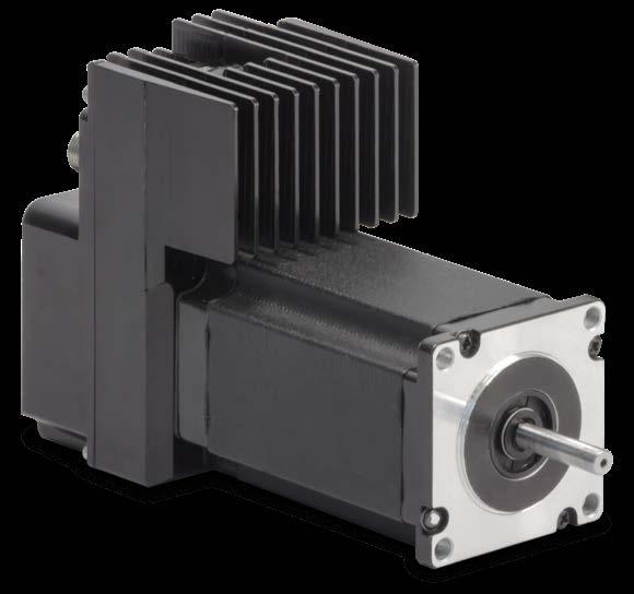


1 EtherNet/IP USER'S GUIDE ACS Servo ACS Stepper ACSI Servo _10_EtherNetIP LINEAR SOLUTIONS MADE EASY
2 Tolomatic reserves the right to change the design or operation of the equipment described herein and any associated motion products without notice. Information in this document is subject to change without notice. Copyright 2018 Tolomatic, Inc. All rights Reserved. All brand and product names are trademarks of their respective owners. Information in this document is believed to be accurate at time of publication
3 Contents EtherNet/IP Overview Introduction Network Definitions Layer Structure Supported Features of EtherNet/IP Recommended Implementation and Alerts Case #1: PLC sending CIP I/O messages through switch with star topology Case #2: PLC sending CIP I/O and CIP Motion messages through switch with star topology Case #2.5: PLC sending CIP I/O and CIP Motion messages through switch with star topology What is VLAN? Case #3: PLC sending CIP I/O messages to daisy chain of ACS drives and other EtherNet/IP devices Case #4: PLC sending CIP I/O and CIP Motion messages to daisy chain of ACS drives and other EtherNet/IP devices Case #5: PLC sending CIP Motion messages in Rockwell device level ring (DLR) with ACS drive connected with a 1783-ETAP device Case #6: AB PLC with CIP I/O and CIP Motion devices through switch Case #7: AB PLC with CIP I/O and CIP Motion/Sync devices in Device Level Ring (DLR) network topology References ACS EtherNet/IP Requirements Ethernet Cabling Cabling Tolomatic Motion Interface (TMI) Requirement Add-On Instructions EtherNet/IP & I/O Connections Data Types Input Assembly Output Assembly Explicit Messaging Identity Object (01 HEX - 1 Instance) Assembly Object DLR Object (47 HEX - 1 Instance) TCP/IP Object (F5 HEX - 1 Instance) EtherNet/IP Link Object (F6 HEX - 1 Instance) QoS Object (48 HEX - 1 Instance) Appendix A: Trouble Shooting Appendix B: ODVA Declaration of Conformity
4 List of Figures Figure 1-1: EtherNet/IP Network Example... 6 Figure 1-2: ACS & ACSI Drive as an Adapter Device... 7 Figure 1-3: EtherNet/IP Layer Structure with the ACS Drive as the User Device Profile... 8 CASE #1: PLC with only CIP I/O messages switch star topology of ACS drives and other EtherNet/IP devices... 9 CASE #2: PLC with CIP I/O and CIP Motion messages switch star topology of ACS drives and other EtherNet/IP devices... 9 CASE #2.5: PLC sending CIP I/O and CIP Motion messages through switch with star topology Figure 1-4: VLAN Diagram CASE #3: PLC with only CIP I/O messages daisy chain topology of ACS drives and other EtherNet/IP devices CASE #4: PLC with CIP I/O and CIP Motion messages daisy chain topology of ACS drives and other EtherNet/IP devices CASE #5: PLC sending CIP Motion messages in Rockwell device level ring (DLR) with ACS drive connected with a 1783-ETAP device CASE #6: AB PLC with CIP I/O and CIP Motion devices through switch CASE #7: PLC sending CIP Motion messages in Rockwell device level ring (DLR) with ACSI motor/drive/controller Figure 3-1 EtherNet/IP I/O Assembly
5 List of Tables Table 2-1: Cable Wire Type Versus Cable Length Table 3-1: Data Types Table 3-2: ACS EtherNet/IP Input Assembly Table 3-3: ACS Drive Status Table 3-4: ACS Drive Faults Table 3-5: ACS EtherNet/IP Output Assembly Table 3-6: ACS EtherNet/IP Full Output Assembly Table 3-7: ACS EtherNet/IP Move Values and Descriptions Table 4-1: Message Objects Table 4-4: Assembly Object (04 HEX. 6 Instances) Table 4-5: Assembly Objects Common Services Table 4-6: DLR Object (47 HEX - 1 Instance) Table 4-7: TCP/IP Object (0xF5 HEX - 1 Instance) Table 4-8: TCP/IP Object Common Services Table 4-9: Ethernet Link Object (0xF6 HEX - 1 Instance) Table 4-10: TCP/IP Object Common Services Table 4-11: QoS Object (48 HEX - 1 Instance) Table 4-12: QoS Object's common services Table 4-13: EtherNet/IP LED Indicators
6 1.1 Introduction EtherNet/IP Overview1 EtherNet/IP has been instrumental in realizing high performance and advanced automating manufacturing applications. Common Industrial Protocol (CIP) has enabled the enterprise for: Interoperability between legacy, multi-vendor internet technologies Near real-time network performance (including low latency, low jitter, and minimal packet loss) Security Reliability Manageability and ease-of-use features Ability to add innovative technologies such as mobile technologies EtherNet/IP provides comprehensive messaging and services for control, safety, synchronization, motion, configuration and information that creates unified communication across manufacturing enterprise. NOTE: This document is intended to provide information on the EtherNet/IP protocol only. Please reference the ACS Hardware/Installation Guide for all electrical and hardware installation procedures, specifications, and safety instructions when operating the ACS Drive. Tolomatic's implementation of EtherNet/IP connectivity conforms to the Open Systems Interconnection (OSI) model which defines the framework of implementing network protocols in seven layers. For more information regarding EtherNet/IP and CIP functionality and conformation standards as regulated by the ODVA, visit their website at The ACS drive is ODVA certified. 1.2 Network A typical EtherNet/IP network forms several point-to-point connections. A typical network in a factory would comprise of variety of complex devices such as HMIs, PLCs, motion controllers, bar code scanners to simple devices such as I/O. This configuration is represented in Figure 1-1. Controller CIP Network Sensor Other Devices Motor Starter Pushbutton Cluster Device Configuration Input/Output Devices Figure 1-1: EtherNet/IP Network Example 1.3 Definitions Drive Motor Controller The following definitions provide a general context for terms used in this guide in the EtherNet/IP implementation: Device: A device is considered any product that supports the EtherNet/IP encapsulation of CIP. Bar Code Scanner EtherNet/IP TM Programmer's Guide: 6 ACS Drive/Controller
7 1 : OVERVIEW Connection: A connection is a logic link between two devices that may share more than one connection. Scanner: A master or controlling device that initiates a request or connection. Adapter: A device that receives a connection request or an individual service request. Multiple adapters can be connected to one scanner on a network. The ACS drive is an adapter device (see Figure 1-2). Assembly: A collection of pre-defined data that resides in an adapter. Each datapoint is identified by its own unique instance number, size and type. There are three types of assemblies: producing (data to be sent); consuming (data to be received); and configuration (how the data is to be consumed and interpreted). (SCANNER) PLC (ADAPTER) ACS (SCANNER) HMI (ADAPTER) ACSI Figure 1-2: ACS & ACSI Drive as an Adapter Device. Explicit Messaging Connection: A connection used for individual request/ response transactions that are handled in the EtherNet/IP protocol via TCP. For example, an explicit connection request from a scanner device results in a response from the adapter device indicating a successful or failed request. If data payload was part of the request, this information would also be included. Requests from a scanner device is called a service request and these requests are identified by one-byte service codes inside the request pocket. CIP specifications define the meaning of the majority of these service codes however, codes 0x4B through 0x63 have meanings specific to the destination object of the service request. Service request destinations are defined by a portion of the request packet, or path that is either an object description or an ASCII character string. The adapter device receiving a service request distinguishes between an object description path ASCII character string path by the path's header bytes. Class (type of object reference), instance (object of the type), and the attribute numbers inside the path identify a request to an object. For example, a mixed carton of oatmeal contains 24 packages (objects) and are considered instances 1 through 23. Each object can have multiple attributes. In this example, the carton contains 6 different flavors or attributes 1 through 6. An example service request from a scanner would be to ask for the flavor of package or object number 12. Explicit message commands or data requests can also be sent from the scanner to individual target nodes via connected or unconnected messages. A connected message establishes a formal CIP connection between devices that allows each device to detect and report either established or failed connections. Unconnected messages are managed by the internal stack's Unconnected Message Manager (UCMM) and does not establish a periodic explicit connection. Implicit or I/O Connection: A connection that establishes a periodic exchange of data between a scanner and adapter. A repetition packet interval or RPI (normally expressed in milliseconds) is established by the scanner device in both directions. An I/O connection request also establishes the size of each assembly and the instance numbers of the assembly types (producing, consuming and configuration). To allow the adapter to interpret subsequent data exchange, an I/O connection may also contain data destined for the adapter's configuration assembly. In EtherNet/IP the I/O connection itself is established via TCP but the subsequent exchange of data uses UDP. An I/O connection also determines how the adapter device should send its data, either point-to-point (addressed to the scanner only) or multicast (address group that includes the scanner), and allows other devices on the network to receive data from the adapter. NOTE: If the data is sent via multicast, the adapter device itself must 7

8 1 : OVERVIEW support multicast or the connection will fail. Both, explicit service requests and implicit I/O connections allow scanner access to parameters, however the process differs. Typically, the scanner device utilizes HMI or PLC software such as Allen Bradley's ControlLogix. PLC's normally will make both explicit and I/O connections. 1.4 Layer Structure Figure 1-3 below shows the seven layers of protocol implementation. Tolomatic's ACS Drive user device profile resides on the seventh layer. Figure 1-3: EtherNet/IP Layer Structure with the ACS Drive as the User Device Profile 1.5 Supported Features of EtherNet/IP ACS Servo, Stepper and Integrated drives support EtherNet/IP using CIP I/O messaging (implicit as well as explicit messaging). This allows Rockwell Automation / Allen Bradley ControlLogix and CompactLogix PLCs (as well as other manufacturers PLCs or controllers) to command ACS drives over EtherNet/IP with CIP I/O messages. The ACS drives do not directly support CIP Motion or CIP Sync (both these are trademarked by ODVA) messages over EtherNet/IP. The ACS Servo, Stepper, & Integrated drives support QoS (Quality of Service) and have an integrated managed switch to support star and straight line daisy chain topology from managed or unmanaged switches. Additionally the ACS Integrated drive (ACSI) supports Device Level Ring (DLR) EtherNet/IP feature, ring topology, and can be easily integrated into CIP Motion / CIP Sync networks. 1.6 Recommended Implementation and Alerts With Ethernet networks, there are many different ways to connect devices, many different ways to configure devices, and many different types of messages/ protocols. Due to the infinite network configurations, it is not possible to document all scenarios and cases. This section describes some more common ways that the ACS drive family can be deployed in an EtherNet/IP network along with recommendations and alerts to achieve optimal performance. 8

9 1 : OVERVIEW Case #1: PLC sending CIP I/O messages through switch with star topology CASE #1: PLC with only CIP I/O messages > switch > star topology of ACS drives and other EtherNet/IP devices RECOMMENDATION: Utilize star topology for best network performance and response time / quality from ACS Servo & Stepper drive Case #2: PLC sending CIP I/O and CIP Motion messages through switch with star topology CASE #2: PLC with CIP I/O and CIP Motion messages > switch > star topology of ACS drives and other EtherNet/IP devices RECOMMENDATION: For the ACS Servo & ACS Stepper If CIP I/O and/or CIP Motion messages are present on the same network, it is recommended to utilize a VLAN to logically separate CIP I/O EtherNet/IPTM (see Case #2.5). This recommendation is not necessary for the ACS Integrated drive (ACSI) RECOMMENDATION: If CIP I/O and/or CIP Motion messages are present on the same network, it is recommended to configure PLC to send CIP I/O messages as Unicast and CIP Motion messages as Multicast. 9


10 1 : OVERVIEW This recommendation is not necessary for the ACS Integrated drive (ACSI) Case #2.5: PLC sending CIP I/O and CIP Motion messages through switch with star topology CASE #2.5: PLC sending CIP I/O and CIP Motion messages through switch with star topology RECOMMENDATION: It is recommended to use a VLan as best practice in this case to avoid unpredictable network behavior. See Case #2 for more information. This recommendation is not necessary for the ACS Integrated drive (ACSI). RECOMMENDATION: If CIP I/O and/or CIP Motion message are present on same network, it is recommended to configure PLC to send CIP I/O message as Unicast and CIP Motion messages as Multicast. This recommendation is not necessary for the ACS Integrated drive (ACSI). 10


11 1 : OVERVIEW What is VLAN? Virtual Local Area Networks are used to divide a physical network into several broadcast domains, separating hosts that shouldn't access each other. Figure 1-4: VLAN Diagram Case #3: PLC sending CIP I/O messages to daisy chain of ACS drives and other EtherNet/IP devices CASE #3: PLC with only CIP I/O messages > daisy chain topology of ACS drives and other EtherNet/IP devices RECOMMENDATION: In daisy chain, the ACS drive cannot guarantee recovered communication if a network cable is broken or unplugged. It is recommended to design your system such that all drives can be power cycled at the same time. This recommendation is not necessary for the ACS Integrated drive (ACSI). RECOMMENDATION: Daisy chaining a large number of ACS drives can create additional network latencies. The number of ACS drives that can be daisy chained in a particular network is highly dependent on the polling rate of the PLC, additional devices, other network traffic and many other variables. It is recommended to test network speed and minimize number of ACS drives in each daisy chain to ensure optimal performance. This recommendation is not necessary for the ACS Integrated drive (ACSI). 11

 is not affected by network traffic and can be deployed on the network in such a manner. 1.6.")
12 1 : OVERVIEW Case #4: PLC sending CIP I/O and CIP Motion messages to daisy chain of ACS drives and other EtherNet/IP devices CASE #4: PLC with CIP I/O and CIP Motion messages > daisy chain topology of ACS drives and other EtherNet/IP devices NOT SUPPORTED: The ACS Servo and Stepper drives are not able to reliably pass CIP Motion and CIP Sync messages in high network traffic instances. The ACS Integrated (ACSI) is not affected by network traffic and can be deployed on the network in such a manner Case #5: PLC sending CIP Motion messages in Rockwell device level ring (DLR) with ACS drive connected with a 1783-ETAP device CASE #5: PLC sending CIP Motion messages in Rockwell device level ring (DLR) with ACS drive connected with a ETAP device RECOMMENDATION: An ETAP device is required to be used to attach the ACS Servo & Stepper drive and other CIP I/O devises in order to avoid unpredictable network behavior. A suggested ETAP device is the Rockwell 1783-ETAP device. See below for further information on the 1783-ETAP device. 12
13 1 : OVERVIEW This device is not required for the ACS Integrated drive (ACSI) as it supports Device Level Ring (DLR) implementation. RECOMMENDATION: If CIP I/O and/or CIP Motion message are present on same network, it is recommended to configure PLC to send CIP I/O message as Unicast and CIP Motion messages as Multicast. This recommendation is not necessary for the ACS Integrated drive (ACSI). ALERT: The ACS Servo & Stepper drive by itself does not support DLR feature of EtherNet/IP. A 1783-ETAP device is required in order to not interrupt the CIP Motion messages in Rockwell DLR topology. The ACS drive can be daisy chained off of the 1783-ETAP device as well as other CIP I/O devices. When the ACS and other CIP I/O devices are in this configuration, even with the 1783-ETAP device, they will not provide DLR feedback when the chain is broken. They will act as if they are in a daisy chain configuration. This device is not required for the ACS Integrated drive (ACSI) as it supports Device Level Ring (DLR) implementation Case #6: AB PLC with CIP I/O and CIP Motion devices through switch CASE #6: AB PLC with CIP I/O and CIP Motion devices through switch RECOMMENDATION: It is recommended to use a VLan as best practice in this case to avoid unpredictable network behavior. See Case #2 for more information. This recommendation is not necessary for the ACS Integrated drive (ACSI). RECOMMENDATION: If CIP I/O and/or CIP Motion message are present on same network, it is recommended to configure PLC to send CIP I/O message as Unicast and CIP Motion messages as Multicast. This recommendation is not necessary for the ACS Integrated drive (ACSI). 13
 network topology CASE #7: PLC sending CIP Motion messages in Rockwell device level ring (DLR) with ACSI")

14 1 : OVERVIEW Case #7: AB PLC with CIP I/O and CIP Motion/Sync devices in Device Level Ring (DLR) network topology CASE #7: PLC sending CIP Motion messages in Rockwell device level ring (DLR) with ACSI motor/drive/controller RECOMMENDATION: The ACS Integrated servo drive (ACSI) fully supports Device Level Ring (DLR) over EtherNet/IP. This is the recommended network topology for applications requiring the highest level of redundancy. NOT SUPPORTED: The ACS Servo & Stepper drive do not support Device Level Ring (DLR) over EtherNet/ IP without the use of a 1783-ETAP device as an entry point to the network. 1.7 References {1} The CIP Network Library Volume 1: Common Industrial Protocol, Edition 3.10, April 2011 {2} The CIP Network Library Volume 2: EtherNet/IP Adaptation of CIP, Edition 1.11, April
15 2.1 Ethernet Cabling ACS EtherNet/IP Requirements2 The ACS Stepper and Servo drive use standard Rj45 connectors and network CAT5 style cables. ACSI uses circular M12 D-code 4 pin connectors. Please refer to the hardware manuals for further cable information (Hardware and Installation Guide; ACS Stepper: ; ACS Servo: ; ACSI: ) See appendix for network cable type and length specification. 2.2 Cabling The selection of cable has a profound impact on network performance and reliability. Selecting the correct cable requires an understanding of the environment where the cable is installed. Due to high data rate and reliability considerations, at the minimum, Cat5e cables should be used with the ACS drive. If the cables are made on site, they must be tested to meet performance criteria set according to TIA/EIA- 568-B standard. This cable definition is the general cable requirements for copper and fiber cabling installations. EtherNet/IP specifications limit the channel to 100 meters or up to 90 meters horizontal wiring with two 4-meter patch cords. Some applications will require longer patch cords. In these applications the total length of horizontal wiring must be adjusted to compensate for the added loss of each connector pair and additional patch cord length beyond 10m. (102-H) C = (1 + D) (1) Where: C is the maximum combined length (m) of the work area cable, equipment cable, and patch cord. H is the length (m) of the horizontal cable (H + C <= 100 m). D is a de-rating factor for the patch cord type (0.2 for 24 AWG UTP/24 AWG ScTP and 0.5 for 26 AWG ScTP). The derating factors are based on COMMERCIAL cables. Other constructions, such as high flex, may have different performance. Consult the manufacturer for information. W is the maximum length (m) of the work area cable. T is the total length of horizontal, patch and equipment cords. The maximum stranded cable length is limited to 85mm for the channel with the standard 20% derating for standard stranded cables. PATCH CABLE GAUGE WIRE TYPE VERSUS LENGTH D H W C T PATCH DERATING HORIZONTAL LENGTH (H+C 100M) PATCH LENGTH TOTAL LENGTH PATCH AND EQUIPMENT TOTAL LENGTH OF PATCH, EQUIPMENT AND HORIZONTAL # # # # # # # # Table 2-1: Cable Wire Type Versus Cable Length Please refer to Section of the ODVA EtherNet/IP Standard v for additional information. EtherNet/IP TM Programmer's Guide: 15 ACS Drive/Controller
16 2 : ACS EtherNet/IP CONNECTIONS 2.3 Tolomatic Motion Interface (TMI) Requirement The TMI is used to configure the ACS Drive including setting up the Ethernet port. See TMI User Guide # for complete information on configuration using TMI. 2.4 Add-On Instructions The Add-On Instructions Zip file contains an EDS file which can be used to configure the ACS drive. Tech Note, ACS(I) & Allen Bradley RS Logix 5000 EtherNet/IP Setup # describes this process, available at ( ) is the part number for the ACSI motor/drive/controller EDS file. 16

17 EtherNet/IP & I/O Connections 3 The ACS drive will only allow two I/O connections. The ACS drive responds to connection and service requests from a scanner and no commands or parameters from the drive are required to allow these connections. However, certain commands and parameters from the ACS drive allow a user or program to monitor the status and descriptions of the connections. An implicit or I/O connection sets up the periodic exchange of data between the ACS drive and the data tags in scanner memory. These data tags are collectively referred to as assemblies. Setting up these assemblies is normally part of the PLC configuration process and separate from the PLC ladder programming. An I/O messaging service request may result from a software driver implementation (such as EIP Scan from Pyramid Systems), or may be part of a message box inside a ladder rung of a PLC program. Service requests always contain a code which specifies what is being requested, and a path which specifies destination object of request. The paths of some of these service codes supported in the ACS drive may take the form of an ASCII character string or tag. Other paths will require specification of class, instance and attribute. Input and output directions are from the perspective of scanner device. Input assemblies are consumed by scanner devices and produced by adapter devices. Output assemblies are produced by a scanner device and consumed by an adapter device. Refer to Figure 3-1. Output assemblies are commonly used for controlling the enable/disable state of the drive and for supplying the velocity or position reference. Input assemblies are commonly used to monitor the drive status and run-time quantities such as current position and faults. Figure 3-1 EtherNet/IP I/O Assembly 3.1 Data Types Data Types used in this Object Model are described in Table 3-1 below. DATA TYPE USINT UINT UDINT SHORT STRINGnn WORD DWORD REAL Table 3-1: Data Types DESCRIPTION Unsigned Short Integer (8-bit) Unsigned Integer (16-bit) Unsigned Double Integer (32-bit) Character String (1st byte is length; up to nn characters) Bit String (16-bits) Bit String (32-bits) IEEE 32-bit Single Precision Floating Point EtherNet/IP TM Programmer's Guide: 17 ACS Drive/Controller
18 3.2 Input Assembly 3: EtherNet/IP & I/O CONNECTIONS INSTANCE ATTRIBUTE ID BYTES TYPE VALUE Input (T->0) REAL Current Position (mm) Instance DWORD Drive Status (32 bitmap status) 8-11 DWORD Drive Faults (32 bitmap faults) DWORD Digital Input (8 bits used out of 32) DWORD Digital Output (4 bits used out of 32) REAL Analog Input REAL Analog Output Table 3-2: ACS EtherNet/IP Input Assembly ACS DRIVE STATUS BIT DESCRIPTION 0 Drive Enable: 0 = Not Enabled; 1 = Enabled 1 Drive Homed: 0 = Not Homed; 1 = Homed 2 Drive In Motion: 0 = Motion Complete; 1 = In Motion 3 Software Stop: 0 = OFF; 1 = ON 4 (internal use) 5 (internal use) 6 (internal use) 7 (internal use) 8 (internal use) 9 (internal use) (internal use) 20 Brake Not Active (1 - Not Active; 0 - Active) **Reserved 31 Drive Control: 0 = OFF (I/O, CTROFF), 1 = ON (Host, CTRON) Table 3-3: ACS Drive Status BIT ACS DRIVE FAULTS DESCRIPTION 0 Positive Limit 1 Negative Limit 2 Software Stop 3 Position Error 4 Feedback Error 5 Overcurrent 6 Motor Overtemperature 7 Drive Overtemperature 8 Drive OverVolatage 9 Drive UnderVoltage 10 Flash Error 11 I2T Limit 12 Short Circuit 13 Watchdog Reset (internal use) Table 3-4: ACS Drive Faults ACS Servo Drive / ACSI 18
19 3.3 Output Assembly 3: EtherNet/IP & I/O CONNECTIONS INSTANCE ATTRIBUTE ID BYTES TYPE VALUE Input (0->T) Instance 112 Table 3-5: ACS EtherNet/IP Output Assembly 3 0 USINT DRIVE COMMAND VALUE COMMAND 0 Disable / Clear 1 Enable / Clear 3 Start Motion 5 Home 8 Software Stop (E Stop) 9 Software Stop (E Stop) 17 Stop Motion (Using Profile Decel 21 Home Here 1 USINT Move Select (0-16) 2-3 NA Reserved INSTANCE ATTRIBUTE ID BYTES TYPE VALUE Output (O->T) 3 0 USINT DRIVE COMMAND Instance 113 VALUE COMMAND 0 Disable / Clear 1 Enable / Clear 3 Start Motion 5 Home 8 Software Stop (E Stop) 9 Software Stop (E Stop) 17 Stop Motion (Using Profile Decel 21 Home Here 1 USINT Move Select (0-16) 2-3 NA Reserved 3-7 REAL Target 0 Position (mm)* 8-11 REAL Target 0 Velocity (mm/s) REAL Target 0 Acceleration (mm/s 2 ) REAL Target 0 Deceleration (mm/s 2 ) REAL Target 0 Force (% of max) DWORD Target 0 Motion Type (see table 3-7) DWORD Digital Output (4 bits used out of 32) Table 3-6: ACS EtherNet/IP Full Output Assembly *Units can be configured in Revs or Degrees with a Rotary actuator setup. 19
20 3: EtherNet/IP & I/O CONNECTIONS NAME VALUE DESCRIPTION Absolute 0 Moves to location at profile defined for Target O Inc. Positive 1 Moves in the positive direction the distance specified by Target O Position at the defined motion profile Inc. Negative 2 Moves in the negative direction the distance specified by Target O Position at the defined motion profile Home 5 Executes a home move using the defined homing profile No Action 6 Does not execute motion Inc. Positive Rotary 11 Inc. Negative Rotary 12 Force 9 Press to Force (% current) (See TMI manual for complete description) Velocity Forward 13 Velocity Reverse 14 Moves in the positive direction the distance specified by Target O Position at the defined motion profile. If position is commanded past the maximum distance, current position is reset Moves in the negative direction the distance specified by Target O Position at the defined motion profile. If position is commanded past the maximum distance, current position is reset Starts a velocity move in the positive direction at profile velocity and acceleration *Stepper drives require the motor to be stationary when this command is issued Starts a velocity move in the negative direction at profile velocity and acceleration *Stepper drives require the motor to be stationary when this command is issued Table 3-7: ACS EtherNet/IP Move Values and Descriptions 20
21 Explicit Messaging4 One of the explicit message objects is allocated as part of the predefined slave/adapter connection set as defined in the EtherNet/IP specification. The other may be allocated using the Unconnected Message Manager (UCMM) protocol. These objects can be used to access ACS Parameters. OBJECT ID OBJECT NAME PURPOSE 1 Vendor Identity Identifies the drive as ACS Drive & Controller 4 Assembly ACS Drive currently supports two (2) Output assembly objects and one (1) Input assembly object as specified by EtherNet/IP standard 71 DLR Device Level Ring information (ACSI Only) 72 QoS Quality of Service (ACSI Only) 245 TCP ACS Drive TCP/IP Interface Object provides information about TCP/IP network interface such as IP Address, Network Mask, Gateway, Host Name 246 Ethernet Link ACS Drive Ethernet Link Object provides information about Speed and Duplex connection Table 4-1: Message Objects 4.1 Identity Object (01 HEX - 1 Instance) The following tables contain the attribute, status, and common services information for the Identity Object. INSTANCE ATTRIBUTE ID NAME CIP DATA TYPE DATA VALUE Class (Instance 0) 1 Revision UINT 1 Instance 1 1 Vendor number UINT Device type UINT 43 3 Product code number UINT 9046: ACS Stepper & Servo 9058: ACSI Motor/Drive/Controller 4 Product major revision USINT 2: ACS 1: ACSI Product minor revision USINT 37: ACS 1: ACSI 5 Status WORD NA 6 Serial number UDINT Unique 32 bit value Table 4-2: Identity Object (01 HEX - 1 Instance) 7 Product name SHORT STRING32 ACS Drive & Controller: ACS ACS Drive & Controller: ACSI EtherNet/IP TM Programmer's Guide: 21 ACS Drive/Controller
22 4: EXPLICIT MESSAGING Identity Object Common Services SERVICE CODE IMPLEMENTED FOR SERVICE NAME CLASS LEVEL INSTANCE LEVEL 01 HEX No Yes Get_Attribute_All 05 HEX No Yes Reset 0E HEX Yes Yes Get_Attribute_Single 10 HEX No Yes Set_Attribute_Single Table 4-3: Identity Objects Common Services 4.2 Assembly Object The following tables contain the attribute, instance, data mapping, and common services information for the Assembly Object. INSTANCE ATTRIBUTE ID NAME CIP DATA TYPE DATA VALUE Class (Instance 0) 1 Revision UINT 2 2 Max instance UINT 129 Input 3 (T->0) Refer to Table 3-2 (Instance 100) Output 3 (0->T) Refer to Table 3-5 (Instance 112) Output 3 (0->T) (Instance 113) Refer to Table (0xFE) 4 Input only heartbeat 1 Heartbeat (0xFF) 5 Listen only Heartbeat 0 heartbeat (0xFD) 6 Output Only heartbeat 3 Heartbeat 0 1 This instance allows clients (PLCs) to monitor input data without providing output data. 2 This instance allows clients (PLCs) to monitor input data without providing output data. To use this connection type, an owning connection must exist from a second client and the configuration of the connection must match exactly. 3 This instance allows output data without providing input data. Table 4-4: Assembly Object (04 HEX. 6 Instances) Assembly Object Common Services SERVICE CODE IMPLEMENTED FOR SERVICE NAME CLASS LEVEL INSTANCE LEVEL E HEX Yes Yes Get_Attribute_Single 10 HEX No Yes Set_Attribute_Single Table 4-5: Assembly Objects Common Services 22
23 4: EXPLICIT MESSAGING 4.3 DLR Object (47 HEX - 1 Instance) Please refer to Volume 2: EtherNet/IP Adaptation of CIP v. 1.11, for exact format and interpretation of attributes. INSTANCE ATTRIBUTE ID NAME DATA TYPE Class (Instance 0) 1 Revision UINT Instance 1 1 Network Topology USINT 2 Network Status USINT 10 Active Supervisory Address STRUCT 12 Capability Flags DWORD Table 4-6: DLR Object (47 HEX - 1 Instance) 4.4 TCP/IP Object (F5 HEX - 1 Instance) Please refer to Volume 2: EtherNet/IP Adaptation of CIP v. 1.11, for exact format and interpretation of attributes. INSTANCE ATTRIBUTE ID NAME DATA TYPE Class (Instance 0) 1 Revision UINT Instance 1 1 Status DWORD 2 Configuration capability DWORD 3 Configuration control DWORD 4 Physical Link Object Structure of Path size Path 5 Interface configuration Structure of IP Address Network MasK Gateway Address Name Server Name Server 2 Domain Name Size Domain Name 6 Host name Structure of Host Name Size Host Name Table 4-7: TCP/IP Object (0xF5 HEX - 1 Instance) UINT Array of Word UDINT UDINT UDINT UDINT UDINT UINT STRING UINT STRING 8 TTL Value (ACSI) UINT 9 MCAST Config (ACSI) STRUCT, USINT, USINT, L3INT VDDA 10 Select ACD (ACSI) BOUL 11 Last Conflict Detected (ACSI) STRUCT 12 EtherNet/IP Quick Consent BOUL 23
24 4: EXPLICIT MESSAGING TCP/IP Object Common Services SERVICE CODE IMPLEMENTED FOR SERVICE NAME CLASS LEVEL INSTANCE LEVEL E HEX Yes Yes Get_Attribute_Single 10 HEX No Yes Set_Attribute_Single Table 4-8: TCP/IP Object Common Services 4.5 EtherNet/IP Link Object (F6 HEX - 1 Instance) Please refer to Volume 2: EtherNet/IP Adaptation of CIP v. 1.11, Section for exact format and interpretation of attributes. INSTANCE ATTRIBUTE ID NAME DATA TYPE Class (Instance 0) 1 Revision UINT Instance 1 1 Interface speed UDINT 2 Interface flags DWORD 3 Physical address USINT Array (6) Table 4-9: Ethernet Link Object (0xF6 HEX - 1 Instance) Ethernet Link Object Common Services SERVICE CODE IMPLEMENTED FOR SERVICE NAME CLASS LEVEL INSTANCE LEVEL E HEX Yes Yes Get_Attribute_Single 10 HEX No Yes Set_Attribute_Single Table 4-10: TCP/IP Object Common Services 4.6 QoS Object (48 HEX - 1 Instance) The following tables contain the attribute and common services information for the QoS Object. INSTANCE ATTRIBUTE ID QoS Object (F6 HEX - 1 Instance) NAME DATA DATA TYPE VALUE ACCESS RULE Class 1 Revision UINT 1 Get (Instance 0) Instance Q Tag Enable UINT NA Not Supported 2 DSCP PTP Event UINT NA Not Supported 3 DSCP PTP General UINT NA Not Supported 4 DSCP Urgent UINT 55 Get / Set 5 DSCP Scheduled UINT 47 Get / Set 6 DSCP High UINT 43 Get / Set 7 DSCP Low UINT 31 Get / Set 8 DSCP Explicit UINT 27 Get / Set *For more details on these attributes, see Volume 2: EtherNet/IP Adaptation of CIP, Section from ODVA. Table 4-11: QoS Object (48 HEX - 1 Instance) 24
25 4: EXPLICIT MESSAGING QoS Object's common services IMPLEMENTED FOR SERVICE CODE CLASS LEVEL INSTANCE LEVEL SERVICE NAME 01 HEX NO YES Get_Attribute_All 0E HEX YES YES Get_Attribute_All 10 HEX NO YES Get_Attribute_All Table 4-12: QoS Object's common services EtherNet/IP LED Indicators MOD SYSTEM TEST NET SYSTEM STATUS Off No Power Off Not Powered / No IP Address Steady Green Module Operational Steady Green Connected Flashing Green Standby Flashing Green No Connections Steady Red Major Fault Steady Red Duplicate IP Flashing Red Minor Fault Flashing Red Connection Timeout Flashing Red/Green Self-Test Flashing Red/Green Self-Test Table 4-13: EtherNet/IP LED Indicators 25
26 Appendix A: Troubleshooting Troubleshooting For every module connected to the EtherNet/IP system verify that: 1. Link state: MUST be UP (connected to a powered switch) 2. Duplex: MUST be Full duplex 3. Auto/forced: MUST be able to Autonegotiate the speed 4. Speed: MUST be 100Mbps 5. Errors: MUST be 0 for BOTH, In errors and out errors 6. CIP connection timeouts: should be 0 7. CIP connections: MUST be<= 80-90% of the module s capacity 8. TCP connections: MUST be<= 80-90% of the module s capacity 9. CPU usage%: MUST be<= 80-90% 10. Missed I/O packets: MUST be NO missed packets i.e. missed I/O packets should be set to HMI packets/sec: MUST be <= 80-90% of the module s capacity 12. I/O packets/sec: MUST be <= 80-90% of the module s capacity SYMPTOM/TROUBLE No Ethernet Communication 1. Check Ethernet Cable. POSSIBLE CAUSE/RESOLUTION 2. Verify Ethernet Cable is plugged in securely. 3. Incorrect combination of IP Address, Subnet Mask, Gateway. Check with your network administrator to determine correct combination. 4. Try different Ethernet port on the drive. 5. Verify RPI is not faster than 20 ms. Larger RPI required for larger # drives. No EtherNet/IP connectivity 1. Check your assembly configuration. 2. Check if Ethernet communication can be established with the drive using PING utility. 3. Check if Digital Outputs can be set/reset using EtherNet/IP O->T assembly. 4. Advanced Troubleshooting Tip: Check Ethernet packets received and sent to the PLC from and to the drive. EtherNet/IP TM Programmer's Guide: 26 ACS Drive/Controller
27 A P P E N D I X A: TROUBLESHOOTING SYMPTOM/TROUBLE Motion cannot be executed over EtherNet/IP POSSIBLE CAUSE/RESOLUTION 1. Check if Drive Status, Drive Faults, Digital Inputs and Outputs can be queried over EtherNet/IP. If drive is not sending them, then troubleshoot Ethernet communication. 2. Check if drive is configured with EtherNet/IP communication mode using Tolomatic Motion Interface Software. 3. Check if Digital Outputs can be set/reset using EtherNet/IP O->T assembly. If the Digital Outputs of the drive cannot be set or reset using EtherNet/IP O->T assembly then troubleshoot the Ethernet communication. 4. Advanced Troubleshooting Tip: Try different EtherNet/IP scanner to interface with Tolomatic ACS Drive. The I/O tree in RSLogix5000 has a yellow triangle on a ACS drive. Note following about the ACS drive: 1. Only a single device is being lost? Example: Only a single device, a (ACS Stepper drive & Controller), has a yellow triangle 2. Was it ever operating correctly or did this start recently? 3. How often does it happen? (constantly, once per hour, once per week?) 4. For how long does the anomaly last? (3 seconds, forever?) 5. How do you recover? (cycle power to device?, recovers by itself?) 6. What additional steps, if any, did you already take to troubleshoot? E.g. hardware changes 7. Contact Tolomatic support 27
28 Appendix B: ODVA Declaration of Conformity EtherNet/IP TM Programmer's Guide: 28 ACS Drive/Controller
29 APPENDIX B: ODVA DECLARATION OF CONFORMITY 29
 478-8000 Fax: (763) 478-8080 Toll-Free: 1-800-328-2174 sales@tolomatic.")

30 _10_EtherNetIP Visit for the most up-to-date technical information 2018 TOLOMATIC USA 3800 County Road 116 Hamel, MN 55340, USA Phone: (763) Fax: (763) Toll-Free: EUROPE Tolomatic Europe GmbH Zeilweg Frankfurt am Main Germany Phone: All brand and product names are trademarks or registered trademarks of their respective owners. Information in this document is believed accurate at time of printing. However, Tolomatic assumes no responsibility for its use or for any errors that may appear in Visit for the most up-to-date technical information 30 8 CHINA Tolomatic Automation Products (Suzhou) Co. Ltd. (ServoWeld inquiries only) No. 60 Chuangye Street, Building 2 Huqiu District, SND Suzhou Jiangsu P.R. China Phone: +86 (512) Fax: +86 (512) ServoWeldChina@tolomatic.com this document. Tolomatic reserves the right to change the design or operation of the equipment described herein and any associated motion products without notice. Information in this document is subject to change without notice.
EtherNet/IP USER'S GUIDE ACS Servo ACS Stepper ACSI Servo
 EtherNet/IP USER'S GUIDE ACS Servo ACS Stepper ACSI Servo 3600-4168_13_EtherNetIP LINEAR SOLUTIONS MADE EASY Tolomatic reserves the right to change the design or operation of the equipment described herein
ACS Stepper _10_Modbus LINEAR SOLUTIONS MADE EASY
 MODBUS RTU & TCP PROGRAMMER S GUIDE ACSI ACS Stepper ACS Servo 3600-4169_10_Modbus LINEAR SOLUTIONS MADE EASY Tolomatic reserves the right to change the design or operation of the equipment described herein
PROFINET USER S GUIDE ACSI Servo
 PROFINET USER S GUIDE ACSI Servo 3600-4196_05 Tolomatic reserves the right to change the design or operation of the equipment described herein and any associated motion products without notice. Information
Technical Note. ACSI Motor/Drive/Controller & ACS Drive with Allen Bradley RSLogix 5000 EtherNet/IP Setup Guide. Contents
 ACSI Motor/Drive/Controller & ACS Drive with Allen Bradley RSLogix 5000 EtherNet/IP Setup Guide Contents 1. System Requirements... 2 2. Cabling... 2 3. Setting up the Tolomatic ACS Drive IP Address.. 2
ACSI Motor/Drive/Controller with Siemens TIA Portal PROFINET Setup Guide
 ACSI Motor/Drive/Controller with Siemens TIA Portal PROFINET Setup Guide 3600-4197_01 Tolomatic reserves the right to change the design or operation of the equipment described herein and any associated
ACSI ACTUATOR CONTROL SOLUTIONS
 ACSI ACTUATOR CONTROL SOLUTIONS INTEGRATED SERVO MOTOR / DRIVE / CONTROLLER LINEAR SOLUTIONS MADE EASY ACSI Motor/Drive/Controller WHAT IS THE ACSI? The ACSI is an extremely easy-to-use integrated servo
ACSI ACTUATOR CONTROL SOLUTIONS
 ACSI ACTUATOR CONTROL SOLUTIONS INTEGRATED SERVO MOTOR / DRIVE / CONTROLLER LINEAR SOLUTIONS MADE EASY ACSI Motor/Drive/Controller WHAT IS THE ACSI? The ACSI is an extremely easy-to-use integrated servo
DEFAULT IP ADDRESS
 REAL TIME AUTOMATION 2825 N. Mayfair Rd. Suite 111 Wauwatosa, WI 53222 (414) 453-5100 www.rtaautomation.com EtherNet/IP - DeviceNet Master Gateway MODBUS TCP - DeviceNet Master Gateway Copyright 2007 Real
GSE Scale Systems Ethernet IP Option
 AN SPX BRAND GSE Scale Systems Ethernet IP Option Option P/N 24660B-421C0 Revision 0.51 Apr 3, 2008 Page 1 of 27 TABLE OF CONTENTS 1. INTRODUCTION...5 1.1 Overview...5 1.2 Definiti ons...5 1.3 Reference
Tritex II EtherNet/IP - Option
 Tritex II EtherNet/IP - Option Tritex II Ethernet/IP Option.doc 10/15/13 REV B 952-368-3434 Tritex II EtherNet/IP Option.doc 2 10/15/13 Contents 1. General... 5 1.1. IP Address... 6 1.2. Network Classes...
Additional instructions Videographic recorder LINAX DR3000. EtherNet/IP Adapter
 Additional instructions Videographic recorder LINAX DR3000 EtherNet/IP Adapter Table of contents: 1 General information... 4 1.1 Registered trademarks... 4 1.2 Firmware history... 4 1.3 Scope of delivery...
EtherNet/IP - ODVA Conformance Test Results
 Sample Test Report EtherNet/IP - ODVA Conformance Test s Test Information Scheduled Test Date Composite Test Revision ODVA File Number Test Type CT13 Select from list Vendor Information Vendor Name DO
EtherNet /IP User Guide
 EtherNet /IP User Guide Trademark Notices Comtrol, DeviceMaster, and PortVision are registered trademarks of Comtrol Corporation. ControlLogix, PLC-5 and Rockwell Automation are registered trademarks of
FieldServer Driver - Ethernet FS EtherNet/IP
 Driver Version: 1.02 Document Revision: 2 Description FieldServer Driver - Ethernet FS-8704-14 EtherNet/IP The Ethernet IP driver allows the FieldServer to transfer data to and from devices over Ethernet
EtherNet/IP Programmer s Guide
 IPA Drive Controllers 88-032525-01 A EtherNet/IP Programmer s Guide Effective: February 2015 ENGINEERING YOUR SUCCESS. User Information Warning IPA Drive Controllers are used to control electrical and
EtherNet /IP User Guide
 EtherNet /IP User Guide Trademark Notices Comtrol, DeviceMaster, and PortVision are registered trademarks of Comtrol Corporation. ControlLogix, PLC-5 and Rockwell Automation are registered trademarks of
Chapter 5: Communications 5 1 SR55 Communications Overview 5 2
 Chapter 5 Table of Contents Chapter 5: Communications 5 1 SR55 Communications Overview 5 2 Modbus Serial Communications Overview 5 2 Modbus TCP Network Communications Overview 5 2 EtherNet/IP Network Communications
FieldServer Driver - Ethernet FS EtherNet/IP
 FieldServer Driver - Ethernet FS-8704-14 EtherNet/IP Description The EtherNet/IP driver allows the FieldServer to transfer data to and from an EtherNet/IP enabled device. This driver encapsulates the Control
ABSOLUTE ROTARY ENCODER W ITH ETHERNET/IP INTERFACE USER MANUAL
 ABSOLUTE ROTARY ENCODER W ITH ETHERNET/IP INTERFACE USER MANUAL 1. Introduction... 4 1.1 Control and Information Protocol (CIP)... 5 1.2 Object model... 5 2. Data Transmission... 6 2.1 Implicit Messaging
EtherNet/IP with Applied Motion Drives
 EtherNet/IP with Applied Motion Drives EtherNet/IP with Applied Motion Drives Jeff Kordik CTO Applied Motion Products, Inc. 1 92-5 Rev. B Applied Motion Products Contents Overview of EtherNet/IP...3 EtherNet/IP
ControlLogix EtherNet/IP Bridge Module
 Release Notes ControlLogix EtherNet/IP Bridge Module Catalog Number 1756-ENBT Topic Page Enhancements 2 Corrected Anomalies 7 Known Anomalies 11 Application Notes 12 Additional Resources 15 About This
Driver Manual. FS EtherNet/IP
 A Sierra Monitor Company Driver Manual (Supplement to the FieldServer Instruction Manual) FS-8704-14 EtherNet/IP APPLICABILITY & EFFECTIVITY Effective for all systems manufactured after July 2012 Driver
GUIDELINES FOR USING DEVICE LEVEL RING (DLR) WITH ETHERNET/IP. PUB00316R ODVA, Inc. Page 1 of 18
 WITH ETHERNET/IP. PUB00316R ODVA, Inc. Page 1 of 18") GUIDELINES FOR USING DEVICE LEVEL RING (DLR) WITH ETHERNET/IP PUB00316R2 2017-2018 ODVA, Inc. Page 1 of 18 Guidelines for Using Device Level Ring (DLR) with EtherNet/IP Contents 1. Introduction... 3 2.
GUIDELINES FOR USING DEVICE LEVEL RING (DLR) WITH ETHERNET/IP PUB00316R2 2017-2018 ODVA, Inc. Page 1 of 18 Guidelines for Using Device Level Ring (DLR) with EtherNet/IP Contents 1. Introduction... 3 2.
User Manual. PowerFlex 25-COMM-E2P Dual-Port EtherNet/IP Adapter
 User Manual PowerFlex Dual-Port EtherNet/IP Adapter Chapter 1 Getting Started The Dual-port EtherNet/IP adapter is a communication option intended for installation into a PowerFlex 520-series drive. The
GW-7472 / GW EtherNet/IP to Modbus RTU/TCP Gateway User Manual
 GW-7472 / GW-7473 EtherNet/IP to Modbus RTU/TCP Gateway User Manual Warranty All products manufactured by ICP DAS are under warranty regarding defective materials for a period of one year, starting from
SMVector EtherNet/IP Communication Module Communications Interface Reference Guide
 SMVector EtherNet/IP Communication Module Communications Interface Reference Guide Introduction 2.2 Ethernet TCP/IP Configuration Typically, an EtherNet/IP network is made up of segments containing point-to-point
FEN20 Start-up Guide. Date: Version: 1.4. Created By: Division 3
 FEN20 Start-up Guide Date: 12.15.2014 Version: 1.4 Created By: Division 3 Table of Contents Table of Contents... 1 About This Guide... 2 Required Parts... 3 Hardware... 3 Software... 3 FEN20 Modules...
EtherNET/IP Software Help File
 EtherNET/IP Software Help File AutomationDirect 3505 Hutchinson Road Cumming, GA 30040 1-800-633-0405 NITRA EtherNET/IP Configuration Software Please include the Manual Number and the Manual Issue, both
Device manual Diagnostic unit with EtherNet/IP interface for vibration sensors VSE151
 Device manual Diagnostic unit with EtherNet/IP interface for vibration sensors VSE151 80270598/00 10/2017 Contents 1 Preliminary note................................................. 3 1.1 Key to the symbols...........................................
AKD EtherNet/IP Communication
 AKD EtherNet/IP Communication Edition: G, March 2017, Valid for firmware version 1.16 Part Number 903-200008-00 Keep all manuals as a product component during the life span of the product. Pass all manuals
AKD EtherNet/IP Communication
 AKD EtherNet/IP Communication Edition December 2014, Revision E Valid for firmware version 1.13 Part Number 903-200008-00 Keep all manuals as a product component during the life span of the product. Pass
MANUAL. EIU32.0 EtherNet/IP TM interface Universal Motor Controller UMC100.3
 MANUAL EIU32.0 EtherNet/IP TM interface Universal Motor Controller UMC100.3 2 UNIVERSAL MOTOR CONTROLLER UMC100.3 Important notice Target group This description is intended for the use of trained specialists
EtherNet/IP - Getting Started User's Manual
 EtherNet/IP - Getting Started Version: 1.00 (October 2008) Model No.: MAEPGETST-ENG All information contained in this manual is current as of its creation/publication. We reserve the right to change the
For the configuration of the I/O-modules in a control system an EDS-file is required. The names of the files are as follows:
 Quick Reference for I/O-modules 0980 ESL 710 and 0980 ESL 711 This quick reference shall help to put the LioN-M I/O-modules 0980 ESL 710 and 0980 ESL 711 with Ethernet/IP interface into operation. It explains
P2 Configuration Guide
 P2 Configuration Guide March 2018 Rev. 4.00 #220, 550 71 st Avenue SE Calgary, Alberta, Canada T2H 0S6 Phone: (403) 255-9544 Fax: (403) 259-2343 www.barnettprotalk.com E-mail: sales@barnettprotalk.com
CONTROLLER INFORMATION SHEET
 CONTROLLER INFORMATION SHEET Maple Model(s) Graphic HMCs PLC or Controller ODVA, CIP over EtherNet/IP P/N: 1036-0243 Rev. 01 Date: 05/02/2018 Summary Maple Systems Graphic HMIs communicate with any device
AKD Using AKD EtherNet/IP with RSLogix Manual
 AKD Using AKD EtherNet/IP with RSLogix Manual Edition: J, November 2018 Valid for firmware version 1.18 Part Number 903-200009-00 Keep all manuals as a product component during the life span of the product.
GW EtherNet/IP to Modbus RTU/TCP Gateway User Manual
 GW-7472 EtherNet/IP to Modbus RTU/TCP Gateway User Manual Warranty All products manufactured by ICP DAS are under warranty regarding defective materials for a period of one year, starting from the date
User Manual. PowerFlex ENETR Dual-port EtherNet/IP Option Module Firmware Revision Number 1.xxx
 User Manual PowerFlex 20-750-ENETR Dual-port EtherNet/IP Option Module Firmware Revision Number 1.xxx Important User Information Solid-state equipment has operational characteristics differing from those
MPU-32 ETHERNET/IP INTERFACE
 3714 Kinnear Place Saskatoon, SK Canada S7P 0A6 Ph: (306) 373-5505 Fx: (306) 374-2245 www.littelfuse.com/relayscontrols ETHERNET/IP INTERFACE Revision 0-A-051314 Copyright 2014 Littelfuse Startco All rights
Recommended Functionality for EtherNet/IP Devices
 Version 10 PR001 November 28, 2018 PUB00070R10 Published by Roundtable for EtherNet/IP Implementors 1 Introduction 1.1 Scope of Document The purpose of this document is to recommend functionality related
AKD EtherNet/IP Communication
 AKD EtherNet/IP Communication Edition October, 2011, Revision A Valid for Hardware Revision C Patents Pending Part Number 903-200008-00 Keep all manuals as a product component during the life span of the
i550 PROFINET, EtherCAT, EtherNet/IP Ethernet Buses Commissioning Manual EN
 i550 PROFINET, EtherCAT, EtherNet/IP Ethernet Buses Commissioning Manual EN 13516178 Content Content 1. About this manual... 3 1.1 Purpose of this manual... 3 1.2 Reference to other documents... 3 1.3
Drive Control via EtherNet/IP using CIP Motion and CIP Sync Profile Extensions
 Drive Control via EtherNet/IP using CIP Motion and CIP Sync Profile Extensions High-Performance Closed Loop Drive Control Using EtherNet/IP 2 This session will discuss why Industrial Ethernet is emerging
ICC. EtherNet/IP Client Driver Manual INDUSTRIAL CONTROL COMMUNICATIONS, INC Industrial Control Communications, Inc.
 INDUSTRIAL CONTROL COMMUNICATIONS, INC. EtherNet/IP Client Driver Manual October 30, 2014 2014 Industrial Control Communications, Inc. TABLE OF CONTENTS 1 EtherNet/IP Client... 2 1.1 Overview... 2 1.2
The Development of CompoNet Gateway with Common Network Interface
 The Development of CompoNet Gateway with Common Network Interface Tianbing LI OMRON Corporation Presented at the ODVA 211 ODVA Industry Conference & 14 th Annual Meeting March 1-3, 211 Phoenix, Arizona,
CENTERLINE 2100 Motor Control Centers EtherNet/IP Network Adapter
 User Manual CENTERLINE 2100 Motor Control Centers EtherNet/IP Network Adapter Catalog Numbers 2100-ENET Series A FRN 1.XXX Important User Information Solid-state equipment has operational characteristics
EtherNet /IP. Interface Configuration Quick Start
 EtherNet /IP Interface Configuration Quick Start Trademark Notices Comtrol, DeviceMaster, and PortVision are registered trademarks of Comtrol Corporation. ControlLogix, PLC-5 and Rockwell Automation are
CM-EIP-1 G9SP Safety Controller EtherNet/IP Adapter Application and Setup Guide
 CM-EIP-1 G9SP Safety Controller EtherNet/IP Adapter Application and Setup Guide 08/17/2012 Section 1: Introduction This document explains the theory, operation, and setup of the Omron STI CM-EIP-1 EtherNet/IP
AKD. EtherNet/IP Communication
 AKD EtherNet/IP Communication Edition December 2015, Revision F Valid for firmware version 1.14 Part Number 903-200008-00 Record of Document Revisions: Record of Document Revisions Revision Remarks A,
AXL E EIP DIO16 M12 6P
 Axioline E EtherNet/IP device, plastic housing, 16 freely configurable inputs or outputs, 24 V DC, M12 fast connection technology Data sheet 8427_en_03 PHOENIX CONTACT 2016-08-01 1 Description The Axioline
Document Number: Rev. B
 User Guide Trademark Notices Microsoft and Windows are registered trademarks of Microsoft Corporation. Other product names mentioned herein may be trademarks and/or registered trademarks of their respective
IPv6 Adaptation of EtherNet/IP
 IPv6 Adaptation of EtherNet/IP Evolution not Revolution www.odva.org Technical Track IPv4 Address Pool Depleted IANA issued last 5 blocks to the 5 RIRs on 3 February 0 5 April 0, AP runs out 4 Sept 0,
1) Examine exterior of package for signs of damage. Report any damage to shipping carrier.
 Examine exterior of package for signs of damage. Report any damage to shipping carrier.") I P MAC AD D RE S S Getting Started This is a brief document designed to quickly get you started setting up your valve manifold with an integrated Numatics G2-2 Series EtherNet/IP communication node. 1)
I P MAC AD D RE S S Getting Started This is a brief document designed to quickly get you started setting up your valve manifold with an integrated Numatics G2-2 Series EtherNet/IP communication node. 1)
Connections and Data Exchange
 Connections and Data Exchange I/O Messaging I/O messages contain application-specific data. They are communicated across single or multicast connections between an application producer and its corresponding
EtherNet/IP - ODVA Conformance Test Results
 EtherNet/IP - ODVA Conformance Test Results Test Information Scheduled Test Date November 7, 2016 Composite Test Revision CT13 ODVA File Number 11579.01 Test Type Single Product Vendor Information Vendor
Recommended Functionality for EtherNet/IP Devices
 Version 8 March 30, 2017 PUB00070R8 Published by Roundtable for EtherNet/IP Implementors 1 Introduction 1.1 Scope of Document The purpose of this document is to recommend functionality related to the EtherNet/IP
User Manual Gateway component for EtherNet/IP
 User Manual Gateway component for EtherNet/IP PR100066 1/7/2016 Table of Contents KUNBUS GmbH Table of Contents 1 General Information... 3 1.1 Disclaimer... 3 1.2 Notes Regarding this User Manual... 4
DeviceNet - CIP on CAN Technology
 The CIP Advantage Technology Overview Series DeviceNet - CIP on CAN Technology DeviceNet has been solving manufacturing automation applications since the mid-1990's, and today boasts an installed base
W05 High Availability for Today s Process Market
 W05 High Availability for Today s Process Market Jeff Ipser Product Manager Copyright 2012 Rockwell Automation, Inc. All rights reserved. 2 Agenda High Availability Overview Controllers Networks I/O What
SE-330 SERIES (NEW REVISION) ETHERNET/IP INTERFACE
 ETHERNET/IP INTERFACE") Tel: +1-800-832-3873 E-mail: techline@littelfuse.com www.littelfuse.com/se-330 SE-330 SERIES (NEW REVISION) ETHERNET/IP INTERFACE Revision 3-E-121117 Copyright 2018 Littelfuse Startco All rights reserved.
Tel: +1-800-832-3873 E-mail: techline@littelfuse.com www.littelfuse.com/se-330 SE-330 SERIES (NEW REVISION) ETHERNET/IP INTERFACE Revision 3-E-121117 Copyright 2018 Littelfuse Startco All rights reserved.
Basic Control of SMVector over Ethernet IP using RSLogix 5000
 Basic Control of SMVector over Ethernet IP using RSLogix 5000 This application example illustrates the basic control of an SMVector Drive over Ethernet IP using an RSLogix 5000 programmed PLC. A CompactLogix
eth1000_large.jpg Using ICC ETH-1000 EtherNet/IP Interface with Mitsubishi iq PLC
 eth1000_large.jpg Using ICC ETH-1000 EtherNet/IP Interface with Mitsubishi iq PLC Contents Contents... i FURTHER READING REFERENCE LIST...ii Chapter 1 Introduction...1-1 Chapter 2 System Overview...2-1
X-gateway Interface Addendum DeviceNet Scanner Interface
 X-gateway Interface Addendum DeviceNet Scanner Interface Rev. 1.10 HMS Industrial Networks AB Germany Japan Sweden U.S.A + 49-721 - 96472-0 + 81-45 - 478-5340 + 46-35 - 17 29 20 + 1-773 - 404-3486 ge-sales@hms-networks.com
1782-JDC DeviceNet/Serial Gateway User s Manual
 1782-JDC DeviceNet/Serial Gateway User s Manual Western Reserve Controls, Inc. Although every effort has been made to insure the accuracy of this document, all information is subject to change without
Statement of Conformance
 RMCE General Device Data Physical Conformance Data Conforms to Specification Vendor Name Name Product Catalog Number Product Code Product Volume I Release Volume II Release Delta Computer Systems, Inc
WebAccess AB LOGIX PLC Ethernet Driver Guide. Advantech WebAccess. - AB LOGIX PLC Ethernet Driver Guide Version: 1.02
 Advantech WebAccess - AB LOGIX PLC Ethernet Driver Guide Version: 1.02 1 1. Introduction... 3 1.1 Introduction for AB LOGIX PLC Ethernet Driver... 3 1.2 Features of AB LOGIX PLC Ethernet Driver... 3 1.2.1
Quick Start Guide EAx580 EtherNet/IP encoder
 Quick Start Guide EAx580 EtherNet/IP encoder 06.18 174.02.078/1 Subject to modification in technic and design. Errors and omissions excepted. Content 1 Introduction... 3 2 Safety and Operating Instructions...
Operating a Power Xpert C445 Global Motor Management Relay with a Rockwell PLC via Ethernet/IP
 Operating a Power Xpert C445 Global Motor Management Relay with a Rockwell PLC via Ethernet/IP Introduction The purpose of this application note is to demonstrate how to operate a C445 Motor Management
User manual. KRP absolute multiturn rotary encoder with Ethernet/IP interface Relevant data sheet KRP 13386
 KRP absolute multiturn rotary encoder with Ethernet/IP interface Relevant data sheet KRP 13386 Document No.: KRP 13387 BE Date: 22.06.2015 User manual TWK-ELEKTRONIK GmbH D-40041 Düsseldorf Tel. +49 211
ControlLogix EtherNet/IP Communication Interface Module
 Release Notes ControlLogix EtherNet/IP Communication Interface Module Catalog Number 1756-ENBT These release notes describe changes in firmware revision 1.61 and earlier of the ControlLogix EtherNet/IP
DeviceNet Communications for PanelView Terminals
 User Guide DeviceNet Communications for PanelView Terminals Introduction This document describes how to connect and configure communications for the DeviceNet versions of the PanelView terminals. This
eth1000_large.jpg Using ICC ETH-1000 EtherNet/IP Interface with Mitsubishi iq PLC
 eth000_large.jpg Using ICC EtherNet/IP Interface with Mitsubishi iq PLC Contents Contents... i FURTHER READING REFERENCE LIST... ii Chapter Chapter Chapter... -... -... -. Changing the IP Address of the
Ethernet/IP Module. User Manual. Contents
 User Manual Contents 1 Important User Information... 2 2 Installation... 3 3 Connection... 4 4 Device Configuration... 5 5 Operation... 8 6 Packet Structures... 9 7 Network Design... 18 8 Specifications...
Absolute Multi-Turn Rotary Encoder with ETHERNET IP-Interface MHM5-EEA1B-XXXX-XXXX-PRM MHK5-EEA1B-XXXX-XXXX-PRM
 Absolute Multi-Turn Rotary Encoder with ETHERNET IP-Interface MHM5-EEA1B-XXXX-XXXX-PRM MHK5-EEA1B-XXXX-XXXX-PRM Page 1 Copyright The company Sensata Technologies claims copyright on this documentation.
Version 2.0. January For Firmware versions 4.25 and 5.2
 Version 2.0 January 2016 For Firmware versions 4.25 and 5.2 ConveyLinx module firmware and functionality is protected by U.S. and international patents. For complete patent information visit www.pulseroller.com/patents
Single Wire Coexistence of sercos and EtherNet/IP
 www.odva.org Single Wire Coexistence of Ludwig Leurs Bosch Rexroth Technical Track Outline History New requirements Targets Topology Single Wire Coexistence of Structure of communication cycle Ethernet
EtherNet/IP Absolute Encoder
 User Manual Original Instructions EtherNet/IP Absolute Encoder Catalog Numbers 842E-SIP1BA. 842E-SIP2BA, 842E-SIP3BA, 842E-SIP4BA, 842E-SIP5BA, 842E-SIP6BA, 842E-SIP7BA, 842E-SIP8BA, 842E-SIP9BA, 842E-SIP10BA,
M3-61B DeviceNet Slave Module. M3-61B DeviceNet Slave Module CONTROL TECHNOLOGY CORPORATION
 CONTROL TECHNOLOGY CORPORATION M3-61B DeviceNet Slave Module M3-61B DeviceNet Slave Module Copyright 2008-2010 Control Technology Corporation All Rights Reserved. Blank Control Technology Corporation 2
Interconnection of Landmark Compliant Longwall Mining Equipment Shearer Communication Specification for OEM- Accessible SPMS Data.
 Release Version 1.3 CSIRO Exploration & Mining Report P2005/75 Interconnection of Landmark Compliant Longwall Mining Equipment Shearer Communication Specification for OEM- Accessible SPMS Data. This standard
Network configuration can be done via the Anybus IP configuration setup tool or via the on board Web server.
 SmartLinx EtherNet/IP instruction and use Objective: Show the user how to configure and use a EtherNet/IP SmartLinx communication module. AG052813 While every effort was made to verify the following information,
EtherNet/IP Adapter Development Kit
 EtherNet/IP Adapter Development Kit Pyramid Solutions 1 KIT OVERVIEW OUR NETSTAX ETHERNET/IP ADAPTER DEVELOPMENT KIT PROVIDES THE FOLLOWING FUNCTIONALITY AND FEATURES: Enables EtherNet/IP Adapter Class
EtherNet/IP TM Supplemental Manual
 X-DPT-EtherNetIP-SLA5800-Series-RevB-MFC-eng Part Number: 541B208AAG January 2019 SLA5800 Series Elastomer Sealed, Thermal Mass Flow Controllers & Meters EtherNet/IP TM Supplemental Manual 2 Contents Section
1782-JDC DeviceNet Serial Gateway User s Manual
 1782-JDC DeviceNet Serial Gateway User s Manual Western Reserve Controls, Inc. Although every effort has been made to insure the accuracy of this document, all information is subject to change without
User's Manual. DAQMaster MW100 Ethernet/IP Instruction Manual
 User's Manual DAQMaster MW100 Ethernet/IP Instruction Manual DAQMaster MW100 Ethernet/IP Instruction Manual IM MW100EIP 2nd Edition: Apr. 2007 Table of Contents Table of Contents... 1 Introduction... 2
Section 1.0 Description Section 2.0. Section 3.0. Section 4.0. MCD3000 DeviceNet Gateway. Contents
 Section 1.0 Description... 2 Section 2.0 Installation 2.1 Soft starter to gateway connection... 3 2.2 Soft starter configuration... 3 2.3 Gateway to DeviceNet connection... 3 2.4 Gateway configuration...
The Fastest Flow Controller Company in the World!
 The Fastest Flow Controller Company in the World! EtherNet/IP Operating Bulletin FULL TECHNICAL SUPPORT LIFETIME WARRANTY RECALIBRATION Your Alicat instrument is a precision device and Alicat strongly
USER GUIDE. > EtherNet/IP Protocol
 USER GUIDE > EtherNet/IP Protocol Datalogic S.r.l. Via S. Vitalino 13 40012 Calderara di Reno Italy EtherNet/IP Protocol User Guide Ed.: 09/2017 Helpful links at www.datalogic.com: Contact Us, Terms and
DN120 DeviceNet Gateway User Manual
 DN120 DeviceNet Gateway User Manual DN120 PN 84-210010 Rev A Table of Contents CHAPTER 1 OVERVIEW... 4 CHAPTER 2 INSTALLATION... 5 MOUNTING... 5 WIRING... 6 DeviceNet Interface... 6 Serial Channel Interface...
Product Classroom. IES, Industrial Ethernet, Ethernet switch, EtherNet/IP, ISPSoft, EIP Builder
 Title Introduction to Delta s EtherNet/IP Products Date June, 2017 Related Products Key words IES, Industrial Ethernet, Ethernet switch, EtherNet/IP, ISPSoft, EIP Builder IES, Industrial Ethernet, Ethernet
CoNeT Mobile Lab: Ethernet IP on Allen Bradley platform
 Lesson Ethernet IP on Allen Bradley platform CoNeT Mobile Lab: Ethernet IP on Allen Bradley platform Introduction 1 Distributed control architecture 2 Real-time control system and real-time network 3 Monitoring
Communication settings: Network configuration can be done via the Anybus IP configuration setup tool or via the on board Web server
 SmartLinx EtherNet/IP instruction and use APPLICATION GUIDE Objective: Show the user how to configure and use an EtherNet/IP SmartLinx communication module. AG082415 While every effort was made to verify
Electronic Valve Actuator. SEVA EtherNet/IP Communication Protocol Setup. User Manual. RCV-UM EN-03 (September 2018)
") Electronic Valve Actuator SEVA EtherNet/IP Communication Protocol Setup RCV-UM-02382-EN-03 () User Manual Electronic Valve Actuator, SEVA EtherNet/IP Communication Protocol Setup CONTENTS Scope of This
Electronic Valve Actuator SEVA EtherNet/IP Communication Protocol Setup RCV-UM-02382-EN-03 () User Manual Electronic Valve Actuator, SEVA EtherNet/IP Communication Protocol Setup CONTENTS Scope of This
1782-JDO DeviceNet-to-Optomux Gateway User s Manual
 1782-JDO DeviceNet-to-Optomux Gateway User s Manual Western Reserve Controls, Inc. Although every effort has been made to insure the accuracy of this document, all information is subject to change without
ProSAFE 8-Port 10-Gigabit Web Managed Switch Model XS708Ev2 User Manual
 ProSAFE 8-Port 10-Gigabit Web Managed Switch Model XS708Ev2 User Manual April 2016 202-11656-01 350 East Plumeria Drive San Jose, CA 95134 USA Support Thank you for purchasing this NETGEAR product. You
Industrial Protocols User s Guide
 User s Guide Third Edition, July 2012 www.moxa.com/product 2012 Moxa Inc. All rights reserved. Reproduction without permission is prohibited. User s Guide The software described in this manual is furnished
Version 1.4. January Publication CNIP-1000
 Version 1.4 January 2016 Publication CNIP-1000 ConveyLinx module firmware and functionality is protected by U.S. and international patents. For complete patent information visit www.pulseroller.com/patents
ProSAFE 8-Port and 16-Port 10-Gigabit Ethernet Web Managed Switch Models XS708Ev2 and XS716E User Manual
 ProSAFE 8-Port and 16-Port 10-Gigabit Ethernet Web Managed Switch Models XS708Ev2 and XS716E User Manual March 2017 202-11656-03 350 East Plumeria Drive San Jose, CA 95134 USA Support Thank you for purchasing
Introduction. Contents (these are links; click to jump to a topic)
") Ethernet/IP Add-On Instruction (AOI) and User-defined Data Type (UDT) installation for: ACON, PCON, and SCON controllers, -CA models and later. The SCON-CB-F servo press controller is not covered in these
Ethernet/IP Add-On Instruction (AOI) and User-defined Data Type (UDT) installation for: ACON, PCON, and SCON controllers, -CA models and later. The SCON-CB-F servo press controller is not covered in these
Integrating IO-Link Devices into CIP Networks
 Integrating IO-Link Devices into CIP Networks Pat Telljohann Software Engineer Rockwell Automation Presented at the ODVA 2014 Industry Conference & 16 th Annual Meeting March 11-13, 2014 Phoenix, Arizona,