Table of Contents SPECIFICATIONS...4 THEORY OF OPERATION...9 DIP SWITCH SETTING TABLES:...12 WAN PORT PIN ASSIGNMENT...15 CABLE PIN ASSIGNMENTS:...
|
|
|
- Carmella Hardy
- 6 years ago
- Views:
Transcription

1 1
2 Table of Contents OVERVIEW...3 FEATURES...3 SPECIFICATIONS...4 THEORY OF OPERATION...9 DIP SWITCH SETTING TABLES:...12 WAN PORT PIN ASSIGNMENT...15 CABLE PIN ASSIGNMENTS:...19 RS 530 CABLE, 25 CONDUCTOR ROUND, 1 TO 1, 1M...19 V.35 CABLE, MULTI CONDUCTOR ROUND, 1M...20 RS 449 CABLES, MULTI CONDUCTOR ROUND, 1M...21 X.21 CABLES, MULTI CONDUCTOR ROUND, 1M...22 SYNC MODE CLOCK SETTINGS...23 APPLICATION EXAMPLES...24 RMA PROCEDURES...27
3 Overview The Network Bridge is a high performance, remote, self-learning Ethernet bridge. Its compact size and low cost make it ideal for cost-sensitive bridging applications, or as a LAN extender or segmenter over bit stream type infrastructures. Several selectable data interfaces, including V.35, RS-530, RS-449, X.21, and RS-232, make this Ethernet Bridge's connection between 10Base-T and 100Base-TX LAN and various SYNC data port interfaces convenient. Features Supports raw HDLC, Cisco HDLC, and PPP encapsulation 10BASE-T/100BASE-TX, Full Duplex or Half Duplex HP Auto-MDI/MDIX detects and corrects crossed cable Automatic address learning, aging and deletion after 5 minutes Forwarding and filtering rate at wire speed with through put latency of 1 frame. Auto padding of undersized packets to meet the minimum Ethernet packet size requirement Ethernet interface has automatic Twisted Pair polarity correction Built-in nx64k / nx56k timing clock generator for WAN link 3
4 Specifications LAN Standard Fully compliant with IEEE 802.3/802.3u Connector Shielded RJ-45 Speeds 10BASE-T/100BASE-TX, Full or Half Duplex MTU 1522 bytes WAN Interface Selectable RS-232(SYNC), V.35, RS-449/530, and X.21 Protocol Synchronous HDLC, PPP or Cisco HDLC Connector DB25 Male Type DTE port Data Rates n x 64(56)Kbps, up to 2048Kbps Clock Source Internal or External General Power AC Adapter; EUP 100~240VAC / 12VDC-1A Unit; DC9~12V/300mA Environment Temperature: 0~50 o C Humidity: <90% non-condensing Dimensions 135(L) x 80(W) x 25(H) mm Weight 150g LED INDICATORS SYNC (green) LINK (green) Rx (green) Tx (green) PWR (green) ERROR (red) ACT (green) LINK (green) ON=WAN Protocol Up ON=receiving CTS and DSR signal ON=WAN receive data (blinking) ON=WAN transmit data (blinking) ON=Power OK OFF=system OK, 2 pulse=configuration error; 3 pulse=wan CRC OFF=No link; Blinking=receiving data ON=LAN linked; OFF=no link 4
5 Interface Select WAN SIDE DB25-Male DTE RS-530/449 V.35 X.21 RS-232 Serial Port Line Drivers LINK Tx LED Rx LED SYNC SYNC HDLC CONTROLLER Clock Source Ext. clock Int. clock ERROR Full Duplex Half Duplex FILTER ENGINE MAC Address Table Frame Buffer IEEE802.3u I/F LAN SIDE RJ-45 Clock Generator SYNC SPEED N56K to 1792K N64K to 2048K ACT LINK Figure 1: Functional Block Diagram 5


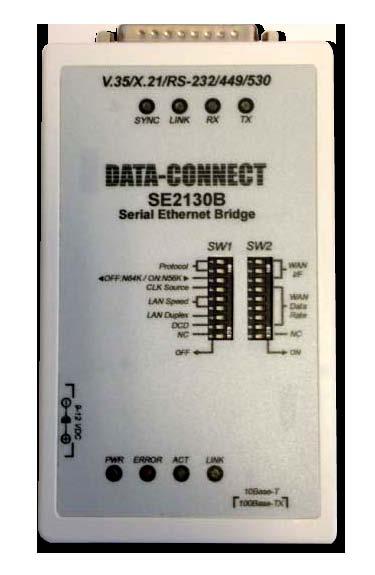
6 Unit Detail Figure 2. Unit Detail 6
7 (1) SYNC LED: Green, where ON indicates protocol is up. If OFF, first make sure physical link is up, then make sure protocol settings match. (2) LINK LED: Green, where ON indicates the presence of CTS / DSR signal on WAN connection. (3) RX LED: Green, on or flashing indicates receiving data on the WAN interface. (4) TX LED: Green, on or flashing indicates transmitting data on the WAN interface. (5) DB25 Male Connector: This connector connects to the appropriate adapter cable for connection to the various supported data interfaces. The performs in DTE mode and its WAN port connector may be connected directly to a DCE device (such as a modem). (6) SW1: Configuration setting for the bridge. (Please refer to DIP SW setting table.) (7) SW2: Configuration setting for the bridge. (Please refer to DIP SW setting table.) (8) RJ-45 Ethernet LAN Port: This is an auto-mdi/mdix port for connection to the LAN. 7
8 (9) LINK LED: (LAN) Green, indicates the Ethernet has a link to an external device. (10) ACT LED: (LAN) Green, indicates data being received from the LAN connection. (11) ERROR LED: Red, indicates an error condition as follows: ON - System Error Pulse 2 - Configuration error Pulse 3 - WAN receive has CRC errors (12) PWR LED: Green on, when external power adapter is plugged in and AC power is supplied to it. (13) DC 9~12V This jack receives power from the external DC 9~12V AC power adapter. The center pin is positive voltage. 8
9 Theory of Operation A bridge is used to connect networks locally or remotely such that they appear to the user to be the same network. An Ethernet LAN bridge will connect two LAN segments at the Data Link Layer (ISO Layer 2). At this layer, the MAC (Media Access Control) addresses, are used for low level addressing to send information to devices. The bridge builds tables of MAC addresses for each network segment based on the source and destination addresses of the packets it receives and forwards, then filters the traffic not destined for the remote network. The Ethernet-WAN bridge will connect two remote Ethernet networks over bit stream interfaces such as that of modems or DSU/CSUs. One method to do this is to use HDLC, an international standard set by the ISO, a set of protocols for carrying data over a link with error and flow control. Another method uses PPP and a third uses Cisco HDLC. The utilizes both Ethernet Bridging and encapsulation to provide a connection between LANs over bit stream architectures. The LAN side of the receives an Ethernet packet and examines its destination MAC address. If it knows the MAC is on the local network then it simply drops the packet. Otherwise, if it knows the packet destination is on the remote side, or if it cannot be determined because its MAC cannot be found in the table, then it forwards it. During forwarding, the packet is processed for transmission across the WAN link. Here is where the Ethernet packet in encapsulated. 9
10 When the HDLC or PPP packet is received on the remote side unit's data port, the packet is checked for transmission errors, then the original Ethernet packet(s) is recovered and sent out the remote's LAN port completing the transmission. Here is the typical application of the. /V35 /V35 Typical application of LAN-WAN Bridge. Many times the is commonly referred to as an Ethernet to V.35, Ethernet to X.21, or Ethernet to Datacom 'converter'. As a sales/marketing term or non-technical reference, the term is OK. However, from a technical standpoint, the term is a misnomer. The Ethernet is not "converted" to V.35, it is run "over" the V.35 link. Conversion also implies that the interface can work both ways. This is NOT the case for the LAN-WAN Bridge as the following application shows. /V35 /V35 Application NOT ALLOWED for. 10
11 Why does the previous application not work? It won't work because the application requires a bit stream to be encapsulated into Ethernet packets, or into TCP/IP and then Ethernet, for transmission across the LAN. This requires more than just manipulation at the Data Link layer (ISO Layer 2), it requires programming to include all seven layers including the Application layer. Transmitting bit stream or TDM (time division multiplexed) data over Ethernet requires a device such as an IP-Multiplexer. Please refer to the "Applications" section at the end of this manual for additional application examples. 11
12 DIP Switch Setting Tables: When the is set to internal WAN clock, SW2-4 to SW2-8 configure the data rate. If WAN clock is set external, these are ignored. DATA RATE SW2-4 SW2-5 SW2-6 SW2-7 SW2-8 SW1-3 ON SW1-3 OFF OFF OFF OFF OFF OFF 56K(1*56K) 64K(1*64K) ON OFF OFF OFF OFF 112K(2*56K) 128K(2*64K) OFF ON OFF OFF OFF 168K(3*56K) 192K(3*64K) ON ON OFF OFF OFF 224K(4*56K) 256K(4*64K) OFF OFF ON OFF OFF 280K(5*56K) 320K(5*64K) ON OFF ON OFF OFF 336K(6*56K) 384K(6*64K) OFF ON ON OFF OFF 392K(7*56K) 448K(7*64K) ON ON ON OFF OFF 448K(8*56K) 512K(8*64K) OFF OFF OFF ON OFF 504K(9*56K) 576K(9*64K) ON OFF OFF ON OFF 560K(10*56K) 640K(10*64K) OFF ON OFF ON OFF 616K(11*56K) 704K(11*64K) ON ON OFF ON OFF 672K(12*56K) 768K(12*64K) OFF OFF ON ON OFF 728K(13*56K) 832K(13*64K) ON OFF ON ON OFF 784K(14*56K) 896K(14*64K) OFF ON ON ON OFF 840K(15*56K) 960K(15*64K) ON ON ON ON OFF 896K(16*56K) 1024K(16*64K) OFF OFF OFF OFF ON 952K(17*56K) 1088K(17*64K) ON OFF OFF OFF ON 1008K(18*56K) 1152K(18*64K) OFF ON OFF OFF ON 1064K(19*56K) 1216K(19*64K) ON ON OFF OFF ON 1120K(20*56K) 1280K(20*64K) OFF OFF ON OFF ON 1176K(21*56K) 1344K(21*64K) ON OFF ON OFF ON 1232K(22*56K) 1408K(22*64K) OFF ON ON OFF ON 1288K(23*56K) 1472K(23*64K) ON ON ON OFF ON 1344K(24*56K) 1536K(24*64K) OFF OFF OFF ON ON 1400K(25*56K) 1600K(25*64K) ON OFF OFF ON ON 1456K(26*56K) 1664K(26*64K) OFF ON OFF ON ON 1512K(27*56K) 1728K(27*64K) ON ON OFF ON ON 1568K(28*56K) 1792K(28*64K) OFF OFF ON ON ON 1624K(29*56K) 1856K(29*64K) ON OFF ON ON ON 1680K(30*56K) 1920K(30*64K) OFF ON ON ON ON 1736K(31*56K) 1984K(31*64K) ON ON ON ON ON 1792K(32*56K) 2048K(32*64K) Table 1: Data Rate Settings 12
13 DIP SW1 STATE FUNCTION REMARK -4 OFF WAN CLK: External ON WAN CLK: Internal Table 2: Clock Source Setting SW1-1 SW1-2 FUNCTION REMARK OFF ON HDLC ON OFF Cisco HDLC OFF OFF PPP Table 3: Encapsulation Protocol Setting WAN INTERFACE SW2-1 SW2-2 SW2-3 TYPE OFF OFF OFF V.35 ON OFF OFF X.21/RS-530/RS-449 ON ON OFF RS-232 Table 4: WAN Interface Type Setting SW1-5 SW1-6 FUNCTION REMARK OFF OFF Auto Negotiation** ON OFF Forced 10M OFF ON Forced 100M Table 5: LAN Port Speed Setting DIP SW1 STATE FUNCTION REMARK -7 OFF Ethernet Full Duplex Ignored if Auto** ON Ethernet Half Duplex Ignored if Auto** -8 OFF flow control follows CTS / DSR ON flow control follows DCD Table 6: Miscellaneous Settings 13
14 When the leaves the factory, all DIP switch settings are set to the OFF position. Auto-negotiation: When this feature is enabled (SW1-5=OFF, SW1-6=ON), the Duplex (SW1-7) and Speed settings are ignored and are automatically determined from the LAN connection. When this feature is disabled, the Duplex and Speed settings of the LAN follow the settings of SW1-5/SW1-6 and SW1-7. Use with caution to avoid Duplex Mismatch. Protocol Selection: supports selecting one of three encapsulation protocols. When selecting HDLC, the encapsulation is per When this feature is enabled (SW1-5=OFF, SW1-6=ON), the Duplex (SW1-7) and Speed settings are ignored and are automatically Clock Selection: The inherently acts as a DTE device. A 1:1 cable is used to connect to a DCE device such as a modem or multiplexer. Clock source comes from the DCE so the clock setting must be external (SW1-4 OFF). The is also capable of acting as a DCE. In this case a crossover cable is required and clock setting (SW1-4 ON) is internal. Data rate is then set by SW2, 4~8 and provides clock source. 14
15 WAN Port Pin Assignment The following tables give the pin, circuit, function and signal direction as seen on the 's DB25M connector for each of the selectable interfaces. RS-232 and RS-530 connections may be made directly. Adapter cables are required to match the physical connectors for V.35 (MB34), X.21 (DB15) and RS-449 (DB37). a. V.24/RS-232 INTERFACE PIN ASSIGNMENT PIN CIRCUIT FUNCTION DIRECTION EIA 1 FGND Protective GND AA 2 TD Transmit data OUT BA 3 RD Receive data IN BB 4 RTS Request to send OUT CA 5 CTS Clear to send IN CB 6 DSR Data set ready IN CC 7 GND Signal ground AB 8 DCD Carrier detect IN CF 15 TC Transmit clock IN DB 17 RC Receive clock IN DD 20 DTR Data term ready OUT CD 24 XTC DTE xmit clock OUT DA Table 7: RS-232 Interface Pin Assignment SW2-1/2/3 ON/ON/OFF 15
16 b. V.35 INTERFACE PIN ASSIGNMENT PIN CIRCUIT FUNCTION DIRECTION CCITT 1 FGND Protective GND TD(A) Xmit data A OUT RD(A) Receive data A IN RTS Request to send OUT CTS Clear to send IN DSR Data set ready IN GND Signal ground DCD Data carrier detect IN RC(B) Receive clock B IN XTC(B) DTE Xmit clock B OUT TC(B) Xmit clock B IN TD(B) Xmit data B OUT TC(A) Xmit clock A IN RD(B) Receive data B IN RC(A) Receive clock A IN DTR Data terminal ready OUT XTC(A) DTE Xmit clock A OUT 113 Table 8: V.35 Interface Pin Assignment SW2-1/2/3 OFF/OFF/OFF 16
17 c. RS-449/RS-530 INTERFACE PIN ASSIGNMENT PIN CIRCUIT FUNCTION DIRECTION CCITT 1 FGND Protective GND SD(A) Xmit data A OUT RD(A) Receive data A IN RS(A) Request to send A OUT CS(A) Clear to send A IN DM(A) Data set ready A IN GND Signal ground RR(A) Data carrier detect A IN RT(B) Receive clock B IN RR(B) Data carrier detect B IN TT(B) DTE Xmit clock B OUT ST(B) Xmit clock B IN CS(B) Clear to send B IN SD(B) Xmit data B OUT ST(A) Xmit clock A IN RD(B) Receive data B IN RT(A) Receive clock A IN RS(B) Request to send B OUT TR(A) Data terminal ready A OUT DM(B) Data set ready B IN TR(B) Data terminal ready B OUT TT(A) DTE Xmit clock A OUT 113 Table 9: RS-449/RS-530 INTERFACE PIN ASSIGNMENT SW2-1/2/3 ON/OFF/OFF 17
18 d. X.21 INTERFACE PIN ASSIGNMENT PIN CIRCUIT FUNCTION DIRECTION CCITT 1 FGND Protective GND T(A) Xmit data A OUT R(A) Receive data A IN C(A) Request to send A OUT GND Signal ground I(A) Data carrier detect A IN S(B) Receive clock B IN I(B) Data carrier detect B IN T(B) Xmit data B OUT R(B) Receive data B IN S(A) Receive clock A IN C(B) Request to send B OUT 105 Table 10: X.21 INTERFACE PIN ASSIGNMENT SW2-1/2/3 ON/OFF/OFF 18
19 Cable Pin Assignments: RS-530 Cable, 25 conductor round, 1 to 1, 1m. (Use this cable for RS-232 applications as well.) Part#:58-D2FD2M007, RS-530 Cable, DB25 Female <=> DB25 Male, 1 Meter Part#:58-D2FD2F010, RS-530 Cable, DB25 Female <=> DB25 Female, 1 Meter DB25(Female) DB25(Male/Female) PIN PIN 1 <===========> 1 2 <===========> 2 3 <===========> 3 4 <===========> 4 5 <===========> 5 6 <===========> 6 7 <===========> 7 8 <===========> 8 9 <===========> 9 10 <===========> <===========> <===========> <===========> <===========> <===========> <===========> <===========> <===========> <===========> <===========> <===========> <===========> <===========> <===========> <===========> 25 19
20 V.35 Cable, multi-conductor round, 1m. Part#:58-D2FM3M001, V.35 Cable, DB25 Female MB34 Male, 1 Meter Part#:58-D2FM3F000, V.35 Cable, DB25 Female MB34 Female, 1 Meter NOTE: TWISTED PAIRS; P,S R,T U,W Y,AA V,X DB25(Female) MB34(Male/Female) PIN PIN 2 <===========> P 14 <===========> S 3 <===========> R 16 <===========> T 4 <===========> C 5 <===========> D 6 <===========> E 20 <===========> H 8 <===========> F 24 <===========> U 11 <===========> W 15 <===========> Y 12 <===========> AA 17 <===========> V 9 <===========> X 1 <===========> A 7 <===========> B 22 <===========> J 20
21 RS-449 Cables, multi-conductor round, 1m. Part#:58-D2FD3M003, RS-449 Cable, DB25 Female DB37 Male, 1M Part#:58-D2FD3F000, RS-449 Cable, DB25 Female DB37 Female, 1M DB25(Female) DB37(Male/Female) PIN PIN 1 <===========> 1 7 <===========> 19 (the following are all twisted pairs) 2 <===========> 4 14 <===========> 22 3 <===========> 6 16 <===========> 24 4 <===========> 7 19 <===========> 25 5 <===========> 9 13 <===========> 27 6 <===========> <===========> <===========> <===========> 30 8 <===========> <===========> <===========> <===========> <===========> 5 12 <===========> <===========> 8 9 <===========> 26 21
22 X.21 Cables, multi-conductor round, 1m. Part#:58-D1MD2F003, X.21 Cable, DB25 Female DB15 Male, 1M Part#:58-D1FD2F001, X.21 Cable, DB25 Female DB15 Female, 1M DB25(Female) DB15(Male/Female) PIN PIN 1 <===========> 1 7 <===========> 8 (the following are all twisted pairs) 2 <===========> 2 14 <===========> 9 3 <===========> 4 16 <===========> 11 4 <===========> 3 19 <===========> 10 8 <===========> 5 10 <===========> <===========> 6 9 <===========> 13 22
23 Sync Mode Clock Settings Interface RS-530/449/232 or V.35 X.21 Signals TD(103) RD(104) TD(103) RD(104) WAN TCLK External From TC(114) From RC(115),S WAN TCLK Internal (Internal)* Internal WAN RCLK External From RC(115) From RC(115),S WAN RCLK Internal Internal (Internal)* Table 11: SYNC Mode Clock Settings * Because the 's WAN port is DTE, the X.21 clock sources for transmit and receive are always issued from the DCE side S signal. Setting the 's X.21 clock mode to internal is not recommended. 23
24 Application Examples In the following example, the is configured for bridging over an E1 (or T1) carrier provider's network. The 's interface is set to V.35 to match the CSU/DSU unit. The CSU/DSU may be set unframed or may be set to use a fraction (n x 56 or n x 64) of the E1 (or T1) line. The CSU/DSU timing is received from the carrier provider's network so the 's timings for Tx and Rx clocks should both be set to external. In this configuration, the rate DIP settings of the re ignored. /V35 /V35 Figure 3: Bridging over E1 services 24
25 APPLICATIONS In the next example, the is setup to bridge over a PSTN's leased line. The s speed settings depend upon the speed of the leased line and the settings of the modems. The timing scheme recommended is this application is for the Tx and Rx Clocks of each unit to be set to External while the clocks of the modems are set to Internal for both or Internal for one and Loop for the other. /232 /232 Figure 4: Bridging over Synchronous leased line. 25
26 APPLICATIONS In the following example, the is paired with a G703/64K interface converter to provide connection over G Kbps services. If the G.703 transmit and receive clocks are provided by the central carrier, each G703/64K converter will be set to centra-directional line timing. Both 's will have their Tx / Rx clocks set external. Figure 6: bridge over G K services. 26
27 RMA PROCEDURE Before returning any DCE product, an RMA number must be obtained. Before asking for an RMA number, ascertain that the product was purchased from DCE. If you bought the product from a Distributor or Systems Integrator, the product should be returned to that vendor. The most convenient method to obtain an RMA authorization for a product purchased from DCE is to submit a request by fill in the form from Information required must include: -Company name -Address (including any Mail Stop or specific delivery information) -Name, contact information, and address for the technical contact(s) at your company If the above information is on your letterhead, that format is acceptable.for each item you wish to return, please include: -The product model number (usually found on the serial number tag) -The serial number for each item you wish to return -A description of the problem you are encountering -The cause of the problem (if known)a product support specialist may call to verify that the product is properly installed or may ask you to perform tests to insure that the product has actually failed. After reviewing the problem, DCE will assign an RMA number and you will be notified by or FAX. The product must be properly packed and returned to: Data Connect Enterprise 3405 Olandwood Court, Olney, MD Attn: RMA Technical Support The RMA number must be legibly displayed on the shipping carton. No RMAs will be issued without a product review. DCE will not be responsible for any product returned without an RMA number. If you believe the product may be out of warranty, include a method of payment for repairs (either a Purchase Order number or credit card number), card holder name, date of expiration on the RMA request. Repairs currently require 5 working days and are returned FEDEX ground. Contact us by mspellerberg@data-connect.com or call x25 if you should have any questions. 27
ET100A [ver2] Synchronous WAN Ethernet Bridge 10/100Base-TX Ethernet over V.35, X.21, RS-232/530/449
![ET100A [ver2] Synchronous WAN Ethernet Bridge 10/100Base-TX Ethernet over V.35, X.21, RS-232/530/449](/thumbs/72/67206529.jpg "ET100A [ver2] Synchronous WAN Ethernet Bridge 10/100Base-TX Ethernet over V.35, X.21, RS-232/530/449") ET100A [ver2] Synchronous WAN Ethernet Bridge 10/100Base-TX Ethernet over V.35, X.21, RS-232/530/449 CTC Union Technologies Co., Ltd. Neihu Technology Park Vienna Technology Center 8F, No. 60 Zhouzi St.
ET100A [ver2] Synchronous WAN Ethernet Bridge 10/100Base-TX Ethernet over V.35, X.21, RS-232/530/449 CTC Union Technologies Co., Ltd. Neihu Technology Park Vienna Technology Center 8F, No. 60 Zhouzi St.
INSTALLATION and OPERATION MANUAL
 INSTALLATION and OPERATION MANUAL Table of Contents Overview and Features.. 1 Specifications 2 Functional Block Diagram 3 Unit Detail. 4 DIP Switch Setting Tables 7 RS-232 I/F Pin Assignment.. 10 V.35
ET100/NRZ. Ethernet WAN Bridge. 10/100Base-TX Ethernet over NRZ
 ET100/NRZ Ethernet WAN Bridge 10/100Base-TX Ethernet over NRZ CTC Union Technologies Co., Ltd. NeiHu Hi-Tech Park 8F, No. 60 Zhouzi Street. Neihu, Taipei, 114 Taiwan ET100/NRZ Ethernet WAN Bridge, User
Low Speed Modems for Dial and Leased Circuits 2400E (Standalone) 2400R (Rackmount)
 2400R (Rackmount)") Low Speed Modems for Dial and Leased Circuits 2400E-030-4 (Standalone) 2400R-030-4 (Rackmount) QUALITY COMMUNICATIONS PRODUCTS Made in the U.S.A. 11-1010-002 INTRODUCTION The Data Connect ST2400E-2 and
Low Speed Modems for Dial and Leased Circuits 2400E-030-4 (Standalone) 2400R-030-4 (Rackmount) QUALITY COMMUNICATIONS PRODUCTS Made in the U.S.A. 11-1010-002 INTRODUCTION The Data Connect ST2400E-2 and
GYM Bilgi Teknolojileri
 www.fibridge-tr.com bilgi@gym-tech.net GYM Bilgi Teknolojileri E1 and V.35 Modem User Manual (Version 1.0) Beijing Fibridge Co., Ltd Table of Content 1. Overview... 1 2. Features... 1 3. Specification...
Installation and Operation Manual. Ethernet Interface for SIMREX Radio Modems. SIMREX P/N: MAN.UBRIDGE Rev. B APRIL 2005
 Installation and Operation Manual SIMREX Corporation ubridge Ethernet Interface for SIMREX Radio Modems SIMREX P/N: MAN.UBRIDGE Rev. B APRIL 2005 SIMREX CORPORATION Your Trusted Wireless Solution Provider
Miniature Asynchronous 4-Wire High Speed Modems
 ME1862A-F ME1863A-F JULY 2003 ME1862A-M ME1863A-M Miniature Asynchronous 4-Wire High Speed Modems CUSTOMER SUPPORT INFORMATION Order toll-free in the U.S.: Call 877-877-BBOX (outside U.S. call 724-746-5500)
Note: For BANDIT II, BANDIT III, or VSR-1200 specifications, see the BANDIT II, BANDIT III, and VSR-1200 Document Set. Function
 Appendix A Specifications This appendix lists the specifications for the BANDIT family of products. Note: For BANDIT II, BANDIT III, or VSR-1200 specifications, see the BANDIT II, BANDIT III, and VSR-1200
DATA CONNECT ENTERPRISE
 DATA CONNECT ENTERPRISE User s Manual IG202T and IGV23 Modem Document Number 520-01005-001 Rev. C Copyright 2009 Data Connect Enterprise. All Rights Reserved. Web site: www.data-connect.com The products
Copyright Black Box Corporation. All rights reserved.
 Copyright 1998. Black Box Corporation. All rights reserved. 1000 Park Drive Lawrence, PA 150551018 7247465500 Fax 7247460746 SAM232 Compact MARCH 1998 TS158A DB 9P cable test 1 5 6 8 7 2 3 9 4 7 6 5 4
TC1880 Series. 4/5/6/8 Channel RS-232 FIBER OPTIC MICRO MUX User's Manual
 Series 4/5/6/8 Channel RS-232 FIBER OPTIC MICRO MUX MODEL: S/N: DATE: Notice! Although every effort has been made to insure that this manual is current and accurate as of date of publication, no guarantee
USER MANUAL. MODEL 2011 High Speed Asynchronous to Synchronous Converter
 USER MANUAL MODEL 011 High Speed Asynchronous to Synchronous Converter Part# 07M011-A Doc# 0601UA Revised 03/16/94 SALES ICE (301) 975-1000 TECHNICAL SUPPORT (301) 975-1007 http://www.patton.com 1.0 WARRANTY
USER MANUAL. MODEL 1018 High Speed Short Range Modem w/ Extra Controls SALES OFFICE (301) TECHNICAL SUPPORT (301)
 TECHNICAL SUPPORT (301)") USER MANUAL MODEL 1018 High Speed Short Range Modem w/ Extra Controls Part# 07M1018-B Doc# 013021UB Revised 11/3/95 SALES OFFICE (301) 975-1000 TECHNICAL SUPPORT (301) 975-1007 1.0 WARRANTY INFORMATION
USER MANUAL MODEL 1018 High Speed Short Range Modem w/ Extra Controls Part# 07M1018-B Doc# 013021UB Revised 11/3/95 SALES OFFICE (301) 975-1000 TECHNICAL SUPPORT (301) 975-1007 1.0 WARRANTY INFORMATION
USER MANUAL. MODEL 1052 idsl Modem with RS-232 Interface. An ISO-9001 Certified Company SALES OFFICE (301) TECHNICAL SUPPORT (301)
 TECHNICAL SUPPORT (301)") USER MANUAL MODEL 1052 idsl Modem with RS-232 Interface An ISO-9001 Certified Company Part# 07M1052-B Doc# 058061UB Revised 5/24/02 SALES OFFICE (301) 975-1000 TECHNICAL SUPPORT (301) 975-1007 TABLE OF
USER MANUAL MODEL 1052 idsl Modem with RS-232 Interface An ISO-9001 Certified Company Part# 07M1052-B Doc# 058061UB Revised 5/24/02 SALES OFFICE (301) 975-1000 TECHNICAL SUPPORT (301) 975-1007 TABLE OF
Conitel ASYNC Adapter
 Conitel ASYNC Adapter TABLE OF CONTENTS SECTION 1 - DESCRIPTION...2 SECTION 2 - SPECIFICATIONS... SECTION - INSTALLATION...6 SECTION - CONTROLS AND INDICATORS...9 SECTION - NETWORK MANAGEMENT PORT...11
DATA CONNECT ENTERPRISE
 DATA CONNECT ENTERPRISE User s Manual IG202T and IGV23 Modem Document Number 520-01005-001 Rev. A DATA CONNECT Contents Contents... iii Figures... iv Chapter 1 Introduction... 5 Features...6 Applications...7
High performance access device
 High performance access device qbridge User s Manual qbridge-106 G.SHDSL Modem / Bridge Moscow 2007 2 qbridge-106. G.SHDSL Modem/Bridge. User s Manual v.3 Contents Revision history...3 1. Introduction...4
Modular E1 or Fractional E1 Access Unit. Dial-out for alarm report The E1 main link can be supplied with the following options:
 FEATURES E1 or Fractional E1 access unit Supports one data port with selectable sync data rates: n x 56, n x 64 kbps Optional sub-e1 drop & insert port for PABX connectivity Single slot supports MEGAPLEX
ERM-Mux/Plus. 4U, 10 I/O Slot Data, Ethernet, Voice E1 Managed Multiplexer. E1 Access Multiplexer. ERM-Mux/Plus.
 Access Multiplexer 4U, 10 I/O Slot Data,, Voice Managed Multiplexer The ERM-Mux/plus is a 4U 19(23)" 14 slot rack type Time Division Multiplexer for Fractional network access which is designed for non-stop
ICD105A 1008 page 1/ r001 ICD105A. Industrial RS-232 to RS-422/485 Converter
 ICD105A 1008 page 1/5 7319 r001 ICD105A Industrial RS-232 to RS-422/485 Converter Data Rates up to 115.2 Kbps 10 48 VDC Input Power Range Wide Operating Temperature 3-Way 2000V Optical Isolation Modbus
STEP X - Name of Step QUICK START GUIDE SP385A-R3, SP390A-R3 USB TO RS CONVERTER 24/7 TECHNICAL SUPPORT AT OR VISIT BLACKBOX.
 STEP X - Name of Step QUICK START GUIDE SP385A-R3, SP390A-R3 USB TO RS CONVERTER 24/7 TECHNICAL SUPPORT AT 877.877.2269 OR VISIT BLACKBOX.COM STEP 1 - Package Includes/System Requirements PACKAGE INCLUDES
MODEL DSU Kbps Rack Mount CSU/DSU OPERATOR S MANUAL. 280 I-80 West Exit 1 PO Box 1330 Verdi NV 89439
 MODEL DSU-56 56 Kbps Rack Mount CSU/DSU OPERATOR S MANUAL 280 I-80 West Exit 1 PO Box 1330 Verdi NV 89439 TEL: 775-345-8000 FAX: 775-345-8010 E-MAIL: SUPPORT @S.NET DSU-56 Rack Mount TABLE OF CONTENTS
Enhanced Mini-Chansim Model VCS-232
 Enhanced Mini-Chansim Model VCS-232 Operations Manual ViaSat Inc. 6155 El Camino Real Carlsbad, CA 92009 http://www.viasat.com SAFETY WARNING Always observe standard safety precautions during installation,
OPERATOR S MANUAL MODEL DSU-56SA. 56 Kbps Stand Alone CSU/DSU
 MODEL DSU-56SA 56 Kbps Stand Alone CSU/DSU OPERATOR S MANUAL 280 I-80 West Exit 1 PO Box 1330 Verdi NV 89439 Tel: 775-345-8000 Fax: 775-345-8010 E-mail: support @sgdi.net DSU-56SA TABLE OF CONTENTS SECTION
1205P MODEM ELIMINATOR, V.35 INSTALLATION AND OPERATIONS MANUAL. Doc #: UA Part #: 07M1205P-A (CTS ME-V.35)
") Doc #: Part #: 07M1205P-A MODEM ELIMINATOR, V.35 1205P (CTS ME-V.35) INSTALLATI AND OPERATIS MANUAL An ISO-9001 Certified Company Copyright 2000 Patton Electronics Co., All Rights Reserved PATT ELECTRICS
Doc #: Part #: 07M1205P-A MODEM ELIMINATOR, V.35 1205P (CTS ME-V.35) INSTALLATI AND OPERATIS MANUAL An ISO-9001 Certified Company Copyright 2000 Patton Electronics Co., All Rights Reserved PATT ELECTRICS
ICD200A Quick Start Guide. Convert RS-232 data signals to RS-422/485 signals in heavy industrial areas.
 Industrial Opto-Isolated RS-232 to RS-422/485 Converter Convert RS-232 data signals to RS-422/485 signals in heavy industrial areas. Rugged IP30-rated metal case for panel mounting. Quick Start Guide Customer
EtherSeries. EtherSeries CR-2. CR-2-Opto. User s Guide. Revised October 7, 2013 Firmware Version 1.X
 EtherSeries EtherSeries CR-2 & CR-2-Opto User s Guide Revised October 7, 2013 Firmware Version 1.X TABLE OF CONTENTS SECTION 1 - DESCRIPTION... 2 SECTION 2 - SPECIFICATIONS... 4 SECTION 3 - INSTALLATION...
Sender Receiver Sender
 EEE 410 Microprocessors I Spring 04/05 Lecture Notes # 19 Outline of the Lecture Interfacing the Serial Port Basics of Serial Communication Asynchronous Data Communication and Data Framing RS232 and other
USER MANUAL MODEL 2017P MODEL 2017P60. RS-232 to 20mA and. RS-232 to 60mA Current Loop Converters
 USER MANUAL MODEL 2017P RS-232 to 20mA and MODEL 2017P60 RS-232 to 60mA Current Loop Converters 07M2017P-E Doc# 073051UE Revised 5/7/96 SALES OFFICE (301) 975-1000 TECHNICAL SUPPORT (301) 975-1007 1.0
F8016. Fiber Modem for up to 4E1 /8E1/12E1/16E1 + RS232+Ethernet+ optional V.35/QFXS/QFXO
 F8016 Fiber Modem for up to 4E1 /8E1/12E1/16E1 + RS232+Ethernet+ optional V.35/QFXS/QFXO Description The fiber transmission platform is a fiber optic multiplexer with a fully new designing concept to challenge
MESR Port Industrial Modbus Gateway. Specifications Power. MESR424_r000_2913ds
 MESR424 4-Port Industrial Modbus Gateway MESR424_r000_2913ds Ethernet-Enable Modbus RS-232/422/485 MODBUS TCP, ASCII & RTU Modbus Flexibility Serial & Ethernet, Masters & Slaves Modbus Messaging Priority
485DRCI. Industrial RS-232 to RS-422/485 Converter B&B ELECTRONICS PRODUCT INFORMATION. Specifications Serial Technology
 485DRCI RS-232 RS-485 2-Wrie RS-422/485 4-Wire RS-232 CON. RS-422/485 CON. Data Rate Isolation Surge Protection Industrial Bus Source Input Voltage Power Consumption Connector p/n 7207r3 485DRCI-4108ds
User Manual A08. User Manual
 A08 TABLE OF CONTENTS TABLE OF CONTENTS... 1 1. INTRODUCTION... 2 1.1. Key Features... 3 1.2. OS Requirement... 4 1.3. Specification... 4 1.4. Packing List... 4 2. OVERVIEW... 5 2.1. LED Definition...
USER MANUAL. MODEL 1000P Non-Powered Short Haul Modem. SALES OFFICE (301) TECHNICAL SUPPORT (301)
 TECHNICAL SUPPORT (301)") USER MANUAL MODEL 1000P Non-Powered Short Haul Modem C E R T I F I E D An ISO-9001 Certified Company Part #07M1000PA Doc. #022031UA Revised 2/17/98 SALES OFFICE (301) 975-1000 TECHNICAL SUPPORT (301) 975-1007
USER MANUAL MODEL 1000P Non-Powered Short Haul Modem C E R T I F I E D An ISO-9001 Certified Company Part #07M1000PA Doc. #022031UA Revised 2/17/98 SALES OFFICE (301) 975-1000 TECHNICAL SUPPORT (301) 975-1007
User's Guide MD 14.4L Industrial Grade Dial Modems Book 1 of 2
 User's Guide MD 14.4L Industrial Grade Dial Modems Book 1 of 2 (See Book 2 for AT Commands) Document No. 49-0002-001 Rev.A TABLE of CONTENTS 1. STANDARDS...Page 2 2. PRODUCT OVERVIEW...Page 3 3. GENERAL
Product Overview. Interface Converters and Plug-in Modules
 Multi Data Digital Product Overview Interface Converters and Plug-in Modules (Ver. 2006/06) MDD - Multi Data Digital GmbH Kaiser-Friedrich-Promenade 37 61348 Bad Homburg Deutschland/Germany Tel: +49 (0)
Protocol/interface converter series
 Protocol/interface converter series E1 to 10Base-T Protocol Converter 4E1 to 10/100Mbps Ethernet Protocol Converter 8E1 to 10/100Mbps Ethernet Protocol Converter E1 to V.35 Protocol Converter Protocol
Atrie WireSpan 620. User's Manual
 Atrie WireSpan 620 User's Manual WireSpan 620 Fractional E1/Ethernet Access Unit Installation and Operation Manual (Version 1.00) CONTENTS CHAPTER 1 Introduction.. 1-1 CHAPTER 2 Installation and Setup..
User's Guide MD 14.4 Industrial Grade Dial Modems Book 1 of 2
 User's Guide MD 14.4 Industrial Grade Dial Modems Book 1 of 2 (See Book 2 for AT Commands) Document No. 49-0002-001 Rev.A TABLE of CONTENTS 1. STANDARDS...Page 2 2. PRODUCT OVERVIEW...Page 3 3. GENERAL
HS-RN. 4-Channel Low Speed Data Module with End-to-End Signaling OPERATION MANUAL INSTALLATION AND
 INSTALLATION AND OPERATION MANUAL HS-RN 4-Channel Low Speed Data Module with End-to-End Signaling Megaplex-2100/2104 Version 12, Megaplex-4100 Version 1.2 The Access Company HS-RN 4-Channel Low Speed
Contents Overview... 3 Features... 4 Applications... 4 Specifications... 5 Packing... 6 Appearance... 7 Front Panel... 7 Rear Panel...
 User's Manual Contents Overview... 3 Features... 4 Applications... 4 Specifications... 5 Packing... 6 Appearance... 7 Front Panel... 7 Rear Panel... 8 Important Safety Instructions... 9 Installation...11
Appendix A Cable Pinouts
 Appendix A Cable Pinouts This appendix lists the cables and connector pinout assignments for the cables used with the ERX-7xx models and ERX-14xx models. Topic Page SRP I/O Module 163 CT1 and CE1 I/O Modules
Model 282 Total Interface Isolation Module Reference Manual Rev. A Print Table of Contents 1.0 General Description 2.
 Page 1 of 5 Model 282 Total Interface Isolation Module Reference Manual 0315-0169 Rev. A Print 08.01.01 1.0 General Description Table of Contents 2.0 Specifications 2.1 Interface 2.2 Connectors 2.3 Isolation
xdsl Bridge WireSpan 5100B Installation Guide ATRIE TECHNOLOGY INC. (Version 1.00)
") xdsl Bridge Installation Guide (Version 1.00) ATRIE TECHNOLOGY INC. 10F, No.1, Lane 609, Sec. 5, Chung Hsin Rd., San Chung City, Taipei Hsien, Taiwan, R.O.C. Tel : (886)-999-5155 Fax : (886)-999-960 Website
xdsl Bridge Installation Guide (Version 1.00) ATRIE TECHNOLOGY INC. 10F, No.1, Lane 609, Sec. 5, Chung Hsin Rd., San Chung City, Taipei Hsien, Taiwan, R.O.C. Tel : (886)-999-5155 Fax : (886)-999-960 Website
485DRCI. Industrial RS-232 to RS-422/485 Converter PRODUCT INFORMATION B&B ELECTRONICS. Specifications Serial Technology
 485DRCI Industrial RS-232 to RS-422/485 Converter p/n 7207r5 485DRCI-2212ds page 1/5 Data Rates up to 115.2 Kbps 10 48 VDC Input Power Range Wide Operating Temperature 3-Way 2000V Optical Isolation Modbus
LC1003A IP Security CCTV Connector Installation Guide
 LC1003A IP Security CCTV Connector Installation Guide Responsibilities Black Box Corp. declines all liability for any damage that might result from any errors or omissions in this document or from improper
ISOLATED RS-232 TO RS-422/485 CONVERTER
 QUICK START GUIDE ICD400A ISOLATED RS-232 TO RS-422/485 CONVERTER 24/7 TECHNICAL SUPPORT AT 877.877.2269 OR VISIT BLACKBOX.COM STEP 1 - Specifications Complies with FCC Class B and CE requirements. Withstands
ASYNC Sharing Unit TABLE OF CONTENTS SECTION 1 - DESCRIPTION...2 SECTION 2 - SPECIFICATIONS...5 SECTION 3 - INSTALLATION...7
 ASYNC Sharing Unit TABLE OF CONTENTS SECTION 1 - DESCRIPTION... SECTION - SPECIFICATIONS... SECTION - INSTALLATION... SECTION - FRONT PANEL CONTROLS AND INDICATORS...9 SECTION - NETWORK MANAGEMENT PORT...10
Cable Pinouts. SRP I/O Module
 Cable Pinouts A This appendix lists the cables and connector pinout assignments for the cables used with the ERX-7xx models and ERX-14xx models. Topic Page SRP I/O Module A-1 CT1 and CE1 I/O Modules A-4
Data Sheet and Installation
 Data Sheet and Installation TinyBridge-100 Miniature Remote Fast Ethernet Bridge The Access Company Features High-performance miniature remote bridge for Fast Ethernet extension Wire-speed WAN throughput:
USER MANUAL. MODELS 1205 and 1205/34. Synchronous V.35 Modem Eliminators
 USER MANUAL MODELS 1205 and 1205/34 Synchronous V.35 Modem Eliminators An ISO-9001 Certified Company Part #07M1205-D Doc #049021U, Rev. E Revised 1/22/08 SALES OFFICE (301) 975-1000 TECHNICAL SUPPORT (301)
Mini Driver V (Mini Driver MP with 5-Screw Terminal Block) MINI DRIVER MP
 MINI DRIVER MP") MAY 1997 ME745A-F-R2 ME745A-M-R2 ( Driver MP with 5-Screw Terminal Block) MINI DRIVER MP CUSTOMER SUPPORT INFORMATION Order toll-free in the U.S. 24 hours, 7 A.M. Monday to midnight Friday: 877-877-BBOX
MAY 1997 ME745A-F-R2 ME745A-M-R2 ( Driver MP with 5-Screw Terminal Block) MINI DRIVER MP CUSTOMER SUPPORT INFORMATION Order toll-free in the U.S. 24 hours, 7 A.M. Monday to midnight Friday: 877-877-BBOX
USER MANUAL MODEL Bidirectional (IEEE-1284) Line Driver/Converter
 Line Driver/Converter") USER MANUAL MODEL 2030 Bidirectional (IEEE-1284) Line Driver/Converter An ISO-9001 Certified Company Part # 07M2030-B Doc. #102121U, Rev. C Revised 1/22/08 SALES OFFICE (301) 975-1000 TECHNICAL SUPPORT
USER MANUAL MODEL 2030 Bidirectional (IEEE-1284) Line Driver/Converter An ISO-9001 Certified Company Part # 07M2030-B Doc. #102121U, Rev. C Revised 1/22/08 SALES OFFICE (301) 975-1000 TECHNICAL SUPPORT
RS-232 to RS-422/485 Converter with 3KV Isolation Protection
 RS-232 to RS-422/485 Converter with 3KV Isolation Protection (ID-SC0E11-S1) User s Manual 04-0779A - 1 - Introduction The serial converter converts RS 232 signals to RS 422 or RS 485 and extends the communication
RC801-60B-FV35, RC803-60B-FV35, RC805-60B-FV35 Series Standalone V.35+E1 Dual Interface Fiber Optic Modem. User Manual REV.N
 RC801-60B-FV35, RC803-60B-FV35, RC805-60B-FV35 Series Standalone V.35+E1 Dual Interface Fiber Optic Modem User Manual REV.N Raisecom Technology Co., Ltd. (05/2006) 1. Cautions Please read the following
USER MANUAL MODEL CopperLink Ethernet Extender SALES OFFICE (301) TECHNICAL SUPPORT (301)
 TECHNICAL SUPPORT (301)") USER MANUAL MODEL 2155 CopperLink Ethernet Extender An ISO-9001Certified Company Part# 07M2155 Doc# 032111U Rev. A Revised 2/12/03 SALES OFFICE (301) 975-1000 TECHNICAL SUPPORT (301) 975-1007 CONTENTS
USER MANUAL MODEL 2155 CopperLink Ethernet Extender An ISO-9001Certified Company Part# 07M2155 Doc# 032111U Rev. A Revised 2/12/03 SALES OFFICE (301) 975-1000 TECHNICAL SUPPORT (301) 975-1007 CONTENTS
Serial Communications Accessories SITRANS RD200/300. Operating Instructions 05/2013 SITRANS
 Serial Communications Accessories SITRANS RD200/300 Operating Instructions 05/2013 SITRANS Siemens Auto SIT SITRANS RD300RANS RD300 Safety Guidelines: Warning notices must be observed to ensure personal
USER MANUAL EOe-1. 10/100Base Ethernet over G.703 Unframed E1
 USER MANUAL EOe-1 10/100Base Ethernet over G.703 Unframed E1 CTC Union Technologies Co., Ltd. Far Eastern Vienna Building Neihu Technology Park 8F, No. 60 ZhouZi St. Neihu, Taipei, 114 Taiwan EOe-1 Ethernet
Overview of the Cisco 2524 and Cisco 2525 Routers
 CHAPTER 1 Overview of the Cisco 2524 and Cisco 2525 Routers The Cisco 2524 and Cisco 2525 routers provide LAN and WAN access in a low-cost modular router platform that can grow with your internetworking
Bluetooth to RS-232&RS422/485. EX-9132B/BI Bluetooth Adapter Operation Manual
 Bluetooth to RS-232&RS422/485 EX-9132B/BI Bluetooth Adapter Operation Manual First Edition, Jun 2008 Table of Contents 1. Introduction 2 2. Package checklist 3 3. Product Specification 4 4. Product Panel
Miniature Asynchronous Modems
 ME615A MARCH 2007 ME615AE ME616A ME616AE Miniature Asynchronous Modems CUSTOMER SUPPORT INFORMATION Order toll-free in the U.S.: Call 877-877-BBOX (outside U.S. call 724-746-5500) FREE technical support
USER MANUAL E1U-ET100. Ethernet over Unframed E1 Bridge Line Card For ERM01
 USER MANUAL E1U-ET100 Ethernet over Unframed E1 Bridge Line Card For ERM01 CTC Union Technologies Co., Ltd. Far Eastern Vienna Technology Center (Neihu Technology Park) 8F, No. 60, Zhouzi St. Neihu, Taipei,
IDS-141A/181A. Industrial 4-port/8-port slim type serial to Ethernet device server. Features. Introduction. DS-Tool
 4/8 Port v1.5 / Dec, 2011 Features 4-port/8-port slim type serial to Ethernet device server Operating Modes : Virtual Com, Tunnel, TCP Server, TCP Client, UDP Multiple host devices : 5 host devices: Virtual
4xT1/E1 i nline probe ASE With LinkSafe capabilities
 Visual UpTime Select ASE model 807-0115 4xT1/E1 i nline probe ASE With LinkSafe capabilities Key features Four management ports MLPPP support on IP Transport software Inband management capability LinkSafe
PPP. Point-to-Point Protocol
 PPP Point-to-Point Protocol 1 Introduction One of the most common types of WAN connection is the point-to-point connection. Point-to-point connections are used to connect LANs to service provider WANs,
USER MANUAL FOM02-MUX
 USER MANUAL FOM02-MUX Fiber Optical Multiplexer Standalone / Rack Type 4, 8, 12 or 16 Channel Modular Design G.703 E1, T1(DS1) Datacom V.35, X.21, RS-530, RS-449, RS-232 Ethernet 10/100Base-TX Bridge SNMP
RS-232 Connector Pin Assignments
 APPENDIXB This appendix lists the connector pin assignments for the CDEs, and includes the following sections: Serial Console-Interface, page B- Ethernet, page B- Cable Pin Assignments, page B- Serial
The Tri-State Box User s Manual
 ESL Model 700 EIA RS-232 Interface Analyzer Cat No. 301030 The Tri-State Box User s Manual 36 Western Industrial Drive Cranston, RI 02921 Tel: 401-943-1164 www.electrostandards.com Pub. 2903-03 Use and
Serial Communication Converters & Adapters Instruction Manual
 Serial Communication Converters & Adapters Instruction Manual RS-232 to RS-422/485 Converter Isolated RS-232 to RS-422/485 Converter USB to RS-232 Converter USB to RS-422/485 Converter Isolated USB to
RS-232/422/485 to Copper or Fiber. Ethernet Converter. User s Manual
 RS-232/422/485 to Copper or Fiber Ethernet Converter User s Manual Table Of Contents TABLE OF CONTENTS... 1 INTRODUCTION... 3 PRODUCT OVERVIEW... 3 PRODUCT FEATURES... 3 PACKING LIST... 4 LED INDICATORS...
LLM-336S.Eth. Introduction. Features. Industrial Leased line modem with internal Ethernet Bridge.
 LLM-336.Eth Industrial Leased line modem with internal Ethernet Bridge. LLM-336D.Eth LLM-336S.Eth Introduction The MuLogic LLM-336.Eth is a voiceband modem combined with an Ethernet bridge for connecting
IML 560 USER GUIDE. Low Power 56Kbps Industrial modem. Version 1.2. December 6, AYANTRA Inc.
 IML 560 USER GUIDE Low Power 56Kbps Industrial modem Version 1.2 December 6, 2002 AYANTRA Inc. Revision History Date Version Description By November 18, 2002 1.1 Initial Release - December 6, 2002 1.2
DSU 5600 Data Service Unit USER MANUAL
 DSU 5600 Data Service Unit USER MANUAL 61200.078L1-1D May 1997 901 Explorer Boulevard P.O. Box 140000 Huntsville, AL 35814-4000 Phone: (205) 963-8000 1997 ADTRAN, Inc. All rights reserved. Printed in USA.
E1/T1 Rate Converters
 MT1100A MT1100C MT1101A-DC MT1102A-DC JULY 2003 MT1100A-DC MT1101A MT1102A MT1102C E1/T1 Rate Converters CUSTOMER SUPPORT INFORMATION Order toll-free in the U.S.: Call 877-877-BBOX (outside U.S. call 724-746-5500)
FOM01-MUX. User Manual
 FOM01-MUX User Manual The information contained in this document is subject to change without prior notice. TRADEMARKS Microsoft is a registered trademark of Microsoft Corp. HyperTerminal is a registered
RS-232 SERIAL INTERFACE PHOTOELECTRIC ISOLATOR
 RS-232 SERIAL INTERFACE PHOTOELECTRIC ISOLATOR User Manual DA-70163 I. Summary With adoption of advanced photoelectric isolation technology, RS-232 Serial Interface Photoelectric Isolator, also named Serial
FE1&10/100BASE-T Bridge
 USER MANUAL F&10/100BASE-T Bridge Contents 1. Product description... 2 2. Main features... 2 3. Technical specifications... 3 4. Installation and panel description... 4 4.1 Unpacking(stand alone F&10/100BASE-T
ME500A BLACK BOX SPECIFICATIONS: BOTTOM OF UNIT INTRODUCTION: CONFIGURATION: Async Sync Industrial Line Driver PWR TX RX RTS CD. DB25 Female Conn.
 ME500A DB25 Female Conn. PWR TX RX BLACK BOX Async Sync Industrial Line Driver RTS CD PWR TX RX RTS CD ERROR TEST 511 511E Remote Normal Local ERROR TEST SPECIFICATIS: Transmission Format: Synchronous
Chapter 2. Hardware Description. 2.1 Chassis. Note: For product specifications, see Appendix A, Specifications.
 Chapter 2 Hardware Description This chapter provides information on the hardware for the BANDIT product family. Note: For product specifications, see Appendix A, Specifications. 2.1 Chassis The chassis
USER S MANUAL. PH232Ex1. #1 RS-232 Serial Port to Ethernet, Terminal Server/Client. Doc No: PH232Ex1-UM-001 IPEX. (IP Electronix)
") USER S MANUAL PH232Ex1 Doc No: PH232Ex1-UM-001 #1 RS-232 Serial Port to Ethernet, Terminal Server/Client IPEX (IP Electronix) Contents 1. INTRODUCTION... 3 2. SPECIFICATIONS... 3 3. PACKAGE CHECKLIST...
USER S MANUAL PH232Ex1 Doc No: PH232Ex1-UM-001 #1 RS-232 Serial Port to Ethernet, Terminal Server/Client IPEX (IP Electronix) Contents 1. INTRODUCTION... 3 2. SPECIFICATIONS... 3 3. PACKAGE CHECKLIST...
Select a Data Communication Interface
 Printer Setup and Operation Select a Data Communication Interface Select a Data Communication Interface You may connect your print engine to a computer using one or more of the available connections. The
MDI/MDIX) FEP-32005T-2
 FEP-32005T-2") TM Mico-Switch/5 5 Port 10/100Base-TX Switch (Auto MDI/MDIX) FEP-32005T-2 U SER S M ANUAL (Auto MDI/MDIX) FEP-32005T-2 TM TM Package Contents Package contents include the following: Micro-Switch/5; 5 Port
TM Mico-Switch/5 5 Port 10/100Base-TX Switch (Auto MDI/MDIX) FEP-32005T-2 U SER S M ANUAL (Auto MDI/MDIX) FEP-32005T-2 TM TM Package Contents Package contents include the following: Micro-Switch/5; 5 Port
Overview encapsulation hdlc show interface show controllers show interface debug PPP
 PPP CCNA 4 Overview Explain serial communication Describe and give an example of TDM Identify the demarcation point in a WAN Describe the functions of the DTE and DCE Discuss the development of HDLC encapsulation
Installation Guide. 100BASE-TX/100BASE-FX Fast Ethernet Media Converter NC-200FT/FC. -1-iIiNC-200FT/FC P/N:
 Installation Guide 100BASE-TX/100BASE-FX Fast Ethernet Media Converter NC-200FT/FC -1-iIiNC-200FT/FC P/N:750-0166-001 Table le of Contents General Description...3 Specifications...4 Connectors & Cables...5
RCS/6000. Hardware. Manual
 RCS/6000 Hardware Manual Document number 80-001052-6 Revision A RCS/6000 Hardware Manual Document part number 80-001052-6 Revision History Date Revision Description 4/10/01 A Initial production release
NCOM SERIAL DEVICE SERVER 4XX SERIES USER S MANUAL
 NCOM SERIAL DEVICE SERVER 4XX SERIES USER S MANUAL 2017-07-07 Edition Titan Electronics Inc. Web: www.titan.tw Contents 1. INTRODUCTION... 4 1.1 Key Features... 5 1.2 Specifications... 6 2. PANEL LAYOUT
ME778C-RJ45 MAIN MODULE (FRONT CARD) MAIN MODULE. Line: RJ-45. Line: RJ-45 INTERFACE MODULE (REAR CARD) Serial: 10-Pin RJ.
 MAIN MODULE. Line: RJ-45. Line: RJ-45 INTERFACE MODULE (REAR CARD) Serial: 10-Pin RJ.") ME778C-RJ45 Line: RJ-45 MAIN MODULE Mini Driver MP Card ME778C-RJ45 Power Line: RJ-45 Unit A -TD -RD -CD -TD Serial: 10-Pin RJ INTERFACE MODULE (REAR CARD) Unit B -RD -CD Serial: 10-Pin RJ LO Z A HI Z
ME778C-RJ45 Line: RJ-45 MAIN MODULE Mini Driver MP Card ME778C-RJ45 Power Line: RJ-45 Unit A -TD -RD -CD -TD Serial: 10-Pin RJ INTERFACE MODULE (REAR CARD) Unit B -RD -CD Serial: 10-Pin RJ LO Z A HI Z
Cable Specifications. Interface Specifications. Fiber-Optic Specifications APPENDIXB
 APPENDIXB This appendix lists the cable specifications for supported modules on the Cisco 7600 series router. The following signal summaries are contained in this appendix: Interface Specifications, page
SCADA Point-to-Point Multiplexer
 SCADA Point-to-Point Multiplexer TABLE OF CONTENTS SECTION 1 - DESCRIPTION...2 SECTION 2 - SPECIFICATIONS... SECTION - INSTALLATION... SECTION - CONTROLS AND INDICATORS...9 SECTION - NETWORK MANAGEMENT
APPLICATION NOTE. Product Application Note: APN032
 APPLICATION NOTE Maximise port density and increase data rates when routing asymmetric Ethernet links via satellite modems. The Application Summary With the explosive worldwide growth of the Internet,
Quick Start Guide Elinx ESW500 Series. Managed Din Rail Ethernet Switch
 Quick Start Guide Elinx ESW500 Series Managed Din Rail Ethernet Switch ESW500 Series Documentation Number: ESW500series-1012qsg International Headquarters: 707 Dayton Road Ottawa, IL 61350 USA Phone (815)
EiconCard S90. for PCI-Compatible Bus. Installation Guide
 EiconCard S90 for PCI-Compatible Bus Installation Guide 203-187-01 First Edition (March 1998) Eicon, EiconCard, and EiconCard S90 are trademarks of Eicon Technology Corporation. Changes are periodically
FCC Information. RoHS This product is RoHS compliant. SJ/T The following contains information that relates to China.
 FCC Information This equipment has been tested and found to comply with the limits for a Class B digital device, pursuant to Part 15 of the FCC Rules. These limits are designed to provide reasonable protection
NetBiter Serial Server User Manual
 User Manual IntelliCom Innovation AB Linjegatan 3D SE-302 50 Halmstad SWEDEN Phone +46 35 18 21 70 Fax +46 35 17 29 09 email info@intellicom.se web www.intellicom.se Revision List Revision Date Author
FCD-E1E Managed E1 and Fractional E1 Access Device
 FCD-E1E E1 main link and sublink supporting both framed and unframed signals One data port with selectable sync data rates of n 64 kbps Optional sub-e1 drop-and-insert port Optional Ethernet 10/100BaseT
MGate TM EIP3000 DF1 to EtherNet/IP Gateway User s Manual
 MGate TM EIP3000 DF1 to EtherNet/IP Gateway User s Manual First Edition, June 2009 www.moxa.com/product 2009 Moxa Inc. All rights reserved. Reproduction without permission is prohibited. MGate EIP3000
ZM24x Quick-Connect Industrial Modem. User s Manual
 ZM24x Quick-Connect Industrial Modem User s Manual Version 1.1 2004 ZYPEX, Inc. All Rights Reserved 1 ZM24x Quick-Connect Industrial Modem Since the equipment explained in this manual has a variety of
PDS200 Power over Ethernet Device Server User Manual
 PDS200 Power over Ethernet Device Server User Manual ABOUT PDS200 is an external usage Power over Ethernet Device Server (Serial-to- Ethernet converter). It includes the function of GIGA-TMS s products-
TRP-C37. Ethernet to RS232/422/485 Converter. User s Manual. Printed Apr.2014 Rev 1.3
 TRP-C37 Ethernet to RS232/422/485 Converter User s Manual Printed Apr.2014 Rev 1.3 Trycom Technology Co.,Ltd No.35, Zhongxing Rd., Guishan Township, Taoyuan County 333, Taiwan. Tel : 886-3-350-3351 Fax:
Lantech LSC-1102B SERIAL TO TCPIP CONVERTER. User Manual
 Lantech LSC-1102B SERIAL TO TCPIP CONVERTER User Manual V1.0 Sep 2016 Table of Contents 1. Introduction 3 Overview 4 Product Specifications 8 2. Description & Installation 10 Product Panel Views 10 LED