Introduction to OSPF
|
|
|
- Delphia Hampton
- 6 years ago
- Views:
Transcription


1 Campus Networking Introduction to OSPF Workshop Campus Layer-2 Networking Network Workshop Design These materials are licensed under the Creative Commons Attribution-Noncommercial 3.0 Unported license (
2 Layer 2 Concepts Layer 2 protocols basically control access to a shared medium (copper, fiber, electro-magnetic waves) Ethernet is the de-facto standard today Reasons: Simple Cheap Manufacturers keep making it faster
3 Ethernet Functions Source and Destination identification MAC addresses Detect and avoid frame collisions Listen and wait for channel to be available If collision occurs, wait a random period before retrying This is called CASMA-CD: Carrier Sense Multiple Access with Collision Detection
4 Switched Star Topology Benefits It s modular: Independent wires for each end node Independent traffic in each wire A second layer of switches can be added to build a hierarchical network that extends the same two benefits above ALWAYS DESIGN WITH MODULARITY IN MIND


5 Hub Hub A frame sent by one node is always sent to every other node. Hubs are also called repeaters because they just repeat what they hear.
6 Switch Learns the location of each node by looking at the source address of each incoming frame, and builds a forwarding table Forwards each incoming frame only to the port where the destination node is Reduces the collision domain Makes more efficient use of the wire Nodes don t waste time checking frames not destined to them

7 Switch Forwarding Table Address AAAAAAAAAAAA 1 Port BBBBBBBBBBBB 5 Switch A B
8 Switches and Broadcast A switch broadcasts some frames: When the destination address is not found in the table When the frame is destined to the broadcast address (FF:FF:FF:FF:FF:FF) When the frame is destined to a multicast ethernet address So, switches do not reduce the broadcast domain!
9 Switch vs. Router Routers more or less do with IP packets what switches do with Ethernet frames A router looks at the IP packet destination and checks its routing table to decide where to forward the packet Some differences: IP packets travel inside ethernet frames IP networks can be logically segmented into subnets Switches do not usually know about IP, they only deal with Ethernet frames
10 Switch vs. Router SWITCH Layer-2 device Uses MAC addresses Passes Ethernet Frames ROUTER Layer-3 device Uses IP Addresses Passes IP Packets
11 Switch vs. Router Routers do not forward Ethernet broadcasts. So: Switches reduce the collision domain Routers reduce the broadcast domain This becomes really important when trying to design hierarchical, scalable networks that can grow sustainably
12 Traffic Domains Router Switch Switch Hub Hub Hub Hub Broadcast Domain Collision Domain
13 Traffic Domains Try to eliminate collision domains Get rid of hubs! Try to keep your broadcast domain limited to no more than 250 simultaneously connected hosts Segment your network using routers
14 Layer 2 Network Design Guidelines Always connect hierarchically If there are multiple switches in a building, use an aggregation switch Locate the aggregation switch close to the building entry point (e.g. fiber panel) Locate edge switches close to users (e.g. one per floor) Max length for Cat5 is 100 meters


15 Building Network Level 4 Level 3 Level 2 Level 1

16 Connect buildings hierarchically
17 Switching Architectures Any Questions?
18 Virtual LANs (VLANs) Allow us to split switches into separate (virtual) switches Only members of a VLAN can see that VLAN s traffic Inter-vlan traffic must go through a router
19 Local VLANs 2 VLANs or more within a single switch Edge ports, where end nodes are connected, are configured as members of a VLAN The switch behaves as several virtual switches, sending traffic only within VLAN members
20 Local VLANs Switch VLAN X VLAN Y Edge ports VLAN X nodes VLAN Y nodes
21 VLANs across switches Two switches can exchange traffic from one or more VLANs Inter-switch links are configured as trunks, carrying frames from all or a subset of a switch s VLANs Each frame carries a tag that identifies which VLAN it belongs to
22 802.1Q The IEEE standard that defines how ethernet frames should be tagged when moving across switch trunks This means that switches from different vendors are able to exchange VLAN traffic.

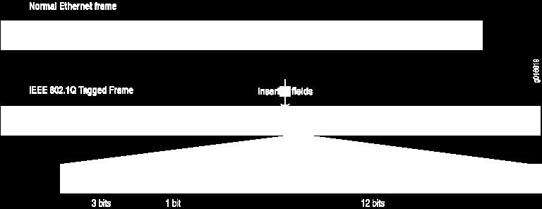
23 802.1Q tagged frame


24 VLANs across switches Tagged Frames 802.1Q Trunk Trunk Port VLAN X VLAN Y Edge Ports VLAN X VLAN Y This is called VLAN Trunking
25 Tagged vs. Untagged Edge ports are not tagged, they are just members of a VLAN You only need to tag frames in switch-toswitch links (trunks), when transporting multiple VLANs A trunk can transport both tagged and untagged VLANs As long as the two switches agree on how to handle those
26 VLANs increase complexity You can no longer just replace a switch Now you have VLAN configuration to maintain Field technicians need more skills You have to make sure that all the switchto-switch trunks are carrying all the necessary VLANs Need to keep in mind when adding/removing VLANs
27 Good reasons to use VLANs You want to segment your network into multiple subnets, but can t buy enough switches Hide sensitive infrastructure like IP phones, building controls, etc. Separate control traffic from user traffic Restrict who can access your switch management address
28 Bad reasons to use VLANs Because you can, and you feel cool J Because they will completely secure your hosts (or so you think) Because they allow you to extend the same IP network over multiple separate buildings This is actually very common, but a bad idea
29 Do not build VLAN spaghetti Extending a VLAN to multiple buildings across trunk ports Bad idea because: Broadcast traffic is carried across all trunks from one end of the network to another Broadcast storm can spread across the extent of the VLAN, and affect all VLANS! Maintenance and troubleshooting nightmare
30 VLANs Any Questions?
31 Link Aggregation Also known as port bundling, link bundling You can use multiple links in parallel as a single, logical link For increased capacity For redundancy (fault tolerance) LACP (Link Aggregation Control Protocol) is a standardized method of negotiating these bundled links between switches
32 LACP Operation Two switches connected via multiple links will send LACPDU packets, identifying themselves and the port capabilities They will then automatically build the logical aggregated links, and then pass traffic. Switch ports can be configured as active or passive
33 LACP Operation 100 Mbps Switch A Switch B 100 Mbps LACPDUs Switches A and B are connected to each other using two sets of Fast Ethernet ports LACP is enabled and the ports are turned on Switches start sending LACPDUs, then negotiate how to set up the aggregation


34 LACP Operation 100 Mbps Switch A Switch B 100 Mbps 200 Mbps logical link The result is an aggregated 200 Mbps logical link The link is also fault tolerant: If one of the member links fail, LACP will automatically take that link off the bundle, and keep sending traffic over the remaining link
35 Link Aggregation Any Questions?
36 Switching Loop Switch A Switch B When there is more than one path between two switches Switch C What are the potential problems?
37 Switching Loop If there is more than one path between two switches: Forwarding tables become unstable Source MAC addresses are repeatedly seen coming from different ports Switches will broadcast each other s broadcasts All available bandwidth is utilized Switch processors cannot handle the load
38 Switching Loop Switch A Switch B Switch C Node1 sends a broadcast frame (e.g. an ARP request) Node 1
39 Switching Loop Switch A Switch B Switches A, B and C broadcast node 1 s frame out every port Switch C Node 1
40 Switching Loop Switch A Switch B But they receive each other s broadcasts, which they need to forward again out every port! Switch C The broadcasts are amplified, creating a broadcast storm Node 1
41 Good Switching Loops But you can take advantage of loops! Redundant paths improve resilience when: A switch fails Wiring breaks How to achieve redundancy without creating dangerous traffic loops?


42 What is a Spanning Tree Given a connected, undirected graph, a spanning tree of that graph is a subgraph which is a tree and connects all the vertices together. A single graph can have many different spanning trees.
43 Spanning Tree Protocol The purpose of the protocol is to have bridges dynamically discover a subset of the topology that is loop-free (a tree) and yet has just enough connectivity so that where physically possible, there is a path between every switch
44 Spanning Tree Protocol Several flavors: Traditional Spanning Tree (802.1d) Rapid Spanning Tree or RSTP (802.1w) Multiple Spanning Tree or MSTP (802.1s)
45 Traditional Spanning Tree (802.1d) Switches exchange messages that allow them to compute the Spanning Tree These messages are called BPDUs (Bridge Protocol Data Units) Two types of BPDUs: Configuration Topology Change Notification (TCN)
46 Traditional Spanning Tree (802.1d) First Step: Decide on a point of reference: the Root Bridge The election process is based on the Bridge ID, which is composed of: The Bridge Priority: A two-byte value that is configurable The MAC address: A unique, hardcoded address that cannot be changed.
47 Root Bridge Selection (802.1d) Each switch starts by sending out BPDUs with a Root Bridge ID equal to its own Bridge ID I am the root! Received BPDUs are analyzed to see if a lower Root Bridge ID is being announced If so, each switch replaces the value of the advertised Root Bridge ID with this new lower ID Eventually, they all agree on who the Root Bridge is
48 Root Bridge Selection (802.1d) AA Swtich A Switch B BB Switch C CC All switches have the same priority. Who is the elected root bridge?
49 Root Port Selection (802.1d) Now each switch needs to figure out where it is in relation to the Root Bridge Each switch needs to determine its Root Port The key is to find the port with the lowest Root Path Cost The cumulative cost of all the links leading to the Root Bridge
50 Root Port Selection (802.1d) Each link on a switch has a Path Cost Inversely proportional to the link speed e.g. The faster the link, the lower the cost Link Speed STP Cost 10 Mbps Mbps 19 1 Gbps 4 10 Gbps 2
51 Root Port Selection (802.1d) Root Path Cost is the accumulation of a link s Path Cost and the Path Costs learned from neighboring Switches. It answers the question: How much does it cost to reach the Root Bridge through this port?
52 Root Port Selection (802.1d) 1. Root Bridge sends out BPDUs with a Root Path Cost value of 0 2. Neighbor receives BPDU and adds port s Path Cost to Root Path Cost received 3. Neighbor sends out BPDUs with new cumulative value as Root Path Cost 4. Other neighbor s down the line keep adding in the same fashion
53 Root Port Selection (802.1d) On each switch, the port where the lowest Root Path Cost was received becomes the Root Port This is the port with the best path to the Root Bridge
54 Root Port Selection (802.1d) AA Cost=19 1 Swtich A 2 Cost= Switch B BB 2 2 Cost=19 Switch C CC What is the Path Cost on each Port? What is the Root Port on each switch?


55 Root Port Selection (802.1d) AA Root Port Cost=19 1 Swtich A 2 Cost= Root Port Switch B BB 2 2 Cost=19 Switch C CC
56 Electing Designated Ports (802.1d) OK, we now have selected root ports but we haven t solved the loop problem yet, have we The links are still active! Each network segment needs to have only one switch forwarding traffic to and from that segment Switches then need to identify one Designated Port per link The one with the lowest cumulative Root Path Cost to the Root Bridge
57 Electing Designated Ports(802.1d) AA Cost=19 1 Swtich A 2 Cost= Switch B BB 2 2 Cost=19 Switch C CC Which port should be the Designated Port on each segment?
58 Electing Designated Ports (802.1d) Two or more ports in a segment having identical Root Path Costs is possible, which results in a tie condition All STP decisions are based on the following sequence of conditions: Lowest Root Bridge ID Lowest Root Path Cost to Root Bridge Lowest Sender Bridge ID Lowest Sender Port ID
 Designated Port Cost=19 32678.")


59 Electing Designated Ports(802.1d) Designated Port Cost= AA 1 Swtich A 2 Cost=19 Designated Port 1 1 Switch B BB 2 2 Cost=19 Switch C CC Designated Port In the B-C link, Switch B has the lowest Bridge ID, so port 2 in Switch B is the Designated Port
60 Blocking a port Any port that is not elected as either a Root Port, nor a Designated Port is put into the Blocking State. This step effectively breaks the loop and completes the Spanning Tree.
61 Designated Ports on each segment (802.1d) AA Cost=19 1 Swtich A 2 Cost=19 Switch B BB Cost=19 Switch C CC Port 2 in Switch C is then put into the Blocking State because it is neither a Root Port nor a Designated Port
62 Spanning Tree Protocol States Disabled Port is shut down Blocking Not forwarding frames Receiving BPDUs Listening Not forwarding frames Sending and receiving BPDUs
63 Spanning Tree Protocol States Learning Not forwarding frames Sending and receiving BPDUs Learning new MAC addresses Forwarding Forwarding frames Sending and receiving BPDUs Learning new MAC addresses
64 STP Topology Changes Switches will recalculate if: A new switch is introduced It could be the new Root Bridge! A switch fails A link fails
65 Root Bridge Placement Using default STP parameters might result in an undesired situation Traffic will flow in non-optimal ways An unstable or slow switch might become the root You need to plan your assignment of bridge priorities carefully


66 Bad Root Bridge Placement Out to router BB Swtich B Switch D DD Root Bridge CC Switch C Switch A AA


67 Good Root Bridge Placement Alernative Root Bridge Out to standby router Out to active router Root Bridge BB Swtich B Switch D DD CC Switch C Switch A AA
68 STP Design Guidelines Enable spanning tree even if you don t have redundant paths Always plan and set bridge priorities Make the root choice deterministic Include an alternative root bridge If possible, do not accept BPDUs on end user ports Apply BPDU Guard or similar where available
69 802.1d Convergence Speeds Moving from the Blocking state to the Forwarding State takes at least 2 x Forward Delay time units (~ 30 secs.) This can be annoying when connecting end user stations Some vendors have added enhancements such as PortFast, which will reduce this time to a minimum for edge ports Never use PortFast or similar in switch-to-switch links Topology changes tipically take 30 seconds too This can be unacceptable in a production network
70 Rapid Spanning Tree (802.1w) Convergence is much faster Communication between switches is more interactive Edge ports don t participate Edge ports transition to forwarding state immediately If BPDUs are received on an edge port, it becomes a non-edge port to prevent loops
71 Questions? Thank you.
Campus Networking Workshop. Layer 2 engineering Spanning Tree and VLANs
 Campus Networking Workshop Layer 2 engineering Spanning Tree and VLANs Switching Loop When there is more than one path between two switches What are the potential problems? Switching Loop If there is more
Layer 2 Engineering Spanning Tree
 Layer 2 Engineering Spanning Tree Campus Network Design & Operations Workshop These materials are licensed under the Creative Commons Attribution-NonCommercial 4.0 International license (http://creativecommons.org/licenses/by-nc/4.0/)
Layer 2 Engineering VLANs
 Layer 2 Engineering VLANs Campus Network Design & Operations Workshop These materials are licensed under the Creative Commons Attribution-NonCommercial 4.0 International license (http://creativecommons.org/licenses/by-nc/4.0/)
Top-Down Network Design
 Top-Down Network Design Chapter Five Designing a Network Topology Original slides copyright by Cisco Press & Priscilla Oppenheimer Network Topology Design Issues Hierarchy Redundancy Modularity Well-defined
Implement Spanning Tree Protocols-PART-I. LAN Switching and Wireless Chapter 5 Modified by Tony Chen 05/01/2008
 Implement Spanning Tree Protocols-PART-I LAN Switching and Wireless Chapter 5 Modified by Tony Chen 05/01/2008 ITE I Chapter 6 2006 Cisco Systems, Inc. All rights reserved. Cisco Public 1 Notes: If you
CCNA 3 (v v6.0) Chapter 3 Exam Answers % Full
 Chapter 3 Exam Answers % Full") CCNA 3 (v5.0.3 + v6.0) Chapter 3 Exam Answers 2017 100% Full ccnav6.com /ccna-3-v5-0-3-v6-0-chapter-3-exam-answers-2017-100-full.html CCNA Exam Answers 2017 CCNA 3 (v5.0.3 + v6.0) Chapter 3 Exam Answers
CCNA 3 (v5.0.3 + v6.0) Chapter 3 Exam Answers 2017 100% Full ccnav6.com /ccna-3-v5-0-3-v6-0-chapter-3-exam-answers-2017-100-full.html CCNA Exam Answers 2017 CCNA 3 (v5.0.3 + v6.0) Chapter 3 Exam Answers
Spanning Tree Protocol(STP)
") Introduction Spanning Tree Protocol (STP) is a Layer 2 protocol that runs on bridges and switches. The specification for STP is IEEE 802.1D. The main purpose of STP is to ensure that you do not create
Introduction Spanning Tree Protocol (STP) is a Layer 2 protocol that runs on bridges and switches. The specification for STP is IEEE 802.1D. The main purpose of STP is to ensure that you do not create
Configuring Rapid PVST+
 This chapter describes how to configure the Rapid per VLAN Spanning Tree (Rapid PVST+) protocol on Cisco NX-OS devices using Cisco Data Center Manager (DCNM) for LAN. For more information about the Cisco
Chapter 3 Part 2 Switching and Bridging. Networking CS 3470, Section 1
 Chapter 3 Part 2 Switching and Bridging Networking CS 3470, Section 1 Refresher We can use switching technologies to interconnect links to form a large network What is a hub? What is a switch? What is
Configuring Rapid PVST+ Using NX-OS
 Configuring Rapid PVST+ Using NX-OS This chapter describes how to configure the Rapid per VLAN Spanning Tree (Rapid PVST+) protocol on Cisco NX-OS devices. This chapter includes the following sections:
Chapter 4 Configuring Switching
 Chapter 4 Configuring Switching Using the Switching Tab The navigation tabs on the top of the home page include a Switching tab that lets you manage your GS108T Gigabit Smart Switch using features under
Top-Down Network Design, Ch. 7: Selecting Switching and Routing Protocols. Top-Down Network Design. Selecting Switching and Routing Protocols
 Top-Down Network Design Chapter Seven Selecting Switching and Routing Protocols Copyright 2010 Cisco Press & Priscilla Oppenheimer 1 Switching 2 Page 1 Objectives MAC address table Describe the features
Introduction to Switched Networks Routing And Switching
 Introduction to Switched Networks Routing And Switching 1 Converged Networks Growing Complexity of Networks Our digital world is changing Information must be accessed from anywhere in the world Networks
Chapter 5. Spanning Tree Protocol (STP) Part I
 Part I") Chapter 5 Spanning Tree Protocol (STP) Part I CCNA3-1 Chapter 5-1 Note for Instructors These presentations are the result of a collaboration among the instructors at St. Clair College in Windsor, Ontario.
Chapter 5 Spanning Tree Protocol (STP) Part I CCNA3-1 Chapter 5-1 Note for Instructors These presentations are the result of a collaboration among the instructors at St. Clair College in Windsor, Ontario.
Configuring STP and RSTP
 7 CHAPTER Configuring STP and RSTP This chapter describes the IEEE 802.1D Spanning Tree Protocol (STP) and the ML-Series implementation of the IEEE 802.1W Rapid Spanning Tree Protocol (RSTP). It also explains
Table of Contents 1 VLAN Configuration 1-1
 Table of Contents 1 VLAN Configuration 1-1 Overview 1-1 Introduction to VLAN 1-1 VLAN Fundamentals 1-2 Types of VLAN 1-3 Introduction to Port-Based VLAN 1-3 Configuring a VLAN 1-4 Configuration Task List
Spanning-Tree Protocol
 Spanning-Tree Protocol Malin Bornhager Halmstad University Session Number 2002, Svenska-CNAP Halmstad University 1 Objectives Redundancy in a converged network Spanning-Tree Protocol (STP) STP Operation
EIGRP Features and Operation
 EIGRP Features and Operation Enhanced IGRP (EIGRP) is a classless, enhanced distance-vector protocol. EIGRP is a Cisco proprietary protocol. EIGRP includes the subnet mask in its route updates. And as
Chapter 5: STP. * What is STP? How does STP work?
 Chapter 5: STP * What is STP? How does STP work? * What would be the worst case scenario that could happen to a redundant path switched network with the STP is disabled? When multiple paths exist between
PASS4TEST. IT Certification Guaranteed, The Easy Way! We offer free update service for one year
 PASS4TEST IT Certification Guaranteed, The Easy Way! \ http://www.pass4test.com We offer free update service for one year Exam : 351-001 Title : CCIE Cisco Certified InterNetworking Expert Vendors : Cisco
Configuring STP. Understanding Spanning-Tree Features CHAPTER
 CHAPTER 11 This chapter describes how to configure the Spanning Tree Protocol (STP) on your switch. For information about the Rapid Spanning Tree Protocol (RSTP) and the Multiple Spanning Tree Protocol
Configuring Rapid PVST+
 This chapter contains the following sections: Information About Rapid PVST+, page 1, page 16 Verifying the Rapid PVST+ Configuration, page 24 Information About Rapid PVST+ The Rapid PVST+ protocol is the
3. INTERCONNECTING NETWORKS WITH SWITCHES. THE SPANNING TREE PROTOCOL (STP)
") 3. INTERCONNECTING NETWORKS WITH SWITCHES. THE SPANNING TREE PROTOCOL (STP) 3.1. STP Operation In an extended Ethernet network (a large network, including many switches) multipath propagation may exist
3. INTERCONNECTING NETWORKS WITH SWITCHES. THE SPANNING TREE PROTOCOL (STP) 3.1. STP Operation In an extended Ethernet network (a large network, including many switches) multipath propagation may exist
CS IT. Lecture (06) STP (I) Problem statement. By: Dr. Ahmed ElShafee
 STP (I) Problem statement. By: Dr. Ahmed ElShafee") Lecture (06) STP (I) By: Dr. Ahmed ElShafee CS IT Problem statement If your network consists of layer 2 switches that allow computers connect and exchange data, you will need to consider the design that
Lecture (06) STP (I) By: Dr. Ahmed ElShafee CS IT Problem statement If your network consists of layer 2 switches that allow computers connect and exchange data, you will need to consider the design that
Configuring STP and Prestandard IEEE 802.1s MST
 20 CHAPTER This chapter describes how to configure the Spanning Tree Protocol (STP) and prestandard IEEE 802.1s Multiple Spanning Tree (MST) protocol on Catalyst 6500 series switches. Note The IEEE 802.1s
DD2490 p Layer 2 networking. Olof Hagsand KTH CSC
 DD2490 p4 2010 Layer 2 networking Olof Hagsand KTH CSC 1 Literature Radia Pearlman Interconnections - Bridges, Routers, Switches and Internetworking Protocols, Addison-Wesley. Section 3: Transparent bridges
Configuring Optional Spanning-Tree Features
 CHAPTER 20 This chapter describes how to configure optional spanning-tree features on the Catalyst 3750-E or 3560-E switch. You can configure all of these features when your switch is running the per-vlan
CCNA Routing and Switching Study Guide Chapters 1 & 15: Enhanced Switching
 CCNA Routing and Switching Study Guide Chapters 1 & 15: Enhanced Switching Instructor & Todd Lammle Chapter 15 Objectives The ICND2 topics covered in this chapter include: 2 Chapter 15 Objectives (con
Configuring VLANs. Understanding VLANs CHAPTER
 CHAPTER 11 This chapter describes how to configure normal-range VLANs (VLAN IDs 1 to 1005) and extended-range VLANs (VLAN IDs 1006 to 4094) on the Cisco ME 3400 Ethernet Access switch. It includes information
VLAN Configuration. Understanding VLANs CHAPTER
 CHAPTER 11 This chapter describes how to configure normal-range VLANs (VLAN IDs 1 to 1005) and extended-range VLANs (VLAN IDs 1006 to 4094) on the CGR 2010 ESM. It includes information about VLAN membership
Question No: 1 On the MSTP network as shown in the figure, what is the role of the switch in MSTI 1 according to the configuration?
 Volume: 629 Questions Question No: 1 On the MSTP network as shown in the figure, what is the role of the switch in MSTI 1 according to the configuration? A. Root switch B. Slave switch C. Non-root switch
Maintaining Specific VLAN Identification. Comparing ISL and 802.1Q. VLAN Trunking
 Maintaining Specific VLAN Identification Specifically developed for multi-vlan interswitch communications Places a unique identifier in each frame Functions at Layer 2 2003, Cisco Systems, Inc. All rights
Cisco Exam Interconnecting Cisco Networking Devices Part 2 Version: 10.0 [ Total Questions: 149 ]
![Cisco Exam Interconnecting Cisco Networking Devices Part 2 Version: 10.0 [ Total Questions: 149 ]](/thumbs/85/92420323.jpg "Cisco Exam Interconnecting Cisco Networking Devices Part 2 Version: 10.0 [ Total Questions: 149 ]") s@lm@n Cisco Exam 200-101 Interconnecting Cisco Networking Devices Part 2 Version: 10.0 [ Total Questions: 149 ] Topic break down Topic No. of Questions Topic 1: LAN Switching Technologies 18 Topic 2:
s@lm@n Cisco Exam 200-101 Interconnecting Cisco Networking Devices Part 2 Version: 10.0 [ Total Questions: 149 ] Topic break down Topic No. of Questions Topic 1: LAN Switching Technologies 18 Topic 2:
Interface The exit interface a packet will take when destined for a specific network.
 The Network Layer The Network layer (also called layer 3) manages device addressing, tracks the location of devices on the network, and determines the best way to move data, which means that the Network
Configuring IEEE 802.3ad LACP EtherChannels on the Cisco MWR 2941
 29 CHAPTER Configuring IEEE 802.3ad LACP EtherChannels on the Cisco MWR 2941 Cisco MWR 2941 Release 3.5.1 and later supports IEEE 802.3ad Link Aggregation Control Protocol (LACP) EtherChannels. Note The
Objectives. 1. Introduction:
 University of Jordan Faculty of Engineering & Technology Computer Engineering Department Advance Networks Laboratory 0907529 Exp.5 Spanning-Tree Protocol (STP) Objectives 1. Explain the role of redundancy
Goal and Outline. Computer Networking. What Do We Need? Today s Story Lecture 3: Packet Switched Networks Peter Steenkiste
 Goal and Outline 15-441 15-641 Computer Networking Lecture 3: Packet Switched Networks Peter Steenkiste Fall 2016 www.cs.cmu.edu/~prs/15 441 F16 Goal: gain a basic understanding of how you can build a
Configuring Interfaces and Circuits
 CHAPTER 5 This chapter describes how to configure the CSS interfaces and circuits and how to bridge interfaces to Virtual LANs (VLANs). Information in this chapter applies to all CSS models, except where
Some portions courtesy Srini Seshan or David Wetherall
 CSE 123 Computer Networks Fall 2009 Lecture 6: Data-Link III: Hubs, Bridges and Switches Some portions courtesy Srini Seshan or David Wetherall Misc Homework solutions have been posted I ll post a sample
Pass-Through Technology
 CHAPTER 3 This chapter provides best design practices for deploying blade servers using pass-through technology within the Cisco Data Center Networking Architecture, describes blade server architecture,
Figure 7-1 Unicast Static FDB window
 7. Layer 2 Features FDB VLAN Spanning Tree Loopback Detection Link Aggregation L2 Multicast Control LLDP FDB Static FDB Unicast Static FDB This window is used to view and configure the static unicast forwarding
Spanning Trees and IEEE 802.3ah EPONs
 Rev. 1 Norman Finn, Cisco Systems 1.0 Introduction The purpose of this document is to explain the issues that arise when IEEE 802.1 bridges, running the Spanning Tree Protocol, are connected to an IEEE
material. For more information on how to get additional questions, please see
 Review Questions The following questions are designed to test your understanding of this chapter s material. For more information on how to get additional questions, please see www.lammle.com/ccn a. You
Computer Science Department 2 nd semester- Lecture13
 Network Devices: The network devices (connecting devices) are divided into five different categories based on the layer in which they operate in a network. NIC (Network Interface Card) is used to enable
Configuring EtherChannels
 CHAPTER 11 This chapter describes how to configure EtherChannels and to apply and configure the Link Aggregation Control Protocol (LACP) for more efficient use of EtherChannels in Cisco NX-OS. This chapter
62HConfiguring port role restriction 131H37. 63HConfiguring TC-BPDU transmission restriction 132H38. 64HEnabling TC-BPDU guard 133H38
 Contents Configuring spanning tree protocols 3 STP 3 STP protocol packets 3 Basic concepts in STP 4 Calculation process of the STP algorithm 5 RSTP 9 MSTP 10 MSTP features 10 MSTP basic concepts 10 How
Top-Down Network Design
 Top-Down Network Design Chapter Seven Selecting Switching and Routing Protocols Original slides by Cisco Press & Priscilla Oppenheimer Selection Criteria for Switching and Routing Protocols Network traffic
Table of Contents. (Rapid) Spanning Tree Protocol. A simple bridge loop. An even worse bridge loop. Bridge loops Two bridges Three bridges (R)STP
 Spanning Tree Protocol. A simple bridge loop. An even worse bridge loop. Bridge loops Two bridges Three bridges (R)STP") Table of Contents (Rapid) Spanning Tree Protocol (R)STP Karst Koymans Informatics Institute University of Amsterdam (version 34, 2014/02/17 14:41:48) Monday, February 17, 2014 Bridge loops Two bridges
Table of Contents (Rapid) Spanning Tree Protocol (R)STP Karst Koymans Informatics Institute University of Amsterdam (version 34, 2014/02/17 14:41:48) Monday, February 17, 2014 Bridge loops Two bridges
THE OSI MODEL. Application Presentation Session Transport Network Data-Link Physical. OSI Model. Chapter 1 Review.
 THE OSI MODEL Application Presentation Session Transport Network Data-Link Physical OSI Model Chapter 1 Review By: Allan Johnson Table of Contents Go There! Go There! Go There! Go There! Go There! Go There!
Bridging Transmitting Non-IP Traffic or Merging Two Networks
 10 Bridging Transmitting Non-IP Traffic or Merging Two Networks Contents Overview..................................................... 10-3 Transmitting Non-IP Traffic..................................
Configuring VLANs. Understanding VLANs CHAPTER
 CHAPTER 10 This chapter describes how to configure normal-range VLANs (VLAN IDs 1 to 1005) and extended-range VLANs (VLAN IDs 1006 to 4094) on the switch. It includes information about VLAN membership
VLANs Level 3 Unit 9 Computer Networks
 VLANs Some Requirements of LANs Need to split up broadcast domains to make good use of bandwidth People in different departments may need to be grouped together for access to servers Security: restrict
STP (Spanning Tree Protocol) - Step by Step Configuration Tutorial
 - Step by Step Configuration Tutorial") STP (Spanning Tree Protocol) - Step by Step Configuration Tutorial Introduction: Spanning Tree Protocol (STP) is a Layer 2 protocol that runs on switches. It was first introduced as CST (Common Spanning
STP (Spanning Tree Protocol) - Step by Step Configuration Tutorial Introduction: Spanning Tree Protocol (STP) is a Layer 2 protocol that runs on switches. It was first introduced as CST (Common Spanning
Table of Contents 1 MSTP Configuration 1-1
 Table of Contents 1 MSTP Configuration 1-1 Overview 1-1 Introduction to STP 1-1 Why STP 1-1 Protocol Packets of STP 1-1 Basic Concepts in STP 1-2 How STP works 1-3 Introduction to RSTP 1-9 Introduction
CIS 83 Midterm Spring 2004 Answer Sheet Name Score Grade Question Answer Question Answer
 CIS 83 Midterm Spring 2004 Answer Sheet Name: Score: Grade: Question Answer Question Answer 1 A B C D E F 51 A B C D E F 2 A B C D E F 52 A B C D E F 3 A B C D E F 53 A B C D E F 4 A B C D E F 54 A B C
802.1AS Fast Master Clock Selection
 802.1AS Fast Master Clock Selection Moving 802.1AS closer to RSTP Version 2 Norman Finn Cisco Systems 1 Introduction 2 Introduction IEEE 1588 networks that contain transparent clocks and the current draft
Configuring VLANs. Understanding VLANs CHAPTER
 7 CHAPTER This chapter describes how to configure normal-range VLANs (VLAN IDs 1 to 1005) and extended-range VLANs (VLAN IDs 1006 to 4094) on the Cisco MWR 2941 router. It includes information about VLAN
Configuring Spanning Tree Protocol
 Finding Feature Information, page 1 Restrictions for STP, page 1 Information About Spanning Tree Protocol, page 2 How to Configure Spanning-Tree Features, page 14 Monitoring Spanning-Tree Status, page
Using Switches with a PS Series Group
 Cisco Catalyst 3750 and 2970 Switches Using Switches with a PS Series Group Abstract This Technical Report describes how to use Cisco Catalyst 3750 and 2970 switches with a PS Series group to create a
The multiple spanning-tree (MST) implementation is based on the IEEE 802.1s standard.
 implementation is based on the IEEE 802.1s standard.") CHAPTER 18 This chapter describes how to configure the Cisco implementation of the IEEE 802.1s Multiple STP (MSTP) on the IE 3010 switch. Note The multiple spanning-tree (MST) implementation is based on
CHAPTER 18 This chapter describes how to configure the Cisco implementation of the IEEE 802.1s Multiple STP (MSTP) on the IE 3010 switch. Note The multiple spanning-tree (MST) implementation is based on
Configuring Spanning Tree Protocol
 Restrictions for STP Restrictions for STP, on page 1 Information About Spanning Tree Protocol, on page 1 How to Configure Spanning-Tree Features, on page 13 Monitoring Spanning-Tree Status, on page 25
HUAWEI AR Series SEP Technical White Paper HUAWEI TECHNOLOGIES CO., LTD. Issue 1.0. Date
 HUAWEI AR Series SEP Technical White Paper Issue 1.0 Date 2015-01-19 HUAWEI TECHNOLOGIES CO., LTD. 2015. All rights reserved. No part of this document may be reproduced or transmitted in any form or by
CCNP SWITCH (22 Hours)
") CCNP SWITCH 642-813 (22 Hours) Chapter-1 Enterprise Campus Network Design 1.1 IIN & SONA 1.2 Campus Network 1.3 Enterprise Model 1.4 Nonhierarchical Network Devices Layer-2 Switching, Layer-3 Routing Multilayer
CCNP SWITCH 642-813 (22 Hours) Chapter-1 Enterprise Campus Network Design 1.1 IIN & SONA 1.2 Campus Network 1.3 Enterprise Model 1.4 Nonhierarchical Network Devices Layer-2 Switching, Layer-3 Routing Multilayer
Configuring your VLAN. Presented by Gregory Laffoon
 Configuring your VLAN Presented by Gregory Laffoon 1 Overview of Networking Terms Networking Terms Overview OSI Model Defines a networking framework for implementing protocols in seven layers Control is
CHAPTER 1 Introduction to Scaling Networks
 CHAPTER 1 Introduction to Scaling Networks As a business grows, so does its networking requirements. To keep pace with a business s expansion and new emerging technologies, a network must be designed to
Computer Networks Principles LAN - Ethernet
 Computer Networks Principles LAN - Ethernet Prof. Andrzej Duda duda@imag.fr http://duda.imag.fr 1 Interconnection structure - layer 3 interconnection layer 3 router subnetwork 1 interconnection layer 2
Lecture 4b. Local Area Networks and Bridges
 Lecture 4b Local Area Networks and Bridges Ethernet Invented by Boggs and Metcalf in the 1970 s at Xerox Local area networks were needed to connect computers, share files, etc. Thick or Thin Ethernet Cable
2. LAN Topologies Gilbert Ndjatou Page 1
 2. LAN Topologies Two basic categories of network topologies exist, physical topologies and logical topologies. The physical topology of a network is the cabling layout used to link devices. This refers
Spanning Tree Protocol, from a feature CCNA s Perspective.
 Spanning Tree Protocol, from a feature CCNA s Perspective. written by Gerald C. Paciello Jan. 29, 2015 A little bit of history. Before we talk about Spanning Tree Protocol, let's organize the different
Transparent Bridging and VLAN
 Transparent Bridging and VLAN Plug and Play Networking (C) Herbert Haas 2005/03/11 Algorhyme I think that I shall never see a graph more lovely than a tree a graph whose crucial property is loop-free connectivity.
2D1490 p Bridging, spanning tree and related issues. Olof Hagsand KTHNOC/NADA
 D490 p4 007 Bridging, spanning tree and related issues Olof Hagsand KTHNOC/NADA Literature Radia Pearlman Interconnections Section 3 (Handouts) Building a network: routing or bridging? Scaling differences:
Configuring Port Channels
 CHAPTER 5 This chapter describes how to configure port channels and to apply and configure the Link Aggregation Control Protocol (LACP) for more efficient use of port channels in Cisco DCNM. For more information
Implementing Multiple Spanning Tree Protocol
 Implementing Multiple Spanning Tree Protocol This module provides conceptual and configuration information for Multiple Spanning Tree Protocol on Cisco ASR 9000 Series Routers. Multiple Spanning Tree Protocol
Packet Switching on L2 (LAN Level)
") Packet Switching on L2 (LAN Level) Transparent Bridging (TB), Spanning Tree Protocol (STP), Rapid STP, L2 Bridging versus L3 Routing Agenda Introduction Transparent Bridging Basics Spanning Tree Protocol
Packet Switching on L2 (LAN Level) Transparent Bridging (TB), Spanning Tree Protocol (STP), Rapid STP, L2 Bridging versus L3 Routing Agenda Introduction Transparent Bridging Basics Spanning Tree Protocol
DECUS IT-Symposium Spanning Tree Protocol Interoperability Cisco/HP ProCurve
 DECUS IT-Symposium 2006 Spanning Tree Protocol Interoperability Cisco/HP ProCurve Juergen Bruns Network Competency Center EMEA HP Services 2003 Hewlett-Packard Development Company, L.P. The information
Spanning Tree Protocol
 For conceptual information about, see the Using the with the EtherSwitch Network Module section of the EtherSwitch Network feature module. Finding Feature Information, page 1 Information About, page 1
What LinkSec Should Know About Bridges Norman Finn
 What LinkSec Should Know About Bridges Norman Finn What LinkSec Should Know About Bridges Rev. 2 Norman Finn, Cisco Systems IEEE 802 LinkSec SG 1/20 What Do Bridges Do? (1) A network of bridges emulates
Table of Contents. (Rapid) Spanning Tree Protocol. An even worse bridge loop. A simple bridge loop. Bridge loops Two bridges Three bridges (R)STP
 Spanning Tree Protocol. An even worse bridge loop. A simple bridge loop. Bridge loops Two bridges Three bridges (R)STP") Table of Contents (Rapid) Spanning Tree Protocol (R)STP Karst Koymans Informatics Institute University of Amsterdam (version 44, 2015/02/18 12:55:30) Thursday, February 19, 2015 Bridge loops Two bridges
Table of Contents (Rapid) Spanning Tree Protocol (R)STP Karst Koymans Informatics Institute University of Amsterdam (version 44, 2015/02/18 12:55:30) Thursday, February 19, 2015 Bridge loops Two bridges
JN0-343 Q&As. Juniper Networks Certified Internet Specialist (JNCIS-ENT) Pass Juniper JN0-343 Exam with 100% Guarantee
 Pass Juniper JN0-343 Exam with 100% Guarantee") JN0-343 Q&As Juniper Networks Certified Internet Specialist (JNCIS-ENT) Pass Juniper JN0-343 Exam with 100% Guarantee Free Download Real Questions & Answers PDF and VCE file from: 100% Passing Guarantee
JN0-343 Q&As Juniper Networks Certified Internet Specialist (JNCIS-ENT) Pass Juniper JN0-343 Exam with 100% Guarantee Free Download Real Questions & Answers PDF and VCE file from: 100% Passing Guarantee
Configuring VLANs. Understanding VLANs CHAPTER
 CHAPTER 9 This chapter describes how to configure normal-range VLANs (VLAN IDs 1 to 1005) and extended-range VLANs (VLAN IDs 1006 to 4094). It includes information about VLAN membership modes, VLAN configuration
Data Center Ethernet
 Data Center Ethernet Raj Jain Washington University in Saint Louis Saint Louis, MO 63130 Jain@cse.wustl.edu These slides and audio/video recordings of this class lecture are at: 4-1 Overview 1. Residential
Configuring VLANs. Understanding VLANs CHAPTER
 CHAPTER 16 This chapter describes how to configure normal-range VLANs (VLAN IDs 1 to 1005) and extended-range VLANs (VLAN IDs 1006 to 4094) on your Catalyst 2950 or Catalyst 2955 switch. It includes information
Image courtesy Cisco Systems, Inc. Illustration of a Cisco Catalyst switch
 by Jeff Tyson If you have read other HowStuffWorks articles on networking or the Internet, then you know that a typical network consists of nodes (computers), a connecting medium (wired or wireless) and
Lecture 9: Switched Ethernet Features: STP and VLANs
 Lecture 9: Switched Ethernet Features: STP and VLANs Dr. Mohammed Hawa Electrical Engineering Department University of Jordan EE426: Communication Networks Ethernet Switch Features The following features
Copyright 2014 CertificationKits LLC. All Rights Reserved. 2
 Copyright 2014 CertificationKits LLC. All Rights Reserved. 2 Spanning Tree Protocol is a bridge protocol that enables a learning bridge to dynamically work around loops in a network topology by creating
Configuring VLANs. Understanding VLANs CHAPTER
 CHAPTER 14 This chapter describes how to configure normal-range VLANs (VLAN IDs 1 to 1005) and extended-range VLANs (VLAN IDs 1006 to 4094) on the Catalyst 3750 switch. It includes information about VLAN
CIS 83 Lab Assignment
 CIS 83 Lab Assignment Open the Packet Tracer Scenario STP Configuration Lab-1.pkt. Before proceeding, save as STP Configuration Lab-1-working.pkt. To demonstrate completion of the lab you will be asked
Index. Numerics. Index p priority (QoS) definition Q VLAN standard w as a region 5-54
 definition Q VLAN standard w as a region 5-54") Index Numerics 802.1p priority (QoS) 802.1Q VLAN standard 5-7 802.1w as a region 5-54 A active path 5-5 address IP 7-8 advertisement 3-3 applicable products 1-ii ARP age setting 7-10 cache 7-4 cache table
Index Numerics 802.1p priority (QoS) 802.1Q VLAN standard 5-7 802.1w as a region 5-54 A active path 5-5 address IP 7-8 advertisement 3-3 applicable products 1-ii ARP age setting 7-10 cache 7-4 cache table
Buy full file at
 14 Chapter 2 LAN Redundancy Chapter 2 LAN Redundancy 2.0.1.2 Class Activity Stormy Traffic ( ) Objective Explain the purpose of the Spanning Tree Protocol (STP) in a switched LAN environment with redundant
Understanding and Configuring STP
 CHAPTER 14 This chapter describes how to configure the Spanning Tree Protocol (STP) on a Catalyst 4500 series switch. It also provides guidelines, procedures, and configuration examples. This chapter includes
Question No: 1 What is the maximum number of switches that can be stacked using Cisco StackWise?
 Volume: 283 Questions Question No: 1 What is the maximum number of switches that can be stacked using Cisco StackWise? A. 4 B. 5 C. 8 D. 9 E. 10 F. 13 Answer: D Question No: 2 A network engineer wants
Spanning-Tree Protocol
 Spanning-Tree Protocol Agenda» What Problem is Solved by STP?» Understanding STP Root Bridge Election» BPDU Details and Pathcost» Understanding STP Root and Designated Port Election» Understanding and
MSTP Configuration. Configuration
 MSTP Configuration Contents 1. Configuring MSTP...2 1.1 Brief Introduction to MSTP... 2 1.2 BPDU... 2 1.2.1 Basic Concepts in MSTP...2 1.2.2 Roles of Ports...4 1.3 Algorithm Implementation... 7 1.3.1 MSTP
Implement Spanning Tree Protocols. LAN Switching and Wireless Chapter 5
 Implement Spanning Tree Protocols LAN Switching and Wireless Chapter 5 ITE I Chapter 6 2006 Cisco Systems, Inc. All rights reserved. Cisco Public 1 Objectives Explain the role of redundancy in a converged
Question No : 1 Which three of these statements regarding 802.1Q trunking are correct? (Choose three.)
") Volume: 149 Questions Question No : 1 Which three of these statements regarding 802.1Q trunking are correct? (Choose three.) A. 802.1Q native VLAN frames are untagged by default. B. 802.1Q trunking ports
Volume: 149 Questions Question No : 1 Which three of these statements regarding 802.1Q trunking are correct? (Choose three.) A. 802.1Q native VLAN frames are untagged by default. B. 802.1Q trunking ports
Configuring EtherChannels
 Configuring EtherChannels This chapter describes how to configure EtherChannels and to apply and configure the Link Aggregation Control Protocol (LACP) for more efficient use of EtherChannels in Cisco
GuideTorrent. The best excellent exam certification guide torrent and dumps torrent provider
 GuideTorrent http://www.guidetorrent.com The best excellent exam certification guide torrent and dumps torrent provider Exam : JN0-343 Title : Juniper Networks Certified Internet Specialist (JNCIS-ENT)
Configuring VLANs. Understanding VLANs CHAPTER
 CHAPTER 12 This chapter describes how to configure normal-range VLANs (VLAN IDs 1 to 1005) and extended-range VLANs (VLAN IDs 1006 to 4094) on the switch. It includes information about VLAN membership
Understanding Issues Related to Inter VLAN Bridging
 Understanding Issues Related to Inter VLAN Bridging Document ID: 11072 Contents Introduction Prerequisites Requirements Components Used Conventions Spanning Tree Topology Concerns Recommended Use of Hierarchical
A primer on modern LANs
 Advanced Networks http://disi.unitn.it/locigno/index.php/teaching-duties/ A primer on modern LANs Renato Lo Cigno Copyright Quest opera è prote1a dalla licenza: Crea&ve Commons A-ribuzione- Non commerciale-