DR. PRASHANTA KUMAR PATRA
|
|
|
- Harvey Leonard
- 5 years ago
- Views:
Transcription
1 LECTURE NOTES ON DATA COMMUNICATION AND COMPUTER NETWORKS SUBJECT CODE: PCCS 4302 (3-0-0) PREPARED BY DR. PRASHANTA KUMAR PATRA COLLEGE OF ENGINEERING AND TECHNOLOGY, BHUBANESWAR
2 Syllabus PCCS4302 DATA COMMUNICATION & COMPUTER NETWORKS (3-0-0) Module I 12 Hrs Overview of Data Communications and Networking. Physical Layer : Analog and Digital, Analog Signals, Digital Signals, Analog versus Digital, Data Rate Limits, Transmission Impairment, More about signals. Digital Transmission: Line coding, Block coding, Sampling, Transmission mode. Analog Transmission: Modulation of Digital Data; Telephone modems, modulation of Analog signals. Multiplexing : FDM, WDM, TDM, Transmission Media: Guided Media, Unguided media (wireless) Circuit switching and Telephone Network: Circuit switching, Telephone network. Module II 12 Hrs Data Link Layer Error Detection and correction: Types of Errors, Detection, Error Correction Data Link Control and Protocols: Flow and Error Control, Stop-and-wait ARQ. Go-Back-N ARQ, Selective Repeat ARQ, HDLC. Point-to Point Access: PPP Point to- Point Protocol, PPP Stack, Multiple Access, Random Access, Controlled Access, Channelization. Local area Network: Ethernet. Traditional Ethernet, Fast Ethernet, Gigabit Ethernet. Token bus, token ring Wireless LANs: IEEE , Bluetooth virtual circuits: Frame Relay and ATM. Module III 12 Hrs Network Layer: Host to Host Delivery: Internetworking, addressing and Routing Network Layer Protocols: ARP, IPV4, ICMP, IPV6 ad ICMPV6 Transport Layer: Process to Process Delivery: UDP; TCP congestion control and Quality of service. Application Layer : Client Server Model, Socket Interface, Domain Name System (DNS): Electronic Mail (SMTP) and file transfer (FTP) HTTP and WWW. Text Books: 1. Data Communications and Networking: Behrouz A. Forouzan, Tata McGraw-Hill, 4 th Ed 3. Computer Networks: A. S. Tannenbum, D. Wetherall, Prentice Hall, Imprint of Pearson 5 th Ed Reference Book :. 1. Computer Networks:A system Approach:Larry L, Peterson and Bruce S. Davie,Elsevier, 4 th Ed 2. Computer Networks: Natalia Olifer, Victor Olifer, Willey India 3. Data and Computer Communications: William Stallings, Prentice Hall, Imprint of Pearson, 9 th Ed. 4. Data communication & Computer Networks: Gupta, Prentice Hall of India 5. Network for Computer Scientists & Engineers: Zheng, Oxford University Press 6. Data Communications and Networking: White, Cengage Learning
3 MODULE- I Overview of Data Communication & Networking: Data Communication: The information is shared when we communicate. This sharing can be local or over long distance. Data refers to information presented in whatever form is agreed upon by the parties creating and using it. Data communications are the exchange of data between two devices via some form of transmission medium such as a wire cable. A communication service enables the exchange of information between users at different locations. The communicating devices must be a part of a communication system made up of a combination of hardware (physical equipment) and software (programs). Communication services & applications are everywhere. Some examples are given below: Characteristics of data Communication: The effectiveness of a data communication system depends on Four fundamental characteristics: 1. Delivery 2. Accuracy 3. Timeliness 4. Jitter Delivery: The system must deliver data to correct destination. Accuracy: The system must deliver data accurately. Timeliness: The system must deliver data in a timely manner. Timely delivery means delivering data as they are produced, in the same order that they are produced and without significant delay. This kind of delivery is called real time transmission. Jitter: Jitter refers to the variation in the packet arrival time.

4 Simply we can say that a data communication system must deliver data to the correct destination in an accurate and timely manner. Components: The essential components of a data communication system are: Message Sender Receiver Medium Protocol Message: The information to be communicated. It can consist of text, pictures, numbers, sound, video or audio. Sender: The sender is the device that sends the data message. It can be a computer or workstation telephone handset, video camera and so on. Receiver: The receiver is the device that receives the message. It can be a computer or workstation telephone handset, video camera and so on. Medium: The transmission medium is the physical path connecting both the sender as well as the receiver by which a message travels from sender to receiver. It could be a twisted pair wire, coaxial cable, fiber optic cable, or radio waves. Protocol: A protocol is a set of rules that governs data communications. It represents an agreement between the communicating devices. Data representation: Information can be in any form such as text, numbers, images, audio and video. Text Text is represented as a bit pattern The number of bits in a pattern depends on the number of symbols in that language. Code is the set of bit patterns designed to represent text symbols. ASCII The American National Standards Institute developed a code called the American Standard code for Information Interchange (ASCII).This code uses 7 bits for each symbol. Extended ASCII To make the size of each pattern 1 byte (8 bits), an extra 0 is augmented at the left the ASCII bit patterns which doesn t change the value of the pattern. Unicode To represent a symbol or code in any language Unicode is used. It uses 32 bits to represent. ISO The international organization for standardization known as ISO has designed a code using a 32 bit pattern. This code can represent up to 4,294,967,296 symbols. Numbers
 where each pixel is a small dot having dimension.")
5 Numbers are also represented by using bit patterns. Instead of using ASCII to represent numbers, the number is directly converted to a binary number. Images Images are also represented by bit patterns. An image is divided into a matrix of pixels (The smallest element of an image) where each pixel is a small dot having dimension. Each pixel is assigned a bit pattern. The size and value of the pattern depends on the image. Audio Audio is the recording or broadcasting of sound or music. Audio is by nature different from text, numbers or images. It is continuous not discrete. Video Video is the recording or broadcasting of picture or movie. Video can be produced either a continuous entity or it can be a combination of images. Direction of data flow Two devices can communicate in simplex, half-duplex or full-duplex mode. Simplex: In simplex mode, the communication is unidirectional. Only one of the devices on a link can transmit; the other can only receive. Ex. Keyboard and monitor Half-duplex In half-duplex mode, each station can both transmit and receive but not at the same time. When one device is sending, the other can only receive. Ex. Walkie-talkies and CB (citizen band radios) Full-duplex In full-duplex mode, both stations can transmit and receive simultaneously. Ex. Telephone network When two people are communicating by a telephone line, both can listen and talk at the same time. Network: Definition:
6 A network is set of devices (nodes) connected by communication links (media) A node can be a computer, printer or other device capable of sending and/or receiving data Link connecting the devices are often called communication channels Most network use distributed processing. Distributed Processing Networks use distributed processing in which a task divided among multiple computers. Separate computers handle a subset instead of a single machine responsible for all aspects of a process. Performance Performance can be measured in terms of transit time, response time, number of users, type of transmission medium, and capabilities of the connected hardware and the efficiency of the software. Transit time The time required for a message to travel from one device to another. Response time The time spent between an inquiry and a response Reliability It is measured by the frequency of failure and time required to recover from a failure. Security Network security is protecting data from unauthorized access. Type of connection Two types of connections a. Point-to-point b. Multipoint In point-to-point connection the two devices are connected by a dedicated link. The entire capacity of the link is reserved for transmission between those two devices. A multipoint (also known as multidrop) connection is one in which more than two specific devices share a single link. The capacity of the channel is shared either spatially or temporally. Physical Topology Physical Topology refers to the way in which network is laid out physically. The topology of a network is the geometric representation of the relationship of all the links and the linking devices. The physical or logical arrangement of a network is also topology. The basic topologies are Mesh

7 Star Bus Ring Mesh Dedicated point-to-point links to every other device Has n(n-1)/2 physical channel to link n devices Devices have n-1 I/O Advantages: Dedicated link guarantees that each connection can carry its own data load and thus eliminates the traffic problems that occur when links shared by multiple devices. If one link becomes unusable, it does not incapacitate the entire system. As every message travels along a dedicated line only the intended recipient, so it is secure. Disadvantages More amount of cabling and the I/O ports required Installation and reconnection are difficult The hardware required to connect each link can be prohibitively expensive. Star Dedicated point-to-point links to central controller (hub) Controller acts as exchange

8 Advantages Less expensive than a mesh topology. Each device needs only one link and I/O port to connect with Hub Installation and reconfigure is easier. If one link fails only that link is affected. Requires less cable than a mesh. Disadvantages Yet requires more cable compared to bus and ring topologies. Bus Multipoint configuration One long cable acts as a backbone to link all devices. Stations are connected through tap and drop lines. Advantages Ease of installation. Uses less cabling than mesh or star topologies. Disadvantages Difficult reconnection and isolation. Signal reflection at the taps can cause degradation in quality. A fault or break in the bus cable stops all transmission. Ring Dedicated point-to-point configuration to neighbors Signal passes from device to device until it reaches destination Each device functions as a repeater
9 Advantages Easy to install and reconfigure. Only two connections are to be changed to add or delete a device. If one device does not receive the signal within a specified period, it issue an alarm that alerts the network operator to the problem and its location Disadvantages A break in the ring breaks the entire network. Categories of Network Three primary categories of network Local Area Network (LAN) Metropolitan Area Network (MAN) Wide Area Network (WAN) The category into which a network fall is determined by its size, ownership, the distance it covers and its physical architecture. LAN Usually privately owned and links the devices in a single office, building, or campus LAN size is limited to a few kilometers. LANs are designed to allow resources to be shared (hardware, software and data ) Today LANs to have data rates of 100 Mbps to 10Gbps Backbone Networks (BN), have a scale of a few hundred meters to a few kilometers. Include a high speed backbone linking the LANs at various locations. MAN A MAN is designed to cover an entire city. May be a single network such as cable TV network May be a means of connecting a number of LANs into a larger network MANs have data rates of 1 Mbps to 100 Mbps Resources may be shared LAN to LAN as well as device to device A company can use a MAN to connect the LANs in all its offices throughout a city. A MAN can be owned by a private company or it may be a service provided by a public company,such as local telephone company Telephone companies provide a popular MAN service called (SMDS) Switched Multi-megabit Data Services.
 Low data transmission rate (below 1 Mbps) Unlimited number of miles example: Internet Network Internetwork Connection of two or more networks by the use of internetworking devices")
10 WAN WAN provides long distance transmission of data, voice, image, and video information over large geographical areas Comprise a country, a continent, or even the whole world (Interlink age of many LANs and MANs) Low data transmission rate (below 1 Mbps) Unlimited number of miles example: Internet Network Internetwork Connection of two or more networks by the use of internetworking devices which include routers and gateways Internet is a generic term used to mean an interconnection of networks The Internet is the name of a specific worldwide network. Protocols A protocol is a set of rules that governs data communication; the key elements of a protocol are
11 Syntax data formats and Signal levels Semantics control information and error handling Timing speed matching and sequencing Standards are necessary to ensure that products from different manufacturers can work together as expected. Standards Why do we need standards? To create and maintain an open and competitive market for equipment manufacturers To guarantee national and international interoperability of data, telecommunication technology and process To give a fixed quality and product to the customer To allow the same product to be re used again elsewhere To aid the design and implementation of ideas To provide guidelines to manufacturers, vendors, government agencies and other service providers to ensure kind of interconnectivity. Data communication standards are divided into two types De facto (from the fact): Standards that have not been approved by an organized body. It has been adopted as standards through widespread use. This is often established originally by manufacturers to define the functionality of a new product or technology. De jure (by law): Those that have been legislated by an officially recognized body. Standards organizations Standards are developed through the cooperation of standards creation committees, forums, and government regulatory agencies. Standards Creation Committees ITU, International Telecommunications Union formerly the (CCITT): It a standard for telecommunication in general and data systems in particular. ISO, International Standards Organization: It is active in developing cooperation in the realms of scientific, technological and economic activity. ANSI, American National Standards Institute: It is a private nonprofit corporation and affiliated with the U.S federal government. IEEE, Institute of Electrical and Electronics Engineers: It aims to advance theory, creativity, and product quality in the fields of electrical engineering, electronics radio and in all related branches of Engineering. It oversees the development and adoption of international standards for computing and communications. See EIA, Electronic Industries Association: It is a nonprofit organization devoted to the promotion of electronics manufacturing concerns. Its activities include public awareness education and lobbying efforts in addition to standards development. It also made significant contributions by defining physical connection interfaces and electronic signaling specifications for data communication. Forums It works with universities and users to test, evaluate and standardize new technologies. The forums are able to speed acceptance and use of those technologies in the telecommunications community.
12 It presents their conclusions to standard bodies. Regulatory Agencies: Its purpose is to protect the public interest by regulating radio, television and wire cable communications. It has authority over interstate and international commerce as it relates to communication. Internet Standards It is a thoroughly tested specification that is useful to and adhered to by those who work with the internet. It is a formalized regulation that must be followed. A specification begins as an internet draft and attains Internet standard status. An Internet draft is a working document and it may be published as Request for Comment (RFC).RFC is edited, assigned a number, and made available to all interested parties. OSI Reference Model Describes a seven-layer abstract reference model for a network architecture

13 Purpose of the reference model was to provide a framework for the development of protocols Physical Layer It coordinates the functions required to transmit a bit stream over a physical medium. It deals with the mechanical and electrical specifications of the interface and transmission media. Mechanical: cable, plugs, pins... Electrical/optical: modulation, signal strength, voltage levels, bit times, It also defines the procedures and functions that physical devices and interfaces have to perform for transmission to occur Major responsibilities of Physical layer are Physical characteristics of interfaces and media: It defines the characteristics of the interface between the devices and the transmission media. Also defines the type of transmission medium. Representation of bits: To transmit the bits, it must be encoded into electrical or optical signals. It defines the type of representation how 0s and 1s are changed to signals. Data rate: The number of bits sent each second is also defined by the physical layer. Synchronization of bits: Sender and the receiver must be synchronized at the bit level.i.e the sender and the receiver clocks must be synchronized. Data link layer The data link layer is responsible for hop-to-hop (node-to-node) delivery. It transforms the physical layer a raw transmission facility to a reliable link. It makes physical layer appear error free to the network layer. The duties of the data link layer are Framing: The data link layer divides the stream of bits received from the network layer into manageable data units called frames. Physical Addressing: If the frames are to be distributed to different systems on the network the data link layer adds a header to the frame to define the receiver or sender of the frame. If the frame is intended
14 for a system located outside the senders network then the receiver address is the address of the connecting device that connects the network to the next one. Flow Control: If the rate at which the data absorbed by the receiver is less than the rate produced in the sender, the data link layer imposes a flow control mechanism to overwhelming the receiver. Error control: Reliability is added to the physical layer by data link layer to detect and retransmit loss or damaged frames. and also to prevent duplication of frames. This is achieved through a trailer added to the end of the frame Access control: when two or more devices are connected to the same link it determines which device has control over the link at any given time. Network Layer The network layer is responsible for source-to-destination delivery of a packet across multiple networks. It ensures that each packet gets from its point of origin to its final destination.it does not recognize any relationship between those packets. It treats each one independently as though each belong to separate message. The functions of the network layer are Logical Addressing If a packet has to cross the network boundary then the header contains information of the logical addresses of the sender and the receiver. Networking When independent networks or links are connected to create an internetwork or a large network the connective devices route the packet to the final destination. Transport Layer The network layer is responsible for process-to-process delivery that is source to destination delivery of the entire message. The responsibilities of Transport layer are Service-point (port) addressing: Computers run several programs at the same time. Source-todestination delivery means delivery from a specific process on one computer to a specific process on the other. The transport layer header therefore includes a type of address called a service point address. Segmentation and reassembly A message is divided into segments and each segment contains a sequence number. These numbers enable the Transport layer to reassemble the message correctly upon arriving at the destination. The packets lost in the transmission is identified and replaced. Connection control: The transport layer can be either connectionless or connection-oriented. A connectionless transport layer treats segment as an independent packet and delivers it to the transport layer. A connection-oriented transport layer makes a connection with the transport layer at the destination machine and delivers the packets. After all the data are transferred the connection is terminated. Flow control: Flow control at this layer is performed end to end. Error Control: Error control is performed end to end. At the sending side, the transport layer makes sure that the entire message arrives at the receiving transport layer with out error. Error correction is achieved through retransmission. Session Layer: Session layer is the network dialog controller. It establishes, maintains, and synchronizes the interaction between communicating systems. Specific responsibilities of the layer are Dialog Control: Session layer allows two systems to enter in to a dialog. Communication between two processes takes place either in half-duplex or full-duplex. Example: the dialog between a terminal connected to a mainframe. Can be half-duplex.
15 Synchronization. The session layer allows a process to add checkpoints into a stream of data. Example If a system is sending a file of 2000 pages, check points may be inserted after every 100 pages to ensure that each 100 page unit is advised and acknowledged independently. So if a crash happens during the transmission of page 523, retransmission begins at page 501, pages 1 to 500 need not be retransmitted. Presentation layer: It is concerned with the syntax and semantics of the information exchanged between two systems. Responsibilities of the presentation layer are Translation.The processes in two systems are usually exchanging information in the form of character strings, numbers, and so on. The Since different computers use different encoding systems, the presentation layer is responsible for interoperability between these different encoding methods. At the sender, the presentation layer changes the information from its sender-dependent format into a common format. The presentation layer at the receiving machine changes the common format into its receiver dependent format. Encryption. The sender transforms the original information from to another form and sends the resulting message over the entire network. Decryption reverses the original process to transform the message back to its original form. Compression. It reduces the number of bits to be transmitted. It is important in the transmission of text, audio and video. Application Layer: It enables the user (human/software) to access the network. It provides user interfaces and support for services such as electronic mail, remote file access and transfer, shared database management and other types of distributed information services. Services provided by the application layer are Network Virtual terminal. A network virtual terminal is a software version of a physical terminal and allows a user to log on to a remote host. File transfer, access and management. This application allows a user to access files in a remote computer, to retrieve files from a remote computer and to manage or control files in a remote computer. Mail services. This application provides the basis for forwarding and storage. Directory services. It provides distributed database sources and access for global information about various objects and services. PHYSICAL LAYER

16 To be transmitted, data must be transformed to electromagnetic signals. ANALOG AND DIGITAL Data can be analog or digital. The term analog data refers to information that is continuous; digital data refers to information that has discrete states. Analog data take on continuous values. Digital data take on discrete values. Analog data refers to information that is continuous Analog data take on continuous values Digital data refers to information that has discrete states Digital data take on discrete values Like data signals can be analog or digital. Analog signals can have an infinite number of values in a range; digital signals can have only a limited number of values. In data communications, we commonly use periodic analog signals and nonperiodic digital signals. Comparison of analog and digital signals PERIODIC ANALOG SIGNALS Periodic analog signals can be classified as simple or composite. A simple periodic analog signal, a sine wave, cannot be decomposed into simpler signals. A composite periodic analog signal is composed of multiple sine waves.
17 Signal amplitude Peak Amplitude is the absolute value of its highest intensity proportional to the energy it carries. The unit is either Amp or volt. Figure Two signals with the same phase and frequency, but different amplitudes Frequency Frequency is the rate of change with respect to time. Change in a short span of time means high frequency. Change over a long span of time means low frequency. If a signal does not change at all, its frequency is zero If a signal changes instantaneously, its frequency is infinite. Frequency and Period Frequency and period are the inverse of each other. The units of period and frequency are sec and Hz.
.")
18 Figure Two signals with the same phase and frequency, but different amplitudes Examples: The power we use at home has a frequency of 60 Hz. What is the period of this sine wave? The period of a signal is 100 ms. What is its frequency in kilohertz? Solution First we change 100 ms to seconds, and then we calculate the frequency from the period (1 Hz = 10 3 khz). Phase Phase describes the position of the waveform relative to time 0. Figure Three sine waves with the same amplitude and frequency, but different phases
19 Example A sine wave is offset 1/6 cycle with respect to time 0. What is its phase in degrees and radians? Solution We know that 1 complete cycle is 360. Therefore, 1/6 cycle is Wavelength and period Wavelength = Propagation speed x Period = Propagation speed / Frequency Time-domain and frequency-domain plots of a sine wave A complete sine wave in the time domain can be represented by one single spike in the frequency domain.

20 Frequency Domain The frequency domain is more compact and useful when we are dealing with more than one sine wave. A single-frequency sine wave is not useful in data communication We need to send a composite signal, a signal made of many simple sine waves. A single-frequency sine wave is not useful in data communications; we need to send a composite signal, a signal made of many simple sine waves. Fourier analysis According to Fourier analysis, any composite signal is a combination of simple sine waves with different frequencies, amplitudes, and phases.
21 If the composite signal is periodic, the decomposition gives a series of signals with discrete frequencies; If the composite signal is nonperiodic, the decomposition gives a combination of sine waves with continuous frequencies. A composite periodic signal Decomposition of a composite periodic signal in the time and frequency domains Time and frequency domains of a nonperiodic signal A nonperiodic composite signal o It can be a signal created by a microphone or a telephone set when a word or two is pronounced. o In this case, the composite signal cannot be periodic because that implies that we are repeating the same word or words with exactly the same tone.


22 Bandwidth The bandwidth of a composite signal is the difference between the highest and the lowest frequencies contained in that signal. Example: If a periodic signal is decomposed into five sine waves with frequencies of 100, 300, 500, 700, and 900 Hz, what is its bandwidth? Draw the spectrum, assuming all components have a maximum amplitude of 10 V. Solution Let f h be the highest frequency, f l the lowest frequency, and B the bandwidth. Then The spectrum has only five spikes, at 100, 300, 500, 700, and 900 Hz (see Figure)

23 Example: A nonperiodic composite signal has a bandwidth of 200 khz, with a middle frequency of 140 khz and peak amplitude of 20 V. The two extreme frequencies have an amplitude of 0. Draw the frequency domain of the signal. Solution The lowest frequency must be at 40 khz and the highest at 240 khz. Figure 3.15 shows the frequency domain and the bandwidth. DIGITAL SIGNALS In addition to being represented by an analog signal, information can also be represented by a digital signal. For example, a 1 can be encoded as a positive voltage and a 0 as zero voltage. A digital signal can have more than two levels. In this case, we can send more than 1 bit for each level. Bit rate is the no of bits transmitted per sec. Bit interval is the time required to send one bit. Signal level is the no of bits required to represent a particular signal. Data level is the no of bits used to represent the data. Figure Two digital signals: one with two signal levels and the other with four signal levels Examples 1. A digital signal has 8 levels. How many bits are needed per level? We calculate the number of bits from the formula
24 Each signal level is represented by 3 bits. 2. A digital signal has 9 levels. How many bits are needed per level? Each signal level is represented by 3.17 bits. The number of bits sent per level needs to be an integer as well as a power of 2. Hence, 4 bits can represent one level. 3. Assume we need to download files at a rate of 100 pages per minute. A page is an average of 24 lines with 80 characters in each line where one character requires 8 bits. What is the required bit rate of the channel? 4. A digitized voice channel is made by digitizing a 4-kHz bandwidth analog voice signal. We need to sample the signal at twice the highest frequency (two samples per hertz). Assume that each sample requires 8 bits. What is the required bit rate? The time and frequency domains of periodic and nonperiodic digital signals Bandwidths of two low-pass channels Digital transmission needs a low-pass channel whereas analog transmission can use a bandpass channel. Baseband transmission of a digital signal that preserves the shape of the digital signal is possible only if we have a low-pass channel with an infinite or very wide bandwidth.
25 DATA RATE LIMITS A very important consideration in data communications is how fast we can send data, in bits per second, over a channel. Data rate depends on three factors: 1. The bandwidth available 2. The level of the signals we use 3. The quality of the channel (the level of noise) Increasing the levels of a signal may reduce the reliability of the system Nyquist Theorem For noiseless channel, BitRate = 2 x Bandwith x log 2Levels In baseband transmission, we said the bit rate is 2 times the bandwidth if we use only the first harmonic in the worst case. However, the Nyquist formula is more general than what we derived intuitively; it can be applied to baseband transmission and modulation. Also, it can be applied when we have two or more levels of signals. Examples: Consider a noiseless channel with a bandwidth of 3000 Hz transmitting a signal with two signal levels. What is the maximum bit rate? Consider the same noiseless channel transmitting a signal with four signal levels (for each level, we send 2 bits). What is the maximum bit rate? Shannon Capacity In reality, we can not have a noiseless channel. For noisy channel, Capacity = Bandwidth x log 2(1+SNR) The Shannon capacity gives us the upper limit; the Nyquist formula tells us how many signal levels we need. Example: We have a channel with a 1-MHz bandwidth. The SNR for this channel is 63. What are the appropriate bit rate and signal level? Solution First, we use the Shannon formula to find the upper limit.

26 The Shannon formula gives us 6 Mbps, the upper limit. For better performance we choose something lower, 4 Mbps, for example. Then we use the Nyquist formula to find the number of signal levels. TRANSMISSION IMPAIRMENT Signals travel through transmission media, which are not perfect. The imperfection causes signal impairment. This means that the signal at the beginning of the medium is not the same as the signal at the end of the medium. What is sent is not what is received. Three causes of impairment are attenuation, distortion, and noise. Attenuation: Loss of energy i.e. Loss in signal strength. It is measured in decibel (db) Suppose a signal travels through a transmission medium and its power is reduced to one-half. This means that P 2 is (1/2)P 1. In this case, the attenuation (loss of power) can be calculated as Distortion: The change in shape or form of a signal. This occurs mainly in composite signals. Noise: Unwanted signal mixed with the original signal. The noise can be of different types like Thermal Noise, Induced Noise, Cross Talk and Impulse Noise. Thermal Noise: Produced due to random movement of free electrons in a wire creating extra unwanted signal. Induced Noise: Produced if the source is an electrical motor or appliance. Cross talk: Effect of one wire over another. Impulse Noise: Is a spike produced during earth quake, thunder and lightning etc. Example: The power of a signal is 10 mw and the power of the noise is 1 μw; what are the values of SNR and SNR db? Solution The values of SNR and SNR db can be calculated as follows: More about Signals: In data communication four other measurements are used. They are Throughput, Propagation speed, Propagation time and wave length. Throughput: It is the measurement of how fast data can pass through an entity.
27 Propagation Speed: It measures the distance that a signal or bit can pass through the medium in one second. Propagation time: The time required by a signal to travel from one point of transmission to another. Propagation time= Distance/Propagation speed Wave length: Wave length= Propagation speed X period DIGITAL TRANSMISSION DIGITAL-TO-DIGITAL CONVERSION: We can represent digital data by using digital signals. The conversion involves three techniques: line coding, block coding, and scrambling. Line coding is always needed. Block coding and scrambling may or may not be needed. Line Coding & Decoding: Line Coding is the process of converting Binary data into digital signals. Signal element versus data element Effect of lack of synchronization

28 Self-synchronization To correctly interpret the signals received from the sender, the receiver's bit intervals must correspond exactly to the sender's bit intervals. If the receiver clock is faster or slower, the bit intervals are not matched and the receiver might misinterpret the signals. A self-synchronizing digital signal includes timing information in the data being transmitted. This can be achieved if there are transitions in the signal that alert the receiver to the beginning, middle, or end of the pulse. If the receiver s clock is out of synchronization, these points can reset the clock Line coding schemes Unipolar NRZ scheme: Unipolar encoding uses only one polarity.0 is represented by zero voltage and 1 is represented by positive voltage. It is inexpensive to implement. Unipolar encoding has two problems : Lack of synchronization A dc component


29 Polar NRZ-L and NRZ-I schemes: NRZ The level of the signal is always either positive or negative. NRZ-L The level of the signal depends on the type of bit it represents. The bit 0 is represented by positive voltage The bit 1 is represented by negative voltage. NRZ-I The 1 bit is represented by an inversion (transition between a positive and a negative voltage) of the voltage level. The existence of 1 s in the data stream allows the receiver to resynchronize its timer to the actual arrival of the transmission. A string of 0 s can still cause problems. In NRZ-L the level of the voltage determines the value of the bit. In NRZ-I the inversion or the lack of inversion determines the value of the bit. Polar RZ scheme: RZ It uses three values Positive Negative Zero In RZ the signal changes during each bit. A 1 bit is actually represented by positive-to-zero and A 0 bit is actually represented by negative-to-zero. Demerits It requires two signal changes to encode one bit. It occupies more bandwidth.


30 Polar biphase: Manchester and differential Manchester schemes: Biphase The signal changes at the middle of the bit interval and does not return to zero. There are two types of biphase encoding Manchester Differential Manchester Manchester It uses the inversion at the middle of each bit interval for both synchronization and bit representation. The bit 1 is represented by negative -to-positive transition. The bit 0 is represented by positive-to-negative transition Transition at the middle is used for synchronization The minimum bandwidth is 2 times that of NRZ Differential Manchester Inversion at the middle of the bit interval is used for synchronization. Presence or absence of additional transition at the beginning of the interval is used to identify the bit. A bit 0 is represented by a transition. A bit 1 means no transition. It requires two signal changes to represent binary 0,but only one to represent binary 1. The minimum bandwidth of Manchester and differential Manchester is 2 times that of NRZ. Bipolar schemes: AMI and pseudo ternary: In bipolar encoding, we use three levels: positive, zero, and negative. The bit 0 is represented by zero level


31 The 1s are represented by alternate positive and negative voltages. If the first 1 bit is represented by positive amplitude, the second will be represented by the negative amplitude, and so on. Bipolar Alternate Mark Inversion A binary 0 is represented by zero voltage. A binary 1s are represented by alternate positive and negative voltages. Merits By inverting on each occurrence of 1, The dc component is zero A long sequence of 1s stays synchronized. Pseudoternary A binary 0 alternate between positive and negative voltages. In mbnl schemes, a pattern of m data elements is encoded as a pattern of n signal elements in which 2 m L n. Multilevel: 2B1Q scheme Multilevel: 8B6T scheme Multitransition: MLT-3 scheme


32 Block coding concept Block coding is normally referred to as mb/nb coding; it replaces each m-bit group with an n-bit group. Block coding normally involves three steps: Division : In the division step, a sequence of bits is divided into groups of m bits. For example, in 4B/5B encoding, the original bit sequence is divided into 4-bit groups. Substitution: In substitution step, we substitute an m-bit group for an n-bit group. For example, in 4B/5B encoding we substitute a 4-bit code for a 5-bit group. Combination: The n-bit groups are combined together to form a stream. The new stream has more bits than the original bits. Using block coding 4B/5B with NRZ-I line coding scheme 4B/5B Mapping Codes:

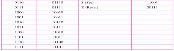


33 Substitution in 4B/5B block coding 8B/10B block encoding AMI used with scrambling Two cases of B8ZS scrambling technique


34 B8ZS substitutes eight consecutive zeros with 000VB0VB. Different situations in HDB3 scrambling technique HDB3 substitutes four consecutive zeros with 000V or B00V depending on the number of nonzero pulses after the last substitution. ANALOG-TO-DIGITAL CONVERSION A digital signal is superior to an analog signal. The tendency today is to change an analog signal to digital data. In this section we describe two techniques, pulse code modulation and delta modulation. PCM: The most common technique to change an analog signal to digital data (digitization) is called pulse code modulation (PCM). A PCM encoder has three processes. 1. The analog signal is sampled. 2. The sampled signal is quantized. 3. The quantized values are encoded as streams of bits. Components of PCM encoder The process of Pulse code modulation consists of the following steps: Sampling: measuring the amplitude of the signal at equal intervals.

35 Quantization: Process of assigning integral values in a specific range to the long range of sampled instances. Binary Coding: To bring into binary form Line Coding: conversion of binary data into digital signal. There are three sampling methods: ideal, natural, and flat-top. In ideal sampling, pulses from the analog signal are sampled. This is an ideal sampling method and cannot be easily implemented. In natural sampling, a high-speed switch is turned on for only the small period of time when the sampling occurs. The result is a sequence of samples that retains the shape of the analog signal. The most common sampling method, called sample and hold, however, creates flat-top samples by using a circuit. Nyquist sampling rate for low-pass and band-pass signals According to the Nyquist theorem, the sampling rate must be at least 2 times the highest frequency contained in the signal. TRANSMISSION MODES The transmission of binary data across a link can be accomplished in either parallel or serial mode. In parallel mode, multiple bits are sent with each clock tick. In serial mode, 1 bit is sent with each clock tick. While there is only one way to send parallel data, there are three subclasses of serial transmission: asynchronous, synchronous, and isochronous. Data transmission and modes


36 Parallel transmission The advantage of parallel transmission is speed. All else being equal, parallel transmission can increase the transfer speed by a factor of n over serial transmission. But there is a significant disadvantage: cost. Parallel transmission requires n communication lines (wires in the example) just to transmit the data stream. Because this is expensive, parallel transmission is usually limited to short distances. Serial transmission In serial transmission all the data bits are transmitted across a single wire in sequence. The advantage of serial over parallel transmission is that with only one communication channel, serial transmission reduces the cost of transmission over parallel by roughly a factor of n. Asynchronous transmission Asynchronous transmission is so named because the timing of a signal is unimportant. We send 1 start bit (0) at the beginning and 1 or more stop bits (1s) at the end of each byte.


37 There may be a gap between each byte. It is asynchronous at the byte level, bits are still synchronized; their durations are the same. The addition of stop and start bits and the insertion of gaps into the bit stream make asynchronous transmission slower than forms of transmission that can operate without the addition of control information. But it is cheap and effective, two advantages that make it an attractive choice for situations such as low-speed communication. Synchronous transmission In synchronous transmission, we send bits one after another without start or stop bits or gaps. It is the responsibility of the receiver to group the bits. Timing becomes very important, therefore, because the accuracy of the received information is completely dependent on the ability of the receiving device to keep an accurate count of the bits as they come in. The advantage of synchronous transmission is speed. With no extra bits or gaps, synchronous transmission is faster than asynchronous transmission. Isochronous In real-time audio and video, in which uneven delays between frames are not acceptable, synchronous transmission fails. For example, TV images are broadcast at the rate of 30 images per second; they must be viewed at the same rate. If each image is sent by using one or more frames, there should be no delays between frames. For this type of application, synchronization between characters is not enough; the entire stream of bits must be synchronized. The isochronous transmission guarantees that the data arrive at a fixed rate.
 performs the function of transporting the digital data in an analog waveform.")

38 Analog Transmission DIGITAL-TO-ANALOG CONVERSION Digital-to-Analog conversion is the process of changing one of the characteristics of an analog signal based on the information in digital data. Digital data needs to be carried on an analog signal. A carrier signal (frequency f c) performs the function of transporting the digital data in an analog waveform. The analog carrier signal is manipulated to uniquely identify the digital data being carried Types of digital-to-analog conversion Bit rate is the number of bits per second. Baud rate is the number of signal elements per second. In the analog transmission of digital data, the baud rate is less than or equal to the bit rate. Example An analog signal carries 4 bits per signal element. If 1000 signal elements are sent per second, find the bit rate. Solution In this case, r = 4, S = 1000, and N is unknown. We can find the value of N from Q. An analog signal has a bit rate of 8000 bps and a baud rate of 1000 baud. How many data elements are carried by each signal element? How many signal elements do we need? Solution S = 1000, N = 8000, and r and L are unknown. We find first the value of r and then the value of L. Amplitude Shift Keying (ASK) ASK is implemented by changing the amplitude of a carrier signal to reflect amplitude levels in the digital signal. For example: a digital 1 could not affect the signal, whereas a digital 0 would, by making it zero. The line encoding will determine the values of the analog waveform to reflect the digital data being carried.
S d is due to modulation and filtering, lies between 0 and 1.")

 is 2f,")
39 Bandwidth of ASK The bandwidth B of ASK is proportional to the signal rate S. B = (1+d)S d is due to modulation and filtering, lies between 0 and 1. Binary amplitude shift keying Frequency Shift Keying The digital data stream changes the frequency of the carrier signal, f c. For example, a 1 could be represented by f 1=f c +f, and a 0 could be represented by f 2=f c-f. Bandwidth of FSK If the difference between the two frequencies (f 1 and f 2) is 2f, then the required BW B will be: B = (1+d)xS +2f Binary frequency shift keying Phase Shift Keying
xS PSK is much more robust than ASK as it is not that vulnerable to noise, which changes amplitude of the signal.")
40 We vary the phase shift of the carrier signal to represent digital data. The bandwidth requirement, B is: B = (1+d)xS PSK is much more robust than ASK as it is not that vulnerable to noise, which changes amplitude of the signal. Binary phase shift keying Quadrature PSK To increase the bit rate, we can code 2 or more bits onto one signal element. In QPSK, we parallelize the bit stream so that every two incoming bits are split up and PSK a carrier frequency. One carrier frequency is phase shifted 90 o from the other - in Quadrature. The two PSKed signals are then added to produce one of 4 signal elements. L = 4 here. Quadrature amplitude modulation is a combination of ASK and PSK. Constellation Diagrams A constellation diagram helps us to define the amplitude and phase of a signal when we are using two carriers, one in quadrature of the other. The X-axis represents the in-phase carrier and the Y-axis represents quadrature carrier. Constellation diagrams for some QAMs ANALOG-TO-ANALOG CONVERSION Analog-to-analog conversion is the representation of analog information by an analog signal. One may ask why we need to modulate an analog signal; it is already analog. Modulation is needed if the medium is band-pass in nature or if only a band-pass channel is available to us.

b.")

41 Amplitude Modulation The total bandwidth required for AM can be determined from the bandwidth of the audio signal: B AM = 2B. Frequency Modulation The total bandwidth required for FM can be determined from the bandwidth of the audio signal: B FM = 2(1 + β)b. Phase Modulation The total bandwidth required for PM can be determined from the bandwidth and maximum amplitude of the modulating signal: B PM = 2(1 + β)b.
42 TELEPHONE MODEM MODEMS The term modem is a composite word that refers to the two functional entities that make up the device; a signal modulator and a signal demodulator. A modulator creates a band-pass analog signal from binary data. A demodulator recovers the binary data from the modulated signal. Modem stands for modulator and demodulator. TELEPHONE MODEMS Traditional telephone lines can carry frequencies between 300 and 3300 HZ, giving them BW of 3000 Hz; All this range is used for transmitting voice, where a great deal of interference and distortion can be accepted without loss of intelligibility. The effective BW of a telephone line being used for data Transmission is 2400 Hz, covering the range from 600 to 3000 Hz. Modem standards: V-series standards published by the ITU-T. V.32 V.32bis V.34bis V.90 V.92 V.32 This modem uses a combined modulation and demodulation encoding technique called trelliscoded modulation. Trellis is essentially QAM plus a redundant bit. The Data stream is divided into 4-bit sections. Instead of a quad bit, however, a pentabit is transmitted. The value of the extra bit is calculated from the values of the data bits. In any QAM system, the receiver compares each received signal point to all valid points in the constellation and selects the closest point as the intended value.. A signal distorted by transmission noise can arrive closer in value to an adjacent point than to the intended point, resulting in a misidentification of the point and an error in the received data. By adding a redundant bit to each quad bit, trellis-coded modulation increases the amount of information used to identify each bit pattern thereby reduces the number of possible matches. The V.32 calls for 32-QAM with a baud rate of Because only 4 bits of each pentabit represents data, the resulting speed is 4*2400=9600. FDX 2400 baud 9600 bps 2-wire Bandwidth diagram V.32 bis The V.32 bis modem support 14,400-bps transmission. The V.32 uses 128-QAM transmission.
43 V.34 bis The V.34 bis modem support 28,800-bps transmission with a 960-point constellation to a bit rate of 33,600 with a 1664-point constellation. V.90 Traditional modems have a limitations on the data rate.v.90 modems with a bit rate of 56,000 bps, called 56Kmodems, are available. Downloading rate is 56K, while the uploading rate is a maximum of 33.6 kbps. Traditional modems In traditional modems data exchange is between two computers, A and B, Through digital telephone network. Sampling & noise PCM Telephon e network Inverse PCM Modem A A to B Quantization noise happens in the Telco office near A Modem B After modulation by the modem, an analog signal reaches the telephone company Switching station. Where it is sampled and digitized to be passed through the digital network. The quantization noise introduced in the signal at the sampling point limits the data rate according to the capacity. This limit is 33.6 Kbps. 56K Modems Communication today is via the Internet. In Uploading, The analog signal must still be sampled at the switching station, which means the data rate in the uploading is limited to 33.6 Kbps. There is no sampling in downloading. Data rate in downloading is 56Kbps. V.92 The standard above V.92 is called V.92. These modems can adjust their speed, and if the noise allows, they can upload data at the rate of 48 Kbps. The modem has additional features. For example, the modem can interrupt the internet connection when there is an incoming call if the lines has callwaiting service.
 transmission of multiple signals across a single data link. As data and telecommunications use increases, so does traffic.")

, which separates the stream back into its component transmissions (one-to-many) and directs them to their corresponding lines.")
44 MULTIPLEXING Whenever the bandwidth of a medium linking two devices is greater than the bandwidth needs of the devices, the link can be shared. Multiplexing is the set of techniques that allows the (simultaneous) transmission of multiple signals across a single data link. As data and telecommunications use increases, so does traffic. There are three basic multiplexing techniques: frequency-division multiplexing, wavelength-division multiplexing, and time-division multiplexing. The first two are techniques designed for analog signals, the third, for digital signals. In a multiplexed system, n lines share the bandwidth of one link. The lines on the left direct their transmission streams to a multiplexer (MUX), which combines them into a single stream (many-toone). At the receiving end, that stream is fed into a demultiplexer (DEMUX), which separates the stream back into its component transmissions (one-to-many) and directs them to their corresponding lines. In the figure, the word link refers to the physical path. The word channel refers to the portion of a link that carries a transmission between a given pair of lines. One link can have many (n) channels. Frequency-division multiplexing (FDM): It is an analog technique that can be applied when the bandwidth of a link (in hertz) is greater than the combined bandwidths of the signals to be transmitted. In FDM, signals generated by each sending device modulate different carder frequencies. These modulated signals are then combined into a single composite signal that can be transported by the link. Carrier frequencies are separated by sufficient bandwidth to accommodate the modulated signal. These bandwidth ranges are the channels through which the various signals travel.

 is designed to use the high-data-rate capability of fiberoptic cable.")


45 Channels can be separated by strips of unused bandwidth guard bands to prevent signals from overlapping. FDM Process: The de-multiplexer uses a series of filters to decompose the multiplexed signal into its constituent component signals. The individual signals are then passed to a demodulator that separates them from their carriers and passes them to the output lines. Wavelength-division multiplexing (WDM) is designed to use the high-data-rate capability of fiberoptic cable. The optical fiber data rate is higher than the data rate of metallic transmission cable. Using a fiber-optic cable for one single line wastes the available bandwidth. Multiplexing allows us to combine several lines into one. WDM is an analog multiplexing technique to combine optical signals. The combining and splitting of light sources are easily handled by a prism. Using this technique, a multiplexer can be made to combine several input beams of light, each containing a narrow band of frequencies, into one output beam of a wider band of frequencies. A demultiplexer can also be made to reverse the process.

46 Time-Division Multiplexing: Time-division multiplexing (TDM) is a digital process that allows several connections to share the high bandwidth of a link. Instead of sharing a portion of the bandwidth as in FDM, time is shared. Each connection occupies a portion of time in the link. Note that the same link is used as in FDM; here, however, the link is shown sectioned by time rather than by frequency. In the figure, portions of signals 1, 2, 3, and 4 occupy the link sequentially. TDM is a digital multiplexing technique for combining several low-rate channels into one high-rate one. We can divide TDM into two different schemes: synchronous and statistical. In synchronous TDM, each input connection has an allotment in the output even if it is not sending data. In synchronous TDM, the data rate of the link is n times faster, and the unit duration is n times shorter. Interleaving The process of taking a group of bits from each input line for multiplexing is called interleaving. We interleave bits (1 - n) from each input onto one output. TDM can be visualized as two fast-rotating switches, one on the multiplexing side and the other on the demultiplexing side. The switches are synchronized and rotate at the same speed, but in opposite directions. On the multiplexing side, as the switch opens in front of a connection, that connection has the opportunity to send a unit onto the path. This process is called interleaving. Empty Slots Synchronous TDM is not as efficient as it could be. If a source does not have data to send, the corresponding slot in the output frame is empty. Data Rate Management: There are three strategies that can be used to overcome the data rate mismatch: multilevel, multislot and pulse stuffing Multilevel: used when the data rate of the input links are multiples of each other. Multislot: used when there is a GCD between the data rates. The higher bit rate channels are allocated more slots per frame, and the output frame rate is a multiple of each input link.
47 Pulse Stuffing Sometimes the bit rates of sources are not multiple integers of each other. Therefore, neither of the above two techniques can be applied. One solution is to make the highest input data rate the dominant data rate and then add dummy bits to the input lines with lower rates. This will increase their rates. This technique is called pulse stuffing, bit padding, or bit stuffing. Statistical Time-Division Multiplexing: As we saw in the previous section, in synchronous TDM, each input has a reserved slot in the output frame. This can be inefficient if some input lines have no data to send. In statistical time-division multiplexing, slots are dynamically allocated to improve bandwidth efficiency. Only when an input line has a slot's worth of data to send is it given a slot in the output frame. In statistical multiplexing, the number of slots in each frame is less than the number of input lines. The multiplexer checks each input line in round- robin fashion; it allocates a slot for an input line if the line has data to send; otherwise, it skips the line and checks the next line. Addressing: in statistical TDM, a slot needs to carry data as well as the address of the destination. In statistical multiplexing, there is no fixed relationship between the inputs and outputs because there are no preassigned or reserved slots. Slot Size Since a slot carries both data and an address in statistical TDM, the ratio of the data size to address size must be reasonable to make transmission efficient. No Synchronization Bit The frames in statistical TDM need not be synchronized, so we do not need synchronization bits. Bandwidth In statistical TDM, the capacity of the link is normally less than the sum of the capacities of each channel. The designers of statistical TDM define the capacity of the link based on the statistics of the load for each channel. If on average only x percent of the input slots are filled, the capacity of the link reflects this.

, each with its own plastic insulation, twisted together.")
48 Transmission Media A transmission media define as anything that can carry information from a source to a destination. Transmission media are actually located below the physical layer and directly controlled by the physical layer. Transmission media can be divided into two broad categories Guided Unguided Guided media Guided media, which are those that provide a conduit from one device to another, include twistedpair cable, coaxial cable, and fiber-optic cable. 1. Twisted-Pair Cable A twisted pair consists of two conductors (normally copper), each with its own plastic insulation, twisted together. One of the wires is used to carry signals to the receiver, and the other is used only as a ground reference. The receiver uses the difference between the two. In addition to the signal sent by the sender on one of the wires, interference (noise) and crosstalk may affect both wires and create unwanted signals. The most common twisted-pair cable used in communications is referred to as unshielded twistedpair (UTP). IBM has also produced a version of twisted-pair cable for its use called shielded twistedpair (STP). STP cable has a metal foil or braided- mesh covering that encases each pair of insulated conductors. Although metal casing improves the quality of cable by preventing the penetration of noise or crosstalk, it is bulkier and more expensive. Connector: Registered Jack (RJ 45) Applications Twisted-pair cables are used in telephone lines to provide voice and data channels. 2. Coaxial Cable Coaxial cable (or coax) carries signals of higher frequency ranges than those in twisted- pair cable, in part because the two media are constructed quite differently. Instead of having two wires, coax has a central core conductor of solid or stranded wire (usually copper) enclosed in an insulating sheath, which is, in turn, encased in an outer conductor of metal foil, braid, or a combination of the two. The outer metallic wrapping serves both as a shield against noise and as the second conductor completing the circuit. This outer conductor is also enclosed in an insulating sheath, and the whole cable is protected by a plastic cover

49 Coaxial cable Standards Coaxial cables are categorized by their radio government (RG) ratings.each RG number denotes a set of physical specifications such as, wire gauge of the inner conductor thickness and type of the inner insulator the construction of the shield the size and type of outer casing Categories of coaxial cables Category Impedance Use RG-59 75Ω Cable TV RG-58 50Ω Thin Ethernet RG-11 50Ω Thick ethernet Coaxial Cable Connectors Coaxial Cable Connectors are used to connect coaxial cable to devices. The most common type of connector is the Bayone Neill-concelman or BNC connectors. There are three popular types of connectors BNC connector BNC T connector & BNC terminator BNC connector It is used to connect the end of the cable to a device such as a TV set. BNC T connector It is used in Ethernet networks to branch out a cable for connection to a computer or other devices. BNC terminator It is used at the end of the cable to prevent the reflection of the signal. Performance Applications Attenuation is much higher in coaxial cables than in twisted pair cable. Coaxial cable has a much higher bandwidth the signal weakens rapidly and needs the frequent use of repeaters. Coaxial cable is used in analog telephone network where a single coaxial cable could carry 10,000 voice signals. It is also used in digital telephone network where a cable could carry digital data up to 600 Mbps. Cable TV networks also used RG-59 coaxial cables. It is also used in traditional Ethernets. Fiber Optic Cable. A fiber optic cable is made of glass or plastic and transmits signals in the form of light. Optical fibers use reflection to guide light through a channel. A glass or plastic core is surrounded by a cladding of less dense glass or plastic. The difference in the density of the two materials must be such that a beam of light moving through the core is reflected off the cladding.
50 Propagation Modes There are two modes for propagating light along optical channels; each requires fiber with different physical characteristics Multimode Single mode Multimode Multiple beams from a light source move through the core in different paths. Multimode can be implemented in two forms Step-index Graded index Multimode Step index fiber In Multimode Step index fiber the density of the fiber remains constant from the center to the edges A beam of light moves through this constant density in a straight line. When it reaches the interface of the core and the cladding, there is an abrupt change to a lower density that alters the angle of the beams motion. Step-index -> the suddenness of this change. Multimode Graded-index fiber It decreases the distortion of the signal through the cable. Density is highest at the center of the core and decreases gradually to its lowest at the edge. Single-Mode It uses step-index fiber and a highly focused source of light that limits beams to a small range of angles, all close to the horizontal The Single-Mode fiber itself is manufactured with a smaller diameter than that of multimode fiber and with lower density. This results in a critical angle that is close enough to 90. to make it horizontal. All the beams arrive at the destination together and can be recombined with little distortion to the signal. Fiber Sizes Optical fibers are defined by the ratio of the diameter of their core to the diameter of their cladding expressed in micrometers. Fiber-optic cable connectors. Three different types of connectors are used by fiber optic cable. SC (subscriber channel) Connector: It is used in cable TV. ST (Straight-tip) Connector: It is used for connecting cable to networking devices. Performance: Attenuation is flatter than in the case of twisted pair cable and coaxial cable. Few repeaters are needed when we use fiber optic cable. Application It is used in cable TV and LAN (Fast Ethernet and 100Base X. Advantages Higher bandwidth: It can support higher bandwidth than twisted pair or coaxial cable. Less signal attenuation: Transmission distance is greater than that of other guided media. Signals can be transmitted for 50 km without requiring regeneration.

51 Immunity to electromagnetic Interference: Electromagnetic noise can not affect fiber-optic cables Resistance to corrosive materials: glass is more resistant to corrosive materials. Light-weight: It is of less weight than the copper cables. More Immune to taping: Fiber-optic cables are more immune to taping than copper cables. Disadvantages: Installation/Maintenance. Installation/Maintenance need expertise since it is a new technology. Unidirectional: Propagation of light is unidirectional. Bidirectional communication is achieved by means of two optical fibers. Cost: It is more expensive and the use of optical fiber cannot be justified if the need for bandwidth is not high. UNGUIDED MEDIA: WIRELESS Unguided media transport electromagnetic waves without using a physical conductor. This type of communication is often referred to as wireless communication. Unguided signal can travel from the source to destination in several ways: 1. Ground Propagation: Radio waves travel through the lowest portion of the atmosphere, hugging the earth. The low frequency signal follows the curvature of the planet. Distance depends on the amount of the power. 2. Sky Propagation: Higher frequency radio radiate upward into the ionosphere where they are reflected back to the earth. Sky propagation allow for greater distance with lower power output. 3. line-of-sight Propagation: Very high frequency signals are transmitted in straight lines directly from antenna to antenna. Radio Waves: Radio Waves: Between 3 KHz 1 GHz. Radio waves use omnidirectional antenna. Radio waves used for multicast communication, such as radio and television. Sky Propagation. This makes radio waves a good candidate for long-distance broadcasting such as AM radio. Micro Waves: 1. Microwave propagation is line-of-sight. Since the towers with the mounted antennas need to be in direct sight of each other, towers that are far apart need to be very tall. 2. Very high-frequency microwaves cannot penetrate walls. This characteristic can be a disadvantage if receivers are inside buildings.
52 3. The microwave band is relatively wide, almost 299 GHz. Therefore wider subbandscan be assigned, and a high data rate is possible Use of certain portions of the band requires permission from authorities. Infrared waves: Between 300 GHz-400 THz Used for short-range communication. Very common with remote control devices, but can also be used for device-to-device transfers, such as PDA to computer. Line-of-sight propagation.


53 CIRCUIT SWITCHING AND TELEPHONE NETWORK Introduction: None of the previous works in larger networks with large physical separation or consisting of a large number of computers The solution is a switching network. Consists of a series of interlinked nodes called switches. Switches are capable to create temporary connections between two or more devices Circuit Switching: A circuit-switched network consists of a set of switches connected by physical links. A connection between two stations is a dedicated path made of one or more links each connection uses only one dedicated channel on each link Each link is normally divided into n channels by using FDM or TDM. The link can be permanent (leased line) or temporary (telephone) A circuit switch is a device with n inputs and m outputs that creates a temporary connection between an input link and an output link. The number of inputs does not have to match the number of outputs. The common categories of switch are: 1. Space division Switch 2. Time division switch
54 Space division switch: Developed for analog environment, but has been carried over into digital communication Requires separate physical paths for each signal connection Uses metallic or semiconductor gates Its basic device is the Crossbar switch Number of crosspoints grows as square of number of stations Loss of crosspoint prevents connection Inefficient use of crosspoints All stations connected, only a few crosspoints in use Non-blocking paths in the circuit are separated from each other spatially. Crossbar Switch Crossbar switch connects n inputs to m outputs in a grid, using electronic microswitches (transistors) at each cross-point. Limitation is the number of cross-points required. Advantages: simple to implement simple control strict sense non-blocking Multicast Single source multiple destination ports Drawbacks number of crosspoints, N 2 large VLSI space vulnerable to single faults Multistage switch: Multistage switch combines crossbar switches in several stages. Design of a multistage switch depends on the number of stages and the number of switches required (or desired) in each stage. Normally, the middle stages have fewer switches than do the first and last stages.

 TSI consists of random access memory (RAM) with several memory locations.")
55 Multiple paths are available in multistage switches. Blocking refers to times when two inputs are looking for the same output. The output port is blocked. Time-Division Switch Time-division switching uses time-division multiplexing to achieve switching. Two methods used are: Time-slot interchange (TSI) changes the order of the slots based on the desired connection. TDM bus FIG: Time-division multiplexing, without and with a time-slot interchange Time Slot Interchange (TSI) TSI consists of random access memory (RAM) with several memory locations. The size of each location is the same as the size of a single time slot. The number of locations is the same as the number of inputs. The RAM fills up with incoming data from time slots in the order received. Slots are then sent out in an order based on the decisions of a control unit.


56 TDM bus Input and output lines are connected to a high-speed bus through input and output gates (microswitches) Each input gate is closed during one of the four slots. During the same time slot, only one output gate is also closed. This pair of gates allows a burst of data to be transferred from one specific input line to one specific output line using the bus. The control unit opens and closes the gates according to switching need. Comparison of SDM and TDM SDM o Advantage: Instantaneous. o TDM o o Disadvantage: Number of cross points required. Advantage: No cross points. Disadvantage: Processing delay.
, time-space-space-time (TSST), space-timetime-space (STTS), etc. TELEPHONE NETWORK: Telephone networks use circuit switching.")

57 TST switch Combine Space division and time division switching. This results in switches that are optimized both physically (the number of crosspoints) and temporally (the amount of delay). Various types are: time-space-time (TST), time-space-space-time (TSST), space-timetime-space (STTS), etc. TELEPHONE NETWORK: Telephone networks use circuit switching. In 1800s, Plain old telephone system (POTS) was an analog system using analog signals to transmit voice. In 1980s, POTS started carrying data along with voice and also has become digital instead of analog. Major components of Telephone network: Local loops, trunk, and switching office. Different levels of switching offices: End offices, tandem offices, and regional offices. Local loop: Twisted pair cable that connects the subscriber telephone to the nearest end office or local central office. It has a bandwidth of 4000 Hz for voice. The first three digits of local telephone number define the office, and the next four digits define the local loop number. Trunks: Transmission media that handle communication between offices. It handles hundreds or thousands of connections through multiplexing. Transmission is usually through optical fibers or satellite links. Switching office: To avoid having a permanent physical link between any two subscribers, switches are located here. Switch connects several local loops or trunks and allows different subscribers to connect. Fig: A Telephone Network LATA (Local access transport areas) Services offered by the common carriers (telephone companies) inside a LATA are called intra- LATA services. The carrier that handles these services is called a local exchange carrier (LEC).
 and competitive local exchange carriers (CLEC) ILEC would provide main services and owns the local loop.")
58 Intra-LATA services are provided by local exchange carriers. Since 1996, there are two types of LECs: incumbent local exchange carriers (ILEC) and competitive local exchange carriers (CLEC) ILEC would provide main services and owns the local loop. CLEC would provide other services such as mobile telephone service, toll calls inside a LATA, Communication inside a LATA is handled by end switches and tandem switches. A call that can be completed by using only end offices is called toll-free. A call that has to go through a tandem office (intra-lata toll office) is charged. Fig. Switching offices in a LATA Interexchange carriers (IXCs) or long-distance companies handle services between LATAs. Carriers that provide inter-latas include AT&t, MCI, WorldCom. A telephone call going through an IXC is normally digitized, with the carriers using several types of networks to provide service. Intra-LATA services can be provided by several LECs (one ILEC and possibly more than one CLEC). Point of Presence (POP) is a switching office. Each IXC that wants to provide inter-lata services in a LATA must have a POP in that LATA. Fig: POPs Making a Connection: Accessing the switching station at the end offices is accomplished through dialing. In the past, telephones featured rotary or pulse dialing, in which a digital signal was sent to the end office for each number dialed. This type of dialing was prone to errors due to the inconsistency of humans during the dialing process. Today, dialing is accomplished through the touch-tone technique. In this method, instead of sending a digital signal, the user sends two small bursts of analog signals, called dual tone. The frequency of the signals sent depends on the row and column of the pressed pad. Pressing number 8 will generate two bursts of analog signals with frequencies 852 and 1336 Hz to the end office. Analog Services [Analog Switches Service]
59 Local loop is analog; bandwidth is usually between 0 and 4000 Hz. With switched lines, when the caller dials a number, the call is conveyed to a switch, or series of switches, at the exchange. The appropriate switches are then activated to link the caller s line to that of the person being called. The switch connects the two lines for the duration of the call. Local Call services: Flat monthly rate OR rate for each call or a set of calls. Toll Call services: Toll call can be intra-lata or inter-lata. Inter-LATA calls are long distance calls [that pass via a tandem office (toll office)] and are charged for. 800 Services: If a subscriber (normally an organization) needs to provide free connections for other subscribers (normally customers), it can request an 800 service [also 888, 877, 866]. Call is free for caller but it is paid by the callee. Rate is less expensive than a normal long distance call. WATS: Wide-Area Telephone Service It is the opposite of 800/888 service. Charged for outbound calls. Service is a less expensive alternative to regular toll calls; charges are based on number of calls. Service can be specified as outbound calls to the same state, to several states, or to the whole country, with rates charged accordingly. 900 Services: Call is paid by the caller and is normally much more expensive than a normal longdistance call. The reason is that the carrier charges two fees; the first is the long-distance toll, and the second is the fee paid to the callee for each call. This service is used by organization that needs to charge customers for its services. Analog Leased Services Offers customers the opportunity to lease a line, sometimes called a dedicated line, that is permanently connected to another customer. Although the connection still passes through the switches in the telephone network, subscribers experience it as a single line because the switch is always closed, no dialing is needed. Digital Services Digital Services are less sensitive than analog services to noise and other forms of interference. Common digital services are switched/56 and digital data service (DDS). Switched/56 Service Digital version of an analog switched line. It is a switched digital service that allows data rates of up to 56 Kbps. To communicate through this service, both parties must subscribe. A caller with normal telephone service cannot connect to a telephone or computer with switched/56 even if using a modem. On the whole, digital and analog services represent two completely different domains for the telephone companies. Switched/56 service is digital and so subscribers do not need modems to transmit digital data. However, the do need another device called a digital service unit (DSU). This device provides 56 Kbps and encodes the digital data in the format used by service provider. Supports bandwidth on demand, video conferencing, fast facsimile, multimedia, fast data transfer, etc. Also allows subscribers to obtain higher speeds by using more than one line (inverse multiplexing). Digital Data Service
60 Digital version of an analog leased line; it is a digital leased line with a maximum data rate of 64 Kbps. Telephone history Before 1984 Local and long-distance services were provided by AT&T Bell System. By law, this monopoly company was broken into AT&T Long lines, 23 Bell Operating Companies (BOCs) and others. Telephone rates became lower after this law. Between 1984 and 1996 LATAs and IXCs were formed. No LEC provide long-distance services and no IXC provide local services. After 1996 A common carrier company provides both inside the LATA and between LATA services. To avoid recabling of residents, the carrier that was given intra-lata services (ILEC) continues to provide the main services; the new competitors (CLEC) provide other services.


61 ERROR DETECTION AND CORRECTION ERROR: Data can be corrupted during transmission. For reliable communication, errors must be detected and corrected. TYPES OF ERRORS: Single bit Error: The term single bit error means that only one bit of a given data unit is changed from 1 to 0 or 0 to is changed to here only one bit is changed by single bit error. Burst Error: A burst error means that 2 or more bits in the data unit have changed. Example: Here two bits are corrupted. Redundancy Error detection use the concept of redundancy, which means adding extra bits for detecting errors at the destination.i.e., instead of repeating the entire data stream, a shorter group of bits may be appended to the end of each unit. Detection methods

62 Parity check Cyclic redundancy check checksum Parity check A redundant bit called parity bit is added to every data unit so that the total number of 1 s in the unit becomes even (or odd). SIMPLE PARITY CHECK In a simple parity check a redundant bit is added to a string of data so that total number of 1 s in the data become even or odd. The total data bit is then passed through parity checking function. For even parity, it checks for even number of 1 s and for odd parity it checks even number of 1 s. If an error is detected the data is rejected. Example 1: data to be transmitted = s in the data Parity bit is 1 to make even Transmitted codeword = If receiver gets , parity check ok ---accept (OK) If receiver gets , parity check fails ---reject (OK), ask for frame to be re-transmitted If receiver gets , parity check ok ---accept (NOT OK: even number of errors undetected) If receiver gets , parity check ok ---accept (NOT OK: even number of errors undetected) Example 2: data to be transmitted = s in the data parity bit is 0

63 Transmitted codeword = Dimensional Parity Check: Form data into a 2-dimensional array; add single parity check bits to each row and each column; transmit row-by-row Example: data = Form 3 7 array and add row and column parity bits: Data bits row parity bits Column parity bits transmitted: Receiver knows to form received bit string into 4 8 array, then check the row and column parity bits Can detect any odd number of bit errors in a row or column, and can detect an even number of bit errors if they re in a single row (using the column parity checks) or in a single column (using the row parity checks); and can correct any single bit error Example (cont.): suppose bit in position (1,3) is received in error (in other words, 1 bit error) row 1 parity check fails row 2 parity check ok row 3 parity check ok row 4 parity check ok column 1 parity check fails column 2 parity check ok column 3 parity check fails column 4 parity check ok column 5 parity check ok column 6 parity check ok column 7 parity check ok
 CYCLIC REDUNDANCY CHECK CRC is based on binary division.")

64 column 8 parity check ok Therefore the receiver can detect that bit errors Occurred, but it cannot Correct them (here, if the Bit errors were in positions (1,3) and (2,1) instead, the receiver parity checks would be the same) CYCLIC REDUNDANCY CHECK CRC is based on binary division. In CRC, instead of adding bits to achieve the desired parity, a sequence of redundant bits, called the CRC or the CRC remainder, is appended to the end of the data unit so that the resulting data unit becomes exactly divisible by a second, predetermined binary number. At its destination, the incoming data unit is assumed to be intact and is therefore accepted. A remainder indicates that the data unit has been damaged in transit and therefore must be rejected. CRC GENERATOR:


65 CRC CHECKER: POLYNOMIALS The divisor in the CRC most often represented not as a string of 1s and 0s, but as an algebraic polynomial. The polynomial format is useful to solve the concept mathematically. Standard Polynomials:
 To create the checksum the sender does the following: The unit is divided into K sections, each of n bits. Section 1 and 2 are added together using one s complement.")
66 Checksum: ~ used by the higher layer protocols ~ is based on the concept of redundancy (VRC, LRC, CRC.) To create the checksum the sender does the following: The unit is divided into K sections, each of n bits. Section 1 and 2 are added together using one s complement. Section 3 is added to the result of the previous step. Section 4 is added to the result of the previous step. The process repeats until section k is added to the result of the previous step. The final result is complemented to make the checksum. At Sender: Original data: Sum Checksum At Receiver: Received data: Sum Complement Error Correction (Hamming Encoding Algorithm): Redundancy Bits To calculate the number of redundancy bits (R) required to correct a given number of data bit (M) If the total number of bits in a transmittable unit is m+r, then r must be able to indicate at least m+r+1 different states 2 r m + r + 1 ex) For value of m is 7(ASCII), the smallest r value that can satisfy this equation is positions of redundancy bits in Hamming code: each r bit is the VRC bit for one combination of data bits r 1 = bits 1, 3, 5, 7, 9, 11 r 2 = bits 2, 3, 6, 7, 10, 11 r 4 = bits 4, 5, 6, 7 r 8 = bits 8, 9, 10, 11


67 Error Detection and Correction: Error detection using Hamming Code
68 FLOW CONTROL AND ERROR CONTROL The two main features of data kink layer are flow control and error control..flow CONTROL Flow control coordinates that amount of data that can be sent before receiving ACK It is one of the most important duties of the data link layer. ERROR CONTROL Error control in the data link layer is based on ARQ (automatic repeat request), which is the retransmission of data. The term error control refers to methods of error detection and retransmission. Anytime an error is detected in an exchange, specified frames are retransmitted. This process is called ARQ. FLOW AND ERROR CONTROL MECHANISMS 1. STOP-AND WAIT ARQ. 2. GO-BACK-N ARQ. 3. SELECTIVE-REPEAT ARQ. STOP-AND- WAIT ARQ This is the simplest flow and error control mechanism. It has the following features. The sending devise keeps the copy of the last frame transmitted until it receives an acknowledgement for that frame. Keeping a copy allows the sender to re- transmit lost or damaged frames until they are received correctly. Both data and acknowledgement frames are numbered alternately 0 and 1. A data frame 0 is acknowledged by an ACK 1. A damaged or lost frame is treated in the same manner by the receiver. If the receiver detects an error in the received frame, it simply discards the frame and sends no acknowledgement. The sender has a control variable, which we call S, that holds the number of recently sent frame. The receiver has a control variable, which we call R that holds the number of the next frame expected. The sender starts a timer when it sends a frame. If an ACK is not received within an allotted time period the sender assumes that the frame was lost or damaged and resends it. The receivers send only positive ACK for frames received safe and sound; it is silent about the frames damaged or lost. OPERATION: The possible operations are Normal operation lost frame ACK lost delayed ACK. The sender sends frame 0 and wait to receive ACK 1. when ACK 1 is received it sends frame 1 and then waits to receive ACK 0, and so on. The ACK must be received before the time out that is set expires. The following figure shows successful frame transmission.
69 Sender Receive r S=0 Frame 0 ACK 1 S=1 Frame 1 S=0 ACK 0 R=0 R=1 Time Time Lost or damaged acknowledgement o When the receiver receives the damaged frame it discards it, which essentially means the frame is lost. The receiver remains silent about a lost frame and keeps its value of R. o For example in the following figure the sender transmits frame 1, but it is lost. The receiver does nothing, retaining the value of R (1). After the timer at the sender site expires, another copy of frame 1 is sent. Sender Receive r Time-out S=0 Frame 0 R=0 ACK 1 S=1 Frame 1 R=1 Lost S=1 Frame 1 R=1 S=0 ACK0 R=0 Lost acknowledgement o A lost or damaged ACK is handled in the same by the sender; if the sender receives a damaged ACK, it discards it. o The following figure shows a lost ACK 0.the waiting sender does not know if frame 1 has been received. When the timer for frame 1 expires the sender retransmits frame 1.
70 o Note that the receiver has already received frame 1 and is expecting to receive frame 0. Therefore, its silently discards the second copy of frame 1. o The following figure shows a lost ACK 0.the waiting sender does not know if frame 1 has been received. When the timer for frame 1 expires the sender retransmits frame 1. o Note that the receiver has already received frame 1 and is expecting to receive frame 0. Therefore, its silently discards the second copy of frame 1. Sender Receive r S=0 Frame 0 ACK 1 S=1 Frame 1 Time-out S=1 Lost S=0 ACK 0 Frame 1 ACK0 R=0 R=1 R=0 Expecting frame 0 Frame 1 is discarded Delayed acknowledgement Time Time o An ACK can be delayed at the receiver or by some problem with the link. The following figure shows the delay of ACK 1; it ids received after the timer for frame 0 as already expired. o The sender has already retransmitted a copy of frame 0. The receiver expects frame 1 so its simply discards the duplicate frame 0. o The sender has now received two ACK s, one that was delayed and one that was sent after the duplicate frame 0 arrived. The second ACK 1 is discarded. Sender Receive r
71 Time-out S=0 Frame 0 R=0 ACK1 S=0 Frame0 R=1 S=1 Frame 1 ACK1 Discarded Expecting frame 0 Frame 1 is discarded S=1 Frame1 Time-out R=1 ACK0 Time Time BIDIRECTIONAL TRANSMISSION The stop and wait mechanism is unidirectional. We can have bi-directional transmission if the two parties have two separate channels for full duplex communication or share the same channel for off duplex transmission. In this case, each party needs both S and R variables to track frames sent and expected. PIGGYBACKING It s a method to combine a data frame with an ACK. In following figure both the sender and the receiver have data to send. Instead of sending separate data and ACK frames. It can save bandwidth because the overhead from a data frame and an ACK frame can be combined into just one frame. Sender Receive r R=0 S=0 Frame 0,ACK0 R=0 S=0 R=0 Frame0,ACK 1 S=1 Frame 1,ACK1 R=1 S=1 R=1 Frame1,ACK 0 S=0 Time Time

72 GO-BACK-N ARQ As in Stop-and-wait protocol senders has to wait for every ACK then next frame is transmitted. But in GO-BACK-N ARQ number of frames can be transmitted without waiting for ACK. A copy of each transmitted frame is maintained until the respective ACK is received. Features of GO-BACK-N ARQ 1.sequence numbers. Sequence numbers of transmitted frames are maintained in the header of frame. If k is the number of bits for sequence number, then the numbering can range from 0 to 2k-1. Example: if k=3 means sequence numbers are 0 to sender sliding window: Window is a set of frames in a buffer waiting for ACK. This window keeps on sliding in forward direction, the window size is fixed. As the ACK is received, the respective frame goes out of window and new frame to sent come into window. Figure illustrates the sliding window. If Sender receives. ACK 4, then it knows Frames upto and including Frame 3 were correctly received Window size=7 3. Receiver sliding window: In the receiver side size of the window is always one. The receiver is expecting to arrive frame in specifies sequence. Any other frame is received which is out of order is discarded. The receiver slides over after receiving the expected frame. The following figure shows the receiver side-sliding window Control variables: Sender variables and Receiver variables: Sender deals with three different variables S -> sequence number of recently sent frame SF -> sequence number of first frame in the window. SL -> sequence number of last frame in the window. The receiver deals with only one variable
73 R -> sequence number of frame expected. 5. Timers The sender has a timer for each transmitted frame. The receivers don t have any timer. 6. Acknowledgement: The receiver responds for frame arriving safely by positive ACK. For damaged or lost frames receiver doesn t reply, the sender has to retransmit it when timer of that frame elapsed. The receiver may ACK once for several frames. 7. resending frames: If the timer for any frame expires, the sender has to resend that frame and the subsequent frame also, hence the protocol is called GO-BACK-N ARQ. Operation Normal operation: Following diagram shows this mechanism. The sender keeps track of the outstanding frames and updates the variables and windows as acknowledgements arrive. SF SL Sender Receive r Frame S Frame ACK 2 S Frame ACK3 S Frame S Time Time Damaged or lost frame: Figure shows that frame 2 is lost. Note that when the receiver receives frame 3, it is discarded because the receiver is expecting frame 2, not frame3. after the timer for frame 2 expires at the sender site, the sender sends frame 2 and 3.
74 SF SL Sender Receive r Frame S Frame ACK 2 S Frame 2 lost Timeout resent Frame 3 resent Frame 2 Frame 3 Frame 3 is discarded, not in the window S R Time Time Damaged or lost acknowledgement: If an ACK is lost, we can have two situations. If the next ACK arrives before the expiration of timer, there is no need for retransmission of frames because ACK are cumulative in this protocol.. if the next ACK arrives after the timeout, the frame and all the frames after that are resent. The receiver never resends an ACK. For diagrams refer your class work notes. Delayed Acknowledgement: A delayed ACK also triggers the resending of frames. SELECTIVE REPEAT ARQ: The configuration and its control variables for this are same as those selective repeat ARQ. The size of the window should be one half of the value 2 m. The receiver window size must also be the size. In this the receiver is looking for a range of sequence numbers. The receiver has control variables RF and RL to denote the boundaries of the window.

 3 types of")

75 selective repeat also defines a negative ACK NAK that reports the sequence number of a damaged frame before the timer expires. High-level Data Link Control (HDLC) protocol HDLC standardized ISO in 1979 and accepted by most other standards bodies (ITU-T, ANSI) 3 types of end-stations: Primary sends commands Secondary can only responds to Primary s commands Combined can both command and respond 3 types of configuration (Note: no balanced multipoint)
 unbalanced config, secondary may initiate transmit without permission from primary, rarely used FRAMES: 3")
 FRAME FORMAT Flag Fields: Delimit frame at")
76 TRANSFER MODE Normal Response Mode (NRM) unbalanced config, primary initiates transfer used on multi-drop lines, eg host + terminals Asynchronous Balanced Mode (ABM) balanced config, either station initiates transmission, has no polling overhead, widely used Asynchronous Response Mode (ARM) unbalanced config, secondary may initiate transmit without permission from primary, rarely used FRAMES: 3 types of Frames are I-Frame transports user data and control info about user data. S-Frame supervisory Frame, only used for transporting control information U-Frame unnumbered Frame, reserved for system management(managing the link itself) FRAME FORMAT Flag Fields: Delimit frame at both ends Receiver hunts for flag sequence to synchronize Bit stuffing used to avoid confusion with data containing The transmitter inserts 0 bit after every sequence of five 1s with the exception of flag fields If receiver detects five 1s it checks next bit If 0, it is deleted If 1 and seventh bit is 0 (i.e., 10), accept as flag If sixth and seventh bits 1 (i.e., 11), sender is indicating abort
 Flow and error control piggybacked on information")
 response from peer in response frame is F bit set to 1 to indicate response to soliciting command seq number usually 3 bits can extend to 8 bits as")
77 Address Field: identifies secondary station that sent or will receive frame usually 8 bits long may be extended to multiples of 7 bits LSB indicates if is the last octet (1) or not (0) all ones address is broadcast Control Field: different for different frame type Information - data transmitted to user (next layer up) Flow and error control piggybacked on information frames Supervisory - ARQ when piggyback not used Unnumbered - supplementary link control first 1-2 bits of control field identify frame type use of Poll/Final bit depends on context in command frame is P bit set to1 to solicit (poll) response from peer in response frame is F bit set to 1 to indicate response to soliciting command seq number usually 3 bits can extend to 8 bits as shown below
 used for error detection either 16 bit CRC or 32 bit CRC Poll/Final Bit Use depends on context Command frame P")
 P/ F")
78 Information & FCS Fields: Information Field in information and some unnumbered frames must contain integral number of octets variable length Frame Check Sequence Field (FCS) used for error detection either 16 bit CRC or 32 bit CRC Poll/Final Bit Use depends on context Command frame P bit : used for poll from primary 1 to solicit (poll) response from peer Response frame F bit : used for response from secondary 1 indicates response to soliciting command I-Frames: Contains the sequence number of transmitted frames and a piggybacked ACK N(S) P/ F N(R) U-Frames:
79 Used for flow and error control S P/ F P/F: RR --- receive ready RNR --- receive not ready REJ --- reject on frame N(R) SREJ --- selective reject on N(R) N(R) S-Frames: S-frames are similar to unnumbered frames, the main difference being that they do carry sequence information. Some supervisory frames function as positive and negative acknowledgements, they therefore play a very important role in error and flow control. Two bits indicate the frame type, so that there are four possibilities. Receiver Ready -RR(Positive Acknowledgement) Receiver Not Ready -RNR Reject -REJ(NAK go-back-n) Selective Reject -SREJ(NAK selective retransmit) HDLC Operation Initialization: S-frames specify mode and sequence numbers, U-frames acknowledge Data Transfer: I-frames exchange user data, S-frames acknowledge and provide flow/error control Disconnect: U-frames initiate and acknowledge

80 PPP Point-to Point Protocol In a network, two devices can be connected by a dedicated link or a shared link. In the first case, the link can be used by the two devices at any time. We refer to this type of access as point-to-point access. In the second case, the link is shared between pairs of devices that need to use the link. We refer to this type of access as multiple access. One of the most common protocols for point-to-point access is the Point-to-Point Protocol (PPP). PPP services It defines the format of the frame to be exchanged between devices. It defines how two devices can negotiate the establishment of the link and the exchanged of data. It defines how network layer data are encapsulated in the data link frame. It defines how two devices can authenticate each other. PPP FRAME FORMAT Flag field. The flag fields identify the boundaries of a PPP frame. Its value is Address field. Because PPP is used for a point-to-point connection, it uses the broadcast address of HDCL, , to avoid a data link address in the protocol. Control field. The control field uses the format of the U-frame in HDCL. See pages Protocol field. The protocol field defines what is being carried in the data field: user data or other information. Data field. This field carries either the user data or other information. Frame check sequence (FCS) field. This field is used for error detection. Transition states A PPP connection goes through different phases called transition sates.


81 Idle state. The idle state means that the link is not being used. There is no active carrier, and the line is quiet. Establishing link. When one of the end point starts the communication, the connection goes into the establishing state. In this state, options are negotiated between the two parties. If the negotiation is successful, the system goes to the authenticating state (if authentication is required) or directly to the networking state. Authenticating state. The authenticating state is optional. If the result is successful, the connection goes to the networking state; otherwise, it goes to the terminating state. Networking State. When a connection reaches this state, the exchange of user control and data packets can be started. The connection remains in this state until one of the endpoints wants to terminate the connection. Terminating state. When the connection is in the terminating state, several packets are exchanged between the two ends for house cleaning and closing the link. PPP Stack Three sets of protocols are used by PPP: Link control protocol, authentication protocols, and network control protocol. Link Control Protocol (LCP) It is responsible for establishing, maintaining, configuring, and terminating links. It also provides negotiation mechanisms to set options between endpoints. Both endpoints of the link must reach an agreement about the options before the link can be established. When PPP is carrying an LCP packet, it is either in the establishing state or in the terminating state. All LCP packets are carried in the data field of the PPP frame. What defines the frame as one carrying an LCP packet is the value of the protocol field, which is set to C021 (base 16). LCP packet encapsulated in a frame


82 Link Control Protocol (LCP) Code. This field defines the type of LCP packet. ID. This field holds a value used to match a request with reply. One endpoint inserts a value in this field, which will be copied in the reply packet. Length. This field defines the length of the entire LCP packet. Information. This field contains extra information needed for some LCP packets. Configuration packets are used to negotiate the options between the two ends. There are four different types of packets for this purpose: configure-request, configure-ack, configure-nak, and configure-reject. Link termination packets. The link termination packets are used to disconnect the link between two endpoints. There are two types: terminate-request and terminate-ack. Link monitoring and debugging packets. These packets are used for monitoring and debugging the link. There are five types: code-reject, protocol-reject, echo-reply, discard-request. Authentication Protocols Authentication plays a very important role in PPP because PPP is designed for use over dial-up links where verification of user identity is necessary. Authentication means validating the identity of a user who needs to access a set of resources. PPP uses two protocols for authentication: Password Authentication Protocol (PAP) and Challenge Handshake Authentication Protocol (CHAP) PAP The PAP is a simple authentication procedure with two steps: 1. The user who wants to access a system sends an ID (identification) and a password. 2. The system checks the validity of the identification and password and either accepts or denies a connection. For those systems that require greater security, PAP is not enough. A third party with access to the link can easily pick up the password and access the system resources. PAP Packets:


83 CHAP Steps The CHAP protocol is a three-way handshaking authentication protocol that provides greater security than PAP. In this method, the password is kept secret; it is never sent on-line. The system sends to the user a challenge packet containing a challenge value, usually a few bytes. The user applies a predefined function that takes the challenge value and the user s own password and creates a result. The user sends the result in the response packet to the system. The system does the same. It applies the same function to the password of the user and the challenge value to create a result. If the result created is the same as the result sent in the response packet, access is granted; otherwise, it is denied. CHAP Packets: Network Control Protocol (NCP)

 Protocols: No station is superior to another station and none is assigned the control over another.")
84 After the link is established and authentication (if any) is successful, the connection goes on the networking state. NCP is a set of control protocols to allow the encapsulation of data coming from network layer protocols into the PPP frame. The set of packets that establish and terminate a network layer connection is called Internetwork Protocol Control Protocol (IPCP). IPCP packet encapsulated in PPP frame Multiple Access RANDOM ACCESS: Random Access (or contention) Protocols: No station is superior to another station and none is assigned the control over another. A station with a frame to be transmitted can use the link directly based on a procedure defined by the protocol to make a decision on whether or not to send. ALOHA Protocols Was designed for wireless LAN and can be used for any shared medium Pure ALOHA Protocol Description All frames from any station are of fixed length (L bits) Stations transmit at equal transmission time (all stations produce frames with equal frame lengths). A station that has data can transmit at any time After transmitting a frame, the sender waits for an acknowledgment for an amount of time (time out) equal to the maximum round-trip propagation delay = 2* t prop(see next slide) If no ACK was received, sender assumes that the frame or ACK has been destroyed and resends that frame after it waits for a random amount of time If station fails to receive an ACK after repeated transmissions, it gives up Channel utilization or efficiency or Throughput is the percentage of the transmitted frames that arrive successfully (without collisions) or the percentage of the channel bandwidth that will be used for transmitting frames without collisions ALOHA Maximum channel utilization is 18% (i.e, if the system produces F frames/s, then 0.18 * F frames will arrive successfully on average without the need of retransmission). Procedure for ALOHA protocol
 nodes want to transmit, many collisions can occur and the rate allocated for each node will not be on average R/M bps This causes")
85 . Advantage of ALOHA protocols A node that has frames to be transmitted can transmit continuously at the full rate of channel (R bps) if it is the only node with frames Simple to be implemented No master station is needed to control the medium Disadvantage If (M) nodes want to transmit, many collisions can occur and the rate allocated for each node will not be on average R/M bps This causes low channel utilization Random Access Carrier Sense Multiple Access (CSMA) To improve performance, avoid transmissions that are certain to cause collisions Based on the fact that in LAN propagation time is very small If a frame was sent by a station, All stations knows immediately so they can wait before start sending A station with frames to be sent, should sense the medium for the presence of another transmission (carrier) before it starts its own transmission This can reduce the possibility of collision but it cannot eliminate it. Collision can only happen when more than one station begin transmitting within a short time (the propagation time period) Types of CSMA Protocols Different CSMA protocols that determine:
86 What a station should do when the medium is idle? What a station should do when the medium is busy? 1. Non-Persistent CSMA 2. 1-Persistent CSMA 3. p-persistent CSMA Nonpersistent CSMA: A station with frames to be sent, should sense the medium 1. If medium is idle, transmit; otherwise, go to 2 2. If medium is busy, (backoff) wait a random amount of time and repeat 1 Non-persistent Stations are deferential (respect others) Performance: 1. A random delay reduces probability of collisions because two stations with data to be transmitted will wait for different amount of times. 2. Bandwidth is wasted if waiting time (backoff) is large because medium will remain idle following end of transmission even if one or more stations have frames to send 1-persistent CSMA To avoid idle channel time, 1-persistent protocol used Station wishing to transmit listens to the medium: 1. If medium idle, transmit immediately; 2. If medium busy, continuously listen until medium becomes idle; then transmit immediately with probability 1 Performance 1-persistent stations are selfish If two or more stations becomes ready at the same time, collision guaranteed P-persistent CSMA Time is divided to slots where each Time unit (slot) typically equals maximum propagation delay Station wishing to transmit listens to the medium: 1. If medium idle, transmit with probability (p), OR wait one time unit (slot) with probability (1 p), then repeat If medium busy, continuously listen until idle and repeat step 1 3. Performance Reduces the possibility of collisions like nonpersistent Reduces channel idle time like 1-persistent CSMA/CD (Collision Detection) CSMA (all previous methods) has an inefficiency: If a collision has occurred, the channel is unstable until colliding packets have been fully transmitted CSMA/CD (Carrier Sense Multiple Access with Collision Detection) overcomes this as follows: While transmitting, the sender is listening to medium for collisions. Sender stops transmission if collision has occurred reducing channel wastage. CSMA/CD is Widely used for bus topology LANs (IEEE 802.3, Ethernet). CSMA/CD Protocol Use one of the CSMA persistence algorithm (non-persistent, 1-persistent, p-persistent) for transmission If a collision is detected by a station during its transmission then it should do the following: Abort transmission and Transmit a jam signal (48 bit) to notify other stations of collision so that they will discard the transmitted frame also to make sure that the collision signal will stay until detected by the furthest station
 Otherwise, CSMA/CD does not have an advantage over CSMA Flow diagram for the CSMA/CD CSMA/CA (Collision")
87 After sending the jam signal, backoff (wait) for a random amount of time, then Transmit the frame again Restrictions of CSMA / CD: Packet transmission time should be at least as long as the time needed to detect a collision (2 * maximum propagation delay + jam sequence transmission time) Otherwise, CSMA/CD does not have an advantage over CSMA Flow diagram for the CSMA/CD CSMA/CA (Collision Avoidance) In CSMA/CA, the IFS can also be used to define the priority of a station or a frame. In CSMA/CA, if the station finds the channel busy, it does not restart the timer of the contention window; it stops the timer and restarts it when the channel becomes idle. Flow diagram for CSMA/CA
 bps Transmissions are organized into variable length cycles Each")
88 CONTROLLED ACCESS Provides in order access to shared medium so that every station has chance to transfer (fair protocol) Eliminates collision completely Three methods for controlled access: Reservation Polling Token Passing 1-Reservation access method Stations take turns transmitting a single frame at a full rate ( R ) bps Transmissions are organized into variable length cycles Each cycle begins with a reservation interval that consists of (N) minislots. One minislot for each of the N stations When a station needs to send a data frame, it makes a reservation in its own minislot. By listening to the reservation interval, every station knows which stations will transfer frames, and in which order. The stations that made reservations can send their data frames after the reservation frame. 2- Polling

89 Stations take turns accessing the medium Two models: Centralized and distributed polling Centralized polling One device is assigned as primary station and the others as secondary stations All data exchanges are done through the primary When the primary has a frame to send it sends a select frame that includes the address of the intended secondary When the primary is ready to receive data it send a Poll frame for each device to ask if it has data to send or not. If yes, data will be transmitted otherwise NAK is sent. Polling can be done in order (Round-Robin) or based on predetermined order Distributed polling No primary and secondary Stations have a known polling order list which is made based on some protocol station with the highest priority will have the access right first, then it passes the access right to the next station (it will send a pulling message to the next station in the pulling list), which will passes the access right to the following next station, 3- Token-Passing network input from ring listen mode 1 bit delay output to ring to station from station Bits are copied to the output bits with a one bit delay transmit mode delay to station from station Bits are inserted by the station Station Interface is in two states:
90 Listen state: Listen to the arriving bits and check the destination address to see if it is its own address. If yes the frame is copied to the station otherwise it is passed through the output port to the next station. Transmit state: station captures a special frame called free token and transmits its frames. Sending station is responsible for reinserting the free token into the ring medium and for removing the transmitted frame from the medium. CHANNELIZATION Channelization is a multiple-access method in which the available bandwidth of a link is shared in time, frequency, or through code, between different stations. In this section, we discuss three channelization protocols. FDMA: Frequency Division Multiple Access: Transmission medium is divided into M separate frequency bands Each station transmits continuously on the assigned band at an average rate of R/M A node is limited to an average rate equal R/M (where M is number of nodes) even when it is the only node with frame to be sent TDMA: Time Division Multiple Access The entire bandwidth capacity is a single channel with its capacity shared in time between M stations A node must always wait for its turn until its slot time arrives even when it is the only node with frames to send A node is limited to an average rate equal R/M (where M is number of nodes) even when it is the only node with frame to be sent CDMA: Code Division Multiple Access In CDMA, one channel carries all transmissions simultaneously Each station codes its data signal by a specific codes before transmission The stations receivers use these codes to recover the data for the desired station Local area Network: Ethernet. Ethernet: It is a LAN protocol that is used in Bus and Star topologies and implements CSMA/CD as the medium access method Ethernet Frame format: FCS Frame formats. (a) DIX Ethernet, (b) IEEE FCS MAC frame:
 Addresses: 6 bytes (explained latter) Type (DIX) Indicates the type of the Network layer protocol being carried in the payload (data) field, mostly IP but")
91 Preamble: 8 bytes with pattern used to synchronize receiver, sender clock rates. In IEEE 802.3, eighth byte is start of frame ( ) Addresses: 6 bytes (explained latter) Type (DIX) Indicates the type of the Network layer protocol being carried in the payload (data) field, mostly IP but others may be supported such as IP (0800), Novell IPX (8137) and AppleTalk (809B), ARP (0806) ) Allow multiple network layer protocols to be supported on a single machine (multiplexing) Its value starts at 0600h (=1536 in decimal) Length (IEEE 802.3): number of bytes in the data field. Maximum 1500 bytes (= 05DCh) CRC: checked at receiver, if error is detected, the frame is discarded CRC-32 Data: carries data encapsulated from the upper-layer protocols Pad: Zeros are added to the data field to make the minimum data length = 46 bytes In IEEE Ethernet Data link layer is split into two sublayers: Bottom part: MAC The frame is called IEEE Handles framing, MAC addressing, Medium Access control Specific implementation for each LAN protocol Defines CSMA/CD as the access method for Ethernet LANs and Token passing method for Token Ring. Implemented in hardware Top part: LLC (Logical Link Control) The sub frame is called IEEE Provides error and flow control if needed It makes the MAC sub layer transparent Allows interconnectivity between different LANs data link layers Used to multiplex multiple network layer protocols in the data link layer frame Ethernet address: Six bytes = 48 bits Flat address not hierarchical Burned into the NIC ROM First three bytes from left specify the vendor. Cisco C, 3Com C and the last 24 bit should be created uniquely by the company Destination Address can be: Unicast: second digit from left is even (one recipient)
 Source address is always Unicast The least significant bit of the first byte defines the type of address.")

92 Multicast: Second digit from left is odd (group of stations to receive the frame conferencing applications) Broadcast (ALL ones) (all stations receive the frame) Source address is always Unicast The least significant bit of the first byte defines the type of address. If the bit is 0, the address is unicast; otherwise, it is multicast. The broadcast destination address is a special case of the multicast address in which all bits are 1s. Frame length: Minimum: 64 bytes (512 bits) Maximum: 1518 bytes (12,144 bits) Standard Ethernet: 10Base5 implementation 10Base2 implementation


 or fiber optic cable (no coax) Star-wire topology Similar to")
93 10BaseT Uses twisted pair Cat3 cable Star-wire topology A hub functions as a repeater with additional functions Fewer cable problems, easier to troubleshoot than coax Cable length at most 100 meters Summary of Standard Ethernet implementations Switched Ethernet: Switches forward and filter frames based on LAN addresses It s not a bus or a router (although simple forwarding tables are maintained) Very scalable Options for many interfaces Full duplex operation (send/receive frames simultaneously) Connect two or more segments by copying data frames between them Switches only copy data when needed key difference from repeaters Higher link bandwidth Collisions are completely avoided Much greater aggregate bandwidth Separate segments can send at once Fast Ethernet 100 Mbps transmission rate same frame format, media access, and collision detection rules as 10 Mbps Ethernet can combine 10 Mbps Ethernet and Fast Ethernet on same network using a switch media: twisted pair (CAT 5) or fiber optic cable (no coax) Star-wire topology Similar to 10BASE-T CAT 3 CAT 5


94 Gigabit Ethernet Speed 1Gpbs Minimum frame length is 512 bytes Operates in full/half duplex modes mostly full duplex In the full-duplex mode of Gigabit Ethernet, there is no collision; the maximum length of the cable is determined by the signal attenuation in the cable. 10Gbps Ethernet Maximum link distances cover 300 m to 40 km Full-duplex mode only No CSMA/CD Uses optical fiber only WIRELESS LAN Blue Tooth: IEEE has defined the specifications for a wireless LAN, called IEEE , which covers the physical and data link layers. Bluetooth wireless technology is an open specification for a low-cost, low-power, shortrange radio technology for ad-hoc wireless communication of voice and data anywhere in the world. Bluetooth is a wireless LAN technology designed to connect devices of different functions such as telephones, notebooks, computers, cameras, printers, coffee makers, and so on. A Bluetooth LAN is an ad hoc network, which means that the network is formed spontaneously.
 Support symmetrical, circuit-switched, point-to-point connections Typically used for voice traffic. Data rate is 64 kbit/s.")

95 Piconet: All devices in a piconet hop together Master gives slaves its clock and device ID Non-piconet devices are in standby Scatternet: Devices can be slave in one Piconet and master of another Physical links: Synchronous Connection Oriented (SCO) Support symmetrical, circuit-switched, point-to-point connections Typically used for voice traffic. Data rate is 64 kbit/s. Asynchronous Connection-Less (ACL) Support symmetrical and asymmetrical, packet-switched, point-to-multipoint connections. Typically used for data transmission. Up to kbit/s in symmetric or 723.2/57.6 kbit/s in asymmetric Bluetooth Layers: Bluetooth Radio: specifics details of the air interface, including frequency, frequency hopping, modulation scheme, and transmission power.
96 the lowest defined layer of the Bluetooth specification operating in the 2,4 GHz ISM Band accomplishes spectrum spreading by frequency hopping (FHSS) from GHz to GHz 3 different power classes Power Class1: long range (100m,100mW) Power Class2: mid range (10m,1-2,5mW) Power Class3: short range (0.1-10m,1mW) signal strength adjustment Baseband: concerned with connection establishment within a piconet, addressing, packet format, timing and power control. the physical layer of the Bluetooth that provides Error correction Flow control Hopping sequence Security hopping through 79 channels data is divided in packets access code: e.g. timing synchronization header: e.g. packet numbering, flow control, slave address payload: voice, data or both Connection Modes describes the set of rules by which all bluetooth devices must abide in order to establish a link a communicate with one another STANDBY : not connected in a piconet ACTIVE : active participation on the channel Power Saving Modes SNIFF : slave listens to the channel at a reduced rate (decreasing of duty cycle ) least power efficient HOLD : data transfer is held for a specific time period, medium power efficient PARK : synchronized to the piconet but does not participate in traffic Audio: two codecs: PCM and CVSD both at 64kbit/s synchronous connection oriented(sco) links time-critical no retransmission errors appear as background noise Link manager protocol (LMP): establishes the link setup between Bluetooth devices and manages ongoing links, including security aspects (e.g. authentication and encryption), and control and negotiation of baseband packet size. provides authentication, link setup and link configuration including power surveillance takes place as a service provider communication with LM PDUs (protocol data units) Logical link control and adaptation protocol (L2CAP): adapts upper layer protocols to the baseband layer. Provides both connectionless and connection-oriented services.
97 provides a connection-oriented and connectionless service to upper layer protocols with quality-of-service functions using multiplexing, segmentation and reassembly two link types defined in Baseband layer: 1. SCO (synchronous connection-oriented) 2. ACL (asynchronous connection-less) BUT ONLY ACL is supported by L2CAP (SCO not planned) Service discovery protocol (SDP): handles device information, services, and queries for service characteristics between two or more Bluetooth devices. discovers which services are available identifies the characteristics of the services uses a request/response model where each transaction consists of one request protocol data unit (PDU) and one response PDU SDP is used with L2CAP is optimized for the dynamic nature of bluetooth SDP does not define methods for accessing services Host Controller Interface (HCI): provides an interface method for accessing the Bluetooth hardware capabilities. It contains a command interface, which acts between the Baseband controller and link manager. provides a command interface to baseband controller and link manager also to hardware status, control and event register Bluetooth defined Host Controller Transport Layers: UART (HCI over serial interface) RS232(HCI over serial interface) USB(HCI over USB interface e.g. USB dongle) RFCOMM (Radio Frequency Communication): Provides emulation of serial ports Supports up to 60 simultaneous connections Differentiates between two device types: Type 1: communication end points (e.g. printer or headsets) Type 2: devices which are part of communication (e.g. modems) VIRTUAL CIRCUIT SWITCHING Circuit-Switching: A circuit-switched network consists of a set of switches connected by physical links. A connection between two stations is a dedicated path made of one or more links each connection uses only one dedicated channel on each link Each link is normally divided into n channels by using FDM or TDM. The link can be permanent (leased line) or temporary (telephone) Switching take place at physical layer Before any data can be sent, an end-to-end circuit must be established This circuit is maintained for the duration of the transfer of all the data The data can be digital or analog and the signal can be either type as well Connection is usually full-duplex Is inefficient channel capacity is dedicated for the duration of the connection

98 Example Pubic telephone system Resources Such as bandwidth in FDM and time slot in TDM Switch buffer Switch processing time Switch I/O ports Data transferred are not packetized, continuous flow No addressing involved during data transfer Packet Switching: Station breaks long message into packets Packets sent one at a time to the network Very much like message switching Principal external difference is that the length of the message found internally has a maximum length A typical maximum length is several thousand bits Messages above the maximum length are divided up into smaller units and sent out one at a time These smaller units are called packets Packets, unlike messages, are typically not filed at the intermediate nodes Packets are handled in two ways Datagram Virtual circuit Datagram Networks: In datagram approach each packet is treated independently with no reference to packets that have gone before. No connection is set up. The packets may take different paths to the destination The packets might arrive in a different sequence from the order in which they were sent The packets may have to be reordered at the destination Packets may go missing Up to receiver to re-order packets and recover from missing packets More processing time per packet per node Size of the packet depends on the protocol and network Packets switched networks are connectionless, hence no resource allocation Connectionless means the switch does not keep information about the connection state. Datagram switching is done at network layer Virtual-Circuit Networks: In the Virtual Circuit approach a pre-planned route is established before any packets are sent. There is a call set up before the exchange of data (handshake). A logical connection is established before any packets are sent All packets follow the same path through the network This does not mean that there is a dedicated path, as in circuit switching All packets follow the same route and therefore arrive in sequence.
99 Each packet contains a virtual circuit identifier instead of destination address More set up time No routing decisions required for each packet - Less routing or processing time. Susceptible to data loss in the face of link or node failure Clear request to drop circuit Not a dedicated path Source-to-Destination data transfer Virtual circuits can be either permanent, called Permanent virtual Circuits (PVC), or temporary, called Switched Virtual Circuits (SVCs). Permanent Virtual Circuit (PVC) A Permanent Virtual Circuit (PVC) is a virtual circuit that is permanently available to the user. PVC is defined in advance by a network manager. The actual identifier used for data transfer is virtual circuit identifier (VCI). If permanent, an outgoing VCI is given to the source, and an incoming VCI is given to the destination. The source always uses this out going VCI to send frames to this particular destination. The destination knows that the frame is coming from that particular source if the frame carries the corresponding incoming VCI. Once a communication session is complete, the virtual circuit is disabled. Switched Virtual Circuit (SVC) A switched virtual circuit is an automatically and temporarily created logical path with aid of some switch control for a communication session switch control for a communication session Once a communication session is complete, the virtual circuit is disabled. FRAME RELAY: X.25 Interface between attached station and link to node Data terminal equipment DTE (user equipment) Data circuit terminating equipment DCE (node) Uses physical layer specification X.21 Interface between host and packet switched network Almost universal on packet switched networks and packet switching in ISDN Defines three layers Physical Link Packet Frame Relay: Frame Relay (FR) is a high-performance WAN protocol that operates at the physical and data link layers of the OSI reference model.
100 FR originally was designed for use across Integrated Service Digital Network (ISDN) interfaces. Today, it is used over a variety of other network interfaces as well. FR is an example of a packet-switched technology. Packet-switched networks enable end stations to dynamically share the network medium and the available bandwidth. Packet switching system with low overhead Assumes very reliable high-quality physical network Developed for use in ISDN networks Used widely in a variety of private and public networks which are not ISDN No error checking and acknowledgment at the data link layer All error checking is left to the protocols at the network and transport layers operates at only the physical and data link layers Frame Relay vs. X.25 Frame Relay is a Layer 2 protocol suite, X.25 provides services at Layer 3 Frame Relay offers higher performance and greater transmission efficiency than X.25 Frame Relay Devices data terminal equipment (DTE) terminating equipment for a specific network typically are located on the premises of a customer Examples: terminals, personal computers, routers, and bridges data circuit-terminating equipment (DCE) carrier-owned internetworking devices to provide clocking and switching services in a network actually transmit data through the WAN Frame Relay Devices Frame Relay Virtual Circuits: provides connection-oriented data link layer communication a logical connection between two data terminal equipment across a Frame Relay packet-switched network provide a bi-directional communications path from one DTE device to another Switched virtual circuits (SVCs) temporary connections requires sporadic data transfer between DTE devices across the Frame Relay network Call Setup Data Transfer Idle Call Termination Permanent Virtual Circuits (PVCs) used for frequent and consistent data transfers between DTE devices across the Frame Relay network Data Transfer

 fields: two parts (6bits, 4bits). A part of the 16-bit data link connection identifier.")
101 Idle Frame Relay Layers Frame Relay operates only at the physical and data link layers. Eliminates all of the network layer functions and a portion of conventional data link layer functions. Physical Layers: no specific protocol is defined for the physical layer. It is left to the implementers. Data Link Layer: employ a simplified version of HDLC - HDLC fields for extensive error checking and flow control not needed. Addressing and control fields combined into one field. Frame fields Addressing(DLCI) fields: two parts (6bits, 4bits). A part of the 16-bit data link connection identifier. Command/Response(C/R): allows upper layers to identify a frame as either a command or a response. Extended address (EA):EA=0 another address byte follows, EA=1 the current byte is the final one. Forward explicit congestion notification (FECN): initiated when a DTE device sends Frame Relay frames into the network. When the frames reach the destination DTE device, the frame experienced congestion in the path from source to destination. flow-control may be initiated, or the indication may be ignored. Backward explicit congestion notification (BECN): DCE devices set the value of the BECN bit to 1 in frames traveling in the opposite direction, informs the receiving DTE device that a particular path through the network is congested. flow-control may be initiated, or the indication may be ignored. Discard eligibility (DE) : (DE) bit is used to indicate that a frame has lower importance than other frames. When the network becomes congested, DCE devices will discard frames with the DE bit Frame Relay Operation: Transmission is based on permanent virtual circuit DLCI identifies a permanent virtual circuit that is set up when the system is put in place
102 Replay Routing information is included in the destination information. The path form point A to point D always passes through the same node. The functions of routing and switching can be handled by the data link layer. Frame relay (frame switching) occurs at the date link layer where the transmission unit is the frame Packet switching occurs at the network layer where the transmission unit is the packet Switching Two operations of a switch checks a frame for errors using the FCS field: if an error, discard it compares the DLCI to an entry in a switch table and find an outgoing port for the PVC identified by the DLCI Congestion Control does not solve the problem, but does provide ways to lessen the probability of its occurrence A switch in a PVC warns its downstream switches and destination by turning on the FECN bit The receiver, in turn, set BECN to warn upstream switches and the sender that the link is congested and to send frames more slowly. This option can not be used unless the channel is either full- or half-duplex and the receiver is sending its own data or acknowledgments to the sender Frame Relay Implementation The most likely implementation: Used as a WAN backbone to connect a number of LANs using T-1 links Frame relay assembler/disassembler(frads): assembles and disassembles packets coming from other protocols to allow them to be carried by frame relay frames Asynchronous Transfer Mode (ATM) ATM is Asynchronous Transfer Mode. ATM is a connection-oriented, high-speed, low-delay switching and transmission technology that uses short and fixed-size packets, called cells, to transport information. ATM is originally the transfer mode for implementing Broadband ISDN (B-ISDN) but it is also implemented in non-isdn environments where very high data rates are required a streamlined packet transfer interface similarities to packet switching transfers data in discrete chunks supports multiple logical connections over a single physical interface ATM uses fixed sized packets called cells with minimal error and flow control data rates of 25.6Mbps to Mbps ATM OVERVIEW Used in both WAN and LAN settings Signaling (connection setup) Protocol:
103 Packets are called cells (53 bytes) 5-byte header + 48-byte payload Commonly transmitted over SONET other physical layers possible Connections can be switched (SVC), or permanent (PVC). ATM operates on a best effort basis. ATM guarantees that cells will not be disordered. Two types of connections: Point-to-point Multipoint (Multicast) Four Types of Services: CBR (Constant Bit Rate) VBR (Variable Bit Rate) ABR (Available Bit Rate) Flow Control, Rate-based, Credit- based UBR (Unspecific Bit Rate) No Flow control. ATM Characteristics No error protection or flow control on a link-by-link basis. ATM operates in a connection-oriented mode. The header functionality is reduced. The information field length is relatively small and fixed. All data types are the same ATM NETWORKS Public ATM Network: Provided by public telecommunications carriers (e.g., AT&T, MCI WorldCom, and Sprint) Interconnects private ATM networks Interconnects remote non-atm LANs Interconnects individual users Private ATM Network: Owned by private organizations Interconnects low speed/shared medium LANs (e.g., Ethernet, Token Ring, FDDI) as a backbone network Interconnects individual users as the front-end LAN for high performance or multimedia applications How ATM Works? ATM is connection-oriented -- an end-to-end connection must be established and routing tables setup prior to cell transmission Once a connection is established, the ATM network will provide end-to-end Quality of Service (QoS) to the end users All traffic, whether voice, video, image, or data is divided into 53-byte cells and routed in sequence across the ATM network Routing information is carried in the header of each cell Routing decisions and switching are performed by hardware in ATM switches Cells are reassembled into voice, video, image, or data at the destination ATM Protocol Architecture
104 Reference Model Planes user plane provides for user information transfer control plane call and connection control management plane plane management whole system functions layer management Resources and parameters in protocol entities ATM Logical Connections virtual channel connections (VCC) analogous to virtual circuit in X.25 basic unit of switching between two end users full duplex fixed size cells also for user-network exchange (control) ATM VIRTUAL CIRCUITS VC transport: cells carried on VC from source to destination call setup, teardown for each call before data can flow each packet carries VC identifier (not destination ID) every switch on source-dest path maintain state for each passing connection link,switch resources (bandwidth, buffers) may be allocated to VC: to get circuit-like perf. Permanent VCs (PVCs) long lasting connections typically: permanent route between to IP routers Switched VCs (SVC): dynamically set up on per-call basis The virtual channel (VC) is the fundamental unit of transport in a B-ISDN. Each ATM cell contains an explicit label in its header to identify the virtual channel. a Virtual Channel Identifier (VCI) a Virtual Path Identifier (VPI)
105 A virtual channel (VC) is a communication channel that provides for the transport of ATM cells between two or more endpoints for information transfer. A Virtual Channel Identifier (VCI) identifies a particular VC within a particular VP over a UNI or NNI. A specific value of VCI has no end-to-end meaning. ATM Protocol Layer Physical Layer: The lowest layer in the ATM protocol. It describes the physical transmission media. We can use shielded and unshielded twisted pair, coaxial cable, and fiber-optic cable. ATM Layer: It performs all functions relating to the routing and multiplexing of cells over VCs. It generates a header to the segment streams generated by the AAL. Similarly, on receipt of a cell streams, it removes the header from the cell and pass the cell contents to the AAL protocol. To perform all these functions, the ATM layer maintains a table which contains a list of VCIs. ATM Adaptation Layer: Top layer in the ATM protocol Model. It converts the submitted information into streams of 48-octet segments and transports these in the payload field of multiple ATM cells. Similarly, on receipt of the stream of cells relating to the same call, it converts the 48-octet information field into required form for delivery to the particular higher protocol layer. Currently five service types have been defined. They are referred to as AAL1-5. AAL1 and AAL2 are connection oriented. AAL1 provides a constant bit rate (CBR) service, where as AAL2 provides a variable bit rate (VBR) service. Initially, AAL 3 was defined to provide connection oriented and VBR service. Later, this service type was dropped and it is now merged with AAL 4. Both AAL ¾ and AAL 5 provide a similar connectionless VBR service. adapts upper layers (IP or native ATM applications) to ATM layer below AAL exists only in end systems, not in switches AAL layer segment (header/trailer fields, data) fragmented across multiple ATM cells AAL Services Handle transmission errors Segmentation/reassembly (SAR) Handle lost and misinserted cell conditions Flow control and timing control AAL SUBLAYERS AAL layer has 2 sublayers: Convergence Sublayer (CS) Supports specific applications using AAL manages the flow of data to and from SAR sublayer Timing and cell loss recovery Segmentation and Reassembly Layer (SAR) Packages data from CS into cells and unpacks at other end AAL Types: AAL 1 (Constant Bit Rate) Functions Constant-bit-rate source
106 SAR simply packs bits into cells and unpacks them at destination Emulation of DS1 and DS3 Circuits Distribution with forward error correction Handle cell delay for constant bit rate Transfer timing information between source and destination Transfer structure information (structure pointer) Provide indication of unrecoverable lost or error information AAL 2 Protocol Data Unit (PDU) SAR PDU Header SN IT 47 Octets Payload LI CRC SN: Sequence number IT: Information Type:BOM,COM,EOM,SSM Length Indicator BOM: beginning of message COM: continuation of message EOM end of message AAL 3/4 Convergence Sublayer Protocol Data Unit (CS-PDU) < 64 KB CPI Btag BASize User data Pad 0 Etag Len CPI: commerce part indicator (version field) Btag/Etag:beginning and ending tag BAsize: hint on amount of buffer space to allocate Length: size of whole PDU Cell Format (44 bytes) 6 10 ATM header Type SEQ MID Payload Length CRC-10 Type BOM: beginning of message COM: continuation of message EOM end of message SEQ: sequence of number MID: message id Length: number of bytes of PDU in this cell AAL 5 PDU Structure is used to transport IP datagrams over ATM networks. The Simple and Efficient Adaptation Layer (SEAL), attempts to reduce the complexity and overhead of AAL 3/4. It eliminates most of the overhead of AAL 3/4. AAL 5 comprise a convergence sublayer and a SAR sublayer, although the SAR is essentially null. Streamlined transport for connection oriented protocols Reduce protocol processing overhead
107 AAL5 Reduce transmission overhead Ensure adaptability to existing transport protocols CS-PDU Format < 64 KB 0 47 bytes Data Pad Reserved Len CRC-32 pad so trailer always falls at end of ATM cell Length: size of PDU (data only) CRC-32 (detects missing or misordered cells) Cell Format end-of-pdu bit in Type field of ATM header MODULE III Internetworking: Each network interface on the Internet as a unique global address, called the IP address. An IP addressis 32 bits long. It encodes a network number and a host number. The address space of IPv4 is 2 32 or 4,294,967,296. IP addresses are written in a dotted decimal notation:

108 Classful Addressing: In classful addressing, the address space is divided into five classes: A, B, C, D, and E. Class A networks First octet values range from 1 through 127 First octet starts with bit 0 Network mask is 8 bits, written /8 or through are class A networks with hosts each. Class B networks -First octet values range from 128 through 191 First octet starts with binary pattern 10 Network mask is 16 bits, written /16 or through are class B networks, with hosts each. Class C networks First octet values range from 192 through 223 First octet starts with binary pattern 110 Network mask is 24 bits, written /24 or through are class C networks, with 254 hosts each. Class D addresses First octet values range from 224 through 239 First octet starts with binary pattern 1110 Class D addresses are multicast addresses. Class E addresses Reserved for future use. The mask The network portion of the address is separated from the host portion of the address by a mask. The mask simply indicates how many bits are used for the network portion, leaving the remaining bits for the host portion. A 24-bit mask indicates that the first 24 bits of the address are network bits, and the remaining 8 bits are host bits. A 16-bit mask indicates that the first 16 bits of the address are network bits, and the remaining 16 bits are host bits. Subnet Mask: Subnet masks are used to make classful networks more manageable and efficient, by creating smaller subnets and reducing the number of host addresses per subnet to what is actually required. Subnet masks were first used on class boundaries. Example
109 Take class A network with network mask Add additional 8 subnet bits to network mask. New subnet mask is New subnets are , , , and so on with host addresses per subnet. Still too many hosts per subnet. Example Take class A network with network mask Add additional 16 subnet bits to network mask. New subnet mask is New subnets are , , ,, , , ,, , , , and so on with 254 host addresses per subnet. ROUTING: Static routing: Static routes are manually entered into a router or host. An administrator must know the internetwork layout and the paths that exist between networks. Then the administrator must program each router in the internetwork with the proper routes to get from any given network to any other network. The hosts obtain their routes manually or via DHCP. Dynamic routing Dynamic routes are routes learned via one or more routing protocols. Routing protocols are used by routers to inform one another of the IP networks accessible to them. There are classful routing protocols, such as RIPv1, that do not transmit masks in their routing updates - the classful network mask is implied. There are also classless routing protocols, such as OSPF, that do transmit masks in their routing updates. Routing protocols typically do not apply to hosts. Hosts obtain their routes by manual configuration or by DHCP. Static vs. dynamic routing The main difference between static routes and dynamic routes is that first one is entered in manually and the other is learned and/or calculated dynamically. The big differentiator, however, is in how the routers adapt to sporadic changes in network topology caused by outages. A statically routed network has almost no way of adapting to temporary topology changes. But routing protocols are designed for this purpose. A key factor in designing networks and choosing a routing protocol is convergence time, which is the time it takes for the network as a whole to discover its topology and reach a steady state. In general, the shorter the convergences time the better. A network that converges quickly can better compensate for unexpected outages. Routing Protocol Category: Exterior Routing Protocols used for use between different organizations such as ISPs or ISPs and their customers. Ex: Border Gateway Protocol (BGP) Interior Routing Protocols used to distribute routing information inside a single organization. Ex: RIP, IGRP, EIGRP, OSPF, IS-IS Interior vs. Exterior Gateway Protocols IGPs are used to exchange routing information with routers in the same autonomous system (AS).
110 An AS is a collection of networks under a common administrative domain, which basically means that all routers sharing the same routing table information are in the same AS. EGPs are used to communicate between Ass such as in WAN links. Three Classes of Routing Protocols: Distance Vector finds the best path to a remote network using hop count. (RIP, IGRP) Link State (also called shortest-path-first protocols) the routers each create three separate tables. 1) keeps track of directly attached neighbors, 2) topology of network, 3) the routing table. (OSPF, IS-IS) Hybrid uses aspects of both distance vector and link state. (EIGRP) Approaches to Routing Distance-vector Each node (router or host) exchange information with neighboring nodes Neighbors are both directly connected to same network Node maintains vector of link costs for each directly attached network and distance and next-hop vectors for each destination Used by Routing Information Protocol (RIP) Requires transmission of lots of information by each router Distance vector to all neighbors Contains estimated path cost to all networks in configuration Changes take long time to propagate In practice, Bellman Ford algorithm Approaches to Routing Link-state Designed to overcome drawbacks of distance-vector When router initialized, it determines link cost on each interface Advertises set of link costs to all other routers in topology Not just neighboring routers From then on, monitor link costs If significant change, router advertises new set of link costs Each router can construct topology of entire configuration Can calculate shortest path to each destination network Router constructs routing table, listing first hop to each destination Router does not use distributed routing algorithm Use any routing algorithm to determine shortest paths In practice, Dijkstra's algorithm Open shortest path first (OSPF) protocol uses link-state routing. Exterior Router Protocols Path-vector Dispense with routing metrics Provide information about which networks can be reached by a given router and ASs crossed to get there Does not include distance or cost estimate Each block of information lists all ASs visited on this route Enables router to perform policy routing E.g. avoid path to avoid transiting particular AS E.g. link speed, capacity, tendency to become congested, and overall quality of operation, security E.g. minimizing number of transit Ass NETWORK LAYER PROTOCOLS Internet Protocol (IP) IP is a connectionless, unreliable, best-effort delivery protocol. IP accepts whatever data is passed down to it from the upper layers and forwards the data in the form of IP Packets.

111 IPV4 Header: All the nodes are identified using an IP address. Packets are delivered from the source to the destination using IP address Version Currently 4 IP v6 - see later Internet header length In 32 bit words Including options minimum 5 DS (Differentiated Services) and ECN (Explicit Congestion Notification) previously used for Type of Service now used by (interpreted as) DS and ECN DS is for QoS support (that we will not cover) we will see the concept of Explicit Congestion Notification later Total length of datagram (header + data), in octets Identification Sequence number Used with addresses and user protocol to identify datagram uniquely Flags More bit Don t fragment Fragmentation offset Time to live Protocol Next higher layer to receive data field at destination Header checksum Verified and recomputed at each router Source address Destination address Options Padding To fill to multiple of 32 bits long Advantages of IPV6 over IPV4 Expanded address space 128 bit 6*10 23 addresses per square meter on earth! Improved option mechanism Separate optional headers between IPv6 header and transport layer PDU Some are not examined by intermediate routers

112 Improved speed and simplified router processing Easier to extend with new options Flexible protocol Support for resource allocation Labeling of packets for particular traffic flow Allows special handling e.g. real time video IPv6 Packet with Extension Headers Hop-by-Hop Options special options that require hop-by-hop processing Routing Similar to source routing Fragment fragmentation and reassembly information Authentication Integrity and Authentication Encapsulating security payload Privacy and Confidentiality (plus optional authentication) Destination options Optional info to be processed at destination node IPV6 Header Field: Version 6 DS/ECN Previously, Traffic Class (Types of Service) Classes or priorities of packet Now interpretation is different as discussed in v4 Flow Label Identifies a sequence of packets (a flow) that has special handling requirements Payload length Length of all extension headers plus user data Next Header Identifies type of header
 The Internet is based on IP addresses Data link protocols (Ethernet, FDDI, ATM) may have different (MAC) addresses The")
113 Extension or next layer up Hop Limit Remaining number of hops As in TTL of IPv4, decremented by one at each router Packet discarded if reaches zero Source Address Destination address Longer header but less number of fields simplified processing Address Resolution Protocol(ARP) The Internet is based on IP addresses Data link protocols (Ethernet, FDDI, ATM) may have different (MAC) addresses The ARP and RARP protocols perform the translation between IP addresses and MAC layer addresses IP address (32 bit) ARP RARP Ethernet MAC address (48 bit) An ARP request is broadcast where as an ARP reply is unicast. Encapsulation of ARP packet: RARP RARP finds the logical address for a machine that only knows its physical address. The RARP request packets are broadcast; the RARP reply packets are unicast. Encapsulation of RARP packet: Internet Control Message Protocol used to report information and errors IP uses ICMP when it sends an error message ICMP uses IP to transport messages ICMP Error Messages Source Quench used by router when it has discarded datagram due to unavailable buffer memory.
114 sent to source computer requesting it to slow down rate of data transmission. Time Exceeded whenever the TIME TO LIVE field in a datagram is decremented to 0, the router discards the datagram and sends a time exceeded message eg. Traceroute sends datagrams to a destination host with TIME TO LIVE field set to 1,2,3 so that routers along the path will send time exceeded message back, allowing source to know of path or routes taken by datagram. Destination Unreachable sent by router to source host whenever router determines that a datagram cannot be delivered to its final destination. A host unreachable or network unreachable message is sent. Redirect message sent by router to source host whenever router determines that a host has incorrectly sent a datagram that should be sent to a different router. Fragmentation required message sent by a router to a source host if the router needs to fragment a datagram but the DO NOT FRAGMENT bit had been set in the datagram header. Such a datagram is discarded by the router. ICMP Informational Messages Echo Request message sent to a computer by setting the PROTOCOL TYPE field in a IP header to 1, corresponding to ICMP Used by Ping to test for reachability. Echo Reply message Sent by ICMP software on destination computer in response to echo request. address mask request & reply message can be broadcasted by host during bootup, asking for router to send an address mask reply that contains the correct 32-bit subnet mask for the network. Multicast Routing Unicast: one source to one destination Multicast: one source to many destinations Internet Group Management Protocol The Internet Group Management Protocol (IGMP) is a simple protocol for the support of IP multicast. IGMP is defined in RFC IGMP operates on a physical network (e.g., single Ethernet Segment. IGMP is used by multicast routers to keep track of membership in a multicast group. Support for: Joining a multicast group Query membership Send membership reports A host sends an IGMP report when it joins a multicast group (Note: multiple processes on a host can join. A report is sent only for the first process). No report is sent when a process leaves a group A multicast router regularly multicasts an IGMP query to all hosts (group address is set to zero). TRANSPORT LAYER The transport layer is an end-to-end layer this means that nodes within the subnet do not participate in transport layer protocols only the end hosts. As with other layers, transport layer protocols send data as a sequence of packets (segments). The network layer provides communication between two hosts.
115 The transport layer provides communication between two processes running on different hosts. A process is an instance of a program that is running on a host. There may be multiple processes communicating between two hosts for example, there could be a FTP session and a Telnet session between the same two hosts. Transport services and protocols provide logical communication between app processes running on different hosts transport protocols run in end systems send side: breaks app messages into segments, passes to network layer rcv side: reassembles segments into messages, passes to app layer more than one transport protocol available to apps Internet: TCP and UDP Transport Layer Protocols: reliable, in-order delivery (TCP) congestion control flow control connection setup unreliable, unordered delivery: UDP no-frills extension of best-effort IP services not available: delay guarantees bandwidth guarantees UDP: User Datagram Protocol no frills, bare bones Internet transport protocol best effort service, UDP segments may be: lost delivered out of order to app connectionless: no handshaking between UDP sender, receiver each UDP segment handled independently of others often used for streaming multimedia apps loss tolerant rate sensitive other UDP uses DNS SNMP reliable transfer over UDP: add reliability at application layer application-specific error recovery! TCP Service Model TCP Service is obtained by having both the sender and receiver create end points, called sockets. Each socket has a socket number (address) consisting of the IP address of the host and a 16-bit number local to that host, called a port. To obtain TCP service, a connection must be explicitly established between a socket on the sending machine and a socket on the receiving machine. A socket may be used for multiple connections at the same time. In other words, two or more connections may terminate at the same socket. Port numbers below 1024 are called well-known ports and are reserved for standard services. For example, any process wishing to establish a connection to a host to transfer a file using FTP can connect to the destination host s port 21 to contact its FTP
116 daemon/service. Similarly, to establish a remote login session using TELNET, port 23 is used. Port 80 is used for HTTP, port 443 is used for SSL, etc. Ports between 1024 and 5000 are called ephemeral and are free to use (not reserved). The client s socket would use such port. All TCP connections are full-duplex and point-to-point. Full duplex means that traffic can go in both directions at the same time. Point-to-point means that each connection has exactly two end points. TCP does not support multicasting or broadcasting. A TCP connection is byte stream, not a message stream. Message boundaries are not preserved end to end. For example, if the sending process does four 512-byte writes to a TCP stream, these data may be delivered to the receiving process as four 512-byte chunks, or two byte chunks, or one 2048-byte chunk, or some other way. When an application passes data to TCP, TCP may send it immediately or buffer it (in order to collect a larger amount to send at once), at its discretion. Every byte on a TCP connection has its own 32-bit sequence number. The sending and receiving TCP entities exchange data in the form of segments. A segment consists of a fixed 20-byte header (plus an optional part) followed by 0 or more data bytes. The TCP software decides how big segments should be. It can accumulate data from several writes into one segment or split data from one write over multiple segments. Two limits restrict the segment size: Each segment, including the TCP header, must fit in the 64K byte IP payload Each network has a maximum transfer unit or MTU, and each segment must fit in the MTU. TCP uses a sliding window mechanism for flow control Sender maintains 3 pointers for each connection Pointer to bytes sent and acknowledged Pointer to bytes sent, but not yet acknowledged Sender window includes bytes sent but not acknowledged Pointer to bytes that cannot yet be sent Port Numbers: Port numbers are 16-bit integers (0 65,535) Servers use well know ports, are privileged Clients use ephemeral (short-lived) ports Internet Assigned Numbers Authority (IANA) maintains a list of port number assignment Well-known ports (0-1023) controlled and assigned by IANA Registered ports ( ) IANA registers and lists use of ports as a convenience (49151 is ¾ of 65536) Dynamic ports ( ) ephemeral ports Socket Addressing Process-to-process delivery needs two identifiers IP address and Port number Combination of IP address and port number is called a socket address (a socket is a communication endpoint) Client socket address uniquely identifies client process Server socket address uniquely identifies server process Transport-layer protocol needs a pair of socket addresses Client socket address Server socket address For example, socket pair for a TCP connection is a 4-tuple Local IP address, local port, and foreign IP address, foreign port
117 Multiplexing and Demultiplexing: Multiplexing Sender side may have several processes that need to send packets (albeit only 1 transport-layer protocol) Demultiplexing At receiver side, after error checking and header dropping, transport-layer delivers each message to appropriate process Flow Control Tell peer exactly how many bytes it is willing to accept (advertised window sender can not overflow receiver buffer) Sender window includes bytes sent but not acknowledged Receiver window (number of empty locations in receiver buffer) Receiver advertises window size in ACKs Sender window <= receiver window (flow control) Sliding sender window (without a change in receiver s advertised window) Expanding sender window (receiving process consumes data faster than it receives receiver window size increases) Shrinking sender window (receiving process consumes data more slowly than it receives receiver window size reduces) Closing sender window (receiver advertises a window of zero) Error Control Mechanisms for detecting corrupted segments, lost segments, out-of-order segments, and duplicated segments Tools: checksum (corruption), ACK, and time-out (one time-out counter per segment) Lost segment or corrupted segment are the same situation: segment will be retransmitted after time-out (no NACK in TCP) Duplicate segment (destination discards) Out-of-order segment (destination does not acknowledge, until it receives all segments that precede it) Lost ACK (loss of an ACK is irrelevant, since ACK mechanism is cumulative) Congestion Control TCP assumes the cause of a lost segment is due to congestion in the network If the cause of the lost segment is congestion, retransmission of the segment does not remove the problem, it actually aggravates it The network needs to tell the sender to slow down (affects the sender window size in TCP) Actual window size = Min (receiver window size, congestion window size) The congestion window is flow control imposed by the sender The advertised window is flow control imposed by the receiver TCP segment Header:
 TCP header length tells now many 32-bit words are contained in the TCP header (because Options field is of")
118 Source port and Destination port identify the local end points of the connection. Sequence number and acknowledgement number (specifies the next sequence number expected) TCP header length tells now many 32-bit words are contained in the TCP header (because Options field is of variable length) Next comes a 6-bit field that is not used. Next come 6 1-bit flags: URG is set to 1 if the Urgent pointer is in use. The Urgent Pointer is used to indicate a byte offset (from the current sequence number) at which urgent data is located ACK is set to 1 to indicate that the acknowledgement number field is valid. Otherwise, if set to 0, then this segment does not contain an acknowledgment PSH bit indicates PUSHed data. The receiver hereby kindly requested to deliver the data to the application upon arrival and not buffer it (done for efficiency) RST bit is used to reset a connection that has become confused due to a host crash or some other reason. It is also used to reject an invalid segment or refuse an attempt to open a connection. SYN bit is used to establish connections. SYN=1 and ACK=0 connection request, SYN=1 and ACK=1 connection accepted. FIN but is used to release a connection. It specifies that the sender has no more data to transmit. Window size field tells how many bytes may be sent starting at the byte acknowledged. A Checksum is also provided for extreme reliability it checksums the header and the data. Options field was designed to provide a way to add extra facilities not covered by the regular header. For example, allow each host to specify the maximum TCP payload it is willing to accept. (using large segments is more efficient than using small ones) TCP Connection Establishment TCP uses a three-way handshake to open a connection: (1) ACTIVE OPEN: Client sends a segment with SYN bit set * port number of client initial sequence number (ISN) of client (2) PASSIVE OPEN: Server responds with a segment with SYN bit set * initial sequence number of server
 If one end is done it sends a FIN segment.")
119 ACK for ISN of client (3) Client acknowledges by sending a segment with: ACK ISN of server (* counts as one byte) SYN: Synchronize ACK: Acknowledge TCP connection Establishment TCP Connection Termination Each end of the data flow must be shut down independently ( half-close ) If one end is done it sends a FIN segment. This means that no more data will be sent Four steps involved: (1) X sends a FIN to Y (active close) (2) Y ACKs the FIN, (at this time: Y can still send data to X) (3) and Y sends a FIN to X (passive close) (4) X ACKs the FIN. FIN: Finish Step 1 can be sent with data Steps 2 and 3 can be combined into 1 segment UDP

120 The Internet protocol suite also supports a connectionless transport protocol, UDP (User Data Protocol) UDP provides a way for applications to send encapsulated raw IP datagrams and send them without having to establish a connection. Many client-server applications that have 1 request and 1 response use UDP rather than go to the trouble of establishing and later releasing a connection. A UDP segment consists of an 8-byte header followed by the data. UDP Header The two ports serve the same function as they do in TCP: to identify the end points within the source and destination machines. The UDP length field includes the 8-byte header and the data. The UDP checksum is used to verify the size of header and data. Congestion Control and Quality of service

121 DATA TRAFFIC The main focus of congestion control and quality of service is data traffic. In congestion control we try to avoid traffic congestion. In quality of service, we try to create an appropriate environment for the traffic. Traffic Descriptor Traffic descriptors are qualitative values that represent a data flow. Figure shows a traffic flow with some of these values. Average Data Rate The average data rate is the number of bits sent during a period of time, divided by the number of seconds in that period. We use the following equation: Average data rate =amount of data/time Peak Data Rate The peak data rate defines the maximum data rate of the traffic. The peak data rate is a very important measurement because it indicates the peak bandwidth that the network needs for traffic to pass through without changing its data flow. Maximum Burst Size Although the peak data rate is a critical value for the network, it can usually be ignored if the duration of the peak value is very short. Effective Bandwidth The effective bandwidth is the bandwidth that the network needs to allocate for the flow of traffic. The effective bandwidth is a function of three values: average data rate, peak data rate, and maximum burst size. Traffic Profiles For our purposes, a data flow can have one of the following traffic profiles: constant bit rate, variable bit rate, or bursty as shown in Figure below. Constant Bit Rate A constant-bit-rate (CBR), or a fixed-rate, traffic model has a data rate that does not change. In this type of flow, the average data ratc and thc peak data rate are the same. Variable Bit Rate


122 In the variable-bit-rate (VBR) category, the rate of the data flow changes in time, with the changes smooth instead of sudden and sharp. Bursty In the bursty data category, the data rate changes suddenly in a very short time. It may jump from zero, for example, to 1 Mbps in a few microseconds and vice versa. Bursty traffic is one of the main causes of congestion in a network. CONGESTION Congestion in a network may occur if the load on the network-the number of packets sent to the network-is greater than the capacity of the network-the number of packets a network can handle. Congestion control refers to the mechanisms and techniques to control the congestion and keep the load below the capacity. Congestion in a network or internetwork occurs because routers and switches have queuesbuffers that hold the packets before and after processing. Network Performance Congestion control involves two factors that measure the performance of a network: delay and throughput. Figure shows these two performance measures as function of load. Delay versus Load When the load is much less than the capacity of the network, the delay is at a minimum. This minimum delay is composed of propagation delay and processing delay, both of which are negligible. However, when the load reaches the network capacity, the delay increases sharply. Throughput versus Load We can define throughput in a network as the number of packets passing through the network in a unit of time. From the above figure it can be found that when the load is below the capacity of the network, the throughput increases proportionally with the load. We expect the throughput to remain constant after the load reaches the capacity, but instead the throughput declines sharply. CONGESTION CONTROL Congestion control refers to techniques and mechanisms that can either prevent congestion,
 and closedloop congestion control (removal) as shown in Figure.")

123 before it happens, or remove congestion, after it has happened. we can divide congestion control mechanisms into two broad categories: open-loop congestion control (prevention) and closedloop congestion control (removal) as shown in Figure. Open-Loop Congestion Control In open-loop congestion control, policies are applied to prevent congestion before it happens. Retransmission Policy Retransmission is sometimes unavoidable. If the sender feels that a sent packet is lost or corrupted, the packet needs to be retransmitted. Retransmission in general may increase congestion in the network. However, a good retransmission policy can prevent congestion. Window Policy The type of window at the sender may also affect congestion. The Selective Repeat window is better than the Go-Back-N window for congestion control. The Selective Repeat window tries to send the specific packets that have been lost or corrupted instead of sending several packets. Acknowledgment Policy The acknowledgment policy imposed by the receiver may also affect congestion. If the receiver does not acknowledge every packet it receives, it may slow down the sender and help prevent congestion. Sending fewer acknowledgments means imposing less load on the network. Discarding Policy A good discarding policy by the routers may prevent congestion and at the same time may not harm the integrity of the transmission. Admission Policy An admission policy, which is a quality-of-service mechanism, can also prevent congestion in virtual-circuit networks. Closed-Loop Congestion Control Closed-loop congestion control mechanisms try to alleviate congestion after it happens. Several policies are as follows: Backpressure The technique of backpressure refers to a congestion control mechanism in which a congested node stops receiving data from the immediate upstream node or nodes. This may cause the upstream node or nodes to become congested, and they, in turn, reject data from their upstream nodes or nodes. Backpressure is a node-to-node congestion control that starts with a node and propagates, in the opposite direction of data flow, to the source. The backpressure technique can be applied only to virtual circuit networks Choke Packet
124 A choke packet is a packet sent by a node to the source to inform it of congestion. In backpressure, the warning is from one node to its upstream node, although the warning may eventually reach the source station. In the choke packet method, the warning is from the router, which has encountered congestion, to the source station directly. The intermediate nodes through which the packet has travelled are not warned. Implicit Signaling In implicit signaling, there is no communication between the congested node or nodes and the source. The source guesses that there is a congestion somewhere in the network from other symptoms. Explicit Signaling The node that experiences congestion can explicitly send a signal to the source or destination. The explicit signaling method, however, is different from the choke packet method. In the choke packet method, a separate packet is used for this purpose; in the explicit signaling method, the signal is included in the packets that carry data. Explicit signalling can occur in either the forward or the backward direction. Backward Signaling A bit can be set in a packet moving in the direction opposite to the congestion. This bit can warn the source that there is congestion and that it needs to slow down to avoid the discarding of packets. Forward Signaling A bit can be set in a packet moving in the direction of the congestion. This bit can warn the destination that there is congestion. The receiver in this case can use policies, such as slowing down the acknowledgments, to alleviate the congestion. Congestion Control in TCP TCP's general policy for handling congestion is based on three phases: slow start, congestion avoidance, and congestion detection. In the slow-start phase, the sender starts with a very slow rate of transmission, but increases the rate rapidly to reach a threshold. When the threshold is reached, the data rate is reduced to avoid congestion. Finally if congestion is detected, the sender goes back to the slow-start or congestion avoidance phase based on how the congestion is detected. Slow Start: Exponential Increase The source starts with cwnd = 1. Every time an ACK arrives, cwnd is incremented. cwnd is effectively doubled per RTT epoch. Two slow start situations: At the very beginning of a connection {cold start}. When the connection goes dead waiting for a timeout to occur (i.e, the advertized window goes to zero!) However, in the second case the source has more information. The current value of cwnd can be saved as a congestion threshold. This is also known as the slow start threshold ssthresh.


125 In the slow-start algorithm, the size of the congestion window increases exponentially until it reaches a threshold. Congestion Avoidance: Additive Increase If we start with the slow-start algorithm, the size of the congestion window increases exponentially. To avoid congestion before it happens, one must slow down this exponential growth. TCP defines another algorithm called congestion avoidance, which undergoes an additive increase instead of an exponential one. When the size of the congestion window reaches the slow-start threshold, the slow-start phase stops and the additive phase begins. In this algorithm, each time the whole window of segments is acknowledged (one round), the size of the congestion window is increased by 1. In the congestion avoidance algorithm, the size of the congestion window increases additively until congestion is detected. Congestion Detection: Multiplicative Decrease If congestion occurs, the congestion window size must be decreased. The only way the sender can guess that congestion has occurred is by the need to retransmit a segment. However, retransmission can occur in one of two cases: when a timer times out or when three ACKs are received. In both cases, the size of the threshold is dropped to one-half, a multiplicative decrease. An implementation reacts to congestion detection in one of the following ways: If detection is by time-out, a new slow start phase starts.

126 If detection is by three ACKs, a new congestion avoidance phase starts. Fig.TCP congestion policy summary Congestion Control in Frame Relay Congestion in a Frame Relay network decreases throughput and increases delay. A high throughput and low delay are the main goals of the Frame Relay protocol. Frame Relay does not have flow control. In addition, Frame Relay allows the user to transmit bursty data. This means that a Frame Relay network has the potential to be really congested with traffic, thus requiring congestion control. Congestion Avoidance For congestion avoidance, the Frame Relay protocol uses 2 bits in the frame to explicitly warn the source and the destination of the presence of congestion. BECN The backward explicit congestion notification (BECN) bit warns the sender of congestion in the network. One might ask how this is accomplished since the frames are traveling away from the sender. In fact, there are two methods: The switch can use response frames from the receiver (full-duplex mode), or else the switch can use a predefined connection (DLCI =1023) to send special frames for this specific purpose. The sender can respond to this warning by simply reducing the data rate. FECN The forward explicit congestion notification (FECN) bit is used to warn the receiver of congestion in the network. It might appear that the receiver cannot do anything to relieve the congestion. However, the Frame Relay protocol assumes that the sender and receiver are communicating with each other and are using some type of flow control at a higher level.
 is an internetworking issue that has been discussed more than defined. We can informally define quality of service as something a flow seeks to attain.")

127 When two endpoints are communicating using a Frame Relay network, four situations may occur with regard to congestion. Figure shows these four situations and the values of FECN and BECN. QUALITY OF SERVICE Quality of service (QoS) is an internetworking issue that has been discussed more than defined. We can informally define quality of service as something a flow seeks to attain. Flow Characteristics Traditionally, four types of characteristics are attributed to a flow: reliability, delay, jitter, and bandwidth. Reliability Reliability is a characteristic that a flow needs. Lack of reliability means losing a packet or acknowledgment, which entails retransmission. Delay Source-to-destination delay is another flow characteristic. Jitter Jitter is the variation in delay for packets belonging to the same flow. Bandwidth Different applications need different bandwidths. TECHNIQUES TO IMPROVE QoS We briefly discuss four common methods: scheduling, traffic shaping, admission control, and resource reservation. Scheduling Packets from different flows arrive at a switch or router for processing. A good scheduling technique treats the different flows in a fair and appropriate manner. Several scheduling techniques are designed to improve the quality of service. We discuss three of them here: FIFO queuing, priority queuing, and weighted fair queuing.

128 FIFO Queuing In first-in, first-out (FIFO) queuing, packets wait in a buffer (queue) until the node (router or switch) is ready to process them. If the average arrival rate is higher than the average processing rate, the queue will fill up and new packets will be discarded. Priority Queuing In priority queuing, packets are first assigned to a priority class. Each priority class has its own queue. The packets in the highest-priority queue are processed first. Packets in the lowest-priority queue are processed last. Weighted Fair Queuing A better scheduling method is weighted fair queuing. In this technique, the packets are still assigned to different classes and admitted to different queues. The queues, however, are weighted based on the priority of the queues; higher priority means a higher weight. The system processes packets in each queue in a round-robin fashion with the number of packets selected from each queue based on the corresponding weight. Traffic Shaping Traffic shaping controls the rate at which packets are sent (not just how many) At connection set-up time, the sender and carrier negotiate a traffic pattern (shape) Two traffic shaping algorithms are: Leaky Bucket Token Bucket
 overflows then packets are discarded. The leaky bucket enforces a constant output rate regardless of the burstiness of the input. Does nothing when input is idle.")
, the one packet per tick is okay. For variable length packets though, it is better to allow a fixed number of bytes per tick.")
129 The Leaky Bucket Algorithm The Leaky Bucket Algorithm used to control rate in a network. It is implemented as a single-server queue with constant service time. If the bucket (buffer) overflows then packets are discarded. The leaky bucket enforces a constant output rate regardless of the burstiness of the input. Does nothing when input is idle. The host injects one packet per clock tick onto the network. This results in a uniform flow of packets, smoothing out bursts and reducing congestion. When packets are the same size (as in ATM cells), the one packet per tick is okay. For variable length packets though, it is better to allow a fixed number of bytes per tick. A simple leaky bucket implementation is shown in Figure below. A FIFO queue holds the packets. If the traffic consists of fixed-size packets the process removes a fixed number of packets from the queue at each tick of the clock. If the traffic consists of variable-length packets, the fixed output rate must be based on the number of bytes or bits. Token Bucket Algorithm In contrast to the LB, the Token Bucket (TB) algorithm, allows the output rate to vary, depending on the size of the burst. In the TB algorithm, the bucket holds tokens. To transmit a packet, the host must capture and destroy one token. Tokens are generated by a clock at the rate of one token every t sec. Idle hosts can capture and save up tokens (up to the max. size of the bucket) in order to send larger bursts later. The token bucket allows bursty traffic at a regulated maximum rate. Token bucket operation TB accumulates fixed size tokens in a token bucket Transmits a packet (from data buffer, if any are there) or arriving packet if the sum of the token sizes in the bucket add up to packet size More tokens are periodically added to the bucket (at rate t). If tokens are to be added when the bucket is full, they are discarded Token bucket properties Does not bound the peak rate of small bursts, because bucket may contain enough token to cover a complete burst size
04/03/33. Dr.Gihan Naguib. Overview. Dr.Gihan Naguib Behrouz A. Forouzan Data communications and Networking
 PART I Overview of Data Communications and Networking Dr.Gihan Naguib Behrouz A. Forouzan Data communications and Networking 1 Overview 2 1 Chapters Chapter 1 Introduction Chapter 2 Network Models 3 Chapter
CS321: Computer Networks Introduction to Computer Networks and Internet
 CS321: Computer Networks Introduction to Computer Networks and Internet Dr. Manas Khatua Assistant Professor Dept. of CSE IIT Jodhpur E-mail: manaskhatua@iitj.ac.in What is Data Communication? Data communications
ET4254 Communications and Networking 1
 Topic 2 Aims:- Communications System Model and Concepts Protocols and Architecture Analog and Digital Signal Concepts Frequency Spectrum and Bandwidth 1 A Communications Model 2 Communications Tasks Transmission
Data Communication. Chapter # 1: Introduction. By: William Stalling
 Data Communication Chapter # 1: By: Introduction William Stalling Data Communication The exchange of data between two devices via some form of transmission medium such as cable wire. For data communications
Data Communications And Computer Network
 Data Communications And Computer Network 2 CHAPTER 1 Networks INTRODUCTION A network is a set of devices (often referred to as nodes or station) connected by communication links. A node can be a computer,
Computer Network : Lecture Notes Nepal Engineering College Compiled by: Junior Professor: Daya Ram Budhathoki Nepal Engineering college, Changunarayan
 Computer Network : Lecture Notes Nepal Engineering College Compiled by: Junior Professor: Daya Ram Budhathoki Nepal Engineering college, Changunarayan Chapter3: OSI Reference Model: Network Software: Network
DATA COMMUNICATION AND NETWORKS
 DATA COMMUNICATION AND NETWORKS A/L Guide TERAN SUBASINGHE Data Communication What is data communication? Data Communication is a process of exchanging data or information between two or more devices along
Data Communication. Introduction
 Data Communication Introduction Course Information Assistant Instructor Reza Hassanpour Faris Serdar Taşel Office: L214 Office: L205 Phone: 2331338 Phone: 2331357 Email: reza@cankaya.edu.tr Email: fst@cankaya.edu.tr
CS601 Lecture 1 Important MCQS. 1: Modern telecommunication industry began in 1837 with the invention of the telegraph by.
 Hello friends this is most important MCQS and short question Pleas I need your parry only and inshallha we put the best afford for you. Regard Muhammadsaqib CS601 Lecture 1 Important MCQS 1: Modern telecommunication
UNIT - IV Ques.4 Ques.5
 Immediately write your Roll No Bharati Vidyapeeth s Institute of Computer Applications and Management A-4, Paschim Vihar, New Delhi-63. Second Internal Examination 2012-15 Paper Code: MCA207 Subject: Data
Network Models. Behrouz A. Forouzan Data communication and Networking Fourth edition
 Chapter 2 Network Models Behrouz A. Forouzan Data communication and Networking Fourth edition 1 Layered Tasks We use the concept of layers in our daily life. As an example, let us consider two friends
Advantages and disadvantages
 Advantages and disadvantages Advantages Disadvantages Asynchronous transmission Simple, doesn't require synchronization of both communication sides Cheap, timing is not as critical as for synchronous transmission,
Objectives. Learn how computers are connected. Become familiar with different types of transmission media
 Objectives Learn how computers are connected Become familiar with different types of transmission media Learn the differences between guided and unguided media Learn how protocols enable networking 2 Objectives
Layered Architecture
 1 Layered Architecture Required reading: Kurose 1.7 CSE 4213, Fall 2006 Instructor: N. Vlajic Protocols and Standards 2 Entity any device capable of sending and receiving information over the Internet
Frequency: it refers to the number of periods in 1 s. It is formally expressed in Hertz (Hz)
") Chapter2: Peak amplitude: it is the absolute value of the highest intensity. Frequency: it refers to the number of periods in 1 s. It is formally expressed in Hertz (Hz) Phase: it describes the position
Chapter2: Peak amplitude: it is the absolute value of the highest intensity. Frequency: it refers to the number of periods in 1 s. It is formally expressed in Hertz (Hz) Phase: it describes the position
DCN Questions CHAPTER 1:- NETWORKING FUNDAMENTALS
 DCN Questions CHAPTER 1:- NETWORKING FUNDAMENTALS Q1. What are the four fundamental Characteristics of Data Communication? On which effectiveness of data communication is depended? Q2. Define data communication?
CS-461 Internetworking. Dr. Mohamed Aboutabl
 CS-461 Internetworking Dr. Mohamed Aboutabl http://www.cs.jmu.edu/users/aboutams The McGraw-Hill Companies, Inc., 2000 1 Chapter 1 Introduction The McGraw-Hill Companies, Inc., 2000 2 Internet today Network
Module 1. Introduction. Version 2, CSE IIT, Kharagpur
 Module 1 Introduction Version 2, CSE IIT, Kharagpur Introduction In this module we shall highlight some of the basic aspects of computer networks in two lessons. In lesson 1.1 we shall start with the historical
M242 COMPUTER NETWORS AND SECURITY
 M242 COMPUTER NETWORS AND SECURITY 2.1. Network Models: UNIT - II OSI MODEL AND LAN PROTOCOLS 1. Explain Network model A network is a combination of hardware and software that sends data from one location
Data Communication. Introduction of Communication. Data Communication. Elements of Data Communication (Communication Model)
") Data Communication Introduction of Communication The need to communicate is part of man s inherent being. Since the beginning of time the human race has communicated using different techniques and methods.
Data Communication Introduction of Communication The need to communicate is part of man s inherent being. Since the beginning of time the human race has communicated using different techniques and methods.
DATA COMUNICATION AND NETWORKING 1.1 Introduction
 DATA COMUNICATION AND NETWORKING 1.1 Introduction When we communicate, we are sharing information. This sharing can be local or remote. Between individuals, local communication usually occurs face to face,
Transfer of data from one device to another via some form of transmission medium.
 Overview of Data Communication and Computer Networks Data Communications Asst. Prof. Mahdi Abbasi, Ph.D. abbasi@basu.ac.ir i Computer Engineering Department Bu-Ali Sina University 1 Outline Data Communication
Digital Communication Networks
 Digital Communication Networks MIT PROFESSIONAL INSTITUTE, 6.20s July 25-29, 2005 Professor Muriel Medard, MIT Professor, MIT Slide 1 Digital Communication Networks Introduction Slide 2 Course syllabus
KIBABII UNIVERSITY COLLEGE DEPARTMENT COMPUTER SCIENCE & IT ANSWER ALL QUESTIONS IN SECTION A AND ANY TWO QUESTIONS IN SECTION B
 KIBABII UNIVERSITY COLLEGE DEPARTMENT COMPUTER SCIENCE & IT TITLE: DATACOMMUNICATION COURSE CODE: 223 SECTION A: 30 Marks ANSWER ALL QUESTIONS IN SECTION A AND ANY TWO QUESTIONS IN SECTION B TIME ALLOWED:
Computer Network Fundamentals (IT 221)
") Computer Network Fundamentals (IT 221) أساسيات شبكات الحاسب Business Applications: Lecture 1: Computer network: collection of autonomous computers interconnected by a single technology. Goals: sharing
Computer Network Fundamentals (IT 221) أساسيات شبكات الحاسب Business Applications: Lecture 1: Computer network: collection of autonomous computers interconnected by a single technology. Goals: sharing
INTRODUCTION DATA COMMUNICATION TELECOMMUNICATIONS SYSTEM COMPONENTS 1/28/2015. Satish Chandra satish0402.weebly.com
 INTRODUCTION DATA COMMUNICATION Satish Chandra satish0402.weebly.com The term telecommunication means communication at a distance. The word data refers to information presented in whatever form is agreed
TIME SCHEDULE. 2 Physical Layer 15. Course General Outcomes: Sl. G.O On completion of this course the student will be able :
 COURSE TITLE : DATA COMMUNICATION COURSE CODE : 3151 COURSE CATEGORY : B PERIODS/WEEK : 4 PERIODS/SEMESTER : 60 CREDITS : 4 TIME SCHEDULE MODULE TOPICS PERIODS 1 Concepts of Data Communication 15 2 Physical
The History and the layers of the OSI Model 30 - October
 THE OSI MODEL Established in 1947, the International Standards Organization (ISO) is a multinational body dedicated to worldwide agreement on international standards. An ISO standard that covers all aspects
NETWORKING FUNDAMENTALS Unit Structure
 NETWORKING FUNDAMENTALS Unit Structure 1.0 Objectives 1.1 Introduction 1.2 Data & Information 1.3 Data Communication 1.3.1 Characteristics of Data Communication 1.3.2 Components of Data Communication 1.4
COMPONENTS OF DATA COMMUNICATION
 COMPONENTS OF DATA COMMUNICATION ANALOG AND DIGITAL TRANSMISSION An analog signal is one that is continuous with respect to time and may take on any value within a given range of values. Eg Human voice.
Some previous important concepts
 Almustansorya University College of Education Computer Science Department Communication and Computer Networks Class 4 (A/B) Lesson 6... Network Topology Abstract This lesson will mainly focus on the network
CS348: Computer Networks Introduction to Computer Networks and Internet
 CS348: Computer Networks Introduction to Computer Networks and Internet Dr. Manas Khatua Assistant Professor Dept. of CSE, IIT Guwahati E mail: manaskhatua@iitg.ac.in Course Plan Syllabus: http://www.iitg.ac.in/cse/csecourses/?coursecode=cs348
IT4405 Computer Networks (Compulsory)
") IT4405 Computer Networks (Compulsory) INTRODUCTION This course provides a comprehensive insight into the fundamental concepts in data communications, computer network systems and protocols both fixed and
IT4405 Computer Networks (Compulsory) INTRODUCTION This course provides a comprehensive insight into the fundamental concepts in data communications, computer network systems and protocols both fixed and
Networking Applications
 Networking Dr. Ayman A. Abdel-Hamid College of Computing and Information Technology Arab Academy for Science & Technology and Maritime Transport 1 Outline Internet Layers Internet Data Packet transmission
DATA COMMUNICATIONS AND COMPUTER NETWORKS
 DATA COMMUNICATIONS AND COMPUTER NETWORKS Second Edition PRAKASH C. GUPTA Formerly Head Department of Information Technology Maharashtra Institute of Technology Pune Delhi-110092 2014 DATA COMMUNICATIONS
Lesson 1: Network Communications
 Lesson 1: Network Communications This lesson introduces the basic building blocks of network communications and some of the structures used to construct data networks. There are many different kinds of
Come & Join Us at VUSTUDENTS.net
 Come & Join Us at VUSTUDENTS.net For Assignment Solution, GDB, Online Quizzes, Helping Study material, Past Solved Papers, Solved MCQs, Current Papers, E-Books & more. Go to http://www.vustudents.net and
Open Systems Interconnection Model
 OPEN SYSTEMS INTERCONNECTION AND TCP/IP PROTOCOL SUITE TCP/IP P Open Systems Interconnection Model An ISO standard that covers all aspects of network communications A layered framework consisting of seven
Data and Computer Communications. Chapter 2 Protocol Architecture, TCP/IP, and Internet-Based Applications
 Data and Computer Communications Chapter 2 Protocol Architecture, TCP/IP, and Internet-Based s 1 Need For Protocol Architecture data exchange can involve complex procedures better if task broken into subtasks
SYLLABUS COMPUTER NETWORKS I. Subject Code: 10CS55 I.A. Marks : 25 Hours/Week : 04 Exam Hours: 03 Total Hours : 52 Exam Marks: 100
 SYLLABUS COMPUTER NETWORKS I Subject Code: 10CS55 I.A. Marks : 25 Hours/Week : 04 Exam Hours: 03 Total Hours : 52 Exam Marks: 100 PART A UNIT - 1 7 Hours Introduction: Data Communications, Networks, The
Area Covered is small Area covered is large. Data transfer rate is high Data transfer rate is low
 Chapter 15 Networking Concepts 1. Define networking. It is the interconnection of independent computing devices for sharing of information over shared medium. 2. What is the need for networking? / What
Monash University SAMPLE EXAM. Faculty Of Information Technology. Computer Facilities and Network Management
 Official Use Only Monash University SAMPLE EXAM Faculty Of Information Technology EXAM CODES: TITLE OF PAPER: EXAM DURATION: READING TIME: BUS3150 Computer Facilities and Network Management 2 hours writing
Chapter -4 OSI Reference Model
 Chapter -4 OSI Reference Model Objectives Concept of Reference Model. OSI Reference Model Concept. Layers of OSI Reference Model. 4.1 Introduction Layered Architecture, Peer-to- Peer Processes, Interfaces
DE69/DC63 DATA COMMUNICATION & NETWORKS DEC 2013
 Q.2 a. Explain the seven layers of OSI model. It has seven layers. They are separate but related. Each layer has well defined tasks and provides services to the corresponding lower layer while in transmission.
SAE6A/SAZ6B DATA COMMUNICATION AND NETWORKING UNIT : I To V
 SAE6A/SAZ6B DATA COMMUNICATION AND NETWORKING UNIT : I To V 1 UNIT 1:Syllabus Introduction to Data Communication Network Protocols & standards standards organizations Line Configuration Topology Transmission
The following CompTIA Network+ domain objectives and examples are covered in this module:
 Module 1 / Topologies and Infrastructure Topologies and Infrastructure The following CompTIA Network+ domain objectives and examples are covered in this module: CompTIA Network+ Certification Domain Areas
WEEK 9 TCP/IP, PHYSICAL AND DATA LINK LAYERS
 WEEK 9 TCP/IP, PHYSICAL AND DATA LINK LAYERS PHYSICAL LAYER Physical (hardware) layer: lowest level layer of the Internet Model. - Contains the actual network hardware cables, antennas, network interfaces
Types of Computer Networks. ICS 614: Computer Networks Concepts and Principles 11
 Types of Computer Networks ICS 614: Computer Networks Concepts and Principles 11 Types of networks Networks are categorized by distribution, size, and architecture. A network can be as simple as a single
CS1302 / Computer Networks
 CS1302 / Computer Networks Year/Sem : III/VI UNIT I- DATA COMMUNICATIONS 1. Define Data communication 2. List out the characteristics of data communication 3. What are the components of data communication?
Network Connectivity and Mobility
 Network Connectivity and Mobility BSAD 141 Dave Novak Topics Covered Lecture is structured based on the five elements of creating a connected world from the text book (with additional content) 1. Network
KINGS COLLEGE OF ENGINEERING DEPARTMENT OF ELECTRONICS AND COMMUNICATION ENGINEERING B.E. ECE UNIT I DATA COMMUNICATION PART A
 KINGS CS1302 / COMPUTER NETWORKS COLLEGE OF ENGINEERING DEPARTMENT OF ELECTRONICS AND COMMUNICATION ENGINEERING B.E. ECE SUB.CODE : CS1302 BRANCH / YEAR / SEM: ECE / III / VI SUB.NAME : COMPUTER NETWORKS
Networks 15.2 Multiplexing Technologies Access Networks 15.5 Common Peripheral Interfaces
 Chapter 15 Computer and Multimedia Networks 15.11 Basics of Computer and Multimedia Networks 15.2 Multiplexing Technologies 15.3 LAN and WAN 15.4 Access Networks 15.5 Common Peripheral Interfaces 15.6
Test Bank for A Guide to Designing and Implementing Local And Wide Area Networks 2nd Edition by Palmer and Sinclair
 Test Bank for A Guide to Designing and Implementing Local And Wide Area Networks 2nd Edition by Palmer and Sinclair Link download full: https://testbankservice.com/download/test-bank-for-aguide-to-designing-and-implementing-local-and-wide-area-networks-2ndedition-by-palmer-and-sinclair/
ECE 4450:427/527 - Computer Networks Spring 2017
 ECE 4450:427/527 - Computer Networks Spring 2017 Dr. Nghi Tran Department of Electrical & Computer Engineering Lecture 5.1: Link Layer Dr. Nghi Tran (ECE-University of Akron) ECE 4450:427/527 Computer
Prepared by Agha Mohammad Haidari Network Manager ICT Directorate Ministry of Communication & IT
 Network Basics Prepared by Agha Mohammad Haidari Network Manager ICT Directorate Ministry of Communication & IT E-mail :Agha.m@mcit.gov.af Cell:0700148122 After this lesson,you will be able to : Define
Department of Computer Science and Engineering. CSE 3213: Computer Networks I (Summer 2008) Midterm. Date: June 12, 2008
 Midterm. Date: June 12, 2008") Department of Computer Science and Engineering CSE 3213: Computer Networks I (Summer 2008) Midterm Date: June 12, 2008 Name: Student number: Instructions: Examination time: 120 minutes. Write your name
Department of Computer Science and Engineering CSE 3213: Computer Networks I (Summer 2008) Midterm Date: June 12, 2008 Name: Student number: Instructions: Examination time: 120 minutes. Write your name
Telecommunications II TEL 202 Spring, 2004
 Telecommunications II TEL 202 Spring, 2004 Time: Lecture: Thursday 12:20 3:30 Lynn Campus, Room LW207 Laboratory: Thursday 4:00 5:00 Lynn Campus, Room LE201 Instructor: Scott Stimpson Office: Lynn, W228
TCOM 370 NOTES 99-1 NETWORKING AND COMMUNICATIONS
 TCOM 370 NOTES 99-1 NETWORKING AND COMMUNICATIONS Communication Networks Allow Exchange of Information between Users telephone network for voice communication interconnected computers and peripherals,
Communications and Networking 1
 Communications and Networking 1 ET4254 CS4225 CS5222 Lecturer: Dr. Kevin Murphy kevin.murphy@ul.ie Electronic & Computer Engineering Department, University of Limerick, Limerick 1 ET4254 - Communications
Lecture (02) Network Protocols and Standards
 Network Protocols and Standards") Lecture (02) Network Protocols and Standards Dr. Ahmed M. ElShafee 1 Agenda - - 2 Preface Protocols and standards are what make networks work together. Protocols make it possible for the various components
Lecture (02) Network Protocols and Standards Dr. Ahmed M. ElShafee 1 Agenda - - 2 Preface Protocols and standards are what make networks work together. Protocols make it possible for the various components
Local Area Network Overview
 Local Area Network Overview Chapter 15 CS420/520 Axel Krings Page 1 LAN Applications (1) Personal computer LANs Low cost Limited data rate Back end networks Interconnecting large systems (mainframes and
infrared Disadvantage: 1. cannot use for long-range communication or outside a building due to sun s rays.
 Chapter2: analog and digital signals can take one of two forms: 1. periodic 2. nonperiodic Periodic analog signals can be classified as: 1. simple 2. composite A sine wave is represented by three parameters:
Data and Computer Communications
 Data and Computer Communications Chapter 16 High Speed LANs Eighth Edition by William Stallings Why High Speed LANs? speed and power of PCs has risen graphics-intensive applications and GUIs see LANs as
BABU MADHAV INSTITUTE OF INFORMATION TECHNOLOGY, UTU 2017
 5 years Integrated M.Sc (IT) Semester 3 Question Bank 060010310 DSE4 Computer Networks Unit 1 Introduction Short Questions 1. State the term data with respect to computer network. 2. What is data communication?
1.0 INTRODUCTION. Introduction to data communication and networking 1
 Introduction to data communication and networking 1 1.0 INTRODUCTION Data communications and networking may be the fastest growing technologies in our culture today. One of the ramifications of that growth
UNIT IV - COMPUTER NETWORK DEVICES AND OSI LAYERS
 UNIT IV - COMPUTER NETWORK DEVICES AND OSI LAYERS 4.1 Data Communication: Data communication is the exchange of data (in the form of 1s and 0s) between two devices via some form of transmission medium
The OSI Model. Open Systems Interconnection (OSI). Developed by the International Organization for Standardization (ISO).
. Developed by the International Organization for Standardization (ISO).") Network Models The OSI Model Open Systems Interconnection (OSI). Developed by the International Organization for Standardization (ISO). Model for understanding and developing computer-to-computer communication
Network Models The OSI Model Open Systems Interconnection (OSI). Developed by the International Organization for Standardization (ISO). Model for understanding and developing computer-to-computer communication
Networking interview questions
 Networking interview questions What is LAN? LAN is a computer network that spans a relatively small area. Most LANs are confined to a single building or group of buildings. However, one LAN can be connected
ES623 Networked Embedded Systems
 ES623 Networked Embedded Systems Introduction to Network models & Data Communication 16 th April 2013 OSI Models An ISO standard that covers all aspects of network communication is the Open Systems Interconnection
INTRODUCTION TO ICT.
 INTRODUCTION TO ICT. (Introducing Basic Network Concepts) Lecture # 24-25 By: M.Nadeem Akhtar. Department of CS & IT. URL: https://sites.google.com/site/nadeemcsuoliict/home/lectures 1 INTRODUCTION TO
Chapter 2 Network Models 2.1
 Chapter 2 Network Models 2.1 Copyright The McGraw-Hill Companies, Inc. Permission required for reproduction or display. Network Models n Network Architecture: n A) Hardware: at the core of any network;
What is the fundamental purpose of a communication system? Discuss the communication model s elements.
 What is the fundamental purpose of a communication system? The fundamental purpose of a communication system is the exchange of data between two parties. Discuss the communication model s elements. The
IT 4504 Section 4.0. Network Architectures. 2008, University of Colombo School of Computing 1
 IT 4504 Section 4.0 Network Architectures 2008, University of Colombo School of Computing 1 Section 4.1 Introduction to Computer Networks 2008, University of Colombo School of Computing 2 Introduction
OSI Model. Teran Subasinghe MBCS, Bsc.(Hons) in Computer Science - University of Greenwich, UK
 in Computer Science - University of Greenwich, UK") OSI Model Teran Subasinghe MBCS, Bsc.(Hons) in Computer Science - University of Greenwich, UK What is OSI Model? Open Systems Interconnection Reference Model Developed in 1984 by the International Standards
OSI Model Teran Subasinghe MBCS, Bsc.(Hons) in Computer Science - University of Greenwich, UK What is OSI Model? Open Systems Interconnection Reference Model Developed in 1984 by the International Standards
6 Computer Networks 6.1. Foundations of Computer Science Cengage Learning
 6 Computer Networks 6.1 Foundations of Computer Science Cengage Learning Objectives After studying this chapter, the student should be able to: 6.2 Describe network criteria, physical structures and categories
Review For Exam 2. Internetworking. Summary Questions. School of Business Eastern Illinois University. School of Business Eastern Illinois University
 School of Business Review For Exam 2 Wednesday 10/6/2004) Abdou Illia, Fall 2004 School of Business Internetworking 3 1. Name the two most known Medium Access Control Protocols found in LANs. How they
Communicating over the Network
 Communicating over the Network Network Fundamentals Chapter 2 Version 4.0 1 Network Structure The elements of communication 3 common elements of communication Message source people/electronic devices need
UNIT 1. Advantages of Computer Networks
 UNIT 1 COMPUTER NETWORKS :- A Network is a set of devices or nodes connected by media links.a node can be a computer, printer,scanner,voip phone etc.computer network means an interconnected collection
Data Networks. Lecture 1: Introduction. September 4, 2008
 Data Networks Lecture 1: Introduction September 4, 2008 Slide 1 Learning Objectives Fundamental aspects of network Design and Analysis: Architecture: layering, topology design, switching mechanisms Protocols:
Chapter 12. Network Organization and Architecture
 Chapter 12 Network Organization and Architecture Chapter 12 Objectives Learn the basic physical components of networks. Become familiar with routing protocols. 2 Computer networks are often classified
Introduction to Open System Interconnection Reference Model
 Chapter 5 Introduction to OSI Reference Model 1 Chapter 5 Introduction to Open System Interconnection Reference Model Introduction The Open Systems Interconnection (OSI) model is a reference tool for understanding
Chapter 2 Communicating Over the Network
 Chapter 2 Communicating Over the Network Elements of Communication Communicating the Messages Continuous stream of bits 00101010100101010101010101010101010 I have to wait Single communications (e.g. video,
CS610- Computer Network Solved Subjective From Midterm Papers
 Solved Subjective From Midterm Papers May 08,2012 MC100401285 Moaaz.pk@gmail.com Mc100401285@gmail.com PSMD01 CS610- Computer Network Midterm Examination - Fall 2011 1. Where are destination and source
Data & Computer Communication
 Basic Networking Concepts A network is a system of computers and other devices (such as printers and modems) that are connected in such a way that they can exchange data. A bridge is a device that connects
Faculty of Science Final Examination. Computer Science B Basics of Computer Networks
 Student Name: Student Number: Faculty of Science Final Examination Computer Science 308-435B Basics of Computer Networks Examiner: Prof. Hans Vangheluwe Friday, April 27 th, 2001 Associate Examiner: Prof.
Part VI. Appendixes. Appendix A OSI Model and Internet Protocols Appendix B About the CD
 Part VI Appendixes Appendix A OSI Model and Internet Protocols Appendix B About the CD OSI Model and Internet Protocols APPENDIX A In this appendix, you will Learn about the OSI model Review the network
QUESTION BANK ENGINEERS ACADEMY. Computer Networks Computer Network Basics Segentation is done in. 12. Session layer is used for
 Computer Networks Computer Network Basics 1 QUESTION BANK 1. Segentation is done in (a) transport layer (c) data link layer 2. Network layer activities are: (d) physical layer (a) logical addressing (b)
Unit 1 Introduction to WANs and Telecommunications
 Unit 1 Introduction to WANs and Telecommunications Chapters 1 from both textbooks Chapter 1: The Basics Sound, Electrical Signals, Electromagnetic Spectrum 2008 ITT Educational Services Inc. IT-320 Wan
Computer Networks and reference models. 1. List of Problems (so far)
") Computer s and reference models Chapter 2 1. List of Problems (so far) How to ensure connectivity between users? How to share a wire? How to pass a message through the network? How to build Scalable s?
Computer s and reference models Chapter 2 1. List of Problems (so far) How to ensure connectivity between users? How to share a wire? How to pass a message through the network? How to build Scalable s?
CS1302-COMPUTER NETWORKS UNIT I -DATA COMMUNICATION PART A
 SHRI ANGALAMMAN COLLEGE OF ENGINEERING & TECHNOLOGY (An ISO 9001:2008 Certified Institution) SIRUGANOOR,TRICHY-621105. DEPARTMENT OF COMPUTER SCIENCE AND ENGINEERING CS1302-COMPUTER NETWORKS Year/Sem:
Lecture 05 Chapter 16 High Speed LANs
 NET 456 High Speed Networks Lecture 05 Chapter 16 High Speed LANs Dr. Anis Koubaa Reformatted slides from textbook Data and Computer Communications, Ninth Edition by William Stallings, 1 (c) Pearson Education
Network Topologies & LAN,MAN and WAN. By: Mr. Binesh Kr. Singh. What is Topology
 http://bineshsingh.yolasite.com Network Topologies & LAN,MAN and WAN By: Mr. Binesh Kr. Singh What is Topology NW Topology Defines how various computers or nodes they are connected to each other Or It
CHAPTER -1. Introduction to Computer Networks
 CHAPTER -1 Introduction to Computer Networks PRELIMINARY DEFINITIONS computer network :: [Tanenbaum] a collection of autonomous computers interconnected by a single technology. communications network ::a
6 Computer Networks 6.1. Foundations of Computer Science Cengage Learning
 6 Computer Networks 6.1 Foundations of Computer Science Cengage Learning Objectives After studying this chapter, the student should be able to: 6.2 Describe network criteria, physical structures and categories
Overview of Networks
 CMPT765/408 08-1 Overview of Networks Qianping Gu 1 Overview of Networks This note is mainly based on Chapters 1-2 of High Performance of Communication Networks by J. Walrand and P. Pravin, 2nd ed, and
 Brief Summary of the Chapter: CHAPTER 1 NETWORKING AND OPEN STANDARDS In this chapter we are going to study about computer Networks, associated terminology and related concept along with network devices.
Text Book. 1. Computer Networks & Internets by Douglas E Comer. 2. Data and Computer Communication by William Stalling, 5th or above edition.
 1 Text Book 1. Computer Networks & Internets by Douglas E Comer. 2. Data and Computer Communication by William Stalling, 5th or above edition. 2 Marks distribution Topic no First Mid 20 1,2,3 Second Mid
It is the process of sharing data, programs, and information between two or more computers.
 1 Communications It is the process of sharing data, programs, and information between two or more computers. Numerous applications depend on communication systems: E-mail Instant messaging (IM) Internet
OSI Reference Model. Computer Networks lab ECOM Prepared By : Eng. Motaz Murtaja Eng. Ola Abd Elatief
 Islamic University of Gaza Faculty of Engineering Computer Engineering Department Computer Networks lab ECOM 4121 OSI Reference Model Prepared By : Eng. Motaz Murtaja Eng. Ola Abd Elatief May /2010 OSI
EEC-484/584 Computer Networks
 EEC-484/584 Computer Networks Lecture 2 Wenbing Zhao wenbing@ieee.org (Lecture nodes are based on materials supplied by Dr. Louise Moser at UCSB and Prentice-Hall) Misc. Interested in research? Secure