Catalogue for measuring professionals 2016
|
|
|
- Lindsey Day
- 5 years ago
- Views:
Transcription
1 Catalogue for measuring professionals 2016 Proven and innovative measuring technology for compressed air and gases Flow Dew point Chart recorder Pressure Leakage Current Compressed air quality
2 Chart recorder Dew point Flow Compressed air quality Leakage Digital displays Calibration CHART RECORDER Instrument Page Intelligent chart recorder for compressed air and gases, Measurementcontrol-indication-alarm-recording-evaluation DS New webserver 13 Intelligent mobile chart recorder, Energy analysis-flow measurementleckage calculation at compressed air systems DS 500 mobile Affordable mobile chart recorder, Energy analysis-flow measurementleckage calculation at compressed air systems DS 400 mobile Mobile current/effective power meter suitable for DS 500/400 mobile CS PM Current/effective power meter for panel mounting CS PM Hand-held instrument for industrie, e.g. for flow measurement PI Basics Energy analysis, flow measurement, leakage calculation HUMIDITY/ DEW POINT MEASUREMENT Instrument Page Portable dew point meter with data logger DP Portable dew point meter with data logger and third party sensor DP 510 New dew point sensor with a thought-out service concept FA 510/ New dew point sensors -80 to 20 Ctd for desiccant driers FA 510/ New dew point sensors -20 to 50 Ctd for refrigeration driers FA 510/ Dew point set for compressed air and gases DS Dew point measurement for refrigeration, membrane and desiccant FA driers with display and alarm Dew point measurement in explosive areas FA 300 EX 59 Accessories mains units 59 Accessories for dew point measurement and calibration Basics Dew point measurement in compressed air plants FLOW MEASUREMENT Instrument Page Flow sensors for heavy duty industrial applications VA 550/ Flow sensors for compressed air and gases VA 500/ Flow station for compressed air and gases DS Flow direction switch for compressed air and gases VA Useful accessories: Measuring sections, Drilling jig 98 Useful accessories: Spot drilling collars, thickness meter CS Calibration of flow sensors and flow stations 100 Basics Measurement of compressed air consumption COMPRESSED AIR QUALITY Instrument Page Compressed air quality measuring according to ISO 8573 PC 400, OIL-Check LEAKAGE MEASUREMENT Instrument Page Leak detector for compressed air systems LD DIGITAL DISPLAYS Instrument Page Digital displays for wall or panel mounting DS 51/DS CALIBRATIONS Instrument Page Calibration services for dew point, relative humidity, volume flow 61,
3 Confidence is good measuring is better Approven and innovative measuring technology of CS Instruments GmbH Increasing energy costs force many enterprises to use possible savings in case of different kinds of energy like compressed air, electrical energy, gas, cooling energy/ thermal energy,... For this purpose the consumption and the costs within an enterprise have to be transparent. CS Instruments GmbH accommodated this trend with its newly developed intelligent chart recorder DS 500. Up to 12 energy counters (current counters, heat meters, water meters, gas meters etc.) can be connected to DS 500 and evaluated automatically. Daily, weekly or monthly reports give a quick survey on the consumption and the cost savings of saving measures which have been carried out. Picture: DS 500 (For details please see pages 4 to 13) Sales Office North CS INSTRUMENTS GMBH Am Oxer 28c D Harrislee Phone +49 (0) Fax +49 (0) info@cs-instruments.com Sales Office South CS INSTRUMENTS GMBH Zindelsteiner Straße 15 D VS-Tannheim Phone +49 (0) Fax +49 (0) info@cs-instruments.com 3
4 Chart recorder DS 500 Intelligent chart recorder for compressed air and gases Measurement - control - indication - alarm - recording - evaluation Advantages at a glance: Clear layout: 7 colour screen with touch panel... Versatile: Up to 12 optional sensors can be connected... Suitable for industrial applications: Metal housing IP 65 or panel mounting Data available though world wide web: Network-compatible and remote transmission via webserver Intelligent: Daily/weekly/monthly reports... Mathematical function for internal calculations Totalizer function for analogue signals... Saves time and costs during installation DS the intelligent chart recorder of the next generation For more than 20 years CS Instruments has been developing, manufacturing and marketing measuring instruments for compressed air and gases. From recording of the measured data, indication on a big colour screen, alerting, storage up to remote read-out via webserver... this is all possible with DS 500. By means of the CS Soft Basic software alarms can be sent via SMS or . All measured values, measured curves and threshold exceedings are indicated. The curve progressions from the beginning of the measurement can be viewed by an easy Daily/weekly/monthly reports with costs in and counter reading in m³ for each consumption sensor are completing the sophisticated system concept. The big difference to odinary paperless chart recorders reveals in the easy initiation and in the evaluation of the measured data. All sen- DS 500. Everything is matched and tuned. Mathematical function for internal calcu- pressed air plant: costs in per generated m³ air kwh/m³ generated air consumption of single lines including summation Totalizer function for analogue signals (e.g. 0/ ma, V). In case of third-party sensors which e.g. only give a ma sig- reading in m³ can be generated by means of the totalizer function. No time consuming studying of the instruction manual... this saves time. Internal voltage supply of all sensors, no wiring of external mains units... this saves additional costs. 4


5 Chart recorder All important information at a glance Measured values, statistics, curves with the 7 colour screen touch panel Real time measured values All measured values can be seen at a glance. Threshold exceeding are indicated in red colour. A measuring site name can be allocated to each sensor. Graphic display This display replaces the former evaluation of ordinary paper chart recorders and offers lots of advantages. analysis of peak values is unique. Real time measured values and graph Additionally to the measurement curves the real time value is indicated as well. Statistics and reports Different to ordinary chart recorders the DS 500 offers not only the recording of the measured data but also the monthly report at the push of a button. It is no longer necessary to read-out the counter and transfer the values manually into a list. The reports can be imported to every PC into Excel by means of a USB stick and after that they can be printed out without any additional evaluation enormously. 5


6 Chart recorder DS 500 Intelligent chart recorder for compressed air and gases Versatile: Up to 12 sensors, incl. all CS sensors (consumption, dew point, pressure, current, KTY, cally by DS 500. Optional analogue sensors (0/4...20mA, 0...1/10/30 V, pulse) sensors can be connected via RS 485, Modbus RTU and SDI. Flexible: Network-compatible and worldwide remote data transmission via Ethernet, integrated webserver. Alarm relay/ fault indication: Flow sensor VA 500 freely and allocated to 4 different alarm relays. Collective alarms are possible. Pressure sensor Dew point sensor FA 510 Third party sensors 0/ ma Third party sensors pulse Flow meter VA 520 Temperature probe Pt 100 current/effective power meters Third party sensors 0-1/10 V Third party sensors RS 485 Modbus RTU Clamp-on ammeter Screw-in temperature probe Pt 1000 All sensor inputs are freely allocatable, incl. internal voltage supply. 6


7 Chart recorder Flow sensors for compressed air and gases Dew point sensors Pressure sensors Installation and removal under pressure via standard 1/2 ball valve A safety ring avoids the uncontrolled ejection in case of installation/removal under pressure Usable for different gases: compressed air, nitrogen, argon, CO2, oxygen Extremely long-term stable Quick adaption time Large measuring range (-80 to +20 Ctd) For all driers: Desiccant driers, membrane driers, refrigeration driers Easy installation under pressure via the standard measuring chamber with quick coupling Large selection of pressure sensors with different measuring ranges for each measuring purpose Quick installation under ressure by quick coupling Pressure sensors 0-10/16/40/100/250/400/600 bar overpressure Pressure sensors bar (under-/overpressure) Differential pressure 1.5 mbar up to 4.2 bar Absolute pressure bar (abs:) Large selection of temperature sensors e.g. for measurement of the ambient temperature or gas temperature Pt100 (2-wire or 3-wire) Pt1000 (2-wire or 3-wire) KTY sensors Temperature sensors with measuring transducer (4-20 ma output) For direct measurement of the heat volume (in kwh) Customary heat meters e.g. at heating systems, heat exchangers, district heating networks and so on can be connected to DS 500 either via pulse signals or 4-20 ma CS PM 210 current/effective power meters for panel mounting with external current transformer for big machines and plants External current transformers for clamping around the phases (max A) Measures KW, kwh, cos phi, kvar, kva Data transfer DS 500 via Modbus Temperature sensors Heat meters-/ water and gas meters Current/effective power meters By means of the intelligent chart recorder DS 500, all measuring data of a compressor station can be recorded, indicated and evaluated. At 12 freely assignable sensor inputs all CS Instruments sensors can be connected as well as any optional third-party sensors and meters with the following signal outputs: 4-20 ma, 0-20 ma I 0-1 V / 0-10 V / 0-30 V I Pt 100 (2- or 3-wire), Pt 1000 (2- or 3-wire), KTY I pulse outputs (e.g. of gas meters) frequency output I Modbus protocol 7
8 Chart recorder Technical data DS 500 Dimensions of housing: 280 x 170 x 90 mm, IP 65 Connections: 18 x PG 12 for sensors and supply, alarm relays 1 x RJ 45 Ethernet connection Version panel mounting: Cutout panel 250 x 156 mm Weight: 7.3 kg Material: Die cast metal, front screen polyester Sensor inputs: 4/8/12 sensor inputs for analogue and digital sensors freely allocatable. See options Digital CS sensors for dew point and consumption with SDI interface FA/VA series, digital third-party sensors RS 485 / Modbus RTU, other bus systems realizable on request. Analogue CS Sensors for pressure, temperature, clamp-on ammeters pre-configured. Analogue third-party sensors 0/ ma, 0...1/10/30V, pulse, Pt 100 / Pt 1000, KTY Power supply for sensors: Interfaces: Outputs: Memory card: Power supply: Colour screen: Accuracy: Operating temperature: Storage temperature: Optionally: Optionally: Optionally: 24 VDC, max. 130 ma per sensor, integrated mains unit max. 24 VDC, 25 W. In case of version 8/12 sensor inputs, 2 integrated mains units each max. 24 VDC, 25 W. USB stick, USB cable, Ethernet / RS 485 Modbus RTU / TCP, SDI other bus systems on request, WEB server optionally 4 relays (changeover contact 230 VAC, 6 A), alarm management, relays freely programmable, collective alarm Analogue otuput, pulse in case of sensors with own signal output looped, like e.g. VA/FA series Memory size 4 GB SD memory card standard VAC / Hz, special version 24 VDC 7 touch panel TFT transmissive, graphics, curves, statistics C C Webserver Quick measurement with 10 ms sampling rate for analogue sensors, Max/Min indication per second Description Order No. DS intelligent chart recorder in basic version (4 sensor inputs) Option 4 additional sensor inputs for DS 500 Z Option 8 additional sensor inputs for DS 500 Z Option Integrated webserver Z Z Option quick measurement with 10 msec sampling rate for analogue sensors Z Option version for panel mounting Z Option power supply 24 VDC (instead of VAC) Z Option mathematics calculation function for 4 freely selectable virtual channels, Z (mathematical functions: addition, subtraction, division, multiplication) Option Totalizer function for analogue signals Z Z CS Soft Basic - data evaluation in graphic and table form, reading out of the measured data via USB or Ethernet CS Soft Network - Database Client/Server Solution (up to 5 DS 500) - database (MySQL) to Server - data evaluation via Client-Software CS Soft Network - Database Client/Server Solution (up to 10 DS 500) - database (MySQL) to Server - data evaluation via Client-Software CS Soft Network - Database Client/Server Solution (up to 20 DS 500) - database (MySQL) to Server - data evaluation via Client-Software CS Soft Network - Database Client/Server Solution (> 20 DS 500) - database (MySQL) to Server - data evaluation via Client-Software Input signals Current signal internal or external power supply Measuring range Resolution Accuracy Input resistance Voltage signal Measuring range Resolution Accuracy Input resistance Voltage signal Measuring range Resolution Accuracy Input resistance RTD Pt 100 Measuring range Resolution Accurancy RTD Pt 1000 Measuring range Resolution Accuracy Pulse Measuring range (0...20mA/ mA) ma ma ± 0.03 ma ± 0.05 % (0...1 V) V 0.05 mv ± 0.2 mv ± 0.05 % ( V / 30 V) V 0.5 mv ± 2 mv ± 0.05 % C 0.1 C ± 0.2 C ( C) ± 0.3 C (further range) C 0.1 C ± 0.2 ( C) min pulse length 100 μs frequency khz max. 30 VDC 8
 Z695 5003 High Speed version (224 m/s) Z695 5002 Sensor length 120 mm ZSL 0120 Sensor length 160 mm ZSL 0160 Sensor length 300 mm ZSL 0300 Sensor Flow meters length VA 405mm 520:")
 0695 0522 Flow meter VA 520 with integrated measuring section, (R 1 DN 25) 0695 0523 Flow meter VA 520 with integrated measuring section, (R 1 1/4 DN 32) 0695 0526")
9 Chart recorder Suitable probes from the CS Instruments product range Flow sensors VA 500: Order No. Standard (92.7 m/s), sensor length 220 mm, without display Option for VA 500: Max. version (185 m/s) Z High Speed version (224 m/s) Z Sensor length 120 mm ZSL 0120 Sensor length 160 mm ZSL 0160 Sensor length 300 mm ZSL 0300 Sensor Flow meters length VA 405mm 520: ZSL 0400 Flow meter VA 520 with integrated measuring section, (R 1/4 DN 8) Flow meter VA 520 with integrated measuring section, (R 1/2 DN 15) Flow meter VA 520 with integrated measuring section, (R 3/4 DN 20) Flow meter VA 520 with integrated measuring section, (R 1 DN 25) Flow meter VA 520 with integrated measuring section, (R 1 1/4 DN 32) Flow meter VA 520 with integrated measuring section, (R 1 1/2 DN 40) Flow meter VA 520 with integrated measuring section, (R 2 DN 50) Dew point sensors: Standard measuring chamber for compressed air up to 16 bar Connection cable 5 m Connection cable 10 m Pressure sensors: ± 1 % accuracy of full scale ± 0,5 % accuracy of full scale Standard pressure sensor CS 16 from 0 16 bar Standard pressure sensor CS 40 from 0 40 bar Standard pressure sensor CS 1.6 from bar abs Standard pressure sensor CS 10 from bar Standard pressure sensor CS 100 from bar Standard pressure sensor CS 250 from bar Standard pressure sensor CS 400 from bar Precision pressure sensor CS bar, ± 0.5 % accuracy of full scale Precision differential pressure sensor CS 400, mbar differential pressure, 0.075% accuracy of full scale, static pressure max. 40 bar Precision differential pressure sensor for further measuring ranges, e.g mbar, bar, bar, bar, bar, bar, bar on request Temperature sensors: Bendable temperature probe, Pt100 Class B, length 300 mm, 2 m probe connection cable glass Screw-in temperature probe Pt 100 Class A, length: 300 mm with measuring transducer 4 to 20 ma = -50 to +500 C ( 2-wire technology) Indoor/outdoor temperature probe, C Temperature probe cable Pt 100, Class A, length: 300 mm, Ø 6 mm, C, with 5 m connection cable with open ends Temperature probe cable Pt 100, Class A, length: 150 mm, Ø 6 mm, C with 5 m connection cable with open ends Clamp screwing 6 mm, G 1/2, PTFE clamping, pressure-tight up to 6 bar Clamp screwing 6 mm, G 1/2, VA clamping, pressure-tight up to 10 bar Connection cables for pressure sensors / temperature sensors: Connection cable 5 m Connection cable 10 m Clamp-on ammeters: Clamp-on ammeter A TRMS incl. 5 m connection cable with open ends Clamp-on ammeter A TRMS incl. 3 m connection cable with open ends Optional third-party sensors 0/ ma, 0...1/10/30 V, Pt 100 / Pt 1000, KTY, pulse, RS 485 Modbus connectable. 9
10 Chart recorder CS PM 210 Current/effective power meter for panel mounting Measures voltage, current and calculates: Active power Apparent power Reactive power Active energy cos phi [kw] [kva] [kvar] [kwh] All measured data are transferred digitally (Modbus) to DS 500 and can be recorded there. Digital data transfer to DS 500 via RS Modbus Voltage measurement L1 L2 L3 N Description Current transformers CS PM 210 current/effective power meter for panel mounting, current transformer from 100 A to 2000 A connectable Current transformer 100/5 A connectable to current/effective power meter for panel mounting (for cabels up to Ø 21 mm) Current transformer 200/5 A connectable to current/effective power meter for panel mounting (for cabels up to Ø 21 mm) Current transformer 300/5 A connectable to current/effective power meter for panel mounting (for cabels up to Ø 22 mm) Current transformer 500/5 A connectable to current/effective power meter for panel mounting (for cabels up to Ø 22 mm) Current transformer 600/5 A connectable to current/effective power meter for panel mounting (for cabels up to Ø 22 mm) Current transformer 1000/5 A connectable to current/effective power meter for panel mounting (for current bar up to 65 x 32 mm) Current transformer 2000/5 A connectable to current/effective power meter for panel mounting (for current bar up to 127 x 38 mm) Order No Connection cable to DS 500, 5 m, with open ends Connection cable to DS 500, 10 m, with open ends Technical data: Parameters: Accuracy current measurement: Accuracy voltage: Accuracy active energy: Interfaces: Measuring range: Dimensions: Operating temperature: Voltage (Volt) Current (Ampere) Cos phi Active power (kw) Apparent power (kva) Reactive power (kvar) Active energy (kwh) Supply frequency (Hz) All parameters are transferred digitally to DS 500 ± 0,5% of 1 to 6 A ± 0,5% of 50 V to 277 V IEC Class 1 RS 485 (Modbus protocol) Voltage measurement max. 480 Volt 96 x 96 x 69 mm (W x H x D) C 10


11 Chart recorder Software CS Soft Basic - evaluation of measured data for single computers USB-Stick Ethernet The measured data stored in the data logger integrated in DS 500 can be read-out via USB stick. If DS 500 has the optional Ethernet interface the measured data can also be read-out over big distances via the computer network Graphic evaluation All measurement curves are indicated in different colours. All necessary functions like free zoom, selection/deselection of single measured curves, free selection of time periods, scaling of the axis, selection of colours and so on are integrated: Table view All measured points are listed with the exact time interval. The desired measuring channels with the measuring site name can be selected via the diagram explorer. Statistics All necessary statistics data are apparant at a glance. So the user can quickly see which minimum or maximum measured values occurred at which time and for how long. - Connection to Bus system With the Ethernet / RS interface DS 500 can be connected to customer-owned Bus system (e.g. PLC, building management system BMS, central control system, SCADA,...). RS 485 network (Modbus RTU) or Ethernet (Modbus/TCP) The measured values of all sensors can be retrieved via Modbus protocol. A detailed protocol description is enclosed with each DS 500 instrument. When using the Ethernet interface the IP address at DS 500 can be freely adjusted. As an alternative DS 500 waits for the address allocation by a DHCP server. 11


 Automatic")
12 Chart recorder CS Soft Network - evaluation of the measured data for several computers in the network By means of the CS Soft Network an optional number of DS 500/ DS 400 instruments can be evaluated via Ethernet. The software stores the measured data of all DS 500 / DS 400 cyclically (cycle freely selectable) in a SQL database on the server. In case of an exceeding of the stored alarm values the software automatically sends an SMS or an . Furthermore, different user levels single staff members only can access the measured data of certain DS 500 / DS 400. The evaluation of the measured data can be carried out by means of the client software from each PC within the company. ETHERNET SERVER WORLD WIDE WEB Functions of the CS Soft Network (Server): Automatic data storage in My SQL database (cycle freely programmable) User administration via SMS/ Graphical chart with zoom function Selection of the measuring channels to be indicated Easy zoom in and zoom out Up to 8 y-axis Quick access to day, week, month view Functions of the CS Soft Network (Client): Indication of current measured values Graphical chart with zoom function In table form Report generation (standard report with Min- Max values, number of alarm exceedings, moment of alarm exceeding) Automatic consumption report View: Current measurement values Load background image measurement values Red measurement values in case of alarm exceeding Consumption analysis (in connection with option consumption report ) 12

 and display the measuring values on their smart")


")
13 Chart recorder Webserver The new webserver with extended features for the chart recorders DS 500 and DS 400 is available with immediate effect. Users can get direct access to their measuring values worldwide (current and historic measuring values) and display the measuring values on their smart phone, tablet or computer. For monitoring of threshold values users can receive an automated alarm . The new webserver can be ordered as an option with each stationary DS 500/400, but also for their mobile counterparts. For using the features of the webservers, the DS 500/400 must be set up with it s own IP address within the network. The webserver provides a website, which displays the measuring values. This website can be accessed from any web browser on each smart phone, tablet or computer via it s unique IP address. This is all possible without the installation of any new or additional software. View of the real time measuring values (graphic and table view) View of the historic measuring values as a single chart (time period freely selectable) Automated alarm for threshold value exceedance: Access authorization Different groups with different users/passwords can be assigned to different access levels. Starting the data logger In case of a stopped data logger the group operator or administrator can start the data logger remotely, via the web server. 13

14 Chart recorder DS 500 mobile Intelligent mobile chart recorder The intelligent mobile chart recorder - energy analysis according to DIN EN ISO Your advantages at a glance Easy and clear layout: Very easy operation via 7 color display with touch panel Versatile: Up to 12 sensors/meters connectable also third-party sensors/meters including power supply Reliable: Stores all measured values on a memory card, easy reading-out via USB stick possible Intelligent energy analysis: Daily/weekly/monthly evaluations mathematic function for internal calculations, e.g. the typical key data of a compressed air plant: - costs in per generated m³ air - kwh/m³ generated air Easy & intuitional in its operation Saves time & costs on installation 14
15 Chart recorder Technical Data DS 500 mobile Mesurement of up to 12 compressors Technical data DS 500 mobile Case dimensions: Connections: Weight: Material: Description 360 x 270 x 150 mm 4 / 8 / 12 sensors and supply, 1 x RJ 45 Ethernet connection 4.5 kg diecast, front foil polyester, ABS Sensor inputs: 4/8/12 sensor inputs for analogue and digital sensors; freely allocatable. See options Voltage supply for sensor: Interfaces: Memory card: Voltage supply: Colour display: Accuracy: Operating temperature: Storage temperature: Digital CS sensors for dew point and flow with SDI interface FA/VA series, digital third-party sensors RS 485 / Modbus RTU. Analogue CS Sensors for pressure, temperature, clamp-on ammeters preconfigured Analogue third-party sensors 0/ ma, 0...1/10/30V, pulse, Pt 100 / Pt 1000, KTY, counter 24 VDC, max. 130 ma per sensor, integrated mains unit, max. 24 VDC, 25 W In case of version 8/12 sensor inputs 2 integrated mains unit, each max. 24 VDC, 25 W USB stick, Ethernet / RS 485 Modbus RTU / TCP, SDI other bus systems on request, Webserver optionally, GSM module Memory size 2 GB SD Memory card standard, optionally up to 4 GB VAC / Hz 7 touch panel TFT transmissive graphics, curves statistics C C Order No. Intelligent chart recorder DS 500 mobile, 4 sensor inputs Intelligent chart recorder DS 500 mobile, 8 sensor inputs Intelligent chart recorder DS 500 mobile, 12 sensor inputs Option integrated webserver Z Z Option quick measurement with 10 ms sampling rate for analogue sensors, Z max/min value storage per second Option mathematics calculation function for 4 freely selectable virtual channels, Z (mathematical functions: addition, subtraction, division, multiplication) Option Totalizer function for analogue signals Z CS Soft Basic - data evaluation in graphic and table form, reading out of the measured data via USB or Ethernet CS Soft Energy Analyzer for energy and leakage analysis of compressed air stations Software Upgrade of the already existing CS Soft Basic to CS Soft Energy Analyzer GSM module for data transfer via the GSM network (mobile network) on request Connection cable on mobile instruments, ODU / open ends, 5 m Connection cable on mobile instruments, ODU / open ends, 10 m Connection cable for VA/FA series on mobile instruments, ODU/M12, 5m Extension cable for mobile instruments ODU/ODU, 10m Connection cable for mobile current/effectiv power meter Case of all sensors (dimensions: 500 x 360 x 120 x mm) Input signals Current signal (0...20mA/4...20mA) internal or external power supply Measuring range ma Resolution ma Accuracy ± 0.03 ma ± 0.05 % Input resistance Voltage signal (0...1 V) Measuring range V Resolution 0.05 mv Accuracy ± 0.2 mv ± 0.05 % Input resistance Voltage signal ( V / 30 V) Measuring range V Resolution 0.5 mv Accuracy ± 2 mv ± 0.05 % Input resistance RTD Pt 100 Measuring range C Resolution 0.1 C Accurancy ± 0.2 C ( C) ± 0.3 C (further range) RTD Pt 1000 Measuring range Resolution Accuracy C 0.1 C ± 0.2 ( C) Pulse Measuring range min pulse length 100 μs frequency khz max. 30 VDC 15


, how much compressed air is used?")

16 Chart recorder Intelligent mobile chart recorder DS 500 mobile energy analysis to DIN EN ISO If we talk about operational costs of compressed air plants we are actually talking about the energy cost as they make up about 70 to 80 % of the total costs of a compressed air plant. Depending on the size of the plant this means considerable operating costs. Even in smaller plants this may quickly add up to to per year. This is an amount which can be considerably reduced - even in the case of well operated and maintained plants. Does this also apply to your compressed air plant? Which actual costs per generated m³ air do you actually have? Which energy is grined how high is the humidity (pressure dew point), how much compressed air is used?... By means of the new intelligent chart recorder DS 500 mobile and the suitable sensors and meters all these questions can be answered easily. For example by means of a long-term measurement over 7 days, data recording and evaluation at the PC. Touch screen 12 sensor inputs USB stick Including voltage supply for all sensors External GSM module Ethernet connection 16
17 Chart recorder Flow sensors for compressed air and gases Dew point sensors Pressure sensors Temperature sensors Installation and removal under pressure via standard 1/2 ball valve A safety ring avoids the uncontrolled ejection in case of installation/removal under pressure Usable for different gases: compressed air, nitrogen, argon, CO2, oxygen Extremely long-term stable Quick adaption time Large measuring range (-80 to +20 Ctd) For all driers: Desiccant driers, membrane driers, refrigeration driers Easy installation under pressure via the standard measuring chamber with quick coupling Large selection of pressure sensors with different measuring ranges for each measuring purpose Quick installation under pressure by quick coupling Pressure sensors 0-10/16/40/100/250/400/600 bar overpressure Pressure sensors bar (under-/overpressure) Differential pressure 1.5 mbar up to 4.2 bar Absolute pressure bar (abs:) Large selection of temperature sensors e.g. for measurement of the ambient temperature or gas temperature Pt100 (2-wire or 3-wire) Pt1000 (2-wire or 3-wire) KTY sensors Temperature sensors with measuring transducer (4-20 ma output) For direct measurement of the heat volume (in kwh) Customary heat meters e.g. at heating systems, heat exchangers, district heating networks and so on can be connected to DS 500 mobile either via pulse signals or 4-20 ma For the analysis of compressors (load and unload times, energy consumption, switch-on / switchoff cycles) the current input of up to 12 compressors is recorded via clamp-on ammeters Measuring ranges of the clampon ammeters: A A Mobile current/effective power meters with 32 A CEE socket and plug for small machines and plants Easily to join up into the current circuit by means of an extension cable with 32 A CEE plug Measures kw, kwh, cos phi, kvar, kva Data transfer to DS 500 mobile via Modbus Mobile current/effective power meters with external current transformer for big machines and plants External current transformers for clamping around the phases (100 A or 600 A) External magnetic measuring tips for measuring the voltage Measures KW, kwh, cos phi, kvar, kva Data transfer DS 500 mobile via Modbus Heat meters-/ water and gas meters Clamp-on ammeters Current/effective power meters Current/effective power meters By means of the mobile chart recorder DS 500 mobile, all measuring data of a compressor station can be recorded, indicated and evaluated. At 12 freely assignable sensor inputs all CS Instruments sensors can be connected as well as any optional third-party sensors and meters with the following signal outputs: 4-20 ma, 0-20 ma I 0-1 V / 0-10 V / 0-30 V I Pt 100 (2- or 3-wire), Pt 1000 (2- or 3-wire), KTY I pulse outputs (e.g. of gas meters) frequency output I Modbus protocol 17
18 Chart recorder DS 400 mobile Affordable, mobile chart recorder Flow Pressure / Vacuum Temperature Moisture / Dew point Optional third-party sensors Internal rechargeable Li-Ion batteries, approx. 8 h continous operation Easy & intuitional in its operation Saves time & costs on installation Your advantages at a glance Easy and clear layout: Very easy operation via 3.5 color display with touch panel Versatile: Up to 4 sensors/meters connectable also third-party sensors/meters including power supply Reliable: Stores all measured values on a memory card, easy reading out via USB stick possible Intelligent energy analysis: Daily/weekly/monthly evaluations mathematic function for internal calculations, e.g. the typical key data of a compressed air plant: - costs in per generated m³ air - kwh/m³ generated air 18


 internal or external power supply Measuring range 0...20 ma Resolution 0.0001 ma Accuracy ± 0.03 ma ± 0.05 % Input resistance Voltage signal (0.")
 ± 0.")
19 Chart recorder Easy operation via touch screen sensor the respective inner diameter of the pipe in the menu of DS 400 mobile. Furthermore, the unit, the gas type as well as the reference conditions can be entered. The counter can be set to zero of required. Grapic view In the graphic view all measured values are indicated as curves. It is possible to browse back on the time axis maximum 24 h, with data logger back to the start of the measurement). Data logger Measured values are stored in DS 400 mobile by means of the option integrated data logger. The time interval can be freely the starting time and the end time of the data recording. Reading-out of the measured data via USB interface or via the optional Ethernet interface. Selection of the language DS 400 speaks several languages. The required language can be selected by means of the select button. All relevant prameters at a glance in m³ and the velocity in m/s Technical data DS 400 mobile Dimensions: Weight: Inputs: Interface: Power supply: Options Data logger: 2 additional sensor inputs: Input signals Current signal (0...20mA/4...20mA) internal or external power supply Measuring range ma Resolution ma Accuracy ± 0.03 ma ± 0.05 % Input resistance Voltage signal (0...1 V) Measuring range V Resolution 0.05 mv Accuracy ± 0.2 mv ± 0.05 % Input resistance Voltage signal ( V / 30 V) Measuring range V Resolution 0.5 mv Accuracy ± 2 mv ± 0.05 % Input resistance RTD Pt 100 Measuring range C Resolution 0.1 C Accurancy ± 0.2 C ( C) ± 0.3 C (further range) RTD Pt 1000 Measuring range Resolution Accuracy 270 x 225 x 156 mm (W x H x D) 2.2 kg 2 x 2 sensor inputs for digital or analogue sensor signals USB (standard), Ethernet (optional) Internal rechargeable Li-Ion batteries, approx 8 h continous operation, 4 h charging time 100 million measuring values start/stop time, measuring rate freely adjustable for connection of pressure sensors, temperature sensors, clamp-on ammeters, third-party sensors with ma 0 to 10 V, Pt100, Pt C 0.1 C ± 0.2 ( C) Pulse Measuring range min pulse length 500 μs frequency khz max. 30 VDC 19

 0500 4012 DA logger Analogue (Z500 4001) -------- 0500 4012 A Analogue (Z500 4001) Analogue (Z500 4001) 0500 4012 AA Options Option: Integrated Ethernet Z500 4004 Option:")


20 Chart recorder Affordable, mobile chart recorder DS 400 mobile USB stick with touch screen Up to 4 sensor inputs, including voltage supply for all sensors Description 2 sensor inputs board 1 2 sensor inputs board 2 Order No. DS Mobile chart recorder with graphic display Digital (Z ) D touch screen and integrated Digital (Z ) Digital (Z ) DD data Digital (Z ) Analogue (Z ) DA logger Analogue (Z ) A Analogue (Z ) Analogue (Z ) AA Options Option: Integrated Ethernet Z Option: Integrated webserver Z Option: Mathematics calculation function for 4 freely selectable channels, Z (virtual channels): addition, subtraction, division, multiplication Option: Totalizer function for analogue signals Z Further accessories CS Soft Basic - data evaluation in graphic and table form - reading out of the measured data via USB or Ethernet CS Soft Energy Analyzer for energy and leakage analysis of compressed air stations Connection cable on mobile instruments, ODU / open ends, 5 m Connection cable on mobile instruments, ODU / open ends, 10 m Connection cable for VA/FA series on mobile instruments, ODU/M12, 5m Extension cable for mobile instruments ODU/ODU, 10m Connection cable for mobile current/effectiv power meter Case of all sensors (dimensions: 500 x 360 x 120 x mm) Digital Digital Digital Digital m³/h, m³ Ctd A, kw/h optional Flow sensor Dew point sensor Current meters MOD- BUS Thirdparty sensors with RS 485 Analogue Analogue Analogue Analogue bar A C C Pressure sensor Clamp-on ammeter Temperature sensor ma ma V Pulse Pt 100 Pt 1000 Thirdparty sensors analogue output 20
21 Chart recorder Digital Digital Analogue Analogue Flow sensors for compressed air and gases Dew point sensors Pressure sensors Temperature sensors Installation and removal under pressure via standard 1/2 ball valve A safety ring avoids the uncontrolled ejection in case of installation/removal under pressure Usable for different gases: compressed air, nitrogen, argon, CO2, oxygen Extremely long-term stable Quick adaption time Large measuring range (-80 to +20 Ctd) For all driers: Desiccant driers, membrane driers, refrigeration driers Easy installation under pressure via the standard measuring chamber with quick coupling Large selection of pressure sensors with different measuring ranges for each measuring purpose Quick installation under ressure by quick coupling Pressure sensors 0-10/16/40/100/250/400/600 bar overpressure Pressure sensors bar (under-/overpressure) Differential pressure 1.5 mbar up to 4.2 bar Absolute pressure bar (abs:) Large selection of temperature sensors e.g. for measurement of the ambient temperature or gas temperature Pt100 (2-wire or 3-wire) Pt1000 (2-wire or 3-wire) KTY sensors Temperature sensors with measuring transducer (4-20 ma output) For direct measurement of the heat volume (in kwh) Customary heat meters e.g. at heating systems, heat exchangers, district heating networks and so on can be connected to DS 400 mobile either via pulse signals or 4-20 ma For the analysis of compressors (load and unload times, energy consumption, switch-on / switchoff cycles) the current input of up to 12 compressors is recorded via clamp-on ammeters Measuring ranges of the clampon ammeters: A A Mobile current/effective power meters with 32 A CEE socket and plug for small machines and plants Easily to join up into the current circuit by means of an extension cable with 32 A CEE plug Measures kw, kwh, cos phi, kvar, kva Data transfer to DS 400 mobile via Modbus Mobile current/effective power meters with external current transformer for big machines and plants External current transformers for clamping around the phases (100 A or 600 A) External magnetic measuring tips for measuring the voltage Measures KW, kwh, cos phi, kvar, kva Data transfer DS 400 mobile via Modbus Heat meters-/ water and gas meters Clamp-on ammeters Current/effective power meters Current/effective power meters Analogue Analogue Digital Digital By means of the chart recorder DS 400 mobile, all measuring data of a compressor station can be recorded, indicated, and evaluated. At digital senosor inputs sensors with Modbus RS 485 could be connected. At analogue senosor inputs third party sensors and meters with the following signal output could be connected: 4-20 ma, 0-20 ma 0-1 V / 0-10 V / 0-30 V Pt 100 (2- or 3-wire), Pt 1000 (2- or 3-wire), KTY pulse outputs (e.g. of gas meters) frequency output Modbus protocol 21
 2.")

22 Chart recorder Step 1: The measurement It is a special advantage that up to 12 compressors can be measured with one DS 500 mobile at the same time Air receiver / storage Air compressor Air intake Dew point sensor Flow sensor VA 500 Power Dryer Filter Pressure sensor Differential pressure sensor Cableconnection or GSM module Step 2: 1. Compressor analysis (current / power measurement) 2. System analysis (current measurement and real flow measurement) 3. Leakage calculation The energy consumption of every single compressor is measured by means of a clamp-on ammeter. The produced compressed air quantity is calculated by the software on the basis of the performance data of the compressor which have to be calculated. The following parameters are calculated additionally. Energy consumption in kwh, load-, unload-, stop time, compressor load in %, number of load/ unload cycles. The system analysis has the same function like the compressor analysis, however, it additionally offers the possibility to measure the actually produced resp. used quantity of VA 500. the leakages and therefore the cost share of the leakages in comparison to the total costs in can be determined. The leakage calculation is done during the production free time (shutdown, weekend, holidays). plied quantity of air. During the down time the compressor delivers compressed air in order to keep a constant pressure. According to statistics even if production is carried out day and night there is at least one short period of time during which all load is switched off. By means of this data the soft- the incurred leakage costs in. 22


 at the touch of a button.")

23 Chart recorder Step 3: Evaluation at the PC with graphics and statistics 3.1 Entry of necessary parameters analysis is carried out: Selection of compressor type (load/idle resp. variable speed drive controlled) as well as entry of the performance data according to data sheet Period of measurement Costs in for 1 kwh 3.2 Graphic evaluation with day view and week view Everything at a glance: The user gets a day and a week view of all stored measured data with his company logo (can be easily integrated) at the touch of a button. By means of the zoom and the crosslines function peak values can be determined. 3.3 Compressed air costs in / US$ At the touch of a button the user gets all important data like e.g. Energy costs Compressed air costs Leakage costs in / US$ Compressor data with load / unload time Costs for 1 m³ in / US$ 23
, sensor length 220 mm, 5 m cable to mobile instruments 0695 1124 0695 1125 Option for VA 500: Sensor length 120 mm ZSL")
24 Chart recorder Suitable sensors for DS 500 mobile & DS 400 mobile Flow sensors VA 500: Order No. Flow sensor VA 500-Max. Version (185 m/s) sensor length 220 mm, incl. 5 m cable to mobile instruments Flow sensor VA 500 High-Speed Version (224 m/s), sensor length 220 mm, 5 m cable to mobile instruments Option for VA 500: Sensor length 120 mm ZSL 0120 Sensor length 160 mm ZSL 0160 Sensor length 300 mm ZSL 0300 Sensor length 400 mm ZSL 0400 Flow measuring range VA 520 for compressed air:(iso 1217: 1000 mbar, 20 C) Flow meter VA 520, 0, l/min, (R 1/4 DN 8) Flow meter VA 520, 0, m³/h, (R 1/2 DN 15) Flow meter VA 520, 0, m³/h, (R 3/4 DN 20) Flow meter VA 520, 0, m³/h, (R 1 DN 25) Flow meter VA 520, 0, m³/h, (R 1 1/4 DN 32) Flow meter VA 520, 1, m³/h, (R 1 1/2 DN 40) Flow meter VA 520, 2, m³/h, (R 2 DN 50) Dew point sensors: FA 510 dew point sensor for mobile instruments, Ctd, incl. mobile measuring chamber, 5 m cable and perforated cap FA 510 dew point sensor for mobile instruments, Ctd incl. mobile measuring chamber, 5 m cable and perforated cap Connection cable for VA/FA sensors: Connection cable for VA/FA series on mobile instruments, ODU / M12, 5m Extension cable, 10 m Pressure sensors: ± 1 % accuracy of full scale ± 0,5 % accuracy of full scale Standard pressure sensor CS 16 from 0 16 bar Standard pressure sensor CS 40 from 0 40 bar Standard pressure sensor CS 1.6 from bar abs Standard pressure sensor CS 10 from bar Standard pressure sensor CS 100 from bar Standard pressure sensor CS 250 from bar Standard pressure sensor CS 400 from bar Precision pressure sensor CS bar, ± 0.5 % accuracy of full scale Precision differential pressure sensor CS 400, mbar differential pressure, 0.075% accuracy of full scale, static pressure max. 40 bar Precision differential pressure sensor for further measuring ranges, e.g mbar, bar, bar, bar, bar, bar, bar on request
25 Chart recorder Suitable sensors for DS 500 mobile & DS 400 mobile Temperature sensors: Bendable temperature probe Pt 100 Class B, length 300 mm Ø 3 mm, C, 2 m probe con- Screw-in temperature probe Pt 100 Class A, length: 300 mm with measuring transducer 4 to 20 ma = -50 to +500 C ( 2-wire technology) (Please order additional the connection cable ) Temperature probe cable Pt 100, Class A, length: 300 mm, Ø 6 mm, C, with 5 m connection cable with open ends (Please order additional the ODU plug Z ) Temperature probe cable Pt 100, Class A, length: 150 mm, Ø 6 mm, C, with 5 m connection cable with open ends (Please order additional the ODU plug Z ) Mini temperature probe cable Pt100 Class A, length 25 mm, Ø 4 mm 50 C to +180 C, 5 m probe connection cable with open ends (Please order additional the ODU plug Z ) Order No Clamp screwing 6 mm, G 1/2, VA clamping, pressure-tight up to 10 bar Connection cables for pressure sensors / temperature sensors: Connection cable for pressure, temperature or external sensors on mobile instruments, ODU / open ends, 5 m Connection cable for pressure, temperature or external sensors on mobile instruments, ODU / open ends, 10 m Extension cable, 10 m Mounted Odu plug for connection on mobile instruments Z Clamp-on ammeters: Clamp-on ammeter A TRMS incl. 5 m connection cable Clamp-on ammeter A TRMS incl. 5 m connection cable CS PM 600 Current/effective power meter up to 100 A CS PM 600 Current/effective power meter up to 600 A Mobile current/effective power meter with 3 external current transducers for big machines and plants, - External current transformers for clamping on cables (100 or 600 A), - External magnetic measuring tips for measuring the voltage, -Measures kw, kwh, cos phi, kvar, KVA, - Data transfer for DS 500 mobile / DS 400 mobile via Modbus, incl. connection cable for mobile current/effective power meter to mobile instruments, 5 m Current transformer 100A/1A consisting of 3 transformers for mobile instruments Z Current transformer 600A/1A consisting of 3 transformers for mobile instruments Z Current transformer 1000A/1A consisting of 3 transformers for mobile instruments Z Optional third-party sensors connectable: e.g. heat meters, current meters, gas meters, water meters and so on. To the 12 freely assignable sensor inputs all sensors of CS Instruments can be connected as well as optional third-party sensors and counters with the following signal outputs: 4-20 ma, 0-20 ma I 0-1 V / 0-10 V / 0-30 V I Pt100 (2- or 3-wire), Pt 1000 (2- or 3-wire), KTY I pulse outputs (e.g. of gas counters) I Frequency output I Modbus protocol Third party sensors 0-1/10 V Third party sensors RS 485 Mod-bus RTU Third party sensors pulse Third party sensors 0/ ma 25
 to DS 500 mobile/ DS 400 mobile and can be recorded there.")

26 Chart recorder CS PM 600 Mobile current/effective power meter suitable for DS 500 mobile / DS 400 mobile Measures voltage, current and calculates: Active power Apparent power Reactive power Active energy cos phi [kw] [kva] [kvar] [kwh] All measured data are transferred digitally (Modbus) to DS 500 mobile/ DS 400 mobile and can be recorded there. Hinged current transformers Example: Measurement at a compressor Magnetic voltage measuring tips electrically isolated Special features: Magnetic voltage measuring tips for measuring the voltage during operation Hinged current transformers encompass the conductors of the phases L1, L2, L3. This can also be done during operation Description Order No. CS PM 600 current/effective power meter up to 100 A CS PM 600 current/effective power meter up to 600 A Mobile current effective power meter with 3 external current transformers for big machines and plants External current transformers for clamping around the phases (100 A or 600 A) External magnetic measuring tip for measuring the voltage measures kw, kwh, cos, phi, kvar, kva Data transfer to DS 500 mobile / DS 400 mobile via Modbus Incl. connection cable for mobile current/effective power meter to mobile instruments, 5 m Current transformer 100A/1A consisting of 3 transformers for mobile instruments Z Current transformer 600A/1A consisting of 3 transformers for mobile instruments Z Current transformer 1000A/1A consisting of 3 transformers for mobile instruments Z Technical data: Parameters: Accuracy current measurement: Accuracy active energy: Sensor connections: Interfaces: Measuring range: Size current transformer: Dimensions case: Operating temperature: Voltage (Volt) Current (Ampere) Cos phi Active power (kw) Apparent power (kva) Reactive power (kvar) Active energy (kwh) Supply frequency (Hz) All parameters are transferred digitally to DS 500 mobile / DS 400 mobile Threshold values for current deviation. Loss angle according to IEC Current deviation in % at rated current in 120 % % 1 20 % 1,5 5 % 3 IEC Class 1 3 x current transformers (L1,L2,L3,N) 4 x voltage measurement (L1,L2,L3,N) RS 485 (Modbus protocol) Voltage measurement max. 400 Volt Current measurement max. 100 A resp. 600 A 100 A / 1 A (max.24 mm conductor) 600 A / 1 A (max. 36 mm conductor) 270 x 225 x 156 mm (W x H x D) C 26
27 Chart recorder CS PM 210 Current/ effective power meter for panel mounting Measures voltage, current and calculates: Active power [kw] Apparent power [kva] Reactive power [kvar] Active energy [kwh] cos phi All measured data are transferred digitally (Modbus) to DS 500 mobile/ DS 400 mobile and can be recorded there. Digital data transfer to DS 500/ DS 400 mobile via RS Modbus Voltage measurement L1 L2 L3 N Description Current transformers CS PM 210 current/effective power meter for panel mounting, current transformer from 100 A to 2000 A connectable Current transformer 100/5 A connectable to current/effective power meter for panel mounting (for cabels up to Ø 21 mm) Current transformer 200/5 A connectable to current/effective power meter for panel mounting (for cabels up to Ø 21 mm) Current transformer 300/5 A connectable to current/effective power meter for panel mounting (for cabels up to Ø 22 mm) Current transformer 500/5 A connectable to current/effective power meter for panel mounting (for cabels up to Ø 22 mm) Current transformer 600/5 A connectable to current/effective power meter for panel mounting (for cabels up to Ø 22 mm) Current transformer 1000/5 A connectable to current/effective power meter for panel mounting (for current bar up to 65 x 32 mm) Current transformer 2000/5 A connectable to current/effective power meter for panel mounting (for current bar up to 127 x 38 mm) Connection cable for pressure, temperature or external sensors on mobile instruments, ODU / open ends, 5 m Connection cable for pressure, temperature or external sensors on mobile instruments, ODU / open ends, 10 m Order No Technical data: Parameters: Accuracy current measurement: Accuracy voltage: Accuracy active energy: Interfaces: Measuring range: Dimensions: Operating temperature: Voltage (Volt) Current (Ampere) Cos phi Active power (kw) Apparent power (kva) Reactive power (kvar) Active energy (kwh) Supply frequency (Hz) All parameters are transferred digitally to DS 500 mobile/ DS 400 mobile ± 0,5% of 1 to 6 A ± 0,5% of 50 V to 277 V IEC Class 1 RS 485 (Modbus protocol) Voltage measurement max. 480 Volt 96 x 96 x 69 mm (W x H x D) C 27


28 Chart recorder PI 500 Hand-held instrument for industry The new PI 500 is an all-purpose hand-held measuring instrument for many applications in industry like e. g.: Flow measurement Pressure/vacuum measurement Temperature measurement Moisture/dew point measurement The graphic indication of coloured measurement curves is inimitably. Up to 100 million measured values can be stored with date and name of measuring site. The measured values can be transferred to the computer by means of a USB stick. The data can be comfortably evaluated with the CS Soft Basic software. Measured data and service reports can be issued easily and quickly. The following sensors can be con- put of PI 500: Pressure sensor (high and low pressure) Flow sensors, VA 500/520 Temperature sensors Pt 100, Pt 1000 / ma Dew point sensors FA 510 Effective power meters Optional third-party sensors with the following signals: 0...1/10 V, 0/ ma, Pt 100, Pt 1000, pulse, Modbus Special features: Universal sensor input for lots of common sensor signals Internal rechargeable Li-Ion batteries (approx.12h continuous operation) 3.5 graphic display / easy operation via touch screen Integrated data logger for storage of the measured values USB interface for reading out via USB stick International: Up to 8 languages selectable Measurement curves are indicated graphically and thus the user can see at a glance the behaviour of the dryer since the start of the measurement. All physical parameters of moisture measurement are calculated automatically. It is possible to store up to 100 million measured values. Each measurement can be stored with a comment, e.g. measuring site name. The time interval can be freely determined. 28


29 Chart recorder PI 500 Flexible data recording and transfer via USB cable or USB stick The stored measured data can be easily transferred to the computer via a USB stick or via a USB cable. integrated USB interface The time periods are freely selectable or you just read out the whole memory. The data can be evaluated by means of the software CS Soft Basic in table and in graphic form. World debut screenshot key Ideal for documentation of the measured values/measurement curves on site. Coloured measurement curves can be sent by or integrated into a service report. By means of the screenshot key the current screen can be stored as an puter or edited without any additional software. Data evaluation in 5 languages by means of CS Soft Basic Everything at a glance: Table, graph, statistics - at the touch of a button the user gets all necessary information. Graphic evaluation All measurement curves are indicated in terms of colour. All necessary functions such as zoom, selection/deselection of single measurement curves, freely selectable time periods, scaling of the axis, selection of colours and so on are integrated: - Table view All measuring points are listed with exact time interval. The desired measuring channels with measuring site name can be selected via the diagram explorer. Statistics All necessary statistic data are visible at a glance. So the user can quickly see which minimum or maximum measured values occurred at which time and for how long. 29


30 Chart recorder PI 500 Hand-held instrument with large range of sensors Description Technical data PI 500: Colour screen: Interfaces: Power supply for sensors: Current supply: Power supply unit: Dimensions: Material: Weight: Operating temperature: Storage temperature: EMC: DIN EN Sensor inputs: Memory size: Order No. PI500 portable measuring instrument with integrated data logger, incl power supply Option for PI 500: mathematics calculation function for 4 freely selectable virtual channels Z Option for PI 500: Totalizer function for analogue signals Z CS Soft Basic - data evaluation in graphic and table form - reading out of the measured data via USB Transportation case Touchpanel TFT transmissive, graphics, curves, statistics USB Output voltage: 24 VDC ± 10% Output current: 120 ma continuous operation Internal rechargeable Li-Ion batteries charging time approx. 4 h PI 500 operation: > 4h depending on current consumption of external sensors VAC/50-60 Hz, 12 VDC - 1A Safety class 2, only for application in dry rooms 82 x 96 x 245 mm Plastic PC/ABS 450 g C measuring gas temperature C ambient temperature -20 to +70 C for connection of pressure sensors, temperature sensors, clamp-on ammeters, third party sensors with mA, 0-10 V, Pt 100, Pt GB - SD memory card standard Input signals Current signal (0...20mA/4...20mA) internal or external power supply Measuring range ma Resolution ma Accuracy ± 0.03 ma ± 0.05 % Input resistance Voltage signal (0...1 V) Measuring range V Resolution 0.05 mv Accuracy ± 0.2 mv ± 0.05 % Input resistance Voltage signal ( V / 30 V) Measuring range V Resolution 0.5 mv Accuracy ± 2 mv ± 0.05 % Input resistance RTD Pt 100 Measuring range C Resolution 0.1 C Accurancy ± 0.2 C ( C) ± 0.3 C (further range) RTD Pt 1000 Measuring range Resolution Accuracy Pulse Measuring range C 0.1 C ± 0.2 ( C) min pulse length 500 μs frequency khz max. 30 VDC Dew point sensor FA 510 Flow sensor VA 500 Pressure sensor Flow meter VA 520 Clamp on ammeter Screw-in temperature probe Pt 1000 Temperature sensor Pt 100 Third party sensor 0-1/10 V (0) ma Pulse Modbus/RS 485 Current/effective power meter Hinged current transformer 30
, sensor length 220 mm, 5 m cable to mobile instruments 0695 1124 0695 1125 Option for VA 500: sensor length 120 mm ZSL")
31 Chart recorder Suitable sensors for PI 500 Flow sensors VA 500: Order No. Flow sensor VA 500 Max. Version (185 m/s) sensor length 220 mm, incl. 5 m cable to mobile instruments Flow sensor VA 500 High-Speed Version (224 m/s), sensor length 220 mm, 5 m cable to mobile instruments Option for VA 500: sensor length 120 mm ZSL 0120 sensor length 160 mm ZSL 0160 sensor length 300 mm ZSL 0300 sensor length 400 mm ZSL 0400 Flow measuring range VA 520 for compressed air:(iso 1217: 1000 mbar, 20 C) Flow meter VA 520, 0, l/min, (R 1/4 DN 8) Flow meter VA 520, 0, m³/h, (R 1/2 DN 15) Flow meter VA 520, 0, m³/h, (R 3/4 DN 20) Flow meter VA 520, 0, m³/h, (R 1 DN 25) Flow meter VA 520, 0, m³/h, (R 1 1/4 DN 32) Flow meter VA 520, 1, m³/h, (R 1 1/2 DN 40) Flow meter VA 520, 2, m³/h, (R 2 DN 50) Dew point sensors: FA 510 dew point sensor for mobile instruments, Ctd, incl. mobile measuring chamber, 5 m cable and perforated cap FA 510 dew point sensor for mobile instruments, Ctd, incl. mobile measuring chamber, 5 m cable and perforated cap Connection cable for VA/FA sensors: Connection cable for VA/FA series on mobile insruments, ODU / M12, 5m Extension cable for mobile instruments ODU/ODU, 10m Pressure sensors: ± 1 % accuracy of full scale ± 0,5 % accuracy of full scale Standard pressure sensor CS 16 from 0 16 bar Standard pressure sensor CS 40 from 0 40 bar Standard pressure sensor CS 1.6 from bar abs Standard pressure sensor CS 10 from bar Standard pressure sensor CS 100 from bar Standard pressure sensor CS 250 from bar Standard pressure sensor CS 400 from bar Precision pressure sensor CS bar, ±0.5 % accuracy of full scale Precision differential pressure sensor CS 400, mbar differential pressure, 0.075% accuracy of full scale, static pressure max. 40 bar Calibration of pressure sensor 5 points between 0 and 10/16 bar Temperature sensors: Bendable temperature probe Pt 100 Class B, length 300 mm Ø 3 mm, C, ments Screw-in temperature probe Pt 100 Class A, length: 300 mm with measuring transducer 4 to 20 ma = -50 to +500 C ( 2-wire technology) (Please order additional the connection cable ) Temperature probe cable Pt 100 Class A, length: 300 mm Ø 6 mm with 5 m connection cable with open ends (Please order additional the ODU plug Z ) Temperature probe cable Pt 100 Class A, length: 150 mm Ø 6 mm with 5 m connection cable with open ends (Please order additional the ODU plug Z ) Mini temperature probe cable Pt 100 Class A, length 25 mm, Ø 4 mm 50 C to +180 C, 5 m probe connection cable with open ends (Please order additional the ODU plug Z )

32 Chart recorder Suitable sensors for PI 500 Connection cables for pressure sensors / temperature sensors: Connection cable for pressure, temperature or external sensors on mobile instruments, ODU / open ends, 5 m Connection cable for pressure, temperature or external sensors on mobile instruments, ODU / open ends, 10 m Order No Extension cable for mobile instruments, ODU / ODU, 10 m Mounted Odu plug for connection on mobile instruments Z Clamp-on ammeters: Clamp-on ammeter A TRMS incl. 5 m connection cable Clamp-on ammeter A TRMS incl. 5 m connection cable CS PM 600 Current/effective power meter up to 100 A CS PM 600 Current/effective power meter up to 600 A Mobile current/effective power meter with 3 external current transducers for big machines and plants External current transformers for clamping on cables (100 or 600 A) External magnetic measuring tips for measuring the voltage Measures kw, kwh, cos phi, kvar, kva Data transfer to PI 500 via Modbus Incl. connection cable for mobile current/effective power meter to mobile instruments, 5 m Current transformer 100A/1A consisting of 3 transformers for mobile instruments Z Current transformer 600A/1A consisting of 3 transformers for mobile instruments Z Current transformer 1000A/1A consisting of 3 transformers for mobile instruments Z Optional third-party sensors connectable: e.g. heat meters, current meters, gas meters, water meters and so on. To the freely assignable sensor input all sensors of CS Instruments can be connected as well as optional third-party sensors and counters with the following signal outputs: 4-20 ma, 0-20 ma I 0-1 V / 0-10 V / 0-30 V I Pt100 (2- or 3-wire), Pt 1000 (2- or 3-wire), KTY I pulse outputs (e.g. of gas counters) I Frequency output I Modbus protocol Application: in production in front of machines and plants 32

33 Chart recorder Set for dryer monitoring Ctd bar C PI 500 portable measuring instrument with integrated data logger, incl. power supply FA 510 dew point sensor for mobile instruments, Ctd incl. mobile measuring chamber, 5 m cable Standard Pressure sensor CS 16 from 0 16 bar, ± 1 % accuracy of full scale Connection cable for pressure, temperature or external sensors to portable instruments, ODU / open ends, 5 m Bendable temperature probe Pt100 Class B, length 300 mm, ø 3 mm, C, 2 m probe connection cable CS Soft Basic - data evaluation in graphic and table form - reading out of the measured data via USB Transportation case m³/h PI 500 portable measuring instrument with integrated data logger, incl. power supply Flow meter VA 520, 0, m³/h, (R3/4 DN 20) Connection cable for VA/FA Series on mobile instruments, ODU / M12, 5 m CS Soft Basic - data evaluation in graphic and table form - reading out of the measured data via USB Transportation case
 sensor length 220 mm, incl. 5 m cable to portable instruments 0695 1124 3 FA 510 dew point sensor for mobile instruments, -80 +20 Ctd incl.")
34 Chart recorder Standard set compressed air m³/h 4 7 Ctd bar 6 C 1 PI 500 portable measuring instrument with integrated data logger, incl. power supply Flow sensor VA 500 Max. Version (185 m/s) sensor length 220 mm, incl. 5 m cable to portable instruments FA 510 dew point sensor for mobile instruments, Ctd incl. mobile measuring chamber, 5 m cable Standard Pressure sensor CS 16 from 0 16 bar, ± 1 % accuracy of full scale Connection cable for pressure, temperature or external sensors to portable instruments, ODU / open ends, 5 m Bendable temperature probe Pt100 Class B, length 300 mm, ø 3 mm, C, 2 m probe connection cable CS Soft Basic - data evaluation in graphic and table form - reading out of the measured data via USB Transportation case Professional set compressed air m³/h 4 8 Ctd bar 6 7 C A PI 500 portable measuring instrument with integrated data logger, incl. power supply Flow sensor VA 500 Max. Version (185 m/s) sensor length 220 mm, incl. 5 m cable to portable instruments FA 510 dew point sensor for mobile instruments, Ctd incl. mobile measuring chamber, 5 m cable Standard Pressure sensor CS 16 from 0 16 bar, ± 1 % accuracy of full scale Connection cable for pressure, temperature or external sensors to portable instruments, ODU / open ends, 5 m Bendable temperature probe Pt100 Class B, length 300 mm, ø 3 mm, C, 2 m probe connection cable Clamp-on ammeter A RMS VDC for portable instruments, 3 m cable,odu 8 pol CS Soft Basic - data evaluation in graphic and table form - reading out of the measured data via USB Transportation case
35 Chart recorder Notes: 35


36 Chart recorder DS 500 mobile energy analysis according to DIN EN If we talk about operational costs of compressed air plants we are actually talking about the energy costs as they make up about 70 to 80 % of the total costs of a compressed air plant. Depending on the size of the plant this means considerable operating costs. Even in smaller plants this may quickly add up to to per year. This is an amount which can be considerably reduced - even in case of well operated and maintained plants. For sure this also applies to your compressed air plant! Which actual costs per generated m³ air do you actually have? Which energy is gained due to the waste heat recovery? What is the total performance balance of your plant? 36

37 Chart recorder How high are the differential pressures of single filters? How high is the humidity (pressure dew point)? How much compressed air is used? Although compressed air is one of the most expensive energy resources companies often experience enormous energy losses in this sector. They are mainly caused by the following factors: Disuse of the waste heat Leakages of up to 50% Missing compressor control systems Pressure losses Lots of plants are not adapted to the actual demand or they are in need of repair. Leak curring programs could save up to about 1.7 million tons of emmissions of carbon dioxide per year. (Source: Fraunhofer Institut, Karlsruhe). So there is a considerable amount of possible energy savings slumbering in the compressed air lines of lots of enterprises. In order to open this up the waste heat which occurs during compressed air generation should be used for heating rooms or for hot water generation. Furthermore, it is important to optimize the control of compressed air stations because this will lead to considerable energy savings in any case. Also the restoration of an ailing or no longer suitable compressed air supply will pay off already after a short period of time. Losses due to leakages within the pipework can cause extreme costs. This table shows the annual energy costs caused by leakages: 8000 working hours per year) Energy resources like electricity, water and gas are usually monitored and therefore the costs are transparent. Water consumption, for example, is measured with consumption meters and a water leak is usually found quickly due to the visibility of the leak. Compressed air leaks on the other hand are often not noticed and can silently cause a lot of unnecessary costs, even during production downtime or over the weekend. It is not unusual to have the compressors running continuously in order to establish a constant pressure within the system. In case of compressed air systems which have grown during the years the leakage rate can be between 25 and 35 %. They are the busiest consumers of compressed air, working all around, 365 days a year. Not included are the hidden costs of producing clean and dry air. Refrigeration and desiccant driers are producing dry air with high running costs involved. Air that is then later lost through leaks within the system. At constantly rising energy costs these potential energy savings have to be implemented in order to stay competitive within the market. Only if the consumption of single machines and plants becomes known and transparent for all it is possible to make use of possible savings. When introducing an energy management system according to DIN EN in the first step all consumers have to be recorded. So the user obtains a survey on the single consumptions. Only this transparency enables a targeted action and a saving of energy. For compressed air systems this means in the first step to detect leakages and to remove them. Especially for the complete monitoring and consumption analysis of compressor stations and compressed air lines CS Instruments has developed a portable measuring system, the DS 500 mobile. DS 500 mobile meets with all requirements for analysing a compressed air system. In addition to the evaluation of standard sensors like for example flow, pressure dew point, pressure, differential pressure, absolute pressure and temperature sensors, also the connection of all kinds of third-party sensors like e. g. PT100, PT1000, 0/4..20 ma, 0-1/10 V, pulse, RS 485 Modbus etc. is possible. One of the main advantages of DS 500 mobile is the possibility to connect not only clamp-on ammeters but also external current meters, water meters or heat meters. So the current costs can be included very accurately in the analysis. Determination of typical key figures of a compressed air station 37
 have to be entered.")
38 Chart recorder DS 500 mobile enables an intelligent energy analysis in a quick and easy way. The data will be indicated immediately in the display. For this purpose just the costs in per kwh (please consider day and night tariff) have to be entered. By means of a mathematical function typical calculations can be carried out like for example of compressed air Consumption of single compressed air lines including summation Indication of Min-Max values, average value If the minimum values rise continously over the years this is a clear signal that the leakage rate increases. This can easily be determined by carrying out the measurements in regular intervals. Consumption analysis including statistics at the touch of a button Besides the compressed air also all other energy costs like current, water, vapour etc. can be recorded in this evaluation. This creates transparency. So all energy and flow meters for compressed air, gas, water, vapour and so on can be recorded and evaluated. The customer gets the costs in uro. On the big 7 colour display with touch panel all information are visible at a glance. By means of the evaluation software CS Soft Basic all data can be evaluated online at the PC via a USB stick or Ethernet. Additionally to the consumption analysis as daily/weekly or monthly report an alarm can be sent by or SMS in case of an exceeding of the threshold values. The measured data can be retrieved all over the world via the Webserver, GSM module. How is this done in practice? Step 1: Measurement It is a special advantage that up to 12 compressors can be measured with one DS 500 mobile at the same time. Step 2: Analysis 2.1) Compressor analysis (current-/power measurement) The energy consumption of every single compressor is measured by means of a clamp-on ammeter. The produced compressed air quantity is calculated by the software on a basis of the performance data of the compressor which have to be entered. The following parameters are calculated additionally: Energy consumption in (kwh), load-, unload-, stop time, compressor load in %, number of load/unload cycles, specific energy in kwh/m³, costs for 1 m³ in. 2.2) System analysis (current measurement and real flow measurement) The system analysis has the same function like the compressor analysis, however, it additionally offers the possibility to measure the actually produced resp. used quantity of compressed air by means of the flow sensor VA 500. With the additional real flow measurement the leakages and therefore the cost share of the leakages in comparison to the total costs in can be determined. 2.3) Leakage calculation The leakage calculation is done during the production free time (shutdown, weekend, holidays). The flow sensor VA 500 measures the supplied quantity of air. During the down time the compressor delivers compressed air in order to keep a constant pressure. According to statistics even if production is carried out day and night there is at least one short period of time during which all load is switched off. By means of this data the software defines a leakage rate and calculates the incurred leakage costs in. Step 3: Evaluation at the PC with graphics and statistics 3.1) Entry of necessary parameters Specific data have to be entered before the analysis is carried out: Selection of compressor type (load/idle resp. variable speed drive controlled) as well as entry of the performance data according to data sheet Period of measurement 38
 Graphic evaluation with day view and week view Everything at a glance: The user gets a day and week view of all stored measured data with his company logo (can be easily integrated) at the touch")

39 Chart recorder 3.2) Graphic evaluation with day view and week view Everything at a glance: The user gets a day and week view of all stored measured data with his company logo (can be easily integrated) at the touch of a button. By means of the zoom and the crosslines function pleak values can be determined. At the touch of a button the user gets all important data like e. g.: Energy costs Compressed air costs Compressor data with load/ unload time 4) Measures Based on these analysis some measures should be carried out in order to optimize the compressed air system. These measures may differ from system to system, however, normally there are the following possibilities: Please check whether there are leakages in the compressed air system and localize them. Usually they occur at weld seams and junctions. (50 holes with a diameter smaller than 1 mm may cause costs of Euro per year). By means of the load/unload ana- compressor regulation and adjustment should be optimized. Modern compressor operation systems help to minimize the unload times. (During unload times the compressor takes up about 30 % of the full load energy, however, it does not release any air) Please reduce - if possible - the pressure (a pressure reduction of about 100 kpa saves 8 % of the energy). Reduce the input temperature (a temperature reduction by about 10 C can save 3 % of the energy). Optimize the pipe system by avoiding unnecessary pressure drops. 39

40 Dew point DP 500/ DP 510 Portable dew point meters with data logger The new instruments DP 500/ DP 510 are the ideal portable service instruments for dew point measurement for all types of driers down to -80 Ctd dew point. The 3.5 graphic display with touch screen makes the operation very easy. The graphic indication of coloured measuring curves is unique. Ideal for measurement of the current dew point and for graphic indication of the dew point curve/ the switching behavior of the dryer over a longer period of time. Application ranges: Compressed air: Examination of refrigeration, membrane, desiccant driers Technical gases: Residual moisture measurement in gases like N2, O2 and so on Plastics industry: Examination of granulate driers Medical compressed air/breathing air Up to 100 million measured values can be stored with date and measuring site name. The measured data can be transferred to the computer via USB stick. The data can be evaluated comfortably by means of the software CS Soft Basic. Measured data and service reports can be issued easily and quickly. DP 510 additionally disposes of one further freely assignable sensor input. Apart from the internal dew point measurement one further optional sensor can be connected like for example: Pressure sensors Flow sensors, VA 500/520 Temperature sensors Pt 100, mA Further dew point sensors Effective power meters Optional third-party sensors with the following signals: 0...1/10 V, 0/ ma, Pt 100, Pt 1000, pulse, Modbus Special features: Precise dew point measurement down to -80 Ctd Quick response time 3.5 graphic display / easy operation via touch screen Integrated data logger for storage of the measured values USB interface for reading out via USB stick Calculates all necessary moisture parameters like g/m³, mg/m³, ppm V/V, g/kg, Ctdatm 2nd freely assignable sensor input for third-party sensors (only DP 510) International: Up to 8 languages selectable 2nd freely assignable sensor input for third-party sensors (only DP 510) 40


 for DP 500 0554 6500 Further options, not included in the set CS Soft Basic")


41 Dew point Everything at a glance Measurement curves are indicated graphically and thus the user can see at a glance the behaviour of the dryer since the start of the measurement. Quick installation by means of measuring chamber and quick connector All physical parameters of moisture measurement are calculated automatically. In case of DP 510 the measured values of the third-party sensor are indicated additionally. Ideal for service technicians - everything in one case It is possible to store up to 100 million measured values. Each measurement can be stored with a comment, e.g. measuring site name. The time interval can be freely determined. Description Order No. Set DP 500 in a case - consisting of: Portable dew point meter DP 500 for compressed air and gases Mobile measuring chamber up to 16 bar Diffusion-tight PTFE hose with quick connector, length 1 m Power supply for DP 500/ Control and calibration set 11.3 % RH Quick-lock coupling Dry container for CS dew point sensors Transportation case (small) for DP Further options, not included in the set CS Soft Basic - data evaluation in graphic and table form- reading out of the measured data of DP 500/510 via USB Additional calibration point freely selectable in the range between Ctd High pressure measuring chamber up to 350 bar Measuring chamber for atmospheric dew point Measuring chamber for granulate driers with minimum overpressure Measuring chamber for respiratory air bottles up to 350 bar Portable dew point meter DP 500 for compressed air and gases (high pressure version up to 350 bar) Dry container - for sensor protection and quick adaptation time Technical data: Display: 3.5 touch screen Measuring Ctd range: C % rh Accuracy: ± 0,5 Ctd at Ctd typ. ± 2 Ctd remain. range Moisture- g/m³, mg/m³, ppm V/V, parameters: g/kg, Ctdatm, %RH Pressure range: bar standard bar special version Interface: USB interface Data logger: 2 GB SD memory card (100 million values) Power supply for Output voltage: 24 sensors: VDC ± 10 % Output current: 120 ma continuous operation Power supply: Internal rechargeable Li-Ion batteries, approx 12 h continuous operation, 4 h charging time Screw-in thread: G 1/2 stainless steel Surrounding C temperature: EMV: DIN EN
42 Dew point DP 500 / DP 510 Flexible data recording and transfer via USB cable or USB stick The stored measured data can be easily transferred to the computer via a USB stick or via a USB cable. The time periods are freely selectable or you just read out the whole memory. The data can be evaluated by means of the software CS Soft Basic in table and in graphic form. USB stick WORLD DEBUT Photo key stores current screen as World debut screen-shot key Ideal for documentation of the measured values/measurement curves on site. Coloured measurement curves can be sent by or integrated into a service report. By means of the screen-shot key the current screen can the computer or edited without any additional software. In the past mini thermo transfer printers were used frequently. The lifetime of the printout is temporary and it cannot be used in the computer. Therefore the printout was glued onto a paper very often. 42


43 Dew point Data evaluation in 5 languages by means of CS Soft Basic Everything at a glance: Table, graph, statisticsat the touch of a button the user gets all necessary information Graphic evaluation All measurement curves are indicated in terms of colour. All necessary functions such as zoom, selection/deselection of single measurement curves, freely selectable time periods, scaling of the axis, selection of colours and so on are integrated: by . Different data can be consolidated Table view All measuring points are listed with exact time interval. The desired measuring channels with measuring site name can be selected via the diagram explorer. Statistics All necessary statistics data are visible at a glance. So the user can quickly see which minimum or maximum measured values occurred at which time and for how long. 43

44 Dew point DP 510 Portable dew point meter with data logger and third-party sensor Performing measuring tasks with one instrument DP 510 disposes of all functions of DP 500 and has an additional freely assignable sensor input. Additionally to the internal dew point measurement one further optional sensor can be connected. So the user can meet nearly all industrial measuring tasks like for example: Separate pressure measurement Dew point distance via external temperature sensor Compressed air consumption measurement Active power in kwh/kw Description Order No. Set DP 510 in a case - consisting of: Portable dew point meter DP 510 with one additional sensor input Mobile measuring chamber up to 16 bar Diffusion-tight PTFE hose with quick connector, length 1 m Power supply for DP 500/ Control and calibration set 11.3 % RH Quick-lock coupling Dry container for CS dew point sensors Transportation case (big) for DP 510 as well as further sensors Further options, not included in the set Option for DP 510: Mathematics calculation function for 4 freely selectable Z channels, (virtual channels): addition,subtraction, division, multiplication Option for DP 510: Totalizer function for analogue signals Z CS Soft Basic - data evaluation in graphic and table form - reading out of the measured data via USB stick Additional calibration point freely selectable in the range between Ctd High pressure measuring chamber up to 350 bar Measuring chamber for atmospheric dew point Measuring chamber for granulate driers with minimum overpressure Measuring chamber for respiratory air bottles up to 350 bar Portable dew point meter DP 510 for compressed air and gases (high pressure version up to 350 bar) Flow sensor VA 500 Dew point sensor FA 510 Pressure sensor Flow meter VA 520 Clamp-on ammeter Screw-in temperature probe Pt 1000 Temperature sensor Pt 100 Third-party sensor 0-1/10 V (0) m A Pulse Modbus/RS 485 Current/effective power meter 44
45 Dew point Suitable sensors for DP 510 Flow sensors VA 500: Order No. Flow sensor VA 500 Max. Version (185 m/s) sensor length 220 mm, incl. 5 m cable to mobile instruments Flow sensor VA 500 High-Speed Version (224 m/s), sensor length 220 mm, 5 m cable to mobile instruments Option for VA 500: Sensor length 120 mm ZSL 0120 Sensor length 160 mm ZSL 0160 Sensor length 300 mm ZSL 0300 Sensor length 400 mm ZSL 0400 Flow measuring range VA 520 for compressed air:(iso 1217: 1000 mbar, 20 C) Flow meter VA 520, 0, l/min, (R 1/4 DN 8) Flow meter VA 520, 0, m³/h, (R 1/2 DN 15) Flow meter VA 520, 0, m³/h, (R 3/4 DN 20) Flow meter VA 520, 0, m³/h, (R 1 DN 25) Flow meter VA 520, 0, m³/h, (R 1 1/4 DN 32) Flow meter VA 520, 1, m³/h, (R 1 1/2 DN 40) Flow meter VA 520, 2, m³/h, (R 2 DN 50) Dew point sensors: FA 510 dew point sensor for mobile instruments, Ctd, incl. mobile measuring chamber, 5 m cable and perforated cap Connection cable for VA/FA sensors: Connection cable for VA/FA series on mobile instruments, ODU / M12, 5m Pressure sensors: (further pressure sensors, please see on page 24) Standard pressure sensor CS 16 from 0 16 bar, ± 1 % accuracy of full scale Standard pressure sensor CS 40 from 0 40 bar, ± 1 % accuracy of full scale Temperature sensors: Bendable temperature probe Pt100 Class B, length 300 mm ø 3 mm, C, Screw-in temperature probe Pt 100 Class A, length: 300 mm with measuring transducer 4 to 20 ma = -50 to +500 C ( 2-wire technology) (Please order additional the connection cable ) Temperature probe cable Pt 100, Class A, length: 300 mm, Ø 6 mm, C, with 5 m connection cable with open ends (Please order additional the ODU plug Z ) Temperature probe cable Pt 100, Class A, length: 150 mm, Ø 6 mm, C, with 5 m connection cable with open ends (Please order additional the ODU plug Z ) Mini temperature probe cable Pt100 Class A, length 25 mm, ø 4 mm 50 C to +180 C, 5 m probe connection cable with open ends (Please order additional the ODU plug Z ) Clamp screwing 6 mm, G 1/2, VA clamping, pressure-tight up to 10 bar Connection cables for pressure sensors / temperature sensors: Connection cable for pressure, temperature or external sensors on mobile instruments, 5 m Connection cable for pressure, temperature or external sensors on mobile instruments, 10 m Mounted Odu plug for connection on mobile instruments Z Clamp-on ammeters: Clamp-on ammeter A TRMS incl. 5 m connection cable Clamp-on ammeter A TRMS incl. 5 m connection cable Current/effective power meter up to 100 A Current/effective power meter up to 600 A Mobile current/effective power meter with 3 external current transducers for big machines and plants, - External current transformers for clamping on cables (100 or 600 A), - External magnetic measuring tips for measuring the voltage, -Measures kw, kwh, cos phi, kvar, KVA, - Data transfer for DP 510 via Modbus, - incl. connection cable for mobile current/effective power meter to DP 510, 5 m Optional third-party sensors connectable: e.g. heat meters, current meters, gas meters, water meters and so on. To the 2nd freely assignable sensor input all sensors of CS Instruments can be connected as well as optional third-party sensors and counters with the following signal outputs: 4-20 ma, 0-20 ma 0-1 V / 0-10 V / 0-30 V Pt100 (2- or 3-wire), Pt1000 (2- or 3-wire), KTY pulse outputs (e.g. of gas counters) Frequency output Modbus protocol 45
. All values like e. g. dew point, temperature, absolute humidity.")


46 Dew point FA 510 / FA 515 New dew point sensors with sophisticated service concept In addition to the previously common ma analogue output the new generation of dew point sensors have a digital RS 485 interface (Modbus-RTU). All values like e. g. dew point, temperature, absolute humidity... which are measured and calculated by the dew point sensor can be retrieved via the Modbus protocol. Compared with the previous models the sensorics and evaluation electronics have been improved once again, especially the integrated temperature compensation. This means: Increased accuracy at different ambient temperatures and an improved resolution of the sensor signal. Like the previous models the new dew point sensors have an excellent long-term stability and show reliable measured values. The sensor element is insensitive against condensation and due to the serial sintered cap made of stainless steel it is protected against direct contact with soiled particles. The service concept: One-point-calibration on site FA 510/515 can be calibrated on site, i. e. during the measuring process, by means of the hand-held instrument DP 510 (reference instrument). Sensor diagnosis on site A sensor diagnosis can be carried out on site, i. e. during the measuring process, via the digital RS 485 interface (Modbus- RTU). The measured data can be read out either by means of the portable instruments DP 510, PI 500, DS 400 mobile, DS 500 mobile or by means of a laptop with CS Service Software. The status of the residual humidity sensor element is readout as well as the status of the temperature sensor element and the date of the last calibration. or or Changing the sensor settings on site In addition to the sensor diagnosis also the following sensor settings can be done on site by means of a laptop or portable instrument: Scaling of the ma analogue output Allocation of the parameter to the analogue output (e. g ma = g/m³) 46

47 Dew point CS Service Software via the laptop/computer. The following settings can be done by means of the CS Service Software: Scaling of the ma analogue output Allocation of the paramter to the analogue output (z.b ma = g/m³) Selectable units/paramters: Ctd, Ftd, g/m³, mg/m³, ppmv/v, g/kg One-point-calibration (adjustment) of the sensors during the measuring process. For this purpose a reference instrument is required. Setting of the Modbus settings like Modbus-ID, baud rate, stop bit, parity 47

48 Dew point Dew point sensor FA 510/515 from -80 to 20 Ctd FA 510/515 - the new generation of dew point sensors for residual moisture measurement in compressed air and gases Typical applications: Dew point measurement in the compressed air after desiccant driers/membrane driers Residual moisture/ dew point measurement in gases like oxygen, nitrogen, argon... Residual moisture/ dew point measurement after granulate driers in plastics industry Recommendation: Mounting with standard measuring chamber for compressed air up to 16 bar Advantage: Easy installation via quick coupling Special features: Measuring range Ctd Extremely long-term stable Analogue output ma Condensation insensitive Quick response time Pressure-tight up to 350 bar (special version) NEW: Modbus-RTU interface NEW: Higher resolution of the sensor signal due to improved evaluation electronics NEW: Sensor diagnosis on site by means of hand-held instrument or CS Service Software Technical data FA 510/515 Measuring range: Accuracy: Pressure range: Power supply: Protection class: IP Ctd ± 1 C at Ctd ± 2 C at Ctd ± 3 C at Ctd bar special version up to 350 bar 24 VDC ( VDC) EMV: according to DIN EN Operating temp.: C Connection: M12, 5-pole PC connection: Modbus-RTU interface (RS 485) Analogue output: Burden for analogue output: Screw-in thread: Dimensions: Via service software: Choose units: Scaling: ma = Ctd FA 510: ma (3-wire) FA 515: ma (2-wire) G 1/2 optional: UNF 5/8 NPT 1/2 Ø 30 mm, length approx. 130 mm % RH, Ctd, g/m³, mg/m³, ppm V/V change ma Description Order No. FA 510 dew point sensor for desiccant driers Ctd incl. inspection cer FA 515 dew point sensor for desiccant driers Ctd incl. inspection cer Connection cables: Connection cable for VA/FA sensors, 5 m Connection cable for VA/FA sensors, 10 m Options for FA 510: Option analogue output FA510, Special version 2 20 Volt Z Options for FA 510/515: Option max. pressure FA5xx 350 bar Z Option max. pressure FA5xx 500 bar Z Option special scaling FA5xx 4 20 ma= g/m³, ppm etc. Z Option connection thread FA5xx, 5/8 UNF Z Option connection thread FA5xx, 1/2 NPT Z Option surface condition FA5xx, free of oil & grease Z Additional accessories: Standard measuring chamber up to 16 bar High pressure measuring chamber up to 350 bar Measuring chamber for respiratory air bottles up to 350 bar Measuring chamber, stainless steel CS Service Software for dew point sensors incl. PC connection set (Modbus to USB Interface) Mains unit in wall housing V, 10 VA, Hz/24 VDC, 0.35 A Transformer V AC/24 V DC, 0,35 A on top-hat rail Calibration and adjustment: Precision calibration in the range of -80 to 20 Ctd, one additional point, freely selectable 48
 (Z500 0003) - Dew point sensor FA 510 (0699 0510) The measuring range of -80...20 Ctd makes the dew point set DS 52 with alarm the ideal dew point monitor with analogue output 4...20 ma.")

49 Dew point Dew point set DS 52 for desiccant driers Consisting of: Description - Digital process meter DS 52 ( ) - Standard measuring chamber - Option alarm unit (buzzer and continuous red light) (Z ) - Dew point sensor FA 510 ( ) The measuring range of Ctd makes the dew point set DS 52 with alarm the ideal dew point monitor with analogue output ma. The dew point sensor FA 510 is extremely long-term stable and can be installed and removed quickly and easily under pressure by means of the screwable measuring chamber including quick coupling. The dew point set is supplied ready for plug-in, i.e. everything is completely wired. The alarm values can be freely adjusted. Order No. Dew point set DS 52 for desiccant driers consisting of: DS 52 LED display in wall housing cate, ma output signal (3-wire connection) and Modbus-RTU interface Standard measuring chamber up to 16 bar Connection cable for VA/FA sensors, 5 m Options: Power supply 24 VDC (instead of 230 VAC) Z Power supply 110 VAC (instead of 230 VAC) Z Alarm unit mounted at wall housing Z Alarm unit for external mounting with 5 m cable Z Additional accessories: Precision calibration in the range of -80 to 20 Ctd, one additional point, freely selectable Special features: System ready for plug-in: Everything completely wired No time-consuming studying of the instruction manual 2 alarm contacts (230 VAC, 3 A) preand main alarm freely adjustable ma analogue output Option alarm unit: Buzzer and continuous red light Technical data display DS 52: Dimensions: Display: Keypad: Input: Power supply: Alarm outputs: Operating temperature: Alarm thresholds: Hysteresis: Analogue output: 118 x 92 x 93 mm LED red, 7 segments, height: 13 mm, 5 digits, 2 LED for alarm relay 4 keys ma 230 VAC, 50/60 Hz; Option: 24 VDC or 110 VAC 50/60 Hz 2 x relay output, changeover contact, 250 VAC, max. 3 A C (storage temp. -20 C C) freely adjustable 2 Ctd ma = Ctd Technical data dew point sensor FA 510 Measuring range: Accuracy: Pressure range: Ctd ± 1 C bei Ctd ± 2 C bei Ctd ± 3 C bei Ctd bar special version up to 350 bar Protection class: IP 65 EMV: according DIN EN Operating temp.: C Connection: M12, 5-pole PC connection: Modbus-RTU interface (RS 485) Burden for analogue output: Screw-in thread: G 1/2 49

50 Dew point Dew point sensor FA 510/515 from -20 to 50 Ctd The dew point sensor FA 510/515 for the typical use in refrigeration driers Recommendation: The ideal dew point sensor for the monitoring of refrigeration driers with analogue output ma Special features: Analogue output ma Precise, long-term stability Quick response time Measuring range Ctd NEW: Modbus-RTU interface Sensor diagnosis on site by means of hand-held instrument or CS Service Software Mounting with standard measuring chamber for compressed air up to 16 bar Advantage: Easy installation via quick coupling Description Order No. FA 510 dew point sensor for refrigertation driers Ctd incl. inspection interface FA 515 dew point sensor for refrigeration driers Ctd incl. inspection interface Connection cables: Connection cable for VA/FA sensors, 5 m Connection cable for VA/FA sensors, 10 m Options for FA 510: Option analogue output FA510, Special version 2 20 Volt Z Options for FA 510/515: Option max. pressure FA5xx 350 bar Z Option max. pressure FA5xx 500 bar Z Option special scaling FA5xx 4 20 ma= g/m³, ppm etc. Z Option connection thread FA5xx, 5/8 UNF Z Option connection thread FA5xx, 1/2 NPT Z Option surface condition FA5xx, free of oil & grease Z Additional accessories: Standard measuring chamber up to 16 bar High pressure measuring chamber up to 350 bar Measuring chamber for respiratory air bottles up to 350 bar Measuring chamber, stainless steel CS Service Software for FA/VA sensors incl. PC connection set, USB connection and interface adapter to the sensor Mains unit in wall housing V, 10 VA, Hz/24 VDC, 0.35 A Transformer V AC/24 V DC, 0,35 A on top-hat rail Calibration and adjustment: Precision calibration in the range of -20 to 50 Ctd, one additional point, freely selectable Technical data FA 510/515 Measuring range: Accuracy: Pressure range: Power supply: Ctd resp % rf ± 1 C at Ctd ± 2 C remaining range bar special version up to 350 bar 24 VDC ( VDC) Protection class: IP 65 EMV: according to DIN EN Operating temp.: C Connection: M12, 5-pole PC connection: Analogue output: Burden for analogue output: Screw-in thread: Dimensions: Via service software: Choose units: Scaling: Modbus-RTU interface (RS 485) FA 510: ma (3-wire) FA 515: ma (2-wire) G 1/2 optional: UNF 5/8 NPT 1/2 Ø 30 mm, length approx. 130 mm % RH, Ctd, g/m³, mg/m³, ppm V/V change ma 50
 preand main alarm freely adjustable 4.")

51 Dew point Dew point set DS 52 for refrigeration driers Consisting of: - Digital process meter DS 52 ( ) - Standard measuring chamber Special features: System ready for plug-in: Everything completely wired No time-consuming studying of the instruction manual 2 alarm contacts (230 VAC, 3 A) preand main alarm freely adjustable ma analogue output Option alarm unit: Buzzer and continuous red light Description - Dew point sensor FA 510 ( ) - Option alarm unit (buzzer and continuous red light) (Z ) The measuring range of Ctd makes the dew point set DS 52 with alarm the ideal dew point monitor with analogue output ma. The dew point sensor FA 510 is extremely long-term stable and can be installed and removed quickly and easily under pressure by means of the screwable measuring chamber including quick coupling. The dew point set is supplied ready for plug-in, i.e. everything is completely wired. The alarm values can be freely adjusted. Order No. Dew point set DS 52 for refrigeration driers consisting of: DS 52 LED display in wall housing FA 510 dew point sensor for refrigeration driers Ctd incl. inspection Standard measuring chamber up to 16 bar Connection cable for VA/FA sensors, 5 m Options: Power supply 24 VDC (instead of 230 VAC) Z Power supply 110 VAC (instead of 230 VAC) Z Alarm unit mounted at wall housing Z Alarm unit for external mounting with 5 m cable Z Additional accessories: Technical data display DS 52: Dimensions: Display: Keypad: Input: Power supply: Alarm outputs: Operating temperature: Alarm thresholds: Hysteresis: 118 x 92 x 93 mm LED red, 7 segments, height: 13 mm, 5 digits, 2 LED for alarm relay 4 keys ma 230 VAC, 50/60 Hz; Option: 24 VDC or 110 VAC 50/60 Hz 2 x relay output, changeover contact, 250 VAC, max. 3 A C (storage temp. -20 C C) freely adjustable 2 Ctd Analogue output: ma = Ctd Technical data dew point sensor FA 510 Measuring range: Accuracy: Pressure range: Ctd ± 1 C at Ctd ± 2 C remaining range bar special version up to 350 bar Protection class: IP 65 EMV: according DIN EN Operating temp.: C Connection: M12, 5-pole PC connection: Modbus-RTU interface (RS 485) Burden for analogue output: Screw-in thread: G 1/2 51


 pre- and main alarm freely adjustable NEW: An alarm delay")
52 Dew point Dew point set DS 400 for stationary dew point monitoring of refrigeration or desiccant driers. The touch screen graphic display enables an intuitive operation and shows the progress of the measured values. 2 alarm relays are available for monitoring of threshold values. Available either with a classic analogue output ma or optionally with digital interfaces like Ethernet and RS 485 (Modbus protocol). As a stand-alone solution the measured data stored in the optional data logger can be read-out via USB stick and evaluated by means of the software CS Soft Basic. Dew point set DS 400 consisting of: - Option alarm unit (buzzer and continuous red light) - Chart recorder DS USB interface - Standard measuring chamber Special features: 3.5 graphic display - easy operation with touch screen System ready for plug-in: Everything completely wired 2 alarm contacts (230 VAC, 3 A) pre- and main alarm freely adjustable NEW: An alarm delay can be set for each alarm relay ma analogue output Option: Ethernet and RS 485 interface (Modbus protocol) Option: Webserver Option: Integrated data logger Recording of the dew point progression of up to 100 million measuring values CS Soft Basic for evaluation in graphic and table form. Read-out of the data either via USB stick or via Ethernet - 2nd sensor input for dew - Optional: Ethernet- and RS 485 interface - Dew point sensor FA 510 Description Order No. Dew point set DS400 for desiccant driers ( Ctd.) Dew point set DS400 for refrigeration driers ( Ctd) Options Option: Integrated data logger for 100 million measured values Z Option: Integrated Ethernet and RS 485 interface Z Option: Integrated webserver Z Option: 2 additional sensor inputs for analogue sensors (pressure sensor, temperature Z sensor and so on) Further accessories CS Soft Basic - data evaluation in graphic and table form - reading out of the measured data via USB or Ethernet Alarm unit mounted at wall housing Z Alarm unit for external mounting with 5 m cable Z Calibration Technical data DS 400 Dimensions: 118 x 115 x 98 mm IP 54 (wall housing) 92 x 92 x 75 mm (panel mounting) Inputs: 2 digital inputs for FA sensors Interface: USB Power supply: VAC, Hz Accuracy: please see FA 510 Alarm outputs: 2 relays, (pot.-free) Options: Data logger: 100 million measuring values start/stop time, measuring rate freely adjustable 2 additional sensor inputs: for connection of pressure sensors, temperature sensors, clamp-on ammeters, third-party sensors with ma 0 to 10 V, Pt 100, Pt 1000 Technical data FA 510 Measuring range: Accuracy: Pressure range: Ctd resp Ctd ± 1 C at Ctd ± 2 C at Ctd ± 3 C at Ctd bar, special version up to 350 bar 52


53 Dew point Easy operation via touch screen Actual measured values All measured values can be seen at a glance. Threshold exceedings are indicated in red colour. A measuring site name can be allocated to each sensor. Graphic view In the graphic view all measured values are indicated as curves. It is possible to brows back on the time axis by a slide of the back to the start of the measurement). Data logger Measured values are stored in DS 400 by means of the option integrated data logger. The time interval can be freely set. Furthermore there is the recording. Read-out of the measured data via USB interface or via the optional Ethernet interface. Selection of the language DS 400 speaks several languages. The required language can be selected by means of the select button. Adjustment of the alarm relays Each one of the 2 alarm relays can be allocated individually to a connected sensor. The alarm thresholds and the hysteresis can be freely adjusted. NEW: It is possible to set an alarm delay for each alarm relay so that the relay is just triggered after that period of time. 53
54 Dew point DS Chart recorder for all relevant parameters of compressed air Software options: Integrated webserver Mathematics calculation function Totalizer function Hardware options: Integrated data logger Ethernet / RS 485 interface additional sensor inputs (digital or analogue) selectable The 2 sensor inputs board 1 and 2 can be selected according to the required sensors: Digital Digital Digital Digital m³/h, m³ Ctd A, kw/h optional Flow sensor Dew point sensor Current meters Thirdparty sensors analogue output MOD- BUS Standard equipment: USB interface 3.5 graphic display with touch screen Integrated mains unit for supply of the sensors ma output of all connected active sensors Pulse output (for total consumption) in case of 2 alarm relays (pot.-free switch-over contacts, max. 230 V, 3 A Analogue Analogue Analogue Analogue bar A C C Pressure sensor ma ma V Pulse Pt 100 Pt 1000 Thirdparty sensors with RS 485 Clampon ammeter Temperature sensor Description Order No. 2 sensor inputs board 1 2 sensor inputs board 2 Digital (Z ) D DS Mobile chart Digital (Z ) Digital (Z ) DD recorder with graphic display and touch screen Digital (Z ) Analogue (Z ) DA Analogue (Z ) A Analogue (Z ) Analogue (Z ) AA Options Option: Integrated data logger for 100 million measured values Z Option: Integrated Ethernet and RS 485 interface Z Option: Integrated webserver Z Option: Mathematics calculation function for 4 freely selectable channels, Z (virtual channels): addition, subtraction, division, multiplication Option: Totalizer function for analogue signals Z Z Further accessories CS Soft Basic - data evaluation in graphic and table form - reading out of the measured data via USB or Ethernet CS Soft Network - Database Client/Server Solution (up to 5 DS 400) - database (MySQL) to Server - data evaluation via Client-Software CS Soft Network - Database Client/Server Solution (up to 10 DS 400) - database (MySQL) to Server - data evaluation via Client-Software CS Soft Network - Database Client/Server Solution (up to 20 DS 400) - database (MySQL) to Server - data evaluation via Client-Software CS Soft Network - Database Client/Server Solution (>20 DS 400) - database (MySQL) to Server - data evaluation via Client-Software Technical data DS 400 Dimensions: 118 x 115 x 98 mm IP 54 (wall housing) 92 x 92 x 75 mm (panel mounting) Inputs: 2 digital inputs for FA 510 resp. VA 500/520 Interface: USB Power supply: VAC, Hz Accuracy: please see FA 510 Alarm outputs: 2 relays, (pot.-free) Options: Data logger: 100 million measuring values start/stop time, measuring rate freely adjustable 2 additional sensor inputs: Input signals Current signal internal or external power supply Measuring range Resolution Accuracy Input resistance Voltage signal Measuring range Resolution Accuracy Input resistance Voltage signal Measuring range Resolution Accuracy Input resistance RTD Pt 100 Measuring range Resolution Accurancy RTD Pt 1000 Measuring range Resolution Accuracy for connection of pressure sensors, temperature sensors, clamp-on ammeters, third-party sensors with ma 0 to 10 V, Pt 100, Pt 1000 (0...20mA/4...20mA) ma ma ± 0.03 ma ± 0.05 % (0...1 V) V 0.05 mv ± 0.2 mv ± 0.05 % ( V / 30 V) V 0.5 mv ± 2 mv ± 0.05 % C 0.1 C ± 0.2 C ( C) ± 0.3 C (further range) C 0.1 C ± 0.2 ( C) Pulse Measuring range min pulse length 500 μs frequency khz max. 30 VDC 54
 Z695 5003 High Speed version (224 m/s) Z695 5002 Sensor length 120 mm ZSL 0120 Sensor length 160 mm ZSL 0160 Sensor length 300 mm ZSL 0300 Sensor length 400 mm ZSL 0400 Flow meters")
55 Dew point Suitable probes from the CS Instruments product range Flow sensors VA 500: Order No Option for VA 500: Max. version (185 m/s) Z High Speed version (224 m/s) Z Sensor length 120 mm ZSL 0120 Sensor length 160 mm ZSL 0160 Sensor length 300 mm ZSL 0300 Sensor length 400 mm ZSL 0400 Flow meters VA 520: Flow meter VA 520 with integrated measuring section, (R 1/4 DN 8) Flow meter VA 520 with integrated measuring section, (R 1/2 DN 15) Flow meter VA 520 with integrated measuring section, (R 3/4 DN 20) Flow meter VA 520 with integrated measuring section, (R 1 DN 25) Flow meter VA 520 with integrated measuring section, (R 1 1/4 DN 32) Flow meter VA 520 with integrated measuring section, (R 1 1/2 DN 40) Flow meter VA 520 with integrated measuring section, (R 2 DN 50) Dew point sensors: Standard measuring chamber for compressed air up to 16 bar Connection cable 5 m Connection cable 10 m Pressure sensors: (further pressure sensors on page 9) Standard pressure sensor CS 16 from 0 16 bar, ± 1 % accuracy of full scale Standard pressure sensor CS 40 from 0 40 bar, ± 1 % accuracy of full scale Temperature sensors: Bendable temperature probe, Pt100 Class B, length 300 mm, 2 m probe connection cable Screw-in temperature probe Pt 100 Class A, length: 300 mm with measuring transducer 4 to 20 ma = -50 to +500 C ( 2-wire technology) Indoor/outdoor temperature probe C Temperature probe cable Pt 100, Class A, length: 300 mm, Ø 6 mm, C, with 5 m connection cable with open ends Temperature probe cable Pt 100, Class A, length: 150 mm, Ø 6 mm, C with 5 m connection cable with open ends Clamp screwing 6 mm, G 1/2, PTFE clamping, pressure-tight up to 6 bar Clamp screwing 6 mm, G 1/2, VA clamping, pressure-tight up to 10 bar Connection cables for pressure sensors / temperature sensors: Connection cable 5 m Connection cable 10 m Clamp-on ammeters: Clamp-on ammeter A TRMS incl. 5 m connection cable with open ends Clamp-on ammeter A TRMS incl. 3 m connection cable with open ends Optional third-party sensors 0/ ma, 0...1/10/30 V, Pt 100 / Pt 1000, KTY, pulse, RS 485 Modbus connectable. Current / effective power meter (further current transformer please see on page 10) CS PM 210 current/effective power meter for panel mounting, current transformer from 100 A to 2000 A connectible Current transformer 100/5 A connectible to current/effective power meter for panel mounting (for cables up to Ø 21 mm) Current transformer 500/5 A connectible to current/effective power meter for panel mounting (for cables up to Ø 21 mm) Connection cable to DS 400, 5 m, with open ends Connection cable to DS 400, 10 m, with open ends
56 Dew point CS Soft Basic - evaluation of measured data for single computers USB-stick Ethernet The measured data stored in the data logger integrated in DS 400 can be read-out via USB stick. If DS 400 has the optional Ethernet interface the measured data can also be read-out over big distances via the computer network Graphic evaluation All measurement curves are indicated in different colours. All necessary functions like free zoom, selection/deselection of single measured curves, free selection of time periods, scaling of the axis, selection of colours and so on are integrated: Table view All measured points are listed with the exact time interval. The desired measuring channels with the measuring site name can be selected via the diagram explorer. Statistics All necessary statistics data are apparent at a glance. So the user can quickly see which minimum or maximum measured values occurred at which time and for how long
 in a SQL database on the server.")
57 Dew point CS Soft Network - evaluation of the measured data for several computers in the network By means of the CS Soft Network an optional number of DS 500/ DS 400 instruments can be evaluated via Ethernet. The software stores the measured data of all DS 500 / DS 400 cyclically (cycle freely selectable) in a SQL database on the server. In case of an exceeding of the stored alarm values the software automatically sends an SMS or an . Furthermore, different user levels single staff members only can access the measured data of certain DS 500 / DS 400. The evaluation of the measured data can be carried out by means of the client software from each PC within the company. ETHERNET SERVER Client Client Client WORLD WIDE WEB Functions of the CS Soft Network (Server): Automatic data storage in My SQL database (cycle freely programmable) User administration sion via SMS/ Access to the measured values via the webserver Functions of the CS Soft Network (Client): Indication of current measured values Graphical chart with zoom function In table form Report generation (standard report with Min-Max values, number of alarm exceedings, moment of alarm exceeding) Automatic consumption report WORLD WIDE WEB Connection to Bus system With the option Webserver (order no. Z ) DS 400 can be contacted without any special software from each web browser (eg. Mozilla Firefox, Microsoft Internet Explorer ). The access can also be done via the World Wide Web. The webserver indicates the actual measured values of all sensors as well as the status of the alarm relays and the logger status in the web browser. With the option Ethernet / RS interface (order no. Z ) DS 400 can be connected to customer-owned Bus system (e.g. PLC, building management system BMS, central control system, SCADA,...). RS 485 network (Modbus RTU) or Ethernet (Modbus/TCP) The measured values of all sensors can be retrieved via Modbus protocol. A detailed protocol description is enclosed with each DS 400 instrument. When using the Ethernet interface the IP address at DS 400 can be freely adjusted. As an alternative DS 400 waits for the address allocation by a DHCP server. 57


58 Dew point Dew point sensor FA 400 from -80 to 20 Ctd FA 400 is the ideal dew point measuring instrument with integrated display and alarm relay for refrigeration, membrane and desiccant driers It replaces the worldwide proven instrument FA 200. The threshold value can be easily adjusted via the keypad. Alarm adjustable via keypad Special features: Ctd Integrated display Threshold value adjustable via keypad alarm relay (max. 60 VDC, 0.5 A) Pressure-tight up to 350 bar (special version) Extreme long-term stability Quick response time ma analogue output 2 versions: Refrigeration driers and desiccant driers Description Order No. FA 400 dew point sensor for refrigeration driers, Ctd FA 400 dew point sensor for desiccant driers, Ctd FA 400 dew point sensor, Ctd Connection cables: Connection cable, 5 m Connection cable, 10 m Alarm cable, length: 5 m Alarm cable, length: 10 m Options for FA 400: Option special version FA 400 up to 350 bar Option special scaling, output in ppm V/V, % RH, mg/m³ Additional accessories: Standard measuring chamber up to 16 bar CS Service software incl. PC connection set, USB adapter and interface adapter, to the sensor (please see page 60) Mains unit in wall housing V, 10 VA, Hz/24 VDC, 0.35 A Power supply VAC/24 VDC, 0.35 A for FA/VA series, 2 m cable Calibration: Control and calibration set 11.3 % RH Control and calibration set 33 % RH Control and calibration set 75.3 % RH Technical data FA 400 Measuring range: Accuracy: Pressure range: Power supply: Protection class: EMV: Operating temp: Connection: PC connection: Output: Burden for analogue output: Alarm relay: Screw-in thread: Dimensions: Output signals via software: Ctd, Ctd, Ctd, resp % RH ± 1 C at Ctd ± 2 C at Ctd ± 3 C at Ctd bar special version up to 350 bar 24 VDC ( VDC) smoothed IP 65 according to DIN EN C 2 x M12, 5-pole for analogue output and alarm output SDI interface ma = Ctd ma = Ctd ma = Ctd NO, max.60 VDC, 0.5 A G 1/2 Ø 65 mm, length 160 mm % RH, Ctd, g/m³, mg/ m³, ppm V/V 58
 ± 0,5 C at -10...50 Ctd typical ± 2 C at -40 Ctd 4...20 ma in 2-wire technology IP 65 EMV: according to DIN EN 61326 Operating -20...70 C temp.: Storage temp.")


59 Dew point Dew point sensor FA 300 Ex from -80 to 20 Ctd Technical data FA Ex Measuring range: FA Ex: Power supply: Accuracy: Output: Protection class: Pressure dew point in Ctd Ctd = ma 24 VDC ( VDC) ± 0,5 C at Ctd typical ± 2 C at -40 Ctd ma in 2-wire technology IP 65 EMV: according to DIN EN Operating C temp.: Storage temp.: C Burden for analogue output: Screw-in thread: G 1/2 stainless steel Housing material: polycarbonate Mains units Sensor protection: less steel Special features: Robust design Pressure-tight up to 300 bar Long-term stable humidity sensor, approved for years ma analogue output in 2-wire system Further parameters adjustable via software: % RH, g/m³, mg/m³, ppm V/V, g/kg CS Service Software for data storage and calibration (no approval for explosive areas) FA Ex measures the dew point resp. the pressure dew point in explosive areas of Zone 1. Protection class: FA Ex: II 2 G Ex ia IIC T4. With the Atex approval for Zone 1 the established dew point measuring instruments FA can now be used in explosive areas of the industry as well. FA Ex may only be used in connection with approved Ex-rated power supplies or safety barriers or galvanic separating elements with max.: U0 = 30 V max. I0 = 100 ma max. P0 = 1 W max. Description Order No. FA Ex pressure dew point meter Measuring chamber up to 350 bar Special scaling Analogue output to other humidity parameters: % RH, g/m³, mg/m³, ppm V/V, g/kg Intrinsically safe power supply, safety barriers Mains unit in wall housing Mains unit in wall housing Description Mains unit on DIN rail Mains unit in wall housing for sensors of the Series VA/FA V, 10 VA, Hz / 24 VDC, 0.35 A Power supply Order No Mains unit on DIN rail, VAC / 24 VDC, 0.35 A Power supply VAC/24 VDC, 0.35 A for Series VA/FA 400, 2 m cable Technical data for mains unit in wall housing Dimensions: Power supply: Output: Relay: 118 x 133 x 92 mm (WxHxD) VAC, 10 VA, Hz 24 VDC, 0.35 A 2 pieces, change-over contacts, 230 VAC, 3 A 59


60 Dew point Accessories for dew point measurement and calibration CS Service Software For FA/VA sensors including PC connection set, USB adapter and interface adapter to the sensor. The humidity sensors FA 400, FA 510, can be connected to the PC and the following adjustments can be carried out by means of the CS Service Software: Scaling of the ma analogue output Selecting the units: % RH, Ctd, g/m³, mg/m³, ppm V/V Reading out of: Version no., production date, serial no., date of last calibration Adjustment of the alarm limits Single-point calibration (adjustment) - for this purpose a reference measuring instruments is required The right measuring chamber for each measuring task: Mounting recommendation Standard measuring chamber for compressed air up to 16 bar Order no.: Hight-pressure measuring chamber for compressed air up to 350 bar* Order no.: Measuring chamber for atomospheric dew point Order no.: Measuring chamber for respiratory air bottles up to 350 bar* Order no.: The dew point meters can be mounted directly into the air stream. However, we recommend always to use a screwable measuring chamber. Measuring chamber for granulate driers Order no.: Measuring chamber stainless steel , for dew point measurement in gases/air up to 100 bar Order no.: Screwable chamber measuring Advantage: Easy installation via fast coupling * In case of pressures higher than 50 bar please order special version of FA 400/ FA


61 Dew point Calibration of dew point sensors The calibration range for dew point sensors is Ctd It is possible to calibrate dew point sensors of CS Instruments as well as of other manufacturers. High precision reference measuring instruments racy of up to 0.1 C dew point. Special feature Due to the digital data transfer only the dew point sensor has to be calibrated, enabling the display unit to stay on-site at all times Control and calibration set Calibration range: from -80 to 20 Ctd Accuracy of the DKD reference: 0.1 Ctd Description Order No Precision calibration in the range Ctd, Ctd points freely selectable Control and calibration set 11.3 % RH Control and calibration set 33 % RH Control and calibration set 75.3 % RH Replacement unit for the period of re-calibration Control and calibration sets guaran- a saturated saline solution. The control and calibration set is screwed onto the dew point sensor and therefore enables an easy and low-priced possibility for on-site control and calibration down to -20 C dew point. 61


62 Dew point Today, modern production processes cannot be imagined without compressed air as a versatile and reliable energy source. Depending on the respective single case different demands are made on compressed air. Meeting a certain moisture degree or dew point/pressure dew point is the basis for a permanent failure-free plants operation. We developed a pressure dew point multifunction measuring instrument DS 400 with lots of new advantages specially for moisture measurement resp. dew point/pressure dew point measurement in compressed air and gases. 62


63 Dew point Usually compressed air is made from ambient air by using piston or screw compressors and which then has to be dried more or less strongly. The aim is to produce dry, oil-free and dust particle poor compressed air with the smallest possible efforts. Residual oil and dust particles can be removed by means of complex filter systems. However, moisture has to be reduced by means of driers (refrigeration driers, membrane driers, desiccant driers and so on) which ideally work independent from any load. How does water get into compressed air? Air is able to bind more water vapour if the temperature is higher and the volume is bigger. In contrary case it has only a poor capacity to bind water vapour if the air is compressed. A compressor compresses atmospheric ambient air into a fraction of its original volume. At a certain point of the compression process the water content of the air exceeds the decreasing ability of the air to bind water. The air is saturated and part of the water drops out as condensate. By means of an additional decrease of the temperature even more water will condensate. This means that the relative humidity at the end of a compressor will always be at 100 % and that there will be additional water drops in the exit air. The amount of liquid which drops out under pressure can be large. For example a 30 kw compressor releases approximately 20 litres into the compressed air line at a humidity of 60 % and an ambient temperature of 20 C. In case of big compressors this value will be much higher. Effects of the moisture content Depending on the application different demands are made on the compressed air. For each process the observance of a certain moisture content is the condition for a durably failure-free functioning of the whole system. Most of the compressed air lines are made from steel or non zinc-coated steel. Since the corrosion speed stronlgy increases from a relative humidity of 50 % this value should be exceeded in no case. In the course of time, high moisture will lead to a corrosion in case of non zinc-coated lines. The rust gradually chips off and moves to the sampling points. This leads e. g. to blocked nozzles, defective control elements and production stops. Expensive repairs and short maintenance intervals are inevitable. In addition to problems with corrosion and the described results the moisture content has direct influence on the quality of the final products. Which problems may arise in case of too high moisture? In the following please find some of the most occuring samples: Hygroscopic products (spices, sugar and so on) agglutinate during transportation through the pneumatic conveying system Bubbles occur during varnishing and coating processes Drilled holes may get blocked due to dust which is carried along In winter controle valves freeze in unheated halls Tasks of driers Differenty types of driers are used in practice in order to control the problems of too high moisture. In compressed air technology the pressure dew point is the parameter for indicating the dryness of compressed air. The pressure dew point is the temperature at which the moisture which is contained in the compressed air condenses to liquid water (also saturation, 100 % relative humidity). The lower the pressure dew point temperature the smaller is the amount of water vapour contained in the compresed air. Refrigeration driers for dew point values around + 2 Ctd 63


64 Dew point There are different types of compressed air driers; refrigeration driers or desiccant driers are the most commonly used ones. Refrigeration driers cool down the compressed air to approximately 2 to 5 C. In this case the pressure dew point is also 2 to 5 C. The excess water vapour condenses and drops out. After that the air is again heated up to room temperature. In most cases the refrigeration driers are only monitored by an indication of the cooling temperature. Up to now stationary moisture monitoring systems are only installed in big plants resp. in case of particularly important applications. However, it is not sufficient if only the cooling temperature is indicated. The following failures my lead to an exaggerated pressure dew point even if the cooling temperature seems to be alright: Condensate in the refrigeration dryer is not drained off (condensate drain defective resp. soiled) Compressed air bypass in the refrigeration dryer (heat exchanger pipes worn out, corroded and so on) Compressed air bypass in the bypass line (wet compressed air passes the bypass instead of passing the dryer) Condensate overload of the refrigeration dryer due to poor condensate pre-separation If the refrigeration dryer fails this inevitably leads to considerable problems with condensate in the compressed air line. It is especially problematic (besides the already listed problems) if the condensate can concentrate in blind lines and does not drain automatically. Condensate in blind lines can only be removed by means of considerable efforts or dried and drained off by means of an extremely large amount of compressed air.this often leads to increased dew point values at very low consumptions without any evidable problems of the refrigeration dryer. In this case it is quite difficult for the person who is responsible for compressed air to find out in the long-term the reason for the increased dew point values or in the extreme case for the condensate Desiccant driers for typical dew points around Ctd The functioning of the desiccant dryer is based on the principle of the attraction between the two masses. Water vapour is bound (adsorbed) at the surface of a desiccant. Effective desiccant driers are able to dry compressed air down to a dew oint of -40 C and lower. Regenerative desiccant driers exist of two tanks which are filled with desiccant. In different procedures there is one tank regenerated cold resp. warm while the other one dries the operation air. Depending on the procedure and the operating conditions the desiccant has to be exchanged in cycles of three to five years. Certain operating conditions lead to a shortening of the life span of the desiccant: Overload due to too big compressed air consumption Poor pre-separation of condensate Oily air Too long regeneration times of the single tanks New: DS400 dew point measurement with alarm grants process safety For a safe process procedure it is necessary to monitor the demanded pressure dew points at any time and to get an alarm in case of exceedings of the threshold values. Weltweit einzigartig mit 3,5 Zoll Graphik Display mit Touchscreen und Printfunktion DS 400 dew point set Worldwide unique with 3.5 inch graphic display with touch screen and print function 64

65 Dew point With the new ready for plug-in DS 400 dew point sets for refrigeration driers as well as for membrane/ desiccant driers down to -80 Ctd can be monitored easily and safely. The dew point sets will be supplied completely wired, therefore a time consuming studying of the instruction manual is not necessary. Exceeding of threshold values can be reported optically and acoustically. 2 relays for pre- and main alarm are freely adjustable. An alarm delay can be set for each relay. This grants that only really long-term exceedings of the threshold values are indicated. Additionally every alarm can be reset. The dew point set DS 400 consists of the multifunction measuring instrument DS 400 and the dew point sensor FA 510 including measuring chamber for pressure dew point measurement of compressed air and gases up to 16/50/350 bar. For pressures of more than 16 bar please use the high-pressure measuring chamber. The heart of the dew point sensor is the worldwide proven humidity sensor of CS Instruments GmbH. In order to get quick and accurate measurements it is necessary that the humidity sensor is continuously flown by the gas (compressed air) to be measured. For this purpose a defined volume flow is blown out at a certain pressure via a capillary line. The measuring chamber can be connected to the sampling point without any large installation efforts by means of the standard plug nipple for compressed air lines. The big difference to customary paperless chart recorders is reflected in the simplicity of DS 400 on initiation and evaluation of the measured data. The intuitive operation with the 3.5 inch touch screen graphic display with zoom function and print key is worldwide unique in this price class. By means of the graphic display with zoom function the drying procedure resp. the dew point curve can be seen at a glance and stored in the data logger. So the user can take a look at the stored measuring curves also without any computer at any time on site. This grants a quick and easy analysis of the drying behaviour. By means of the print key the actual screen can be stored as an image file to the internal SD card or to a USB stick and printed out at the computer without any additional software. Ideal for documentation of the measured values/ curves on site. Coloured measured curves can be sent by as image files or integrated into a service report. The internal data logger enables the storage of the measured data for several years. The measured data can be evaluated via a USB stick or via Ethernet by means of the comfortable software CS Soft Basic. Special features: 3.5 graphic display, intuitive operation via touch screen Zoom function for accurate analysis of measured values Coloured measured curves with names Mathematical calculation function for calculation of the dew point distance (condensate switch) Print key: Optional indications can be stored as image sent by without any software 2 alarm contacts for exceedings of threshold values Freely adjustable alarm delay for both alarm contacts with reset function Up to 4 sensor inputs for: Further temperature, consumption, active power meters, optional thirdparty sensors can be connected: Pt100/1000, 0/4..20 ma, 0-1/10 V, Modbus, pulse Integrated data logger 2 GB USB, Ethernet interface, RS 485 Webserver 65
66 Flow Notes: 66


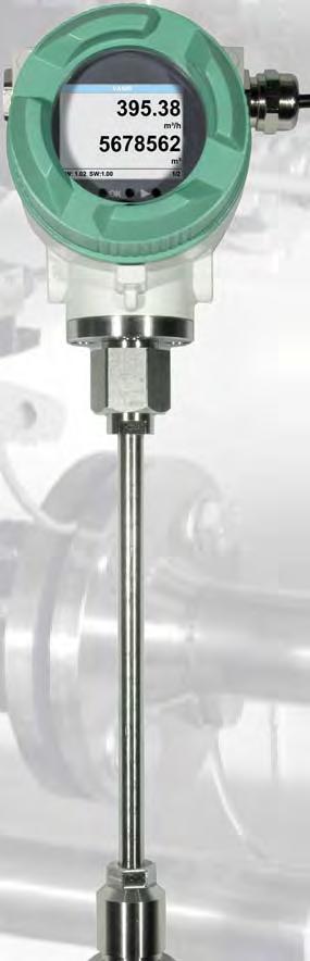


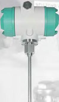

67 Flow VA 550 / 570 DVGW tested Flow 67

68 Flow VA 550 compressed air and gases Application range: Ideal also for the outdoor area Compressed air measurement and distribution Leakage measurement of compressed air and gases Flow measurement of gases like e. g. nitrogen, argon, carbon dioxide, oxygen and so on Flow measurement in vacuum systems DVGW* tested * German Technical and Scientific Association for Gas and Water VA 550 immersion sensor Flow measurement of explosive gases like natural gas, methane, propane, hydrogen with ATEX approval Flow measurement of corrosive, acid gases like e. g. biogas with different gas mixtures Measurement of oxygen and natural gas at gas burners Flow measurement of gas mixtures like e. g. forming gas Applicable in all sectors like e. g.: Chemistry, petro chemistry Natural gas, methane... Pharmaceutical industry Food production Breweries Diaries Power plants Semiconductor/ electronics Automotive industry compensation is not necessary. Due to its robust design, the aluminum die cast housing, the robust sensor tip made from stainless steel 1,4571, the new VA 550/ 570 are of natural gas there is a version with a DVGW admission. Contrary to the previously used bridge circuit the newly developed evaluation electronics records all measured values digitally. This allows very precise and fast measurements with a wide temperature range of up to 180 C. The measuring span is and enables therefore VA 550/ 570 has an integrated Modbus output as a standard with which all parameters like Nm³/h, Nm³, Nm/s, Nl/min, Nl/s, kg/h, kg/min, ft/min, C etc. can be transferred. All parameters can be adjusted directly at the instrument (via display) or via the PI 500 hand-held and a galvanically isolated pulse output for the total consumption. A remote diagnosis can be carried out via Modbus and all relevant parameters can be checked and changed if necessary. So it is possible changed process conditions. Via remote diagnosis and status update e. g. temperature exceedings, failures of the sensor or the calibration date can be determined. 68

.")
 DN Air N2 Ar O2 CO2 Methane natural gas (CH4) R 1/2 16.1 DN 15 0.2...90 0.2...80 0.2...140 0.")


69 Flow VA with integrated measuring section DVGW* tested * German Technical and Scientific Association for Gas and Water Flanged version Version with pipe thread R thread or NPT thread A special feature is the removable measuring head. So the measuring unit can be removed easily and quickly for calibration or cleaning purposes without having to dismount the measuring section intricately. During this period the measuring section is sealed by a closing cap (accessory). The screwing with centering device ensures that the sensor is positioned accurately in the center when screwing it into the measuring section Flow measuring ranges VA 570 Full scale values in Nm³/h Inch Inner pipe diameter (mm) DN Air N2 Ar O2 CO2 Methane natural gas (CH4) R 1/ DN R 3/ DN R DN R 1 1/ DN R 1 1/ DN R DN If you want to measure mixture please contact CS Instruments GmbH. On request we are quite pleased to offer a real gas calibration under process conditions. Measuring ranges of further gases like: Nitrous oxide (N2O), helium (He), propane (C3H8), biogas* (CH4/CO2 60/40) on request! Measuring head removable Screwing with centring device Easy cleaning of the sensor system 69
.")


70 Flow VA immersion sensor Flow sensor for heavy duty industrial applications incl. temperature measurement. compressed air resp. gas lines from 3/4 up to DN Housing IP 67 Outputs: Bus, Ethernet, HART Engraved depth scale for accurate mounting Housing twistable, display twistable by 180 (upside down). Settings adjustable via display, consumption counter resettable All medium-touching parts are made from stainless steel 1,4571 Special measurement technology features: Special mechanical features: Robust impact-proof aluminum die cast housing for the outdoor area IP 67 All medium-touching parts made from stainless steel 1,4571 As immersion sensor suitable for 3/4 up to DN 1000 On request with ATEX approval ATEX II 2G Ex d IIC T4 (up to 120 C) On request with DVGW approval for natural gas (up to 16 bar) Pressure range up to 50 bar, special version up to 100 bar Temperature range up to 180 C, optionally up to 350 C No moving parts, no wearout Sensor tip very robust, easy to clean Easy mounting and dismounting under pressure via 1/2 ball valve Housing twistable, display twistable by 180 Safety ring for mounting and dismounting under pressure Depth scale for precise installation 4 values in the display: Flow, total consumption, velocity, temperature. Units freely adjustable. Min/max values and daily/hours/minutes average values. Time for averaging adjustable All measured values, settings like gas type, inner diameter, serial number and so on retrievable via Modbus RTU Comprehensive diagnosis functions readable at the display or remote access via Modbus like e. g. exceeding of max/min values C, calibration cycle, error codes, serial number. All parameters readable and adjustable Standard version accuracy 1.5 % of m.v. ± 0.3 % of f.s. Precision version accuracy 1.0 % of m.v. ± 0.3 % of f.s. up to Measuring span of 1 : 1000 (0.1 up to 224 m/s) PI 500, PC service software on-site Gas type (air, nitrogen, oxygen, argon and so on) freely adjustable via PC service software or external device DS 400, DS 500, PI 500 Reference conditions C and mbar/hpa freely adjustable Pressure loss negligible 70

71 Flow Easy mounting/dismounting of VA 550 under pressure - without disconnection of the line - without emptying the line Engraved depth scale for precise installation If there is no suitable measuring site with 1/2 ball valve there are two simple possibilities to set up a measuring point: A Weld on a 1/2 screw neck and screw on a 1/2 ball valve Mounting depth = x + y da = outer diameter x = da B Mount spot drilling collar including ball valve By means of the drilling jig it is possible to drill under pressure through the 1/2 ball valve into the existing pipeline. The drilling chips are collected in a x y 2dA A Screw neck Order no.: B Spot drilling collars Order nos.: please see main catalogue Drilling under pressure with CS drilling jig Order no.: Inner diameter of pipe Standard version (92.7 m/s) Max. version (185.0 m/s) High-Speed version (224.0 m/s) Full scale values in Nm³/h * Full scale values in Nm³/h * Full scale values in Nm³/h * Inch mm DN Air** N2 Ar O2 CO2 Methane nat. gas (CH4) Air** N2 Ar O2 CO2 Methane nat. gas (CH4) Air** N2 Ar O2 CO2 Methane nat. gas (CH4) 1/ DN / DN DN / DN / DN DN / DN DN DN DN DN DN DN DN * Nm³/h according to DIN 1343: 0 C, hpa for gases ** ISO 1217: 20 C, 1000 hpa for air Recommended sensor length Sensor length 160 mm Sensor length 220 mm Sensor length 300 mm Measuring ranges of further gases like: Nitrous oxide (N2O), helium (He), propane (C3H8), biogas* (CH4/CO2 60/40) on request! real gas calibration under process conditions. 71


72 Flow For sensors without display there is a PC Service Software available. The following adjustments can be carried out directly at the display resp. by means of the PC Service Software: Adjustment of inner diameter of pipe Selection of gas type Selection of units: e.g. m³/h, m³/min, l/min, kg/s,... Reset of counter Setting of reference conditions (reference temperature/pressure) Zero point adjustment / Scaling of ma output / setting of pulse weight Adjustment of Modbus settings instrument PI 500 work with a laptop is hardly possible we recommend to use the handheld instrument PI 500. the menu navigation in the hand-held instrument. The adjustment possibilities are the same ones as indicated above with PC Service Software or via integrated display. The lithium-ion battery integrated in PI 500 grants the power supply Mobile measurement with hand-held measuring instrument PI 500 Together with the hand-held instrument PI 500 the sensor VA 550 can also be used as a portable measuring solution. PI 500 has an integrated data logger for long-term storage. The data can be exported to a USB stick. Furthermore, additional sensors can be connected to PI 500 like e. g. pressure sensors, dew point sensors, temperature sensors and optional third-party sensors with the following signals: 0...1/10 V, 0/ ma, Pt 100, Pt 1000, pulse, Modbus. Evaluation with chart recorder DS 500 / DS 400 For applications without process control or if additional data loggers are required VA 550 can also be operated with the chart recorders DS 500 or DS 400. It is possible to connect up to 12 sensors to one DS 500 and up to 4 sensors to one DS 400. The data logger (for up to 100 million measured values) can be evaluated via USB stick or via Ethernet interface. 72


73 Flow The optical keys integrated in the display also function through the glass pane. without having to open the housing. In case of conventional keys the housing has to be opened for operation. In an explosive area this is often not possible. SPS Modbus interface ingetrated as a standard Modern building management systems require modern sensors with digital Modbus interface. 3 internal counters: 1 x total counter non-deletable, 1 x total counter deletable, freely adjustable counter between 1 minute and 1 day deletable, e. g. 1/2 hours counter, day counter Gas/air temperature Additional average value calculations: For all parameters freely adjustable from 1 minute to 1 day, e. g. 1/2 hours average value, average day value as well as diagnosis values like: Date of the last calibration Maximum temperature which was reached Sensor diagnosis, error codes can be accessed via the Modbus RTU protocol. P R O F I B U S P R O F I N E T Optionally: Connection to different Bus systems There are different options available for connection to modern Bus systems: Ethernet interface (Modbus-TCP) HART Ethernet Modbus-TCP HART 73
74 Flow Technical data VA 550/ 570 Measuring range VA 550: Accuracy: accuracy class (m.v.: of meas. value) (f.s.: of full scale) Accuracy indications Repeatability: Measuring principle: Response time: Operating temperature range probe tube/display unit: Adjustment possibilities via display, external hand-held meter PI 500, PC Service Software, remote diagnosis: Adjustment possibilities via external device DS 400, DS 500 Outputs: Burden: ,7 Nm/s, standard version* Nm/s, max. version* Nm/s, high speed version* * measuring ranges Nm³/h for different pipe ranges * all measured values referred to DIN 1343 standard conditions 0 C and 1013 mbar ex factory ± 1.5 % of m.v. ± 0.3 % of f.s. on request ± 1.0 % of m.v. ± 0.3 % of f.s. referred to ambient temperature 22 C ± 2 C, system pressure 6 bar 0.25 % of m.v. in case of correct mounting (mounting aid, position, inlet section) is based on the cooling down of a heated sensor PT 45 by bypassing gas. The ambient temperature is measured with a PT 100. An additional pressure and temperature compensation is not necessary. t90 < 3 s C probe tube C high temperature version, probe tube C display unit C for ATEX version Nm³/h, Nm³/min, Nl/min, l/s, ft/min, cfm, kg/h, kg/min, inner diameter, reference conditions volume suppression, scaling of analogue output ma, pulse/alarm, error codes and so on Gas type Modbus RTU, 2 x ma active/passive for weight freely selectable), alarm max. 48 VDC 0.5 A 500 Ohm 3 internal counters: 1 x total counter non-deletable, 1 x total counter deletable, freely adjustable counter between 1 minute and 1 day deletable, e. g. 1/2 hours counter, day counter Additional average value calculation: Protection class : IP 67 Material: Screw-in thread: Operating pressure VA 550: Operating pressure VA 570: Power supply: Approval: for all parameters freely adjustable from 1 minute up to 1 day, e. g. 1/2 hours average value, average day value Housing aluminium die cast, probe tube stainless steel 1,4571, glass G 1/2 ISO 228, NPT 1/2, R 1/2, PT 1/2 available 50 bar; in special version 100 bar (For DVGW approval max. 16 bar) 16 bar; in special version 40 bar VDC, 5 W ATEX II 2G Ex d IIC T4, DVGW H (max.) 134,8(max.) (Ex Version) 99,8 (max.) 156(max.) L 74
75 Flow 134,8(max.) (Ex Version) 99,8 (max.) 156(max.) VA threaded version Outer pipe Conection thread diam. mm Inner pipe diam. mm R 1/ R 3/ R R 1 1/ R 1 1/ * R * *Attention: Shortened inlet section! Please observe the recommended minimum inlet section (length = 10 x inner diameter! L mm L1 mm H mm H1 mm A mm 134,8(max.) (Ex Version) 99,8 (max.) H (max.) H1 (max.) H1 (max.) A A D1 D1 L1 L 156(max.) n x L K D L1 L Measuring section Outer pipe diam. mm Inner pipe diam. mm L mm L1 mm H mm Flange DIN EN H1 mm Ø D Ø K n x Ø L DN x 14 DN x 14 DN x 14 DN x 18 DN * x 18 DN * x 18 *Attention: Shortened inlet section! Please observe the recommended minimum inlet section (length = 10 x inner diameter! 75
76 Flow VA 570 with measuring section Outer thread measuring section A1 R outer thread A1 A2 NPT outer thread A2 A3 Flange version A3 Option display B1 with integrated display B1 B2 without display B2 Option signal output / Bus connection C1 2 x ma analogue output galv. isolated, pulse output RS 485 (Modbus-RTU) C1 C2 RS 485 (Modbus-RTU) C2 C3 C3 C4 RS 485 (Modbus-RTU), pulse output (no analogue outputs) C4 Ethernet interface (Modbus-TCP), RS 485 (Modbus-RTU), pulse output C5 (no analogue outputs) C5 HART protocol, 2 x ma analogue output passive, pulse output RS C6 485 (Modbus-RTU) C6 2 x ma analogue output passive, pulse output RS 485 (Modbus- C7 RTU) C7 Calibration D1 no real gas calibration - gas adjustment via gas constant D1 D2 real gas calibration in the gas type as selected below D2 Gas type E1 compressed air E1 E2 nitrogen (N2) E2 E3 argon (Ar) E3 E4 carbon dioxide (CO2) E4 E5 oxygen (O2) E5 E6 nitrous oxide (N2O) E6 E7 natural gas (NG) E7 E8 helium (He) E8 E9 propane (C3H8) E9 E10 methane (CH4) E10 E11 biogas (Methan 50% : CO2 50%) E11 E90 further gas / please indicate gas type (on request) E90 E91 gas mixture / please indicate mixture ratio (on request) E91 Reference conditions Approvals A 1 B 1 C 1 D 1 E 1 F 1 G 1 H 1 I 1 J 2 K 1 F1 20 C, 1000 hpa F1 F2 0 C, 1013,25 hpa F2 F3 15 C, 981 hpa F3 F4 15 C, 1013,25 hpa F4 Maximum pressure G1 16 bar G1 G2 40 bar G2 Surface condition H1 standard version H1 H2 special cleaning - oil and grease free (e. g. for oxygen applications and so on) H2 H3 Silicone free version including special cleaning oil and grease free H3 Accuracy class Example order code: I1 ± 1.5% of measured value (standard) I1 I2 ± 1% of measured value (precision) I2 Maximum gas temperature at the sensor tip J1 up to 120 C gas temperature (only for ATEX version) J1 J2 up to 180 C gas temperature (standard version) J2 K1 Non-explosive area - no approval K1 K2 ATEX II 2G Ex d IIC T4 K2 K3 DVGW approval (for natural gas) K3 76
77 Flow VA 550 Immersion sensor Measuring range (see table) Screw-in thread B1 G 1/2 outer thread B1 B2 1/2 NPT outer thread B2 B3 PT 1/2 outer thread B3 Mounting length / shaft length C1 220 mm C1 C2 300 mm C2 C3 400 mm C3 C4 500 mm C4 C5 600 mm C5 C7 160 mm C7 Option display D1 with integrated display D1 D2 without display D2 Option signal outputs / bus connection E1 2 x ma analogue output galv. isolated, pulse output RS 485 (Modbus-RTU) E1 E2 E2 E3 E3 E4 RS 485 (Modbus-RTU), pulse output (no analogue outputs) E4 E5 Ethernet interface (Modbus-TCP), RS 485 (Modbus-RTU), pulse output (no analogue outputs) E5 E6 HART protocol, 2 x ma analogue output passive, pulse output RS 485 (Modbus-RTU) E6 E7 2 x ma analogue output passive, pulse output RS 485 (Modbus-RTU) E7 Maximum gas temperature at the sensor tip Approvals A 1 A1 Standard version (92,7 m/s) A1 A2 Max version (185 m/s) A2 A3 High-Speed version (224 m/s) A3 Calibration F1 no real gas calibration - gas adjustment via gas constant F1 F2 real gas calibration in the gas type as selected below F2 Gas type Compressed air G1, nitrogen (N2) G2, argon (Ar) G3, carbon dioxide (CO2) G4, oxygen (O2) G5, nitrous oxide (N2O) G6, natural gas (NG) G7, helium (He) G8, propane (C3H8) G9, G methane (CH4) G10, biogas (methane 50% : CO2 50%) G11, further gas / please indicate gas type (on request) G90, gas mixture / please indicate mixture ratio (on request) G91 Maximum pressure Surface condition B 1 C 1 D 1 E 1 F 1 G 1 H 1 I 1 J 1 K 2 L 1 I1 Standard version I1 I2 Special cleaning - oil and grease free (e.g. for oxygen applications and so on) I2 I3 Silicone free version including special cleaning oil and grease free I3 Accuracy class J1 ± 1,5% of measured value (standard) J1 J2 ± 1% of measured value (precision) J2 K1 up to 120 C gas temperature (only for ATEX version) K1 K2 up to 180 C gas temperature (standard version) K2 L1 Non-explosive area - no approval L1 L2 ATEX II 2G Ex d IIC T4 L2 L3 DVGW approval (for natural gas) L3 Reference conditions Example order code: H1 50 bar H1 H2 100 bar H2 H3 16 bar H3 M1 20 C, 1000 hpa M1 M2 0 C, 1013,25 hpa M2 M3 15 C, 981 hpa M3 M4 15 C, 1013,25 hpa M4 G M
78 Flow Order number VA 550 Description housing High-pressure rig for VA 550 recommended for mounting from 10 to 100 bar Order no order code A_...M_ Order number VA 570 Description Order no order code A_...K_ Closing cap for measuring section in aluminium Closing cap for measuring section stainless steel Further accessories Description Order no. Connection cable for sensors 5 m with open ends Connection cable for sensors 10 m with open ends Mains unit in wall housing V, 10 VA, Hz / 24 VDC, 0.35 A CS Service Software VA 550 incl. interface cable to PC (USB) and power we recommend to use the PI 500: PI 500 portable hand-held instrument with integrated data logger CS Soft Basic - data evaluation in graphic and table form reading out of the measured data via USB or Ethernet Transportation case

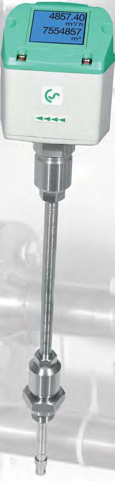


79 Flow VA 500/ 520 Verbrauch 79

80 Flow What are the advantages of the flow measuring technology of CS Instruments? 1) 500 is mounted by means of a standard 1/2 ball valve. During mounting and dismounting the safety ring avoids an uncontrolled ejection of the probe which may be caused by the operating pressure. For the mounting into different pipe diameters VA 500 is available in the following probe lengths: 120, 160, 220, 300, 400 mm. existing pipelines with inner diameters of 1/2 upwards. 1/2 mounting thread 1/2 - ball valve closed mounting depth = x + y da = outer diameter x = da 2 y Engraved depth scale for accurate installation The exact positioning of the sensor in the middle of the pipe is granted by means of the engraved depth scale. The maximum mounting depth corresponds with the resprective probe length. Example: VA 500 with probe length 220 mm has a maximum mounting depth of 220 mm. da x safety ring 2) If there is no suitable measuring site with a 1/2 ball valve present there are two simple possibilities to set up a measuring point: A Weld on a 1/2 screw neck and screw on a 1/2 ball valve B Mount spot drilling collar incl. ball valve (see accessories) By means of the drilling jig it is possible to drill under pressure through the 1/2 ball valve into the existing pipeline. The drilling can be mounted as described under point A. A Screw neck Flow measuring ranges VA 500 for compressed air (ISO 1217:1000 mbar, 20 C) Inner diameter of pipe B Spot drilling collar VA 500 Standard (92.7 m/s) Inch mm Measuring range from to VA 500 Max. (185.0 m/s) Measuring range from to Drilling under pressure VA 500 High-Speed (224.0 m/s) Measuring range from to 1/ DN l/min l/min l/min 3/ DN m³/h m³/h m³/h 3) Due to the large measuring range of the probe even extreme requirements to the consumption measurement (high volume The measuring range is depending on the pipe diameter - see table on the right hand side DN m³/h m³/h m³/h 1 1/ DN m³/h m³/h m³/h 1 1/ DN m³/h m³/h m³/h DN m³/h m³/h m³/h 2 1/ DN m³/h m³/h m³/h DN m³/h m³/h m³/h DN m³/h m³/h m³/h DN m³/h m³/h m³/h DN m³/h m³/h m³/h DN m³/h m³/h m³/h DN m³/h m³/h m³/h DN m³/h m³/h m³/h 80


81 Flow VA Flow sensor for compressed air and gases Contrary to the previously used bridge circuit the newly developed evaluation electronics records all measured values digitally. This leads to a better accuracy also in case of large measuring spans of 1:1000. Special features: RS 485 interface, Modbus-RTU as a standard Incl. temperature measurement Integrated display for m³/h and m³ Usable from 1/2 to 12 (DN 300) Easy installation under pressure ma analogue output for m³/h resp. m³/min Pulse output for m³ Inner diameter adjustable via keypad Consumption counter resettable Adjustable via keys at the display: Gas type, reference conditions, C and mbar, ma scaling, pulse weight thread G 1/2 safety ring Ø 11.7 mm Describtion Order No Standard (92.7 m/s), probe length 220 mm, without display Options for VA 500: Display Z Max. version (185 m/s) Z HighSpeed version (224 m/s) Z % Accuracy of m.v. ± 0,3 % of f.s. Z Probe length120 mm ZSL 0120 Probe length 160 mm ZSL 0160 Probe length 300 mm ZSL 0300 Probe length 400 mm ZSL 0400 Connection cables: Connection cable, 5 m (power supply, analogue output, pulse output) Connection 4 cable, 10 m (power supply, analogue output, pulse output) Further accessories: CS Service Software for FA/VA 500 sensors incl. PC connection set, USB interface and interface adapter to the sensor Mains unit in wall housing V, 10 VA, Hz/24 VDC, 0.35 A AC adapter plug V AC/ 24 V for VA/FA 500/ External wall display chart recorder DS Technical data VA 500 Parameters: Units adjustable via keys at display: Adjustable via keypad: Meas. principle: Sensor: Meas. medium: Gas types adjustable via external devices DS 400, DS 500, PI 500 Meas. range: Accuracy: (m.v.: of meas. value) (f.s.: of full scale) Operating temp.: Operating pressure: Digital output: Analogue output: Pulse output: Power supply: Burden: Inner diameter adjustable via keypad m³/h, l/min (1000 mbar, 20 C) in case of compressed air resp. Nm³/h, Nl/min (1013 mbar, 0 C) in case of gases m³/h, m³/min, l/min, l/s, ft/min, cfm, m/s, kg/h, kg/min counter resettable calorimetric measurement air, gases air, nitrogen, argon, nitrous oxide, CO2, oxygen see table measuring ranges page 80 ± 1.5 % of m.v. ± 0.3 % of f.s. on request ± 1.0 % of m.v. ± 0.3 % of f.s C probe tube C housing up to 50 bar RS 458 interface, Modbus RTU ma for m³/h resp. l/min; on request: scaling for cfm,m³/min, l/min, l/s, ft/ min, m/s 1 pulse per m³ resp. per liter galvanically separated VDC, 5 W Housing: polycarbonate (IP 65) Probe tube: stainless steel, mounting length 220 mm, Ø 10 mm Mounting G 1/2 thread: 81
 DN 15 R 3/4 (DN 20) DN 25 R 1 1/4 (DN 32) DN 40 R 2 (DN 50) Intelligent solutions for ac- for compressed air and gases work according to the approved calorimetric")

82 Flow VA 520 incl. temperature measurement R 1/4 (DN 8) DN 15 R 3/4 (DN 20) DN 25 R 1 1/4 (DN 32) DN 40 R 2 (DN 50) Intelligent solutions for ac- for compressed air and gases work according to the approved calorimetric measuring principle. An additional pressure and temperature compensation is not necessary. Contrary to the previously used bridge circuit the newly developed evaluation electronics records all measured values digitally. This enables very precise and fast measurements. Due to the new evaluation electronics all VA 520 have an integrated Modbus output as a standard. So all parameters can be transferred via Modbus. Due to its compact design it is possible to monitor all compressed air systems from the compressor to the smallest compressed air tool (1/4 to 2 inch) with the new pipe diameters from DN 50 to DN 300. Apart from compressed air also other gases like e.g. nitrogen, oxygen and CO2 can be measured. 82


83 Flow Removal of the measuring device without complete dismounting of the measuring section 1 case of compressed air meters with integrated measuring section the measuring device cannot be removed. For this reason an expensive bypass line is necessary. The design of VA 520 enables the removal and cleaning of the measuring device with e.g. soap water without any dismounting of the measuring section. A closing cap grants a continuous use of the line for the duration of the cleaning. A bypass line is not necessary. The alignment pin grants an accurate installation of the measuring device. 2 Stationary use In most cases the compressed air is not free from oil, condensate, dirt and particles. In the course of time this leads to a soiling of the surement or even a total breakdown. The ket up to now generally cannot be cleaned and will be exchanged if they are soiled. In For stationary use there are the following outputs available for the data transfer to a building management system or PLC: Pulse output (galvanically separated) for the total consumption. 3 4 Mobile use Solution for large pipe diameters can be integrated quickly into the feed hose of a machine. During the shutdown of the machine it is possible to determine the leak the machine is running. The power supply is effected via the power socket by means of the mains unit. For data recording over a longer period of time we recommend to use the compressed air analyzer DS 400 mobile. able for pipe diameters of 2 to DN 300. Its constructively sophisticated design enables the installation into pipes with nominal diameters up to DN 300 even under pressure. The installation is effected by means of standard 1/2 ball valve. 83
 Display twistable by 180 C direction Display shows 2 values at the same time: - Total consumption (counter reading) in m³,l - bzw.")


84 Flow VA The advantages at a glance NEW: Modbus-RTU output ma output for actual (counter reading) Display twistable by 180 C direction Display shows 2 values at the same time: - Total consumption (counter reading) in m³,l - bzw. temperature measurement Values indicated in the display turnable by 180 C, e.g. in case of overhead installation Measuring device removable: Dismounting of the whole measuring section is not necessary, no bypass required Screw-in thread: Easy installation into the existing pipeline due to integrated measuring section (suitable for 1/4, 1/2, 3/4, 1, 1 1/4, 1 1/2 or 2 lines) Application-technological features of the measuring section (inlet and outlet section) The integrated Modbus interface enables the connection to superordinated control systems like energy management systems, building management systems, SPS, SCADA,... Easy and affordable installation Units freely selectable via keys at the display m³/h, m³/min, l/min, l/s, kg/h, kg/min, kg/s, cfm Compressed air counter up to m³. Resetable to zero via keypad Analogue output ma, pulse output (galvanically separated) High measuring accuracy also in the lower measuring range (ideal for leakage measurement) Negligibly small loss of pressure Calorimetric measuring principle, no additional pressure and temperature measurement necessary, no mechanically moved parts Comprehensive diagnosis functions can be read out at the display or by remote access via Modbus-RTU like e. g. exceeding Max./Min values C, calibration cycle, error codes, serial number. All parameters can be read out and changed via Modbus At the touch of a button: Reset of counter reading selection of units zero-point adjustment, leak Application range of VA 520: Compressed air balancing, compressed air consumption measurement Leckage air/leak rate determination Mobile compressed air measurement in front of single machines / plants Flow measurement of process gases like e.g. nitrogen, CO2, oxygen, argon, nitrous oxide Flow measurement at nitrogen generators 84
85 Flow Flow measuring ranges VA 520 for compressed air (ISO 1217:1000 mbar, 20 C) Connection thread Description Outer pipe dia. mm Inner pipe dia. mm Measuring range from to R 1/ l/min R 1/ m³/h R 3/ m³/h R m³/h R 1 1/ m³/h R 1 1/ m³/h 475* R m³/h 475* *Attention: Shortened inlet section! Please observe the recommended minimum inlet section (length = 10 x inner diameter) on site! Order No. Stainless steel Order No. Stainless steel Option High-pressure version PN 40 Z Option 1 % Accuracy of m.v. ± 0,3 % of f.s. Z Special measuring range VA 520 according to customer`s requirements Z Connection cables: Connection cable 5 m (power supply, analogue output) Connection cable 10 m (power supply, analogue output) Further accessories: Closing cap for meas. section (Material: Aluminium) Closing cap for meas. section (Material: Stainless steel ) CS Service Software for FA/VA sensors incl. PC connection set, USB interface and interface adapter to the sensor Mains unit in wall housing V, 10 VA, Hz/24 VDC, 0.35 A AC adapter plug V AC/ 24 V for VA/FA 500/ L mm L1 mm H mm H1 mm A mm Technical data VA 520 Parameters: Units adjustable via keys at display: Meas. principle: Sensor: Meas. medium: Gas types adjustable via external device DS 400, DS 500, PI 500 Meas. range: Accuracy: (m.v.: of meas. value) (f.s.: of full scale) Operating temp.: C Operating pressure: Digital output: Analogue output: Pulse output: Power supply: Burden: Housing: Meas. section: Mounting thread meas. section: m³/h, l/min (1000 mbar, 20 C) in case of compressed air resp. Nm³/h, Nl/min (1013 mbar, 0 C) in case of gases m³/h, m³/min, l/min, l/s, ft/min, cfm, m/s, kg/h, kg/min calorimetric measurement air, gases air, nitrogen, argon, nitrous oxide, CO2, oxygen see table at the left ± 1.5 % of m.v. ± 0.3 % of f.s. on request ± 1.0 % of m.v. ± 0.3 % of f.s. up to 16 bar optional up to PN 40 RS 485 interface, Modbus- RTU ma for m³/h resp. l/min 1 pulse per m³ resp. per liter galvanically separated VDC, 5 W polycarbonate stainless steel, or R 1/4, R 1/2, R 3/4, R 1, R 1 1/4, R 1 1/2, R 2 external thread. 85
 Measuring device removable: Dismounting of the whole measuring section is not necessary, no bypass required Display shows 2 values at the same time: -")

 The integrated Modbus interface enables the connection to superordinated control systems like energy management systems, building management systems, SPS,")

86 Flow VA The advantages at a glance NEW: Modbus-RTU output Display twistable by 180 C direction ma output for actual (counter reading) Measuring device removable: Dismounting of the whole measuring section is not necessary, no bypass required Display shows 2 values at the same time: - Total consumption (counter reading) in m³,l - bzw. temperature measurement Values indicated in the display turnable by 180 C, e.g. in case of overhead installation Easy installation into the existing pipeline due to integrated measuring section and (according to EN PN 40) Application-technological features of the measuring section (inlet and outlet section) The integrated Modbus interface enables the connection to superordinated control systems like energy management systems, building management systems, SPS, SCADA,... Easy and affordable installation Units freely selectable via keys at the display m³/h, m³/min, l/min, l/s, kg/h, kg/min, kg/s, cfm Compressed air counter up to m³. Resetable to zero via keypad Analogue output ma, pulse output (galvanically separated) High measuring accuracy also in the lower measuring range (ideal for leakage measurement) Negligibly small loss of pressure Calorimetric measuring principle, no additional pressure and temperature measurement necessary, no mechanically moved parts Comprehensive diagnosis functions can be read out at the display or by remote access via Modbus-RTU like e. g. exceeding Max./Min valuese C, calibration cycle, error codes, serial number. All parameters can be read out and changed via Modbus At the touch of a button: reset of counter reading selection of units zero-point adjustment, leak Application range of VA 520: Compressed air balancing, compressed air consumption measurement Leckage air/leak rate determination Flow measurement of process gases like e.g. nitrogen, CO2, oxygen, argon, nitrous oxide Flow measurement at nitrogen generators 86
87 Flow Flow measuring ranges VA 520 for compressed air (ISO 1217:1000 mbar, 20 C) Measuring section Description Outer pipe dia. mm Inner pipe dia. mm Measuring range from to Flange DIN EN Order No Option High-pressure version PN 40 Z Option 1 % Accuracy of m.v. ± 0,3 % of f.s. Z Special measuring range VA 520 according to customer`s requirements Z Connection cables: Connection cable 5 m (power supply, analogue output) Connection cable 10 m (power supply, analogue output) Further accessories: Closing cap for meas. section (Material: Aluminium) Closing cap for meas. section (Material: Stainless steel ) CS Service Software for FA/VA sensors incl. PC connection set, USB interface and interface adapter to the sensor Mains unit in wall housing V, 10 VA, Hz/24 VDC, 0.35 A AC adapter plug V AC/ 24 V for VA/FA 500/ L mm L1 mm H mm H1 mm ØD ØK n x ØL DN m³/h x 14 DN m³/h x 14 DN m³/h x 14 DN m³/h x 18 DN m³/h 475* x 18 DN m³/h 475* x 18 *Attention: Shortened inlet section! Please observe the recommended minimum inlet section (length = 10 x inner diameter) on site Technical data VA 520 Parameters: Units adjustable via keys at display: Meas. principle: Sensor: Meas. medium: Gas types adjustable via external device DS 400, DS 500, PI 500 Meas. range: Accuracy: (m.v.: of meas. value) (f.s.: of full scale) m³/h, l/min (1000 mbar, 20 C) in case of compressed air resp. Nm³/h, Nl/min (1013 mbar, 0 C) in case of gases m³/h, m³/min, l/min, l/s, ft/min, cfm, m/s, kg/h, kg/min calorimetric measurement air, gases air, nitrogen, argon, nitrous oxide, CO2, oxygen see table at the left ± 1.5 % of m.v. ± 0.3 % of f.s. on request ± 1.0 % of m.v. ± 0.3 % of f.s. Operating temp.: C Operating press.: up to 16 bar Optional up to PN 40 Digital output: RS 485 interface, Modbus-RTU Analogue output: ma for m³/h resp. l/min Pulse output: 1 pulse per m³ resp. per liter galvanically separated Power supply: VDC, 5 W Burden: Housing: polycarbonate (IP 65) Meas. section: stainless steel or Flanges: DIN EN , Groove-faced and tongue-faced on request 87
88 Flow DS 400 Flow station for compressed air and gases Chart recorder DS graphic display with touch screen - shows the progression of the measured values in graphic form sensors USB interface for reading out the data logger via USB stick Flow measuring ranges VA 500 for compressed air (ISO 1217:1000 mbar, 20 C) Inner diameter of pipe VA 500 Standard (92.7 m/s) VA 500 Max. (185.0 m/s) VA 500 HighSpeed (224.0 m/s) Inch mm Measuring range from to Description Measuring range from to Flow measurement DS 400 for installation into existing pipelines consisting of: sensor length 220 mm Measuring range from to 1/ DN l/min l/min l/min 3/ DN m³/h m³/h m³/h DN m³/h m³/h m³/h 1 1/ DN m³/h m³/h m³/h 1 1/ DN m³/h m³/h m³/h DN m³/h m³/h m³/h 2 1/ DN m³/h m³/h m³/h DN m³/h m³/h m³/h DN m³/h m³/h m³/h DN m³/h m³/h m³/h DN m³/h m³/h m³/h DN m³/h m³/h m³/h DN m³/h m³/h m³/h DN m³/h m³/h m³/h Order No Options for DS 400 Option: Integrated data logger for 100 million measured values Z Option: Integrated Ethernet and RS 485 interface Z Option: 2 additional sensor inputs for analogue sensors Z (pressure sensors, temperature sensors etc.) Option: Integrated webserver Z Max. version (185 m/s) Z HighSpeed version (224 m/s) Z Option 1 % Accuracy of m.v. ± 0,3 % of f.s. Z Sensor length 120 mm ZSL 0120 Sensor length 160 mm ZSL 0160 Sensor length 300 mm ZSL 0300 Sensor length 400 mm ZSL 0400 Further accessories CS Soft Basic - data evaluation in graphic and table form - reading out of measured data via USB or Ethernet Calibration additional sensor inputs for pressure sensors, current meters and so on Option: Data logger for 100 million measured values (2 GB SD card) Option: Ethernet and RS 485 interface (Modbus protocol) Option: Webserver Option: CS Soft Basic - comfortable evaluation of the measured data Flow sensor VA 500 Easy installation and removal under pressure via 1/2 ball valve Several gas types - freely adjustable at DS 400 Usable from 1/2 to 12 DN 300 Diameter freely adjustable at DS 400 Output for ma for m³/h mounting depth = x + y da = outer diameter x = da 2 da y x engraved depth scale 88


89 Flow Easy operation via touch screen the respective inner diameter of the pipe in the menu of DS 400. Furthermore, the unit, the gas type as well as the reference conditions can be entered. The counter can be set to zero if required. Graphic view In the graphic view all measured values are indicated as curves. It is possible to browse back on the time axis maximum 24 h, with data logger back to the start of the measurement). Data logger Measured values are stored in DS 400 by means of the option integrated data logger. The time interval can be freely set. Further- time and the end time of the data recording. Readout of the measured data via USB interface or via the optional Ethernet interface. Selection of the language DS 400 speaks several languages. The required language can be selected by means of the select button. All relevant parameters at a glance the velocity in m/s. Technical data VA 500 Parameters: Units adjustable via keys at display: Adjustable via keypad: Meas. principle: Sensor: Meas. medium: Gas types adjustable via external device DS 400, DS 500, PI 500 Accuracy: (m.v.: of meas. value) (f.s.: of full scale) Operating temp.: Operating pressure: Digital output: Analogue output: Pulse output: Power supply: Burden: Housing: Technical data DS 400 Dimensions: 118 x 115 x 98 mm IP 54 (wall housing) 92 x 92 x 75 mm (panel mounting) Inputs: 2 digital inputs for VA 500/520 Interface: USB Power supply: VAC, Hz Accuracy: please see VA 500 Alarm outputs: 2 relays, (pot.-free) Options: Data logger: 100 million measuring values start/stop time, measuring rate freely adjustable 2 additional sensor inputs: m³/h, l/min (1000 mbar, 20 C) in case of compressed air resp. Nm³/h, Nl/min (1013 mbar, 0 C) in case of gases m³/h, m³/min, l/min, l/s, ft/min, cfm, m/s, kg/h, kg/min on, counter resettable calorimetric measurement air, gases air, nitrogen, argon, nitrous oxide, CO2, oxygen ± 1.5 % of m.v. ± 0.3 % of f.s. on request ± 1.0 % of m.v. ± 0.3 % of f.s C probe tube C housing up to 50 bar RS 458 interface, Modbus RTU ma for m³/h resp.l/min; on request: scaling for cfm,m³/min, l/min, l/s, ft/min, m/s 1 pulse per m³ resp. per liter galvanically separated VDC, 5 W polycarbonate Probe tube: stainless steel, mounting length 220 mm, Ø 10 mm Mounting G 1/2 thread: for connection of pressure sensors, temperature sensors, clamp-on ammeters, third-party sensors with ma 0 to 10 V, Pt 100, Pt
90 Flow DS chart recorder for all relevant parameters of compessed air Software options: Integrated webserver Mathematic calculation function Totalizer function Hardware options: Integrated data logger Ethernet / RS 485 interface additional sensor inputs (digital or analogue) selectable The 2 sensor inputs board 1 and 2 can be selected according to the required sensors: Digital Digital Digital Digital m³/h, m³ Ctd A, kw/h optional Flow sensor Dew point sensor Current meters MOD BUS Thirdparty sensors with RS 485 Analogue Analogue Analogue Analogue bar A C C Pressure sensor Standard equipment: USB interface 3.5 graphic display with touch screen Integrated mains unit for supply of the sensors ma output of all connected active sensors Pulse output (for total consumption) in case of 2 alarm relays (pot.-free switch-over contacts, max. 230 V, 3 A) Clampon ammeter Temperature sensor ma ma V Pulse Pt 100 Pt 1000 Thirdparty sensors analogue output Description Order No. 2 sensor inputs board 1 2 sensor inputs board 2 Digital (Z ) D DS Mobile chart Digital (Z ) Digital (Z ) DD recorder with graphic display and touch screen Digital (Z ) Analogue (Z ) DA Analogue (Z ) A Analogue (Z ) Analogue (Z ) AA Options Option: Integrated data logger for 100 million measured values Z Option: Integrated Ethernet and RS 485 interface Z Option: Integrated webserver Z Option: Mathematics calculation function for 4 freely selectable channels, Z (virtual channels): addition, subtraction, division, multiplication Option: Totalizer function for analogue signals Z Z Further accessories CS Soft Basic - data evaluation in graphic and table form - reading out of the measured data of DS 400 via USB or Ethernet CS Soft Network - Database Client/Server Solution (up to 5 DS 400) - database (MySQL) to Server - data evaluation via Client-Software CS Soft Network - Database Client/Server Solution (up to 10 DS 400) - database (MySQL) to Server - data evaluation via Client-Software CS Soft Network - Database Client/Server Solution (up to 20 DS 400) - database (MySQL) to Server - data evaluation via Client-Software CS Soft Network - Database Client/Server Solution (>20 DS 400) - database (MySQL) to Server - data evaluation via Client-Software Technical data DS 400 Dimensions: 118 x 115 x 98 mm IP 54 (wall housing) 92 x 92 x 75 mm (panel mounting) Inputs: 2 digital inputs for FA 510 resp. VA 500/520 Interface: USB Power supply: VAC, Hz Accuracy: please see VA 500 Alarm outputs: 2 relays, (pot.-free) Options: Data logger: 100 million measuring values start/stop time, measuring rate freely adjustable 2 additional sensor inputs: Input signals Current signal internal or external power supply Measuring range Resolution Accuracy Input resistance Voltage signal Measuring range Resolution Accuracy Input resistance Voltage signal Measuring range Resolution Accuracy Input resistance RTD Pt 100 Measuring range Resolution Accurancy RTD Pt 1000 Measuring range Resolution Accuracy Pulse Measuring range for connection of pressure sensors, temperature sensors, clamp-on ammeters, third-party sensors with ma 0 to 10 V, Pt 100, Pt 1000 (0...20mA/4...20mA) ma ma ± 0.03 ma ± 0.05 % (0...1 V) V 0.05 mv ± 0.2 mv ± 0.05 % ( V / 30 V) V 0.5 mv ± 2 mv ± 0.05 % C 0.1 C ± 0.2 C ( C) ± 0.3 C (further range) C 0.1 C ± 0.2 ( C) min pulse length 500 μs frequency khz max. 30 VDC 90
 Z695 5003 High Speed version (224 m/s) Z695 5002 Sensor length 120 mm ZSL 0120 Sensor length 160 mm ZSL 0160 Sensor length 300 mm ZSL 0300 Sensor length 400 mm ZSL 0400 Flow meters")
91 Flow Suitable probes from the CS Instruments product range Flow sensors VA 500: Order No Option for VA 500: Max. version (185 m/s) Z High Speed version (224 m/s) Z Sensor length 120 mm ZSL 0120 Sensor length 160 mm ZSL 0160 Sensor length 300 mm ZSL 0300 Sensor length 400 mm ZSL 0400 Flow meters VA 520: Flow meter VA 520 with integrated measuring section, (R 1/4 DN 8) Flow meter VA 520 with integrated measuring section, (R 1/2 DN 15) Flow meter VA 520 with integrated measuring section, (R 3/4 DN 20) Flow meter VA 520 with integrated measuring section, (R 1 DN 25) Flow meter VA 520 with integrated measuring section, (R 1 1/4 DN 32) Flow meter VA 520 with integrated measuring section, (R 1 1/2 DN 40) Flow meter VA 520 with integrated measuring section, (R 2 DN 50) Dew point sensors: Standard measuring chamber for compressed air up to 16 bar Connection cable 5 m Connection cable 10 m Pressure sensors: (further pressure sensors please see page 9) Standard pressure sensor CS 16 from 0 16 bar, ± 1 % accuracy of full scale Standard pressure sensor CS 40 from 0 40 bar, ± 1 % accuracy of full scale Temperature sensors: Bendable temperature probe, Pt100 Class B, length 300 mm, 2 m probe connection cable Screw-in temperature probe Pt 100 Class A, length: 300 mm with measuring transducer 4 to 20 ma = -50 to +500 C ( 2-wire technology) Indoor/outdoor temperature probe C Temperature probe cable Pt 100, Class A, length: 300 mm, Ø 6 mm, C, with 5 m connection cable with open ends Temperature probe cable Pt 100, Class A, length: 150 mm, Ø 6 mm, C with 5 m connection cable with open ends Clamp screwing 6 mm, G 1/2, PTFE clamping, pressure-tight up to 6 bar Clamp screwing 6 mm, G 1/2, VA clamping, pressure-tight up to 10 bar Connection cables for pressure sensors / temperature sensors: Connection cable 5 m Connection cable 10 m Clamp-on ammeters: Clamp-on ammeter A TRMS incl. 5 m connection cable with open ends Clamp-on ammeter A TRMS incl. 3 m connection cable with open ends Optional third-party sensors 0/ ma, 0...1/10/30 V, Pt 100 / Pt 1000, KTY, pulse, RS 485 Modbus connectable. CS PM 210 current/effective power meter for panel mounting, current transformer from 100 A to 2000 A connectible Current transformer 100/5 A connectible to current/effective power meter for panel mounting (for cabels up to Ø 21 mm) Current transformer 500/5 A connectible to current/effective power meter for panel mounting (for cabels up to Ø 21 mm) Connection cable to DS 400, 5 m, with open ends Connection cable to DS 400, 10 m, with open ends

92 Flow CS Soft Basic - evaluation of measured data for single computers USB-stick Ethernet The measured data stored in the data logger integrated in DS 400 can be read-out via USB stick. If DS 400 has the optional Ethernet interface the measured data can also be read-out over big distances via the computer network Graphic evaluation All measurement curves are indicated in different colours. All necessary functions like free zoom, selection/deselection of single measured curves, free selection of time periods, scaling of the axis, selection of colours and so on are integrated: Table view All measured points are listed with the exact time interval. The desired measuring channels with the measuring site name can be selected via the diagram explorer. Statistics All necessary statistics data are apparant at a glance. So the user can quickly see which minimum or maximum measured values occurred at which time and for how long
93 Flow CS Soft Network - evaluation of the measured data for several computers in the network By means of the CS Soft Network an optional number of DS 500/ DS 400 instruments can be evaluated via Ethernet. The software stores the measured data of all DS 500 / DS 400 cyclically (cycle freely selectable) in a SQL database on the server. In case of an exceeding of the stored alarm values the software automatically sends an SMS or an . Furthermore, different user levels single staff members only can access the measured data of certain DS 500 / DS 400. The evaluation of the measured data can be carried out by means of the client software from each PC within the company. ETHERNET SERVER WORLD WIDE WEB Functions of the CS Soft Network (Server): Automatic data storage in My SQL database (cycle freely programmable) User administration sion via SMS/ Access to the measured values via the webserver Functions of the CS Soft Network (Client): Indication of current measured values Graphical chart with zoom function In table form Report generation (standard report with Min-Max values, number of alarm exceedings, moment of alarm exceeding) Automatic consumption report Ethernet WORLD WIDE WEB Connection to Bus system With the option Webserver (order no. Z ) DS 400 can be contacted without any special software from each web browser (eg. Mozilla Firefox, Microsoft Internet Explorer ). The access can also be done via the World Wide Web. The webserver indicates the actual measured values of all sensors as well as the status of the alarm relays and the logger status in the web browser. With the option Ethernet / RS interface (order no. Z ) DS 400 can be connected to customer-owned Bus system (e.g. PLC, building management system BMS, central control system, SCADA,...). RS 485 network (Modbus RTU) or Ethernet (Modbus/TCP) The measured values of all sensors can be retrieved via Modbus protocol. A detailed protocol description is enclosed with each DS 400 instrument. When using the Ethernet interface the IP address at DS 400 can be freely adjusted. As an alternative DS 400 waits for the address allocation by a DHCP server. 93
 it is possible to calculate sors.")


94 Flow Innovations By means of the option mathematics calculation function (order no. Z ) it is possible to calculate sors. Of course the new virtual value sum of all sensors can also be indicated graphically and stored in the data logger. Screen-shot function By means of the print key it is possible to store the actual a USB stick and print it out at the PC without any additional software. This is ideal for documentation of the measured values/ measured curves on-site. Coloured measured curves a service report. Totalizer function the market just have a ma analogue output for the By means of the option totalizer function DS 400 can menu at any time. 94
95 Flow Consumption and Cost saving In Germany 60,000 compressed air plants use 14,000,000,000 kwh electrical energy per year. 15 to 20 % could be easily saved (Peter Radgen, Frauenhofer Institut, Karlsruhe). Most of these costs are caused by leakages in the compressed air system. The air escapes unused. 1 leak with a diameter of 1 mm causes costs of approximately 270 EUR/year The leak detector LD 400 of CS Instruments GmbH will be paied off after 4 leakages (please see page 94-95) Cost distribution in compressed air systems: Maintenance Electricity Equipment Example for a calculation of leakage costs at different pressure: Leak Ø (mm) Air loss at 6 bar (l/s) Air los at 12 bar (l/s) Energy loss kwh at 6 bar Energy loss kwh at 12 bar Costs p.a. at 6 bar ,488 6,960 Costs p.a. at 12 bar ,984 16, ,840 63,

 is transferred to the consumption sensors VA 500/ VA 520 or to a separate building management system (mbs). Two in closed circular pipelines can be measured precisely. Description Order No.")
96 Flow VA 409 Flow direction switch for compressed air systems direction indication serves for determination gases especially in closed circular pipelines. - air can be determined quickly and safely. Compared with the former mechanical - direction quickly and without any mechanical movement. Special features detects smallest changes <0.1 m/s referred to 20 C and 1000 mbar no mechanical wear parts easy installation under pressure The direction information in form of a potential-free contact (normally closed max. 60 VDC, 0.5 A) is transferred to the consumption sensors VA 500/ VA 520 or to a separate building management system (mbs). Two in closed circular pipelines can be measured precisely. Description Order No. Flow direction switch VA Mains unit in wall housing Connection cable VA/FA Series 400, 5 m with M12 plug Connection cable VA/FA Series 400, 10 m with M12 plug Technical data VA 409 Detection range direction: Measuring principle: < 0.1 m/s referred to 20 C and 1000 mbar calorimetric measurement Sensor: Pt 30/ Pt 700/ Pt 330 Measuring air, gases medium: Operating temp.: C probe tube C housing Operating up to 16 bar pressure: Power supply: 24 VDC, 40 ma Power input: max. 80 ma up to 24 VDC Protection class: IP 54 EMV: acc.to DIN EN Connection: 2 x M12, 5-pole, plug A and plug B 2 potential-free contacts: Housing: Probe tube: Mounting thread: G 1/2 Diameter 65 mm housing: Flow direction: 2 LEDs 2 x U max. 60 VDC, l max 0,5 A (normally closed); on request: Normally open polycarbonate stainless steel, 1,4301, length 160 mm, Ø 10 mm, safety ring Ø 11.5 mm, longer probes on request 96
97 Flow Flow station DS 400 with direction indication in one direction - pressed air is not counted twice. Special features when doing the cost calculation of the com- pressed air is counted twice Flow station DS 400 Special features precise consumption measurement in both directions (m³ resp. l) forwarding of the analogue output and of the 97


98 Flow Useful accessories: Measuring sections Measuring sections for precise measurements Measuring section made of stainless steel incl. ball valve, up to DN 65 (R2 1/2 ) with Measuring section 1/2 External thread Pipe (outerø x wall thickness) Total length Order no. R 1/ x 7.0 mm 180 mm R 1/ x 2.6 mm 500 mm R 3/ x 2.6 mm 600 mm R x 3.2 mm 750 mm R 1 1/ x 3.2 mm 900 mm R 1 1/ x 3.2 mm 1000 mm R x 3.6 mm 1250 mm R 2 1/ x 3.6 mm 1500 mm DN 80/ x 2.0 mm 1850 mm DN 100/ x 2.0 mm 2104 mm DN 125/ x 3.0 mm 2860 mm DN 150/ x 3.0 mm 3110 mm Measuring section 1/4 Drilling jig for drilling under pressure By means of a special drilling device a measuring site with 1/2 ball valve can be easily set up within a few minutes. Drilling jig High-pressure protection Drilling under pressure Description Order No. Drilling jig incl. drill (Ø 13 mm) High-pressure protection recommended for installation from 10 to 50 bar


99 Flow Useful accessories: Spot drilling collars If there is no measuring site with 1/2 ball valve present it can be set up by means of spot drilling collars. The spot drilling collar is imposed onto the pipe and tightened via thread rods. The enveloping rubber gasket is pressure-tight up to 10 bar. By means of the drilling jig it is possible to drill through the 1/2 ball valve into the existing pipe. Important: Please indicate the exact outer diameter of the existing pipe when placing the order resp. please select the suitable spot drilling collar from the adjoining list. Spot drilling collar Description DN Order no. Spot drilling collar for pipe Ø mm, Length: 100 mm* Spot drilling collar for pipe Ø mm, Length: 100 mm* Spot drilling collar for pipe Ø mm, Length: 150 mm* Spot drilling collar for pipe Ø mm, Length: 200 mm* Spot drilling collar for pipe Ø mm, Length: 200 mm* Spot drilling collar for pipe Ø mm, Length: 200 mm* Spot drilling collar for pipe Ø mm, Length: 200 mm* Spot drilling collar for pipe Ø mm, Length: 200 mm* Spot drilling collar for pipe Ø mm, Length: 200 mm* Spot drilling collar for pipe Ø mm, Length: 200 mm* Spot drilling collar for pipe Ø mm, Length: 200 mm* Spot drilling collar for pipe Ø mm, Length: 200 mm* Spot drilling collar for pipe Ø mm, Length: 200 mm* Spot drilling collar for pipe Ø mm, Length: 200 mm* Spot drilling collar for pipe Ø mm, Length: 200 mm* Spot drilling collar for pipe Ø mm, Length: 200 mm* Spot drilling collar for pipe Ø mm, Length: 200 mm* Spot drilling collar for pipe Ø mm, Length: 200 mm* Spot drilling collar for pipe Ø mm, Length: 250 mm* Spot drilling collar for pipe Ø mm, Length: 250 mm* Spot drilling collar for pipe Ø mm, Length: 250 mm* Spot drilling collar for pipe Ø mm, Length: 250 mm* Spot drilling collar for pipe Ø mm, Length: 250 mm* Spot drilling collar for pipe Ø mm, Length: 300 mm* Spot drilling collar for pipe Ø mm, Length: 300 mm* Spot drilling collar for pipe Ø mm, Length: 300 mm* *incl. 1/2 ball valve Thickness meter CS 0495 The entry of the correct inner diameter is essential for an accurate consumption measurement. The thickness meter CS 0495 enables a quick, easy and accurate measurement of the wall thickness of pipes. So the determination of the inner diameter becomes very easy. Description Order No. Thickness meter CS 0495 including case and calibration block Technical data CS 0495 Meas. range: mm, Inch Meas. principle: ultrasonic Measured materials: Calibration block: Resolution: steel, cast iron, aluminium, copper, brass, zinc, quartz glass, polyethylene, PVC, grey iron, nodular cast iron included in shipment 0.1 mm Accuracy: ± (0.5 % n+ 0.1) Power supply: 4 x 1.5 V AA (UM-3) batteries Dimensions: Weight: 160 x 68 x 32 mm 208 g 99


100 Flow Calibration of flow sensors and flow stations - instruments of CS Instruments as well as of other manufacturers. High precision reference measuring instruments grant an accuracy of up 0.5 % of the measured value. Special features Due to digital data transfer only the enabling the display unit DS 400 to stay on-site at all times Calibration range: Accuracy of the reference: from 0 to 4,000 m³/h under pressure between 0.5 and 1 % of the measured value Description Order No on request Real gas calibration
101 Flow Notes: 101


102 Flow Each factory needs compressed air, however, often it is not realized that compressed air is one of the most expensive types of energy. Therefore, the intelligent use of compressed air holds an enormous potential for saving energy. In most cases the user mainly concentrates on the production, i. e. on the compressors. In order to save energy very often new compressors, control systems or heat recovery systems are installed
103 Flow If we talk about operational costs of compressed air plants we are actually talking about the energy costs as they make up about 70 to 80 % of the total costs of a compressed air plant. Depending on the size of the plant this means considerable operating costs. Even in smaller plants this may quickly add up to 10,000 to 20,000 per year. This is an amount which can be considerably reduced even in case of well operated and maintained plants. In case of a three shift operation with 200 kw compressor performance a bad compressed air distribution can create redundant energy costs of more than 50,000 per year. This mainly concerns to the elimination of leakages and the correct diameters of the compressed air lines for minimization of the pressure losses. Energy resources like electricity, water or gas are usually monitored and therfore the costs are transparent. Contrary to compressed air, a water leak is usually found quickly due to the visibility of the leak and therefore they are eliminated immediately. Compressed air leaks are often not noticed and can silently cause a lot of unnecessary costs, even during production downtime or over the weekend. Also during that time compressors are running continuously in order to establish a constant pressure within the system. In case of compressed air systems which have grown during the years the leakage rate can be between 25 and 35 per cent. They are the busiest consumers of compressed air, working all around 365 days a year. Not included are the hidden costs of producing clean and dry compressed air. Refrigeration and desiccant driers are producing dry air with high running costs involved. Air that is then later lost through leaks within the system. At constantly rising energy costs these potential energy savings have to be implemented in order to stay competitive within the market. Only if the consumption of single machines or plants becomes known and transparent for all it is possible to make use of possible savings. However, often any knowledge about the leak ratio is missing. In the following we show you how you can easily determine the leakage amounts in your company. Formerly the simple but inaccurate container method was applied very often A simplified determination of the leakages is possible by means of the emptying of the tank. For carrying out this measurement you just need a clock and a manometer. Furthermore you should know the storage volume of the tank as well as of the compressed air system. For measurement first the tank and the compressed air system are set to the upper cut-out pressure value. All compressed air consumers have to be switched off. Then the compressor is switched off and there will be no compressed air feeding into the system. Now the time T is measured which passes by until there is a pressure drop of 1 to 2 bar due to the leakages. The pressure drop between which the measurement is taking place can be selected freely. However, in practice the described method is very time-consuming, not adequate and inaccurate due to the following reasons: Storage volume, distribution pipelines cannot be determined exactly. The accuracy of the differential pressure measurement and time measurement has to be observed During pressure drop the compressed air volume cools down and therefore it changes the volume flow reference value An online measurement with consumption record is not possible This method belongs to the so-called indirect measurements, like also the method of the load and unload measurement during which the current intake is measured by means of clamp-on ammeters and calculated back to the volume flow over the technical data of the compressor. These indirect methods are antiquated and not suitable to detect leakages in the lower measuring range. Determination of compressed air leakages with modern flow meters A modern compressed air consumption measurement resp. leakage measurement should be able to meausure the real compressed air flow and also the smallest leakages quickly and reliably and record them


104 Flow New: Flow measurement DS 400 for compressed air and gases Worldwide unique with 3.5 inch, graphic display with touch screen and print function. For more than 20 years CS Instruments GmbH develops, manufactures and sells precise long-term stable flow sensors for compressed air and gases. With the new ready for plug-in flow measurement DS 400 the current flow in m³/h, l/min etc. as well as the consumption in m³ or l can be measured. The new flow station works according to the approved calorimetric measuring principle. The heart is the flow sensor which has been proven and tested for years. It is characterized by a new thermally more efficient sensor structure which shown a higher chip temperature in case of same electrical connection values. Compared to other calorimetric measuring instruments the sensor has a considerably lower mass and therefore a faster response time. An additional pressure and temperature compensation is not necessary. The advantage is that the customer can use the flow sensors in different pressures and temperatures without any further compensation. Apart form compressed air also other gases like e. g. oxygen, CO2, argon, natrual gas and helium can be measured. Flow measurement DS 400 will be supplied completely wired. Therefore a time consuming studying of the instruction manual is not necessary. Exceeding of threshold values can be reported optically and acoustically. 2 relays for pre- and main alarm are freely adjustable. An alarm delay can be set for each relay. This grants that only really long-term exceedings of the threshold values are indicated. Additionally every alarm can be reset. The intuitive operation with the 3.5 inch touch screen graphic display with zoom function and print key is worldwide unique in this price class. The graphic display with zoom function shows the actual flow, the peak values and the leakage at a glance, the values are stored in the data logger. So the user can take a look at the stored measuring curves also without any computer at any time on site. This grants a quick and easy analysis of the compressed air or gas consumption. By means of the print key the actual screen can be stored as an image file to the internal SD card or to a USB stick and printed out at the computer without any additional software. Ideal for documentation of the measured values/ curves on site. Coloured measured curves can be sent by as image files or integrated into a service report. The internal data logger enables the storage of the measured data for several years. The measured data can be evaluated via a USB stick of via Ethernet by means of the comfortable software CS Soft Basic. Particularly comfortable is the consumption analysis at the touch of a button. The CS Soft Basic automatically draws up daily, weekly and monthly reports. Special features: 3.5 graphic display, intuitive operation via touch screen Zoom function for accurate analysis of measured values Consumption analysis with daily/ weekly/monthly reports Coloured measured curves with names Mathematical calculation function e. g. addition of several consumers to a total consumption or energy costs per kwh/m³ Print key: Optional indications can be stored as image sent by without any software 2 alarm contacts for exceedings of threshold values 104

105 Flow Freely adjustable alarm delay for both alarm contacts with reset function sensors, dew point, pressure, temperature, consumption, active power meters, optional third-party sensors can be connected: Pt100/1000, 0/4..20 ma, 0-1/10 V, Modbus, pulse Integrated data logger 2 GB USB, Ethernet interface, RS 485 Webserver VA 500 flow sensor for compressed air and gases The installation of the VA 500 flow sensor is carried out by means of a 1/2 ball valve and can be done under load of the system. The safety ring prevents the instrument from being pushed out by the operating pressure. For the installation at different pipe diameters, the VA 500 can be ordered at special lengths: 120, 160, 220, 300, 400 mm. Therefore it is possible to use the VA 500 flow sensor from inner pipe diameters of 1/2 up to 12 and bigger. The exact positioning of the sensor is carried out with the aid of the engraved depth scale at the sensors shaft. The maximum insertion depth is therefore determined by the sensor length. Please see picture to determine the sensor length required. Measuring site If no 1/2 ball valve is present to carry out the installation of the VA 500 sensor, CS Instruments GmbH has two possible alternatives to offer: A B 1/2 -thread needs to be welded onto the pipework and the ball balve is then threaded on. A spot drilling collar can be ordered and installed. Making use of the specialized drilling jig, it is then possible to drill a whole into the pipework under load. The filings are caught in a special filter system at the drilling jig. Afterwards the VA 500 probe should be installed as described above. The VA 500 measuring range allows for measurements in almost all possible applications. Even high flow rates in small pipe diamteres can be measured


106 Compressed air quality Compressed air quality meas. according to ISO 8573 Residual oil content - particles - moisture DS the intelligent chart recorder of the next generation. The centrepiece of compressed air quality measurement is the chart recorder DS 500. It measures and documents the measured data of the sensors for residual oil content, particles and moisture. The measured values are indicated on the 7 colour screen. The curve progressions from the beginning of the measurement can be viewed by an logger stores the measured values safely and reliably. The threshold value can be freely entered for each measured parameter. 4 alarm relays are available for automatic alarm in case of an exceeding of the threshold values. Optionally DS 500 can be upgraded with up to 12 sensor inputs. For connection to a PLC DS 500 has an Ethernet interface as well as a RS 485 interface. The communication is done via the Modbus protocol. Extract from ISO threshold values ISO :2010 Class Solids Water Oil Maximum number of particles per m³ Pressure dew point vapour Totalshare in oil (liquid aerosol and mist) μm μm 1-5 μm mg/ m³ 0 According to determination by the instruments user, more severe requirements than Class 1 1 <= <= 400 <= 10 <= -70 C 0,01 2 <= <= <= 100 <= -40 C 0, <= <= <= -20 C <= <= +3 C <= <= +7 C <= +10 C x
107 Compressed air quality Technical data OIL Check Dimensions: 487 x 170 x 120 mm (W x H x D) Residual oil content measurement - OIL check The residual oil content sensor OIL check measures the vaporous residual oil content in taken from the compressed air and led to the OIL check. Due to the continuous measurement threshold value exceeding will be recognized immediately and remedial actions initiated. Particle counter PC 400 The highly precise optical particle counter PC 400 measures particles from a size of 0.1 μm and is therefore suitable for monitoring of the compressed air quality class 1 (ISO Power supply: Medium: Noticeable substances 230 VAC 50 Hz ±10% resp. 115 VAC 60 Hz ±10% Compressed air aliphatic hydrocarbons hydrocarbons functional hydrocarbons aromatics Ambient temp.: C Compres.air temp.: C Operating overpres.: Meas.gas humidity: Measuring unit: Measuring range: 3 bar... max. 16 bar (ü)* <= 40% rel. humidity mg/m³ (standard cubic meters in accordance with ISO 1217; 1 bar, 20 C, 0% rel. humidity) 0, mg/m³ residual oil vapour content (according to ISO ) Moisture - dew point sensor FA 510 FA 510 measures the pressure dew point in the compressed air down to -80 Ctd. The mounting is effected either directly into the pipe via the G 1/2 thread or better by means sensor. Also in this case the continuous measurement takes care that alert is triggered immediately if the compressed air dryer breaks down. Measuring accuracy: Detection limit: Connections: Installation requirements: Inlet section: mg/m³ mg/m³ G 3/8 internal thread. Please observe install. instructions Vertically** into the rising main pipe via oil and greasefree measuring section 10 x DN (min.200 mm) according to ISO Technical data DS 500 Dimensions housing: Connections: Version panel mounting: Weight: Material: Sensor inputs: Power supply sensors: Interfaces: Alarm relays: Memory card: Power supply: Colour screen: Accuracy: 280 x 170 x 90 mm, IP 65, 7.3 kg 18 x PG 12 for sensors and power supply, alarm relay 1 x RJ 45 Ethernet connection Cutout panel 250 x 156 mm 7.3 kg Operating temperature: C Storage temperature: C Optional: Diecast, front keypad: Polyester 4/8/12 sensor inputs for analogue and digital sensors freely assignable, see options. series. Digital third-party sensors RS 485 / Modbus RTU, other bus systems can be realized on request. Analogue CS sensors for pressure, temperature, clamp-on ammeters Analogue third-party sensors 0/ ma, 0...1/10/30 V, pulse, Pt 100 / Pt 1000, KTY 24 VDC, max. 130 ma per sensor, integrated mains unit max. 24 VDC, 25 W In case of version 8/12 sensor inputs 2 integrated mains units each 24 VDC, 25 W USB stick, Ethernet / RS 485 Modbus RTU / TCP 4 relays (changeover contact 230 VAC, 6 A), alarm management relays freely programmable, collective alarm. Analogue output, pulse in case of sensors with own signal output looped, like e.g. VA/FA Series Memory size 2 GB SD memory card standard optionally up to 4 GB VAC / Hz, special version 24 VDC 7 touch panel TFT transmissive, graphics, curves, statistics Webserver Outlet section: 3 x DN (min. 100 mm) according to ISO * further operating pressures on request ** horizontal mounting on request Technical data PC 400 Measuring range: Number of particles per m³ Particle size channels: μm, μm, μm Further particle size channels on request Flow rate: Light source: Interface: Power supply: Dimensions: Weight: 28.3 l/min (1 cfm) Laser diode RS 485 (Modbus protocol) 24 VDC, 300 ma 150 x 200 x 300 mm 8 kg Technical data FA 510 Measuring range: Accuracy: Pressure range: Protection class: IP 65 EMV: Ctd ± 1 C at Ctd ± 2 C at Ctd ± 3 C at Ctd bar (with measuring chamber 16 bar, special version up to 350 bar) according to DIN EN Operating temp.: C Burden: Screw-in thread: G 1/2 without meas. chamber 107


108 Compressed air quality Stationary solution with particle counter PC 400 and DS 400 Description PC 400 particle counter up to 0.1 μm for compressed air and gases incl. pressure reducer Order No Connection cable 5 m DS 400 chart recorder with graphic display and touch screen operation D Option: Integrated data logger for 100 million measured values Z Option: Integrated Ethernet and RS 485 interface Z CS Soft Basic - data evaluation in graphic and table form - reading out of the measured data via USB or Ethernet Alternative version to PC 400 up to 0.1 μm: PC 400 particle counter up to 0.3 μm for compressed air and gases incl. pressure reducer Portable solution with particle counter PC 400 and DS 500 mobile Description Order No. PC 400 particle counter up to 0.1 μm for compressed air and gases incl pressure reducer Connection cable for third-party sensors to partable devices, ODU/open ends, 5m Portable mounting plate with pedestal Chart recorder DS 500 mobile, 4 sensor inputs CS Soft Basic - data evaluation in graphic and table form - reading out of the measured data via USB or Ethernet Alternative version to PC 400 up to 0.1 μm: PC 400 particle counter up to 0.3 μm for compressed air and gases incl. pressure reducer Portable solution with particle counter PC 400 in a service case and DS 500 mobile Re- calibration of particle counter PC 400 Description Order No. PC 400 particle counter up to 0.1 μm for compressed air and gases incl pressure reducer, in a service case Connection cable for third-party sensors to portable devices, ODU/open ends, 5m Chart recorder DS 500 mobile, 4 sensor inputs CS Soft Basic - data evaluation in graphic and table form - reading out of the measured data via USB or Ethernet Alternative solution to PC 400 up to 0.1 μm: PC 400 particle counter up to 0.3 μm for compressed air and gases incl. pressure reducer, in a service case Description Order No


, 3-16 bar, meas.range <0.01...5.000 mg/m³ including sampling OIL-Check - residual oil content measurement for vaporous residual oil content (>DN 80), 3-16 bar, meas.")
109 Compressed air quality Stationary solution with OIL-Check and DS 400 Description OIL-Check residual oil content measurement for vaporous residual oil content (DN 20-DN 40), 3-16 bar, measuring range measuring section for sampling separately. Order No OIl-Check measuring section for sampling (DN 20, 3/4, 16 bar, stainless steel, outer diameter 26.9 mm, outer thread R 3/4 ) Connection plug for ma analogue output Connection cable 5 m DS 400 chart recorder with graphic display and touch screen operation A Option: Integrated data logger for 100 million measured values Z Option: Integrated Ethernet and RS 485 interface Z CS Soft Basic - data evaluation in graphic and table form - reading out of the measured data via USB or Ethernet OIL-Check versions for different pipe diameters: OIL-Check - residual oil content measurement for vaporous residual oil content (DN 50 - DN 80), 3-16 bar, meas.range < mg/m³ including sampling OIL-Check - residual oil content measurement for vaporous residual oil content (>DN 80), 3-16 bar, meas.range < mg/m³, incl. sampling probe OIL-Check measuring section for sampling (DN 25, 1 ), 16 bar, stainless steel, outer diameter 33.7 mm, R OIL-Check measuring section for sampling (DN 32, 1 1/4 ), 16 bar, stainless steel, outer diameter 42.4 mm, R 1 1/ OIL-Check measuring section for sampling (DN 40, 1 1/2 ), 16 bar, stainless steel, outer diameter 48.3 mm, R 1 1/ OIL-Check measuring section for sampling (DN 50, 2 ), 16 bar, stainless steel, outer diameter 60.3 mm, R OIL-Check measuring section for sampling (DN 65, 2 1/2 ), 16 bar, stainless steel, outer diameter 76.1 mm, R 2 1/ OIL-Check measuring section for sampling (DN 80, 3 ), 16 bar, stainless steel, outer diameter 88.9 mm, R Replacement unit OIL-Check for the period of re-calibration Replacement unit OIL-Check with DS 400 for the period of re-calibration Stationary solution with OIL-Check, particle counter PC 400 and DS 500 Description Order No. OIL-Check residual oil content measurement for vaporous residual oil content (DN 20-DN 40), 3-16 bar, measuring range order measuring section for sampling separately OIL-Check measuring section for sampling (DN 20, 3/4 ), 16 bar, stainless steel, outer diameter 26.9 mm, outer thread R 3/ Connection plug for ma analogue output Connection cable 5 m PC 400 particle counter up to 0.1 μm for compressed air and gases incl. pressure reducer Connection cable 5 m DS intelligent chart recorder in basic version (4 sensor inputs) CS Soft Basic - data evaluation in graphic and table form - reading out of the measured data via USB or Ethernet OIL-Check versions for different pipe diameters: Portable solution with OIL-Check, particle counter PC DS 500 mobile Description OIL-Check residual oil content measurement for vaporous residual oil content (DN 20-DN 40), 3-16 bar, measuring range measuring section for sampling separately. Please see above Order No OIL-Check measuring section for sampling (DN 20, 3/4 ), 16 bar, stainless steel, outer diameter 26.9 mm, outer thread R 3/ Mobile transport trolly with wheels Connection plug for ma analogue output Connection cable for third-party sensors to portable devices, ODU/open ends, 5 m PC 400 particle counter up to 0.1 μm for compr. air and gases, incl. pressure reducer Connection cable for third-party sensors to portable devices, ODU/open ends, 5 m DS 500 mobile - intelligent chart recorder in basic version (4 sensor inputs) CS Soft Basic - data evaluation in graphic and table form - reading out of the measured data via USB or Ethernet OIL-Check versions for different pipe diameters: Please see above 109


110 Leakage Leak detector LD 400 Highly sensitive leak detector If gases escape through leaks in piping systems (e.g. untight screwed connections, corrosions and so on) ultrasonic noises are generated. By means of LD 400 even the smallest leakages which cannot be heard by the human ear and which are not visible due to their size can be detected even from distances of several meters. LD 400 transforms the inaudible signals into a fre- the comfortable sound-proof headset these noises can be realized even in extremely noisy environments. The LD 400 leak detector is the advancement of the proven LD 300 and it convinces and its improved support in the tracing of leaks. By means of the integrated laser pointer which serves for target heading the leak can be localized more accurately. Acoustic trumpet LD 400 meets the requirements of Class I instruments of the Standard Test Method for leaks using Ultrasonic (ASTM Int. - E ) Sound-proof headset enables leak detection in extremely noisy environments Annual energy costs caused by leakages Hole Ø (mm) Loss in air at 6 bar (l/s) at 12 bar (l/s) Energy loss at 6 bar kwh at 12 bar kwh Costs p.a. at 6 bar at 12 bar (*) kwh x 0.06 x Bh/a Applications LD 400 with focus tube and focus tip for precise locating Leak detection in: Compressed air lines, gas, vapour and vacuum plants Refrigerating plants Door seals 110


111 Leakage LD 400 leak detector Due to a particularly designed acoustic trumpet a better focusing of the acoustic waves is achieved. This acoustic trumpet acts like a directional microphone while interfering ambient noises are cushioned and the accurate localization of the leakages is eased Due to the special design of the acoustic trumpet the use of the laser pointer is not obstructed. A handy ultrasonic transmitter is available for detecting leaks in depressurized systems. The transmitter is positioned in a way that the sound can access the piping system. The ultrasonic signal passes through smallest holes which then can be detected by means of LD 400. Even very small leaks at hatches, doors and windows can be realized. Special features Robustness and the little weight ensure a fatigue-proof use in industrial environments Improved detection of leaks with optional acoustic trumpet Modern lithium-ion battery with high capacity, external recharger Minimum operating time 10 h Easy operation via keypad Laser beam LD 400 is available either as standalone device or in a complete set. The set includes a robust impact-proof transportation case which contains all necessary components and accessories. Description Set LD 400 consisting of: Order No LD 400 Leak detector Transport case Sound-proof headset Focus tube with focus tip Battery charger Acoustic trumpet Accessory, not included in the set: Ultrasonic tone generator Technical data LD 400 Working frequency: Connections: Laser: Operating duration: Charging time: 40 khz ± 2 khz 3.5 mm stereo jack for headset Power supply socket for connecting a external recharger wave length: nm output power: < 1 nw (laser class 2) 10 hours approx. 1.5 hours Operating temp.: 0 to 40 C Storage temp.: -10 C to 50 C 111

 4.")
 Technical data DS 52 Dimensions: Display: Keypad: Sensor input: Accuracy: Burden: Sensor supply: Voltage supply: (option) Outputs: Alarm")
112 Digital Displays DS 52 - Digital process meter In wall housing for 0 (4)...20 ma signals With the digital process meter DS 52 in a shapely wall housing the annoying search and the mounting into a suitable plastic housing is no longer necessary. DS 52 disposes of 2 potential-free alarm contacts (switch-over contacts) which can be charged with maximum 230 VAC, 3 A. The alarm limits can be adjusted via the keys. The display is supplied with 230 VAC and disposes of an internal mains unit which provides a voltage of 24 VDC/100 ma for the sensor. Free screwing clamps are available for forwarding the (0) ma signal to superordinated systems. Special features: Integrated in a shapely wall housing Suitable for all customary sensors with 0 (4)...20 ma signal Easy operation 2 relay outputs (230 VAC, 3 A) Technical data DS 52 Dimensions: Display: Keypad: Sensor input: Accuracy: Burden: Sensor supply: Voltage supply: (option) Outputs: Alarm limits: Hysteresis: Operation temp.: Operation menu: 118 x 133 x 92 mm (WxHxD) LED, 5 digits, height 13 mm, 2 LED for alarm 4 keys: Enter, Back, Up, Down For sensors with 0(4)...20 ma signal. Connectable in 2-/3-4-wire technology max. +/- 20 μa, typical +/- 10 μa 24 VDC, max.100 ma 230 VAC, 50/60 Hz or 24 VDC or 110 VAC 2 x relay output, changeover contact,250 VAC, max.3a Freely adjustable via keypad Freely adjustable via keypad C (storage temp.: C) Lockable by code against third-party access Example of use: Pressure monitoring with optional alarm unit (buzzer + continuous light) Example of use: Temperature monitoring with alarm Description Order No. DS 52 - digital process meter in wall housing, supply 230 VAC, sensor input for 0(4)...20 ma signal, 2 alarm relays Options: Supply 24 VDC instead of 230 VAC Z Supply 110 VAC instead of 230 VAC Z Alarm unit mounted at wall housing Z Alarm unit for external mounting Z All-in-one sets: DS 52 - all-in-one set for pressure monitoring/ alerting, on request consisting of DS 52 LED display and pressure sensor bar DS 52 - all-in-one set for temperature monitoring/ alerting, on request consisting of DS 52 LED display and screw-in temperature probe C 112

113 Digital Displays DS 51 - Digital panel meter For 0 (4)...20 ma signals The DS 51 digital panel meter disposes of 2 potential-free alarm contacts (change- over adjusted via the keys. The digital panel meter is supplied wiht 230 VAC and disposes of an internal mains unit which provides the voltage supply of 24 VDC/100 ma for the sensor. Special features: Suitable for all customary sensors with 0(4)...20 ma signal Easy operation 2 relay outputs (230 VAC, 3 A) Description Order No. DS 51 - digital meter for panel mounting, supply 230 VAC, sensor input for 0(4)...20 ma signal, 2 alarm relays Options: Supply 24 VDC instead of 230 VAC Z Supply 110 VAC instead of 230 VAC Z Technical data DS 51 Dimensions: Display: Keypad: Sensor input: Accuracy: Burden: Sensor supply: Voltage supply: (option) Outputs: Alarm limits: Hysteresis: Operation temp.: Operation menu: 96 x 48 mm (WxH) Mounting depth: 95 mm LED, 5 digits, height 13 mm, 2 LED for alarm 3 keys: Set, Up, Down For sensors with 0(4)...20 ma signal. Connectable in 2-/3-4-wire technology max. +/- 20 μa, typical +/- 10 μa 24 VDC, max.100 ma 230 VAC, 50/60 Hz or 24 VDC or 110 VAC 2 x relay output, changeover contact,250 VAC, max.3a Freely adjustable via keypad Freely adjustable via keypad C (storage temp.: C) Lockable by code against third-party access 113
114 Notes: 114
115 Notes: 115
 7705 978 99-0 Fax +49 (0) 7705 978 99-20 info@cs-instruments.")
116 Sales Office North CS INSTRUMENTS GMBH Am Oxer 28c D Harrislee Phone +49 (0) Fax +49 (0) Sales Office South CS INSTRUMENTS GMBH Zindelsteiner Straße 15 D VS-Tannheim Phone +49 (0) Fax +49 (0)
DS 500 Intelligent chart recorder for compressed air and gases
 DS 500 Intelligent chart recorder for compressed air and gases Measurement - control - indication - alarm - recording - evaluation Advantages at a glance: Clear layout: 7 colour screen with touch panel...
Chart recorder. DS 400 mobile Affordable, mobile chart recorder. Flow Pressure / Vacuum Temperature Moisture / Dew point Optional third-party sensors
 DS 400 mobile Affordable, mobile chart recorder Flow Pressure / Vacuum Temperature Moisture / Dew point Optional third-party s Internal rechargeable Li-Ion batteries, approx. 8 h continous operation Easy
Chart recorder. DS 500 mobile Intelligent mobile chart recorder
 DS 500 mobile Intelligent mobile chart recorder The intelligent mobile chart recorder - energy analysis according to DIN EN ISO 50001 Energy analysis - ow measurement - leakage calculation at compressed
IDS 400 mobile Affordable, mobile chart recorder. Flow Pressure / Vacuum Temperature Moisture / Dew point Optional third-party sensors
 IDS 400 mobile Affordable, mobile chart recorder Energy analysis - ow measurement - leakage calculation at compressed air systems Flow Pressure / Vacuum Temperature Moisture / Dew point Optional third-party
IDS 500 mobile Intelligent mobile chart recorder
 IDS 500 mobile Intelligent mobile chart recorder The intelligent mobile chart recorder - energy analysis according to DIN EN ISO 50001 Energy analysis - ow measurement - leakage calculation at compressed
Catalogue for measuring professionals
 Catalogue for measuring professionals 2016 Proven and innovative measuring technology for compressed air and gases Flow Dew point Chart recorder Pressure Leakage Current Compressed air quality Chart recorder
Catalogue for measuring professionals 2016
 Catalogue for measuring professionals 2016 Proven and innovative measuring technology for compressed air and gases Flow Dew point Chart recorder Pressure Leakage Current Compressed air quality Chart recorder
Catalogue for measuring professionals
 Catalogue for measuring professionals 2018 Proven and innovative measuring technology for compressed air and gases Flow Dew point Chart recorder Pressure Leakage Current Compressed air quality Chart recorder
Catalogue for measuring professionals 2014 / 2015
 Catalogue for measuring professionals 2014 / 2015 Proven and innovative measuring technology for compressed air and gases Flow Dew point Chart recorder Pressure Leakage Current Compressed air quality Chart
Catalogue for measuring professionals
 Catalogue for measuring professionals 2018 Proven and innovative measuring technology for compressed air and gases Flow Dew point Chart recorder Pressure Leakage Current Compressed air quality Chart recorder
DS 500 Intelligent chart recorder for compressed air and gases
 DS 500 Intelligent chart recorder for compressed air and gases Measurement - control - indication - alarm - recording - evaluation Advantages at a glance: Clear layout: 7 colour screen with touch panel...
Multifunctional measuring instrumentme DS 500 mobile
 Multifunctional measuring instrumentme DS 500 mobile The intelligent mobile chart recorder - energy analysis according to DIN EN ISO 50001 Energy analysis - flow measurement - leakage calculation at compressed
Dew point. Dew point set DS 400. Special features: Dew point set DS 400. Technical data DS 400. Technical data FA 410
 Dew point set DS 400 for stationary dew point monitoring of refrigeration or adsorption dryers. The touch screen graphic display enables an intuitive operation and shows the progress of the measured values.
Catalogue for measuring professionals
 Catalogue for measuring professionals 2017 Proven and innovative measuring technology for compressed air and gases Flow Dew point Chart recorder Pressure Leakage Current Compressed air quality Chart recorder
PI 500 Hand-held instrument for industry
 PI 500 Hand-held instrument for industry The new PI 500 is an all-purpose hand-held measuring instrument for many applications in industry like e. g.: Flow measurement Pressure/vacuum measurement Temperature
Catalogue for measuring professionals
 Catalogue for measuring professionals 2014 Proven and innovative measuring technology for compressed air and gases Flow Dew point Multifunction Pressure Leakage Current A New Compressed air quality Table
of the dew point curve/ the switching behavior of the dryer over a longer period of time.
 DP 500/ DP 510 Portable dew point meters with data logger The new instruments DP 500/ DP 510 are the ideal portable service instruments for dew point measurement for all types of driers down to -80 Ctd
Catalogue for measuring professionals 2013
 Proven and innovative measuring technology for compressed air and gases Catalogue for measuring professionals 2013 Temperature Dew point A Current Consumption Pressure Leakage Table of contents Multi-
DP 500/DP 510 Portable dew point meters with data logger
 DP 500/DP 510 Portable dew point meters with data logger The new instruments DP 500/DP510 are the ideal portable service instruments for dew point measurement for all types of driers down to -80 Ctd dew
Flow. Order number VA 550. Order no. VA 570. Further accessories A_...M_
 Order number VA 550 housing High-pressure rig for VA 550 recoended for mounting from 10 to 100 bar Order no. 0695 0550 A_...M_ 0530 1155 Order no. VA 570 Order no. 0695 0570 0695 0571 0695 0572 0695 0573
Flow VA 500/
 VA 500/ 520 Verbrauch 79 What are the advantages of the flow measuring technology of CS Instruments? 1) 500 is mounted by means of a standard 1/2 ball valve. During mounting and dismounting the safety
Compressed air quality meas. according to ISO 8573 Residual oil content - particles - moisture
 Compressed air quality meas. according to ISO 8573 Residual oil content - particles - moisture Residual oil content measurement OIL-Check 400 For permanent and highly precise measurement of the vaporous
Flow VA 550 / 570. compressed air and gases incl. temperature measurement. DVGW tested.
 VA 550 / 570 compressed air and gases incl. temperature measurement DVGW tested 67 VA 550 compressed air and gases Application range: Ideal also for the outdoor area Compressed air measurement and distribution
EN - English. Installation and operating instructions. Intelligent paperless recorder DS 500. DS 500 V1.55 Page 1 of 124
 EN - English Installation and operating instructions Intelligent paperless recorder DS 500 DS 500 V1.55 Page 1 of 124 Foreword I. Foreword Dear customer, thank you very much for deciding in favour of the
EE360. High-End Moisture in Oil Transmitter. Typical applications. Features EE360 EE360. (+34)
") is dedicated for reliable monitoring of lubrication, hydraulic and insulation oils as well as diesel fuel. In addition to highly accurate measurement of water activity (a w ) and temperature (T), calculates
is dedicated for reliable monitoring of lubrication, hydraulic and insulation oils as well as diesel fuel. In addition to highly accurate measurement of water activity (a w ) and temperature (T), calculates
INTRODUCTION - DISPLAYS, DATA LOGGERS AND SOFTWARE
 INTRODUCTION - DISPLAYS, DATA LOGGERS AND SOFTWARE In times where energy conservation is a top priority for all progressive enterprises, the measurement of flow rates and consumption is becoming more and
Insertion Flowmeter for compressed air and gases DN50 - DN700 (2-28 )
") The flow meter is based on the thermal mass flow measurement and is ideal for measuring the flow of compressed air and gases in pipes from DN50 (2 ) to DN700 (28 ). With the, the consumption of compressed
The flow meter is based on the thermal mass flow measurement and is ideal for measuring the flow of compressed air and gases in pipes from DN50 (2 ) to DN700 (28 ). With the, the consumption of compressed
MPI-DN, MPI-D MULTICHANNEL ELECTRONIC RECORDER for HART or RS-485/ MODBUS RTU SENSORS
 MPI-DN, MPI-D MULTICHANNEL ELECTRONIC RECORDER for HART or RS-485/ MODBUS RTU SENSORS 18 channels for HART / Modbus RTU sensors 2 digital channels 16 math channels 4 relay outputs for alarm or control
DMT345 and DMT346 Dewpoint Transmitters
 DMT345 and DMT346 Dewpoint Transmitters for High Temperature Applications Features DMT345 measures humidity at temperatures up to 180 C (356 F) DMT346 measures humidity at temperatures up to 350 C (+662
DMT340 Series Dewpoint and Temperature Transmitters for Very Dry Conditions
 www.vaisala.com DMT340 Series Dewpoint and Temperature Transmitters for Very Dry Conditions The display shows measurement trends, real-time data, and measurement history. Features/Benefits Measures dew
VPINSTRUMENTS.COM VPFLOWSCOPE M. Your next step in gas flow measurement
 VPINSTRUMENTS.COM VPFLOWSCOPE M Your next step in gas flow measurement The Internet of Things / industry 4.0 is rapidly transforming our world. Production becomes smart, intelligent and autonomous. Production
Portable Data LOGGING SYSTEMS. for Professionals
 Portable Data LOGGING SYSTEMS for Professionals Introduction SIMEX is a Polish manufacturer and supplier of industrial automation equipment. The company has been in the market for nearly 0 years and offers
UMG 96RM. UMG 96RM Universal measurement instrument. Areas of application
 UMG 96RM UMG 96RM Universal measurement instrument The UMG 96RM is a very compact and powerful universal measurement device designed for use in low and medium voltage distribution systems. In addition
SX 6000 Paperless Recorder
 SILVER AUTOMATION INSTRUMENTS HTTP://WWW.SILVERINSTRUMENTS.COM RUNYI GROUP SX 6000 Paperless Recorder Product Overview SX6000 Paperless Recorder color-screen paperless recorder has 16-channel universal
MID approval no. DE-08-MI004-PTB004 Date of release
 1. Identification Energy and Flow Computer Flow rate and energy calculator for liquids, gases and water steam E-DB-1000-700-01 MID approval no. DE-08-MI004-PTB004 Date of release 04.01.08 2. Area of Application
MMT330 Series Moisture and Temperature Transmitters for Oil
 MMT330 Series Moisture and Temperature Transmitters for Oil Features Continuous online measurement of moisture in oil Ball-valve installation no need to shut down the process or drain the oil Proven Vaisala
Performance and Efficiency
 01 GB Performance and Efficiency Compressed air management system Superior control solutions SmartAir Master Efficiency. Performance. Monitoring. Great energy saving potential Energy management is crucial
EN English. Installation and operating instructions. intelligent paperless recorder DS400. Including. Short-form instruction manual flow station
 EN English Installation and operating instructions intelligent paperless recorder DS400 Including Short-form instruction manual flow station Short-form instruction manual dew point set DS 400 V1.31 Page
EN English. Installation and operating instructions. intelligent paperless recorder. DS400 mobile. DS 400 mobile V1.
 EN English Installation and operating instructions intelligent paperless recorder DS400 mobile DS 400 mobile V1.29 Seite 1 von 109 Foreword I. Foreword Dear customer, thank you very much for deciding in
CHP GAS MONITOR GDR 1404
 CHP GAS MONITOR GDR 1404 with Ethernet/IP, PROFIBUS-DP, Modbus-RTU, Modbus-TCP The series GDR 1404 is characterized by direct calculation of the gas consumption in Nm³. According to the configuration and
CHP GAS MONITOR GDR 1404
 CHP GAS MONITOR GDR 1404 with Ethernet/IP, Bluetooth, PROFIBUS-DP, Modbus-RTU, Modbus-TCP The series GDR 1404 is characterized by direct calculation of the gas consumption in Nm³. According to the configuration
Ultrasonic Heat Flow Meters
 APPLICATIONS Measuring heat flow Sewage and drainage water with small particle quantity Beverage and food processors HVAC hot and cool water Water and waste treatment Power plants, heat energy boiler feed
PTU300 Combined Pressure, Humidity and Temperature Transmitter
 PTU300 Combined Pressure, Humidity and Temperature Transmitter For Demanding Applications Features Barometric pressure, humidity, and temperature measurement in one transmitter RS-232C serial interface
HYGROPHIL-F, Moisture Analyzer, Type , -11, -12, -13 series A
 HYGROPHIL-F, Moisture Analyzer, Type 5673-10, -11, -12, -13 series A Moisture Measurement in gases and liquids Combined moisture and temperature sensor Multiple channel analyzer, max. 3 sensors can be
GS828-H. GPRS Data Logger
 GPRS Data Logger GS828-H Multi Channels Data Logging & Wireless Transmission Upload Data via GPRS and SMS on schedule or alarm triggered Programmable data logging and upload interval Support sensors via
IN-LINE. vpinstruments.com
 VPFLOWSCOPE IN-LINE vpinstruments.com VPFlowScope In-line The VPFlowScope In-line measures flow, pressure and temperature simultaneously. It is the perfect solution for compressed air and technical gas
ProcessCalibrator Model CPH6000
 Calibration technology ProcessCalibrator Model CPH6000 WIKA data sheet CT 15.01 Applications Calibration service companies/service industry Maintenance facilities Measurement and control laboratories Quality
NF760 Batch Controller
 NF760 Batch Controller Overview The NF760 Batch Controller is suited to flow applications where precise measurement and control of batch quantities is required. Batch total, flow rate, accumulated total
Series DMHF Heat Meter
 Series DMHF Heat Meter The Series DMHF adopt the MultiPulse TM Technology, Digital Signal Processing Technology and Error Correction Technology, which are the state-of-the-art non-invasive flow measurement
AcuRev 2000 Multi-Circuits Networked Multifunction Power and Energy Meter
 AcuRev 2000 Multi-Circuits Networked Multifunction Power and Energy Meter AcuRev 2000 Multi-Circuits Networked Multifunction Power and Energy Meter IEC and ANSI Revenue Grade Accuracy Measurement Standard
FA compressed air plants (refrigerating/adsorption dryers) - granulate dryers - medical gases - non-corrosive gases, e. g.
 - granulate dryers - medical gases - non-corrosive gases, e. g.") FA 500 The CS dew point sensor FA 500 with 3-wire technology 4 20 ma and RS 485 Modbus output enables a reliable and long-term stable monitoring of the dew point in industrial applications such as in -
FA 500 The CS dew point sensor FA 500 with 3-wire technology 4 20 ma and RS 485 Modbus output enables a reliable and long-term stable monitoring of the dew point in industrial applications such as in -
EE310. High-End Humidity and Temperature Transmitter for Demanding Process Control. Typical applications. Features EE310 EE310
 High-End Humidity and Temperature Transmitter for Demanding Process Control is optimized for reliable measurement in demanding industrial applications. In addition to highly accurate measurement of relative
ProcessCalibrator Model CPH6000
 Calibration technology ProcessCalibrator Model CPH6000 WIKA data sheet CT 15.01 Applications Calibration service companies/service industry Maintenance facilities Measurement and control laboratories Quality
Hand-Held Thermometer Model CTH 6200
 Testing and Calibration Technology Hand-Held Thermometer Model CTH 6200 WIKA Data Sheet CT 51.01 Applications Service industry Measurement and and control laboratories Industry (laboratory, workshop and
EElectronic Devices and Systems. EK-87 Electronic Volume Corrector. This product is discontinued!
 EElectronic Devices and Systems EK-87 Electronic Volume Corrector This product is discontinued! In brief EK-87 electronic volume corrector System volume corrector including integrated data storage device
EE310. High-End Humidity and Temperature Transmitter for Demanding Process Control. Typical applications. Features EE310 EE310
 is optimized for reliable measurement in demanding industrial applications. In addition to highly accurate measurement of relative humidity (RH) and temperature (T), the transmitter also calculates parameters
High-Precision Pneumatic Pressure Controller Series CPC8000-L/-X
 R Calibration Technology High-Precision Pneumatic Pressure Controller Series CPC8000-L/-X WIKA Data Sheet CT 28.01 Applications Industry (laboratory, workshop and production) Pressure transmitter manufacture
ProData DATA LOGGER. Chapter 03 ProData data logger. Ethernet. Pulse inputs and Pulse outputs. Modbus-Ethernet gateway. Thermistor input.
 ProData DATA LOGGER Ethernet Pulse inputs and Pulse outputs Modbus-Ethernet gateway Thermistor input Memory 32 MB Threshold value monitoring 139 Smart and compact: Save energy costs through the universal
CO, NO, NO 2, NO x, SO 2, CH 4, HCl, N 2 O, CO 2 & H 2 O
 Product Data Sheet CODEL Continuous Emission Monitoring GCEM4000 Gas Analyser CO, NO, NO 2, NO x, SO 2, CH 4, HCl, N 2 O, CO 2 & H 2 O In-situ, low maintenance devices for continuous process and emissions
ProData data logger. Ethernet. Pulse inputs and Pulse outputs. Thermistor input. Modbus-Ethernet gateway. Memory 32 MB. Threshold value monitoring
 Ethernet Pulse inputs and Pulse outputs Modbus-Ethernet gateway Thermistor input Memory 32 MB Threshold value monitoring ProData data logger 1 Smart and compact: Save energy costs through the universal
Networks TN, TT, IT networks 3 and 4-phase networks Up to 4 single-phase networks
 Memory 256 MB 8 Tariffs Harmonics Pulse inputs and outputs Measurement accuracy 0.5 UMG 96RM Multifunction power analyser Communication (device-specific) Modbus (RTU) Profibus DP V0 Profinet TCP/IP M-Bus
Multifunction controller GHM-ONE MSR9696H. Multifunction controller. Features. ... professional Instruments M ADE IN GERMANY
 GHM-ONE MSR9696H Quick and easy to put ideas into practice The creation of applications is child s play with the MSR 9696H. Based on the concept of connecting of existing function blocks, the user creates
DISPLAYS, DATA LOGGERS AND SOFTWARE
 DISPLYS, DT LOGGERS ND SOFTWRE In times where energy conservation is a top priority for all progressive enterprises, the measurement of flow rates and consumption is becoming more and more important. However,
The SF-586b Insertion Flow Meter For Compressed Air, Gases And Exhaust Air (up to 400 C) In Pipe Diameters From 25mm to 5000mm
 In Pipe Diameters From 25mm to 5000mm") The SF-586b Insertion Flow Meter For Compressed Air, Gases And Exhaust Air (up to 400 C) In Pipe Diameters From 25mm to 5000mm P in mw v in m/s page 1 of 12 The SF-586b Insertion Thermal Mass Flow Meter,
The SF-586b Insertion Flow Meter For Compressed Air, Gases And Exhaust Air (up to 400 C) In Pipe Diameters From 25mm to 5000mm P in mw v in m/s page 1 of 12 The SF-586b Insertion Thermal Mass Flow Meter,
SmartAir Master. The intelligent compressed air management system Developed by Compair to save your customers money
 SmartAir Master The intelligent compressed air management system Developed by Compair to save your customers money Customers will need more Energy Efficient Systems Why do we make more energy efficient
VMU-C/Y, Em 2 CARLO GAVAZZI. The evolution in Energy Management. Monitoring system for Energy Management. A u t o m a t i o n C o m p o n e n t s
 CARLO GAVAZZI A u t o m a t i o n C o m p o n e n t s VMU-C/Y, Em 2 The VMU-C EM is the ideal web-server based solution for monitoring small to medium size installations. With its integrated M2M functionalities
Unique Compressed Air Management System. GD Connect 12. The perfect fit
 Unique Compressed Air Management System GD Connect 12 The perfect fit State-of-the-art Technology Advanced Microprocessor Technology Safe and fast exchange of large amounts of data is ensured by large
DS 350/330 display and data logger
 DS 350/330 display and data logger The universal display and data logger that can measure, display and record all relevant parameters (Flow, consumption, dew point, Pressure, Temperature, Power consumption,
Smart Energy & Power Quality Solutions. ProData datalogger. Datalogger and Gateway
 Smart Energy & Power Quality Solutions ProData datalogger Datalogger and Gateway Smart and compact: Our most universal datalogger ever saves power costs Ethernet connection Modbus-Ethernet-Gateway 32 MB
Digital Multifunction Meters. Digital Multifunction Meters
 Digital Multifunction Meters Digital Multifunction Meters DIGITAL MULTIFUNCTIOL METERS SECTION INDEX 1. MFM 3410 3420 3430 3440 6100 & 2000 - Multifunctional Instrument Series 2. EM 3490, 3490SS, 3490DS
accurate measurement of compressed air consumption and leakage detection Calibration certificates and continous calibration, OEKD calibration service
 Series Flowmeter for compressed air and gases in Industrial Applications The flowmeter of the series, based on the measurement principle of thermal mass flow, is ideally suited for the measurement of flow
U niversal Measuring Device UMG 96 S. Little Fieldbus Giant. Modbus / Profibus. Harmonics. Memory. Analogue outputs. Digital I/O
 U niversal Measuring Device Little Fieldbus Giant Modbus / Profibus Harmonics Memory Analogue outputs Digital I/O Modem Recorder Profibus Modbus PC I/O Universal Measuring Device Application Application
RENNERtronic Plus. higher-level controls. Made in Germany. RENNER compressor controllers. Efficient and reliable. Base load alternation switch K4 K4
 RENNER compressor controllers RENNERtronic and higher-level controls Made in Germany Efficient and reliable K1 K3 RENNERtronic RENNERtronic Plus Base load alternation switch Integrated controller RENNER
FLEXIBLE SOLUTIONS FOR THE ENERGY INDUSTRY
 FLEXIBLE SOLUTIONS FOR THE ENERGY INDUSTRY COMPREHENSIVE INSTRUMENT FOR MEASUREMENT AND CONTROL OF POWER SYSTEMS CENTRAX CU-SERIES CENTRAX CU3000 CENTRAX CU5000 PAGE 2 Comprehensive instrument for measurement
Digital pressure gauges
 Digital pressure gauges Exact and reliable Digital pressure gauges are particularly suitable for both stationary and mobile measurement and display of pressure. They can be used as reference pressure gauges
AUTARKIC PROCESS MANAGEMENT
 AUTARKIC PROCESS MANAGEMENT ON-SITE VISUALIZATION, MEASUREMENT DATA ACQUISITION MONITORING AND CONTROLING LINAX DR-SERIES DR2000 DR3000 Powerful on-site solution for data recording, visualisation and individual
Humidity transmitter for critical climate applications
 Humidity transmitter for critical climate applications testo 6651 Optimum adjustment concept thanks to adjustability of the entire signal chain incl. analog adjustment Ethernet, relay and analog outputs
Smart Energy & Power Quality Solutions. ProData data logger. Data collection and recording
 Smart Energy & Power Quality Solutions ProData data logger Data collection and recording ProData ProData data logger Data collection and recording ProData data loggers are used for the collection of any
S 551 COMPRESSED AIR ANALYZER
 The ideal data logger for energy analyzes (ISO 50001) and air audits (ISO 11011) Features Easy to use Just connect the sensor and start the recording, no configuration and programming required Easy operation
METPOINT THE COMPLETE RANGE OF PRECISION CONTROL DEVICES FOR COMPRESSED AIR DEW POINT, FLOW, AND LEAKAGE
 THE COMPLETE RANGE OF PRECISION CONTROL DEVICES FOR COMPRESSED AIR DEW POINT, FLOW, AND LEAKAGE DPMc Specification Sheet Compact Dew Point Meter Features and Benefits Includes: Self-contained pressure
Thermal Mass Flowmeter Sensyflow FMT200-D
 Data Sheet Thermal Mass Flowmeter Sensyflow FMT200-D Direct measurement of mass flow or standard volume flow of compressed air, nitrogen and biogas independent of media pressure and temperature Wide measuring
Multifunction Transducer MT440
 Multifunction Transducer MT440 Voltage and current auto range measurements up to 600V, 12.5A Universal wide auxiliary power supply range 24 300 Vdc, 40 276 Vac Power accuracy class 0.5 (EN 60 688), Up
EN English. Installation and operating instructions Hand-held instrument PI 500. PI 500 Seite 1 von 91
 EN English Installation and operating instructions Hand-held instrument PI 500 PI 500 Seite 1 von 91 Foreword I. Foreword Dear customer, thank you very much for deciding in favour of the PI 500. Please
Vane wheel probe BFA25 for flow measurement of gases and liquids with integrated, configurable transducer UFA in Ex-d housing
 Vane wheel probe BFA25 for flow measurement of gases and liquids with egrated, configurable transducer UFA in Ex-d housing Drawing 5 Vane wheel flow probe BFA25 (Dimensions see Page 3) Measurable variables
Compact data logger offering best-in-class noise resistance and communication function
 T M Portable Data Station XL100 Series Compact data logger offering best-in-class noise resistance and communication function A world s first in measuring instruments! To obtain IPv6 Ready Logo Phase-1
Hand-Held Pressure Indicator Model CPH6200-S1 Model CPH6200-S2 (2-channel version)
") Testing and Calibration Technology Hand-Held Pressure Indicator Model CPH6200-S1 Model CPH6200-S2 (2-channel version) WIKA Data Sheet CT 11.01 Applications Calibration service companies/service industry
Testing and Calibration Technology Hand-Held Pressure Indicator Model CPH6200-S1 Model CPH6200-S2 (2-channel version) WIKA Data Sheet CT 11.01 Applications Calibration service companies/service industry
X-Log Expert Data Logger
 > data loggers X-Log Expert Data Logger Highlights Built-in internet stack with web server Setup and data display by any web browser Data-Push to up to three different FTP sites Internal FTP site for easy
14 Pressure Measurement. Measuring Devices Description Pressure range Connection Device Page
 Measuring Devices Pressure range Connection Device Page Digital display mounting, für niedrige Drücke 0 2. mbar / 2. bar 4 mm tube MPV, MPA.02 portable, hand-operated 0 1 mbar / 10 bar 4 mm tube MHA.03
Electronic SD1, AS 8, ASR 14, ASR 20
 Electronic SD1, AS 8, ASR 14, ASR 20 2 Electronic SD1, AS 8, ASR 14, ASR 20 Contents Page List of contents..................................................... 3 Function and characteristics.........................
U niversal Measuring Device NEW! UMG 96 S. Little Fieldbus Giant. Modbus / Profibus. Harmonics. Memory. Analogue outputs.
 U niversal Measuring Device NEW! Little Fieldbus Giant Modbus / Profibus Harmonics Memory Analogue outputs Digital I/O Modem Recorder Profibus Modbus PC I/O Universal Measuring Device Application Application
PQube 3. Power Quality, Energy & Environment Monitoring. New Low-Cost, High-Precision
 Power Sensors Ltd New Low-Cost, High-Precision Power Quality, Energy & Environment Monitoring PQube 3 Power Quality Class A Edition 3 Energy Revenue Grade class 0.2/0.2s Accuracy Additional AC, DC, and
WE CONNECT REAL WORLD STRUCTURAL MONITORING SMART SENSORS SOFTWARE CLOUD WIRELESS INTERFACE TO THE
 WE CONNECT REAL WORLD TO THE STRUCTURAL MONITORING SENSORS WIRELESS INTERFACE SOFTWARE CLOUD Rev.10 del 3/10/017 Redatto da: R&D e MKT Approvato da: CEO Smart structural WIRELESS Interface NI00 devices
JUMO ecotrans ph 03 Microprocessor transmitter/ switching device for ph/redox voltage and temperature
 Page 1/7 JUMO ecotrans 03 Microprocessor transmitter/ switching device for /Redox voltage and temperature with a 2-line LCD for mounting on a 35 mm DIN rail Brief description Depending on the configuration,
BMS Steam Station Solutions
 BMS Steam Station Solutions rtk@circor.com www.circorenergy.com Compact Programmable Controller Touch Screen Operator Panel MP-02 CPU Modem / Router Remote management using a SMARTphone Remote management
Precision Hand-held Thermometer
 Precision Hand-held Thermometer measuring monitoring analysing Measuring range from -220 C... +1768 C Measuring accuracy starting with ±0.03% MV Large selection of temperature probes PT 100 or thermocouple
Extruder Controls ExtruVision S
 Extruder Controls ExtruVision S ExtruVision S - The compact system solution for controlling, visualization, and operating extrusion systems Combination of control panel BA Touch with 5.7'' monitor and
Data sheet MK 20 GR. Customized solution or off-the-shelf: The choice is yours!
 Data sheet MK 20 GR Customized solution or off-the-shelf: The choice is yours! MK20-GR data sheet Looking for a quick and reliable solution? Then rely on our standard products: Our universal controls provide
EE771 Series. Flowmeter for compressed air and gases in Industrial Applications. EE771 Compact. EE771 remote probe
 Series Flowmeter for compressed air and gases in Industrial Applications The flowmeter of the series, based on the measurement principle of thermal mass flow, is ideally suited for the measurement of flow
DATA-COMMUNICATION-MODULE DATACONT DC 6000
 DATA-COMMUNICATION-MODULE DATACONT DC 6000 with Ethernet TCP/IP, PROFIBUS DP, Modbus RTU, Modbus TCP The data communication module DataCont DC 6000 is available with different inputs. The device processes
PQM - Power Quality Monitoring
 UMG 96S PQM - Power Quality Monitoring The little field bus giant Universal flush-mounting measuring instruments of the UMG 96S product family are mainly designed for use in low and medium voltage distribution