GASGUARDIAN RD3 Remote Display OPERATING & INSTALLATION MANUAL
|
|
|
- Nathan Bruce
- 5 years ago
- Views:
Transcription

1 GASGUARDIAN RD3 OPERATING & INSTALLATION MANUAL
2
3 3GasGuardian RD Operating and Instruction Manual Table of Contents General description... 4 Installation... 4 Locating the GasGuardian RD Installation guidelines... 4 Wiring... 5 Operation... 7 Start-up... 7 LCD Operator Interface... 9 Menu Tree Maintenance Specifications Warranty Calibration Technologies sales@ctiengineering.com 3
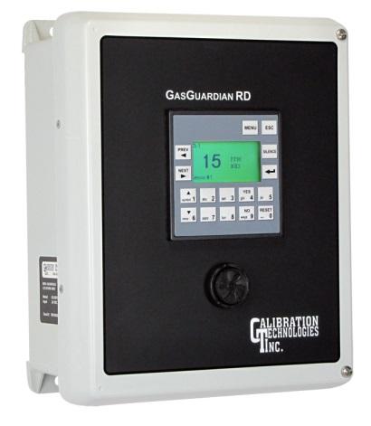
4 GasGuardian RD3 Operating and Installation Manual General Description The GasGuardian RD (GG-RD) is remote display slave module designed to accept data from the GasGuardian 6 (GG-6) master controller. It provides continuous real-time monitoring of each sensor via Modbus RTU protocol on RS-485 mirroring the GG-6 controller display. The backlit LCD display provides an at-a-glance status of gas concentrations and alarms. An 80 db buzzer on the front panel provides audible indication of any programmed event. The GG-RD is assembled into a wall mounted enclosure designed for nonclassified locations, and can be installed outdoors and washdown areas. The only output of this module is the door-mounted buzzer which can be silenced from the keypad on the front of the panel. Once the Modbus address is set, there are no user configurable settings on the GG-RD, as all other settings are configured on the GG-6 master controller. Installation Locating the GasGuardian RD An important consideration when installing the GG-RD is that it must be easily viewed and accessible for operating personnel. Installation Guidelines: Mount display on a solid surface with minimal vibration. Mount display thru the holes in the mounting flanges of the enclosure. Mount display in a general-purpose location only. Do not install in a hazardous environment. Mount display away from electromagnetic interference. Protect display from physical damage. Maximum distance from GG-6 controller is 1,000. The GG-RD is compatible with GG-6 controllers, version 4.00 and higher. Older version controllers can be field-upgraded. Contact Calibration Technologies for details. There are two versions of the GG-RD: GG-RD1 and GG-RD2. The GG-RD2 models are only used when more than one remote display is required, and are installed in between the GG-6 controller and the end-of-line GG-RD1. IMPORTANT: Factory default programming of the GG-6 master controller initiates the buzzer during any Warning, Alarm1, Alarm2 or Fault event. Since the GG-RD mimics the GG-6, any changes of the configuration will in turn change the operation of the GG-RD buzzer. Do not disable or overwrite default Actions #1 through #4 of the GG-6 to maintain correct buzzer operation on the GG-RD. 4


5 3GasGuardian RD Operating and Instruction Manual Wiring Electrical wiring must comply with all applicable codes. Wiring Guidelines: Always use insulated, stranded, shielded copper cable for all instrumentation cables. Do not pull communication wiring with AC power cables as this can cause electrical interference. Use only existing conduit holes for wiring connections if possible. Utilize included cable tie mounts to secure all cables and wires to the inside of enclosure door for strain-relief and slack for door movement. Communication Wiring: (at GG-6) It is recommended that RS-485 compliant cable be used, but if the total length of the wire run from GG-6 to the GG-RD1 is less than 1000, one pair of low-capacitive, shielded CAT5 (or better) cable can be used. Land (1) shield wire at GG-6 controller to earth ground (no connection at GG-RD). Terminate both ends of the cable into the supplied RJ11 Breakout Boards (BB), using only the #1 and #6 positions as shown in Figure 2 below. Note: GG-RD wiring shown on page 6 Power Wiring: 24Vdc and DC ground are sourced from GG-6 controller power supply ( drawing below). Use 18/2 stranded cable for distances up to 1,000 (Belden 9318 or equivalent). Top terminal block of GasGuardian RD operator interface (backside) #6 To V- (DC ground) power supply terminal of GG-6 To V+ (24Vdc) power supply terminal of GG-6 Figure 1. RJ11 Breakout Box GG-6 controller and GG-RD remote display communication wiring example Figure 2. #1 5
6 GasGuardian RD3 Operating and Installation Manual Communication Wiring (continued) A GG-6 can connect to one or many GG-RDs. For a single remote display Connect the GG-6 to a GG-RD1 as follows: For a multiple remote displays Connect the GG-6 to one or more GG-RD2s and a GG-RD1 as follows: Figure 3. Figure 4. Connect pin 1 on the GG-6 BB to pin 1 of the GG-RD1 BB. Connect pin 6 to pin 6. Use a Shielded Twisted Pair (STP) of wire to make the connection. It is recommended that RS-485 compliant cable be used, but if the total length of the wire run from GG-6 to the GG-RD1 is less than 1000, one pair of a shielded CAT5 (or better) cable can be used. Connect pin 1 on the GG-6 BB to pin 1 of the first GG-RD2 BB. Connect pin 6 to pin 6. Continue connecting pin 1 to pin 1 and pin 6 to pin 6 on each of the subsequent GG-RD2 s, ending with a GG-RD1. On all of the GG-RD2s, wire will have to be doubled up in the BBs. Twist shields together at all GG- RD2 s. Use STP to make the connection. It is recommended that RS-485 compliant cable be used, but if the total length of the wire run from GG-6 to the GG- RD1 is less than 1000, one pair of a shielded CAT5 (or better) cable can be used. 6
7 Operation Start-up Because of the distance between gas detection components, the test time required and accuracy of the response checks will be improved if two people perform the start-up procedures and use radio contact. Start-Up Test of the GasGuardian RD: 1) One person exposes each sensor to target gas. 2) The second person confirms that the remote display(s), when exposed to target gas, displays a proper change in value along with the correct room location or zone. 3) The onboard panel buzzer should activate during each event. The buzzer can be silenced by pressing the Silence button on the operator interface. The buzzer will then remain silent until the next event. 4) Pushing the silence or reset button on the GG-RD only silences or resets at the GG-RD. Operation Since the GG-RD is identical in operation to the GG-6 controller, refer to the GG-6 controller manual for operation details. Some of the sub-menus on the GG-RD are disabled. If the setting is disabled, message, will appear when the setting is selected. For single GG-RD1 remote display installation The GG-RD1 ID must match the ID on the GG-6 (typically 65) and must be configured as a Slave and a Remote before the GG-6 is configured. When the GG-6 is configured and saved, it pushes (via MODBUS) it's configuration to the GG-RD1. 3GasGuardian RD Operating and Instruction Manual For multiple remote display installation The GG-6 remote display configuration feature can only connect to one GG-RD at a time, but the GG-6 can be configured to broadcast to more than one GG- RD at once. When multiple GG-RD s are connected, the configurations take a few additional steps to synchronize all of the displays. Each GG-RD must have a unique Modbus address. By default, the GG-6 is set to 64 and the GG-RDs are set to 65. Configure the GG-6 Modbus as follows: MODBUS CONFIG Mode ID (64 to 127): 64 Master/Slave: Master Display: Main ID: 0 Assign each of the GG-RDs a new address in the range 65 to 127 (65, 66, 67, etc.). Configure the Modbus on the GG-RD as follows: MODBUS CONFIG Mode ID (64 to 127): 65, 66, 67, etc Master/Slave: Slave Display: Remote ID: same as ID On the GG-6, configure the Sensors, Groups, Actions, Relay and System. When the GG-6 is fully configured, exit and save the configuration. To push the configuration out to each of the GG-RDs, enter the Modbus Config Mode screen, set the ID to the address of the first GG-RD, exit and save. Wait for the first GG-RD to begin displaying the same info as the GG-6. This could take several minutes. Once the GG-RD begins displaying the same info as the GG-6, repeat for all of the other GG-RD addresses. 7
8 GasGuardian RD3 Operating and Installation Manual Multiple remote display installation (continued) Once all GG-RDs have been configured, re-enter the Modbus configuration screen, set the ID to 0 (broadcast mode), exit and save the configuration. Once these steps are complete, all of the remote displays should show the same information, and none of them should be showing a communication fault (a bold C in the upper left corner of the display). For example: If the system has four GG-RDs and they were numbered up above as 65, 66, 67 and 68. Enter the Modbus Config Mode screen, set the ID to 65, exit and save. Wait for the GG-RD to refresh. Repeat for 66, 67 and 68. Re-enter the Modbus Config Mode screen, return the ID to 0, exit and save. These steps must be repeated any time a configuration parameter is change in the GG-6. 8

9 3GasGuardian RD Operating and Instruction Manual LCD Operator Interface Key Functions: Below is a list of the common key functions used for the LCD operations: MENU ESC ENTER PREV NEXT YES/NO Alphanumeric Up/Down to enter main menu to go back to previous menu/sub-menu to modify the programming fields to go back to previous screen to advance to next screen when prompted and to accept configuration changes for menu selections and to enter values and text to navigate drop-down lists during configuration Operation Alternate System Display Screens Below are three alternate system display screens, depending on the number of expansion modules connected at the GG-6 controller. Inactive channels are displayed without a square. Action events (fault, warning or alarm) are displayed by a flashing solid black square next to channel number. Ch Sensor channels 1 through 11 active. System normal no action events. Ch1 Ch2 Ch POWERUP Ch4 0 Ch Ch Ch Sensor channels 1 through 22 active. Action event on channels 2 and 3. Ch Sensor channels 1 through 24 active. Action event on channel 14. 9
10 GasGuardian RD3 Operating and Installation Manual System display screens After system power-up, the normal operating screen will be displayed. It provides at-aglance system status, showing real-time gas concentrations. Warn, Alarm and Fault indications (W, A and F) will flash until the conditions are cleared. In the example screen on the right: Channel 1 gas concentration has exceeded the warn setpoint. Channel 2 has exceeded the warn and alarm setpoints. Channel 3 has been set to inactive; therefore, the channel is turned off. Channel 5 indicates a fault due to faulty wiring or a sensor signal less than 1 ma. A communication error is indicated by the letter C in the top left section of the display. C Ch1 28 W Ch2 162 WA Ch3 Ch4 Ch5 Ch F An over-range condition is indicated by flashing of the full-scale reading, followed by the message OVR. This also indicates that the sensor output is over 20 ma. Ch5 OVR % NH3 VENT LINE Alarm Warn PREV or NEXT to go to Channel View screens. MENU to go to main menu screen. Channel view Channel view shows only the status of the channel being viewed, along with room/zone location. Warn, Alarm and Fault indications will flash until the conditions are cleared. If the STEL-TWA function is set to Active, the real-time value is displayed, along with the time-weighted average values for the 15- minute short term exposure limit (STEL) and 8-hour time weighted average (TWA). Alarm conditions will also flash to indicate that those programmed values have been exceeded. Ch2 162 ENGINE ROOM PPM NH3 Alarm Warn Ch1 CONFIG Mode 76 PPM NH3 Alarm 32 PPM STEL Warn 9 PPM TWA Engine Room 10
11 3GasGuardian RD Operating and Instruction Manual Menu Tree 1) Alarm Log Ch2 162 ENGINE ROOM Alarm PPM Warn NH3 Ch5 % 0.00 NH3 Fault VENT LINE 2) Cal Mode Ch1 28 W Ch2 162 WA Ch3 0 Ch4 0 Ch Ch F 4) Config Mode 1) Sensors 3) Last Cal Menu 1) Alarm Log 2) Cal. Mode 3) Last Cal Date 4) Config Mode 5) Clock 6) Contrast 7) Relay Test 8) About CONFIG Menu Password: ) Groups CLOCK Date: 02/26/10 Time: 15:28:46 5) Clock Config Menu CONFIG Mode 1) Sensors 2) Groups 3) Actions 4) Relays 5) System 6) MODBUS 3) Actions Contrast ) Contrast 4) Relays 7) Relay Test 8) About Calibration Technologies, Inc. Specialists in Gas Detection Software Version: GG6 v2.00 5) System 6) Modbus MODBUS CONFIG Mode ID (64 to 127): 65 Master/Slave: Slave Display: Remote ID: 65 11
12 GasGuardian RD3 Operating and Installation Manual Maintenance All gas detection systems should be calibrated with certified calibration gas once every six months. At this interval, all alarm functions and outputs should be tested, verified and documented. Keep an operation log of all maintenance, calibrations and alarm events. To clean the controller, use a mild cleaning solution and soft cloth. Specifications Input Power Requirements: 24 VDC, 0.250A (21 Vdc to 27 Vdc) Dimensions: 11.3 high x 9.3 wide x 7 deep Weight: 5 lbs Enclosure: Fiberglass Reinforced Polyester NEMA 4X, IP 65, with neoprene gasket. Continuous stainless steel hinge. Captive screws in lid. For nonclassified areas. Temperature Range: 0 F to +122 F Humidity Range: 0-95% RH condensing (100% intermittent), with proper conduit seals. Wiring Connections: RS-485: RJ11 breakout board Power: Terminal block plug Terminal Block Plugs (Field Wiring): AWG, torque 4 lbs-in. Buzzer: 80 db, with volume attenuator shutter. Silenceable from keypad on front panel. User Interface: LCD illuminated screen. Graphic display screen: 128 x 64 pixels. 8 lines x 22 characters. Sealed membrane switches. 12
13 Limited Warranty & Limitation of Liability Calibration Technologies, Inc. (CTI) warrants this product to be free from defects in material and workmanship under normal use and service for a period of two years, beginning on the date of shipment to the buyer. This warranty extends only to the sale of new and unused products to the original buyer. CTI s warranty obligation is limited, at CTI s option, to refund of the purchase price, repair, or replacement of a defective product that is returned to a CTI authorized service center within the warranty period. In no event shall CTI s liability hereunder exceed the purchase price actually paid by the buyer for the Product. This warranty does not include: a) routine replacement of parts due to the normal wear and tear of the product arising from use; b) any product which in CTI s opinion, has been misused, altered, neglected or damaged by accident or abnormal conditions of operation, handling or use; c) any damage or defects attributable to repair of the product by any person other than an authorized dealer or contractor, or the installation of unapproved parts on the product The obligations set forth in this warranty are conditional on: a) proper storage, installation, calibration, use, maintenance and compliance with the product manual instructions and any other applicable recommendations of CTI; b) the buyer promptly notifying CTI of any defect and, if required, promptly making the product available for correction. No goods shall be returned to CTI until receipt by the buyer of shipping instructions from CTI; and c) the right of CTI to require that the buyer provide proof of purchase such as the original invoice, bill of sale or packing slip to establish that the product is within the warranty period. THE BUYER AGREES THAT THIS WARRANTY IS THE BUYER S SOLE AND EXCLUSIVE REMEDY AND IS IN LIEU OF ALL OTHER WARRANTIES, EXPRESS OR IMPLIED, INCLUDING BUT NOT LIMITED TO ANY IMPLIED WARRANTY OF MERCHANTABILITY OR FITNESS FOR A PARTICULAR PURPOSE. CTI SHALL NOT BE LIABLE FOR ANY SPECIAL, INDIRECT, INCIDENTAL OR CONSEQUENTIAL DAMAGES OR LOSSES, INCLUDING LOSS OF DATA, WHETHER ARISING FROM BREACH OF WARRANTY OR BASED ON CONTRACT, TORT OR RELIANCE OR ANY OTHER THEORY. 13
14
15

16 GG-RD
GG-6 MULTI-CHANNEL GAS DETECTION CONTROL PANEL. Installation and Operation Manual
 GG-6 MULTI-CHANNEL GAS DETECTION CONTROL PANEL Installation and Operation Manual 2 GG-6 Warning Use this product only in the manner described in this manual. If the equipment is used in a manner not specified
VP Process Inc. Model: VP-EC-RDU Modbus RTU LCD Display
 VP Process Inc. Model: Modbus RTU LCD Display User Manual Ver: 2.0 Aug. 2017 P a g e 1 Standard Features Low Power (12-24 VDC) 2.1 x 5mm Barrel Plug, RJ45 and Terminal Block Input On-Board Local Temperature
ControlKeeper 4. General Information. Connecting Relay Loads. Installation Sheet. Getting Started. Power Supply Wiring. Mounting the Cabinet
 General Information ControlKeeper 4 Installation Sheet Model# CK4-120NO- Model# CK4-277NO The ControlKeeper-4 model is shipped in one package and is configured with either a 120V or a 277V transformer.
AirTest Model CN9000 Series Sensor Controller
 AirTest Model CN9000 Series Sensor Controller AirTest Model CN9000 Series Sensor Controller THEORY OF OPERATION A basic CN9000 configuration consists of Input/Process/Display combination modules, a 3 relay
Model 206 Operating Instructions. Setra Systems, Inc. 159 Swanson Road, Boxborough, MA
 Model 206 Operating Instructions Setra Systems, Inc. 159 Swanson Road, Boxborough, MA 01719 800.257.3872 www.setra.com 1.0 General Information Every Model 206 has been tested and calibrated before shipment.
OZONE SWITCH Model OS-6. OS-6 Features
 USER MANUAL OZONE SWITCH Model OS-6 OS-6 Features The OS-6 is an industrial grade ozone controller and monitor. The OS-6 design is optimized for accuracy and ease of installation, setup and operation.
ES-600 Ozone Controller Operation Manual
 ES-600 Ozone Controller Operation Manual Questions about your product? Find answers here: Web: www.ozonesolutions.com/es-600 Phone: 712-439-6880 Ozone Solutions OZONE CONTROLLER Model ES-600 Instructions
HUBBCOM GSC3000/GSC4000 Flush-Mount Smart Controller Quick Installation Guide
 G A I - T R O N I C S C O R P O R A T I O N A H U B B E L L C O M P A N Y HUBBCOM GSC3000/GSC4000 Flush-Mount Smart Controller Quick Installation Guide Important Safety Instructions Read, follow, and retain
Carefree-Security. Installation and programming instructions 1050A. Owner s Manual
 Carefree-Security Heavy Duty Commercial - Industrial Fully Sealed Digital Access Keypad Specially Designed for Gate Operators, Overhead Doors, Specialty Doors & Electric Door Locking Devices SINGLE OR
TABLE OF CONTENTS INTRODUCTION. 3. Analog Input Analog Output Digital Input Digital Output OPERATIONAL DESCRIPITON.. 7 PROGRAMMING AND INITIAL SETUP.
 DIVERSIFIED HEAT TRANSFER SERIES 700 STEAM GENERATOR CONTROLLER INSTRUCTION MANUAL VISIT OUR WEBSITE AT SIGMACONTROLS.COM SERIES 700 DHT STEAM GENERATOR MANUAL 042514 2 TABLE OF CONTENTS INTRODUCTION.
VIP-812A DUAL NETWORKED STATION PORT
 ISSUE 1 VIP-812A DUAL NETWORKED STATION PORT INTRODUCTION The VIP-812A Dual Networked Station Port allows most loop start terminal devices to be connected to a managed IP-based LAN/WAN. SPECIFICATIONS
500 Business Center Drive Pittsburgh, PA USA CAGE 1BGJ7. SwitchMaster R5000 Series Ultra-Compact Ganged A/B Switching System
 Market Central www.secureswitch.com 500 Business Center Drive Pittsburgh, PA 15205 USA 412.494.2800 CAGE 1BGJ7 SwitchMaster R5000 Series Ultra-Compact Ganged A/B Switching System July, 2014 COMPLETE 2
LCI User Manual mantracourt.com
 LCI User Manual mantracourt.com LCI Load Cell Junction Box with Fault Monitor Contents Chapter 1 Introduction to the LCI... 2 Chapter 2 Installing the LCI... 3 Chapter 3 Setting up the LCI... 4 Sequence
DVI KVM. Extra Long Range Extender Over One CAT5. User Manual EXT-DVIKVM-ELR. Release A8
 DVI KVM Extra Long Range Extender Over One CAT5 EXT-DVIKVM-ELR User Manual Release A8 Important Safety Instructions 1 Read these instructions 2 Keep these instructions 3 Heed all warnings 4 Follow all
Eco Sensors OZONE CONTROLLER Model OS-6 Instructions for Use. General and New Features
 Eco Sensors OZONE CONTROLLER Model OS-6 Instructions for Use General and New Features The OS-6 is an industrial grade Ozone controller and monitor. The OS-6 design has been optimized for accuracy, ease
PSA200 User s Manual
 2011 Visionary Solutions, Inc. All rights reserved. Please visit the support section of our website at www.vsicam.com for manuals, other documentation, and software downloads. Visionary Solutions, Inc.
PRODUCT CONTENTS... 3 II. REQUIRED MATERIALS... 3 III. OVERVIEW... 3 IV. BENCH LAYOUT...
 IR-510 Bench 2012 Infrared Industries, Inc. 25590 Seaboard Lane Hayward, CA 94545 Toll-free phone 800.344.0321 Phone 510.782.8100 Fax 510.782.8101 www.infraredindustries.com Table of Contents I. PRODUCT
VE8014A/VE8014AR QUAD NETWORKED STATION PORT
 ISSUE 2 VE8014A/VE8014AR QUAD NETWORKED STATION PORT INTRODUCTION The VE8014A/VE8014AR Quad Networked Station Port allows most loop start terminal devices to be connected to a managed IP-based LAN/WAN.
AirPro Surveyor 2 Manual
 AirPro Surveyor 2 Manual AirPro Surveyor Specifications Table of Contents Size 3/8 x 7 1/2 x 4 3/8 Weight 4.6 lbs. 2094 g Dynamic Range 1-1000 ml/min. total flow/constant flow Flow Capacity (8 Hrs.) 1000
PCM-7140 Pulsed Current Source Operation Manual
 PCM-7140 Pulsed Current Source Operation Manual Directed Energy, Inc. 1609 Oakridge Dr., Suite 100, Fort Collins, CO 80525 (970) 493-1901 sales@ixyscolorado.com www.ixyscolorado.com Manual Document 7650-0031
Operating Bulletin MODBUS-RTU. The Fastest Flow Controller Company in the World!
 Operating Bulletin MODBUS-RTU The Fastest Flow Controller Company in the World! 1 Notice: Alicat Scientific, Inc. reserves the right to make any changes and improvements to the products described in this
Vocia ELD-1. Operation Manual
 Vocia Operation Manual Biamp Systems 9300 S.W. Gemini Drive, Beaverton, Oregon 97008 U.S.A. (503) 641-7287 www.biamp.com table of contents Vocia End of Line Device () features....3 setup and use...............................................................................
MODBUS MANUAL For the AccUView UV Transmission Monitor
 MODBUS MANUAL For the AccUView UV Transmission Monitor HF scientific, inc. 3170 Metro Parkway Ft. Myers, FL 33916 Phone: 239-337-2116 Fax: 239-332-7643 E-Mail: info@hfscientific.com Website: www.hfscientific.com
Instruction Sheet ICLS-COOL TM. Quiet-Cool Series Closet Cooler ICLS-COOL1 ICLS-COOL2
 Instruction Sheet ICLS-COOL TM Quiet-Cool Series Closet Cooler (REAR) (REAR) THANK YOU TM Thank you for purchasing the Quiet Cool Series ICLS-COOL Closet Cooler. Please read these instructions thoroughly
CO2 Controller Operating Instructions Models: RAD-0501, RAD-0501A, RAD-0501E 1. Product Description
 CO2 Controller Operating Instructions Models: RAD-0501, RAD-0501A, RAD-0501E 1. Product Description RAD-0501 Greenhouse Mode: Controls CO2 generator or regulator to increase CO2 levels during daylight
SATA II HDD Canister KISS DA 435 Quick Reference Guide
 SATA II HDD Canister KISS DA 435 Quick Reference Guide If it s embedded, it s Kontron 1. Table of Contents SATA II HDD Canister KISS DA 435 1. Table of Contents 1. Table of Contents... 1 2. Important Information...
Eco Sensors OZONE CONTROLLER Model OS-6 Instructions for Use. General and New Features
 Eco Sensors OZONE CONTROLLER Model OS-6 Instructions for Use General and New Features The OS-6 is an industrial grade Ozone controller and monitor. The OS-6 design has been optimized for accuracy, ease
OPERATIONS MANUAL PCM-I/O48
 OPERATIONS MANUAL PCM-I/O48 NOTE: This manual has been designed and created for use as part of the WinSystems Technical Manuals CD and/or the WinSystems website. If this manual or any portion of the manual
PIM-Mini Pulsed Current Source Operation Manual
 PIM-Mini Pulsed Current Source Operation Manual Directed Energy, Inc. 1609 Oakridge Dr., Suite 100, Fort Collins, CO 80525 (970) 493-1901 sales@ixyscolorado.com www.ixyscolorado.com Manual Document 7650-0007
LPG STM 94442A User s Manual
 1 LPG STM 94442A User s Manual This Manual belongs to: Company: 3 Table of Contents Features....... 4 Hardware Installation...5 Monitor Mounting Dimensions.....7 Monitor Specifications...8 Sender Specifications.....9
icp installation guide
 The Information Control Point (icp) is the latest SmartFarm Technology by Inc. The icp is the ultimate on-farm data-management tool. The icp has all the power of a basic personal computer, but instead
MYRIAD QLC 4-CHANNEL MONITOR/CONTROLLER INSTRUCTION MANUAL
 MYRIAD QLC 4-CHANNEL MONITOR/CONTROLLER INSTRUCTION MANUAL VISIT OUR WEBSITE SIGMACONTROLS.COM MYR QLC MANUAL 013114 2 TABLE OF CONTENTS INTRODUCTION 3 Ordering Information Specifications Features WIRING
Global Water globalw.com. Global Water. Instrumentation, Inc.
 Global Water Instrumentation, Inc. 151 Graham Road P.O. Box 9010 College Station, TX 77842-9010 T: 800-876-1172 Int l: (979) 690-5560, Fax: (979) 690-0440 E-mail : globalw@globalw.com PC300: Process Controller
MTX-A Temperature Gauge User Manual
 MTX-A Temperature Gauge User Manual 1. Installation... 2 1.1 Gauge Mounting... 2 1.2 Temperature Sensor Mounting... 2 1.2.1 Changing the MTX-A s Gauge Bezel... 2 1.3 Main Gauge Wiring... 3 1.3.1 Single
RAYMAPB. Power Supply and Terminal Box for Marathon MM/MR/FA/FR Sensors. Manual Addendum. Rev. A 06/
 RAYMAPB Power Supply and Terminal Box for Marathon MM/MR/FA/FR Sensors Manual Addendum Rev. A 06/2014 51001 Contacts Worldwide Headquarters Santa Cruz, CA USA Tel: +1 800 227 8074 (USA and Canada only)
Indoor/Outdoor Proximity Reader and Keypad with 10cm (4in) Read Range
 Read Range") Indoor/Outdoor Proximity Reader and Keypad with 10cm (4in) Read Range Stand alone CR-R885-SB Installation and Operating Instructions V1.1 TABLE OF CONTENTS Installation... 2 Mounting and Wiring... 2 Mounting
Indoor/Outdoor Proximity Reader and Keypad with 10cm (4in) Read Range Stand alone CR-R885-SB Installation and Operating Instructions V1.1 TABLE OF CONTENTS Installation... 2 Mounting and Wiring... 2 Mounting
SECURE/NONSECURE LED SIGN USER MANUAL
 SECURE/NONSECURE LED SIGN USER MANUAL December 2012 Wall Mount Part Number: 51-01198 1U Rack Mount Part Number: 51-01196 500 Business Center Drive, Pittsburgh, PA 15205 Phone: (412) 494-2800, Fax: (412)
User Manual rev: Made in Taiwan
 SP-1014 1x4 DVI Splitter over Single Cat.X with HDCP Support User Manual rev: 111209 Made in Taiwan The SP-1014 1x4 DVI Splitter over Single Cat.X with HDCP Support has been tested for conformance to safety
SP x4 DVI over Single CAT5 Distribution Amplifier. User Manual. Made in Taiwan
 SP-1014 1x4 DVI over Single CAT5 Distribution Amplifier User Manual Made in Taiwan Safety and Notice The SP-1014 1x4 DVI over Single CAT5 Distribution Amplifier has been tested for conformance to safety
User Manual rev: Made in Taiwan
 SP-5022V 1x2 HDMI Splitter/Repeater over Cat.X with HDBaseT-Lite, 4K2K & local Out User Manual rev: 140212 Made in Taiwan The SP-5022V 1x2 HDMI Splitter/Repeater over Cat.X with HDBaseT-Lite, 4K2K & local
Airborne Particle Counter
 985 Airborne Particle Counter Getting Started PN 4136462 March 2012 2012 Fluke Corporation. All rights reserved. Printed in U.S.A. Specifications are subject to change without notice. All product names
Industrial Ethernet Ethernet to Serial Gateways Ethernet to Serial Converters for Modbus, Red lion and other protocols
 USER MANUAL Industrial Ethernet Ethernet to Serial Gateways Ethernet to Serial Converters for Modbus, Red lion and other protocols Contents at a Glance: Section 1 General Information RM-PS-024-01F 3 Section
DP-222Q Color Video Door Phone Manual
 DP-222Q Color Video Door Phone Manual * has 6 LEDs for nighttime operation Remotely and securely talk to visitors and unlock doors, gates, etc. from the Easily connect a secondary * Simple 2-wire connection
Global Water Instrumentation, Inc.
 Instrumentation, Inc. 11390 Amalgam Way Gold River, CA 95670 T: 800-876-1172 Int l: (916) 638-3429, F: (916) 638-3270 Display: EZ100 11/12/04-1 - Congratulations on your purchase of the EZ100 Display.
OPERATING AND SERVICE MANUAL. Universal Interface Device 47
 OPERATING AND SERVICE MANUAL Universal Interface Device 47 MAGNA-POWER ELECTRONICS, INC. 39 ROYAL ROAD, FLEMINGTON, NJ 08822 May 24, 2012 SAFETY NOTICE Universal Interface Device 47 (UID46) connects
LCI Load Cell Junction Box with Fault Monitor
 LCI Load Cell Junction Box with Fault Monitor User Manual www.mantracourt.co.uk The LCI Load Cell Failure Alarm Manual Chapter 1 Introduction to the LCI...2 Chapter 2 Installing the LCI...3 Figure 2.1
DCM Digital Control Modules
 DCM Digital Control Modules TECHNICAL MANUAL Version 1.2 November 2011 Safety Precautions Caution Read Instructions: Read and understand all safety and operating instructions before using the equipment.
4300 WINDFERN RD #100 - HOUSTON TX VOICE (713) FAX (713) web: IMPORTANT!!!
 FAX (713) web: IMPORTANT!!!") 4300 WINDFERN RD #100 - HOUSTON TX 77041-8943 VOICE (713) 973-6905 - FAX (713) 973-9352 web: www.twrlighting.com IMPORTANT!!! PLEASE TAKE THE TIME TO FILL OUT THIS FORM COMPLETELY. FILE IT IN A SAFE PLACE.
4300 WINDFERN RD #100 - HOUSTON TX 77041-8943 VOICE (713) 973-6905 - FAX (713) 973-9352 web: www.twrlighting.com IMPORTANT!!! PLEASE TAKE THE TIME TO FILL OUT THIS FORM COMPLETELY. FILE IT IN A SAFE PLACE.
PixController, Inc. Wireless Switch Sensor For Normally Open (NO) and Normally Closed (NC) Sensors
 and Normally Closed (NC) Sensors") PixController, Inc. Wireless Switch Sensor For Normally Open (NO) and Normally Closed (NC) Sensors Model: SEN-410 User s Manual Version 1.00 WARRANTY REGISTRATION PixController, Inc. warrants products
PixController, Inc. Wireless Switch Sensor For Normally Open (NO) and Normally Closed (NC) Sensors Model: SEN-410 User s Manual Version 1.00 WARRANTY REGISTRATION PixController, Inc. warrants products
DVI ELR Extender over one CAT5
 DVI ELR Extender over one CAT5 EXT-DVI-1CAT5-ELR User Manual Important Safety Instructions 1 Read these instructions 2 Keep these instructions 3 Heed all warnings 4 Follow all instructions 5 Do not use
DP-222Q Color Video Door Phone Manual
 DP-222Q Color Video Door Phone Manual * has 6 LEDs for nighttime operation Remotely and securely talk to visitors and unlock doors, gates, etc. from the Easily connect an secondary * Simple 2-wire connection
IRB-RET O P E R A T I N G I N S T R U C T I O N S UNIVERSAL SAFETY RETROREFLECTIVE PHOTOEYE U L MONITORED DEVICE
 O P E R A T I N G I N S T R U C T I O N S IRB-RET UNIVERSAL SAFETY RETROREFLECTIVE PHOTOEYE U L 3 2 5-2 0 1 6 MONITORED DEVICE 4564 Johnston Parkway, Cleveland, Ohio 44128 P. 800 426 9912 F. 216 518 9884
What s in the box. SUP paddle sensor. Paddle sensor mounting track. Charger. USB cable. In your Motionize SUP kit you will find:
 User's Manual 1 What s in the box In your Motionize SUP kit you will find: SUP paddle sensor Paddle sensor mounting track Charger USB cable 2 Android & ios Requirements Android 5 or newer. iphone 5 or
WR-5e Remote Control
 1. Introduction WR-5e Remote Control The WR-5e is a microprocessor based serial data remote control unit for Ashly NE or NX products. Compatible products currently include Pema amplifiers, ne8800 and ne4800
Digital Electronic Lock OWNER S MANUAL
 CAL-ROYAL CR3000 Digital Electronic Lock OWNER S MANUAL THANK YOU for purchasing CAL-ROYAL CR 3000 Digital Lock. Your new CAL-ROYAL CR3000 Digital Lock advanced features include: 1 Master Code for entry
Tempco Instruction Manual
 Tempco Instruction Manual 1/16 DIN Solid State Temperature Controller Relay Output Solid State Output For Heating Model Numbers: TEC-901, TEC-902, TEC-905 Temperature controls in this series are designed
VIP-804 QUAD ENHANCED NETWORK AUDIO PORT
 ISSUE 6 VIP-804 QUAD ENHANCED NETWORK AUDIO PORT INTRODUCTION The VIP-804 Quad Enhanced Network Audio Port enables voice access to four zones of one-way paging over an IP network, allowing page zones to
HDMI to 3GSDI Converter
 HDMI to 3GSDI Converter EXT-HD-3G-C User Manual Release A2 Important Safety Instructions 1. Read these instructions. 2. Keep these instructions. 3. Heed all warnings. 4. Follow all instructions. 5. Do
TiR2, TiR3, TiR4. Getting Started Guide. IR FlexCam Thermal Imager
 TiR2, TiR3, TiR4 IR FlexCam Thermal Imager PN 2670659 May 2006 2006 Fluke Corporation, All rights reserved. Printed in USA All product names are trademarks of their respective companies. LIMITED WARRANTY
CTI 3570A SERIES INDUSTRIAL ETHERNET SWITCH INSTALLATION AND OPERATION GUIDE Version 1.2
 CTI 3570A SERIES INDUSTRIAL ETHERNET SWITCH INSTALLATION AND OPERATION GUIDE Version 1.2 CTI Part # 062-00355-012 3570AIOG 033104 $25 i Copyright 2004 Control Technology Inc. All rights reserved. This
4300 WINDFERN RD #100 HOUSTON TX VOICE (713) FAX (713) web: IMPORTANT!!!
 FAX (713) web: IMPORTANT!!!") 4300 WINDFERN RD #100 HOUSTON TX 77041-8943 VOICE (713) 973-6905 FAX (713) 973-9352 web: www.twrlighting.com IMPORTANT!!! PLEASE TAKE THE TIME TO FILL OUT THIS FORM COMPLETELY. FILE IT IN A SAFE PLACE.
4300 WINDFERN RD #100 HOUSTON TX 77041-8943 VOICE (713) 973-6905 FAX (713) 973-9352 web: www.twrlighting.com IMPORTANT!!! PLEASE TAKE THE TIME TO FILL OUT THIS FORM COMPLETELY. FILE IT IN A SAFE PLACE.
zpen-1080p Features zpen-1080p Layout
 1 zpen-1080p Features CMOS image sensor with Low Light sensitivity HD 1080P up to 30fps, 720P up to 60fps H.264 compression Built-in micro SD card, supports up to 32GB One button operation Easily download
HD-SDI Vandal Dome Camera
 HD-SDI Vandal Dome Camera DWC-HF21M4TIR ABOUT MANUAL Before installing and using the camera, please read this manual carefully. Be sure to keep it handy for future reference. 12112013 PRECAUTIONS Do not
1x4 HDMI & Full 3D support over Single CAT5 Distribution Amplifier with Local Output. User Manual
 SP-5105KC 1x4 HDMI & Full 3D support over Single CAT5 Distribution Amplifier with Local Output User Manual To avoid EMI issue, complete STP Cat6 cable is strongly recommended! rev: 131028 Made in Taiwan
SoniChek MC. 99 Washington Street Melrose, MA Phone Toll Free TRIPLETT. Mini Sound Level Meter C Weighted
 99 Washington Street Melrose, MA 02176 Phone 781-665-1400 Toll Free 1-800-517-8431 TRIPLETT SoniChek MC Mini Sound Level Meter C Weighted Instruction Manual 84-888 4-10 Visit us at www. I. Safety information
Model OI x22 ProSafe
 Model OI-7420 4x22 ProSafe Operation Manual Revision 2.0w Product Overview The Otis Instruments, Inc. GenII ProSafe 4x22 Model OI-7420 is a two channel gas monitor that functions as a transmission controller.
COBALT C INSTALLATION GUIDE RFID CONTROLLER ESCORT MEMORY SYSTEMS. High Frequency Passive Radio Frequency Identification Controller
 ESCORT MEMORY SYSTEMS COBALT C0405-232-01 RFID CONTROLLER High Frequency Passive Radio Frequency Identification Controller INSTALLATION GUIDE How to Install and Configure Escort Memory Systems Cobalt C0405-232-01
MYRIAD LC1 LEVEL CONTROLLER INSTRUCTION MANUAL
 MYRIAD LC1 LEVEL CONTROLLER INSTRUCTION MANUAL VISIT OUR WEBSITE SIGMACONTROLS.COM MYR LC1 MANUAL 062114 TABLE OF CONTENTS INTRODUCTION 3 Ordering Information Specifications Features Dimensions WIRING
USB 2.0 Ranger Port USB m CAT 5e/6/7 Extender System. User Guide
 USB 2.0 Ranger 2304 4-Port USB 2.0 100m CAT 5e/6/7 Extender System User Guide Thank you for purchasing the USB 2.0 Ranger 2304. Please read this guide thoroughly. This document applies to Part Numbers:
CQM1 I/O Terminal Block Conversion Adapter. Easy and secure replacement by reusing the I/O terminal block wiring.
 CQM1 I/O CSM_CJ1W-AT4 DS_E_1_1 Easy and secure replacement by reusing the I/O terminal block wiring You can replace CQM1(H) Series with CJ Series, efficiently using your assets. Time for wiring works and
RSTC1000 HMI/PLC Design Guide WEB CONTROL PRODUCTS. User Manual FORM NO. L B MTY (81)
") WEB CONTROL PRODUCTS User Manual RSTC1000 HMI/PLC Design Guide DANGER Read this manual carefully before installation and operation. Follow Nexen s instructions and integrate this unit into your system
WEB CONTROL PRODUCTS User Manual RSTC1000 HMI/PLC Design Guide DANGER Read this manual carefully before installation and operation. Follow Nexen s instructions and integrate this unit into your system
DC425 NEMA 4X Analog Output Transducers
 User User Manual Manual DC425 NEMA 4X Analog Output Transducers ADV ANC ED MIC RO CON T RO L S INC. Manual #: 940-0D030 DC425 Description Offering a 4-20 ma output over single or multiple turns, the DC425
3-4 SAS/SATA II HDD Canister Entry version USER S MANUAL XC-34D1-SA10-0-R. Document number: MAN A
 3-4 SAS/SATA II HDD Canister Entry version XC-34D1-SA10-0-R USER S MANUAL Document number: MAN-00077-A ii Preface Important Information Warranty Our product is warranted against defects in materials and
Section 1 Introduction
 Section 1 Introduction The AT90ICEPRO is a real time In-Circuit Emulator (ICE) for all AT90S1200, -S2313, -S2323, -S2333, -S2343, -S4414, -S4433, -S4434, -S8515 and -S8535 devices. It can be upgraded to
1X2 HDMI Splitter with 3D Support
 AV Connectivity, Distribution And Beyond... VIDEO WALLS VIDEO PROCESSORS VIDEO MATRIX SWITCHES EXTENDERS SPLITTERS WIRELESS CABLES & ACCESSORIES 1X2 HDMI Splitter with 3D Support Model #: SPLIT-HDM3D-2
PIXIM Micro Dome Camera
 PIXIM Micro Dome Camera DWC-MC355T ABOUT MANUAL Before installing and using the camera, please read this manual carefully. Be sure to keep it handy for future reference. 07132012 PRECAUTIONS Do not open
MTX-A, Fuel Pressure Gauge PSI
 MTX-A, Fuel Pressure Gauge 0-100 PSI Contents 1 Mounting and Sensor Installation... 2 1.1 Gauge Mounting... 2 1.1.1 Changing the MTX-A s Gauge Bezel... 2 1.2 Fuel Pressure Sensor... 2 2 Wiring... 3 2.1
MWC-8. Operation MWC-8 800MHz Controller Manual. Operation Manual. manmwc9.
 MWC-8 Operation MWC-8 800MHz Controller Manual Operation Manual manmwc9 www.myeclubtv.com 1 CONTENTS Specifications. 3 Controller Orientation (Front / Rear) 4 Keypad Key Identification. 5 Main Features
Proliphix EPA-60 Installation Guide
 Proliphix EPA-60 Installation Guide Rev 1.2 Page 2 of 5 Installation CAUTION THE EPA-60 SHOULD ONLY BE POWERED WITH THE PROLIPHIX POWER SUPPLY INCLUDED WITH THE EPA-60. DO NOT POWER THE EPA-60 WITH ANY
Indoor Dome Camera DWC-D6351D DWC-D6351DB
 Indoor Dome Camera DWC-D6351D DWC-D6351DB ABOUT MANUAL Before installing and using the camera, please read this manual carefully. Be sure to keep it handy for future reference. 10252013 PRECAUTIONS Do
MPP200 User s Manual
 2011 Visionary Solutions, Inc. All rights reserved. Please visit the support section of our website at www.vsicam.com for manuals, other documentation, and software downloads. Visionary Solutions, Inc.
User's Guide. Model High Precision Quad Output DC Power Supply
 User's Guide Model 382270 High Precision Quad Output DC Power Supply Introduction Congratulations on your purchase of the Extech 382270 DC Power Supply. The Model 382270 can be used for many applications
OPERATING AND SERVICE MANUAL. Universal Interface Device 47
 OPERATING AND SERVICE MANUAL Universal Interface Device 47 MAGNA-POWER ELECTRONICS, INC. 39 ROYAL ROAD, FLEMINGTON, NJ 08822 May 24, 202 SAFETY NOTICE Universal Interface Device 47 (UID47) connects two
NOTE: The F2 button and the 4 LED annunciators do not function on the LD-ACF-I. To use these features, ask about the LD-ACF-R4/R4A.
 Large display AC frequency indicator The is a sophisticated microprocessorbased indicator designed specifically to monitor AC frequency. Intuitive scrolling text menus, (activated from the front panel),
EDG Port Industrial 10/100 Mbps Ethernet Switch. User Manual
 EDG-6528 8-Port Industrial 10/100 Mbps Ethernet Switch User Manual Copyright The documentation and the software included with this product are copyrighted 2005 by Advantech Co., Ltd. All rights are reserved.
Multi-Point Gas Detection and Control System
 Multi-Point Gas Detection and Control System DESCRIPTION Wall mounted, microprocessor-based, multi-point, analog electronic control system for various gas, temperature and humidity detection, control and
GF-1. Introduction. 1 Features. +-10G Tilt Compensated dual range aviation G-force meter. Operating Manual English 1.00
 GF-1 +-10G Tilt Compensated dual range aviation G-force meter Operating Manual English 1.00 Introduction The GF-1 is a 2.25 G-force meter capable of measuring G-forces exerted in an aircraft up to +-10G.
Proximity Card and Pin Reader Installation Manual
 Multi Prox Proximity Card and Pin Reader Installation Manual PUBLICATION INFORMATION 60A9 - Draft Release Version 0.1.2 71D0 - Version 1.0.5 CONTENTS Introduction... 1 Legend... 2 Terminology... 2 Mounting...
OPERATIONS MANUAL PCM-DOC
 OPERATIONS MANUAL PCM-DOC NOTE: This manual has been designed and created for use as part of the WinSystems Technical Manuals CD and/or the WinSystems website. If this manual or any portion of the manual
The IQ300 wall mount load cell indicator is a precision digital indicator for load cell and strain gauge applications.
 IQ300 Wall Mount Load Cell Indicator Data sheet English 1.01 Introduction The IQ300 wall mount load cell indicator is a precision digital indicator for load cell and strain gauge applications. The high
Operating Instructions
 Model No.: VH0101 Operating Instructions Thanks for purchasing our product. Please be sure to read this instruction manual carefully before using our product. Introduction VH0101 is a VGA video converter.
TC1880 Series. 4/5/6/8 Channel RS-232 FIBER OPTIC MICRO MUX User's Manual
 Series 4/5/6/8 Channel RS-232 FIBER OPTIC MICRO MUX MODEL: S/N: DATE: Notice! Although every effort has been made to insure that this manual is current and accurate as of date of publication, no guarantee
Ashly WR-5 Remote Control
 1. Introduction Ashly WR-5 Remote Control The WR-5 is a microprocessor based serial data remote control unit for Ashly NE or NX products. Compatible products currently include Pema amplifiers, ne8800 and
MICRO GROW GREENHOUSE SYSTEMS, INC
 MICRO GROW GREENHOUSE SYSTEMS, INC 4065 ZEVO DR., UNIT B-, TEMECULA, CA 9590 PHONE (95) 96-3340 FAX (95) 96-3350 www.microgrow.com Revision., -09-0 Growstat Control Series INSTALLATION PROCEDURES SERIES
DP-234Q (NTSC) DP-734Q (PAL) Hands-Free Video Door Phone Manual
 DP-734Q (PAL) Hands-Free Video Door Phone Manual") DP-234Q (NTSC) DP-734Q (PAL) Hands-Free Video Door Phone Manual Screen image simulated. * has four LEDs for nighttime operation Remotely and securely talk to visitors and unlock doors, gates, etc. from
DP-234Q (NTSC) DP-734Q (PAL) Hands-Free Video Door Phone Manual Screen image simulated. * has four LEDs for nighttime operation Remotely and securely talk to visitors and unlock doors, gates, etc. from
Table of Contents. User Manual. DS-201 Solar Web Monitor
 Table of Contents User Manual DS-201 Solar Web Monitor Installation.... 1 Step 1 Unpack and identify all Cables Step 2 Verify Serial Communication Setup Step 3 Plug in Communications Cable to Controller
EASON TECHNOLOGY. IO8 & IO24 Break-Out Module
 EASON TECHNOLOGY IO8 & IO24 Break-Out Module p/n 50-00180-01 Revision1.2 Eason Technology, Inc. 7975 Cameron Dr. Bldg 300 Windsor, CA 95492 Phone (707) 837-0120 FAX (707) 837-2742 http://www.eason.com
Product Documentation
 Product Documentation Emanate PowerPath TM TempTag PPT-300 Date: April 12, 2016 Document Number: PPT200-001 R1.4 Emanate Wireless, Inc. 11145 Windsor Rd. Ijamsville, MD 21754 Telephone: 844-EMANATE Email:
PixController, Inc. Wireless Magnetic Switch Sensor For Doors, Windows, and Gates
 PixController, Inc. Wireless Magnetic Switch Sensor For Doors, Windows, and Gates Model: SEN-420 User s Manual Version 1.00 WARRANTY REGISTRATION PixController, Inc. warrants products sold by it and guarantees
E2EY. A Proximity Sensor for Aluminum, Brass and Other Non-ferrous Metals. Iron Is Not Detected. Aluminum-detecting Proximity Sensor
 Aluminum-detecting Proximity Sensor EEY CSM_EEY_DS_E_5_1 A Proximity Sensor for Aluminum, Brass and Other Non-ferrous Metals. Iron Is Not Detected. Non-ferrous metals, such as aluminum and brass, are detected.