E-Series Troubleshooting Guide
|
|
|
- Bertina Briggs
- 5 years ago
- Views:
Transcription

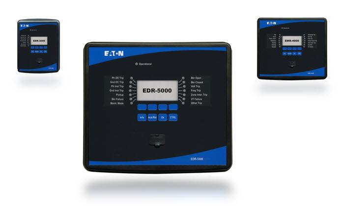
1 E-Series Troubleshooting Guide
2 Contents Troubleshooting by means of the System-OK-LED status... 5 Troubleshooting Hardware Troubleshooting Operation of the Device Troubleshooting Parameter Settings Troubleshooting Protection and Control Troubleshooting Communication Troubleshooting Recorder
3 Troubleshooting by means of the System-OK-LED status System LED Device Status Potential Error Cause Corrective Action off (not illuminated) Other LEDs are also off. Either no supply voltage or the power supply is faulty. Please check the supply voltage. If it is OK, send the device to be repaired. undefined, Other LEDs are showing a random The CPU board is faulty. Send the device to be repaired. not flashing pattern. constant red or flashing red The HMI shows an error number. Fatal system error Get in contact with the manufacturer. The Service-Team will provide a tool for error analysis. flashing green, switch to constant green within 30 seconds No error. The device is in its start-up phase. When the System LED switches to constant green, the protection functions are active. No action necessary. 5
4 System LED Device Status Potential Error Cause Corrective Action flashing red/ green The device is up and running. The The internal self-supervision module Check the cause of the last reboot under <Operation/ protection functions are working. has detected a serious problem in the Status display/ Sys/ Reboot>: system. The issue will be recorded Reboot=11: Your device suffered a short-term sag within an integrated fault memory. or outage of the supply voltage. Please check your power supply. You can quit the System LED by selecting <Operation/ Acknowledge/ SSV.Ack System LED>. Otherwise get in contact with our service-team. Provide us the information about unscheduled device reboots (<Operation/ Self Supervision/ System Error/ Resets by Device>). You will be supplied with a tool for error analysis. constant green The device s HMI is not operable. The device is starting up. The Check if the following action makes the device s HMI There are no Softkeys shown on the protection functions are already operable: panel. Instead the panel shows working, but the HMI is still starting up. Unplug the Ethernet (Connector X100). Is the HMI now Startup or just the device type (e.g. If this is not finished after 5 minutes, operable, there is an error on your Ethernet network (e.g. EDR-5000) without any Softkeys. the device is probably busy with an Ethernet storm). Please check your network traffic. handling Ethernet packets (Connector X100). 7
5 System LED Device Status Potential Error Cause Corrective Action The HMI is not operable. A normal page of the HMI is visible: Either there are Softkeys visible or the LED status page is being displayed. The HMI is not operable. A normal page of the HMI is visible: Either there are Softkeys visible or the LED status page is being displayed. There is no Ethernet connector (Connector X100). The HMI is operable. The device is busy with handling Ethernet packets (Connector X100). The protection functions are working. Some of the device s system parts are not working. The protection functions are working. The device is ready for operation and protects your electrical equipment. If you have the impression that the relay is not working correctly or you have any problems with setting its parameters, please look-up the next tables. Unplug the Ethernet (Connector X100). Is the HMI now operable, there is an error on your Ethernet network (e.g. an Ethernet storm). Please check your network traffic. Should this action not change the device s behavior, please read the next entry of this table. Leave the device connected to the supply voltage. Get in contact with our service-team. You will be supplied with a tool for error analysis. Look-up the next tables. 9
6 Troubleshooting Hardware Failure of the display Failure of a relay output (Also refer to: relay outputs do not react ) After selecting any key, the whole display remains dark or the display is defective. The physical status does not match the reported state. Check the reported state of the relay output with the HMI or PowerPort-E. Check the following issues: Is the supply voltage connected? This is the case when the System-LED is illuminated Is the environmental temperature within the allowed range? Try to adjust the contrast of the display by using PowerPort-E (increase/ decrease). If these checks do not show any results, send the relay back to the manufacturer. Check the following issues: Is the relay output in the latched state? Acknowledge the state if necessary. Is <Inverting> parameter of the relay output set? Check the wiring. Unplug the wiring from the relay output and measure its output. Set the state of the relay output by using the test functions Force/Disarm. If these checks do not show any results, send the relay back to the manufacturer. 11
7 Failure of a digital input Wrong setting of the device s clock after a shortage of the supply voltage Failure of a key The physical status of a digital input does not match its reported state. Check the reported state of the digital input with the HMI or PowerPort-E. The internal battery for powering the clock is empty or defect. Check the following issues: Is the configured voltage level set correctly? Is the voltage level of the digital input (signal level) correct? Is the parameter <Inverting> set? Check the wiring. If these checks do not show any results, send the relay back to the manufacturer. The relay is also working properly with an empty clock battery. The device s time can be synchronized. Please contact the service team. Send the relay back to the manufacturer. 13
8 Troubleshooting Operation of the Device Relay outputs or LEDs are in unexpected state. A trip shall be acknowledged without a password. What is the default password? How do I reset the password? A relay output or an LED has been reconfigured from latched to unlatched. Now you need to acknowledge the status once, if it was already pending before the reconfiguration. Acknowledge the LEDs and relay outputs. Set the password for <Password Level 0> to empty input. Now you do not have to enter any password for changes and acknowledges on security level 0. The factory-provided default password for all security levels is Refer to the chapter forgotten password of the user manual. 15
9 Troubleshooting Parameter Settings Transfer of device parameters from one protection device to another of the same type (e.g. EDR-5000). You have configured the parameters of a E- Series device. Now you want to transfer these parameters to another relay. This is possible, if both relays are of the same type, e.g. EDR Download the device parameters with PowerPort-E from the first relay. Save them into a file. Now reopen this file with PowerPort-E. Adapt the settings to the order code of the second device <Edit/ Modify Device Configuration (Typecode)...>. Select <Apply>. By this the existing parameter file is being converted to the format of the second device. Now there may be implausible parameters. They are marked with a question mark. These are not valid for this device type. Please adapt the values of these implausible parameters. Afterward you can transfer the parameter settings to the second device. 17
10 Troubleshooting Protection and Control After first start-up of the protective device there is a pending trip. The switchgears can not be operated by SCADA communication. Current and Voltage measurement Two red LEDs are illuminated at the front of the HMI. They indicate a trip and an alarm. The measured values of current and voltage have a big fluctuation. With the factory default settings the protection relay is configured with an undervoltage protection. Adapt the settings of the undervoltage protection or remove this module from the device project settings (if you do not need it). If you have any problems with acknowledging the pending alarm, please refer to Failure of a relay output. Set the switching authority of the device to remote. Adjust the field parameters general settings to the connected grid frequency (50Hz or 60Hz). 19
11 Relay outputs do not react. The contacts of the relay outputs do not open or close. This can be checked by simulating a fault and checking the relay output contacts with measurement equipment. Check the following issues: Acknowledge the relay outputs, if applicable. Is the status of the relay output forced to a dedicated value? (The relay output can be overwritten for commissioning purpose, refer to <Service/ Test>.) Is the correct parameter set active (1..4)? Is the required protection function active? Is overall protection active? Are the field parameters set correctly (CT ratio etc.)? Are the protection parameters set correctly (trip value, trip time)? Is the assigned protection function blocked? Is the protection function s trip signal routed to the Trip-Manager of the correct switchgear? Is the trip signal of the switchgear routed to the correct relay output? Is the wiring correct? 21
12 Failure of control from local or remote You can not switch locally or remotely. Check the following issues: Is the switch command blocked? Is the wiring correct? Do you have switching authority? Check the value of switching authority ( local or remote ). Is switching blocked by the synchro-check? 23
13 Troubleshooting Communication Failure of time synchronization. Failure of the TCP/IP connection. Check the following issues: Is the correct protocol for time synchronization selected (<Device Para/ Time / TimeSync>)? Is the timezone set correctly? Open the status page of the used protocol. Check, if the module works correctly. IRIGB: Is the correct type (IRIGB-00x) selected? SNTP: Is the IP address of a valid NTP Server configured? Check the following issues with your local IT: Does the device answer a ping request? If the device and the PC are part of the same the same subnet, gateway and subnet mask have to be set correctly within the device (<Device Para/ TCP/IP/ TCP/IP Config>). Is network communication blocked by a firewall? 25
14 Failure of USB connection. It is not possible to connect PowerPort-E, Field Device Installer or some other application to the relay via USB. The corresponding USB port (e.g. COM 5) can not be selected or connected by the application. Check the following issues: PowerPort-E: Have you installed release 3.60 or higher? Is the USB port of the PC still occupied by another application (program/application)? Close those applications. Is the protective device within the correct state? For a PowerPort-E connection the protective device has to be started up. For a connection with the Field Device Installer the protective device has to be within a different state. Refer to the Field Device Installers user manual. Unplug the USB cable from the protective device and plug it in again. After 10 seconds try again to connect PowerPort-E (or Field Device Installer) to the relay. Restart your PC. 27
15 Older protective devices with RS232: PowerPort-E does not connect via RS232. It is not possible to establish a connection with PowerPort-E from a PC to the device via RS232. Use a PowerPort-E version release 3.41 or higher. Starting from this release PowerPort-E supports a simplified creation of a serial connection. If your PC does not have a serial port, you need a USB-toserial-adapter that has been approved by Eaton. This has to be installed correctly. PowerPort-E can not connect to the device. This has been possible before by using the same PC. A connection between PowerPort-E and device has been possible before using the same PC. Now it is not possible to connect to the device. Verify that your cable is a zero-modem cable (please refer to the corresponding chapter). A simple serial cable does not have any flow control lines. A connection is only possible with a zero-modem cable. Check the following issues: Are the connection settings of PowerPort-E correct (refer to <Settings/ Device Connection...>)? In case of Ethernet (TCP) connection: Is the correct IP address selected? Check the wiring between PC and device. In case of Ethernet (TCP) connections: Is the TCP/IP connection working? Refer to Failure of the TCP/IP connection. Wait for 15 minutes and then try again to connect to the device. Restart your PC and then try again to connect to the device. 29
16 No communication (data transfer) with PowerPort-E possible, even though a connection has been established. Port is being blocked by a firewall. Check the settings of your firewall. You may require to unblock port
17 Troubleshooting Recorder The Event Recorder is permanently logging new events. The Waveform Recorder is permanently creating new records. The Event Recorder does permanently show new events (<Operation/ Recorders / Event rec>). To observe this phenomenon in PowerPort- E, please execute a refresh (F5 or Ctrl+F5). The Waveform Recorder shows a high number of created disturbance records. This number is growing steadily over time (<Operation/ Recorders / Waveform rec>). To observe this phenomenon in PowerPort- E, please execute a refresh (F5 or Ctrl+F5). Proceed as follows: 1. Look inside the Event Recorder which protection function is creating the events. 2. Check the settings of this protection function. Adapt them, if necessary. Example: Protection function df/dt (ROCOF) is configured too sensitive and is creating alarms with high frequency. Change the settings of this function. Check the following issues: 1. Check which events are configured to trigger the Waveform Recorder (<Device Para/ Recorders / Waveform rec>), e.g. Protection Alarm. 2. Check within the Event Recorder, which protection function creates the trigger (<Operation/ Recorders / Event rec>). 3. Check the settings of this protection function. Adapt them, if necessary. Example: Protection function df/dt (ROCOF) is configured too sensitive and is creating alarms with high frequency. Change the settings of this function. Alternatively you can also change the trigger source of the Waveform Recorder. But this is less advisable. 33
18 Instruction Leaflet MN026003EN Effective This instruction leaflet is published solely for information purposes and should not be considered all-inclusive. If further information is required, you should consult an authorized Eaton sales representative. The sale of the product shown in this literature is subject to the terms and conditions outlined in appropriate Eaton selling policies or other contractual agreement between the parties. This literature is not intended to and does not enlarge or add to any such contract. The sole source governing the rights and remedies of any purchaser of this equipment is the contract between the purchaser and Eaton. NO WARRANTIES, EXPRESSED OR IMPLIED, INCLUDING WARRANTIES OF FITNESS FOR A PARTICULAR PURPOSE OR MERCHANTABILITY, OR WARRANTIES ARISING FROM COURSE OF DEALING OR USAGE OF TRADE, ARE MADE REGARDING THE INFORMATION, RECOMMENDATIONS, AND DESCRIPTIONS CONTAINED HEREIN. In no event will Eaton be responsible to the purchaser or user in contract, in tort (including negligence), strict liability or otherwise for any special, indirect, incidental or consequential damage or loss whatsoever, including but not limited to damage or loss of use of equipment, plant or power system, cost of capital, loss of power, additional expenses in the use of existing power facilities, or claims against the purchaser or user by its customers resulting from the use of the information, recommendations and description contained herein. Eaton Electrical Sector 1000 Eaton Boulevard Cleveland, OH United States 877-ETN-CARE ( ) Eaton.com 2015 Eaton Corporation All Rights Reserved Printed in USA Eaton is a registered trademark All other trademarks are property of their respective owners.
HighPROTEC Troubleshooting Guide
 HighPROTEC Troubleshooting Guide HighPROTEC Troubleshooting Guide Contents HighPROTEC Troubleshooting Guide... 2 Troubleshooting by means of the System-OK-LED status... 3 Troubleshooting Hardware... 6
HighPROTEC Troubleshooting Guide
 HighPROTEC Troubleshooting Guide HighPROTEC Troubleshooting Guide Contents HighPROTEC Troubleshooting Guide... 2 Self-supervision Messages... 3 Troubleshooting by means of the System-OK-LED status... 5
Power Xpert Meter 2000 Series
 Quick Start Guide IM02601002E Effective April 2017 PXM 2250 PXM 2260 PXM 2270 PXM 2280 PXM 2290 Power Xpert Meter 2000 Series Contents Description Page Mechanical Installation... 1 Electrical Wiring....
LP800 Loop Tester. Installation and Operation Manual
 LP800 Loop Tester Installation and Operation Manual DISCLAIMER OF WARRANTIES AND LIMITATION OF LIABILITY The information, recommendations, descriptions and safety notations in this document are based on
Power Xpert Meter 350 (PXM350) three-phased DIN-rail multifunction meter
 three-phased DIN-rail multifunction meter") Contents Description Page Product overview.... 2 Key features.... 2 Wide voltage range.... 2 Ordering information... 2 Additional features.... 2 functions comparison... 3 Metering.... 4 Specifications....
Contents Description Page Product overview.... 2 Key features.... 2 Wide voltage range.... 2 Ordering information... 2 Additional features.... 2 functions comparison... 3 Metering.... 4 Specifications....
Series NRX drawout circuit breaker and cassette rejection interlocks
 Series NRX Instructions apply to: UL 1066/ANSI, UL489 series NRX NF frame IEC IZMX16 UL489 series NRX RF frame IEC IZMX40 WARNING (1) ONLY QUALIFIED ELECTRICAL PERSONNEL SHOULD BE PERMITTED TO WORK ON
MN150004EN E-Allocation Software User Guide. Effective July 2017 Supercedes October 2016
 MN150004EN E-Allocation Software User Guide Effective July 2017 Supercedes October 2016 Contents Contents 1. INTRODUCTION... 1 1.1 E-Allocation Software Overview...1 1.2 Minimum System Requirements...5
Instructions for Testing Magnum DS Trip Units Using PACB Test Kit Styles 87C0270G01-G03
 Instructions for ing Magnum DS Trip Units Contents Description Page 1: Introduction............................ 2 2: Kit / Breaker Information.............. 2 3: Kit Setup.......................... 3 4:
COOPER POWER SERIES. Input/Output (I/O) module installation instructions. Voltage Regulators MN225067EN
 module installation instructions. Voltage Regulators MN225067EN") Voltage Regulators MN225067EN Effective November 2016 Supersedes June 2014 (S225-70-13) COOPER POWER Input/Output (I/O) module installation instructions SERIES DISCLAIMER OF WARRANTIES AND LIMITATION OF
Voltage Regulators MN225067EN Effective November 2016 Supersedes June 2014 (S225-70-13) COOPER POWER Input/Output (I/O) module installation instructions SERIES DISCLAIMER OF WARRANTIES AND LIMITATION OF
INCOM communications adapter module
 Instruction Leaflet IL0131124EN Supersedes July 2016 INCOM communications adapter module Power Defense ICCB Instructions apply to: UL489 : PD-NF UL489 : PD-RF IEC : PD-NF, IZMX16 IEC : PD-RF, IZMX40 WARNING
Installer Guide. About SecureConnect. Contents. About this guide. Eaton SecureConnect. About the web portal
 Eaton SecureConnect Installer Guide Contents About this guide.... i About SecureConnect.... i About the web portal...i About the SecureConnect app... 2 System requirements.... 2 How to set up SecureConnect...
COOPER POWER SERIES. RS-485 digital communications accessory board installation and operation instructions. Voltage Regulators MN225074EN
 Voltage Regulators MN225074EN Effective March 2017 Supersedes January 2012 (S225-40-7) RS-485 digital communications accessory board installation and operation instructions COOPER POWER SERIES DISCLAIMER
Time delay undervoltage module
 Supersedes December 2010 Power Defense ICCB Series NRX IZMX Instructions apply to: UL489 IEC UL1066/ANSI : PD-NF, Series NRX NF : PD-NF, IZMX16 : Series NRX NF UL489 : PD-RF IEC : PD-RF, IZMX40 120VAC
COOPER POWER SERIES. 600 A U-OP visible break connector system operation instructions. Deadbreak Apparatus Connectors MN650022EN
 Deadbreak Apparatus Connectors MN650022EN COOPER POWER Effective March 2016 Supersedes S600-14-1 June 2010 SERIES 600 A U-OP visible break connector system operation instructions DISCLAIMER OF WARRANTIES
Cutler-Hammer. Westinghouse Transfer Switch Equipment. IQ Transfer
 Westinghouse Transfer Switch Equipment IQ Transfer Setting a new standard with the most advanced microprocessor-based transfer switch logic available. It s programmable for superior reliability and versatile
BACnet object list for Power Xpert Multi- Point Meter, energy portal module (EPM)
") Instruction Booklet IB150012EN BACnet object list for Power Xpert Multi- Point Meter, energy portal module (EPM) Contents Description Page Table 1 Main meter object list.... 2 Table 2 Energy meter object
Instruction Booklet IB150012EN BACnet object list for Power Xpert Multi- Point Meter, energy portal module (EPM) Contents Description Page Table 1 Main meter object list.... 2 Table 2 Energy meter object
Redirector User Guide
 Redirector User Guide Revision B November 04, 2005 Part Number GC-800-235 Copyright and Trademark Copyright 2004, Grid Connect, Inc. All rights reserved. No part of this manual may be reproduced or transmitted
COOPER POWER SERIES. Visible-Break switch accessory operation instructions. Padmounted switchgear MN285011EN
 Padmounted switchgear MN285011EN Effective May 2017 Supersedes November 2004 (S285-10-4) Visible-Break switch accessory operation instructions COOPER POWER SERIES DISCLAIMER OF WARRANTIES AND LIMITATION
INSTRUCTIONS FOR THE IQ DC POWER SUPPLY INSTRUCTION LEAFLET IL E
 INSTRUCTIONS FOR THE IQ DC POWER SUPPLY INSTRUCTION LEAFLET For more information visit: www.cutler-hammer.eaton.com Effective: 7/05 IQ DC Power Supply Effective Date: 7/05 Page 1 1.0 Introduction The
COOPER POWER SERIES. Ethernet communications module installation and operation instructions. Voltage Regulators MN225033EN
 Voltage Regulators MN225033EN Effective February 2016 Supersedes S225-40-8 October 2012 COOPER POWER SERIES Ethernet communications module installation and operation instructions DISCLAIMER OF WARRANTIES
COOPER POWER SERIES. DC motor operator control installation and operation instructions. Padmounted Switchgear MN285018EN
 Padmounted Switchgear MN285018EN Effective May 2017 Supersedes October 1994 (S285-80-1) COOPER POWER SERIES DC motor operator control installation and operation instructions DISCLAIMER OF WARRANTIES AND
USB Server User Manual
 1 Copyright Notice Copyright Incorporated 2009. All rights reserved. Disclaimer Incorporated shall not be liable for technical or editorial errors or omissions contained herein; nor for incidental or consequential
Digitrip 520MC with Maintenance Mode
 Digitrip 520MC with Maintenance Mode Effective May 2006 I.S 70C1454 Supplement to I.L. 70C1037 FIGURE 1. Digitrip 520MC with ARMs in Magnum Circuit Breaker Table of Contents 1.0 General... 2 2.0 Maintenance
Multi Unit Enclosed Meter
 Contents Description Page Introduction Preliminary comments and safety precautions............................... 2 Warranty and liability information................ 2 Safety precautions..............................
Firmware Update of HighPROTEC Devices
 Firmware Update of HighPROTEC Devices This is a description of the firmware update process of HighPROTEC devices by means of a Field Device Installer. This Firmware Update should only be done by users
EDR-3000 Eaton Distribution Relay
 EDR-3000 Eaton Distribution Relay Technical Data New Information Description Page 1. General Description.......................... 2 2. Applications............................... 2 3. Drilling Pattern.............................
for the SPV Installation and Operation Manual Instruction Manual IM E Contents
 Rev. 3 Contents Description Page 1. Introduction............................ 2 2. Preparation............................ 2 3. Installation Procedures................... 3 4. Ordering Guidelines......................
EH E Effective February 2018 Foreseer 7. Foreseer Release Notes
 EH02606004E Effective February 2018 Foreseer 7 Foreseer 7.0.42 Release Notes Foreseer 7.0.42 Release Notes Publication date 2/2018 Copyright 2018 by Eaton Corporation. All rights reserved. Specifications
SD1306. Speed Dome IP Camera. Quick User Guide
 SD1306 Speed Dome IP Camera Quick User Guide Table of Contents I. Camera Introduction... 1 1. Package Contents... 1 2. Hardware Installation... 2 2.1 Factory Default... 6 3. SD card Compatibility List...
XS/SC26-2 Safety Controller Quick Start Guide
 XS/SC26-2 Safety Controller Quick Start Guide About this Guide This guide is designed to help you create a sample configuration for the XS/SC26-2 Safety Controller using the XS26-2 Expandable Safety Controller
CB-RBE231 PRODUCT GUIDE
 CB-RBE231 PRODUCT GUIDE Document Revision Document number: 8486926 Release: Mar 28, 2012 12:40 Document version: 3 Copyright 2012 AB. The contents of this document can be changed by AB without prior notice
HDR-8X8-Plus. User Manual. HDMI 4K 8x8 Switch Matrix Connect up to eight different HDMI video sources to eight different outputs.
 HDR-8X8-Plus User Manual HDMI 4K 8x8 Switch Matrix Connect up to eight different HDMI video sources to eight different outputs. Made in U.S.A. www.smartavi.com 1-800-AVI-2131 1 Table of Contents What s
quick setup Plug the keyboard into your computer. For: Windows Linux Mac OS X 10.3 or earlier For: Mac OS X 10.4 or later
 Dvorak Pro Keyboard (FK207QPC) quick setup 1 Plug the keyboard into your computer. 2 For: Windows Linux Mac OS X 10.3 or earlier Setup is complete. For more information, please turn to page 3. For: Mac
Remote Refrigeration Control
 Remote Refrigeration Control Installation & Operation Bulletin No. H-IM-RRC June 2018 Part Number 25092901 Replaces H-IM-RRC (01/17) Remote Refrigeration Control Installation Start Up Troubleshooting Operation
File Transfer Tool Guide Version 1.0. Revision History. Revision Date Page(s) Changed Description of Change 4/2009 All pages First edition released.
 Changed Description of Change 4/2009 All pages First edition released.") 3M Digital Projector File Transfer Tool Guide Version 1.0 For Models: X62w / X64w / X90w / X95 Revision History Revision Date Page(s) Changed Description of Change 4/2009 All pages First edition released.
3M Digital Projector File Transfer Tool Guide Version 1.0 For Models: X62w / X64w / X90w / X95 Revision History Revision Date Page(s) Changed Description of Change 4/2009 All pages First edition released.
Zodiac WX QUICK START GUIDE
 Zodiac WX QUICK START GUIDE Oct 2017 - Page 1 - Important Information Limited warranty: Northbound Networks warrants that the Zodiac WX will be free from defects in material or workmanship for a period
COOPER POWER SERIES. Fiber-optic/RS-232 communications module installation and operation instructions. Voltage Regulators MN225020EN
 Voltage Regulators MN225020EN Effective May 2015 Supersedes S225-40-4 November 2011 COOPER POWER Fiber-optic/RS-232 communications module installation and operation instructions SERIES DISCLAIMER OF WARRANTIES
WL556E Portable Wireless-N Repeater
 WL556E Portable Wireless-N Repeater Table of Contents About the Device...3 Minimum System Requirements...4 Package Contents...4 Device Overview...5 Front Panel...5 Bottom Panel...6 Configuring the Device...
2-Wire Residential Intercom
 www.vip-vision.com 2-Wire Residential Intercom QUICK INSTALLATION GUIDE v1.3 1 Table of Contents 1. Components...3 2. Installation...7 a) 1 Indoor Monitor to 1 Door Station (No Network Functionality)...8
XS/SC26-2 Safety Controller. Quick Start Guide
 XS/SC26-2 Safety Controller Quick Start Guide Original Instructions 174869 Rev. C 16 January 2015 1 THIS PAGE IS INTENTIONALLY LEFT BLANK ABOUT THIS GUIDE This guide is designed to help you create a sample
PCMCIA Flash Card User Guide
 R R PCMCIA Flash Card User Guide For the CoreBuilder 3500 System Introduction The CoreBuilder 3500 PCMCIA Flash Card is a 20 MB flash card that you can use to save your system software. When you have saved
Cisco TelePresence TelePresence Server MSE 8710
 Cisco TelePresence TelePresence Server MSE 8710 Installation Guide 61-0025-05 August 2013 Contents General information 3 About the Cisco TelePresence Server MSE 8710 3 Port and LED locations 3 LED behavior
Cisco TelePresence IP GW MSE 8350
 Cisco TelePresence IP GW MSE 8350 Getting started 61-0018-07 Contents General information... 3 About the Cisco TelePresence IP GW MSE 8350... 3 Port and LED location... 3 LED behavior... 4 Installing the
BFR3000 Modbus Router
 BFR3000 Modbus Router Product User Guide Software Build Date: December 17 th 2015 Version 3 Platform: N34 Real Time Automation, Inc. 1 1-800-249-1612 Trademarks All other trademarks and registered trademarks
Online Connection Kit. Installation Manual
 Online Connection Kit Installation Manual Provisioning the Server MAC Address BEFORE YOU BEGIN, CONTACT THE PROPERTY IT DEPARTMENT OR THE PROPERTY ISP TO PROVISION (WHITE LIST) THE SERVER MAC ADDRESS
Cisco TelePresence MCU MSE 8510
 Cisco TelePresence MCU MSE 8510 Installation Guide 61-0021-04 August 2013 Contents General information 3 About the Cisco TelePresence MCU MSE 8510 3 Port and LED locations 3 LED behavior 3 Installing the
Anybus Wireless Bridge Ethernet Bluetooth Access Point Product Guide
 Anybus Wireless Bridge Ethernet Bluetooth Access Point Product Guide Document Revision Document number: 1 Release: November 21, 2014 Document version: 1 General This document is a product guide defining
User Guide. 1.2Gbps Powerline Kit with Gigabit Port
 User Guide 1.2Gbps Powerline Kit with Gigabit Port Copyright Copyright 2017 NetComm Wireless Limited. All rights reserved. The information contained herein is proprietary to NetComm Wireless. No part of
Industrial Ethernet Ethernet to Serial Gateways Ethernet to Serial Converters for Modbus, Red lion and other protocols
 USER MANUAL Industrial Ethernet Ethernet to Serial Gateways Ethernet to Serial Converters for Modbus, Red lion and other protocols Contents at a Glance: Section 1 General Information RM-PS-024-01F 3 Section
Version 3.00 User s Guide
 Xantrex TM XW Config Version 3.00 User s Guide www.schneider-electric.com Xantrex XW Config Version 3.00 User s Guide www.schneider-electric.com Copyright and Contact Copyright 2012 Schneider Electric.
Secure Com Port Redirector User Guide
 Secure Com Port Redirector User Guide Part Number 900-324 Revision B December 2004 Copyright and Trademark 2004, Lantronix. All rights reserved. No part of the contents of this book may be transmitted
Bluetooth USB User Guide. Revision A July 12, 2006 Part Number GC
 Bluetooth USB User Guide Revision A July 12, 2006 Part Number GC-800-316 Copyright and Trademark Copyright 2005, Grid Connect, Inc. All rights reserved. No part of this manual may be reproduced or transmitted
Canlan INSTALLATION MANUAL
 Canlan INSTALLATION MANUAL August 2014 Table of Contents Introduction... 4 Overview... 5 RJ45 Connector and Status LEDs... 5 Power Input... 6 RS232 / RS485 Connectors... 7 Installing the Canlan Software...
EATON 5S 850/1200/1600
 www.eaton.com EATON 5S 850/1200/1600 Installation and user manual Packaging EATON 5S 1 2 3 5 Caution! l Before installing the Eaton 5S, read the booklet 3 containing the safety instructions to be respected.
Instructions for installation, operation and maintenance of the Arc Quenching Device (AQD)
") Supersedes 12/2017 Instructions for installation, operation and maintenance of the Arc Quenching Device (AQD) Contents Description Page 1 Introduction.... 2 2 Receiving, handling, and storage.... 3 3 Equipment
Supersedes 12/2017 Instructions for installation, operation and maintenance of the Arc Quenching Device (AQD) Contents Description Page 1 Introduction.... 2 2 Receiving, handling, and storage.... 3 3 Equipment
factory field upgrade
 CK721-A Network Controller factory field upgrade version 3.1 build 25 24-10025-75 Revision B October, 2013 Copyright 2013 Johnson Controls, Inc. All Rights Reserved No part of this document may be reproduced
CQM1 I/O Terminal Block Conversion Adapter. Easy and secure replacement by reusing the I/O terminal block wiring.
 CQM1 I/O CSM_CJ1W-AT4 DS_E_1_1 Easy and secure replacement by reusing the I/O terminal block wiring You can replace CQM1(H) Series with CJ Series, efficiently using your assets. Time for wiring works and
NJ NJ-series NJ501 SECS/GEM CPU Unit. Allows SECS/GEM communications in a short time with a simple configuration. Feature
 NJ-series NJ501 SECS/GEM CPU Unit NJ501-1340 CSM_NJ501-1340_DS_E_3_1 Allows SECS/GEM communications in a short time with a simple configuration. The NJ501 SECS/GEM CPU Unit is a NJ-series machine automation
Owner s Manual. Date of installation: Installed by: Installer phone#: Serial #:
 Owner s Manual COMMcenter Congratulations. By purchasing this COMMcenter, you have taken a significant step in ensuring safe drinking water. Your COMMcenter is designed to provide you all the information
Pow-R-CommandE PC Central. Instruction Manual
 Pow-R-CommandE PC Central Instruction Manual DISCLAIMER OF WARRANTIES AND LIMITATION OF LIABILITY The information, recommendations, descriptions and safety notations in this document are based on Eaton
SEI DC-UPS Power Management Package Users Manual
 SEI DC-UPS Power Management Package Users Manual (301) 694-9601 (800) 765-4734 Fax (301) 694-9608 Email: info@seipower.com www.seipower.com 5115 Pegasus Court Suite Q Frederick, MD 21704 1. Introduction
Purchase Order Management For Magento 1.x
 Purchase Order Management For Magento 1.x User Guide - 9/10/2017 Section 1: Installation: 1) Turn off Magento's Compilation Mode - Check to see if Magento's compilation mode has been enabled. If it has,
Serial to Ethernet Converter HL-SE02P-V1. User s Manual V3.606
 Serial to Ethernet Converter HL-SE02P-V1 User s Manual V3.606 UContents Table Welcome... 2 Package Contents. 2 Feature. 2 Application 3 Specification. 4 Hardware Guide 5 Ping Assignments. 6 Factory Default
ALPHA Plus and A3 ALPHA Switchboard Meters with the CPS Power Supply
 October 2012 IL42-4031C ALPHA Plus and A3 ALPHA Switchboard Meters with the CPS Power Supply General This leaflet contains general installation instructions for ALPHA Plus and A3 ALPHA meters with the
Lantronix UDS-10 (CoBox) w/sielox Firmware B03.54 or greater Set-up, Installation, and FAQ Notes
 w/sielox Firmware B03.54 or greater Set-up, Installation, and FAQ Notes") Lantronix UDS-10 () w/sielox Firmware B03.54 or greater Set-up, Installation, and FAQ Notes June 2005 (Updated March 2006) Copyright 2006 by Sielox, LLC. Published by: Sielox 170 East Ninth Avenue Runnemede,
Lantronix UDS-10 () w/sielox Firmware B03.54 or greater Set-up, Installation, and FAQ Notes June 2005 (Updated March 2006) Copyright 2006 by Sielox, LLC. Published by: Sielox 170 East Ninth Avenue Runnemede,
Management Software AT-S79. User s Guide. For use with the AT-GS950/16 and AT-GS950/24 Smart Switches. Version Rev.
 Management Software AT-S79 User s Guide For use with the AT-GS950/16 and AT-GS950/24 Smart Switches Version 1.0.0 613-000207 Rev. A Copyright 2005 Allied Telesyn, Inc. All rights reserved. No part of this
EDR-3000 Eaton Distribution Relay
 Supersedes November 2014 Contents Description Page General Description.... 2 Applications.... 3 Dimensions.... 5 Wiring Diagram.... 6 Specifications... 7 Ordering Information....11 Applications Provides
DPN-4 Duo. User Manual. 4-Port Dual-Head Displayport KVM switch with USB 2.0 and Audio Sharing
 DPN-4 Duo User Manual 4-Port Dual-Head Displayport KVM switch with USB 2.0 and Audio Sharing Access & Control up to 4 Computers from a single Workstation Made in U.S.A. www.smartavi.com 1 1-800-AVI-2131
QUICK START GUIDE. SMS 2500iX Appliance.
 QUICK START GUIDE SMS 2500iX Appliance www.24onlinebilling.com QUICK START GUIDE SMS 25iX Appliance www.24onlinebilling.com 1 DEFAULTS The sales packet of 24online includes following list of contents.
Powered Roller Controller for DeviceNet
 PRC-620-090 TECHNICAL DATA Description The Holjeron Powered Roller Controller for use with DeviceNet has the features needed to handle up to four zones in a material handling system. A Brushless DC Powered
Cluster and SVM Peering Express Guide
 ONTAP 9 Cluster and SVM Peering Express Guide December 2017 215-11182_E0 doccomments@netapp.com Updated for ONTAP 9.3 Table of Contents 3 Contents Deciding whether to use this guide... 4 Prerequisites
L2+ Managed Metro Ethernet Switch MGSW / MGSD Series
 L2+ Managed Metro Ethernet Switch MGSW / MGSD Series Quick Installation Guide Table of Contents 1. Package Contents... 3 2. Requirements... 4 3. Wiring DC Power Inputs... 5 4. Terminal Setup... 6 5. Logon
Industrial L2/L4 Managed Gigabit Switch. With 4-Port 802.3at PoE+ IGS P4T/IGS P4T2S. Quick Installation Guide
 Industrial L2/L4 Managed Gigabit Switch With 4-Port 802.3at PoE+ IGS-4215-4P4T/IGS-4215-4P4T2S Quick Installation Guide Table of Contents 1. Package Contents... 3 2. Requirements... 4 3. Wiring the Power
500 Business Center Drive Pittsburgh, PA USA CAGE 1BGJ7. SwitchMaster R5000 Series Ultra-Compact Ganged A/B Switching System
 Market Central www.secureswitch.com 500 Business Center Drive Pittsburgh, PA 15205 USA 412.494.2800 CAGE 1BGJ7 SwitchMaster R5000 Series Ultra-Compact Ganged A/B Switching System July, 2014 COMPLETE 2
16/24/48-Port 10/100/1000T + 2/4-Port 100/1000X SFP Managed Switch GS T2S/GS T2S/GS T4S. Quick Installation Guide
 16/24/48-Port 10/100/1000T + 2/4-Port 100/1000X SFP Managed Switch GS-4210-16T2S/GS-4210-24T2S/GS-4210-48T4S Quick Installation Guide Table of Contents 1. Package Contents... 3 2. Requirements... 4 3.
CA-A480-A Elevator Controller. Reference & Installation Manual
 CA-A480-A Elevator Controller Reference & Installation Manual TABLE OF CONTENTS INTRODUCTION.................................................................. 4 Introduction.............................................................................................
Recovery Guide for Cisco Digital Media Suite 5.4 Appliances
 Recovery Guide for Cisco Digital Media Suite 5.4 Appliances September 17, 2012 Americas Headquarters Cisco Systems, Inc. 170 West Tasman Drive San Jose, CA 95134-1706 USA http://www.cisco.com Tel: 408
24-Port 100/1000X SFP + 4-Port 10G SFP+ Managed. Metro Ethernet Switch MGSW-28240F. Quick Installation Guide
 24-Port 100/1000X SFP + 4-Port 10G SFP+ Managed Metro Ethernet Switch MGSW-28240F Quick Installation Guide Table of Contents 1. Package Contents... 3 2. Requirements... 4 3. Wiring DC Power Inputs... 5
16/24-Port 10/100/1000T 802.3at PoE + 2-Port 100/1000X SFP Managed Switch GS P2S GS P2S. Quick Installation Guide
 16/24-Port 10/100/1000T 802.3at PoE + 2-Port 100/1000X SFP Managed Switch GS-4210-16P2S GS-4210-24P2S Quick Installation Guide Table of Contents 1. Package Contents... 3 2. Requirements... 4 3. Terminal
Micro Bluetooth 2.1 EDR Adapter
 Micro Bluetooth 2.1 EDR Adapter User Guide Rocketfish Micro Bluetooth 2.1 EDR Adapter Contents Introduction... 2 Features... 3 Windows Vista or Windows 7... 4 Windows XP or Windows 2000...18 Uninstalling
THECHARGEHUB.COM. User Manual. For Square & Round Models
 THECHARGEHUB.COM User Manual For Square & Round Models User Manual THECHARGEHUB.COM 7-Port USB Universal Charging Station Table of Contents General Safety Information...2 Care and Maintenance...3 Introduction...4
USB Memory Drive CD with Application Software and Drivers for Windows 98SE. 32 MB, > 64 MB recommended. min. 2x (for probable installation)
") User Manual USB Memory Drive Content: Included with USB Memory Drive...1 System Requirements...1 Warranty...2 Making Copies of This Manual...2 Notes on this Manual...3 Data Security...3 Operational Safety...3
User Manual USB Memory Drive Content: Included with USB Memory Drive...1 System Requirements...1 Warranty...2 Making Copies of This Manual...2 Notes on this Manual...3 Data Security...3 Operational Safety...3
STS Web card for Upsilon/Epsilon STS (66073) STS Web card User Manual
 STS Web card User Manual") STS Web card User Manual STS Web card for Upsilon/Epsilon STS (66073) STS Web card User Manual 34003765EN/BB Contents 1 PRESENTATION...3 1.1 OVERVIEW...3 1.2 USE IN A UPS...3 1.3 FUNCTIONS...4 1.4 TECHNICAL
STS Web card User Manual STS Web card for Upsilon/Epsilon STS (66073) STS Web card User Manual 34003765EN/BB Contents 1 PRESENTATION...3 1.1 OVERVIEW...3 1.2 USE IN A UPS...3 1.3 FUNCTIONS...4 1.4 TECHNICAL
COOPER POWER SERIES. Form 4C microprocessor-based recloser control standard and automation power supply kit installation and operation instructions
 Reclosers MN280033EN Effective December 2015 Supersedes S280-77-9 July 2002 COOPER POWER SERIES Form 4C microprocessor-based recloser control standard and automation power supply kit installation and operation
EVB-USB2517 Evaluation Board User Manual (Revision A)
") EVB-USB2517 Evaluation Board User Manual (Revision A) Copyright 2009 SMSC or its subsidiaries. All rights reserved. Circuit diagrams and other information relating to SMSC products are included as a means
EVB-USB2517 Evaluation Board User Manual (Revision A) Copyright 2009 SMSC or its subsidiaries. All rights reserved. Circuit diagrams and other information relating to SMSC products are included as a means
Plus-X 600. Installation and Operation Manual
 Plus-X 600 Installation and Operation Manual Table of Contents Introduction... 1 Compatibility... 1 Unpacking... 1 Front Panel Indicators... 2 Hardware Configuration... 2 Installation... 4 Software Configuration...
L2/L4 Managed Gigabit Ethernet Switch GS-4210 Ultra PoE Series
 L2/L4 Managed Gigabit Ethernet Switch GS-4210 Ultra PoE Series Quick Installation Guide Table of Contents 1. Introduction... 3 2. Package Contents... 4 3. Requirements... 5 4. Terminal Setup... 6 5. Logon
Cisco TelePresence Supervisor MSE 8050
 Cisco TelePresence Supervisor MSE 8050 Installation Guide 61-0012-09 July 2014 Contents General information 3 About the Cisco TelePresence Supervisor MSE 8050 3 Port and LED location 3 LED behavior 3 Installing
TOUCHBOX. iphone I N S T R U C T I O N M A N U A L
 TOUCHBOX W I R E L E S S C O N T R O L L E R iphone I N S T R U C T I O N M A N U A L Thank you for purchasing TouchBox by ZAETECH. Disclaimer TouchBox is for show and off road use only. It may not be
Matias Wireless Folding Keyboard for Mac US Layout (FK304) quick setup. Opening & closing the keyboard
 quick setup. Opening & closing the keyboard") Matias Wireless Folding Keyboard for Mac US Layout (FK304) quick setup 1 Opening & closing the keyboard To open, slide the open switch down. To close, fold and press the two ends together. REMEMBER to
Matias Wireless Folding Keyboard for Mac US Layout (FK304) quick setup 1 Opening & closing the keyboard To open, slide the open switch down. To close, fold and press the two ends together. REMEMBER to
VisionTouch 5 Software
 User Manual VisionTouch 5 Software Greengate Contents Contents Description General Information.... 3 Hardware and Software Requirements.... 3 Hardware Requirements.... 3 Software Requirements... 3 VisionTouch
HouseLink HL-10E Installation and Operation Manual Modbus TCP
 HouseLink HL-10E Installation and Operation Manual Modbus TCP HouseLink HL-10E 7/12/2016 Table of Contents Installation Overview... 3 Components... 3 BinTrac Indicator... 3 Load Cell Bracket... 3 Smart
OPTICAL DISC ARCHIVE FILE MANAGER ODS-FM1
 OPTICAL DISC ARCHIVE FILE MANAGER ODS-FM1 INSTALLATION GUIDE [English] 1st Edition (Revised 8) NOTICE TO USERS Documentation 2013 Sony Imaging Products & Solutions Inc. All rights reserved. This manual
Operating a Power Xpert C445 Global Motor Management Relay with a Rockwell PLC via Ethernet/IP
 Operating a Power Xpert C445 Global Motor Management Relay with a Rockwell PLC via Ethernet/IP Introduction The purpose of this application note is to demonstrate how to operate a C445 Motor Management
Network Troubleshooting Guide Ver 1.0
 Network Troubleshooting Guide Ver 1.0 Network H.264 DVR Firmware Build 051104 or Higher Notes Before Starting Contents Notes Before Starting 3 About This Document 3 Notes Before Starting 3 Product Description
Hardware Installation Guide Installation (x3350)
") Title page Nortel Application Gateway 2000 Nortel Application Gateway Release 6.3 Hardware Installation Guide Installation (x3350) Document Number: NN42400-300 Document Release: Standard 04.03 Date: January
Title page Nortel Application Gateway 2000 Nortel Application Gateway Release 6.3 Hardware Installation Guide Installation (x3350) Document Number: NN42400-300 Document Release: Standard 04.03 Date: January
MFL QUICK START MANUAL
 MFL QUICK START MANUAL MFC 1780 If You Need to Call Customer Service Please complete the following information for future reference: Model: MFC1780 (Circle your model number) Serial Number:* Date of Purchase:
DME-N Network Driver Installation Guide for M7CL
 DME-N Network Driver Installation Guide for M7CL ATTENTION SOFTWARE LICENSE AGREEMENT PLEASE READ THIS SOFTWARE LICENSE AGREEMENT ( AGREEMENT ) CAREFULLY BEFORE USING THIS SOFTWARE. YOU ARE ONLY PERMITTED
HouseLink HL-10E. Installation and Operation Manual Modbus TCP and XML
 HouseLink HL-10E Installation and Operation Manual Modbus TCP and XML HouseLink HL-10E 4/25/2018 Table of Contents Installation Overview... 3 Components... 3 BinTrac Indicator... 3 Load Cell Bracket...
ZN-CTX/-CTM. Portable Power Monitor. Easy and Quick Checking Power at the Worksite. Ordering Information. Portable Power Monitor
 Portable Power Monitor ZN-CTX/-CTM CSM_ZN-CTX_-CTM_DS_E 2 Easy and Quick Checking Power at the Worksite Display and record power consumption without stopping the power supply. Battery driven, mounted with