ORIGINAL INSTRUCTIONS (ref. 2006/42/EC) This product is covered by one or more of the following patents. Italian Patent IT 1,363,719
|
|
|
- Christina Sims
- 5 years ago
- Views:
Transcription


1
2 ORIGINAL INSTRUCTIONS (ref. 2006/42/EC) This product is covered by one or more of the following patents. Italian Patent IT 1,363,719 Additional patents pending Datalogic S.r.l. Via S. Vitalino Calderara di Reno Italy SG BODY REFLECTOR BASE Instruction Manual Ed.: 10/2017 Rev. B Datalogic S.p.A. and/or its affiliates ALL RIGHTS RESERVED. Without limiting the rights under copyright, no part of this documentation may be reproduced, stored in or introduced into a retrieval system, or transmitted in any form or by any means, or for any purpose, without the express written permission of Datalogic S.p.A. and/or its affiliates. Datalogic and the Datalogic logo are registered trademarks of Datalogic S.p.A. in many countries, including the U.S.A. and the E.U. All other trademarks and brands are property of their respective owners. Datalogic shall not be liable for technical or editorial errors or omissions contained herein, nor for incidental or consequential damages resulting from the use of this material. 26/10/2017
3
4 CE COMPLIANCE CE marking states the compliance of the product with essential requirements listed in the applicable European directive. Since the directives and applicable standards are subject to continuous updates, and since Datalogic promptly adopts these updates, therefore the EU declaration of conformity is a living document. The EU declaration of conformity is available for competent authorities and customers through Datalogic commercial reference contacts. Since April 20 th, 2016 the main European directives applicable to Datalogic products require inclusion of an adequate analysis and assessment of the risk(s). This evaluation was carried out in relation to the applicable points of the standards listed in the Declaration of Conformity. Datalogic products are mainly designed for integration purposes into more complex systems. For this reason it is under the responsibility of the system integrator to do a new risk assessment regarding the final installation. Warning This is a Class A product. In a domestic environment this product may cause radio interference in which case the user may be required to take adequate measures.
5 INDEX 1 GENERAL INFORMATIONS ABOUT THIS DOCUMENT Purpose of this document Intended readers Informations for the use GENERAL INFORMATIONS ABOUT THE PRODUCT General description of the safety light curtains Appearance and interface Package contents Main functions and new features How to choose the device Resolution Controlled height Minimum installation distance Typical applications Safety information INSTALLATION MODE Precautions to be observed for the choice and installation of the device General information on device positioning Minimum installation distance Minimum distance from reflecting surfaces Distance between homologous devices Active and passive orientation Precautions to respect during the use of deviating mirrors Controls after first installation MECHANICAL MOUNTING Side fixing brackets Rotating brackets Bottom fixing brackets Vibration dampers ELECTRICAL CONNECTIONS AND CONFIGURATION STOP Important notes for installation Minimal connection Complete connection list Restart mode and Reset/Restart button connection External relays connection EDM ENABLE input connection EDM control connection Earth connection FUNCTIONING MODE Standard configuration Reset function Restart mode selection function EDM function Alignment function ALIGNMENT PROCEDURE Light curtain alignment procedure DIAGNOSTICS User interface Diagnostic messages Active unit side PERIODICAL MAINTENANCE AND WARRANTY General information and useful data Warranty... 38
6 10 DEVICE MAINTENANCE Product disposal TECHNICAL DATA OVERALL DIMENSIONS LIST OF AVAILABLE MODELS ACCESSORIES Metal angled fixing bracket (ST-K4STD-SG BODY BIG) Rotative fixing bracket (ST-K4ROT-SG BODY BIG) Rear fixing bracket (ST-K4REAR-SG BODY BIG) Protective stands (SG-PSM) Protective stands (SG-PSB) Plate kit for protective stands (SG-P) Columns and floor stands (SE-S) Laser pointer (SG-LP) Test piece (TP) Connection cables Safety relay GLOSSARY... 54
7
8 SG BODY REFLECTOR BASE 1 GENERAL INFORMATIONS ABOUT THIS DOCUMENT Read this section carefully before implementing the instructions given in this manual and starting up the SG BODY safety system. 1.1 PURPOSE OF THIS DOCUMENT These instructions for use are addressed to the manufacturer technicians or staff operating the machine and give all necessary instructions for correct and safe assembly, setup, electric connection and commissioning of the SG BODY series light curtains. Scope of this document excludes information about use of the machine the safety system is installed to. 1.2 INTENDED READERS The instructions for use given herein are addressed to designers, manufacturers and persons in charge of the safety of systems to be equipped with the SG BODY series light curtains. They are also addressed to the staff in charge of installing the SG BODY light curtain to a machine, commissioning it or servicing it. 1.3 INFORMATIONS FOR THE USE These instructions for use contain the following details about the SG BODY series light curtains: - installation - diagnostics and troubleshooting - electrical connection - user interface warnings - commissioning and setup - conformity and type approval - application - care and maintenance Designing and using safety devices to integrate to the SG BODY safety system requires specific know-how which is not included in this document. In particular, the applicable industry standards shall be met. For all the acronyms used in this document please refer to section 14. 1
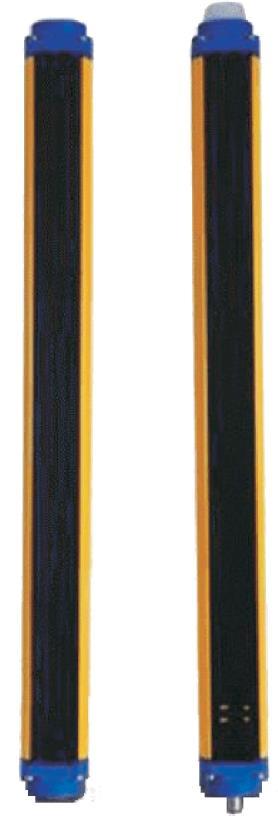
9 2 GENERAL INFORMATIONS ABOUT THE PRODUCT 2.1 GENERAL DESCRIPTION OF THE SAFETY LIGHT CURTAINS The safety light curtains of the SG Body series are optoelectronic multibeam devices that are used to protect working areas that, in presence of machines, robots, and automatic systems in general, can become dangerous for operators that can get in touch, even accidentally, with moving parts. The light curtains of the SG Body series are safety systems used as accident-prevention protection devices and are manufactured in accordance with the international Standards in force for safety, in particular: EN :2013 EN :2013 EN ISO :2008 EN :2010 EN :2010 EN :2010 EN :2010 EN 62061:2005/A1:2013 Safety of machinery: electrosensitive protective equipment. Part 1: General prescriptions and tests. Safety of machinery: electrosensitive protective equipment - Particular requirements for equipment using active optoelectronic protective devices. Safety of machinery. Safety-related parts of control systems. Part 1: General principles for design Functional safety of electrical/electronic/programmable electronic safetyrelated systems. Part 1: General requirements Functional safety of electrical/electronic/programmable electronic safetyrelated systems. Part 2: Requirements for electrical/electronic/programmable electronic safetyrelated systems Functional safety of electrical/electronic/programmable electronic safetyrelated systems. Part 3: Software requirements Functional safety of electrical/electronic/programmable electronic safetyrelated systems. Part 4: Definitions and abbreviations Safety of machinery. Functional safety of electrical/ electronic/programmable electronic safetyrelated control systems. The device, consisting in one active unit inside a sturdy aluminium profile and a passive unit composed of two or more deviating mirrors, generates couples of infrared beams able to detect an opaque object positioned within the light curtain detection field. The active unit is composed of two types of optic groups: emitting and receiving units. The infrared beam, generated by an emitting optic group, is reflected by the deviating mirrors and thus reguided towards the corresponding receiving optic group of the active unit. The passive unit is composed of a sturdy aluminium profile containing pre-assembled and pre-aligned mirrors. The active unit is equipped with the command and control functions. The connections are made through a M12 connector located in the lower side of the profile of the active unit. The microprocessor guarantees the check and the management of the beams that are sent and received through the units: The microprocessor LEDs and display inform the operator about the general conditions of the safety light curtain (see section 8 - DIAGNOSTICS ). The device consists in 2 units: the active unit and the passive unit. The active unit, according to the model, is composed by one or several emitting and receiving modules and checks the control operations and safety actions. During installation, a user interface facilitates the alignment of both units (see section 7 ALIGNMENT PROCEDURE ) 2
10 SG BODY REFLECTOR BASE As soon as an object or the operator s body accidentally interrupts one or some of the infrared beams sent by the emitter, the receiver immediately opens the OSSD outputs and blocks the MPCE machine (if correctly connected to the OSSD). Some parts or sections of this manual containing important information for the user or installing operator are preceded by a note: Notes and detailed descriptions about particular characteristics of the safety devices in order to better explain their functioning. Special instructions regarding the installation process. The information provided in the paragraphs following this symbol is very important for safety and may prevent accidents. Always read this information accurately and carefully follow the advice to the letter. This manual contains all the information necessary for the selection and operation of the safety devices. However, specialised knowledge not included in this technical description is required for the planning and implementation of a safety light curtain on a power-driven machine. As the required knowledge may not be completely included in this manual, we suggest the customer to contact DATALOGIC Technical Service for any necessary information relative to the functioning of the SG BODY light curtains and the safety rules that regulate the correct installation (see section 9) 3
11 2.2 APPEARANCE AND INTERFACE Package contents Package contains the following objects: Active unit SG BODY quick installation guide Checklist and periodical maintenance schedule 2.3 MAIN FUNCTIONS AND NEW FEATURES With respect to SE4-R series, the SG BODY safety light curtain series present new important features: No dead zone New engineering of passive unit Shorter response time (see section 11 TECHNICAL DATA ) Muting function customization Override function customization 2.4 HOW TO CHOOSE THE DEVICE There are at least three different main characteristics that should be considered when choosing a safety light curtain, after having evaluated the risk assessment: Resolution The resolution of the device is the minimum dimension that an opaque object must have in order to obscure at least one of the beams that constitute the sensitive area. The resolution strictly depends on the part of the body to be protected. The following table shows the values of the optic interaxis (I), the resolution (R) and the optic diameter (d), of the safety light curtains. Model Optic interaxis (I) [mm] N. optics Resolution (R) [mm] Lens diameter (d) [mm] ESPE Type Body protection SG4-RB2-050-OO-E ,75 19,75 Type 4 Body protection SG4-RB3-080-OO-E ,75 19,75 Type 4 Body protection SG4-RB4-090-OO-E ,75 19,75 Type 4 Body protection SG4-RB4-120-OO-E ,75 19,75 Type 4 4
12 SG BODY REFLECTOR BASE As shown in Figure 1, the resolution depends only on the geometrical characteristics of the lenses, diameter and distance between centres, and is independent from any environmental and operating conditions of the safety light curtain. d R I ACTIVE PASSIVE Figure 1 The resolution value is obtained applying the following formula: R = I + d where: I = d = Distance between two adjacent optics Lens diameter Note: Safety light curtains for body protection with sensitive area heights and optic interaxis different from the standard versions can be manufactured upon specific request. 5
13 2.4.2 Controlled height The controlled height is the height protected by the safety light curtain (Hp). SG BODY models have no dead zone inside the protected area. In Figure 2, Figure 3 and Figure 4 SG BODY Reflector schemes respectively for 2 beams, 3 beams and 4 beams models are shown. CONTROLLED HEIGHT CONTROLLED AREA Hp ACTIVE PASSIVE ACTIVE Reference Figure 2 6
14 SG BODY REFLECTOR BASE CONTROLLED HEIGHT CONTROLLED AREA ACTIVE PASSIVE Figure 3 CONTROLLED HEIGHT CONTROLLED AREA ACTIVE PASSIVE Figure 4 7
![Model Hp [mm] ESPE Type Body protection SG4-RB2-050-OO-E 500 SG4-RB3-080-OO-E 800 Type 4 Body protection SG4-RB4-090-OO-E 900 Type 4 Body protection SG4-RB4-120-OO-E 1200 Type 4 Body protection Type](/docs-images/88/117758419/images/15-0.jpg "4 2.4.3 Minimum installation distance As shown in Figure 5, the safety device must be positioned at a specific safety distance.")
15 Model Hp [mm] ESPE Type Body protection SG4-RB2-050-OO-E 500 SG4-RB3-080-OO-E 800 Type 4 Body protection SG4-RB4-090-OO-E 900 Type 4 Body protection SG4-RB4-120-OO-E 1200 Type 4 Body protection Type Minimum installation distance As shown in Figure 5, the safety device must be positioned at a specific safety distance. This distance must ensure that the dangerous area cannot be reached before the dangerous motion of the machine has been stopped by the ESPE. The safety distance depends on 4 factors, according to the EN ISO Safety of machinery - The positioning of protective equipment in respect of approach speeds of parts of the human body Standard: Response time of the ESPE (the time between the effective beam interruption and the opening of the OSSD contacts). Machine stopping time (the time between the effective opening of the contacts of the ESPE and the real stop of the dangerous motion of the machine). ESPE resolution. Approaching speed of the object to be detected. Figure 5 The following formula is used for the calculation of the safety distance: S = K (t 1 + t 2 ) + C where: S = Minimum safety distance in mm. K = Speed of the object, limb or body approaching the dangerous area in mm/sec. t 1 = Response time of the ESPE in seconds (see section 11 TECHNICAL DATA ) t 2 = Machine stopping time in seconds. d = Resolution of the system. C = Additional distance based on the possibility to insert the body or one of body parts inside the dangerous area before the protective device trips. C = 8 (d -14) for devices with resolution 40mm C = 850 mm for devices with resolution > 40mm 8
 from machine supporting base while the height of the bottom beam has to be 300 mm (H1).")
16 SG BODY REFLECTOR BASE NOTE: K value is: 2000 mm/s if the calculated value of S is 500 mm 1600 mm/s if the calculated value of S is > 500 mm When devices with > 40 mm resolution are used, the height of the top beam has to be 900 mm (H2) from machine supporting base while the height of the bottom beam has to be 300 mm (H1). If the safety light curtain must be mounted in a horizontal position (Figure 6), the distance between the dangerous area and the most distant optical beam must be equal to the value calculated using the following formula: S = 1600 mm/s (t 1 + t 2 ) H where: S = Minimum safety distance in mm. t 1 = Response time of the ESPE in seconds (see section 11 TECHNICAL DATA ) t 2 = Machine stopping time in seconds. H = Beam height from ground. This height must always be less than 1000 mm. Figure 6 Practical examples Let's suppose to have a light curtain with height = 500 mm To calculate the distance of the device from the ESPE, in a vertical position, the following formula is used: S = K*T + C where: T = t 1 + t 2 t 1 = ESPE response time + SE-SR2 relay release time (max 80 ms) t 2 = Machine total stopping time (e.g. 300 ms). C = 8 (d -14) for devices with resolution 40mm C = 850 mm for devices with resolution > 40mm d = resolution In all cases, if K = 2000mm/sec then S > 500 mm. Distance will have then to be recalculated using K = 1600 mm/sec. SGx-RB2 SGx-RB4 T [sec] C [mm] S [mm] x = ESPE Type: 2,4 WARNING: The reference standard is EN ISO Machine safety - the positioning of the protective device based on the approaching speed of the human body. The following information is to be considered as indicative and concise. For correct safety distance please refer to complete standard EN ISO


17 2.5 TYPICAL APPLICATIONS The safety light curtains of the SG BODY Series are used in all fields where control and protection of the access to dangerous zones is necessary, as well as allowing, by means of the Muting function, material passage inside a dangerous zone during working. In particular they are used to stop the moving mechanical parts in: - Access control - Working areas - Packaging machines, handling machines, storing machines; - Automatic and semi automatic assembly lines; - Automatic warehouses; - Robotics. In food industry applications, Datalogic Technical Service has to verify the compatibility of the material of the safety light curtain housing with any chemical agents used in the production process. The following pictures show some main applications. Figure 7 - Robotised assembly lines Figure 8 - Transfer areas 10
18 SG BODY REFLECTOR BASE 2.6 SAFETY INFORMATION For a correct and safe use of the safety light curtains of the SG BODY series, the following points must be observed: The stopping system of the machine must be electrically controlled. This control system must be able to stop the dangerous movement of the machine within the total machine stopping time T as per paragraph 2.4.3, and during all working cycle phases. Mounting and connection of the safety light curtain must be carried out by qualified personnel only, according to the indications included in the special sections (refer to sections 3, 4, 0, 7) and to the applicable standards. The safety light curtain must be securely placed in a particular position so that access to the dangerous zone is not possible without the interruption of the beams (refer section 3 INSTALLATION MODE ). The personnel operating in the dangerous area must be well trained and must have adequate knowledge of all the operating procedures of the safety light curtain. The TEST button must be located outside the protected area because the operator must check the protected area during all the Test operation. The RESET/RESTART button must be located outside the protected area because the operator must check the protected area during all the Reset/Restart operations. The function of the external device monitoring (EDM) is active only if the specific wire is correctly connected to the device. Please carefully read the instructions for the correct functioning before powering the light curtain. Please carefully read the instructions for the correct functioning before powering the light curtain. 11
19 3 INSTALLATION MODE 3.1 PRECAUTIONS TO BE OBSERVED FOR THE CHOICE AND INSTALLATION OF THE DEVICE Make sure that the protection level assured by the SG BODY series device (Type 2 or Type 4 respectively) is compatible with the real danger level of the machine to be controlled, according to EN and EN The outputs (OSSD) of the ESPE must be used as machine stopping devices and not as command devices (the machine must have its own START command). The dimension of the smallest object to be detected must be larger than the resolution level of the device. The ESPE must be installed in a room complying with the technical characteristics indicated in section 11 - TECHNICAL DATA. Datalogic does not recommend the use of the product in ambient where direct or indirect exposure to solar light is present. Do not install device near strong and/or flashing light sources or close to similar devices. Strong electromagnetic disturbance might negatively affect device operation. Should this be the case contact DATALOGIC Technical Service. The operating distance of the device can be reduced in presence of smog, fog or airborne dust. A sudden change in environment temperature, with very low minimum peaks, can generate a small condensation layer on the lenses and so jeopardise functioning. 12


20 SG BODY REFLECTOR BASE 3.2 GENERAL INFORMATION ON DEVICE POSITIONING Pay special care when positioning the safety light curtain so to offer effective protection. The device should be installed in such a way that the dangerous area can only be entered after detecting the sensitive area. Figure 9 shows some examples of possible access to the machine from the top and the bottom sides. These situations may be very dangerous and so the installation of the safety light curtain at sufficient height in order to completely cover the access to the dangerous area becomes necessary (see Figure 10). NO Figure 9 YES Figure 10 Under standard operating conditions, machine starting must not be possible while operators are inside the dangerous area. When the installation of the safety light curtain very near to the dangerous area is not possible, a second light curtain must be mounted in a horizontal position in order to prevent any lateral access, as shown in Figure 12. If the operator is able to enter the dangerous area, an additional mechanical protection must be mounted to prevent the access. NO SI Figure 11 Figure 12 13
21 3.2.1 Minimum installation distance Refer to paragraph Minimum installation distance Minimum distance from reflecting surfaces Reflecting surfaces placed near the light beams of the safety device (over, under or laterally) can cause passive reflections. These reflections can affect the recognition of an object inside the controlled area. However, if the RX receiver detects a secondary beam (reflected by the side-reflecting surface) the object might not be detected, even if the object interrupts the main beam. ACTIVE UNIT PASSIVE UNIT ACTIVE UNIT PASSIVE UNIT Figure 13 It is thus important to position the safety light curtain according to the minimum distance from reflecting surfaces. The minimum distance depends on: operating distance between active and passive units. real aperture angle of ESPE (EAA); especially: for ESPE type 4 EAA MAX = 5 (α = ± 2.5 ) 14
22 SG BODY REFLECTOR BASE Diagram of Figure 14 shows the minimum distance from the reflecting surface (D sr ), based on the operating distance for a Type 4 ESPE: Minimum distance from reflecting surfaces (DSR) m Operating distance (D op ) ESPE Type 4 8 m Figure 14 The formula to get D sr for a Type 4 ESPE is the following: D sr (m) = 0.15 D sr (m) = 0.5 x operating distance (m) x tg 2 for operating distance < 3 m for operating distance 3 m Even in presence of beam interruption due to reflecting objects, the correct device functioning is guaranteed and certified up to a maximum operating distance of 6.5m for SG4-RB4-090 model, or 8 m for SG4-RB2-050, SG4-RB3-080, SG4-RB4-120 models. The use of the device at higher distances, when possible, is however not recommended. If used, the user must check the correct functioning verifying that no dangerous reflections towards the receiving optics are generated by shiny objects (Figure 15). TX reflecting object RX Figure 15 15
23 3.2.3 Distance between homologous devices If different safety devices have to be installed in adjacent areas, the emitter of one device must not interfere dangerously with the receiver of the other device. Passive B interfering device must be positioned outside a minimum D do distance from the active passive axis of the device A. PASSIVE A ACTIVE A PASSIVE B ACTIVE B Figure 16 This minimum D do distance depends on: the operating distance between Passive A and Active A; the effective aperture angle of the ESPE (EAA); especially: for ESPE type 4 EAA MAX = 5 (α = ± 2.5 ) WARNING: the interfering device Passive B must be positioned at the same D do distance, calculated as shown above, even if closer to Passive A respect to Active A. The following graphic shows the distance from the interfering devices (D do ) according to the operating distance (D op ) of the couple Passive A Active A for a Type 4 ESPE. m Homolugous devices distance (Ddo) ESPE Type Operating distance (D op ) 8 m Figure 17 The formula to get D op for a Type 4 ESPE is the following: D op (m) = 0.3 D op (m) = operating distance (m) x tg 2 for operating distance < 3 m for operating distance 3 m Installation precautions have to be taken to avoid interference between homologous devices. A typical situation is represented by the installation areas of several adjacent safety devices aligned one next to the other, for example in plants with different machines. 16
24 SG BODY REFLECTOR BASE Figure 18 provides some examples for a 4 beam device; obviously a contemporary activation of more emitters is not possible and the emitter/receiver couples are activated sequentially. RX RX TX TX NO TX TX RX RX NOT RECOMMENDED RX TX TX RX RX TX TX RX NOT RECOMMENDED RX TX TX RX RX TX TX RX RX RX YES TX TX RX OPAQUE SURFACE TX TX RX Figure 18 17


25 3.2.4 Active and passive orientation The two units shall be assembled parallel each other, and looking at the references on the aluminium profile. The configurations shown in must be avoided. Figure Precautions to respect during the use of deviating mirrors The operator must observe the following precautions when using the deviating mirrors: The alignment of the active unit can become a very critical operation when deviating mirrors are used. Even a very small angular displacement of the mirror is enough to loose alignment. The SG-LP laser pointer accessory can be used to avoid this problem. The presence of dust or dirt on the reflecting surface of the mirror causes a drastic reduction in the range Controls after first installation The control operations to carry-out after the first installation and before machine start-up are listed hereinafter. The controls must be carried-out by qualified personnel, either directly or under the strict supervision of the person in charge of machinery Safety. Verify that: ESPE remains in SAFE state ( ) intercepting the beams along the protected area using the specific test piece (TP-40, TP-50, TP-90), following the Figure 20 scheme. Figure 20 18
26 SG BODY REFLECTOR BASE ESPE has to be correctly aligned, press slightly on the product side in both directions the red LED must not turn on. The activation of the TEST function causes the opening of the OSSD outputs (red LED on and controlled machine stop). The response time at machine STOP, including the ESPE and machine response times, must be included in the limits defined in the calculation of the safety distance (refer to section 3 INSTALLATION MODE ). The safety distance between the dangerous parts and ESPE must comply with the requirements indicated in section 3 INSTALLATION MODE. A person must not access or remain between ESPE and the dangerous parts of the machine. Access to the dangerous areas of the machine must not be possible from any unprotected area. ESPE must not be disturbed by external light sources, ensuring that it remains in NORMAL OPERATION condition for at least minutes and, placing the specific test piece in the protected area, in the SAFE state for the same period. Verify the correspondence of all the accessory functions, activating them in the different operating conditions. 19
. The two units must be positioned the most aligned and parallel possible. The next step is the fine alignment, as shown in section 7 ALIGNMENT PROCEDURE.")

27 4 MECHANICAL MOUNTING The active and passive units must be installed with the relevant sensitive surfaces facing each other and the distance must be included within the operating range of the model used (see section 13). The two units must be positioned the most aligned and parallel possible. The next step is the fine alignment, as shown in section 7 ALIGNMENT PROCEDURE. SG BODY series light curtains are provided without mounting brackets. It is possible to order separately the accessory kits of brackets described in the following paragraphs depending on the fastening mode required by the particular application. Please refer to section 14 ACCESSORIES. 4.1 SIDE FIXING BRACKETS As all the Datalogic SG series safety light curtains, the most common way to fix the product is by taking advantage from the two grooves along the sides of the aluminium case, the 90 bracket system is made by ST IM-5018 and screws (see Figure 21). Figure 21 The ST-5090 is a 4 mm thickness sheet metal. The IM-5018 is a double nut M5 tapped obtained by machine tooling (for further details and recommended mounting positions see also paragraph 14.1). 4.2 ROTATING BRACKETS The rotate fixing has been improved and revised due to the size of the caps. Is possible indeed to ensure a 360 rotation around the dedicated cylindrical surfaces designed on the caps themselves. To obtain this is necessary to use the ST-5089, 4 mm thickness sheet metal with a special, dedicated shape. The screw to fix this bracket is the same one used to fix the closing caps, with an M4 nut (see Figure 22). For further information refer to paragraph Figure 22 20


28 SG BODY REFLECTOR BASE 4.3 BOTTOM FIXING BRACKETS With the SG BODY series has been implemented a new kind of bracket fixing, by using the third groove, on the bottom side of the housing, that allows to use whether the 90 bracket ST-5090 or the new ST-5093 and, in both the cases, the same IM-5018 and screws seen before. This kind of fixing is also very versatile in order to assembly the product into the new Protective Stands mechanical armour. Figure 23 The ST-5093 is a 4 mm thickness sheet metal as well. For further details and recommended mounting positions see also paragraph VIBRATION DAMPERS In case of applications with particularly strong vibrations, vibration dampers together with mounting brackets are recommended to reduce the impact of the vibrations (see Figure 24). Figure 24 21
29 5 ELECTRICAL CONNECTIONS AND CONFIGURATION STOP All electrical connections to the emitting and receiving units are made through male M12 connectors, located on the lower part of the two units. For active unit a M12 8-poles connector is used. 5.1 IMPORTANT NOTES FOR INSTALLATION For the correct functioning of the SG BODY series safety light curtains, the following precautions regarding the electrical connections have to be respected: Do not place connection cables in contact with or near high-voltage cables and/or cable undergoing high current variations (e.g. motor power supplies, inverters, etc.); Do not connect in the same multi-pole cable the OSSD wires of different light curtains; The device is already equipped with internal overvoltage and overcurrent suppression devices. The use of other external components is not recommended. 22
30 SG BODY REFLECTOR BASE 5.2 MINIMAL CONNECTION Wires configuration: EDM disabled, automatic restart Power supply: 0V, 24V (0-24 Vdc) +24Vdc 0V NC RESET/RESTART/RESTART MODE line +24Vdc 0V or floating EDM ENABLE line OTHER lines: floating 5.3 COMPLETE CONNECTION LIST RX M12 8 poles: 1 = white = RESET/RESTART/RESTART MODE 2 = brown = 24V 3 = green = EDM ENABLE 4 = yellow = EDM 5 = grey = OSSD1 6 = pink = OSSD2 7 = blue = 0V 8 = red = EARTH 5.4 RESTART MODE AND RESET/RESTART BUTTON CONNECTION The Restart mode and Reset/Restart wire must be connected through a N.C. button to the 0V or 24V from the power supply of the ESPE to select, respectively, manual restart or automatic restart. The Reset/Restart wire can be used to enter alignment function, when N.C. button is pressed at startup. The RESET/RESTART button must be located in such a way that the operator can check the protected area during any reset operation. 23
31 5.5 EXTERNAL RELAYS CONNECTION Example: connection to the safety relay. Figure 25 The previous figure shows the connection between the safety light curtains and the safety relay of the SE-SR2 series functioning in the Automatic Restart mode (left side) and Manual Restart with monitoring (right side). Do not use varistors, RC circuits or LEDs in parallel at relay inputs or in series at OSSD outputs. The OSSD1 and OSSD2 safety contacts cannot be connected in series or in parallel, but must be used separately (Figure 26), conforming to the plant s safety requirements. If one of these configurations is erroneously used, the device enters into the output failure condition (see section 8 DIAGNOSTIC ). Connect both OSSDs to the activating device. Failure to connect an OSSD to the activating device jeopardises the system safety degree that the light curtain has to control. 24
32 SG BODY REFLECTOR BASE YES Figure 26 NO Figure 27 24Vdc OSSD1 GND 24Vdc OSSD2 GND 115 usec 500 msec 1000 msec OSSD test behaviour in NORMAL OPERATION state Figure 28 25
33 5.6 EDM ENABLE INPUT CONNECTION The EDM ENABLE wire must be connected to 0V or 24V from the power supply of the ESPE, respectively, to enable or to disable EDM function. Floating line level is the same as 0V. 5.7 EDM CONTROL CONNECTION The EDM wire has to be connected to a 24 Vdc normally closed contact, before powering. The monitoring function, if selected, is not activated if at powering the wire is not correctly connected; in this case the light curtain enters in a failure condition. 5.8 EARTH CONNECTION The SG BODY safety light curtain has to be connected as a protective class III equipment (SELV/PELV power supply), like in the table. Electrical protection layout connection note class III SELV/PELV --- A functional earth is available on a line of the M12 connector on TX and RX equipment. User can optionally connect or leave floating the functional earth in order to achieve in own application a best compliance with electromagnetic Interferences. 26
34 SG BODY REFLECTOR BASE 6 FUNCTIONING MODE 6.1 STANDARD CONFIGURATION LINE LAYOUT CONNECTION BEHAVIOUR RESET/RESTART/ RESTART MODE +24Vdc NC RESET/RESTART/ RESTART MODE AUTOMATIC RESTART RESET/RESTART/ RESTART MODE 0V NC RESET/RESTART/ RESTART MODE MANUAL RESTART 24Vdc OSSD_1 nc no EDM OSSD_2 (EDM ENABLE: active) nc no EDM to ESPE forced guide relais EDM ENABLE 0V or floating EDM ENABLE EDM enabled OSSDs OSSDs 0V 27
35 6.2 RESET FUNCTION The RX light curtain has a RESET function that is activated consequently to an internal failure. The operator has to press the NC RESET button that resetting the break condition and thus the ESPE can return to a normal functioning behaviour. The button has to be kept pressed for at least 5 seconds in one of the following conditions: Output failure; Optic failure; EDM test function failure; Safety light curtain STATUS Failure Normal Contact open RESET Contact close 5 sec If the error is not removed, the light curtain goes in the failure configuration (for all failures) yet. Notes: the micro controller failure is a non-restorable failure. In this case is necessary a turn OFFturn ON action to return to a normal behavior. This is also valid for the following failures: Restart selection failure Override connection failure Override sequence failure Dip switch failure 28
36 SG BODY REFLECTOR BASE 6.3 RESTART MODE SELECTION FUNCTION The interruption of a beam due to an opaque object causes the opening of OSSD outputs and the stop of the safety light curtain, SAFE condition. ESPE standard operation can be reset to NORMAL OPERATION condition (OSSD safety contact closing condition, ) in two different ways: Automatic Restart: after activation, ESPE resets to NORMAL OPERATION condition once the object has been removed from the controlled area. Manual Restart: after activation, ESPE resets to NORMAL OPERATION condition only once the Restart function has been enabled and provided that the object has been removed from the controlled area (see Figure 29). This condition, called interlock, is signalled on the display (see paragraph 8.2 Diagnostic messages ). WARNING: Carefully assess risk conditions and restart modes. In applications protecting access to dangerous areas, the automatic restart mode is potentially unsafe if it allows the operator to pass completely beyond the sensitive area. In this case, the manual restart or, for example, the manual restart of the SE-SR2 relay (paragraph 5.5 External relays connection ) is necessary. OSSDs STATUS NORMAL OPERATION SAFE INTERLOCK STATUS ON OFF RESTART Contact open Contact close 0.5 sec Figure 29 Time chart for manual restart Select either automatic or manual restart by connecting pin of RX connector. (see section 5 ELECTRICAL CONNECTIONS AND CONFIGURATION ) 29
37 6.4 EDM FUNCTION The light curtain has a function for monitoring actuation external devices (EDM). This function can be enabled or deactivated by pin of RX connector (. (see section 5 ELECTRICAL CONNECTIONS AND CONFIGURATION ) EDM deactivated: Disconnect or connect to 0V EDM input pin of RX connector. EDM enabled: Connect EDM input pin of RX connector. (see section 5 ELECTRICAL CONNECTIONS AND CONFIGURATION ) to a 24 VDC normally closed contacts of the device to be monitored (see Figure 30). NOTE: The decimal dot on the display shows that the function is enabled. 24Vdc OSSD_1 nc no OSSD_2 nc no EDM to ESPE forced guide relais Figure 30 The function controls the NC contact switching according to the changes of the OSSD status. The timing diagram below explains the relationship between the cause (OSSDs) and the effect (EDM), with the maximum permissible delay. OSSDs STATUS NORMAL OPERATION SAFE EDM 24Vdc 0Vdc Tc To Figure 31 Tc T0 350 msec time after the OSSD OFF-ON passage when EDM is carried-out; 100 msec time after the OSSD ON-OFF passage when EDM is carried-out. (two different times for the mechanical contact driven by a spring). 30
38 SG BODY REFLECTOR BASE 6.5 ALIGNMENT FUNCTION SG BODY series light curtains are fitted with a system which informs the user about reached alignment degree. The ALIGNMENT function also can be activated by simply pressing the external normally closed push-button link to RESET/RESTART/RESTART MODE line (see section 5 ELECTRICAL CONNECTIONS AND CONFIGURATION ) for at least 0.5 sec at start-up, as shown in the timing diagram of Figure 32. STATE OF LIGHT CURTAIN (POWER) ON OFF RESET/RESTART/RESTART MODE 24Vdc 0Vdc STATE OF ALIGNMENT FUNCTION ON 0.5 s OFF Figure 32 When a good state of alignment is reached a power OFF and a power ON operation carry back the ESPE in normal operation (OSSDs in ON state). In the alignment mode the OSSDs are OFF. 31
39 7 ALIGNMENT PROCEDURE The good alignment between the active and the passive unit of the ESPE is necessary to obtain the correct behaviour of the light curtain. A good alignment avoid a not steady light curtain status (OSSDs flicker on off and vice versa) due to dust or vibration. The alignment is perfect if the optic axes of the active unit s beams coincide with the optic axes of the corresponding mirrors on the passive unit. It is important to define the means of symbol drawn on optic side of light curtain. The direction of arrows associated to the two yellow led are correlated to the first and the last emitter/receiver couple, referring the position of M12 connector. Signals are clearly identified through symbols allowing their immediate reading, independent of bars directions; a short description of LEDs signals proves nevertheless necessary so as to avoid misunderstandings. NORMAL OPERATION SAFE LAST FIRST Figure 33 Figure 34 shows that the first couple emitter/receiver is the nearest to M12 connector; the last couple emitter/receiver is the farest to M12 connector. The standard installation described hereinafter is the one shown in Figure 34 for a SG4-RB4 model, i.e. with the bar assembled with the connectors pointing down. In SG4-RB2 models, obviously, the first and the last couple coincide. Last emitter/receiver couple First emitter/receiver couple ACTIVE PASSIVE Figure 34 32
. Figure 35 7.")
40 SG BODY REFLECTOR BASE An one digit display can inform the user about the level of alignment of the array of beams. As operating distance increase, the SG-LP laser pointer tool attached on active or passive unit can be used to help the user to obtain the best alignment (see Figure 35). Figure LIGHT CURTAIN ALIGNMENT PROCEDURE The light curtain alignment can be effected only after having completed the mechanical installation and the electrical connections as described above. Compare alignment results with those given in the following table. To enter alignment mode see paragraph 6.5 Alignment function. ATTENTION: in alignment mode the OSSDs of the light curtain are in OFF state VISUALIZATION ALIGNMENT STATE ALIGNMENT QUALITY OSSD STATE OUT OF ALIGNMENT- FUNCTION first and last couple are not aligned bad OFF last couple isn t aligned bad OFF first couple isn t aligned bad OFF every couple over the lower threshold and no couple over the upper threshold every couple over the lower threshold and one couple over the upper threshold every couple over the upper threshold good excellent ON ON ON 1. Keep the active unit in a steady position and set the passive unit until the yellow LED ( FIRST) is OFF. This condition shows the alignment of the first emitter/receiver couple. 2. Rotate the passive unit, pivoting on the lower optics axis, until the yellow LED ( LAST) is OFF. NOTE: Ensure that the green LED ( NORMAL OPERATION) is steady ON. 33
41 3. Delimit the area in which the green LED ( ) is steady through some micro adjustments - for the first and then for the second unit - so to have the maximum alignment (3) and then place both units in the centre of this area. 4. Fix the two units firmly using brackets. Verify that the green LED ( ) on the active unit is ON and beams are not interrupted, then verify that the red LED SAFE ( ) turns ON if even one single beam is interrupted (condition where an object has been detected). This verification shall be made with the special cylindrical Test Piece having a size suitable to the resolution of the device used (refer paragraph Controls after first installation ). 5. Switch OFF and ON the device in normal operating mode. The alignment level is monitored also during device normal operating mode, and is visualized by a bar graph shown on the user interface. Once the curtain has been aligned and correctly fastened, the display signal is useful to check the alignment and to view any change in the environmental conditions (presence of dust, light disturbance and so on). The behavior is resumed in the next table. VISUALIZATION ALIGNMENT STATE every couple over the lower threshold and no couple over the upper threshold every couple over the lower threshold and one couple over the upper threshold every couple over the upper threshold ALIGNMENT QUALITY min excellent 34
42 SG BODY REFLECTOR BASE 8 DIAGNOSTICS 8.1 USER INTERFACE A user interface aids the customer to control and check the state of the light curtain, for alignment mode, normal operation and for troubleshooting activity. User interface is composed by four LEDs and an one-digit display on the active unit. NORMAL OPERATION SAFE LAST FIRST Figure DIAGNOSTIC MESSAGES Active unit side The table completely explains all the visualization informations exept those relative to the alignment function (see par. 7.1 Light curtain alignment procedure ). VISUALIZATION STATUS DESCRIPTION ACTION INTERLOCK INTERLOCK FREE BEAMS, OSSDS OFF INTERRUPTED BEAMS, OSSDS OFF USER CAN TAKE DEVICE IN NORMAL OPERATION ACTIVATING RESTART LINE. USER MUST FREE BEAMS PATH BEFORE ACTIVATING RESTART LINE. NORMAL OPERATION OSSDS ON SAFE OSSDS OFF NORMAL OPERATION, SAFE, INTERLOCK NORMAL OPERATION, SAFE, INTERLOCK EDM FUNCTION ACTIVE EDM FUNCTION NOT ACTIVE FAILURE LOCKOUT (RECOVERABLE) FAILURE ON ONE OR BOTH OSSDS, OSSDS OFF USER MUST ACTIVATE RESET LINE. IF ESPE DOES NOT RESET USER MUST CONTACT DATALOGIC TECHNICAL SUPPORT. 35
43 VISUALIZATION STATUS DESCRIPTION ACTION FAILURE LOCKOUT (NOT RECOVERABLE) MICROCONTROLLER FAILURE, OSSDS OFF USER MUST TURN OFF/ON ESPE. IF THE PROBLEM PERSISTS USER MUST CONTACT DATALOGIC TECHNICAL SUPPORT. FAILURE LOCKOUT (RECOVERABLE) OPTICAL FAILURE, OSSDS OFF USER MUST ACTIVATE RESET LINE. IF ESPE DOES NOT RESET USER MUST CONTACT DATALOGIC TECHNICAL SUPPORT. FAILURE LOCKOUT (RECOVERABLE) ESPE OFF EDM FAILURE, OSSDS OFF POWER SUPPLY FAILURE, OSSDS OFF USER MUST CHECK EDM ENABLE LINE OR DIP- SWITCHES, EDM LINE, EXTERNAL SWITCHING DEVICE AND ACTIVATE RESET LINE. IF ESPE DOES NOT RESET USER MUST CONTACT DATALOGIC TECHNICAL SUPPORT. USER MUST CHECK POWER SUPPLY CONNECTION. IF THE PROBLEM PERSISTS USER MUST CONTACT DATALOGIC TECHNICAL SUPPORT. 36
44 SG BODY REFLECTOR BASE 9 PERIODICAL MAINTENANCE AND WARRANTY The following is a list of recommended check and maintenance operations that should be periodically carried-out by qualified personnel (see also paragraph Controls after first installation ) Check that: The ESPE stays in SAFE state ( ) during beam interruption along the entire protected area, using the specific Test Piece (TP-40, TP-50, TP-90), according to the Figure 20 scheme. The ESPE is correctly aligned. Press slightly product side, in both directions and the red LED ( ) must not turn ON. Enabling the TEST function, the OSSD outputs should open (the red LED is ON and the controlled machine stops). The response time upon machine STOP (including response time of the ESPE and of the machine) is within the limits defined for the calculation of the safety distance (see section 3 INSTALLATION MODE ). The safety distance between the dangerous areas and the ESPE are in accordance with the instructions included in section 3 INSTALLATION MODE. Access of a person between ESPE and machine dangerous parts is not possible nor is it possible for him/her to stay there. Access to the dangerous area of the machine from any unprotected area is not possible. The ESPE and the external electrical connections are not damaged. The frequency of checks depends on the particular application and on the operating conditions of the safety light curtain. 37
45 9.1 GENERAL INFORMATION AND USEFUL DATA Safety MUST be a part of our conscience. The safety devices fulfil their safety function only if they are correctly installed, in accordance with the Standards in force. If you are not certain to have the expertise necessary to install the device in the correct way, Datalogic Technical Support is at your disposal to carry out the installation. The device uses fuses that are not self-resetting. Consequently, in presence of short-circuits causing the cut-off of these fuses, both units shall be sent to Datalogic Technical Support department. A power failure caused by interferences may cause the temporary opening of the outputs, but the safe functioning of the light curtain will not be compromised. 9.2 WARRANTY Datalogic guarantees each brand new SG BODY system, under standard use conditions, against manufacturing defects in material and workmanship for a period of 36 (thirty-six) months from the date of manufacturing. Datalogic will not be liable for any damages to persons and things caused by wrong installation modes or device use. Warranty validity is subject to the following conditions: User shall notify Datalogic the failure within thirty-six months from product manufacturing date. Failure or malfunction shall not have been originated directly or indirectly by: use for unsuitable purposes; failure to comply with the intended use prescriptions; negligence, unskillfulness, wrong maintenance; repairing, changes, adaptations not made by Datalogic personnel, tampering with the device, etc.; accidents or crashes (even due to transportation or by force majeure causes); other causes not depending from Datalogic If the device does not work, send both units (receiver and emitter) to Datalogic. The Customer is responsible for all transport charges and damage risks or material loss during transport, unless otherwise agreed. All replaced products and parts become a property of Datalogic. Datalogic does not accept any warranty or right other than the above-described ones. No requests for compensation for expenses, activities stop or other factors or circumstances somehow connected to the failure of the product or one of its parts to operate cannot be put forward for any reason. In case of problems, please contact DATALOGIC Service Department. Technical Support Tel.: Fax.:
46 SG BODY REFLECTOR BASE 10 DEVICE MAINTENANCE SG Body safety light curtains do not require special maintenance operations. To avoid the reduction of the operating distance, optic protective front surfaces must be cleaned at regular intervals. Use soft cotton cloths damped in water. Do not apply too much pressure on the surface in order to avoid making it opaque. Please do not use on plastic surfaces or on light curtain painted surfaces: alcohol or solvents wool or synthetic cloths paper or other abrasive materials 10.1 PRODUCT DISPOSAL Under current Italian and European laws, Datalogic is not obliged to take care of product disposal at the end of its life. Datalogic recommends to dispose of the product in compliance with local laws or contact authorised waste collection centres. 39
47 11 TECHNICAL DATA Electrical Data Power supply 24 Vdc 20% Active unit consumption (RX) Outputs: Output current: Output voltage - ON min: Output voltage - OFF max: Output capacitive load Response time: Protected height: 6.5 W max (without load) 2 PNP outputs short-circuit protection (1.4 C) 0.5 A max / each output Power supply value less 1 V 0.2 V 2.2 From 11 to 24 ms See section 13 LIST OF AVAILABLE MODELS from 500 mm to1200 mm See section 13 LIST OF AVAILABLE MODELS Safety category: Type 4 (ref. EN ) SIL 3 (ref. EN 61508) SIL CL 3 (ref. EN 62061) PL e Cat. 4 (ref. IEC ) See section 13 LIST OF AVAILABLE MODELS Auxiliary functions: Electrical protection: Connections: Cable length ( for power supply): Reset, Restart selection, Alignment, EDM class III M12 8 poles 70 m. max Pollution degree 2 Optical Data Light source: Infrared LED (950 nm wavelength ) Resolution: Beam spacing Operating distance: 40 mm 319,75 mm 419,75 mm 519,75 mm 20 mm 300 mm 400 mm 500 mm Ambient light rejection: IEC Operating temperature: From 0,5 to 8 mt See section 13 LIST OF AVAILABLE MODELS Mechanical and environmental data 0 55 C Storage temperature: C Temperature class: Humidity: T % (no condensation) Water protection grade: IP 65 (EN 60529) Vibrations: Shock resistance: 0.35 mm width, Hz frequency, 20 sweep for each axis, 1 octave/min (EN ) 16 ms (10g) shock for each axis (EN ) Housing material: Painted aluminium (yellow RAL 1003) Caps material: Front glass material: Connections: Weight: PBT Valox 508 (pantone 072-CVC) PMMA M12 connector SG4-RB2-050-OO-E: 1,3 Kg SG4-RB3-080-OO-E: 1,8 Kg SG4-RB4-090-OO-E: 2,1 Kg SG4-RB4-120-OO-E: 2,6 Kg SG4-RDB2 (passive): 1,2 Kg SG4-RDB3 (passive): 1,7 Kg SG4-RDB4-090 (passive): 1,9 Kg SG4-RDB4-120 (passive): 2,5 Kg (single bar---not packaged) 40
48 SG BODY REFLECTOR BASE 12 OVERALL DIMENSIONS Figure 37 Figure 38 Model L1 [mm] L2 [mm] SG4-RB2-050-OO-E (Figure 37) 606,35 520,5 SG4-RB3-080-OO-E (Figure 37) 906,35 820,5 SG4-RB4-090-OO-E (Figure 37) 1006,35 920,5 SG4-RB4-120-OO-E (Figure 37) 1306, ,5 SG4-RDB2 (Figure 38) 580,5 520,5 SG4-RDB3 (Figure 38) 880,5 820,5 SG4-RDB4-090 (Figure 38) 980,5 920,5 SG4-RDB4-120 (Figure 38) 1280,5 1220,5 41
49 EN ISO EN EN IEC EN IEC Prob. of danger failure/hour Life span Mean Time to Dangerous Failure Average Diagnostic Coverage Safe Failure Fraction Hardware Fault Tolerance 13 LIST OF AVAILABLE MODELS Description Protecte d height (mm) Beams (Nr.) Resolution (mm) Response time (msec) Interaxis (mm) Operating Distance (m) Code SG4-RB2-050-OO-E , SG4-RB3-080-OO-E , SG4-RB4-090-OO-E , SG4-RB4-120-OO-E , SG4-RDB2 (passive) SG4-RDB3(passive) SG4-RDB4-090 (passive) SG4-RDB4-120 (passive) Description PL CAT SIL SIL CL PFHd (1/h) T1 (years) MTTFd (years) DC SFF HFT SG4-RB2-050-OO-E e ,28E ,00% 97,20% 1 SG4-RB3-080-OO-E e ,28E ,00% 97,20% 1 SG4-RB4-090-OO-E e ,28E ,00% 97,20% 1 SG4-RB4-120-OO-E e ,28E ,00% 97,20% 1 42
50 SG BODY REFLECTOR BASE 14 ACCESSORIES (dimensions in mm) 14.1 METAL ANGLED FIXING BRACKET (ST-K4STD-SG BODY BIG) MODEL DESCRIPTION CODE ST-K4STD-SG BODY BIG Angled fixing bracket (4 pcs kit) 95ASE1950 Figure 39 43
51 Modalità di montaggio staffe laterali MODEL DESCRIPTION CODE ST-K4AV Antivibration support (4 pcs kit) 95ACC1700 ST-K6AV Antivibration support (6 pcs kit) 95ACC1710 MOUNTING A MOUNTING B Angled fixing bracket Angled fixing bracket + antivibration support The recommended mounting positions according to the light curtain length are shown and in the subsequent table. MODEL L 2 [mm] A [mm] B [mm] C [mm] CODE SG4-RB2-050-OO-E 520,5 320, SG4-RB3-080-OO-E 820,5 370, SG4-RB4-090-OO-E 920,5 620, SG4-RB4-120-OO-E 1220,5 1020, , SG4-RDB2 (passive) 520,5 320, SG4-RDB3 (passive) 820,5 370, SG4-RDB4-090 (passive) 920,5 620, SG4-RDB4-120 (passive) 1220,5 1020, ,
52 SG BODY REFLECTOR BASE 14.2 ROTATIVE FIXING BRACKET (ST-K4ROT-SG BODY BIG) MODEL DESCRIPTION CODE ST-K4ROT-SG BODY BIG Metal rotative fixing bracket (4 pcs kit) 95ASE1960 Rotative fixing bracket mounting 45
53 14.3 REAR FIXING BRACKET (ST-K4REAR-SG BODY BIG) MODEL DESCRIPTION CODE ST-K4REAR-SG BODY BIG Metal rear fixing bracket (4 pcs kit) 95ASE1970 Rear fixing bracket mounting 46
 MODEL DESCRIPTION CODE SG-PSM-2-500")


54 SG BODY REFLECTOR BASE 14.4 PROTECTIVE STANDS (SG-PSM) MODEL DESCRIPTION CODE SG-PSM Protective stand with 2 mirrors H=500mm 95ASE2300 SG-PSM Protective stand with 3 mirrors H=800mm 95ASE2310 SG-PSM Protective stand with 4 mirrors H=900mm 95ASE2320 SG-PSM Protective stand with 4 mirrors H=1200mm 95ASE2330 SG-PSM SG-PSM SG-PSM SG-PSM
55 14.5 PROTECTIVE STANDS (SG-PSB) MODEL DESCRIPTION L (mm) CODE SG-PSB 600 Protective stand H=600mm ASE2240 SG-PSB 1000 Protective stand H=1000mm ASE2250 SG-PSB 1200 Protective stand H=1200mm ASE2260 SG-PSB 1650 Protective stand H=1650mm ASE2270 SG-PSB 1900 Protective stand H=1900mm ASE2280 Fixing kit MODEL DESCRIPTION CODE ST-PS4-SG-SE Mounting kit (4 pcs kit) 95ASE1750 ST-PS6-SG-SE Mounting kit (6 pcs kit) 95ASE
56 SG BODY REFLECTOR BASE 14.6 PLATE KIT FOR PROTECTIVE STANDS (SG-P) MODEL DESCRIPTION CODE SG-P Plate kit for SG-PSB/SG-PSM 95ASE2290 Mounting with SG-PSB/SG-PSM 49
57 14.7 COLUMNS AND FLOOR STANDS (SE-S) MODEL DESCRIPTION L (mm) X (mm) CODE SE-S 800 Column and floor stand H= 800 mm x30 95ACC1730 SE-S 1000 Column and floor stand H= 1000 mm x30 95ACC1740 SE-S 1200 Column and floor stand H= 1200 mm x30 95ACC1750 SE-S 1500 Column and floor stand H= 1500 mm x45 95ACC1760 SE-S 1800 Column and floor stand H= 1800 mm x45 95ACC
58 SG BODY REFLECTOR BASE 14.8 LASER POINTER (SG-LP) MODEL DESCRIPTION CODE SG-LP Laser pointer 95ASE5590 The laser pointer of the SG-LP series represents a valid alignment and installation support for the safety light curtain series. The pointer can be moved along the light curtain profile to verify the complete device alignment (top and bottom) TEST PIECE (TP) MODEL DESCRIPTION CODE TP-14 Test piece Ø 14mm L = 300mm 95ACC1630 TP-20 Test piece Ø 20mm L=300mm 95ACC1640 TP-24 Test piece Ø 24mm L=300mm 95ASE2570 TP-30 Test piece Ø 30mm L=300mm 95ACC1650 TP-34 Test piece Ø 34mm L=300mm 95ASE2580 TP-35 Test piece Ø 35mm L=300mm 95ACC1660 TP-40 Test piece Ø 40mm L=300mm 95ACC1820 TP-50 Test piece Ø 50mm L=300mm 95ACC1790 TP-90 Test piece Ø 90mm L=300mm 95ACC
59 14.10 CONNECTION CABLES MODEL DESCRIPTION CODE CS-A1-03-U-03 5-pole M12 cable (axial) 3 m 95ASE1170 CS-A1-03-U-05 5-pole M12 cable (axial) 5 m CS-A1-03-U-10 5-pole M12 cable (axial) 10 m CS-A1-03-U-15 5-pole M12 cable (axial) 15 m CS-A1-03-U-25 5-pole M12 cable (axial) 25 m CS-A1-03-U-50 5-pole M12 cable (axial) 50m CS-A1-06-U-03 8-pole M12 cable (axial) 3 m CS-A1-06-U-05 8-pole M12 cable (axial) 5 m CS-A1-06-U-10 8-pole M12 cable (axial) 10 m CS-A1-06-U-15 8-pole M12 cable (axial) 15 m CS-A1-06-U-25 8-pole M12 cable (axial) 25 m CS-A1-06-U-50 8-pole M12 cable (axial) 50 m CS-A1-10-U pole M12 cable (axial) 3 m CS-A1-10-U pole M12 cable (axial) 5 m CS-A1-10-U pole M12 cable (axial) 10 m CS-A1-10-U pole M12 cable (axial) 15 m CS-A1-10-U pole M12 cable (axial) 25 m CS-A1-10-U pole M12 cable (axial) 50 m 95ASE ASE ASE ASE A ASE ASE ASE ASE ASE A A A A A A A
60 SG BODY REFLECTOR BASE SAFETY RELAY MODEL DESCRIPTION CODE SE-SR2 Type 4 safety relay - 3 NQ 1 NC 95ACC6170 The drawing show the connection between the safety light curtain and the type 4 safety relay of the SE- SR2 series operating in the automatic Restart mode. EDM Relay Box MODEL DESCRIPTION CODE CSME-03VU24-Y14 EDM Relay 95ASE
61 15 GLOSSARY ACTIVE OPTOELECTRONIC PROTECTIVE DEVICE (AOPD): its detection function is achieved thanks to the use of optoelectronic receivers and emitters detecting the optical beams interruptions inside the device caused by an opaque object present inside the specified detecting area. An active optoelectronic protective device (AOPD) can operate both in emitter-receiver mode and in retro-reflective light curtains. BLOCK CONDITION (=BREAK): status of the light curtain taking place when a suitably-sized opaque object (see DETECTING CAPACITY) interrupts one or several light curtain beams. Under these conditions, OSSD1 and OSS2 light curtain outputs are simultaneously switched OFF within the device response time. BREAK: see Block condition in the glossary. CONTROLLED MACHINE: machine having the potentially-dangerous points protected by the light curtain or by another safety system. CROSSING HAZARD: situation under which an operator crossing the area controlled by the safety device and this latter stops and keeps the machine stopped until the hazard is eliminated, and then enters the dangerous area. Now the safety device could not be able to prevent or avoid an unexpected restart of the machine with the operator still present inside the dangerous area. DANGEROUS AREA: area representing an immediate or imminent physical hazard for the operator working inside it or who could get in contact with it. DETECTING CAPACITY: sensor function parameter limit as specified by the manufacturer, which activates the electrosensitive protection equipment (ESPE). In case of an active optoelectronic protective device (AOPD), with resolution we mean the minimum dimension, which an opaque object must have in order to interrupt at least one of the beams that constitute the sensitive area. EDM: see External device monitoring in the glossary. ELECTROSENSITIVE PROTECTIVE EQUIPMENT (ESPE): assembly of devices and/or components working together to activate the protective disabling function or to detect the presence of something and including at least: a sensor, command/control devices and output signal switching devices. EMITTER: unit emitting infrared beams, consisting of a set of optically-synchronised LEDs. The emitting unit, combined with the receiving unit (installed in the opposite position), generates an optical curtain, i.e. the detecting area. EXTERNAL DEVICE MONITORING (EDM): device used by the ESPE to monitor the status of the external command devices. FINAL SWITCHING DEVICE (FSD): part of the control system involving machine safety conditions. It breaks the circuit to the machine primary control element (MPCE) when the output signal switching device (OSSD) becomes inactive. FORCE-GUIDED CONTACTS: Contacts can be guided forcibly when they are connected mechanically so that they can switch simultaneously, when the input stage is active. If one contact of the series remains hanged, no other relay contact is able to move. This function allows the control of the EDM status. MACHINE OPERATOR: qualified person allowed to use the machine. MACHINE PRIMARY CONTROL ELEMENT (MPCE): electrically-powered element having the direct control of machine regular operation so as to be the last element, in order of time, to operate when the machine has to be enabled or blocked. MIN. INSTALLATION DISTANCE: min. distance necessary to allow machine dangerous moving parts to completely stop before the operator can reach the nearest dangerous point. This distance shall be measured from the middle point of the detecting area to the nearest dangerous point. Factors affecting min. installation distance value are machine stop time, total safety system response time and light curtain resolution. 54
62 N.O.: normally opened N.C.: normally closed OFF STATUS: status when the output circuit is interrupted and does not allow current stream. ON STATUS: status when the output circuit is operational and allows current stream. OUTPUT SIGNAL SWITCHING DEVICE (OSSD): part of the ESPE connected to machine control system. When the sensor is enabled during standard operating conditions, it switches to disabled status. PROTECTED AREA: area where a specified test object is detected by the ESPE. PROTECTIVE DEVICE: device having the function to protect the operator against possible risks of injury due to the contact with machine potentially-dangerous parts. QUALIFIED OPERATOR: a person who holds a professional training certificate or having a wide knowledge and experience and who is acknowledged as qualified to install and/or use the product and to carry out periodical test procedures. RECEIVER: unit receiving infrared beams, consisting of a set of optically-synchronised phototransistors. The receiving unit, combined with the emitting unit (installed in the opposite position), generates an optical curtain, i.e. the detecting area. RESOLUTION: see Detecting capacity in the glossary. RESPONSE TIME: max. time elapsing between the occurrence of the event leading to sensor activation and the reaching of the inactive state by the output signal switching device (OSSD). RESTART: see Restart Interlocking Device in the glossary. RESTART INTERLOCKING DEVICE: device preventing machine automatic restart after sensor activation during a dangerous phase of machine operating cycle, after a change of machine operating mode, and after a variation in machine start control devices. RISK: probability of occurrence of an injury and severity of the injury itself. SAFETY LIGHT CURTAIN: it is an active optoelectronic protective device (AOPD) including an integrated system consisting of one or several emitting elements and one or several receiving elements forming a detection area with a detecting capacity specified by the supplier. START INTERLOCKING DEVICE (= START): device preventing machine automatic start if the ESPE is live or the voltage is disabled and enabled once again. TEST PIECE: opaque object having a suitable size and used to test safety light curtain correct operation. TYPE (OF ESPE): the Electrosensitive Protective Equipment (ESPE) have different reactions in case of faults or under different environmental conditions. The classification and definition of the "type" (ex. type 2, type 4, according to IEC ) defines the minimum requirements needed for ESPE design, manufacturing and testing. WORKING POINT: machine position where the material or semifinished product is worked. 55

63 56
SAFETY & MESUREMENT SERIE SG-BODY BIG
 safety BODY PROTECTION LIGHT CURTAINS SERIE SG-BODY BIG reflector The new SG BODY BIG safety light curtain series thanks to its new housing together with the innovative design optical-electronic platform
This Errata Sheet contains corrections or changes made after the publication of this manual.
 Errata Sheet This Errata Sheet contains corrections or changes made after the publication of this manual. Product Family: Manual / Revision: Datalogic Safety Light Curtains SG4 Base Instruction Manual
SG BODY SERIES. Safety light curtains with infrared beams INSTRUCTION MANUAL
 SG BODY SERIES. Safety light curtains with infrared beams INSTRUCTION MANUAL ORIGINAL INSTRUCTIONS (ref. 2006/42/EC) DATALOGIC AUTOMATION Via Lavino 265-40050 Monte S.Pietro - Bologna Italy Tel: +39 051
This Errata Sheet contains corrections or changes made after the publication of this manual.
 Errata Sheet This Errata Sheet contains corrections or changes made after the publication of this manual. Product Family: Manual / Revision: Datalogic Safety Light Curtains SG4 Base Instruction Manual
ORIGINAL INSTRUCTIONS (ref. 2006/42/EC)
") ORIGINAL INSTRUCTIONS (ref. 2006/42/EC) Datalogic S.r.l. Via S. Vitalino 13 40012 Calderara di Reno Italy Instruction Manual Ed.: 07/2017 Rev.B 2012 2017 Datalogic S.p.A. and/or its affiliates ALL RIGHTS
ORIGINAL INSTRUCTIONS (ref. 2006/42/EC) Datalogic S.r.l. Via S. Vitalino 13 40012 Calderara di Reno Italy Instruction Manual Ed.: 07/2017 Rev.B 2012 2017 Datalogic S.p.A. and/or its affiliates ALL RIGHTS
Original instructions Orion3 Base Safety light grids. Type 4 Active Opto-electronic Protective Device (AOPD)
") Original instructions Orion3 Base Safety light grids Type 4 Active Opto-electronic Protective Device (AOPD) ABB Jokab Safety Varlabergsvägen 11, SE-434 39 Kungsbacka, Sweden www.abb.com/jokabsafety Read
Original instructions Orion3 Base Safety light grids Type 4 Active Opto-electronic Protective Device (AOPD) ABB Jokab Safety Varlabergsvägen 11, SE-434 39 Kungsbacka, Sweden www.abb.com/jokabsafety Read
PSEN op4f/h-s-.../1. Safety light curtains with infrared beams OPERATING MANUAL
 PSEN op4f/h-s-.../1 Safety light curtains with infrared beams OPERATING MANUAL Pilz GmbH & Co. KG Felix-Wankel-Strasse 2 Tel: +49 (0)711 3409-0 Fax: +49 (0)711 3409-133 http://www.pilz.de e-mail: pilz.gmbh@pilz.de
SAFETY DEVICES SG4-HAND SERIES. SAFEasy TYPE 4 LIGHT CURTAINS
 SAFEasy TYPE 4 LIGHT CURTAINS SAFETY DEVICES SAFEasy TM : safety in your hands Integrated light curtain for HAND PROTECTION (30 mm resolution) Maximum operating distance reaching 19 m Controlled heights
HAND PROTECTION APPLICATIONS
 safety HAND PROTECTION LIGHT CURTAINS SG4-B HAND SERIES The new series of SAFEasy SG4-B HAND safety light curtains widens the existing SG range, whilst representing an evolution of the SE4-PLUS line, offering
Table of Contents LED Machine Lighting - Pg. 1 Automation & Sensing - Pg. 27 Safety - Pg. 255 Switching & Controls - Pg. 449 Index - Pg.
 Safety Selection Guide... 430 Type 2 SG2 Series (Basic & Extended Models)... 431 Type 4 SG4 Series... 435 Mounting Brackets and Accessories... 439 www.idec.com/safety Light Curtains Overview XW Series
SAFETY INFORMATION. Precautions to be observed for the choice and installation of the device
 SG-BWS-T4-MT SERIES Safety control unit with double muting SAFETY INFORMATI QUICK GUIDE The following points must be observed for a correct and safe use of the safety light curtains of the SG-BWS-T4-MT
Light Curtains. Type 4 SG4. Type 4 SG4 Series. 468
 Type 4 SG4 Type 4 SG4 Series Overview Finger Protection Hand Protection XW Series E-Stops Interlock Switches Type 4 SG4 features: Integrated light curtain for Finger Protection or Hand Protection Operating
Safety light curtains with infrared beams INSTRUCTION MANUAL
 Safety light curtains with infrared beams INSTRUCTION MANUAL DATASENSOR S.p.A. Via Lavino 265 40050 Monte S. Pietro - Bologna - Italy Tel: +39 051 6765611 Fax: +39 051 6759324 http://www.datasensor.com
Original instructions Orion1 Base Safety light curtains. Type 4 Active Opto-electronic Protective Device (AOPD)
") Original instructions Orion1 Base Safety light curtains Type 4 Active Opto-electronic Protective Device (AOPD) ABB Jokab Safety Varlabergsvägen 11, SE-434 39 Kungsbacka, Sweden www.abb.com/jokabsafety
Original instructions Orion1 Base Safety light curtains Type 4 Active Opto-electronic Protective Device (AOPD) ABB Jokab Safety Varlabergsvägen 11, SE-434 39 Kungsbacka, Sweden www.abb.com/jokabsafety
PSEN op2h-s-30-xxx/1 OPERATION MANUAL
 PSEN op2h-s-30-xxx/1 Safety light curtains with infrared beams OPERATION MANUAL 1001421-EN-02 This document is a translation of the original document. All rights to this documentation are reserved by Pilz
SAFETY & MESUREMENT SFIN A GER F OT T PR E. TION light CURTAINS EC Y SG4-FINGER SERIES. highlights
 SFIN A GER F PR E OT T EC Y TION light CURTAINS SG4-FINGER SERIES The series of SAFEasy TM SG4-B FINGER safety light curtains widens the existing SG range, whilst representing an evolution of the SE4-PLUS
Datalogic - SG4-Body BIG muting
 products Machine/Safety Safety light barriers Body Datalogic - SG4-Body BIG muting Body protection (2, 3 and 4 beam), Type 4, PL e Advanced Muting functions integrated Range 0.5-60 m WWW.OEM.CO.UK, INFORMATION@UK.OEM.SE,
ASI SAFETY & MESUREMENT. SG4-FINGER SERIES. APPlICATIONS
 SAFETY FINGER PROTECTIONlIGhT CURTAINS SG4-FINGER SERIES The series of SAFEasy TM SG4-B FINGER safety light curtains widens the existing SG range, whilst representing an evolution of the SE4-PLUS line,
ACCESSORIES FOR SAFETY DEVICES
 ACCESSORIES FOR SAFETY DEVICES - SE-DM: series: deviating mirrors - SE-LP: series: laser pointer - SE-S: series: floor stand - SE-SR2 series: safety relay - SE-SRT series: connection box INSTALLATION SE-DM
SAFETY SG BODY BIG BASE SG BODY BIG MUTING SG2-B2-050-OO-E SG OO-E
 Robust housing for harsh environments Long operating range for perimeter control Rapid solution for access control with muting Easy installation and alignment 2, 3, 4 beams for body protection 40 mm resolution
SG BODY COMPACT SERIES.
 SG BODY COMPACT SERIES. Safety light curtains with infrared beams INSTRUCTION MANUAL ORIGINAL INSTRUCTIONS (ref. 2006/42/EC) DATALOGIC AUTOMATION Via Lavino 265-40050 Monte S.Pietro - Bologna Italia Tel:
Original operating instructions Photoelectric safety sensors (safety light grid) with active / passive system OY90xS
 with active / passive system OY90xS") Original operating instructions Photoelectric safety sensors (safety light grid) with active / passive system OY90xS UK 704818 / 01 10 / 2016 Contents 1 Preliminary note...4 1.1 Symbols used...4 1.2 Warning
Original operating instructions Photoelectric safety sensors (safety light grid) with active / passive system OY90xS UK 704818 / 01 10 / 2016 Contents 1 Preliminary note...4 1.1 Symbols used...4 1.2 Warning
SAFETY SG BODY COMPACT BASE SG BODY COMPACT MUTING SG2 -S2-050-PP-E
 Body access detection Perimeter control Rapid solution for access control with muting Easy installation and alignment L and T muting models provided with Retroreflective Muting Arms Two, three or four
Safety Light Grid Orion2 Extended
 Safety Light Grid Orion Extended Orion Extended is a compact light grid for access protection in muting applications. The light grid has -4 beams and is intended for body detection. Cost effective solution
SAFETY DEVICES SE4-R SERIES. SAFEasy TYPE 4 LIGHT CURTAINS
 SAFEasy TYPE 4 LIGHT CURTAINS UNIQUE & PATENTED SAFETY DEVICES Integrated light curtains for BODY PROTECTION Versions with 2 beams, 500 mm controlled height Configurable Restart, Muting and EDM functions
XUSL4E14F121N XUSL type 4 - Finger protection - Std sensing range - Hp = 1210mm, R=14mm
 Characteristics XUSL type 4 - Finger protection - Std sensing range - Hp = 1210mm, R=14mm Complementary Detection system Response time Kit composition [EAA] effective aperture angle Emission Main Range
T4HD: Installation Supplement R8.1.13
 THD: Installation Supplement R8.. Smartscan Incorporated 08 Eight Mile Road Livonia MI 8 Tel: (8)77-900 Fax: (8) 77-7 Web: www.smartscaninc.com Smartscan Incorporated Livonia, Michigan THD The use of this
SMARTSCAN INFORMATION T4 SERIES LIGHT CURTAINS HANDBOOK
 SMARTSCAN INFORMATION T4 SERIES LIGHT CURTAINS HANDBOOK Smartscan Ltd, Pywell Road, CORBY, NN17 5XJ, UK, Tel: +44 (0) 1536 401313, Fax: +44 (0) 1536 268954, Email: sales@smartscan.com, www.smartscan.com
TYPE 4 SAFETY LIGHT CURTAIN EOS4
 TYPE 4 SAFETY LIGHT CURTAIN is a compact Type 4 light curtain with competitive performance and innovative features. Its features include: Cross section Minimal cross section - 28 x 30 mm. No blind area
XUSL4E14F046N XUSL type 4 - Finger protection - Std sensing range - Hp = 460 mm, R=14mm
 Characteristics XUSL type 4 - Finger protection - Std sensing range - Hp = 460 mm, R=14mm Main Range of product Nov 18, 2017 Preventa Safety detection Product or component type Safety light curtain type
XUSL4E30H151N XUSL type 4 - For hand protection - Std sensing range - Hp = 1510 mm, R=30mm
 Characteristics XUSL type 4 - For hand protection - Std sensing range - Hp = 1510 mm, R=30mm Complementary Detection system Response time Kit composition [EAA] effective aperture angle Emission Main Range
Original operating instructions Fail-safe inductive sensor GI711S / / 2010
 Original operating instructions Fail-safe inductive sensor GI7S 704583 / 0 06 / 200 Contents Preliminary note 3. Explanation of symbols 3 2 Safety instructions 4 2. Safety-related requirements regarding
PHOTOELECTRIC BARRIER ULISSE UNC INSTALLATION, USE AND MAINTENANCE
 PHOTOELECTRIC BARRIER ULISSE UNC 73/23/CEE 89/336/CEE INSTALLATION, USE AND MAINTENANCE CONTENTS WARNINGS...2 GENERAL...3 OPERATION...3 DIMENSIONS...4 INDICATORS...5 TECHNICAL DATA...6 INSTALLATION...7
Operating instructions. Speed monitor D / / 2014
 Operating instructions Speed monitor D200 80005257 / 00 05 / 2014 Contents 1 Preliminary note...4 1.1 Symbols used...4 1.2 Warning signs used...4 2 Safety instructions...5 2.1 General...5 2.2 Target group...5
XUSL4E2BB051L XUSL type 4 - Body protection - Long sensing range 510 mm
 Characteristics XUSL type 4 - Body protection - Long sensing range 510 mm Complementary Detection system Response time Kit composition [EAA] effective aperture angle Emission Main Range of product Product
Original operating instructions Safety relay with relay outputs G1501S / / 2016
 Original operating instructions Safety relay with relay outputs G50S UK 8023637 / 00 02 / 206 Contents Preliminary note...4. Symbols used...4 2 Safety instructions...5 3 Items supplied...6 4 Functions
TYPE 4 SAFETY LIGHT CURTAIN JANUS.
 TYPE 4 SAFETY LIGHT CURTAIN JANUS http://muting.reer.it JANUS The Janus type 4 family of safety light curtains is the ideal solution for the protection of a vast number of high-risk industrial applications,
Original operating instructions Safety relay with relay outputs with and without delay G1502S / / 2016
 Original operating instructions Safety relay with relay outputs with and without delay UK G50S 803638 / 00 0 / 06 Contents Preliminary note...4. Symbols used...4 Safety instructions...5 3 Items supplied...6
SALES NUMBER NUMBER OF BEAMS PROTECTIVE HEIGHT
 SECTION 21 182 Safety Light Curtains Type: SLC-F Finger (14mm) FEATURES: Resolution: 14mm Protective height: 160mm to 1040mm Type 4 according to IEC61496-1 and -2 ORDERING INFORMATION: SALES OF BEAMS PROTECTIVE
Original operating instructions Fail-safe inductive sensor GF711S / / 2013
 Original operating instructions Fail-safe inductive sensor GF7S 8528 / 5 / 23 Contents Preliminary note...3. Explanation of symbols...3 2 Safety instructions...4 2. Safety-related requirements regarding
F3SL. Safety Light Curtain for Long Distance Detection
 Safety Light Curtain for Long Distance Detection CSM DS_E_3_1 20-m long-distance detection. Safety light curtain (Type 4) is ideal for detection of intrusion of human bodies in large machines and conveyor
SMARTSCAN INFORMATION
 SMARTSCAN INFORMATION SL4 (014) SERIES SAFETY LIGHT CURTAINS HANDBOOK Smartscan Ltd, Pywell Road, CORBY, NN17 5XJ, UK, Tel: +44 (0) 1536 401313, Fax: +44 (0) 1536 268954, Email: sales@smartscan.co.uk,
AUS X CONTROL UNIT... 4 OPERATING MODES DESCRIPTION AUTOMATIC... 4 MANUAL... 5 CONNECTION OF EXTERNAL CONTACTORS K1 and K2...
 INDEX AUS X CONTROL UNIT... 4 OPERATING MODES DESCRIPTION... 4 AUTOMATIC... 4 MANUAL... 5 CONNECTION OF EXTERNAL CONTACTORS K1 and K2... 5 CONNECTON EXAMPLES... 6 CONNECTION OF AUS X WITH 2 COUPLES OF
>Safety. REFERENCE guide
 >Safety REFERENCE guide Information in this publication is provided to guide customers in the choice of products in DATALOGIC portfolio. It has to be considered indicative and concise. For the correct
8000 Series: Installation Supplement R2-1-12
 8000 Series: Installation Supplement R2-1-12 Smartscan Incorporated, 33083 Eight Mile Road, Livonia MI 48152 Tel: (248) 477-2900 Fax: (248) 477-7453 Web: www.smartscaninc.com SMARTSCAN INCORPORATED Livonia,
Multi-beam, finger- and hand protection safety sensor. Multi-beam, finger and hand protection safety sensor. Model number structure
 Multi-beam, finger and hand protection safety sensor Multi-beam, finger- and hand protection safety sensor The multi-beam sensors are available in Type 2 (PL c) and Type 4 (PL e) with integrated muting
OptoFence. OptoFence OF OF safety light curtains. Description
 File No. LR90200 Description OptoFence OF4600-50 2.0 inch (53mm) resolution 80 foot (24 meter) range Four protected heights available: 27, 41, 55 and 69 inches (700, 1046, 1394 and 1741mm) Compact size
SAFETY DEVICE ACCESSORIES
 ACCESSORIES FOR SAFETY DEVICES SAFETY DEVICE ACCESSORIES Complete range of accessories for SAFEasy TM safety light curtains Deviating mirrors, fixing brackets and supports, protective stands Muting accessories:
Installation Guide. QBox-V6. Standalone/Spare V6 SDI QBox. Standalone/Spare V6 SDI QBox. Part No. A
 Installation Guide Standalone/Spare V6 SDI QBox QBox-V6 Standalone/Spare V6 SDI QBox Part No. A9009-0004 EN www.autocue.com Copyright 2017 All rights reserved. Original Instructions: English All rights
F3ET Lightcurtain in robust aluminium housing
 Lightcurtain in robust aluminium housing FET Lightcurtain in robust aluminium housing The FET lightcurtains provide a reliable area monitoring in a robust housing. The M2 -pin connectors and optical synchronisation
F3EM Measuring lightcurtain in robust aluminium housing
 Measuring lightcurtain in robust aluminium housing F3EM Measuring lightcurtain in robust aluminium housing The F3EM provides easy to install and set up height and profile measurement. The analog output
E3Z-G. Photoelectric Sensor with Grooved Design and Easy Settings. Grooved-type Photoelectric Sensor with Built-in Amplifier. Ordering Information
 Grooved-type with Built-in Amplifier EZ-G CSM_EZ-G_DS_E_9_ with Grooved Design and Easy Settings Groove-type with groove width of 5 mm. Models are available with one or two light axes. Models are available
Tina 1A Blanking plug
 Original instructions Tina 1A Blanking plug ABB AB / Jokab Safety Varlabergsvägen 11, SE-434 39 Kungsbacka, Sweden www.abb.com/jokabsafety Read and understand this document Please read and understand this
XUSL2E30H166N XUSL type 2 Hand protection - Std sensing range - Hp = 1660mm, R=30mm
 Characteristics XUSL type 2 Hand protection - Std sensing range - Hp = 1660mm, R=30mm Main Range of product Mar 09, 2017 Preventa Safety detection Product or component type Safety light curtain type 2
IGLOO IGLOO EASY INSTRUCTION MANUAL
 ENGLISH EASY C695 C698 INSTRUCTION MANUAL PRELIMINARY Congratulations on choosing a Clay Paky product! We thank you for your custom. Please note that this product, as all the others in the rich Clay Paky
Number of input channels
 Safety Relay Unit (Sensor Connector Type) CSM DS_E_3_1 Less Wiring Required with Safety Light Curtain Sensor connector allows direct connection to OMRON 3SJ Safety Light Curtains with PNP outputs. Reduces
MANUAL (TRANSLATION) RAY-LG X5XX
 RAY-LG X5XX") Features Category 2, Type 2, E Device acc. EN 12453:2014, clause 5.5.1 Safety Cat. 2, PL d according to EN ISO 13849-1 Automatic Door Recognition ( Blanking ) with partial Door Opening Certified according
Features Category 2, Type 2, E Device acc. EN 12453:2014, clause 5.5.1 Safety Cat. 2, PL d according to EN ISO 13849-1 Automatic Door Recognition ( Blanking ) with partial Door Opening Certified according
Contents. Part no.: MLC500T Safety light curtain transmitter
 Part no.: 68000307 MLC500T30-750 Safety light curtain transmitter Figure can vary Contents Technical data Suitable receivers Dimensioned drawings Electrical connection Circuit diagrams Operation and display
A30 QuickStart Guide. Publication # (Rev D)
") A30 QuickStart Guide Publication # 821002024 (Rev D) DATALOGIC S.r.l. Via S. Vitalino 13-40012 Calderara di Reno - Italy www.datalogic.com A30 QuickStart Guide Edited: 7-Jun-17 2013-2017 Datalogic S.p.A.
A30 QuickStart Guide Publication # 821002024 (Rev D) DATALOGIC S.r.l. Via S. Vitalino 13-40012 Calderara di Reno - Italy www.datalogic.com A30 QuickStart Guide Edited: 7-Jun-17 2013-2017 Datalogic S.p.A.
SafeC S. Features. Typical Applications. Technical Data. Principle. Safety Relay
 EN 954 SafeC S Safety Relay SafeC S: Narrow construction of only 22.5 mm SafeC S is a sturdy and extremely inexpensive safety relay which impresses with its unusual efficiency and versatility, despite
Operating instructions Enabling switch (handle switch) ZSD5 ZSD6. 1. About this document. Content. 7 Appendix 7.1 Wiring example...
 ZSD5 ZSD6. 1. About this document. Content. 7 Appendix 7.1 Wiring example...") 7 ppendix 7.1 Wiring example...5 8 Declaration of conformity 8.1 EC Declaration of conformity...6 Operating instructions.............pages 1 to 6 Translation of the original operating instructions x.000
7 ppendix 7.1 Wiring example...5 8 Declaration of conformity 8.1 EC Declaration of conformity...6 Operating instructions.............pages 1 to 6 Translation of the original operating instructions x.000
EE-SX97 40% Built-in connector enables downsizing and easier connection. Protective circuit for safe operation. Slot-type Photomicrosensor.
 Slot-type Photomicrosensor EE-SX CSM_EE-SX_DS_E Built-in connector enables downsizing and easier connection. Protective circuit for safe operation. A built-in connector minimizes the shape and dimensional
PKP Prozessmesstechnik GmbH. Borsigstrasse 24. D Wiesbaden-Nordenstadt. Tel: / Fax: / Operating manual PSA06
 PKP Prozessmesstechnik GmbH Borsigstrasse 24 D-65205 Wiesbaden-Nordenstadt Tel: 06122 / 7055-0 Fax: 06122 / 7055 50 Operating manual PSA06 Electronical pressure switch Content Page 19-34 1. Foreword 19
Original operating instructions Fail-safe inductive sensor GG711S
 Original operating instructions Fail-safe inductive sensor GG7S 8236522 / 2 / 26 Contents Preliminary note...3. Symbols used...3.2 Warning signs used...3 2 Safety instructions...4 2. Safety-related requirements
Original operating instructions Fail-safe inductive sensor GI712S
 Original operating instructions Fail-safe inductive sensor GI712S 80236527 / 00 12 / 2016 Contents 1 Preliminary note...3 1.1 Symbols used...3 1.2 Warning signs used...3 2 Safety instructions...4 2.1 Safety-related
F3S-B. Safety Design for Category 2. Suitable for Detecting Human Bodies in a Dangerous Area. Safety Light Curtain. Features
 Safety Light Curtain Suitable for Detecting Human Bodies in a Dangerous Area Safety Design for Category 2. Features The is a type 2 Safety Light curtain intended to be used as or with the safety related
Safety coded magnetic sensor SR A series
 B Safety coded magnetic sensor SR A series Selection diagram ACTUATOR SENSOR CONTACTS SM A0N actuation distance 5 mm 0 +NO NC+NO Contacts have to be intended with closed protection. OUTPUT TYPE SR AD N
5.5 m (70 mm detection capability)
") More than 72 m 2 safely monitored, with 5.5 m over 275 High detection performances in compact size Advanced dust filtering Dimensions (w,d,h): 102, 112.5, 152 mm I/O connection with standard 8 pins female
More than 72 m 2 safely monitored, with 5.5 m over 275 High detection performances in compact size Advanced dust filtering Dimensions (w,d,h): 102, 112.5, 152 mm I/O connection with standard 8 pins female
BWS-T4 Series Instructions manual
 BWS-T4 Series Instructions manual INDEX 1. BEFORE USING THE DEVICE... 1 1.1. GENERAL INSTRUCTIONS... 1 1.2. ROUTINE MAINTENANCE... 1 1.3. AGRO-FOOD INDUSTRIES... 1 2. GENERAL INFORMATION AND MAIN APPLICATIONS...
M4000 Standard and M4000 Standard A/P
 OPERATING INSTRUCTIONS M4000 Standard and M4000 Standard A/P Multiple Light Beam Safety Device GB Operating Instructions This document is protected by the law of copyright, whereby all rights established
Operating Instructions
 Innovative by tradition. Operating Instructions Control Unit SG-RSV 239 Version 1 1003986 SG-RSV 239/24 24 V= 1005372 SG-RSV 239/36 36 V= 1003271 SG-RSV 239 50-150 V= Mayser GmbH & Co. KG Örlinger Straße
PQ V ac. CONTROL PANEL 230V FOR ROLLING SHUTTERS Instructions Manual. Control panel for electric rolling shutters 230Vac TECHNICAL FEATURES
 CONTROL PANEL 230V FOR ROLLING SHUTTERS Instructions Manual Q45 230V ac Control panel for electric rolling shutters 230Vac Built-in radio receiver 433Mhz Adjustable pause time for automatic closing function
IGLOO IGLOO EASY INSTRUCTION MANUAL
 ENGLISH EASY C695 C698 INSTRUCTION MANUAL PRELIMINARY Congratulations on choosing a Clay Paky product! We thank you for your custom. Please note that this product, as all the others in the rich Clay Paky
MC 11 EB-2 Power supply cabinet with external bus, AC version
 MC 11 EB-2 Power supply cabinet with external bus, AC version USER/MAINTENANCE MANUAL 1 SLOT 0 SLOT 1 SLOT 2 SLOT 3 SLOT 4 SLOT 5 SLOT 6 SLOT 7 SLOT 8 SLOT 9 SLOT 10 SLOT 11 EB-2 (a) MC11 (b) (c) Figures
Optional integrated laser alignment facilitates simple, fast alignment for long distances or when using mirrors. Stone production Automotive industry
 Technical data overview Operating range 0.5 20 m 15 70 m Number of beams, type dependent 2 8 Beam distance, type dependent 300 mm, 400 mm, 450 mm, 500 mm, 600 mm Type according to EN 61 496 Type 4 Enclosure
Operating instructions Enabling switch (handle switch) ZSD5 ZSD6. 1. About this document. Content. 7 Appendix 7.1 Wiring example...
 ZSD5 ZSD6. 1. About this document. Content. 7 Appendix 7.1 Wiring example...") 7 ppendix 7.1 Wiring example...5 8 EU Declaration of conformity Operating instructions.............pages 1 to 6 Original x.000 / Januar 2017 / v.. - 101196069- / F / 2017-01-12 / E-Nr. 5813 Content 1 bout
7 ppendix 7.1 Wiring example...5 8 EU Declaration of conformity Operating instructions.............pages 1 to 6 Original x.000 / Januar 2017 / v.. - 101196069- / F / 2017-01-12 / E-Nr. 5813 Content 1 bout
Safetinex Safety light curtains and access control barriers
 Safetinex Safety light curtains and access control barriers HIGHLIGHTS Safety light curtains for hand and finger protection Access control barriers Safety relays Device and mirror columns Safetinex safety
LIGHT SCREENS Catalog Safety Supply Maximum Type Model Page Category Resolution Voltage Range. Page Point Systems. Page 42 4.
 Catalog Safety Supply Maximum Type Model Page Category Resolution Voltage Range Standard Systems 14 & 30 mm Cascade Systems Page 20 4 14 & 30 mm 24V dc 18 m Grid & Point Systems 300 to 584 mm (beam spacing)
M4000 Standard and M4000 Standard A/P
 OPERATING INSTRUCTIONS M4000 Standard and M4000 Standard A/P Multiple Light Beam Safety Device GB Operating Instructions This document is protected by the law of copyright, whereby all rights established
Diffuse reflection light scanner with background suppression. Dimensioned drawing
 Specifications and description HRTR 55 Ex Diffuse reflection light scanner with background suppression Dimensioned drawing en 01-2011/05 50113748 1 khz 5 400mm 200mm with black-white error < 10% 10-30
Rotary version, three-position control
 4 622 Residential Air damper actuators GXD..31.1 Rotary version, three-position control Electric motor-driven actuators for three-position control 1.5 Nm nominal torque AC 24 V or AC 230 V rated voltage
Operating Manual RISH DPM Hz
 Operating Manual RISH DPM 72mm x 144mm 96mm x 96mm 48mm x 96mm 2-60-006-00-00512_Rev. B - 7/2016 DIGITAL MULTIFUNCTION INSTRUMENT Programmable Digital Panel Meter Installation & Operating Instructions
LED PANEL. User Manual Please read the instructions carefully before use LED-7TC. Innovation, Quality, Performance 15-
 LED PANEL LED-7TC Innovation, Quality, Performance User Manual Please read the instructions carefully before use 15- 9. Fixture Cleaning TABLE OF CONTENTS 1. Safety Instructions 2. Technical Specifications
Conductive Level Controller
 Conductive Level Controller 61F-D21T-V1 Ideal for level control for industrial facilities and equipment. Outputs can be set to self-hold at ON or OFF using self-holding circuits. Sensitivity adjustment
MSI-RM2 Safety Relays
 MSI-RM2 Safety Relays EN 2010/11-603021 We reserve the right to make technical changes SAFE IMPLEMENTATION AND OPERATION Original operating instructions Relay module for Optoelectronic Protective Devices
Model NPN output PNP output Standard. configuration
 Slot-type Photomicrosensor (Non-modulated) *1 EE-SX4/6 CSM_EE-SX4_6_DS_E 1 Global Standard Slot-type photomicrosensors with 0- to 100-mA direct switching capacity. Series includes models that enable switching
icore Kiosk system Installation Guide
 icore Kiosk system Installation Guide The reproduction, transmission or use of this document or its contents is not permitted without express authority. Offenders will be liable for damages. All rights,
E2K-F. Flat Capacitive Sensor with a Thickness of Only 10 mm. Flat Proximity Sensor. Ordering Information. Sensors [Refer to Dimensions on page 4.
 Flat Proximity Sensor EK-F CSM_EK-F_DS_E Flat Capacitive Sensor with a Thickness of Only mm Flat Sensor with excellent space efficiency. (Model with built-in Amplifier is only mm thick.) Direct mounting
Operating Instructions VEGAMET 381
 Operating Instructions VEGAMET 381 in out Contents Contents 1 About this document... 4 1.1 Function... 4 1.2 Target group... 4 1.3 Symbolism used... 4 2 For your safety... 6 2.1 Authorised personnel...
Industriefunkuhren. Technical Manual. Signal Converter. for DIN Rail Mounting Series 4800xx-yy ENGLISH
 Industriefunkuhren Technical Manual Signal Converter for DIN Rail Mounting Series 4800xx-yy ENGLISH Version: 01.01-19.07.2007 2 / 23 Signal Converter 4800 - V01.01 INPORTANT NOTES Downloading Technical
M4000 Standard Curtain and M4000 Advanced Curtain
 ADDENDUM OPERATING INSTRUCTIONS M4000 Standard Curtain and M4000 Advanced Curtain Multiple Light Beam Safety Device GB Addendum operating instructions This document is protected by the law of copyright,
The power behind competitiveness. Delta Infrasuite Power Management. Power Distribution Unit. User Manual.
 The power behind competitiveness Delta Infrasuite Power Management Power Distribution Unit User Manual www.deltapowersolutions.com Save This Manual This manual contains important instructions and warnings
Application Technique. Safety Function: Safety Camera with E-stop
 Application Technique Safety Function: Safety Camera with E-stop Products: Guardmaster Dual-input Safety Relay, Guardmaster SC300 Safety Camera Safety Rating: PLd, Cat. 3 to EN ISO 13849-1: 2008 2 Safety
NPN output. 200 mm. Type Cable length Model Remarks
 Retroreflective Photomicrosensor with Lens CSM DS_E_5_2 Photomicrosensor with light modulation for reduced external light interference. Easy adjustment and optical axis monitoring with a light indicator.
BW-108. Building Wash BW-108. User Guide. Advanced LED Technology
 Building Wash User Guide Advanced LED Technology TABLE OF CONTENTS 1. Safety Instruction 2. Technical Specification 3. Change Beam Angle 4. Main Function 5. How To Control The Unit 6. Troubleshooting 7.
Online data sheet. S30A-7021EK S3000 Anti Collision SAFETY LASER SCANNERS
 Online data sheet S30A-7021EK S3000 Anti Collision A B C D E F system plug not supplied with delivery Ordering information Type Part no. S30A-7021EK 1071544 Usage Can only be used in the EFI system network,
Model NPN output PNP output Standard. configuration
 Slot-type Photomicrosensor (Non-modulated) *1 EE-SX/6 CSM_EE-SX/6_DS_E_1_ Global Standard Slot-type photomicrosensors with 0- to 100-mA direct switching capacity. Series includes that enable switching
PTB 01 ATEX 2064 U, IECEx PTB U. Example / Beispiel / Exemple: Type Operating Instructions
 , Equipment protection fuse with Ex mb II C Gb approval Geräteschutzsicherung mit Zulassung Ex mb II C Gb Fusible de protection d appareil avec homologation Ex mb II C Gb Example / Beispiel / Exemple:
LED W RGBA User Manual
 LED- 245-1W RGBA User Manual Please read the instructions carefully before use CONTENTS 1. Safety Instructions...2 2. Technical Specifications...3 3. How To Set The Unit...4 3.1 Control Panel...4 3.2 Main
Professional Entertainment Technology. imove 50SR. Innovation, Quality, Performance 21-
 Innovation, Quality, Performance 21- imove 50SR User Guide Professional Entertainment Technology EC Declaration of Conformity We declare that our products (lighting equipments) comply with the following