ORIGINAL INSTRUCTIONS (ref. 2006/42/EC)
|
|
|
- Piers Hicks
- 5 years ago
- Views:
Transcription


1
2 ORIGINAL INSTRUCTIONS (ref. 2006/42/EC) Datalogic S.r.l. Via S. Vitalino Calderara di Reno Italy Instruction Manual Ed.: 07/2017 Rev.B Datalogic S.p.A. and/or its affiliates ALL RIGHTS RESERVED. Without limiting the rights under copyright, no part of this documentation may be reproduced, stored in or introduced into a retrieval system, or transmitted in any form or by any means, or for any purpose, without the express written permission of Datalogic S.p.A. and/or its affiliates. Datalogic and the Datalogic logo are registered trademarks of Datalogic S.p.A. in many countries, including the U.S.A. and the E.U. All other trademarks and brands are property of their respective owners. Datalogic shall not be liable for technical or editorial errors or omissions contained herein, nor for incidental or consequential damages resulting from the use of this material.
3
4 CE COMPLIANCE CE marking states the compliance of the product with essential requirements listed in the applicable European directive. Since the directives and applicable standards are subject to continuous updates, and since Datalogic promptly adopts these updates, therefore the EU declaration of conformity is a living document. The EU declaration of conformity is available for competent authorities and customers through Datalogic commercial reference contacts. Since April 20 th, 2016 the main European directives applicable to Datalogic products require inclusion of an adequate analysis and assessment of the risk(s). This evaluation was carried out in relation to the applicable points of the standards listed in the Declaration of Conformity. Datalogic products are mainly designed for integration purposes into more complex systems. For this reason it is under the responsibility of the system integrator to do a new risk assessment regarding the final installation. Warning This is a Class A product. In a domestic environment this product may cause radio interference in which case the user may be required to take adequate measures.
5 1 GENERAL INFORMATION General description Package contents New features compared to SE4-PLUS (EDM) How to choose the device Detection capability Height of the detection zone Minimum installation distance Typical applications Safety information INSTALLATION Precautions to be observed for the choice and installation General information on device positioning Minimum distance from reflecting surfaces Distance between homologous devices Emitter and Receiver Orientation Use of deviating mirrors Controls after first installation MECHANICAL MOUNTING ELECTRICAL CONNECTIONS Pin-out and configuration pin connection MODELS SG4-xx-xxx-OO-X MODELS SG4-xx-xxx-OO-E Notes on connections Earth connection ALIGNMENT PROCEDURE Correct alignment procedure FUNCTIONS SETTING Reset mode FUNCTIONS Test Reset EDM Alignment aid function USER INTERFACE AND DIAGNOSTICS User interface Diagnostic messages PERIODICAL CHECKS General information and useful data Warranty DEVICE MAINTENANCE Product disposal TECHNICAL DATA AVAILABLE MODELS OVERALL DIMENSIONS INCLUDED ACCESSORIES /74
6 15 ACCESSORIES (ST-KSTD) Metal angled fixing bracket (ST-KPxMP) Plastic angled fixing bracket (ST-K4ROT) Metal rotating fixing bracket (SG-PSB) Protective stands (SG-P) Plate kit for protective stands (SE-S) Columns and floor stands (SG-DM) Deviating mirrors (SG-IP69K) PMMA protection tubes (SG-LS) PMMA lens shield (TP) Test piece Connection cables (SG-LP) Laser pointer (SE-SR2) Safety relay (CSME-03VU24-Y14) EDM relay box GLOSSARY /74
7 1 GENERAL INFORMATION 1.1 GENERAL DESCRIPTION The safety light curtains are optoelectronic multibeam devices that are used to protect working areas that, in presence of machines, robots, and automatic systems in general, can become dangerous for operators that can get in touch, even accidentally, with moving parts. The light curtains are intrinsic safety systems used as accident-prevention protection devices and are manufactured in accordance with the international Standards in force for safety, in particular: NORM EN : 2013 EN : 2013 EN ISO : 2015 EN : 2010 EN : 2010 EN : 2010 EN : 2010 EN 62061:2005/A2: 2015 DESCRIPTION Safety of machinery: electrosensitive protective equipment. Part 1: General prescriptions and tests. Safety of machinery: electrosensitive protective equipment - Particular requirements for equipment using active optoelectronic protective devices. Safety of machinery. Safety-related parts of control systems. Part 1: General principles for design Functional safety of electrical/electronic/programmable electronic safety-related systems. Part 1: General requirements Functional safety of electrical/electronic/programmable electronic safety-related systems. Part 2: Requirements for electrical/electronic/programmable electronic safetyrelated systems Functional safety of electrical/electronic/programmable electronic safety-related systems. Part 3: Software requirements Functional safety of electrical/electronic/programmable electronic safety-related systems. Part 4: Definitions and abbreviations Safety of machinery. Functional safety of electrical/ electronic/programmable electronic safety-related control systems. The device, consisting of one emitter and one receiver contained inside aluminium profiles, generates infrared beams that detect any opaque object positioned within the light curtain detection field. The emitter and the receiver are equipped with the command and control functions. The connections are made through one or more connectors as specified in cfr.electrical CONNECTIONS page 27. The synchronisation between the emitter and the receiver takes place optically, i.e. no electrical connection between the two units is required. The microprocessor guarantees the check and the management of the beams that are sent and received through the units: the microprocessor through some LEDs informs the operator about the general conditions of the safety light curtain (cfr.user INTERFACE AND DIAGNOSTICS page 42). The receiver is the main controller for all functions. It monitors all safety actions in case of failure and performs general functions as well. During installation, an user interface facilitates the alignment of both units (cfr.alignment PROCEDURE page 33). As soon as an object, or a limb or the operator s body accidentally interrupts one or some of the infrared beams sent by the emitter, the receiver immediately opens the OSSD outputs or trigger Safety State over connected safety Fieldbus. 7/74
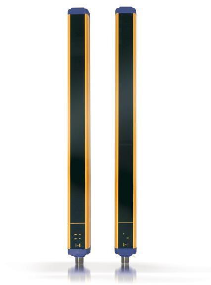
8 Some parts or sections of this manual containing important information for the user or installing operator are preceded by a note: Notes and detailed descriptions about particular characteristics of the safety devices in order to better explain their functioning. Special instructions regarding the installation process. This manual contains all the information necessary for the selection and operation of the safety devices. However, specialised knowledge not included in this technical description is required for the planning and implementation of a safety light curtain on a power-driven machine. As the required knowledge may not be completely included in this manual, we suggest the customer to contact Datalogic Technical Service for any necessary information relative to the functioning of the light curtains and the safety rules that regulate the correct installation (cfr. USER INTERFACE AND DIAGNOSTICS page 42). 1.2 PACKAGE CONTENTS Package contains the following objects: Receiver (RX) Emitter (TX) Quick Guide of safety light curtain Periodical checklist and maintenance schedule Mini-DVD with instruction manual and other documents 4 angled fixing brackets and specific fasteners 2 additional angled fixing brackets for models with heights included between 1200 and 1800 mm 8/74
9 1.3 NEW FEATURES COMPARED TO SE4-PLUS (EDM) With respect to SE4-PLUS (EDM) series, the safety light curtain series presents new important features: Higher operating distance Shorter response time (see cfr.technical DATA page 49) Range enlargement with 150 to 1800 mm controlled heights New profile compatible with SE accessories New fastening system with rotating brackets TEST line with reversed activation logics (active high) Advanced alignment for receiver and transmitter units Furthermore, has 2 selectable functions, i.e.: EDM function Manual/automatic Restart 9/74
 of the device is the minimum diameter that an opaque object must have in order to obscure at least one of the beams that constitute the")

10 1.4 HOW TO CHOOSE THE DEVICE There are at least three different main characteristics that should be considered when choosing a safety light curtain, after having evaluated the risk assessment Detection capability The detection capability (or resolution) of the device is the minimum diameter that an opaque object must have in order to obscure at least one of the beams that constitute the detection zone and to actuate the sensing device. The resolution is related to the part of the body to be protected. R=14 mm Finger protection R=30 mm Hand protection As shown in Fig 1 - page 10, the resolution only depends on the geometrical characteristics of the lenses, diameter and distance between centres, and is independent of any environmental and operating conditions of the safety light curtain. Fig 1 - Detection capability The resolution value is obtained applying the following formula: R = I + d where: I=Interaxes between two adjacent optics d=lens diameter 10/74
 SG4-14-015-OO-E/X SG4-30-015-OO-E/X 150 SG4-14-030-OO-E/X SG4-30-030-OO-E/X 300")

11 1.4.2 Height of the detection zone The controlled height is the height protected by the safety light curtain. Model 14mm Fig 2 - Detection Zone Model 30mm Controlled height Hp (mm) SG OO-E/X SG OO-E/X 150 SG OO-E/X SG OO-E/X 300 SG OO-E/X SG OO-E/X 450 SG OO-E/X SG OO-E/X 600 SG OO-E/X SG OO-E/X 750 SG OO-E/X SG OO-E/X 900 SG OO-E/X SG OO-E/X 1050 SG OO-E/X SG OO-E/X 1200 SG OO-E/X SG OO-E/X 1350 SG OO-E/X SG OO-E/X 1500 SG OO-E/X SG OO-E/X 1650 SG OO-E/X SG OO-E/X /74

12 1.4.3 Minimum installation distance The safety device must be positioned at a specific safety distance (Fig 3 - page 12). This distance must ensure that the dangerous area cannot be reached before the dangerous motion of the machine has been stopped by the Safety Control System. The safety distance depends on 4 factors, according to the EN ISO Standard: Response time of the ESPE (the time between the effective beam interruption and the opening of the OSSD contacts) Machine stopping time including Safety Control System computing and actuating time if present. ESPE resolution Approaching speed of the object to be detected Fig 3 - Installation distance (vertical positioning) The following formula is used for the calculation of the safety distance: S = K (t1 + t2) + C where: S = Minimum safety distance in mm K = Speed of the object, limb or body approaching the dangerous area in mm/sec t1 = Response time of the ESPE in seconds (see cfr.technical DATA page 49) t2 = Machine stopping time in seconds (including the Safety Control System) C = Additional distance based on the possibility to insert the body or one of body parts inside the dangerous area before the protective device trips. C=8 (R -14) for devices with resolution 40 mm C=850 mm for devices with resolution > 40 mm R = Resolution of the system K value is: 2000 mm/s if the calculated value of S is 500 mm 1600 mm/s if the calculated value of S is > 500 mm 12/74
 the distance between the dangerous area and the most distant optical beam must be equal to the value calculated")
13 When devices with > 40 mm resolution are used, the height of the top beam has to be 900 mm (H2) from machine supporting base while the height of the bottom beam has to be 300 mm (H1). If the safety light curtain must be mounted in a horizontal position (Fig 4 - page 13) the distance between the dangerous area and the most distant optical beam must be equal to the value calculated using the following formula: S = 1600 mm/s (t1 + t2) ,4 H where: S = Minimum safety distance in mm. t1 = Response time of the ESPE in seconds (cfr. TECHNICAL DATA page 49) t2 = Machine stopping time in seconds (including the Safety Control System) H = Beam height from ground; this height must always be less than 1,000 mm. Fig 4 - Installation distance (horizontal positioning) Practical examples Let's suppose to have a light curtain with height = 600 mm To calculate the distance of the device from the ESPE, in a vertical position, the following formula is used: S = K*T + C where: S t1 t2 T C R = Minimum safety distance in mm. = ESPE response time = Machine total stopping time (Including safety control system). = (t1 + t2) Overall system stopping performance = 8 * (R 14) for devices with resolution <= 40 mm = Resolution of the system In all cases, if K = 2000mm/sec then S will be > 500 mm. Distance will have then to be recalculated using K = 1600 mm/sec. SG OO-E/X SG OO-E/X T sec sec C 0 mm 128 mm S mm mm The reference standard is EN ISO Safety of machinery - Positioning of safeguards with respect to the approach speeds of parts of the human body. The following information is to be considered as indicative and concise. For correct safety distance please refer to complete standard EN ISO /74


14 1.5 TYPICAL APPLICATIONS Example 1: Operating point protection on drilling machines The operator positions the part and takes it back after machining. The operator must be protected against possible abrasions while working. Solution: SG 14mm safety light curtain is especially suitable for this kind of application, which requires the installation of the device directly on the machine. Advantages: Highly reduced profile size guarantees installation flexibility for machine dimensions. Fig 5 - Operating point protection on drilling machines Example 2: Bending presses The safety device must protect the operator from being squashed between the top and bottom tool or the machined part during the fast approach phase. Solution: If only one beam of the safety light curtain is darkened while the press is moving down, the mobile tool bar will stop. Advantages: The safety light curtain can be used in most bending operations thanks to its easy installation and compact dimensions. As well as offering excellent reliability, SG ensures increased plant productivity as it reduces the dead times necessary for machine accessing, adjustment and maintenance. Fig 6 - Bending presses 14/74


15 Example 3: Paper cutting machines These machines typically cut paper to a specific size for newspapers or special applications. The operator must be protected against abrasion or cuts by cutter blades. Solution: SG 30mm safety light curtain is especially suitable for this kind of application, which require the installation of the device directly on the machine. Advantages: Highly reduced profile and the two side slots ensure installation flexibility for machine dimensions. Fig 7 - Paper cutting machines Example 4: Milling machines A milling machine is a machine tool used for the shaping of metals and other solid materials. Operator hands and body must be protected from being dragged, entangled or cut by the tool / spindle. Solution: SG 30mm safety light curtain is the best solution considering the required safety levels and application type. When even just one of the light curtain beams is interrupted, the machine is immediately stopped. Advantages: Highly reduced profile size guarantees installation flexibility for machine dimensions. Fig 8 - Milling machines 15/74
16 1.6 SAFETY INFORMATION For a correct and safe use of the safety light curtains, the following points must be observed: The stopping system of the machine must be electrically controlled. This control system must be able to stop the dangerous movement of the machine within the total machine stopping time T as per paragraph Minimum installation distance page 12 and during all working cycle phases. Mounting and connection of the safety light curtain must be carried out by qualified personnel only, according to the indications included in the special sections (refer to sections INSTALLATION page 17, MECHANICAL MOUNTING page 26, ELECTRICAL CONNECTIONS page 27, ALIGNMENT PROCEDURE page 33) and in the applicable standards. The safety light curtain must be securely placed in a particular position so that access to the dangerous zone is not possible without the interruption of the beams (refer section INSTALLATION page 17). The personnel operating in the dangerous area must be well trained and must have adequate knowledge of all the operating procedures of the safety light curtain. Only for models SG4-xx-xxx-OO-E: The TEST button must be located outside the protected area because the operator must check the protected area during all Test operation. The RESET/RESTART button must be located outside the protected area because the operator must check the protected area during all Reset/Restart operations. Please carefully read the instructions for the correct functioning before powering the light curtain on. 16/74
17 2 INSTALLATION 2.1 PRECAUTIONS TO BE OBSERVED FOR THE CHOICE AND INSTALLATION Make sure that the protection level assured by the light curtain device is compatible with the real danger level of the machine to be controlled, according to EN ISO : 2015 or EN 62061:2005/A2: Use only matched emitter and receiver pairs with same serial no. The outputs (OSSD) of the ESPE must be used as machine stopping devices and not as command devices. The machine must have its own START command. The dimension of the smallest object to be detected must be larger than the resolution level of the device. The ESPE must be installed in an environment complying with the characteristics indicated in TECHNICAL DATA page 49. The ESPE must not be installed close to strong and/or flashing light sources, in particular close to the front window of receiving unit. The presence of intense electromagnetic disturbances could affect device s correct operation. This condition shall be carefully assessed with the advice of DATALOGIC Technical Service. The operating distance of the device can be reduced in presence of smog, fog or airborne dust. A sudden change in environment temperature, with very low minimum peaks, can generate a small condensation layer on the lenses and thus jeopardize correct operation. 17/74


18 2.2 GENERAL INFORMATION ON DEVICE POSITIONING The safety light curtain should be carefully positioned in order to provide the necessary protection. Access to the dangerous area must only be possible by passing through the protecting safety light beams. Fig 9 - page 18 shows some examples of possible access to the machine from the top and the bottom sides. These situations may be very dangerous and so the installation of the safety light curtain at sufficient height in order to completely cover the access to the dangerous area (Fig 10 - page 18) becomes necessary. Fig 9 - Wrong light curtain positioning Fig 10 - Correct light curtain positioning If the operator is able to enter in the dangerous area, an additional mechanical protection must be mounted to prevent the access. Under standard operating conditions, machine starting must not be possible while operators are inside the dangerous area. Where it is not possible to install safety light curtain very near to the dangerous zone, a second light curtain must be mounted in a horizontal position in order to prevent any lateral access, as shown in Fig 12 - page 18. Fig 11 - Wrong light curtain positioning Fig 12 - Correct light curtain positioning 18/74

19 2.2.1 Minimum distance from reflecting surfaces Reflecting surfaces placed near the light beams of the safety device (over, under or laterally) can cause passive reflections. These reflections can affect the recognition of an object inside the controlled area. Moreover, if the RX receiver detects a secondary beam (reflected by the side-reflecting surface) the object might not be detected, even if the object interrupts the main beam. Fig 13 - Distance from reflecting surfaces It is important to position the safety light curtain according to the minimum distance from reflecting surfaces. The minimum distance depends on: operating distance between emitter (TX) and receiver (RX); real aperture angle of ESPE (EAA); especially: 19/74
20 for ESPE Type 4 EAA = 5 (α = ± 2.5 ) Fig 14 - Minimum distance from reflective surface The formula to get Dsr is the following: For ESPE Type 4: Dsr (m) = 0.13 Dsr (m) = 0.5 x operating distance (m) x tg 2a for operating distance < 3 m for operating distance >= 3 m 20/74
21 2.2.2 Distance between homologous devices The following graphic shows the distance from the interfering devices (Ddo) according to the operating distance (Ddo) of the couple ( TXA RXA ). If different safety devices have to be installed in adjacent areas, the emitter of one device must not interfere dangerously with the receiver of the other device. The TXB interfering device must be positioned outside a minimum Ddo distance from the TXA RXA emitterreceiver couple axis. Fig 15 - Distance between homologous devices This minimum Ddo distance depends on: the operating distance between emitter (TXA) and receiver (RXA) the effective aperture angle of the ESPE (EAA) Fig 16 - ESPE Type4 The following table shows, for convenience, the values of the minimum installation distances relative to some operating distances: Operating distance (m) Minimum installation distance (m) 3 0,3 6 0,4 10 0,5 19 0,6 The interfering device (TXB) must be positioned at the same Ddo distance, calculated as shown above, even if closer to TXA respect to RXA. Installation precautions have to be taken to avoid interference between homologous devices. A typical situation is represented by the installation areas of several adjacent safety devices aligned one next to the other, for example in plants with different machines. 21/74
22 The figure provides two examples: Fig 17 - Recommended positioning for homologous devices If two light curtains have to be mounted near each other as reported in the first example of Fig 17 - page /74

23 2.2.3 Emitter and Receiver Orientation The two units shall be assembled parallel each other, with the beams arranged at right angles with the emission and receiving surface, and with the connectors pointing to the same direction. The configurations shown in the figure must be avoided: Fig 18 - Wrong light curtain TX-RX orientations 23/74

24 2.2.4 Use of deviating mirrors The control of any dangerous area, with several but adjacent access sides, is possible using only one safety device and well-positioned deviating mirrors. The figure shows a possible solution to control two different access sides, using one mirror placed at 45 with respect to the beams. Fig 19 - Use of deviating mirrors The operator must respect the following precautions when using the deviating mirrors: The alignment of the emitter and the receiver can be a very critical operation when deviating mirrors are used. Even very small displacements of the mirror is enough to lose alignment. The use of DATALOGIC laser pointer accessory is recommended under these conditions. The minimum safety distance (S) must be respected for each single section of the beams. The effective operating range decreases by about 20% by using only one deviating mirror. The following table shows estimated operating distances relating to the number of mirrors used. Number of mirrors Operating Distance (14mm) Operating Distance (30mm) m 19 m m 15.2 m The presence of dust or dirt on the reflecting surface of the mirror causes a drastic reduction in the range. 24/74

25 2.2.5 Controls after first installation The control operations to carry-out after the first installation and before machine start-up are listed hereinafter. The controls must be carried-out by qualified personnel, either directly or under the strict supervision of the person in charge of machinery Safety. Verify that: ESPE remains blocked ( lit RED) intercepting the beams along the protected area using the specific test piece, following the scheme in Fig 20 - page 25. Fig 20 - Path of the test piece TP-14 for light curtains with 14 mm resolution:sg4-14-xx-x TP-30 for light curtains with 30 mm resolution:sg4-30-xx-x ESPE has to be correctly aligned, press slightly on the product side in both directions the red LED must not turn on. The response time at machine STOP, including the ESPE and machine response times, must be included in the limits defined in the calculation of the safety distance (refer to cfr.installation page 17). The safety distance between the dangerous parts and ESPE must comply with the requirements indicated in cfr..installation page 17). A person must not access or remain between ESPE and the dangerous parts of the machine. Access to the dangerous areas of the machine must not be possible from any unprotected area. ESPE must not be disturbed by external light sources, ensuring that it remains in Normal operating function for at least minutes and placing the specific test piece in the protected area in the SAFE condition for the same period. Verify the correspondence of all the accessory functions, activating them in the different operating conditions. Only for SG4-xx-xxx-OO-E models: The activation of the TEST function causes the opening of the OSSD outputs (red LED on and controlled machine stop). 25/74
.")
.")
26 3 MECHANICAL MOUNTING The emitting (TX) and receiving (RX) units must be installed with the relevant sensitive surfaces facing each other. The connectors must be positioned on the same side and the distance must be included within the operating range of the model used (see cfr.technical DATA page 49). The two units shall be positioned so as to be aligned and parallel as much as possible. The next step is the fine alignment, as shown in chapter ALIGNMENT PROCEDURE page 33. Two types of brackets can be used to fix the two units: Angled fixing brackets are supplied with all models (Fig 21 - page 26). Adjustable supports for correcting unit inclination on the axes are available on request (see cfr.accessories page 54). Fig 21 - Angle brackets Rotating brackets (Fig 22 - page 26), available upon request, can be used as an alternative or together with angled brackets. For fixing with rotating bracket, refer to Fig 23 - page 27. Fig 22 - Rotating brackets 26/74

27 Anti-vibration shock absorbers together with fixing brackets are recommended in applications with particularly strong vibrations to reduce the impact of the vibrations. Fig 23 - Fixing brackets Fig 23 - page 27 and table below show the recommended mounting positions according to the safety light curtain length. Fig 24 - Dimensions (mm) VERSION L (mm) A (mm) B (mm) C (mm) /74
28 4 ELECTRICAL CONNECTIONS 4.1 PIN-OUT AND CONFIGURATION PIN CONNECTION MODELS SG4-xx-xxx-OO-X All electrical connections to the emitting and receiving units are made through a male M12 connector, located on the lower part of the two units. For receiver a M12 5-poles connector is used, while for emitter a M12 4-poles connector is used. RECEIVER (RX): Fig 25 - Receiver 1 = brown = +24 VDC 2 = white = OSSD1 3 = blue = 0 V 4 = black = OSSD2 5 = grey = NOT USED EMITTER (TX): Fig 26 - Emitter 1 = brown = +24 VDC 2 = white = NOT USED 3 = blue = 0 V 4 = black = NOT USED 28/74
29 4.1.2 MODELS SG4-xx-xxx-OO-E All electrical connections to the emitting and receiving units are made through a male M12 connector, located on the lower part of the two units. For receiver a M12 8-pole connector is used, while for emitter a M12 4-pole connector is used. RECEIVER (RX): Fig 27 - Receiver 1 = white = RESET/RESTART (*) 2 = brown = +24 VDC 3 = green = EDM SELECTION 4 = yellow = EDM 5 = grey = OSSD1 6 = pink = OSSD2 7 = blue = 0 V 8 = red = MANUAL/AUTOMATIC RESTART (*) automatic RESTART --> RESET function manual RESTART --> RESET / RESTART function To set manual restart, connect Pin 8 (MAN/AUTO) with Pin 6 (OSSD2). To set automatic restart, connect Pin 8 (MAN/AUTO) with Pin 5 (OSSD1). To deactivate EDM function, connect Rx Pin 3 to 24VDC on Receiver. EMITTER (TX): Fig 28 - Emitter 1 = brown = +24 VDC 2 = white = TEST 3 = blue = 0 V 4 = black = NOT USED 29/74
30 Function Connection to Status TEST RESET SELECT RANGE EDM ENABLE EDM MAN/AUTO RESTART SELECTION +24 VDC Not connected or 0V +24 VDC Not connected or 0V +24 VDC Not connected or 0V Normally closed contact for a force-guided relay +24 VDC Not connected or 0V OSSD1 OSSD2 TEST ON TEST OFF RESET ON RESET OFF SHORT (9 m) LONG (19 m) - EDM OFF EDM ON AUTOMATIC RESTART MANUAL RESTART 30/74
31 4.2 NOTES ON CONNECTIONS For the correct operation of the safety light curtains, the following precautions regarding the electrical connections have to be respected: Do not place connection cables in contact with or near high-voltage cables and/or cable undergoing high current variations (e.g. motor power supplies, inverters, etc.). Do not connect in the same multi-pole cable the OSSD wires of different light curtains. Only fori SG4-xx-xxx-OO-E models: The TEST wire must be connected through a N.O. button to the supply voltage of the ESPE. The RESET/RESTART wire must be connected through a N.O. button to the supply voltage of the ESPE. The TEST button must be located in such a way that the operator can check the protected area during any test (see cfr.function SETTING page 36). The RESET/RESTART button must be located in such a way that the operator can check the protected area during any reset operation (see cfr.function SETTING page 36). The device is already equipped with internal overvoltage and overcurrent suppression devices. The use of other external components is not recommended. Example: connection to the safety relay SE-SR2 Fig 29 - Connection to SE-SR2 Safety Relais The figures show the connection between the safety light curtains and the safety relay of the SE-SR2 series functioning in the Automatic Restart mode (left side) and Manual Restart with monitoring (right side). Do not use varistors, RC circuits or LEDs in parallel at relay inputs or in series at OSSD outputs. The OSSD1 and OSSD2 safety contacts cannot be connected in series or in parallel, but can be used separately, conforming to the plant s safety requirements. If one of these configurations is erroneously used, the device enters into the output failure condition (see cfr.user INTERFACE AND DIAGNOSTICS page 42). 31/74
32 Connect both OSSDs to the device to control. Failure to connect an OSSD to the activating device jeopardizes the system safety degree that the light curtain has to control. Fig 30 - OSSDs connection Fig 31 - Behaviour of OSSDs 32/74

33 4.3 EARTH CONNECTION Safety light curtain units are preset for easy ground connection. A special compartment, positioned onto caps and marked with the special symbol shown in Fig 32 - page 33, allows connection with ground cable by means of an additional screw coming with the equipment. Fig 32 - Ground connection configuration Ground connection configuration is the most common and guarantees the best immunity against electromagnetic disturbances. Safety light curtain can function even without ground connection. This condition has to be carefully evaluated according to the EMC disturbance immunity and necessary insulation class considering the plant or entire system where the light curtain is installed. The ground connection of the two units is not necessary for Class III, while the use of a duly-insulated lowvoltage feeder type SELV or PELV is compulsory. In this case, we recommend covering the earth symbol present on the caps of the two units with a blank sticker. The ground connection of the two units is compulsory for Class I, while the use of a duly-insulated feeder type SELV or PELV is not compulsory but anyway recommended. The following table is a summary of SG2-E electrical protections. Electrical protections Class I Class III Ground Connection Compulsory Not necessary Ground connection symbol Compulsory Not necessary Power supply by generators SELV / PELV Recommended Compulsory 33/74


34 5 ALIGNMENT PROCEDURE The alignment between the emitting and the receiving units is necessary to obtain the correct operation of the light curtain. A good alignment prevents outputs instability caused by dust or vibrations. The alignment is perfect if the optical axes of the first and the last emitting unit's beams coincide with the optical axes of the corresponding elements of the receiving unit. The beam used to synchronise the two units is the first after the connector. SYNC is the optics connected with this beam and LAST is the optics connected to the last beam after the SYNC unit. Fig 33 - Signals are clearly identified through symbols allowing immediate reading, independent of bars directions. A short description of the signalling LEDs is necessary to avoid misunderstandings. Fig 34 - Receiver & Emitter 34/74
35 5.1 CORRECT ALIGNMENT PROCEDURE The light curtain alignment can be effected only after having completed the mechanical installation and the electrical connections as described above. Compare alignment results with those given in the following table: SG4-xx-xxx-OO-X: Display LED NORMAL OP. ON ON ON LED SAFE (BREAK) OFF OFF OFF Condition Each beam is over the min. operating threshold and the number of beam over the threshold is included between 25 and 50% Each beam is over the min. operating threshold and the number of beam over the threshold is included between 50 and 75% Each beam is over the min. operating threshold and the number of beam over the threshold is included between 75 and 100% Alignment status MAXIMUM Ensure that the green LED ( NORMAL OP.) is steady ON. a. Delimit the area in which the green LED (( ) is steady through some micro adjustments - for the first and then for the second unit - so to have the maximum alignment (4) and then place both units in the centre of this area. b. Fix the two units firmly using brackets. Verify that the green LED ( ) on the RX unit is ON and beams are not interrupted, then verify that the red LED SAFE (BREAK) turns ON if even one single beam is interrupted (condition where an object has been detected).this verification shall be made with the special cylindrical Test Piece having a size suitable to the resolution of the device used (refer cfr.controls after first installation page 24. c. Switch OFF and ON the device in normal operating mode. The alignment level is monitored also during device standard operating mode via display (see cfr.diagnostic messages page 42) Once the curtain has been aligned and correctly fastened, the display signal is useful both to check the alignment and show a change in the environmental conditions (occurrence of dust, light disturbance and so on) via signal level monitoring. 35/74
 LED yellow SYNC LED yellow LAST OFF ON ON ON OFF ON OFF ON SYNC NOK LAST NOK SYNC OK LAST NOK SYNC OK LAST OK Condition Alignment status Not aligned Not aligned OFF ON OFF OFF MIDDLE")


 is OFF.")
36 SG4-xx-xxx-OO-E: Display LED NORMAL OP. LED SAFE (BREAK) LED yellow SYNC LED yellow LAST OFF ON ON ON OFF ON OFF ON SYNC NOK LAST NOK SYNC OK LAST NOK SYNC OK LAST OK Condition Alignment status Not aligned Not aligned OFF ON OFF OFF MIDDLE OPTICS NOK Not aligned ON OFF OFF OFF ON OFF OFF OFF ON OFF OFF OFF ON OFF OFF OFF Each beam is over the min. operating threshold and the number of beam over the threshold is included between 0 and 25% Each beam is over the min. operating threshold and the number of beam over the threshold is included between 25 and 50% Each beam is over the min. operating threshold and the number of beam over the threshold is included between 50 and 75% Each beam is over the min. operating threshold and the number of beam over the threshold is included between 75 and 100% MINIMUM align. - - MAXIMUM align. a. Keep the receiver in a steady position and set the emitter until the yellow LED ( SYNC) is OFF. This condition shows the alignment of the first synchronisation beam. b. Rotate the emitter, pivoting on the lower optics axis, until the yellow LED ( LAST) is OFF. Ensure that the green LED ( NORMAL OP.) is steady ON. c. Delimit the area in which the green LED ( ) is steady through some micro adjustments - for the first and then for the second unit - so to have the maximum alignment (4) and then place both units in the centre of this area. d. Fix the two units firmly using brackets. Verify that the green LED ( ) on the RX unit is ON and beams are not interrupted, then verify that the red LED SAFE (BREAK) turns ON if even one single beam is interrupted (condition where an object has been detected). This verification shall be made with the special cylindrical Test Piece having a size suitable to the resolution of the device used (refer cfr.controls after first installation page 24). e. Switch OFF and ON the device in normal operating mode. The alignment level is monitored also during device standard operating mode via display (cfr.user INTERFACE AND DIAGNOSTICS page 42). Once the curtain has been aligned and correctly fastened, the display signal is useful both to check the alignment and show a change in the environmental conditions (occurrence of dust, light disturbance and so on) via signal level monitoring. 36/74
37 6 FUNCTIONS SETTING 6.1 RESET MODE SG4-xx-xxx-OO-E models: The interruption of a beam due to an opaque object causes the opening of OSSD outputs and the stop of the safety light curtain SAFE (BREAK) condition. ESPE standard operation can be reset (OSSD safety contact closing = NORMAL OP. condition different ways: Carefully assess risk conditions and reset modes. In applications protecting access to dangerous areas, the automatic reset mode is potentially unsafe if it allows the operator to pass completely beyond the sensitive area (see Fig 12 - page 18). In this case, the reset, using for example the manual reset of the SE-SR2 relay, (cfr.notes on connections page Errore. Il segnalibro non è definito. might be necessary. ) in two Automatic restart - After its activation ESPE resets to standard operating condition once the object has been removed from the controlled area. Manual restart - After its activation ESPE resets to standard operating condition only once the reset function has been enabled and provided that the object has been removed from the controlled area. This condition, called interlock, is signalled on the display (see cfr.user INTERFACE AND DIAGNOSTICS page 42). Time chart (Manual Restart) Fig 35 - Time chart (Manual Restart) The automatic or manual restart can be selected by connecting the receiver (see cfr.electrical CONNECTIONS page 27). 37/74
38 7 FUNCTIONS This chapter deals with all the functions of the light curtain. 7.1 TEST The TEST function can be activated by keeping a normally open external contact (TEST push-button), open for at least 0.5 seconds. The TEST signal is active high. Fig 36 - Test timings 38/74
39 7.2 RESET The RX light curtain has a RESET function which is activated after an internal error. The reset can be made only in case of optical error, OSSD error EDM or manual/automatic restart selection (see cfr.user INTERFACE AND DIAGNOSTICS page 42). The RESET function can be activated by keeping a normally open external contact (RESET/RESTART pushbutton), open for at least 5 seconds. The RESET signal is active high. Fig 37 - Reset timings 39/74
40 7.3 EDM The light curtain has a function for monitoring actuation external devices (EDM). This function can be enabled or deactivated. EDM enabled: Disconnect or connect to the ground pin 3 of receiver M12 8-pole connector (EDM enabling = ON). Connect EDM input (pin 4 of M12 8-pole - RX) to a 24 VDC normally closed contacts of the device to be monitored. Fig 38 - The decimal dot on the display shows that the function is enabled. EDM deactivated: Connect to 24 VDC pin 3 of receiver M12 8-pole connector (EDM enabling = OFF). Disconnect or connect to the ground EDM input (pin 4 of M12 8-pole - RX). This function checks normally closed contact switch on OSSD status change. Fig 39 - OSSD status TC >= 350 msec: 350 msec: time after OSSD OFF-ON switch when EDM test is performed. T0 >= 100 msec: time after OSSD ON-OFF switch when EDM test is performed. 40/74
41 7.4 ALIGNMENT AID FUNCTION Light curtain is equipped with a system which informs the operator on the alignment obtained. The alignment function can be activated when powering the device, by keeping the normally open RESET/RESTART contact closed for at least 0.5 seconds (see Fig 30 - page 32). Fig 40 - When the best alignment has been reached, restart the device to return to the standard operating mode, by powering off and on again the Rx unit. The alignment level is monitored also during device standard operating mode via display (see cfr.user INTERFACE AND DIAGNOSTICS page 42). Once the curtain has been aligned and correctly fastened, the display signal is useful both to check the alignment and show any changes in the environmental conditions (occurrence of dust, light disturbance and so on). OSSDs are not active on the alignment mode. 41/74

42 8 USER INTERFACE AND DIAGNOSTICS 8.1 USER INTERFACE Curtain operating status is displayed onto a 1-digit display both on receiver and emitter. Light curtain also has four LEDs on the receiver and two LEDs on the emitter. Fig 41 - page 42 shows all signalling LEDs modes: OFF, ON and BLINKING. Fig 41 - Signalling LEDs 42/74
43 8.2 DIAGNOSTIC MESSAGES The operator can evaluate the main causes of the system stop or failure through the display and signalling LEDs. Diagnostic messages SG4-xx-xxx-OO-X models For Receiver: Function State Meaning LED DIGIT Emission (OSSD ON) (green ON) Light curtain working in normal operating conditions Normal operation Interruption (OSSD OFF) (red ON) Light curtain working in safety block conditions. Error status Signal level Minimum (1 bar) Medium (2 bar) Maximum (3 bar) Function Type Check and repair LED DIGIT Check OSSD connections. Make sure that OSSD error they are not in contact with one another or (red ON) with the supply cables, then Reset. If the failure continues contact DATALOGIC. Internal error (red ON) Switch OFF and switch ON the power supply circuit. If the failure continues contact DATALOGIC. Optical error (red ON) Reset. If the failure continues contact DATALOGIC. For Emitter: Function State Meaning LED DIGIT Normal operation Emission (green ON yellow ON) Light curtain in normal operating condition Function Type Check and repair LED DIGIT Internal error I (green ON) Switch OFF and switch ON the power supply circuit. If the failure continues contact DATALOGIC. Error status Optical error (green ON) No power supply (LEDs OFF) Switch OFF and switch ON the power supply circuit. If the failure continues contact DATALOGIC. Check connections and input voltage correct value. If the failure continues contact DATALOGIC. 43/74
 (green ON) Interruption (OSSD OFF) (red ON) Interlock Beams free (red ON yellow ON) Interlock Beams interrupted (red ON")

 with the supply cables, then Reset. If the failure continues contact DATALOGIC.")
 Restart selection error (red ON) No power supply (LEDs OFF) Check EDM connections and lines.")
44 Diagnostic messages SG4-xx-xxx-OO-E models For Receiver: Function State Meaning LED DIGIT Alignment See ALIGNMENT PROCEDURE page 33 TEST (red ON) Light curtain being tested. OSSD status shall be OFF Normal operation Emission (OSSD ON) (green ON) Interruption (OSSD OFF) (red ON) Interlock Beams free (red ON yellow ON) Interlock Beams interrupted (red ON yellow ON) Signal level Light curtain working in normal operating conditions Light curtain working in safety block conditions. Light curtain in interlock, waiting for restart. OSSD status must be OFF Light curtain in interlock. OSSD status must be OFF Minimum (1 bar) Medium (2 bar) Maximum (3 bar) EDM enabled EDM function is selected - Function Type Check and repair LED DIGIT Check OSSD connections. Make sure that Error status OSSD error they are not in contact with one another or (red ON) with the supply cables, then Reset. If the failure continues contact DATALOGIC. Internal error (red ON) Switch OFF and switch ON the power supply circuit. If the failure continues contact DATALOGIC. Optical error (red ON) Reset. If the failure continues contact DATALOGIC. EDM error (red ON) Restart selection error (red ON) No power supply (LEDs OFF) Check EDM connections and lines. If the failure continues contact DATALOGIC. Check the man/auto restart connection. If the failure continues contact DATALOGIC. Check connections and input voltage value. If the failure continues contact DATALOGIC. 44/74
 Switch")
 No power supply (LEDs OFF) Switch Check connections and input voltage correct value.")
45 For Emitter: Function State Meaning LED DIGIT Normal operation TEST (green ON) Emission (green ON yellow ON) Light curtain being tested. OSSD status on the receiver must be OFF Light curtain in normal operating condition Function Type Check and repair LED DIGIT Internal error (green ON) Switch OFF and switch ON the power supply circuit. If the failure continues contact DATALOGIC. Error status Optical error (green ON) No power supply (LEDs OFF) Switch OFF and switch ON the power supply circuit. If the failure continues contact DATALOGIC. Check connections and input voltage correct value. If the failure continues contact DATALOGIC. 45/74
46 9 PERIODICAL CHECKS The following is a list of recommended check and maintenance operations that should be periodically carried-out by qualified personnel (cfr. Controls after first installation page 24) Check that: The ESPE stays locked ( ) during beam interruption along the entire protected area, using the suitable Test Piece (according to the Fig 20 - page 25 scheme). The ESPE is correctly aligned. Press slightly product side, in both directions and the red LED must not turn ON. The response time upon machine STOP (including response time of the ESPE and of the machine) is within the limits defined for the calculation of the safety distance (see cfr.installation page 17). The safety distance between the dangerous areas and the ESPE are in accordance with the instructions included in INSTALLATION page 17. Access of a person between ESPE and machine dangerous parts is not possible nor is it possible for him/her to stay there. Access to the dangerous area of the machine from any unprotected area is not possible. The ESPE and the external electrical connections are not damaged. The frequency of checks depends on the particular application and on the operating conditions of the safety light curtain. 46/74
47 9.1 GENERAL INFORMATION AND USEFUL DATA Safety MUST be a part of our conscience. The safety devices fulfil their safety function only if they are correctly installed, in accordance with the Standards in force. If you are not certain to have the expertise necessary to install the device in the correct way, DATALOGIC is at your disposal to carry out the installation. The device uses fuses that are not self-resetting. Consequently, in presence of short-circuits causing the cut-off of these fuses, both safety light curtains (RX and TX) shall be sent to DATALOGIC Repair Service Department. A power failure caused by interferences may cause the temporary or trigger Safety State over connected safety Fieldbus, but the safe functioning of the light curtain will not be compromised. 9.2 WARRANTY The warranty period for this product is 36 months. See the General Terms and Conditions of Sales at for further details. DATALOGIC will not be liable for any damages to persons and things caused by the non-observance of the correct installation modes and device use. In presence of a non-functioning device, always return the emitting and receiving units for repair or replacement. 47/74
48 10 DEVICE MAINTENANCE DATALOGIC safety light curtains do not require special maintenance operations. To avoid the reduction of the operating distance, optic protective front surfaces must be cleaned at regular intervals. Use soft cotton cloths damped in water. Do not apply too much pressure on the surface in order to avoid making it opaque. Please do not use on plastic surfaces or on light curtain painted surfaces: alcohol or solvents wool or synthetic cloths paper or other abrasive materials 10.1 PRODUCT DISPOSAL Under current Italian and European laws, DATALOGIC is not obliged to take care of product disposal at the end of its life. DATALOGIC recommends to dispose of the product in compliance with local laws or contact authorised waste collection centres. 48/74
49 11 TECHNICAL DATA SAFETY CATEGORY: Type 4 (rif. EN : 2013) SIL 3 (rif. EN 61508) SIL CL 3 (ref. EN 62061:2005/A2: 2015) PL e, Cat. 4 (rif. EN ISO : 2015) PFHd [1/h] = 2,64E-09 MTTFd [years] = 444 ELECTRICAL DATA Power supply (Vdd): 24 VDC ± 20% Consumption (TX): 2.5 W max Consumption (RX): 3.5 W max (without load) Outputs: 2 PNP Short-circuit protection: 1.4 A max Output current: 0.5 A max su ciascuna uscita Output voltage status ON: Vdd 1 V min Output voltage status OFF: 0.2 V max Capacitive load: Vcc max Response times: see chapter AVAILABLE MODELS AND RESPONSE TIMES page 50 Controlled height: mm Auxiliary functions: Reset / Test / EDM Electrical protection: Classe I / Classe III (see chapter ELECTRICAL CONNECTIONS page 27) Connections: for receiver: M12 5-pole (SG4-xx-xxx-OO-X) M12 8-pole (SG4-xx-xxx-OO-E) for emitter: M12 4-pole Cables length (for power supply): 50 m. max OPTICAL DATA Emitting light (λ): Infrared, LED (950 nm) Resolution: mm Operating distance: m per 30 mm m per 14 mm Ambient light rejection: EN : 2013 MECHANICAL AND ENVIRONMENTAL DATA Operating temperature: C Storage temperature: C Temperature class: T6 Humidity: % (no condensation) Mechanical protection: IP 65 EN Vibrations: Width 0.35 mm, Frequency Hz 20 sweep per axis, 1octave/min EN Shock resistance: 16 ms (10 G) 1,000 shocks per axis EN Housing material: Painted aluminium (yellow RAL 1003) Front side material: PMMA Cover material: PC LEXAN Weight: 1.35 kg per linear meter for single unit 49/74
50 12 AVAILABLE MODELS Model Controlled height (mm) No. Beams Response time (msec) Resolution (mm) SG OO-E/X SG OO-E/X SG OO-E/X SG OO-E/X SG OO-E/X SG OO-E/X SG OO-E/X SG OO-E/X SG OO-E/X SG OO-E/X SG OO-E/X SG OO-E/X SG OO-E/X SG OO-E/X SG OO-E/X SG OO-E/X SG OO-E/X SG OO-E/X SG OO-E/X SG OO-E/X SG OO-E/X SG OO-E/X SG OO-E/X SG OO-E/X /74
51 Product PL CAT SIL SIL CL PFHd (1/h) T1 (years ) MTTFd (years) DC SFF HFT SG OO-E/X e ,64E ,80% 99,30% 1 SG OO-E/X e ,64E ,80% 99,30% 1 SG OO-E/X e ,64E ,80% 99,30% 1 SG OO-E/X e ,64E ,80% 99,30% 1 SG OO-E/X e ,64E ,80% 99,30% 1 SG OO-E/X e ,64E ,80% 99,30% 1 SG OO-E/X e ,64E ,80% 99,30% 1 SG OO-E/X e ,64E ,80% 99,30% 1 SG OO-E/X e ,64E ,80% 99,30% 1 SG OO-E/X e ,64E ,80% 99,30% 1 SG OO-E/X e ,64E ,80% 99,30% 1 SG OO-E/X e ,64E ,80% 99,30% 1 SG OO-E/X e ,64E ,80% 99,30% 1 SG OO-E/X e ,64E ,80% 99,30% 1 SG OO-E/X e ,64E ,80% 99,30% 1 SG OO-E/X e ,64E ,80% 99,30% 1 SG OO-E/X e ,64E ,80% 99,30% 1 51/74
52 13 OVERALL DIMENSIONS Fig 42 - Dimensions (mm) MODEL 14mm MODEL 30mm L1 (mm) L2 (mm) SG OO-E/X SG OO-E/X SG OO-E/X SG OO-E/X SG OO-E/X SG OO-E/X SG OO-E/X SG OO-E/X SG OO-E/X SG OO-E/X SG OO-E/X SG OO-E/X SG OO-E/X SG OO-E/X SG OO-E/X SG OO-E/X SG OO-E/X SG OO-E/X SG OO-E/X SG OO-E/X SG OO-E/X SG OO-E/X SG OO-E/X SG OO-E/X /74
53 14 INCLUDED ACCESSORIES Metal angled fixing bracket (ST-KSTD) MODEL DESCRIPTION ST-KSTD Angled fixing bracket (4 pcs kit) Fig 43 - Dimensions (mm) 53/74
54 15 ACCESSORIES (dimensions in mm) 15.1 (ST-KSTD) METAL ANGLED FIXING BRACKET MODEL DESCRIPTION CODE ST-KSTD Angled fixing bracket (4 pcs kit) 95ACC1670 Fig 44 - ST-KSTD 54/74
 95ACC1680 ST-K6OR Orientable supports (6 pcs kit) 95ACC1690 ST-K4AV Antivibration supports (4 pcs kit) 95ACC1700 ST-K6AV")

55 Angled fixing bracket mounting with orientable and antivibration supports MODEL DESCRIPTION CODE ST-K4OR Orientable supports (4 pcs kit) 95ACC1680 ST-K6OR Orientable supports (6 pcs kit) 95ACC1690 ST-K4AV Antivibration supports (4 pcs kit) 95ACC1700 ST-K6AV Antivibration supports (6 pcs kit) 95ACC1710 Fig 45 - Angled fixing bracket Fig 46 - Angled fixing bracket + Orientable support Fig 47 - Angled fixing bracket + Antivibration support Fig 48 - Angled fixing bracket + Orientable support + Antivibration support 55/74
56 15.2 (ST-KPXMP) PLASTIC ANGLED FIXING BRACKET MODEL DESCRIPTION CODE ST-KP4MP Angled fixing bracket (4 pcs kit) 95ASE1100 ST-KP6MP Angled fixing bracket (6 pcs kit) 95ASE1110 Fig 49 - ST-KPxMP 56/74
57 Angled fixing bracket mounting with orientable and antivibration supports MODEL DESCRIPTION CODE ST-K4OR Orientable supports (4 pcs kit) 95ACC1680 ST-K6OR Orientable supports (6 pcs kit) 95ACC1690 ST-K4AV Antivibration supports (4 pcs kit) 95ACC1700 ST-K6AV Antivibration supports (6 pcs kit) 95ACC1710 Fig 50 - Angled fixing bracket Fig 51 - Angled fixing bracket + Orientable support Fig 52 - Angled fixing bracket + Antivibration support Fig 53 - Angled fixing bracket + Orientable support + Antivibration support 57/74
58 15.3 (ST-K4ROT) METAL ROTATING FIXING BRACKET MODEL DESCRIPTION CODE ST-K4ROT Rotating fixing bracket (4 pcs kit) 95ACC1280 Fig 54 - Dimensions (mm) 58/74
59 15.4 (SG-PSB) PROTECTIVE STANDS MODEL DESCRIPTION L (mm) CODE SG-PSB 600 Protective stand H=600 mm ASE2240 SG-PSB 1000 Protective stand H=1000 mm ASE2250 SG-PSB 1200 Protective stand H=1200 mm ASE2260 SG-PSB 1650 Protective stand H=1650 mm ASE2270 SG-PSB 1900 Protective stand H=1900 mm ASE2280 Mounting kit Fig 55 - Dimensions (mm) MODEL DESCRIPTION CODE ST-PS4-SG-SE Mounting kit (4 pcs kit) 95ASE1750 ST-PS6-SG-SE Mounting kit (6 pcs kit) 95ASE1760 Fig 56 - Fixing kit 59/74
60 15.5 (SG-P) PLATE KIT FOR PROTECTIVE STANDS MODEL DESCRIPTION CODE SG-P Plate kit with springs 95ASE2290 Mounting with SG-PSB Fig 57 - Dimensions (mm) Fig 58 - Mounting 60/74
61 15.6 (SE-S) COLUMNS AND FLOOR STANDS MODEL DESCRIPTION L(mm) X (mm) CODE SE-S 800 Column and floor stand H= 800 mm x30 95ACC1730 SE-S 1000 Column and floor stand H= 1000 mm x30 95ACC1740 SE-S 1200 Column and floor stand H= 1200 mm x30 95ACC1750 SE-S 1500 Column and floor stand H= 1500 mm x45 95ACC1760 SE-S 1800 Column and floor stand H= 1800 mm x45 95ACC1770 Fig 59 - Dimensions (mm) 61/74
62 15.7 (SG-DM) DEVIATING MIRRORS MODEL DESCRIPTION L1 (mm) L2 (mm) L3 (mm) CODE SG-DM 600 Deviating mirror version 600 mm ASE1680 SG-DM 900 Deviating mirror version 900 mm ASE1690 SG-DM 1200 Deviating mirror version 1200 mm ASE1700 SG-DM 1650 Deviating mirror version 1650 mm ASE1710 SG-DM 1900 Deviating mirror version 1900 mm ASE1720 Fig 60 - Dimensions ( mm) The image includes the mirror SG-DM and a mounting kit ST-DM. MODEL DESCRIPTION CODE SG-DM 150 Deviating mirror version 150 mm 95ASE1670 Fig 61 - SG-DM 150 Dimensions (mm) The image includes the mirror SG-DM and a mounting kit ST-DM. 62/74
 MODEL DESCRIPTION CODE ST-PS-DM Deviating mirror SG-DM mounting kit (2 T-nuts) 95ASE1770 Fig 63 - Mounting kit For each SG-DM mirror order 1 mounting kit")
63 Mounting kit for SG-DM with SE-S column and floor stands MODEL DESCRIPTION CODE ST-DM SG-DM mounting kit (2 pcs kit) 95ASE1940 Fig 62 - Mounting kit For each SG-DM mirror order 1 mounting kit ST-DM. Mounting kit SG-DM on SG-PSB (ST-PS-DM) MODEL DESCRIPTION CODE ST-PS-DM Deviating mirror SG-DM mounting kit (2 T-nuts) 95ASE1770 Fig 63 - Mounting kit For each SG-DM mirror order 1 mounting kit ST-PS-DM. 63/74
64 15.8 (SG-IP69K) PMMA PROTECTION TUBES MODEL DESCRIPTION L (mm) CODE SG -IP69K 150 Tubular IP69K H=150mm 373,5 95ASE1290 SG -IP69K 300 Tubular IP69K H=300mm 520,7 95ASE1300 SG -IP69K 450 Tubular IP69K H=450mm 670,8 95ASE1310 SG -IP69K 600 Tubular IP69K H=600mm 820,7 95ASE1320 SG -IP69K 750 Tubular IP69K H=750mm 970,8 95ASE1330 SG -IP69K 900 Tubular IP69K H=900mm 1120,7 95ASE1340 SG -IP69K 1050 Tubular IP69K H=1050mm 1270,7 95ASE1350 SG -IP69K 1200 Tubular IP69K H=1200mm 1420,8 95ASE1360 SG -IP69K 1350 Tubular IP69K H=1350mm 1570,7 95ASE1370 SG -IP69K 1500 Tubular IP69K H=1500mm 1720,8 95ASE1380 SG -IP69K 1650 Tubular IP69K H=1650mm 1870,8 95ASE1390 SG -IP69K 1800 Tubular IP69K H=1800mm 2020,8 95ASE1400 Fig 64 - Dimensions (mm) Fig 65 - Mounting kit 64/74
 95ASE1470 SG-LS 750 Lens shield H=750 mm (5 pcs) 95ASE1480 SG-LS 900 Lens shield H=900 mm (5 pcs) 95ASE1490 SG-LS 1050 Lens shield H=1050 mm (5 pcs) 95ASE1500")
65 15.9 (SG-LS) PMMA LENS SHIELD MODEL DESCRIPTION CODE SG-LS 150 Lens shield H=150 mm (5 pcs) 95ASE1450 SG-LS 300 Lens shield H=300 mm (5 pcs) 95ASE1460 SG-LS 450 Lens shield H=450 mm (5 pcs) 95ASE1460 SG-LS 600 Lens shield H=600 mm (5 pcs) 95ASE1470 SG-LS 750 Lens shield H=750 mm (5 pcs) 95ASE1480 SG-LS 900 Lens shield H=900 mm (5 pcs) 95ASE1490 SG-LS 1050 Lens shield H=1050 mm (5 pcs) 95ASE1500 SG-LS 1200 Lens shield H=1200 mm (5 pcs) 95ASE1510 SG-LS 1350 Lens shield H=1350 mm (5 pcs) 95ASE1520 SG-LS 1500 Lens shield H=1500 mm (5 pcs) 95ASE1530 SG-LS 1650 Lens shield H=1650 mm (5 pcs) 95ASE1540 SG-LS 1800 Lens shield H=1800mm (5 pcs) 95ASE1560 Each package contains what is necessary to protect a single unit (TX or RX ). To protect both TX and RX, two pieces of the same code are needed. Fig 66 - Dimensions (mm) n 2+2 bracket n 3+3 bracket MODEL L Li Lo Fig 67 Mounting kit 65/74
66 15.10 (TP) TEST PIECE MODEL DESCRIPTION CODE TP-14 Test piece Ø 14mm L=300mm 95ACC1630 TP-20 Test piece Ø 20mm L=300mm 95ACC1640 TP-24 Test piece Ø 24mm L=200mm 95ASE2570 TP-30 Test piece Ø 30mm L=300mm 95ACC1650 TP-34 Test piece Ø 34mm L=200mm 95ASE2580 TP-35 Test piece Ø 35mm L=300mm 95ACC1660 TP-40 Test piece Ø 40mm L=300mm 95ACC1820 TP-50 Test piece Ø 50mm L=300mm 95ACC1790 TP-90 Test piece Ø 90mm L=300mm 95ACC /74
67 15.11 CONNECTION CABLES 4-pole M12 cables MODEL DESCRIPTION CODE CS-A1-02-U-03 4-pole M12 cable (axial) 3 m 95ASE1120 CS-A1-02-U-05 4-pole M12 cable (axial) 5 m 95ASE1130 CS-A1-02-U-10 4-pole M12 cable (axial) 10 m 95ASE1140 CS-A1-02-U-15 4-pole M12 cable (axial) 15 m 95ASE1150 CS-A1-02-U-25 4-pole M12 cable (axial) 25 m 95ASE pole M12 cables MODEL DESCRIPTION CODE CS-A1-03-U-03 5-pole M12 cable (axial) 3 m UL ASE1170 CS-A1-03-U-05 5-pole M12 cable (axial) 5 m UL ASE1180 CS-A1-03-U-10 5-pole M12 cable (axial) 10 m UL ASE1190 CS-A1-03-U-15 5-pole M12 cable (axial) 15 m UL ASE1200 CS-A1-03-U-25 5-pole M12 cable (axial) 25 m UL ASE1210 CS-A1-03-U-50 5-pole M12 cable (axial) 50 m UL A pole M12 cables MODEL DESCRIPTION CODE CS-A1-06-U-03 8-pole M12 cable (axial) 3 m UL ASE1220 CS-A1-06-U-05 8-pole M12 cable (axial) 5 m UL ASE1230 CS-A1-06-U-10 8-pole M12 cable (axial) 10 m UL ASE1240 CS-A1-06-U-15 8-pole M12 cable (axial) 15 m UL ASE1250 CS-A1-06-U-25 8-pole M12 cable (axial) 25 m UL ASE1260 CS-A1-06-U-50 8-pole M12 cable (axial) 50 m UL A /74
.")
68 15.12 (SG-LP) LASER POINTER MODEL DESCRIPTION CODE SG-LP Laser pointer 95ASE5590 The laser pointer of the SG-LP series represents a valid alignment and installation support for the safety light curtain series. The pointer can be moved along the light curtain profile to verify the complete device alignment (top and bottom). Fig 68 - Dimensions (mm) Fig 69 - Laser pointer 68/74
This Errata Sheet contains corrections or changes made after the publication of this manual.
 Errata Sheet This Errata Sheet contains corrections or changes made after the publication of this manual. Product Family: Manual / Revision: Datalogic Safety Light Curtains SG4 Base Instruction Manual
This Errata Sheet contains corrections or changes made after the publication of this manual.
 Errata Sheet This Errata Sheet contains corrections or changes made after the publication of this manual. Product Family: Manual / Revision: Datalogic Safety Light Curtains SG4 Base Instruction Manual
PSEN op4f/h-s-.../1. Safety light curtains with infrared beams OPERATING MANUAL
 PSEN op4f/h-s-.../1 Safety light curtains with infrared beams OPERATING MANUAL Pilz GmbH & Co. KG Felix-Wankel-Strasse 2 Tel: +49 (0)711 3409-0 Fax: +49 (0)711 3409-133 http://www.pilz.de e-mail: pilz.gmbh@pilz.de
SAFETY DEVICES SG4-HAND SERIES. SAFEasy TYPE 4 LIGHT CURTAINS
 SAFEasy TYPE 4 LIGHT CURTAINS SAFETY DEVICES SAFEasy TM : safety in your hands Integrated light curtain for HAND PROTECTION (30 mm resolution) Maximum operating distance reaching 19 m Controlled heights
HAND PROTECTION APPLICATIONS
 safety HAND PROTECTION LIGHT CURTAINS SG4-B HAND SERIES The new series of SAFEasy SG4-B HAND safety light curtains widens the existing SG range, whilst representing an evolution of the SE4-PLUS line, offering
Safety light curtains with infrared beams INSTRUCTION MANUAL
 Safety light curtains with infrared beams INSTRUCTION MANUAL DATASENSOR S.p.A. Via Lavino 265 40050 Monte S. Pietro - Bologna - Italy Tel: +39 051 6765611 Fax: +39 051 6759324 http://www.datasensor.com
ORIGINAL INSTRUCTIONS (ref. 2006/42/EC) This product is covered by one or more of the following patents. Italian Patent IT 1,363,719
 This product is covered by one or more of the following patents. Italian Patent IT 1,363,719") ORIGINAL INSTRUCTIONS (ref. 2006/42/EC) This product is covered by one or more of the following patents. Italian Patent IT 1,363,719 Additional patents pending Datalogic S.r.l. Via S. Vitalino 13 40012
ORIGINAL INSTRUCTIONS (ref. 2006/42/EC) This product is covered by one or more of the following patents. Italian Patent IT 1,363,719 Additional patents pending Datalogic S.r.l. Via S. Vitalino 13 40012
Table of Contents LED Machine Lighting - Pg. 1 Automation & Sensing - Pg. 27 Safety - Pg. 255 Switching & Controls - Pg. 449 Index - Pg.
 Safety Selection Guide... 430 Type 2 SG2 Series (Basic & Extended Models)... 431 Type 4 SG4 Series... 435 Mounting Brackets and Accessories... 439 www.idec.com/safety Light Curtains Overview XW Series
Light Curtains. Type 4 SG4. Type 4 SG4 Series. 468
 Type 4 SG4 Type 4 SG4 Series Overview Finger Protection Hand Protection XW Series E-Stops Interlock Switches Type 4 SG4 features: Integrated light curtain for Finger Protection or Hand Protection Operating
SAFETY & MESUREMENT SFIN A GER F OT T PR E. TION light CURTAINS EC Y SG4-FINGER SERIES. highlights
 SFIN A GER F PR E OT T EC Y TION light CURTAINS SG4-FINGER SERIES The series of SAFEasy TM SG4-B FINGER safety light curtains widens the existing SG range, whilst representing an evolution of the SE4-PLUS
Original instructions Orion1 Base Safety light curtains. Type 4 Active Opto-electronic Protective Device (AOPD)
") Original instructions Orion1 Base Safety light curtains Type 4 Active Opto-electronic Protective Device (AOPD) ABB Jokab Safety Varlabergsvägen 11, SE-434 39 Kungsbacka, Sweden www.abb.com/jokabsafety
Original instructions Orion1 Base Safety light curtains Type 4 Active Opto-electronic Protective Device (AOPD) ABB Jokab Safety Varlabergsvägen 11, SE-434 39 Kungsbacka, Sweden www.abb.com/jokabsafety
SAFETY & MESUREMENT SERIE SG-BODY BIG
 safety BODY PROTECTION LIGHT CURTAINS SERIE SG-BODY BIG reflector The new SG BODY BIG safety light curtain series thanks to its new housing together with the innovative design optical-electronic platform
SG BODY SERIES. Safety light curtains with infrared beams INSTRUCTION MANUAL
 SG BODY SERIES. Safety light curtains with infrared beams INSTRUCTION MANUAL ORIGINAL INSTRUCTIONS (ref. 2006/42/EC) DATALOGIC AUTOMATION Via Lavino 265-40050 Monte S.Pietro - Bologna Italy Tel: +39 051
ASI SAFETY & MESUREMENT. SG4-FINGER SERIES. APPlICATIONS
 SAFETY FINGER PROTECTIONlIGhT CURTAINS SG4-FINGER SERIES The series of SAFEasy TM SG4-B FINGER safety light curtains widens the existing SG range, whilst representing an evolution of the SE4-PLUS line,
Original instructions Orion3 Base Safety light grids. Type 4 Active Opto-electronic Protective Device (AOPD)
") Original instructions Orion3 Base Safety light grids Type 4 Active Opto-electronic Protective Device (AOPD) ABB Jokab Safety Varlabergsvägen 11, SE-434 39 Kungsbacka, Sweden www.abb.com/jokabsafety Read
Original instructions Orion3 Base Safety light grids Type 4 Active Opto-electronic Protective Device (AOPD) ABB Jokab Safety Varlabergsvägen 11, SE-434 39 Kungsbacka, Sweden www.abb.com/jokabsafety Read
PSEN op2h-s-30-xxx/1 OPERATION MANUAL
 PSEN op2h-s-30-xxx/1 Safety light curtains with infrared beams OPERATION MANUAL 1001421-EN-02 This document is a translation of the original document. All rights to this documentation are reserved by Pilz
SG BODY COMPACT SERIES.
 SG BODY COMPACT SERIES. Safety light curtains with infrared beams INSTRUCTION MANUAL ORIGINAL INSTRUCTIONS (ref. 2006/42/EC) DATALOGIC AUTOMATION Via Lavino 265-40050 Monte S.Pietro - Bologna Italia Tel:
SAFETY SG BODY BIG BASE SG BODY BIG MUTING SG2-B2-050-OO-E SG OO-E
 Robust housing for harsh environments Long operating range for perimeter control Rapid solution for access control with muting Easy installation and alignment 2, 3, 4 beams for body protection 40 mm resolution
Datalogic - SG4-Body BIG muting
 products Machine/Safety Safety light barriers Body Datalogic - SG4-Body BIG muting Body protection (2, 3 and 4 beam), Type 4, PL e Advanced Muting functions integrated Range 0.5-60 m WWW.OEM.CO.UK, INFORMATION@UK.OEM.SE,
SAFETY INFORMATION. Precautions to be observed for the choice and installation of the device
 SG-BWS-T4-MT SERIES Safety control unit with double muting SAFETY INFORMATI QUICK GUIDE The following points must be observed for a correct and safe use of the safety light curtains of the SG-BWS-T4-MT
SAFETY SG BODY COMPACT BASE SG BODY COMPACT MUTING SG2 -S2-050-PP-E
 Body access detection Perimeter control Rapid solution for access control with muting Easy installation and alignment L and T muting models provided with Retroreflective Muting Arms Two, three or four
ACCESSORIES FOR SAFETY DEVICES
 ACCESSORIES FOR SAFETY DEVICES - SE-DM: series: deviating mirrors - SE-LP: series: laser pointer - SE-S: series: floor stand - SE-SR2 series: safety relay - SE-SRT series: connection box INSTALLATION SE-DM
Original operating instructions Photoelectric safety sensors (safety light grid) with active / passive system OY90xS
 with active / passive system OY90xS") Original operating instructions Photoelectric safety sensors (safety light grid) with active / passive system OY90xS UK 704818 / 01 10 / 2016 Contents 1 Preliminary note...4 1.1 Symbols used...4 1.2 Warning
Original operating instructions Photoelectric safety sensors (safety light grid) with active / passive system OY90xS UK 704818 / 01 10 / 2016 Contents 1 Preliminary note...4 1.1 Symbols used...4 1.2 Warning
XUSL4E14F121N XUSL type 4 - Finger protection - Std sensing range - Hp = 1210mm, R=14mm
 Characteristics XUSL type 4 - Finger protection - Std sensing range - Hp = 1210mm, R=14mm Complementary Detection system Response time Kit composition [EAA] effective aperture angle Emission Main Range
Safety Light Grid Orion2 Extended
 Safety Light Grid Orion Extended Orion Extended is a compact light grid for access protection in muting applications. The light grid has -4 beams and is intended for body detection. Cost effective solution
TYPE 4 SAFETY LIGHT CURTAIN EOS4
 TYPE 4 SAFETY LIGHT CURTAIN is a compact Type 4 light curtain with competitive performance and innovative features. Its features include: Cross section Minimal cross section - 28 x 30 mm. No blind area
SALES NUMBER NUMBER OF BEAMS PROTECTIVE HEIGHT
 SECTION 21 182 Safety Light Curtains Type: SLC-F Finger (14mm) FEATURES: Resolution: 14mm Protective height: 160mm to 1040mm Type 4 according to IEC61496-1 and -2 ORDERING INFORMATION: SALES OF BEAMS PROTECTIVE
XUSL4E14F046N XUSL type 4 - Finger protection - Std sensing range - Hp = 460 mm, R=14mm
 Characteristics XUSL type 4 - Finger protection - Std sensing range - Hp = 460 mm, R=14mm Main Range of product Nov 18, 2017 Preventa Safety detection Product or component type Safety light curtain type
XUSL4E30H151N XUSL type 4 - For hand protection - Std sensing range - Hp = 1510 mm, R=30mm
 Characteristics XUSL type 4 - For hand protection - Std sensing range - Hp = 1510 mm, R=30mm Complementary Detection system Response time Kit composition [EAA] effective aperture angle Emission Main Range
XUSL4E2BB051L XUSL type 4 - Body protection - Long sensing range 510 mm
 Characteristics XUSL type 4 - Body protection - Long sensing range 510 mm Complementary Detection system Response time Kit composition [EAA] effective aperture angle Emission Main Range of product Product
T4HD: Installation Supplement R8.1.13
 THD: Installation Supplement R8.. Smartscan Incorporated 08 Eight Mile Road Livonia MI 8 Tel: (8)77-900 Fax: (8) 77-7 Web: www.smartscaninc.com Smartscan Incorporated Livonia, Michigan THD The use of this
F3ET Lightcurtain in robust aluminium housing
 Lightcurtain in robust aluminium housing FET Lightcurtain in robust aluminium housing The FET lightcurtains provide a reliable area monitoring in a robust housing. The M2 -pin connectors and optical synchronisation
SAFETY DEVICES SE4-R SERIES. SAFEasy TYPE 4 LIGHT CURTAINS
 SAFEasy TYPE 4 LIGHT CURTAINS UNIQUE & PATENTED SAFETY DEVICES Integrated light curtains for BODY PROTECTION Versions with 2 beams, 500 mm controlled height Configurable Restart, Muting and EDM functions
Multi-beam, finger- and hand protection safety sensor. Multi-beam, finger and hand protection safety sensor. Model number structure
 Multi-beam, finger and hand protection safety sensor Multi-beam, finger- and hand protection safety sensor The multi-beam sensors are available in Type 2 (PL c) and Type 4 (PL e) with integrated muting
Operating instructions. Speed monitor D / / 2014
 Operating instructions Speed monitor D200 80005257 / 00 05 / 2014 Contents 1 Preliminary note...4 1.1 Symbols used...4 1.2 Warning signs used...4 2 Safety instructions...5 2.1 General...5 2.2 Target group...5
>Safety. REFERENCE guide
 >Safety REFERENCE guide Information in this publication is provided to guide customers in the choice of products in DATALOGIC portfolio. It has to be considered indicative and concise. For the correct
XUSL2E30H166N XUSL type 2 Hand protection - Std sensing range - Hp = 1660mm, R=30mm
 Characteristics XUSL type 2 Hand protection - Std sensing range - Hp = 1660mm, R=30mm Main Range of product Mar 09, 2017 Preventa Safety detection Product or component type Safety light curtain type 2
Number of optical axis
 Ultra-flat multi-beam sensor for elevators F3E Ultra-flat 9 mm shape for easy design-in in elevator constructions Highest ambient light immunity (200,000 lux) for installations with direct sunlight exposition
Original operating instructions Safety relay with relay outputs G1501S / / 2016
 Original operating instructions Safety relay with relay outputs G50S UK 8023637 / 00 02 / 206 Contents Preliminary note...4. Symbols used...4 2 Safety instructions...5 3 Items supplied...6 4 Functions
IGLOO IGLOO EASY INSTRUCTION MANUAL
 ENGLISH EASY C695 C698 INSTRUCTION MANUAL PRELIMINARY Congratulations on choosing a Clay Paky product! We thank you for your custom. Please note that this product, as all the others in the rich Clay Paky
SMARTSCAN INFORMATION T4 SERIES LIGHT CURTAINS HANDBOOK
 SMARTSCAN INFORMATION T4 SERIES LIGHT CURTAINS HANDBOOK Smartscan Ltd, Pywell Road, CORBY, NN17 5XJ, UK, Tel: +44 (0) 1536 401313, Fax: +44 (0) 1536 268954, Email: sales@smartscan.com, www.smartscan.com
AUS X CONTROL UNIT... 4 OPERATING MODES DESCRIPTION AUTOMATIC... 4 MANUAL... 5 CONNECTION OF EXTERNAL CONTACTORS K1 and K2...
 INDEX AUS X CONTROL UNIT... 4 OPERATING MODES DESCRIPTION... 4 AUTOMATIC... 4 MANUAL... 5 CONNECTION OF EXTERNAL CONTACTORS K1 and K2... 5 CONNECTON EXAMPLES... 6 CONNECTION OF AUS X WITH 2 COUPLES OF
Installation Guide. QBox-V6. Standalone/Spare V6 SDI QBox. Standalone/Spare V6 SDI QBox. Part No. A
 Installation Guide Standalone/Spare V6 SDI QBox QBox-V6 Standalone/Spare V6 SDI QBox Part No. A9009-0004 EN www.autocue.com Copyright 2017 All rights reserved. Original Instructions: English All rights
A30 QuickStart Guide. Publication # (Rev D)
") A30 QuickStart Guide Publication # 821002024 (Rev D) DATALOGIC S.r.l. Via S. Vitalino 13-40012 Calderara di Reno - Italy www.datalogic.com A30 QuickStart Guide Edited: 7-Jun-17 2013-2017 Datalogic S.p.A.
A30 QuickStart Guide Publication # 821002024 (Rev D) DATALOGIC S.r.l. Via S. Vitalino 13-40012 Calderara di Reno - Italy www.datalogic.com A30 QuickStart Guide Edited: 7-Jun-17 2013-2017 Datalogic S.p.A.
OptoFence. OptoFence OF OF safety light curtains. Description
 File No. LR90200 Description OptoFence OF4600-50 2.0 inch (53mm) resolution 80 foot (24 meter) range Four protected heights available: 27, 41, 55 and 69 inches (700, 1046, 1394 and 1741mm) Compact size
MANUAL (TRANSLATION) RAY-LG X5XX
 RAY-LG X5XX") Features Category 2, Type 2, E Device acc. EN 12453:2014, clause 5.5.1 Safety Cat. 2, PL d according to EN ISO 13849-1 Automatic Door Recognition ( Blanking ) with partial Door Opening Certified according
Features Category 2, Type 2, E Device acc. EN 12453:2014, clause 5.5.1 Safety Cat. 2, PL d according to EN ISO 13849-1 Automatic Door Recognition ( Blanking ) with partial Door Opening Certified according
Original operating instructions Fail-safe inductive sensor GF711S / / 2013
 Original operating instructions Fail-safe inductive sensor GF7S 8528 / 5 / 23 Contents Preliminary note...3. Explanation of symbols...3 2 Safety instructions...4 2. Safety-related requirements regarding
SMARTSCAN INFORMATION
 SMARTSCAN INFORMATION SL4 (014) SERIES SAFETY LIGHT CURTAINS HANDBOOK Smartscan Ltd, Pywell Road, CORBY, NN17 5XJ, UK, Tel: +44 (0) 1536 401313, Fax: +44 (0) 1536 268954, Email: sales@smartscan.co.uk,
8000 Series: Installation Supplement R2-1-12
 8000 Series: Installation Supplement R2-1-12 Smartscan Incorporated, 33083 Eight Mile Road, Livonia MI 48152 Tel: (248) 477-2900 Fax: (248) 477-7453 Web: www.smartscaninc.com SMARTSCAN INCORPORATED Livonia,
F3EM Measuring lightcurtain in robust aluminium housing
 Measuring lightcurtain in robust aluminium housing F3EM Measuring lightcurtain in robust aluminium housing The F3EM provides easy to install and set up height and profile measurement. The analog output
IGLOO IGLOO EASY INSTRUCTION MANUAL
 ENGLISH EASY C695 C698 INSTRUCTION MANUAL PRELIMINARY Congratulations on choosing a Clay Paky product! We thank you for your custom. Please note that this product, as all the others in the rich Clay Paky
F3S-B. Safety Design for Category 2. Suitable for Detecting Human Bodies in a Dangerous Area. Safety Light Curtain. Features
 Safety Light Curtain Suitable for Detecting Human Bodies in a Dangerous Area Safety Design for Category 2. Features The is a type 2 Safety Light curtain intended to be used as or with the safety related
Original operating instructions Safety relay with relay outputs with and without delay G1502S / / 2016
 Original operating instructions Safety relay with relay outputs with and without delay UK G50S 803638 / 00 0 / 06 Contents Preliminary note...4. Symbols used...4 Safety instructions...5 3 Items supplied...6
SAFETY DEVICE ACCESSORIES
 ACCESSORIES FOR SAFETY DEVICES SAFETY DEVICE ACCESSORIES Complete range of accessories for SAFEasy TM safety light curtains Deviating mirrors, fixing brackets and supports, protective stands Muting accessories:
BGS (at min. setting) BGS (at max. setting)
 BGS (at max. setting)") Compact Photoelectric Sensor with Built-in Amplifier EZ-LS CSM_EZ-LS_DS_E_7_ Distance-settable Sensor Unaffected by Workpiece Color and Background Distance-settable triangulation model unaffected by color.
Compact Photoelectric Sensor with Built-in Amplifier EZ-LS CSM_EZ-LS_DS_E_7_ Distance-settable Sensor Unaffected by Workpiece Color and Background Distance-settable triangulation model unaffected by color.
5.5 m (70 mm detection capability)
") More than 72 m 2 safely monitored, with 5.5 m over 275 High detection performances in compact size Advanced dust filtering Dimensions (w,d,h): 102, 112.5, 152 mm I/O connection with standard 8 pins female
More than 72 m 2 safely monitored, with 5.5 m over 275 High detection performances in compact size Advanced dust filtering Dimensions (w,d,h): 102, 112.5, 152 mm I/O connection with standard 8 pins female
Contents. Part no.: MLC500T Safety light curtain transmitter
 Part no.: 68000307 MLC500T30-750 Safety light curtain transmitter Figure can vary Contents Technical data Suitable receivers Dimensioned drawings Electrical connection Circuit diagrams Operation and display
MC 11 EB-2 Power supply cabinet with external bus, AC version
 MC 11 EB-2 Power supply cabinet with external bus, AC version USER/MAINTENANCE MANUAL 1 SLOT 0 SLOT 1 SLOT 2 SLOT 3 SLOT 4 SLOT 5 SLOT 6 SLOT 7 SLOT 8 SLOT 9 SLOT 10 SLOT 11 EB-2 (a) MC11 (b) (c) Figures
Light Curtains. Safety.
 Safety Selection Guide... 48 S4D Series: Type 4... 49 SG Series... 464 SG Series: Type (asic & xtended Models)... 464 SG4 Series: Type 4... 468 Mounting rackets and Accessories... 47 www.id.com/safety
Original operating instructions Fail-safe inductive sensor GI711S / / 2010
 Original operating instructions Fail-safe inductive sensor GI7S 704583 / 0 06 / 200 Contents Preliminary note 3. Explanation of symbols 3 2 Safety instructions 4 2. Safety-related requirements regarding
Operating instructions. Standstill monitor A / / 2011
 Operating instructions Standstill monitor A300 UK 1 2 3 4 5 6 7 8 7390337 / 01 02 / 2011 1 2 3 4 5 6 7 8 switchpoint min max pulse/min power Made in Germany ifm electronic gmbh D 45127 Essen func. I II
Safetinex Safety light curtains and access control barriers
 Safetinex Safety light curtains and access control barriers HIGHLIGHTS Safety light curtains for hand and finger protection Access control barriers Safety relays Device and mirror columns Safetinex safety
Number of input channels
 Safety Relay Unit (Sensor Connector Type) CSM DS_E_3_1 Less Wiring Required with Safety Light Curtain Sensor connector allows direct connection to OMRON 3SJ Safety Light Curtains with PNP outputs. Reduces
OPT2011. High-performance distance sensor. Operating Instructions
 OPT2011 High-performance distance sensor Operating Instructions Status: 15/07/2013 2 Table of Contents 1. Use for Intended Purpose 4 2. Safety Precautions 4 2.1. Safety Precautions 4 2.2. Laser/LED warning
Safety coded magnetic sensor SR A series
 B Safety coded magnetic sensor SR A series Selection diagram ACTUATOR SENSOR CONTACTS SM A0N actuation distance 5 mm 0 +NO NC+NO Contacts have to be intended with closed protection. OUTPUT TYPE SR AD N
Connector Built-in U-shaped Micro Photoelectric Sensor. Approximately 60 % of previous model Detachable
 44 Connector Built-in Micro Photoelectric SERIES Related Information General terms and conditions... F-1 Glossary of terms... P.1~ selection guide... P.441~ General precautions... P.140 Amplifier Built-in
REDUNDANCY MODULE TSP-REM360 AND TSP-REM600
 REDUNDANCY MODULE TSP-REM360 AND TSP-REM600 Operating Instructions Seite 1 Dimensions drawings: TSP-REM360 Weight: 0.882lb Gewicht: 0.40kg Seite 2 Dimensions drawings: TSP-REM600 Bottom view Top view Side
E3FS. Connect up to 4 sets of E3ZS/E3FS per B1 Module for F3SX Safety Controller
 Single-beam Safety Sensor Type 2 Safety Photoelectric Sensor for Hazardous Gaps in Machines Note: Be sure to read the Safety Precautions International standards: IEC6496- (type 2 ESPE) IEC6496-2 (type
G9SX-GS. Safety Guard Switching Unit. A Safety Measure for Hazardous Operations That Does Not Lower Productivity. Auto Switching Function
 Safety Guard Switching Unit CSM DS_E_6_1 A Safety Measure for Hazardous Operations That Does Not Lower Productivity Two functions support two types of application: Auto switching: For applications where
No cable required between transmitter and receiver. Exact Channel Select. Floating Blanking. Choice of operating modes.
 MiniSafe File No. LR90200 Description MiniSafe 0.75 inch (19mm) resolution 65 foot (20 meter) range Protected heights from 10 to 55 inches (263 to 1394mm) Compact size 1.4 x 2 inches (35 x 50mm) Simple
LIGHT SCREENS Catalog Safety Supply Maximum Type Model Page Category Resolution Voltage Range. Page Point Systems. Page 42 4.
 Catalog Safety Supply Maximum Type Model Page Category Resolution Voltage Range Standard Systems 14 & 30 mm Cascade Systems Page 20 4 14 & 30 mm 24V dc 18 m Grid & Point Systems 300 to 584 mm (beam spacing)
Operating Instructions VEGAMET 381
 Operating Instructions VEGAMET 381 in out Contents Contents 1 About this document... 4 1.1 Function... 4 1.2 Target group... 4 1.3 Symbolism used... 4 2 For your safety... 6 2.1 Authorised personnel...
TYPE 4 SAFETY LIGHT CURTAIN JANUS.
 TYPE 4 SAFETY LIGHT CURTAIN JANUS http://muting.reer.it JANUS The Janus type 4 family of safety light curtains is the ideal solution for the protection of a vast number of high-risk industrial applications,
Product Discontinuation Notices. Discontinuation Notice of Safety Laser Scanner Type OS3101 series
 PRODUCT NEWS Product Discontinuation Notices July 4, 2011 Presence Detection Sensors No. 2011195E Discontinuation Notice of Safety Laser Scanner Product Discontinuation Safety laser scanner Accessories
M4000 Standard and M4000 Standard A/P
 OPERATING INSTRUCTIONS M4000 Standard and M4000 Standard A/P Multiple Light Beam Safety Device GB Operating Instructions This document is protected by the law of copyright, whereby all rights established
F3SL. Safety Light Curtain for Long Distance Detection
 Safety Light Curtain for Long Distance Detection CSM DS_E_3_1 20-m long-distance detection. Safety light curtain (Type 4) is ideal for detection of intrusion of human bodies in large machines and conveyor
Operating instructions. Switching amplifier DN0210 DN / / 2015
 Operating instructions Switching amplifier DN0210 DN0220 UK 80011079 / 00 01 / 2015 Contents 1 Preliminary note...4 1.1 Symbols used...4 1.2 Warning signs used...4 2 Safety instructions...5 2.1 General...5
PHOTOELECTRIC BARRIER ULISSE UNC INSTALLATION, USE AND MAINTENANCE
 PHOTOELECTRIC BARRIER ULISSE UNC 73/23/CEE 89/336/CEE INSTALLATION, USE AND MAINTENANCE CONTENTS WARNINGS...2 GENERAL...3 OPERATION...3 DIMENSIONS...4 INDICATORS...5 TECHNICAL DATA...6 INSTALLATION...7
IO-DI8-TO8, IO-DI8-TO8-L I/O Expansion Modules 8 Inputs, 8 Outputs
 IO-DI8-TO8, IO-DI8-TO8-L I/O Expansion Modules 8 Inputs, 8 Outputs The IO-DI8-TO8 and IO-DI8-TO8-L are I/O expansion modules that can be used in conjunction with specific Unitronics OPLC controllers. The
E3S-A. Built-in Amplifier Photoelectric Sensor (Medium Size) Ordering Information. Built-in Amplifier Photoelectric Sensors. Horizontal. 7 m.
 Ordering Information. Built-in Amplifier Photoelectric Sensors. Horizontal. 7 m.") Built-in Amplifier (Medium Size) ES-A CSM_ES-A_DS_E Be sure to read Safety Precautions on page 0. Ordering Information Built-in Amplifier s Red light Infrared light Sensing method Appearance Connection
Built-in Amplifier (Medium Size) ES-A CSM_ES-A_DS_E Be sure to read Safety Precautions on page 0. Ordering Information Built-in Amplifier s Red light Infrared light Sensing method Appearance Connection
EX-RC1 Remote I/O Adapter
 EX-RC1 Remote I/O Adapter The EX-RC1 interfaces between Unitronics Vision OPLCs and remote I/O Expansion Modules distributed throughout your system. The adapter is connected to a PLC via CANbus. Each adapter
Making Hazardous Operations Safe and Productive
 NEW Safety Guard Switching Unit G9SX-GS Making Hazardous Operations Safe and Productive Making Hazardous Operations Safe and Productive This new addition to the model of Flexible Safety Unit G9SX series
Diffuse reflection light scanner with background suppression. Dimensioned drawing
 Specifications and description HRTR 55 Ex Diffuse reflection light scanner with background suppression Dimensioned drawing en 01-2011/05 50113748 1 khz 5 400mm 200mm with black-white error < 10% 10-30
Safety Control Unit Safety Level 4
 Cat. No. E05-EN-01 F3SP-U4P-TGR Safety Control Unit Safety Level 4 USER S MANUAL Cat No E05-EN-01 F3SP-U4P-TGR Safety control units, Type 4, For use with 1 or 2 pairs of safety light curtains USER'S MANUAL
IO-AO6X I/O Expansion Module 6 Isolated Analog Outputs
 IO-AO6X I/O Expansion Module 6 Isolated Analog Outputs The IO-AO6X is an I/O Expansion Module that can be used in conjunction with specific Unitronics OPLC controllers. The module offers 6 12-bit isolated
Industriefunkuhren. Technical Manual. Signal Converter. for DIN Rail Mounting Series 4800xx-yy ENGLISH
 Industriefunkuhren Technical Manual Signal Converter for DIN Rail Mounting Series 4800xx-yy ENGLISH Version: 01.01-19.07.2007 2 / 23 Signal Converter 4800 - V01.01 INPORTANT NOTES Downloading Technical
2 m cable, 4 wires Connection connector. M8 conn., 4-pole Approximate dimensions (mm)
") Miniature Sensors - S1 The universal miniature photoelectric sensor Two threaded front mounting holes Two slotted rear mounting holes Anti-tampering sensor (no adjustment) Standard optic functions and
Miniature Sensors - S1 The universal miniature photoelectric sensor Two threaded front mounting holes Two slotted rear mounting holes Anti-tampering sensor (no adjustment) Standard optic functions and
CPCI-PS24 24V-Power Supply
 24V-Power Supply Hardware Manual to Product I.2301.21 esd electronic system design gmbh Vahrenwalder Str. 207 30165 Hannover Germany http://www.esd.eu Phone: +49 (0) 511 3 72 98-0 Fax: +49 (0) 511 3 72
Rotary version, three-position control
 4 622 Residential Air damper actuators GXD..31.1 Rotary version, three-position control Electric motor-driven actuators for three-position control 1.5 Nm nominal torque AC 24 V or AC 230 V rated voltage
safety light curtains optoelectronic safety devices
 optoelectronic safety devices safety light curtains hand, finger and body protection PL e SIL 3 category 4 all around protected for highest safety ipf electronic gmbh Kalver Straße 25 27 58515 Lüdenscheid
DATALOGIC: SOLUTIONS FOR INDUSTRIAL AUTOMATION
 >Safety CATALOG Information in this publication is provided to guide customers in the choice of products in DATALOGIC portfolio. It has to be considered indicative and concise. For the correct use of safety
Online data sheet. S30A-7021EK S3000 Anti Collision SAFETY LASER SCANNERS
 Online data sheet S30A-7021EK S3000 Anti Collision A B C D E F system plug not supplied with delivery Ordering information Type Part no. S30A-7021EK 1071544 Usage Can only be used in the EFI system network,
SafeC S. Features. Typical Applications. Technical Data. Principle. Safety Relay
 EN 954 SafeC S Safety Relay SafeC S: Narrow construction of only 22.5 mm SafeC S is a sturdy and extremely inexpensive safety relay which impresses with its unusual efficiency and versatility, despite
A30 QuickStart Guide. Publication # (Rev C)
") A30 QuickStart Guide Publication # 821002023 (Rev C) Datalogic Automation, Inc. 5775 West Old Shakopee Rd Suite 160 Bloomington MN 55437 USA A30 QuickStart Guide Edited: 26-Jun-15 2013-2015 Datalogic Automation,
A30 QuickStart Guide Publication # 821002023 (Rev C) Datalogic Automation, Inc. 5775 West Old Shakopee Rd Suite 160 Bloomington MN 55437 USA A30 QuickStart Guide Edited: 26-Jun-15 2013-2015 Datalogic Automation,
E3Z-G. Photoelectric Sensor with Grooved Design and Easy Settings. Grooved-type Photoelectric Sensor with Built-in Amplifier. Ordering Information
 Grooved-type with Built-in Amplifier EZ-G CSM_EZ-G_DS_E_9_ with Grooved Design and Easy Settings Groove-type with groove width of 5 mm. Models are available with one or two light axes. Models are available
sensors Miniature Sensors - S100 The universal miniature photoelectric sensor
 Miniature Sensors - S1 The universal miniature photoelectric sensor Two threaded front mounting holes Two slotted rear mounting holes Anti-tampering sensor (no adjustment) Standard optic functions and
Professional Entertainment Technology. imove 50SR. Innovation, Quality, Performance 21-
 Innovation, Quality, Performance 21- imove 50SR User Guide Professional Entertainment Technology EC Declaration of Conformity We declare that our products (lighting equipments) comply with the following
Original operating instructions Fail-safe inductive sensor GG711S
 Original operating instructions Fail-safe inductive sensor GG7S 8236522 / 2 / 26 Contents Preliminary note...3. Symbols used...3.2 Warning signs used...3 2 Safety instructions...4 2. Safety-related requirements
Original operating instructions Fail-safe inductive sensor GI712S
 Original operating instructions Fail-safe inductive sensor GI712S 80236527 / 00 12 / 2016 Contents 1 Preliminary note...3 1.1 Symbols used...3 1.2 Warning signs used...3 2 Safety instructions...4 2.1 Safety-related
XUK8TAKSMM12 photo-electric sensor - XUK - diffuse - Sn 5m 1Q auto PNP/NPN
 Characteristics photo-electric sensor - XUK - diffuse - Sn 5m 1Q auto PNP/NPN Complementary Enclosure material Lens material Maximum sensing distance Output type Add on input Wire insulation material Status