Maximum Value for OEMs SM. NX70 Serial Communications Unit (SCU) User Manual
|
|
|
- Norah Moody
- 5 years ago
- Views:
Transcription
 User")
1 Maximum Value for OEMs SM NX7 Serial Communications Unit (SCU) User Manual
2 Important User Information Solid state equipment has operational characteristics differing from those of electromechanical equipment. Because of these differences, and also because of the wide variety of uses for solid state equipment, all persons responsible for applying this equipment must satisfy themselves that each intended application of this equipment is acceptable. In no event will OE Max Controls be responsible or liable for indirect or consequential damages resulting from the use or application of this equipment. The examples and diagrams in this manual are included solely for illustrative purposes. Because of the many variables and requirements associated with any particular installation, OE Max Controls cannot assume responsibility or liability for actual use based on the examples and diagrams. No patent liability is assumed by OE Max Controls with respect to use of information, circuits, equipment, or software described in this manual. Reproduction of the contents of this manual, in whole or in part, without written permission of OE Max Controls is prohibited. Throughout this manual we use notes to make you aware of safety considerations. WARNING Identifies information about practices or circumstances which may lead to serious personal injury or death, property damage, or economic loss. IMPORTANT Identifies information that is critical for successful application and understanding of the product. ATTENTION Identifies information about practices or circumstances that can lead to minor personal injury, property damage, economic loss, or product malfunction. However, depending on the situation, failure to follow the directions accompanying this symbol may also lead to serious consequences.
3 Contents. Specifications and Components... 9 SCU Features... 9 System Configuration... Specifications... Unit Diagram... 2 Operation Status Display and Functions... 3 DIP Switch Settings Wiring... 7 Wiring Operations and Programming Examples... 9 Basic Operations... 9 Precautions for SCU Operation... 2 Programming Troubleshooting Product Dimensions and Installation NX7 PLC Product Dimensions
4 4
5 Safety Instructions Please read this manual and the related documentation thoroughly and familiarize yourself with product information, safety instructions and other directions before installing, operating, performing inspection and preventive maintenance. Make sure to follow the directions correctly to ensure normal operation of the product and your safety. WARNING If this product is used in a situation that may cause personal injury and/or significant product damage, implement safe measures such as use of fault-safe equipment. Do not use this product under any conditions exposed to explosive gases. It may cause an explosion. ATTENTION Make sure to use an external device when configuring the protective circuit breakers for emergencies or interlock circuits. Fasten the terminal screws tightly to ensure that the cable connection is secure. Incorrect cable connection may cause overheating and product malfunction. Operate and keep the product under the allowed conditions directed in product specifications. Otherwise it may cause overheating and product malfunction. Do not disassemble or remodel the product. Otherwise it may cause an electric shock or malfunction. Do not touch the terminals when the power is on. Otherwise it may cause an electric shock. 5
6 Installation Environment for SCU (Serial Communications Unit) ATTENTION Do not install your analog conversion modules if any of the following conditions are present: Ambient temperature outside the range of to 55 C (32 to 3 F). Direct sunlight. Humidity outside the range of 3% to 85% (non-condensing). Chemicals that may affect electronic parts. Excessive or conductive dust, or salinity. High voltage, strong magnetic fields, or strong electromagnetic influences. Direct impact and excessive vibration. ATTENTION Installing Modules on the System. Wire communication cable to the SCU. 2. Turn on the power of the external device connected to the SCU. 3. Turn on the main PLC power. ATTENTION Removing Modules form the System. Turn off the main PLC power. 2. Turn off the power of the external device connected to the SCU. 3. Remove the communication cable. ATTENTION Preventing SCU Malfunctions Make sure the power is off when installing or removing the SCU. Make sure the SCU is firmly fastened onto the backplane before use. Make sure no cable pieces or other materials get into the SCU while wiring. Do not touch the connector (for backplane) on the bottom of the unit with bare hands. The SCU is manufactured with plastic injection molding process. Do not engage impact or shock on the SCU. 6
7 ATTENTION Preventing PLC System Malfunctions Use the isolation transformer and line filter on the incoming power to the PLC when there is equipment using or producing high current, high voltage, or large magnetic fields in the vicinity. Separate the main system groundings and other device groundings, and use 3-way grounding. Do not exceed the current and power rating of the external 24 VDC provided by the PLC power supply. Otherwise it may cause operation errors. Avoid system faults due to programming errors by reading and fully understanding the PLC instructions set. Perform regular preventive maintenance on installed systems, checking devices and wiring for potential breakdowns and failures. 7
8 8
 data transfer is enabled with ladder program.")
9 Specifications and Components Exchange data with RS232C or RS485 communication devices, such as barcode reader (RS232C) and network inverter (RS458). ASCII and HEX (Binary) data transfer is enabled with ladder program. Read data with the advanced instruction, READ NX7 PLC SCU Unit (NX7-SCU) Write data with the advanced instruction, WRITE SCU Features. Two channels are implemented on a single unit. 2. Data input/output with simple sequence instructions Use PLC advanced instruction READ to read data from the SCU, and WRITE to write data to the SCU. CPU unit and SCU will handle the task with shared memory, so there is no need for writing complicated programs. 3. RS232C or RS485 communication network is available. Data input/output with RS232 devices: Connect to and exchange data with devices like IDX display, measurement instrument, barcode reader, and printer. Data input/output with RS485 devices: Connect through network to temperature controller, network inverter, and network servo. 4. Unlimited mounting in PLC slots, 5 byte transmission capability. 5. Both ASCII and HEX (binary) can be used as transmission code. 6. End terminal code can be configured freely with PLC ladder instructions. NOTE In addition to this Manual, please refer to System Manual and Programming Manual for the PLC when using SCU. 9


10 System Configuration Using RS232C Communication Barcode Reader SCU NX7-SCU ID Card RS-232C Cable Printer Measurement instrument Using RS485C Communication SCU NX7-SCU RS-485 communication Inverter network RS-485 communication Temperature controller network You can connect RS232C device/rs485 network device to each RS232C/RS485 (CH, CH2) channel. NX series SCU can be mounted anywhere you want regardless of whether the backplane is basic or expansion. The number of SCU mounting is not limited.
11 Item Temperature Operating Humidity Storage Withstand voltage Insulation resistance Vibration immunity Shock immunity Noise immunity Ambience Occupied I/O points Max. number of unit Interface Item Transmission speed Communication method Synchronization method Transmission distance Transmission code Transmission data format Data transmission order Transmission unit Max. message length Interface with CPU unit I/O allocation End terminal code setting Start terminal code Other special controls Specifications General Specifications Operating C to +55 C (32 F to 3 F) Storage -25 C to +7 C (-3 F to 58 F) Performance Specifications Specifications 3 to 85% RH (Non-condensing) 3 to 85% RH (Non-condensing) 5 V ac for minute between I/O terminal (dc) and frame ground (power unit) MΩ or more at 5 mega V dc between I/O terminal (dc) and frame ground (power unit) to 55Hz, cycle/minute: double amplitude of.75 mm, minutes on 3 axis (X,Y, Z) Peak acceleration and duration 5g/ ms, 3 times in each X, Y, Z direction 5 Vp-p with 5ns to µs pulse width (generated by noise simulator) No corrosive gas, no excessive dust 32 points (6 points input, 6 points output) Unlimited RS232C/RS485 2 ports Specifications Configured with DSW and DSW2 ) Using RS232C: 3/6/2/48/96/92/384bps 2) Using RS485: 48/96/92/384bps Half duplex Start-stop method Using RS232C: 5m (MAX), Using RS485:.2 Km ASCII or HEX (Binary) STOP bit bit/2bit Parity (even/odd) Data length 7bit/8bit From bit, by each character A message, to the end terminal code (length adjustable) MAX. 5 Byte/frame (including end and start terminal code) Shared memory type: N-series: Read and write data with advanced instructions F5 (READ) and F5 (WRITE). Read and write data with advanced instructions READ and WRITE. 6 points input and 6 points output allocated. Select from three types of CR CR+LF ETX or set arbitrary code from shared memory. Start code End terminal code cut transmission mode (control by sequence instruction), Convenient for printing out. Soft reset (control by sequence instruction) NOTE SCU module is configured as 32 points I/O module with 6 points input and 6 points output.
12 Unit Diagram Front View NX7 SCU (NX7-SCU) Operation status display Reset switch Forced reset on the SCU. RS-232C/485 Interface (CH) RS-232C/485 Interface (CH2) Inside View ON ON ON DSW DSW2 DSW3 Dip Switch (for CH, CH2) NOTE Dip switch is located on the bottom of NX7 SCU (NX7-SCU). 2
13 Operation Status Display and Functions SCU operation and communication status is displayed on the LED on the top of the front panel. SCU front display window NX7-SCU SCU PWR SD RD ERR ALARM SD2 RD2 ERR2 NX7 SCU (NX7-SCU) Power (PWR) LED items Operation error (ALARM) CH. CH.2 Sending data monitor (SD ) Receiving data monitor (RD ) Communication error (ERR ) Sending data monitor (SD 2) Receiving data monitor (RD 2) Communication error (ERR 2) Function (On): Unit in operation (Off): Power turned off (On): Operation error Turned on when watchdog timer identifies an error. (Press the Reset switch to turn off.) (Off): Normal operation (Flickering): Sending data (Off): No sending data. (Flickering): Receiving data (Off): No receiving data. (On): Communication error (Off): Normal communication (Flickering): Sending data (Off): No sending data. (Flickering): Receiving data (Off): No receiving data. (On): Communication error (Off): Normal communication NOTE Communication error LED (ERROR LED) turns on when parity or framing error occurs. Receiving: Parity, framing ERROR Sending: No end terminal code Communication error LED turns off when normal frame is received or sent (writing to shared memory). 3
14 DIP Switch Settings CH Setting CH setting DIP Switch is located inside the SCU. Baud- Rate Data length Parity Check Parity setting Control code Stop bit Start terminal code End terminal code X- para -meter Baud- Rate Data length Parity Check Parity setting Stop bit Control code Start terminal code End terminal code X- para -meter DSW DSW2 DSW3 NO NO NO DSW DSW2 Bit location Bps Transmission speed (BAUD RATE) (see below) Data length Parity check (see below) Parity setting STOP bit length Control signal (see below) (CTS, CD) End terminal code (see below) Start terminal code (see below) X-Parameter Function 92 Bps 96 Bps 48 Bps 24 Bps 2 Bps 6 Bps 3 Bps 7 BIT 8 BIT Invalid Valid Odd parity (ODD) Even parity (EVEN) STOP Bit 2 STOP Bit Not used Used Set to shared memory ( byte) CR (DH) code CR (DH), LF (AH) code ETX (3H) code STX (2H) not used STX (2H) used Not support ATTENTION When using RS485, the available baud rates are 38,4/9,2/9,6/4,8bps. When parity check is set to Invalid, the parity settings are not applied. For control signal, the CTS and CD settings can be selected, but set it to Not Applicable when using [3-wire method without flow control]. (using RS232C communication) Start and end terminal codes determine the start and end of a communication frame. 4
15 CH2 Setting CH2 Setting Baud- Rate Data length Parity Check Parity setting Control code Stop bit Start terminal code End terminal code X- para -meter Baud- Rate Data length Parity Check Parity setting Control code Stop bit Start terminal code End terminal code X- para -meter DSW DSW2 DSW3 NO NO NO DSW2 DSW3 Bit location Bps Transmission speed (BAUD RATE) (see below) Data length Parity check (see below) Parity setting STOP bit length Control signal (see below) (CTS, CD) End terminal code (see below) Start terminal code (see below) X-Parameter Function 92 Bps 96 Bps 48 Bps 24 Bps 2 Bps 6 Bps 3 Bps 7 BIT 8 BIT Invalid Valid Odd parity (ODD) Even parity (EVEN) STOP Bit 2 STOP Bit Not used Used Set to shared memory ( byte) CR (DH) code CR (DH), LF (AH) code ETX (3H) code STX (2H) not used STX (2H) used Not support ATTENTION When using RS485, the available baud rates are 38,4/9,2/9,6/4,8bps. When parity check is set to Invalid, the parity settings are not applied. For control signal, the CTS and CD settings can be selected, but set it to Not Applicable when using [3-wire method without flow control]. (using RS232C communication) Start and end terminal codes determine the start and end of a communication frame. 5
16 EXAMPLE (DSW Settings) CH setting Transmission speed: 96 bps Data length: 8 bit Parity Check: Valid Parity Bit: Odd STOP Bit: Bit Control signal: Not applicable End terminal code: CR Start terminal code: Not used X-Parameter: Disabled CH Setting CH2 setting Transmission speed: 96 bps Data length: 8 bit Parity Check : Valid Parity Bit: Odd STOP Bit: Bit Control signal: Not used End terminal code: CR Start terminal code: Not used X-Parameter: Disabled CH2 Setting Baud- Rate Data length Parity Check Parity setting Stop bit Control code Start terminal code End terminal code X- para -meter Baud- Rate Data length Parity Check Parity setting Stop bit Control code Start terminal code End terminal code X- para -meter DSW DSW2 DSW3 NO NO NO 6
17 2 Wiring Wiring RS232C/RS485 INTERFACE SCU Connection Signal PIN NO Signal Name Mnemonic FRAME GROUND FG 2 SEND DATA SD SCU Direction External device RECEIVE DATA RD 4 Connector (9P) 5 SIGNAL GROUND GND TRANSIVER TRANSIVER POWER +5V External device referred above means a variety of RS232 and RS485 devices. Typical wiring methods are as follows:. RS232 Wiring: 3-wire method without flow control (common wiring method) 2. RS485 Wiring: End terminal resistance is built-in. 7
18 RS232 Wiring Diagram 3-wire method without flow control (RS232 device - 9 pin) SCU (9P) PIN NO Mnemonic 2 SD 3 RD 4 5 SG 6 RS485-7 RS RS-232 device (9P) PIN NO Mnemonic FG 2 RD 3 SD 4 DTR 5 SG 6 DSR 7 RTS 8 CTS 9 RI ATTENTION Turn off the DSW No. 8 or DSW3 No.4 which are the control codes. 3-wire method without flow control (RS232 device-25 pin) SCU (9P) PIN NO Mnemonic 2 SD 3 RD 4 5 SG 6 RS485-7 RS RS-232 device (25P) PIN NO Mnemonic FG 2 SD 3 RD 4 RTS 5 CTS 6 DSR 7 SG 8 CD 2 DTR RS485 Wiring Diagram SCU (9P) PIN NO Mnemonic RS-485 device Mnemonic
19 3 Operations and Programming Examples Basic Operations You need ladder program to operate the SCU. Data exchanges between this unit and CPU unit is transmitted via shared memory *. Data input from external devices is stored in shared memory only when there is an end code in the data. Data is automatically output when written to shared memory. The following diagram shows the data flow in each case of barcode reader connected or printer connected. Connector (9P) SCU Unit C H RS232C (RS485) Drive Receiver CPU Barcode Reader C H 2 RS232C (RS485) Drive Receiver Data Shared memory and I/O Data Memory Printer Connector (9P) Backplane connector (5p) CPU Unit * Shared memory of SCU enables READ/ WRITE at both the CPU (processor) of the SCU and the CPU(processor) of the CPU unit. Data Memory CPU 9
20 Input to the SCU from external devices Barcode Reader SCU unit processing CPU unit (ladder program) Shared CPU Memory memory CPU Memory SCU unit processing CPU unit (ladder program) Output from inside the SCU Printer Shared CPU Memory memory CPU Memory ATTENTION Products like ID-X, where I/O (sending/receiving) passes through only one channel, can be operated as half duplex. The SCU performs communications regardless of PROG/RUN mode, but data transmission is available only in RUN mode. Precautions for SCU Operation For ASCll communication of RS232C/RS485 Errors of transmission processing are reflected at contacts (R.4 to R.3) so resending with ladder program is recommended. (See below) If an error occurs while the frame is receiving, the frame will be cleared and error LED turns on. But if the next frame is a normal frame, the error LED turns off and the frame is processed as the received frame. When the start code is effective, the frame will start at the last receiving start code and end at the end terminal code. [Ex] STX STX ETX STX: Start code ETX: End terminal code Start code is effective: frame Start code is not effective. When the end terminal code is not received due to communication trouble, the SCU stands by until the end terminal code is received. 2. You can prevent a prolonged stand-by as follows: Request resending to the external RS232C (RS485) device. If resending is not available at the other RS232C (RS485) device, perform time-up process with ladder program and request resending to the external device. 2
21 3. The SCU buffer status when resending from the external RS232C (RS485) device is as follows: Start code is not effective STX STX ETX Previous frame Resent frame To shared memory of the received frame Start code is effective STX STX ETX Previous frame Resent frame To shared memory of the received frame Software reset is available when resetting the SCU in emergency.. Turn R.3 on with ladder program to reset. (Software reset) 2. It takes approx. msec from software reset request to complete initialization. 3. R.4 turns on when initialization completes. Ensure the following when set end terminal code with shared memory.(the end terminal code is read from shared memory at every sending and receiving process.). Sending: Set the end terminal code before sending request. 2. Receiving: Set the end terminal code before the external RS232C (RS485) device starts transmission. When R.4 (CH), R.5 (CH2) is turned on, the end terminal code transmission can be disabled. (Convenient for output to the printer.) Make sure to turn on R.4 and R.5 before sending request. 2
22 Programming Send and receive data with CPU unit ladder program for data READ / WRITE with shared memory in the SCU. Two advanced instructions are used for this: READ and WRITE. In addition, handshake for data READ/WRITE will be determined by contact on/off. Shared memory High-function unit Data read from special (high-function) unit (READ) Data write to special (high-function) unit (WRITE) Register (Word operand) CPU unit Special (high-function) Unit: Special units that include process and shared memory inside the unit. (Ex. SCU, Analog, Location Spotting units) Program Configuration A program consists of handshake with shared memory and advanced instructions. See "Timing for Sending and Receiving" for detailed information on handshake timing. See "Shared Memory Allocation Table" for detailed information on PLC advanced instructions. See "Shared Memory Allocation Table" for detailed information on shared memory. See "I/O Allocation Table" for detailed information on I/O allocation. 22
23 READ (Receiving from external RS232C (RS485) device) When SCU is installed in the first slot of PLC system and external RS232C (RS485) is connected to CH. R. R. R Condition for READ R.: For CH receiving R. R. R Condition for READ completion R. turns on when normal data is input to the RS232C (RS485) device connected to CH. R READ (Data READ from high function unit.) READ R.: For CH receiving When reading received data from shared memory, turn on R.. Turn on R. when R. is turned off. R R. R R. READ completion signal (Output to the SCU unit) WRITE (Transmitting to external RS232C (RS485) device) When SCU is installed in the first slot of PLC system and external RS232C (RS485) is connected to CH. R. R. R. R. R3 R3 R4 WRITE (Data WRITE to high-function unit ) Condition for WRITE Condition for WRITE completion WRITE R.: For CH sending When the SCU received correct data, R. turns on. R.: For CH sending When writing sending data to shared memory, turn on R.. Turn off R. when R. is turned on. R3 R. R4 R. WRITE completion signal (Write to the SCU unit) 23
24 Timing for Sending and Receiving Regardless of the slot location where the SCU is installed, sending and receiving is available. It is controlled by contacts on/off status. Per each CH, 2 points for sending and 2 points for receiving. (Ex) When installed in slot CH For sending CH2 For sending R. R. For receiving R. R. R.2 R.3 For receiving R.2 R.3 Timing Chart for CH using Sending Data WRITE from PLC CPU to SCU shared memory, and R. on/off setting should be controlled by ladder program. Sending SCU starts R.O Read from SCU shared memory to SCU CPU, and send it to the external device Data BUFFER CLEAR Perform with ladder program R. Data Write data from PLC CPU to SCU shared memory. R. turns on when the transmission completes with the end terminal code from the SCU to the external device. Receiving Data READ with PLC CPU from SCU shared memory, and R. on/off setting should be performed by ladder program. Receiving SCU starts R. Save data from the external device to shared memory. Data BUFFER CLEAR Perform with ladder program R. Read SCU shared memory data with PLC CPU unit Data 24
25 Timing chart for CH2 using Sending Data WRITE from PLC CPU to SCU shared memory, and R.2 on/off setting should be performed by ladder program. Sending SCU starts R.2 Read from SCU shared memory to SCU CPU, and send it to the external device Data BUFFER CLEAR Perform with ladder program R.2 Data Write data from PLC CPU to SCU shared memory. Receiving Data READ with PLC CPU from SCU shared memory, and R.3 on/off setting should be performed by ladder program. Receiving SCU starts R.3 Save data from the external device to shared memory. Data BUFFER CLEAR Perform with ladder program R.3 Read SCU shared memory data with PLC CPU unit Data 25
26 Shared Memory Allocation Table SCU has built-in shared memory that is READ/WRITE accessible from PLC CPU unit. Inside the shared memory, the sending and receiving areas are allocated. Therefore, PLC CPU unit and RS232C external devices performs data READ/WRITE through SCU shared memory. Data transmission handshake is processed at PLC contacts on/off (two points for each input and output). Shared memory allocation Address words (5 characters) 25 words (5 characters) 25 words (5 characters) 25 words (5 characters) CH end terminal code configuration area CH2 end terminal code configuration area CH sending data length CH receiving data length CH2 sending data length CH2 receiving data length CH sending buffer RS-232C (RS485) device CH receiving buffer RS-232C (RS485) device CH2 sending buffer RS-232C (RS485) device CH2 receiving buffer RS-232C (RS485) device Effective only when DIP SWITCH [shared memory] is set, and set to lower bytes. Effective only when the CH communication is set to HEX (BIN). Effective only when the CH2 communication is set to HEX (BIN). NOTE Sending buffer area: Data for sending is stored. Receiving buffer area: Received data is stored. 26
27 I/O Allocation Table The R contact number for I/O is determined by the installation location of the SCU and the number of points of other I/O units. The I/O numbers shown below are applied when the SCU is installed in slot of basic backplane. For I/O of SCU, 6 points from R. to R.5 will be allocated for input and 6 points from R. to R.5 will be allocated for output. The meaning of each I/O contact is shown in the table below and the handshake processing will be based on this status. Input signal R. R. R.2 R.3 R.4 R.5 R.6 R.7 R.8 R.9 R. R. R.2 R.3 Event For CH sending Turns on when the SCU receives sending data. * For CH receiving Turns on when normal data is input from devices connected to CH. * For CH2 sending Turns on when the SCU receives sending data. * For CH2 receiving Turns on when normal data is input from devices connected to CH2. * For CH receiving data Turns on only when framing error occurs in received data. For CH receiving data Turns on only when parity error occurs in received data. For CH receiving data Turns on when the received data buffer is full. For CH receiving data Turns on when message length error occurs in received data. For CH sending data Turns on when message length error occurs in sending data. For CH2 receiving data Turns on only when framing error occurs in received data. For CH2 receiving data Turns on only when parity error occurs in received data. For CH2 receiving data Turns on when the received data buffer is full. For CH2 receiving data Turns on when message length error occurs in received data. For CH2 sending data Turns on when message length error occurs in sending data. R.4 For SCU operation ready indication Turns on when SCU initialization completes. R.5 Unused NOTE * See "Timing for Sending and Receiving" for detailed information. 27
28 Input signal NOTE R. R. R.2 R.3 R.4 Event For CH sending Turns on when sending data is written to shared memory. Turn off R. when R. is turned on. For CH receiving Turns on when sending data is read from shared memory. Turn off R. when R. is turned off. For CH2 sending Turns on when sending data is written to shared memory. Turn off R.2 when R.2 is turned on. For CH2 receiving Turns on when sending data is read from shared memory. Turn off R.3 when R.3 is turned off. CRC calculation for CH When R.4 tarns on, SCU will calculate CRC automatically. R.5 CRC calculation for CH2 When R.5 tarns on, SCU will calculate CRC automatically. R.6 Unused R.7 Unused R.8 Data format setting of CH On for ASCII and Off for HEX (Binary) format R.9 Data format setting of CH2 On for ASCII and Off for HEX (Binary) format R. Unused R. Unused R.2 Unused R.3 R.4 R.5 For software reset SCU is initialized when R.3 is turned on. Approx. msec after initialization completes, R.4 turns on. Turn off R.3 immediately after R.4 turns on. CH If R.4 is turned on before data send request turn in R., end terminal code will not be transmitted. CH2 If R.5 is turned on before data send request turn in R.2, end terminal code will not be transmitted. Data error warning signal (R.4 to R.3) turns off when SCU reset switch is pressed 28
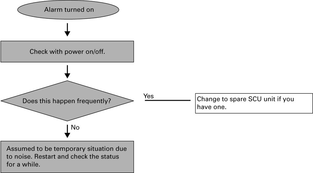
29 Troubleshooting 29
30 3
31 3
 is the contact number of CH2 error indication.")
32 32 The SCU is mounted in slot, and the contact number in ( ) is the contact number of CH2 error indication.
33 4 Product Dimensions and Installation NX7 PLC Product Dimensions System Dimensions (mm) A C B 4 - M5 unit (mm) Slot Types Catalog Number Dimensions (A) Dimensions (B) Dimensions (C) 2-slot type NX7-BASE slot type NX7-BASE slot type NX7-BASE slot type NX7-BASE slot type NX7-BASE slot type NX7-BASE slot type NX7-BASE
34 Power Unit Dimensions(mm) CPU, I/O, Special Unit Dimensions (mm) COM RS232C RS485 COM2 RS232C RS485 34
35 Mounting/Dismounting Module Installation. Insert the module by inserting the tab into the groove first and pushing the module against the backplane. Removal. Unfasten the screw that holds the module in place using a screwdriver. 2. Push the top of the module toward the backplane until it is clamped in place. 2. Hold on pressing the locking button on the top edge of the module, and pull the module from the backplane. Locking button 3. Ensure that the module is in place against the backplane, and then fasten the screw using a screwdriver. screw 35
36 36
37
38 SCU(Serial Communications Unit) OE MAX Controls Trademarks not belonging to OE MAX Controls are property of their respective companies. Copyright 24 OE MAX Controls Publication NX7-UM5A-EN-P-December 24
NX70/NX700 Serial Communications Unit (SCU) User Manual
 User Manual") NX7/NX7 Serial Communications Unit (SCU) User Manual Important User Information Solid state equipment has operational characteristics differing from those of electromechanical equipment. Because of these
NX7/NX7 Serial Communications Unit (SCU) User Manual Important User Information Solid state equipment has operational characteristics differing from those of electromechanical equipment. Because of these
NX70/NX700 Series Analog Modules (A/D, D/A, RTD, TC) User Manual
 User Manual") NX70/NX700 Series Analog Modules (A/D, D/A, RTD, TC) User Manual Important User Information Solid state equipment has operational characteristics differing from those of electromechanical equipment. Because
NX70/NX700 Series Analog Modules (A/D, D/A, RTD, TC) User Manual Important User Information Solid state equipment has operational characteristics differing from those of electromechanical equipment. Because
NX70/NX700 Series High-Speed Counter Modules (4CH) (NX70-HSC4 and NX-HSC4) User Manual
 (NX70-HSC4 and NX-HSC4) User Manual") NX70/NX700 Series High-Speed Counter Modules (4CH) (NX70-HSC4 and NX-HSC4) User Manual Important User Information Solid state equipment has operational characteristics differing from those of electromechanical
NX70/NX700 Series High-Speed Counter Modules (4CH) (NX70-HSC4 and NX-HSC4) User Manual Important User Information Solid state equipment has operational characteristics differing from those of electromechanical
TABLE OF CONTENTS. Communication Functions
 TABLE OF CONTENTS Chapter 1: Chapter 2: Chapter 3: Chapter 4: General Features....................................................... 1-1 Functions......................................................
RS232C/RS485 Data can be easily monitored by LAN
 KS SIGNAL CVERTER (AKS) RSC/RS8 Data can be easily monitored by LAN KS SIGNAL CVERTER FEATURES The connectors are located on the front panel. Easy to connect Easy to operate Can be connected to the LAN
HITACHI. EH-150 series PLC EH-RTD8 Resistance Temperature Detective input module Instruction manual. Safety precautions
 HITACHI EH-150 series PLC Resistance Temperature Detective input module Instruction manual Thank you for purchasing a Hitachi Programmable Logic Controller. To operate it safely, please read this instruction
AD-8923-BCD. Remote Controller (BCD) INSTRUCTION MANUAL 1WMPD
 INSTRUCTION MANUAL 1WMPD") AD-8923-BCD Remote Controller (BCD) INSTRUCTION MANUAL 1WMPD4002137 2010 A&D Company, Limited. All rights reserved. No part of this publication may be reproduced, transmitted, transcribed, or translated
AD-8923-BCD Remote Controller (BCD) INSTRUCTION MANUAL 1WMPD4002137 2010 A&D Company, Limited. All rights reserved. No part of this publication may be reproduced, transmitted, transcribed, or translated
PROGRAMMABLE CONTROLLER. FP0 A/D Converter Unit. Technical Manual ARCT1F321E
 PROGRAMMABLE CONTROLLER Technical Manual ARCT1F321E-2 2008.11 Safety Precautions Observe the following notices to ensure personal safety or to prevent accidents. To ensure that you use this product correctly,
H Series PLC. ! : Indicates Compulsion. EH-150 Analog input module EH-AXH8M Instruction manual. Safety precautions DANGER CAUTION COMPULSION
 H Series PLC EH-150 Analog input module EH-AXH8M Instruction manual Thank you for purchasing a Hitachi Programmable Logic Controller. To operate it safely, please read this instruction manual and all the
Installation Instructions
 Installation Instructions Cat. No. 1771 P3, P4, P5 and P5E Use this document as a guide when installing the catalog number 1771-P3, -P4, -P5 or -P5E power supplies. Because of the variety of uses for the
Instruction Manual LX7/LX7s
 Instruction Manual LX7/LX7s Table of contents Important User Information.............................. 2 Safety Instructions...................................... 3 Overview..............................................
T1K MODBUS Base Controller Specifications
 Base Controller 1 2 In This Chapter.... Base Controller Setting the DIP Switches Setting the Rotary Address Switches Port Pin out and Wiring RJ12 Serial Port Pin out and Wiring 2 2 Base Controller General
Digital ac/dc (24V) Input Module
 Input Module") Installation Instructions Digital ac/dc (24V) Input Module Catalog Number 1771-IND, Series C Topic Page Important User Information 2 Before You Begin 3 Power Requirements 3 Prevent Electrostatic Discharge
Installation Instructions Digital ac/dc (24V) Input Module Catalog Number 1771-IND, Series C Topic Page Important User Information 2 Before You Begin 3 Power Requirements 3 Prevent Electrostatic Discharge
Installation Instructions
 Installation Instructions (Catalog Number 1771-OD) This document provides information on: Because of the variety of uses for the products described in this publication, those responsible for the application
Preface. Copyright 1997, Digital Electronics Corporation MS-DOS and Windows 95 are registered trademarks of the Microsoft Corporation.
 Preface Thank you for purchasing the Profibus DP unit, hereafter referred to as the Profibus unit. This unit is intended for use with the Digital Electronics Corporation s GP-470/570/675/870 series touch
MICRO 3 C PLC User s Manual
 MICRO 3 C PLC User s Manual SAFETY PRECAUTIONS Read this user s manual to make sure of correct operation before starting installation, wiring, operation, maintenance, and inspection of the MICRO 3 C. All
Automationdirect.com
 Automationdirect.com DirectTouch Panel DP-C321 (Color)/ DP-M321 (Monochrome) DP-321 USER MANUAL WARNING Rev. E* Thank you for purchasing automation equipment from Automationdirect.com. We want your new
Appearance Size (mm) Power supply voltage Model (W H D) 100 to 240 VAC K3SC to 240 VAC
 Power supply voltage Model (W H D) 100 to 240 VAC K3SC to 240 VAC") Interface Converter A compact converter that allows communications between RS-C/USB and RS-/8 devices. Ideal for industrial applications. Allows communications between RS-C/USB (Universal Serial Bus) and
Interface Converter A compact converter that allows communications between RS-C/USB and RS-/8 devices. Ideal for industrial applications. Allows communications between RS-C/USB (Universal Serial Bus) and
Package Contents. GP Options (Made by Digital)
") When connecting the power cord terminals to the GP, be sure the cord has first been unplugged from the power outlet to prevent the possibility of an electric shock. With the exception of changing the GP's
When connecting the power cord terminals to the GP, be sure the cord has first been unplugged from the power outlet to prevent the possibility of an electric shock. With the exception of changing the GP's
PLC-CPU-CM3-SP Series
 FEATURES Processor Speed: 200 ns/step 16DI/16DO 10K Steps of Program Memory Expansion Max: 11 Modules (Max 384 pts.) PID Control Two 20K pps High-Speed Counters Built in Two 100K pps Pulse Output Built
Programmable Relay ZEN V2 Units
 Programmable Relay ZEN V2 Units Please read and understand this catalog before purchasing the products. Please consult your OMRON representative if you have any questions or comments. Refer to Warranty
Installation Instructions
 Installation Instructions (Cat. No. 1771-OBN Series B) Use this document as a guide when installing the catalog number 1771-OBN series B output module. Because of the variety of uses for the products described
USER S MANUAL Enhanced Communication Function
 UM-TS02E -E003 PROGRAMMABLE CONTROLLER PROSEC T2E/T2N USER S MANUAL Enhanced Communication Function Main Menu Contents TOSHIBA CORPORATION Important Information Misuse of this equipment can result in property
NIR Moisture Analyzer KB-30
 NIR Moisture Analyzer KB-30 Operation Manual Safety Precautions FPL950701 Improper use of the NIR moisture analyzer in violation of the following safety notes may result in death, injury or damage to property
TOP - 1. Instruction Manual. Version 1.0 Produced in Jan. 2004
 Version 1.0 Produced in Jan. 2004 Instruction Manual LCD monitor IV-08MP Thank you for purchasing the SHARP IV-08MP LCD monitor. Read this introductory instruction manual carefully to thoroughly familiarize
USER'S GUIDE FX-485ADP COMMUNICATION ADAPTER FX0N-485ADP COMMUNICATION ADAPTER
 FX- COMMUNICATION ADAPTER FX0N- COMMUNICATION ADAPTER USER'S GUIDE JY992D53201C This manual contains text, diagrams and explanations which will guide the reader in the correct installation and operation
Phone: Fax: Web:
 Cautions for Your Safety Read the manual carefully before installing, running and maintenance for proper operation. Before using, master the knowledge of the equipment, safety information and all of other
Allen-Bradley Motors
 Installation Instructions Firmware Update Instructions for Ethernet, Enhanced and ControlNet PLC-5 Programmable Controllers Purpose Firmware Update Kit Contents Hardware and Software Requirements This
USB to RS232 Converter USB-013 (Rev3) User s Manual Ver. 1.2 HuMANDATA LTD.
 User s Manual Ver. 1.2 HuMANDATA LTD.") USB to RS232 Converter USB-013 (Rev3) User s Manual Ver. 1.2 HuMANDATA LTD. Table of Contents Precautions... 1 Revision History... 2 Introduction... 2 1. Overview... 3 2. Power Supply... 3 3. Specifications...
USB to RS232 Converter USB-013 (Rev3) User s Manual Ver. 1.2 HuMANDATA LTD. Table of Contents Precautions... 1 Revision History... 2 Introduction... 2 1. Overview... 3 2. Power Supply... 3 3. Specifications...
series USER S MANUAL MICREX-F Personal Computer Loader Adapter <Type:FLT-ASFKA >
 series USER S MANUAL MICREX-F Personal Computer Loader Adapter Safety Precautions Be sure to read the Safety Precautions thoroughly before using the product. Here, the safety precautions
FEATURES FEATURES. Macro Function Usage Supports strong Visual Basic script language which includes more than 500 built-in functions.
 FEATURES Integrated CIMON-SCADA Software Run Powerful Visual Basic Scripts Various Built-In Graphic Libraries Variety of Network Solutions Convenient Report Writing Open-Type Software Using OLE Automation
Analog Output Module. ST-4xxx. User Manual CREVIS Co.,Ltd. Version FnIO S-Series
 1 FnIO S-Series Analog Output Module ST-4xxx User Manual Version 1.01 2012 CREVIS Co.,Ltd 2 FnIO S-Series DOCUMENT CHANGE SUMMARY REV PAGE REMARKS DATE EDITOR 1.0 New Document 2011/10/07 JE KANG 1.01 5
1. Safety Precautions (Read these precautions before use.)
") R P5102S/N/N1 HMI Installation Guide Thank you for purchasing FATEK HMI. Before installing or operating the unit, please read this installation guide carefully to ensure correct use. 1. Safety Precautions
R P5102S/N/N1 HMI Installation Guide Thank you for purchasing FATEK HMI. Before installing or operating the unit, please read this installation guide carefully to ensure correct use. 1. Safety Precautions
Adapter Kit for PanelView 1200/1200e Touch Screen Terminal Cutout
 Installation Instructions Adapter Kit for PanelView 1200/1200e Touch Screen Terminal Cutout Catalog Numbers 2711-NR5T, 2711P-RAT12E2 Topic Page About This Publication 1 Important User Information 2 About
EL1142 Series. IEC / IEEE 1613 Hardened 2-Port 10/100BASE-TX to 2-Port 100BASE-FX Media Converter. User s Guide
 EL1142 Series IEC 61850 / IEEE 1613 Hardened 2-Port 10/100BASE-TX to 2-Port 100BASE-FX Media Converter User s Guide All Rights Reserved Dissemination or reproduction of this document, or its contents,
Kinetix 300 Memory Module Programmer
 Kinetix 300 Memory Module Programmer Catalog Number 2097-PGMR Topic About the Memory Module Programmer 1 Parts List 3 Batteries Operation 4 Using Memory Module Programmer 6 Switch On/Off Memory Module
InView Firmware Update
 Installation Instructions InView Firmware Update Topic Page Hazardous Voltage 3 Change EPROM on 2706-P72, 2706-P74 Display 3 Change EPROM on 2706-P42, 2706-P44 Displays 5 Firmware Upgrade Kit 7 2 InView
MODEL: R2K-1 SEN TRONIC AG. R2K Series
 1 MODEL: R2K-1 R2K Series /RS-485 CONVERTER Functions & Features Bidirectional converter between and RS-485 used when connecting Modbus RS-485 devices to a PC CE marking Standard: Conforms to, EIA Transmission
Installation Instructions
 Installation Instructions (Cat. No. 71-A1B, -A2B, -A3B, -A3B1, -A4B Series B) Because of the variety of uses for the products described in this publication, those responsible for the application and use
IM3523 IM3533 IM IM3536 LCR METER IM3570 IM7580 IM3590 CHEMICAL IMPEDANCE ANALYZER IMPEDANCE ANALYZER. Communication Instruction Manual
 Communication Instruction Manual IM3523 IM3533 IM3533-01 IM3536 LCR METER IM3570 IM7580 IMPEDANCE ANALYZER IM3590 CHEMICAL IMPEDANCE ANALYZER November 2014 Revised edition 6 IM3570A983-06 14-11H i Contents
P3-SCM. General Specifications
 General Specifications Module Type Modules per Base Modules per Group I/O Points Used Field Wiring Connector Operating Temperature Storage Temperature Humidity Environmental Air Vibration Shock Field to
GENERAL PRECAUTIONS GENERAL DESCRIPTION... 6
 Cat.No I173E-EN-01 RX Inverter Expansion I/O Board 3G3AX-EIO21-ROE USER S MANUAL GENERAL PRECAUTIONS... 3 1 GENERAL DESCRIPTION... 6 2 INSTALLATION PROCEDURE... 7 2.1 INSTALLING THE EXPANSION I/O BOARD...
WSK INTELLIGENT TEMPERATURE AND HUMIDITY CONTROLLER USER MANUAL
 WSK INTELLIGENT TEMPERATURE AND HUMIDITY CONTROLLER USER MANUAL WSK INTELLIGENT TEMPERATURE AND HUMIDITY CONTROLLER USER MANUAL v 1.0 Thanks for choosing the Intelligent temperature and humidity controller
Kinetix 6000 Axis Module and Shunt Module
 Installation Instructions Kinetix 6000 and Shunt Module Catalog Numbers 2094-AMxx, 2094-BMxx 2094-AMxx-S, 2094-BMxx-S 2094-BSP2 Topic Page About This Publication 1 Important User Information 2 Before You
PCI Expansion Slot Kit for 6181P (1500P) Series D Integrated Display Computer
 Series D Integrated Display Computer") Installation Instructions PCI Expansion Slot Kit for 6181P (1500P) Series D Integrated Display Computer Catalog Number 6189V-2PCI15R Topic Page About This Publication 1 Important User Information 2 Safety
Installation Instructions PCI Expansion Slot Kit for 6181P (1500P) Series D Integrated Display Computer Catalog Number 6189V-2PCI15R Topic Page About This Publication 1 Important User Information 2 Safety
User Manual Digital Input Module
 EH-RIO2 Series RIO2-XDP4, -XDP8, -XDP16, -XAH4 Version 1.04 Copyright Hitachi Europe GmbH 2015. All rights reserved. DOCUMENT CHANGE SUMMARY REV PAGE REMARKS DATE EDITOR 1.4 All Created 18.06.2015 Winter
PRO-1250D CT MID DIN rail three phase four wire energy meter.
 PRO-1250D CT MID DIN rail three phase four wire energy meter. 1.1 Safety instructions 1.2 Foreword 1.3 MID certificate 1.4 Performance criteria 1.5 Specifications 1.6 Basic errors 1.7 Description 1.8 Dimensions
Allen-Bradley. User Manual. PLC-5 Backup Communication Module (1785-BCM, 1785-BEM) product icon
 product icon") Allen-Bradley PLC-5 Backup Communication Module User Manual (1785-BCM, 1785-BEM) product icon Important User Information Because of the variety of uses for this product and because of the differences between
Allen-Bradley PLC-5 Backup Communication Module User Manual (1785-BCM, 1785-BEM) product icon Important User Information Because of the variety of uses for this product and because of the differences between
Differential Liquid/Gas Pressure Transmitter
 Installation Instruction Differential Liquid/Gas Pressure Transmitter Catalog Number(s) 1414-CPZ10FWFAA, 1414-IPZ10FWFAA Explosion Hazard WARNING Do not use in an explosive or hazardous environment, with
EH-RIO IP67 Profibus-DP I/O modules
 Installation Instructions EH-RIO IP67 Profibus-DP I/O modules (RIO-PBXDP8M12, -PBXDP8M8, -PBYTP8M12, -PBYTP8M8, -PBXYP8M12, -PBXYP8M8) M12 Style Connectors M8 Style Connectors 43819 The EH-RIO IP67 Profibus-DP
i-7550 PROFIBUS to RS-232/422/485 Converter User's Manual High Quality, Industrial Data Acquisition, and Control Products
 i-7550 PROFIBUS to RS-232/422/485 Converter User's Manual High Quality, Industrial Data Acquisition, and Control Products i-7550 PROFIBUS to RS-232/422/485 Converter User's Manual (Version 1.01) PAGE:1
IO-AO6X I/O Expansion Module 6 Isolated Analog Outputs
 IO-AO6X I/O Expansion Module 6 Isolated Analog Outputs The IO-AO6X is an I/O Expansion Module that can be used in conjunction with specific Unitronics OPLC controllers. The module offers 6 12-bit isolated
IO-DI8-TO8, IO-DI8-TO8-L I/O Expansion Modules 8 Inputs, 8 Outputs
 IO-DI8-TO8, IO-DI8-TO8-L I/O Expansion Modules 8 Inputs, 8 Outputs The IO-DI8-TO8 and IO-DI8-TO8-L are I/O expansion modules that can be used in conjunction with specific Unitronics OPLC controllers. The
Teaching Color-Sensing Connected Components Building Block. Quick Start
 Teaching Color-Sensing Connected Components Building Block Quick Start Important User Information Solid state equipment has operational characteristics differing from those of electromechanical equipment.
CJ Series General-purpose Serial Connection Guide OMRON Corporation V500-R2 Series Fixed Laser-Type Barcode Reader
 CJ Series General-purpose Serial Connection Guide OMRON Corporation V500-R2 Series Fixed Laser-Type Barcode Reader P564-E1-01 About Intellectual Property Rights and Trademarks Microsoft product screen
Making Hazardous Operations Safe and Productive
 NEW Safety Guard Switching Unit G9SX-GS Making Hazardous Operations Safe and Productive Making Hazardous Operations Safe and Productive This new addition to the model of Flexible Safety Unit G9SX series
Operation Manual. Fieldbus system EX510-GPR1. PROFIBUS DP Compatible GW unit
 Fieldbus system PROFIBUS DP Compatible GW unit Operation Manual EX50-GPR URL http://www.smcworld.com Akihabara UDX 5F, --, Sotokanda, Chiyoda-ku, Tokyo 0-00, JAPAN Phone: +8 3-507-89 Fax: +8 3-598-536
InView Communication Modules
 Installation Instructions InView Communication Modules Catalog Numbers 2706-PxM, 2706-PxK, 2706-PxP Topic Page About This Publication 1 Important User Information 2 Power Supply Requirements 3 Mount the
G9SX-GS. Safety Guard Switching Unit. A Safety Measure for Hazardous Operations That Does Not Lower Productivity. Auto Switching Function
 Safety Guard Switching Unit CSM DS_E_6_1 A Safety Measure for Hazardous Operations That Does Not Lower Productivity Two functions support two types of application: Auto switching: For applications where
Solid-state Timer H3YN
 Solid-state Timer H3YN Miniature Timer with Multiple Time Ranges and Multiple Operating Modes Minimizes stock. Pin configuration compatible with MY Power Relay. Standard multiple operating modes and multiple
When any of the following symbols appear, read the associated information carefully. Symbol Meaning Description
 Vision OPLC V130 COM Modules: V100-17-CAN, V100-17-RS4/X, V100-17-ET2 This guide shows you how to install an additional communication module in a V130 controller. Instructions and technical specifications
YAMAHA Robot Controller. MRCH/QRCH/QRCX Series UNIT OWNER'S MANUAL
 YAMAHA Robot Controller MRCH/QRCH/QRCX Series UNIT OWNER'S MANUAL Safety Precautions (Always read before starting use) Always read this manual, the robot controller instruction manual and programming manual
Do Not Copy. Important User Information For More Information... 3
 Installation Instructions DH/RS-C Interface Module (Catalog Number 1-KE) Inside page Important User Information... For More Information... Hazardous Location Considerations... Environnements dangereux...
PFXGP4601TAD. Pro-face Xycom GP4000 PFXGP4601TAD
 PFXGP4601TAD http://www.axcontrol.com/automation/pro-face/gp-4000/pfxgp4601tad Pro-face Xycom GP4000 PFXGP4601TAD Pro-face Xycom GP-460xT GP460xT Touch Screen Operator Interface 12.1 TFT Analog Color LCD
THERMO-CON. Model No. HECR002-A5. Keep available whenever necessary.
 HEC-OM-S008 Aug.2014 Communication Manual THERMO-CON Model No. HECR002-A5 Keep available whenever necessary. This manual is copyrighted and all rights are reserved by SMC Corporation, and may not, in whole
FP-e Control Unit New Born! Advanced PLC! Timer, Counter, Hour meter, Temperature Controller and PLC in a Unit
 Control Unit New Born! Advanced PC! Timer, Counter, Hour meter, Temperature Controller and PC in a Unit Features. 5-character, -line, -color Display Simple characters and numerical values can be displayed.
IO-DI8-TO8 I/O Expansion Module 8 Inputs, 8 Outputs
 IO-DI8-TO8 I/O Expansion Module 8 Inputs, 8 Outputs The IO-DI8-TO8 is an I/O expansion module that can be used in conjunction with specific Unitronics OPLC controllers. The module offers 8 digital inputs,
Users Manual STP-103II. Thermal Printer Rev
 Users Manual STP-103II Thermal Printer Rev. 1.00 http://www.bixolon.com Safety Precautions The instructions shown below must be followed to prevent possible danger or damage by using the product incorrectly.
Max. Shock Acc. :147 m/s{15g} Time: 11ms Pulse Wave: Half Since Wave Pulse (3 times in X,Y,Z) IEC IEC Fast Transient Power Module
 IEC IEC Fast Transient Power Module") FEATURES Multi Drop Configuration of up to 32 units Baud Rates Ranging from 300 to 38,400bps 1:1 /1:N / N:M (RS-422) Communication is Supported Supports Full-Duplex (RS-422) and Half-Duplex (RS-485) Built-in
FEATURES Multi Drop Configuration of up to 32 units Baud Rates Ranging from 300 to 38,400bps 1:1 /1:N / N:M (RS-422) Communication is Supported Supports Full-Duplex (RS-422) and Half-Duplex (RS-485) Built-in
PROGRAMMABLE CONTROLLER FP3/FP10S THERMOCOUPLE INPUT UNIT
 PROGRAMMABLE CONTROLLER FP3/FP10S THERMOCOUPLE INPUT UNIT ACG-M0072-1 '96.3 Safety Precautions Observe the following notices to ensure personal safety or to prevent accidents. To ensure that you use this
Communication & Networking
 MicroSmart Master Module Capable of Connecting 62 Slaves Compliance with Ver. 2.1 specifi cations Digital and analog slaves can be connected. Configuration and slave monitoring can be done using LED indicators
Conductive Level Controller
 Conductive Level Controller 61F-D21T-V1 Ideal for level control for industrial facilities and equipment. Outputs can be set to self-hold at ON or OFF using self-holding circuits. Sensitivity adjustment
Solid-state Timer. Ordering Information. Miniature Timer with Multiple Time Ranges and Multiple Operating Modes H3YN- - Accessories (Order Separately)
") Solid-state Timer Miniature Timer with Multiple Time Ranges and Multiple Operating Modes Minimizes stock. Pin configuration compatible with MY Power Relay. Standard multiple operating modes and multiple
Solid-state Timer Miniature Timer with Multiple Time Ranges and Multiple Operating Modes Minimizes stock. Pin configuration compatible with MY Power Relay. Standard multiple operating modes and multiple
F1000 User's Manual. (Version: V1.01)
") (Version: V1.01) Contents Chapter 1 Overview... 2 Chapter 2 Installation... 3 2.1 Installation guide... 3 2.1.1 Installation position... 3 2.1.2 NEMA4 standard installation... 3 2.1.3 Environment precautions...
(Version: V1.01) Contents Chapter 1 Overview... 2 Chapter 2 Installation... 3 2.1 Installation guide... 3 2.1.1 Installation position... 3 2.1.2 NEMA4 standard installation... 3 2.1.3 Environment precautions...
Solar Combiner Enclosure
 Installation Instructions Solar Combiner Enclosure Catalog Numbers 1000-SB006, 1000-SB012 Topic Page Description 1 Important Safety Instructions 3 Nameplate Data 4 Planning for Installation 4 Install the
PFXGP4503TAD. Pro-face Xycom GP4000 PFXGP4503TAD
 PFXGP4503TAD http://www.axcontrol.com/automation/pro-face/gp-4000/pfxgp4503tad Pro-face Xycom GP4000 PFXGP4503TAD Pro-face Xycom GP-450xT GP450xT Touch Screen Operator Interface 10.4 TFT Analog Color LCD
Appendix 3 Using NS-AL002 Converters
 Appendix 3 Using Converters The RS-232C/RS-422A Converter is connected directly to RS-232C port A or B of the, and converts RS-232C communications to RS-422A/RS-485. Any of the Converters listed in Appendix
EX-RC1 Remote I/O Adapter
 EX-RC1 Remote I/O Adapter The EX-RC1 interfaces between Unitronics Vision OPLCs and remote I/O Expansion Modules distributed throughout your system. The adapter is connected to a PLC via CANbus. Each adapter
USER S MANUAL. FX2N-5A Special function block
 USER S MANUAL FX2N-5A Special function block FX2N-5A Special function block Foreword This manual contains text, diagrams and explanations which will guide the reader in the correct installation and operation
Analog Monitor Installation Manual
 Analog Monitor Installation Manual Part Number: 144-23919 Copyright 2011 Magnetek 1. Preface and Safety Magnetek manufactures products used as components in a wide variety of industrial systems and equipment.
Simple Package Measurement Connected Components Building Block. Quick Start
 Simple Package Measurement Connected Components Building Block Quick Start Important User Information Solid state equipment has operational characteristics differing from those of electromechanical equipment.
Analog Input Installation Manual
 Analog Input Installation Manual August 2011 Part Number: 144-23917 Copyright 2011 Magnetek 1. Preface and Safety Magnetek manufactures products used as components in a wide variety of industrial systems
Modbus Digital Remote I/O. ARM Series. Modbus Sensor Connector Type Digital Remote I/O. Features. User Manual For Communication. Ordering Information
 RM Series Modbus Digital Remote I/O Modbus Connector Type Digital Remote I/O Features Modbus RTU standard protocol Connects with sensor connector, e-con: saves wiring work (sensor connector, CNE Series,
PRO1250D CT M-bus MID DIN rail three phase four wire energy meter. User manual Version 1.11
 PRO1250D CT M-bus MID DIN rail three phase four wire energy meter. User manual Version 1.11 1 Safety instructions...3 2 Foreword...4 3 MID certificate...5 4 CE certificates...6 6 Performance criteria...8
Installation Guide V290 (Color) This guide provides basic information for Unitronics LCD color touchscreen models V C30B and V T40B.
 This guide provides basic information for Unitronics LCD color touchscreen models V C30B and V T40B.") Vision OPLC Installation Guide V290 (Color) This guide provides basic information for Unitronics LCD color touchscreen models V290-19-C30B and V290-19-T40B. General Description Vision OPLCs are programmable
Vision OPLC Installation Guide V290 (Color) This guide provides basic information for Unitronics LCD color touchscreen models V290-19-C30B and V290-19-T40B. General Description Vision OPLCs are programmable
Module Type Controller SRV. PLC/Host Communication Instruction Manual IMS01P05-E5 RKC INSTRUMENT INC.
 Module Type Controller SRV PLC/Host Communication Instruction Manual RKC INSTRUMENT INC. IMS01P05-E5 Modbus is a registered trademark of Schneider Electric. The name of each programmable controller (PLC)
MELSEC iq-f FX5 User's Manual (MELSEC Communication Protocol)
") MELSEC iq-f FX5 User's Manual (MELSEC Communication Protocol) SAFETY PRECAUTIONS (Read these precautions before use.) Before using this product, please read this manual and the relevant manuals introduced
MELSEC iq-f FX5 User's Manual (MELSEC Communication Protocol) SAFETY PRECAUTIONS (Read these precautions before use.) Before using this product, please read this manual and the relevant manuals introduced
PRO1 V21.xxx series MID DIN rail single phase two wire energy meter
 PRO1 V21.xxx series MID DIN rail single phase two wire energy meter PRO1D V21.212 Version 1.1 Note: the picture on the frontpage is a meter from the series of this meter, it might not be exactly the same
Instructions. Modbus RTU Card (WSIQ-COM-MB)
") Instructions (WSIQ-COM-MB) Contents 1 Warnings... 2 2 Important User Information... 2 3 Installation... 2 4 Operation... 3 5... 4 6 Specifications... 15 Product Compatibility The is suitable for use with
Instructions (WSIQ-COM-MB) Contents 1 Warnings... 2 2 Important User Information... 2 3 Installation... 2 4 Operation... 3 5... 4 6 Specifications... 15 Product Compatibility The is suitable for use with
RS-485 Products. ICP Electronics Australia Pty Ltd Communication Cards for PC/IPC P 2-1
 2.1 Communication Cards for PC/IPC P 2-1 2.2 Communication Modules for PAC P 2-2 2.3 Converter/Repeater/Hub/Splitter P 2-3 2.4 Termination Resistor/DC Bias Voltage P 2-5 2.5 I/O Modules P 2-6 2.6 I/O Units
DCC-8 DIGITAL TO EIGHT CURRENT LOOP CONVERTER OPERATING MANUAL
 DCC-8 DIGITAL TO EIGHT CURRENT LOOP CONVERTER OPERATING MANUAL 1 TABLE OF CONTENTS 1. MOUNTING INSTRUCTIONS 1.1 Standard DIN Rail mounting 1.2 Screw Mounting 2. FUSE REPLACEMENT 3. ASSEMBLING THE UNIT
PRO1250D CT MID DIN rail three phase four wire energy meter. User manual Version 1.5
 PRO1250D CT MID DIN rail three phase four wire energy meter. User manual Version 1.5 1 Safety instructions...3 2 Foreword...4 3 CE certificates...5 4 MID certificate...7 5 Performance criteria...8 6 Specifications...8
Easy use Easy read. Warning
 Easy use Easy read Warning To prevent electrical shock or equipment damage, unplug the EC210 unit s power cord from the power supply prior to installing or wiring the EC210. After completing any EC210
C200H-LK401/C500-LK009-V1 PC Link
 Cat. No. W135-E1-3 SYSMAC C200H-LK401/C500-LK009-V1 PC Link PC Link System Manual Revised March 2000 Notice: OMRON products are manufactured for use according to proper procedures by a qualified operator
COMMUNICATION CONVERTER FOR PROFIBUS
 INSTRUCTION MANUAL COMMUNICATION CONVERTER FOR PROFIBUS IFP-100 No.IFP11E3 2012.01 Preface Thank you for purchasing our IFP-100, Communication Converter for PROFIBUS. This manual contains instructions
ArmorPoint I/O Field Potential Distributor, Series A
 Installation Instructions ArmorPoint I/O Field Potential Distributor, Series A (Cat. No. 1738-FPD) The field potential distributor (Cat. no. 1738-FPD) lets you change the field power distribution source
Network Instrumentation Module Communications box NX-CB1 Communications adapter NX-CL1/NX-CR1 Terminal adapter NX-TL1/NX-TR1
 No. CP-SS-1865E Network Instrumentation Module Communications box NX-CB1 Communications adapter NX-CL1/NX-CR1 Terminal adapter NX-TL1/NX-TR1 Overview Network Instrumentation Modules make optimal distributed
Ultra-Small/Ultra-Slim PLC
 Ultra-Small/Ultra-Slim PLC Panasonic Electric Works established a new world standard "SLIM" PLC. Starting from 10 I/O to 32 I/O, the CPU is only 25(w) x 90(h) x 70(d)mm. This is about 1/4 the size of the
User Manual. RS485 Option Board for SV-iS5/iH Series. LG Industrial Systems
 User Manual RS485 Option Board for SV-iS5/iH Series Read this manual carefully before using the RS485 OPTION BOARD and follow the instructions exactly. After reading this manual, keep it at handy for future
MODEL: R1M-A1. PC Recorders R1M Series. SPECIFICATIONS OF OPTION: Q COATING (For the detail, refer to M-System's web site.)
") PC Recorders R1M Series PC RECORDER (contact input, 32 points) Functions & Features Industrial recorder on PC 32-point dry contact inputs Easy system expansion via Modbus RTU Recorded data exportable to
PC Recorders R1M Series PC RECORDER (contact input, 32 points) Functions & Features Industrial recorder on PC 32-point dry contact inputs Easy system expansion via Modbus RTU Recorded data exportable to