Programmable Controllers CJ1
|
|
|
- Morris Gallagher
- 6 years ago
- Views:
Transcription
1 Programmable Controllers CJ1

 19 CJ1M-CPU1 -ETN (CJ1M CPU with Ethernet function) CJ1G-CPU P")


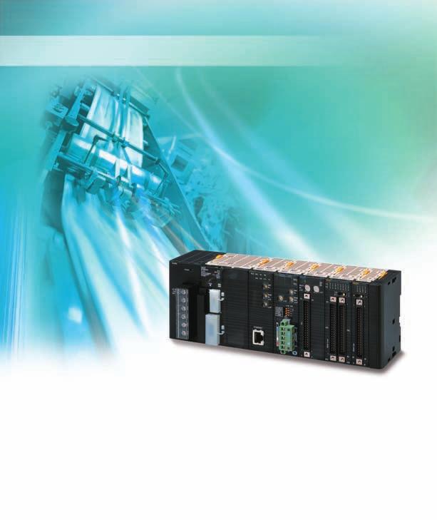
2 The Fast, Small, and Flexible CJ1 Expands the World of Machine Control! Fast! Small! Flexible! Versatile Machine Control with the Highest Performance in the Industry. Super-compact design that meets the highest standards in its class. Even a narrow space in a machine serves as a control panel. Suitable for essentially any application, from small device and temperature control, to large-scale control over networks. Concept 2 System Design Guide 5 System Configuration 6 Dimensions 10 General 13 Common for CPU 15 CJ1M-CPU2 (CJ1M CPU with Built-in I/O) 19 CJ1M-CPU1 -ETN (CJ1M CPU with Ethernet function) CJ1G-CPU P (Loop-control CPU ) Checking Current Consumption and Power Consumption Ordering Information 25 Basic Configuration Programming Devices 31 Optional Products and Maintenance Products 34 DIN Track Accessories 34 Basic I/O 35 Special I/O and CPU Bus 39 Upgraded Basic Functions Height: 90 mm, Depth: 65 mm Application-specific CPU Backplane-free structure for a flexible Rack width. Smaller. CPU are available for a variety of applications, such as CPU with built-in I/O, CPU with Ethernet function, or CPU for loop control. Full Complement of I/O From Basic I/O, Analog, and Position Control to Ethernet, any of the can be used with any of the CPU. New CJ2 series introduction With the base of CJ1 series, CJ2 series with advanced functions has been released. The CJ2 series will easily innovate your systems widely ranging from compact machinery to high-speed and highly precise systems. Refer to the catalog (Cat No. P059) for details. CJ2H (EIP) Cost CJ1M CJ1G-H* CJ1H-R* CJ2M CJ2H Performance and Function * Including models whose production were discontinued. 2 3
3 MEMO 4
4 System Design Guide System Configuration...6 Dimensions...10 General...13 Common for CPU...15 (CJ1M CPU with Built-in I/O)...19 (CJ1M CPU with Ethernet Function)...22 (Loop-control CPU )...22 Checking Current Consumption and Power Consumption
5 PA205R POWER AC V INPUT L2/N OUTPUT RUN DC24V AC240V L1 SYSMAC CJ1G-CPU44 PROGRAMMABLE CONTROLLER OPEN MCPWR BUSY RUN ERR/ALM INH PRPHL COMM PERIPHERAL PORT System Configuration Basic System CJ1 Power Supply CJ1 CPU CJ1 I/O Control Unit CJ1 End Cover CJ1W-PA205C CJ1W-PA205R CJ1W-PA202 CJ1W-PD025 CJ1W-PD022 (-GTC) CJ1W-IC101 CJ1W-TER01 Programming Devices CPU Rack (Backplane-free Structure) CX-One (e.g., CX-Programmer) Programming Console Peripheral Port Cable Personal Computer Cable CS1W-CN226/626 Programmable Terminal (PT) NS Series RS-232C Cable for PT Memory Card HMC-EF183 CJ1 Basic I/O CJ1 Special I/O CJ1 CPU Bus Note: A maximum of 10 can be mounted. Expansion Rack (Backplane-free Structure) CS1 Expansion Cables CS1W-CN@@3 (30 cm, 70 cm, 2 m, 3 m, 5 m, 10 m, 12 m) XW2Z-200T/500T RS-232C Cable for Personal Computer XW2Z-200S/500S-CV CJ1 I/O Interface Unit CJ1W-II101 RS-422A Adapter CJ1W-CIF11 6 Programmable Controllers CJ1
6 Configuration DC Input Unit CJ1W-ID201 AC Input Unit CJ1W-IA201 CJ1 Basic I/O 8-point 16-point 32-point 64-point Input Relay Contact Output Unit (independent commons) CJ1W-OC201 Triac Output Unit CJ1W-OA201 Transistor Output CJ1W-OD201 CJ1W-OD202 CJ1W-OD203 CJ1W-OD204 DC Input Unit CJ1W-ID211 CJ1W-ID212 High-speed type AC Input Unit CJ1W-IA111 Relay Contact Output Unit CJ1W-OC211 Transistor Output CJ1W-OD211 CJ1W-OD213 High-speed type CJ1W-OD212 Interrupt Input Unit CJ1W-INT01 High-speed Input Unit CJ1W-IDP01 DC Input Unit CJ1W-ID231 CJ1W-ID232 CJ1W-ID233 High-speed type Output Transistor Output CJ1W-OD231 CJ1W-OD233 CJ1W-OD234 High-speed type CJ1W-OD232 I/O Other (16 inputs, 16 outputs) DC Input/Transistor Output CJ1W-MD231 CJ1W-MD233 CJ1W-MD232 DC Input Unit CJ1W-ID261 CJ1W-ID262 Transistor Output CJ1W-OD261 CJ1W-OD263 CJ1W-OD inputs, 32 outputs DC Input/Transistor Output CJ1W-MD261 CJ1W-MD inputs, 32 outputs TTL I/O Unit CJ1W-MD563 B7A Interface (64 inputs) CJ1W-B7A14 (64 outputs) CJ1W-B7A04 (32 inputs, 32 outputs) CJ1W-B7A22 Process I/O Isolated-type with Universal Inputs CJ1W-PH41U CJ1W-AD04U Isolated-type Thermocouple Input CJ1W-PTS15 CJ1W-PTS51 Isolated-type Resistance Thermometer Input CJ1W-PTS16 CJ1W-PTS52 Isolated-type DC Input Unit CJ1W-PDC15 Analog I/O Analog Input CJ1W-AD042 High-speed type CJ1W-AD081-V1 CJ1W-AD041-V1 Analog Output CJ1W-DA042V High-speed type CJ1W-DA08V CJ1W-DA08C CJ1W-DA041 CJ1W-DA021 Analog I/O CJ1W-MAD42 Temperature Control CJ1W-TC001, CJ1W-TC002 CJ1W-TC003, CJ1W-TC004 CJ1W-TC101, CJ1W-TC102 CJ1W-TC103, CJ1W-TC104 CJ1 Special I/O and CPU Bus High-speed Counter CJ1W-CT021 Position Control CJ1W-NC214 CJ1W-NC414 CJ1W-NC234 CJ1W-NC434 CJ1W-NC113 CJ1W-NC213 CJ1W-NC413 CJ1W-NC133 CJ1W-NC233 CJ1W-NC433 High-speed type High-speed type High-speed type High-speed type Position Control Unit with EtherCAT interface CJ1W-NC281 CJ1W-NC481 CJ1W-NC881 CJ1W-NCF81 CJ1W-NC482 CJ1W-NC882 Position Control Unit with MECHATROLINK-II interface CJ1W-NC271 CJ1W-NC471 CJ1W-NCF71 CJ1W-NCF71-MA Motion Control Unit with MECHATROLINK-II interface CJ1W-MCH71 Serial Communications CJ1W-SCU22 High-speed type CJ1W-SCU32 High-speed type CJ1W-SCU42 High-speed type CJ1W-SCU21-V1 CJ1W-SCU31-V1 CJ1W-SCU41-V1 EtherNet/IP Unit CJ1W-EIP21 Ethernet Unit CJ1W-ETN21 Controller Link CJ1W-CLK23 FL-net Unit CJ1W-FLN22 DeviceNet Unit CJ1W-DRM21 CompoNet Master Unit CJ1W-CRM21 CompoBus/S Master Unit CJ1W-SRM21 EtherCAT Slave Unit CJ1W-ECT21 ID Sensor CJ1W-V680C11 CJ1W-V680C12 CJ1W-V600C11 CJ1W-V600C12 Note 1.Windows is a registered trademark of Microsoft Corporation in the United States and other countries. Microsoft product screen shots reprinted with permission from Microsoft Corporarion. CompoNet TM, DeviceNet TM and EtherNet/IP TM are trademarks of the ODVA. Other company names and product names in this document are the trademarks or registered trademarks of their respective companies. 2. Including models whose production are discontinued. High-speed Data Storage Unit CJ1W-SPU01-V2 Programmable Controllers CJ1 7
7 PROGRAMMABLE CONTROLLER OPEN MCPWR BUSY RUN ERR/ALM INH PRPHL COMM CJ-series CPU Racks A CJ-series CPU Rack consists of a CPU Unit, Power Supply Unit, Configuration (Basic I/O, Special I/O, and CPU Bus ), and an End Cover. Power Supply Unit CJ1W-P@@@ (@) CPU Unit CJ1@-CPU@@ (@) I/O Control Unit CJ1W-IC101 (Required only when connecting to an Expansion Rack.) End Cover CJ1W-TER01 (One End Cover is provided as a standard accessory with the CPU Unit.) PA205R POWER SYSMAC CJ1G-CPU44 CPU Rack L1 AC V INPUT L2/N PERIPHERAL RUN OUTPUT AC240V DC24V PORT CJ-series Basic I/O CJ-series Special I/O CJ-series CPU Bus Total: 10 max Required CPU Rack Rack Unit name Required number of Power Supply Unit 1 CPU Unit 1 I/O Control Unit Number of Configuration End Cover Required only for mounting to an Expansion Rack. 10 max. (Same for all models of CPU Unit.) (The number of Basic I/O, Special I/O, and CPU Bus can be varied. The number does not include the I/O Control Unit.) 1 (Included with CPU Unit.) Types of In the CJ Series, are classified into the following three types. The number of Racks differs depending on the type. Type Appearance (example) Description Unit recognition method No. of Basic I/O Basic I/O with contact inputs and contact outputs. Recognized by the CPU Unit according to the position of the Rack and slot. No restrictions. Special I/O Special I/O provide more advanced functions than do Basic I/O, including I/O other than contact inputs and contact outputs. Examples of Special I/O are Analog I/O and High-speed Counter. They differ from CPU Bus (including Network Communications ) in having a smaller area for exchanging data with the CPU Unit. Recognized by the CPU Unit according to the unit number (0 to 95) set with the rotary switches on the front panel. A maximum of 96 can be connected. (Multiple unit numbers are per Unit, depending on the model and settings.) CPU Bus CPU Bus exchange data with the CPU Unit via the CPU Bus. Examples of CPU Bus are Network Communications and Serial Communications. They differ from Special I/O in having a larger area for exchanging data with the CPU Unit. Recognized by the CPU Unit according to the unit number (0 to F) set with the rotary switch on the front panel. A maximum of 16 can be mounted. (See note.) Note: CJ1M-CPU1@-ETN: A Maximum of 15 can be mounted. (The built-in Ethernet port on the CPU Unit must be as one of the CPU Bus ) 8 Programmable Controllers CJ1
8 CJ-series Expansion Racks A CJ-series Expansion Rack consists of a Power Supply Unit, an I/O Interface Unit, Configuration (Basic I/O, Special I/O, and CPU Bus ), and an End Cover. Power Supply Unit CJ1W-P@@@(@) CPU Unit CJ1@-CPU@@@(@) I/O Control Unit CJ1W-IC101 CPU Rack I/O Interface Unit CJ1W-II101 Power Supply Unit CJ1W-P@@@(@) Configuration : 10 max. I/O Connecting Cable CS1W-CN@@3 Expansion Rack Total cable length 12 m I/O Interface Unit CJ1W-II101 CJ1W-P@@@(@) Power Supply Unit Configuration : 10 max. I/O Connecting Cable CS1W-CN@@3 Expansion Rack Number of Expansion Racks: None, 1, 2, or 3 (Depends on CPU Unit model.) CJ1W-II101 I/O Interface Unit CJ1W-P@@@(@) Power Supply Unit Configuration : 10 max. I/O Connecting Cable CS1W-CN@@3 Expansion Rack Configuration : 10 max. Required Rack Unit name Required number of CPU Rack Expansion Rack I/O Control Unit One Unit. Required only when an Expansion Rack is used. Mount the I/O Control Unit immediately to the right of the CPU Unit. (See note 1.) Power Supply Unit One Unit I/O Interface Unit One Unit. Mount the I/O Interface Unit immediately to the right of the Power Supply Unit. (See note 2.) Number of Configuration Ten max. (The number of Basic I/O, Special I/O, and CPU Bus can be varied. This number does not include the I/O Interface Unit.) End Cover One (Included with the I/O Interface Unit.) Note 1. Mounting the I/O Control Unit in any other location may cause faulty operation. 2. Mounting the I/O Interface Unit in any other location may cause faulty operation. Maximum Number of Configuration That Can Be Mounted CPU Unit Total No. of on CPU Rack No. of Expansion Racks CJ1G CJ1G-CPU45P (-GTC) per Rack 3 Racks x 10 CJ1G-CPU44P CJ1G-CPU43P per Rack 2 Racks x 10 CJ1G-CPU42P CJ1M CJ1M-CPU13 (-ETN) per Rack (See note.) 1 Rack x 10 CJ1M-CPU23 CJ1M-CPU12 (-ETN) per Rack (See note.) Cannot be connected. CJ1M-CPU11 (-ETN) CJ1M-CPU22 CJ1M-CPU21 Note: Up to nine can be connected to a CJ1M-CPU1@-ETN CPU. The maximum number of Configuration that can be connected is thus reduced by 1. Programmable Controllers CJ1 9
9 SYSMAC CJ1G-CPU44P PROGRAMMABLE CONTROLLER OPEN MCPWR BUSY RUN ERR/ALM INH PRPHL COMM PERIPHERAL PORT LCB03 RDY EXEC INNER LOOP CONTROLLER Dimensions Note: are in mm unless specified otherwise. Product Dimensions W Example Rack Widths using CJ1WPA202 Power Supply Unit (AC, 14 W) No. of mounted with 31- mm width With CJ1M-CPU11/ 12/13 With CJ1M-CPU21/ 22/23 Rack width (mm) With CJ1M-CPU1@- ETN With CJ1G- CPU4@P(-GTC) CPU Unit Power Supply, CPU, and End Covers Unit/product Width CJ1W-PA205C 80 CJ1W-PA205R 80 Power Supply Unit CJ1W-PA CJ1W-PD CJ1W-PD CJ1M-CPU1@ 31 CPU Unit CJ1M-CPU2@ 49 CJ1M-CPU1@-ETN 62 CJ1G-CPU4@P 69 End Cover CJ1W-TER Power Supply 90 W W=27: CJ1W-PD022 W=45: CJ1W-PA202 W=80: CJ1W-PA205R CJ1W-PA205C W=60: CJ1W-PD End Cover (included with CPU ) RS-422A Adapter CJ1W-CIF CPU CJ1G-CPU4@P CJ1M-CPU1@ CJ1M-CPU1@-ETN CJ1M-CPU2@ Programmable Controllers CJ1
10 of Width 20 mm I/O Control Unit I/O Control Unit Unit/product Width 32-point Basic I/O B7A Interface Unit CompoBus/S Master Unit Space Unit 2.7 CJ1W-IC101 CJ1W-ID231/232/233 CJ1W-OD231/232/233/234 CJ1W-B7A22 CJ1W-B7A14 CJ1W-B7A04 CJ1W-SRM21 CJ1W-SP001 (140) Point I/O Fujitsu connector 2.7 (112.5) MIL connector of Width 31 mm Unit Width I/O Interface Unit CJ1W-II101 8/16-point Basic I/O CJ1W-ID201 CJ1W-ID211/212 CJ1W-IA111/201 CJ1W-OD211/212/213 CJ1W-OC201/211 CJ1W-OA point Basic I/O CJ1W-MD231 CJ1W-MD232/ point Basic I/O CJ1W-ID261 CJ1W-OD261 CJ1W-MD261 CJ1W-ID262 CJ1W-OD262/263 CJ1W-MD263 CJ1W-MD Interrupt Input Unit CJ1W-INT01 High-speed Input Unit CJ1W-IDP01 Analog I/O CJ1W-MAD42 Process Input CJ1W-PH41U CJ1W-AD04U CJ1W-PTS51/52/15/16 CJ1W-PDC15 Temperature Control Position Control CJ1W-NC113/133 CJ1W-NC213/233 CJ1W-NC413/433 Unit Width Position Control with EtherCAT interface Position Control Unit with MECHATROLINK-II interface High-speed Counter Unit ID Sensor Controller Link Serial Communications EtherNet/IP Unit Ethernet Unit DeviceNet Unit CompoNet Master Unit FL-net Unit EtherCAT Slave Unit CJ1W-NC281 CJ1W-NC481 CJ1W-NC881 CJ1W-NCF81 CJ1W-NC482 CJ1W-NC882 CJ1W-NC271 CJ1W-NC471 CJ1W-NCF71 CJ1W-NCF71-MA CJ1W-CT021 CJ1W-V680C11 CJ1W-V680C12 CJ1W-V600C11 CJ1W-V600C12 CJ1W-CLK23 CJ1W-SCU22 CJ1W-SCU32 CJ1W-SCU42 CJ1W-SCU41-V1 CJ1W-SCU21-V1 CJ1W-SCU31-V1 CJ1W-EIP21 CJ1W-ETN21 CJ1W-DRM21 CJ1W-CRM21 CJ1W-FLN22 CJ1W-ECT21 31 I/O Interface Unit 2.7 (140) 68 8/6-point Basic I/O, Interrupt Input Unit, and Highspeed Input Unit point Basic I/O and 32-point Basic I/O 2.7 Fujitsu connector MIL connector (112.5) Special I/O and CPU Bus Programmable Controllers CJ1 11
11 Unit of Width 51 mm Unit Width SPU Unit (High-speed Data Storage CJ1W-SPU01-V2 Unit) 51 Position Control CJ1W-NC214/234 (High-speed type) Unit of Width 62 mm Unit Width Position Control (High-speed type) CJ1W-NC414/ Position Contorl Unit (High-speed model) CJ1W-NC414/434 SPU Unit (High-speed Data Storage Unit) CJ1W-SPU01-V Mounting Dimensions Mounting Height A The mounting height of CJ-series CPU Racks and Expansion Racks is from 81.6 to 89.0 mm depending on the that are mounted. Additional height is required to connect Programming Devices (e.g., CX-Programmer or Programming Console) and Cables. Be sure to allow sufficient mounting height. Approx. 100 to 150 mm DIN Track model number PFP-100N2 PFP-100N FPP-50N A 16 mm 7.3 mm 7.3 mm 81.6 to 89.0 mm Note: Consider the following points when expanding the configuration: The total length of I/O Connecting Cable must not exceed 12 m. I/O Connecting Cables require the bending radius indicated below. CJ-series Connecting Cable R R 69 mm Note: Outer diameter of cable: 8.6 mm. 12 Programmable Controllers CJ1
12 General Item Power Supply Unit CJ1W-PA205R CJ1W-PA205C CJ1W-PA202 CJ1W-PD025 CJ1W-PD022 Supply voltage 100 to 240 V AC (wide-range), 50/60 Hz 24 VDC Operating voltage and frequency ranges 85 to 264 V AC, 47 to 63 Hz 19.2 to 28.8 V DC 21.6 to 26.4 V DC Power consumption 100 VA max. 50 VA max. 50 W max. 35 W max. Inrush current (See note 1.) Output capacity (See note 7.) Output terminal (service supply) RUN output (See note 2.) Replacement notification function Insulation resistance Dielectric strength (See note 4.) Noise immunity Vibration Resistance Shock Resistance Ambient operating temperature Ambient operating humidity Atmosphere Ambient storage temperature Grounding Enclosure Weight At 100 to 120 V AC: 15 A/8 ms max. for cold start at room temperature At 200 to 240 V AC: 30 A/8 ms max. for cold start at room temperature 5.0 A, 5 V DC (including supply to CPU Unit) At 100 to 120 V AC: 20 A/8 ms max. for cold start at room temperature At 200 to 240 V AC: 40 A/8 ms max. for cold start at room temperature 2.8 A, 5 V DC (including supply to CPU Unit) At 24 V DC: 30 A/20 ms max. for cold start at room temperature 5.0 A, 5 V DC (including supply to CPU Unit) 2.0 A, 5 V DC (including supply to CPU Unit) 0.8 A, 24 V DC 0.4 A, 24 V DC 0.8 A, 24 V DC 0.4 A, 24 V DC Total: 25 W max. Total: 14 W max. Total: 25 W max. Total: 19.6 W max. Not provided. Contact configuration: SPST-NO Switch capacity: 250 V AC, 2 A (resistive load) Not provided. 120 V AC, 0.5 A (inductive load), 24 V DC, 2A (resistive load) 24 V DC, 2 A (inductive load) With Alarm output (opencollector output) Not provided. 30 V DC max., 50 ma max. 20 MΩ min. (at 500 V DC) between AC external and GR terminals (See note 3.) 2,300 V AC 50/60 Hz for 1 min between AC external and GR terminals (See note 3.) Leakage current: 10 ma max. 20 MΩ min. (at 500 V DC) between all external terminals and GR terminal (See note 3.), and between all alarm output terminals. 20 MΩ 1 min. (at 250 V DC) between all alarm output terminals and GR terminal (See note 3.). 2,300 VAC, 50/60 Hz for 1 minute between all external terminals and GR terminal (See note 3.) and between all alarm output terminals with a leakage current of 10 ma max. 1,000 V AC, 50/60 Hz for 1 minute between all alarm output terminals and GR terminal (See note 3.) with a leakage current of 10 ma max. Not provided. 20 MΩ min. (at 500 V DC) between AC external and GR terminals (See note 3.) 2,300 V AC 50/60 Hz for 1 min between AC external and GR terminals (See not 3.) Leakage current: 10 ma max. 20 MΩ min. (at 500 V DC) between DC external and GR terminals (See note 3.) 1,000 V AC, 50/60 Hz for 1 minute between DC external and GR terminals (See note 3.) Leakage current: 10 ma max. 1,000 V AC, 50/60 Hz for 1 minute between DC external and GR terminals (See note 3.) Leakage current: 10 ma max. 2 kv on power supply line (conforming to IEC ) Conforms to IEC to 8.4 Hz with 3.5-mm amplitude, 8.4 to 150 Hz Acceleration of 9.8 m/s 2 for 100 min in X, Y, and Z directions (10 sweeps of 10 min each = 100 min total) Conforms to IEC m/s 2, 3 times in X, Y, and Z directions (100 m/s 2 for Relay Output ) 0 to 55 C 10% to 90% (with no condensation) 10% to 90% (with no condensation) (See note 5.) 10% to 90% (with no condensation) Must be free from corrosive gases. 20 to 70 C (excluding battery) 20 to 75 C (See note 5.) 20 to 75 C (excluding battery) Less than 100 Ω Mounted in a panel. All models are each 5 kg max. (See note 6.) (See note 6.) Programmable Controllers CJ1 13
13 Item Power Supply Unit CJ1W-PA205R CJ1W-PA205C CJ1W-PA202 CJ1W-PD025 CJ1W-PD022 CPU Rack dimensions Safety measures 90.7 to mm (W H D) (not including cables) Note: W = a + b + 20 n + 31 m a: Power Supply Unit: PA205R and PA205C = 80; PA202 = 45; PD025 = 60; PD022=27 b: CPU Unit: CJ1-H or CJ1 = 62; CJ1M-CPU1@ = 31; CJ1M-CPU1@-ETN = 62; CJ1M-CPU2@ = 49 The total width is given by the following: W = n 20 + m 31, where n is the number of 32-point I/O or I/O Control and m is the number of other. Conforms to culus and EC Directives. Note 1. Disconnect the Power Supply LG terminal from the GR terminal when testing insulation and dielectric strength. Testing the insulation and dielectric strength with the LG terminal and the GR terminals connected will damage internal circuits in the CPU Unit. 2. Supported only when mounted to CPU Rack. 3. The inrush current is given for a cold start at room temperature. The inrush control circuit uses a thermistor element with a low-temperature current control characteristic. If the ambient temperature is high or the PLC is hot-started, the thermistor will not be sufficiently cool, and the inrush currents given in the table may be exceeded by up to twice the given values. When selecting fuses or breakers for external circuits, allow sufficient margin in shut-off performance. 4. Maintain an ambient storage temperature of 25 to 30 C and relative humidity of 25% to 70% when storing the Unit for longer than 3 months to keep the replacement notification function in optimum working condition. 5. Change the applied voltage gradually using the adjuster on the Tester. If the full dielectric strength voltage is applied or turned OFF using the switch on the Tester, the generated impulse voltage may damage the Power Supply Unit. 6. CJ1W-PD022 is not insulated between the primary DC power and secondary DC power. 7. Internal components in the Power Supply Unit will deteriorate or be damaged if the Power Supply Unit is used for an extended period of time exceeding the power supply output capacity or if the outputs are shorted. 14 Programmable Controllers CJ1
14 Common Control method Item I/O control method Programming Languages CPU processing mode Instruction length Ladder instructions Execution time Overhead time Basic instructions Special instructions Unit connection method Mounting method Maximum number of connectable Maximum number of Expansion Racks Number of tasks Interrupt types CIO (Core I/O) Area I/O Area Link Area CPU Bus Unit Area Special I/O Unit Area Serial PLC Link Area (CJ1M CPU only) Stored program Cyclic scan and immediate processing are both possible. Ladder Logic (LD), Sequential Function Charts (SFC), Structured Text (ST), and Mnemonic. CJ1M CPU : Normal Mode or Peripheral Servicing Priority Mode CJ1 CPU : Normal Mode or Peripheral Servicing Priority Mode 1 to 7 steps per instruction Approx. 400 (3-digit function codes) CJ1M CPU (CPU12(-ETN)/13(-ETN)/22/23): CJ1M CPU (CPU11(-ETN)/21): CJ1 CPU : CJ1M CPU (CPU12(-ETN)/13(-ETN)/22/23): CJ1M CPU (CPU11(-ETN)/21): CJ1 CPU : CJ1M CPU (CPU12(-ETN)/13(-ETN)/22/23): CJ1M CPU (CPU11(-ETN)/21): CJ1 CPU : No Backplane: connected directly to each other. DIN Track (screw mounting not possible) 0.10 μs min μs min μs min μs min μs min μs min. 0.5 ms min. 0.7 ms min. 0.5 ms min. CJ1M CPU : Total of 20 in the System, including 10 on CPU Rack and 10 on one Expansion Rack. CJ1M CPU (CPU1@-ETN): Total of 19, including 9 on CPU Rack and 10 on one Expansion Rack. (The built-in Ethernet port on the CPU Unit must be to a slots 0, and is counted as one Unit. CJ1 CPU : 3 max. (An I/O Control Unit is required on the CPU Rack and an I/O Interface Unit is required on each Expansion Rack.) CJ1M CPU (CPU 13(-ETN)/23 only): 1 max. (An I/O Control Unit is required on the CPU Rack and an I/O Interface Unit is required on the Expansion Rack.) CJ1M CPU (CPU11(-ETN)/12(-ETN)/21/22): Expansion is not possible. 288 (cyclic tasks: 32, interrupt tasks: 256) With CJ1M CPU, interrupt tasks can be defined as cyclic tasks called extra cyclic tasks. Including these, up to 288 cyclic tasks can be used. Note 1. Cyclic tasks are executed each cycle and are controlled with TKON(820) and TKOF(821) instructions. 2. The following 4 types of interrupt tasks are supported. Power OFF interrupt tasks: 1 max. Scheduled interrupt tasks: 2 max. I/O interrupt tasks: 32 max. External interrupt tasks: 256 max. Scheduled Interrupts: Interrupts generated at a time scheduled by the CPU built-in timer. (See note. 1) I/O Interrupts: Interrupts from Interrupt Input. Power OFF Interrupts (See note 2.): Interrupts executed when the CPU power is turned OFF. External I/O Interrupts: Interrupts from the Special I/O or CPU Bus. Note 1. CJ1 CPU : Scheduled interrupt time interval is either 1 ms to 9,999 ms or 10 ms to 99,990 ms, in units of 1 ms or 10 ms. CJ1M CPU : In addition to the above, a scheduled interrupt time interval of 0.5 ms to ms, in units of 0.1 ms, is also possible. 2. Not supported when the CJ1W-PD022 Power Supply Unit is mounted. 2,560: CIO to CIO (160 words from CIO 0000 to CIO 0159) The setting of the first word can be changed from the default (CIO 0000) so that CIO 0000 to CIO 0999 can be used. I/O bits are to Basic I/O. 3,200 (200 words): CIO to CIO (words CIO 1000 to CIO 1199) Link bits are used for data links and are to in Controller Link Systems. 6,400 (400 words): CIO to CIO (words CIO 1500 to CIO 1899) CPU Bus Unit bits store the operating status of CPU Bus. (25 words per Unit, 16 max.) 15,360 (960 words): CIO to CIO (words CIO 2000 to CIO 2959) Special I/O Unit bits are to Special I/O. (10 words per Unit, 96 max.) 1,440 (90 words): CIO to CIO (words CIO 3100 to CIO 3189) The CIO Area can be used as work bits if the bits are not used as shown here. Programmable Controllers CJ1 15
15 Item 9,600 (600 words): CIO to CIO (words CIO 3200 to CIO 3799) DeviceNet bits are to Slaves for DeviceNet Unit remote I/O communications when the Master function is used with fixed allocations. Fixed allocation setting 1 Outputs: CIO 3200 to CIO 3263 Inputs: CIO 3300 to CIO 3363 Fixed allocation setting 2 Outputs: CIO 3400 to CIO 3463 Inputs: CIO 3500 to CIO 3563 Fixed allocation setting 3 Outputs: CIO 3600 to CIO 3663 Inputs: CIO 3700 to CIO 3763 CIO (Core I/O) Area DeviceNet Area The following words are to the Master function even when the DeviceNet Unit is used as a Slave. Fixed allocation setting 1 Outputs: CIO 3370 (Slave to Master) Inputs: CIO 3270 (Master to Slave) Fixed allocation setting 2 Outputs: CIO 3570 (Slave to Master) Inputs: CIO 3470 (Master to Slave) Fixed allocation setting 3 Outputs: CIO 3770 (Slave to Master) Inputs: CIO 3670 (Master to Slave) The CIO Area can be used as work bits if the bits are not used as shown here. Internal I/O Area 4,800 (300 words): CIO to CIO (words CIO 1200 to CIO 1499) 37,504 (2,344 words): CIO to CIO (words CIO 3800 CIO 6143) These bits in the CIO Area are used as work bits in programming to control program execution. They cannot be used for external I/O. Work Area Holding Area Auxiliary Area Temporary Area Timer Area Counter Area DM Area Index Registers Task Flag Area Trace Memory File Memory 8,192 bits (512 words): W00000 to W51115 (W000 to W511) Controls the programs only. (I/O from external I/O terminals is not possible.) Note: When using work bits in programming, use the bits in the Work Area first before using bits from other areas. 8,192 bits (512 words): H00000 to H51115 (H000 to H511) Holding bits are used to control the execution of the program, and maintain their ON/OFF status when the PLC is turned OFF or the operating mode is changed. Note: The Function Block Holding Area words are from H512 to H1535. These words can be used only for the function block instance area (internally variable area). Read only: 7,168 bits (448 words): A00000 to A44715 (words A000 to A447) Read/write: 8,192 bits (512 words): A44800 to A95915 (words A448 to A959) Auxiliary bits are specific functions. 16 bits (TR0 to TR15) Temporary bits are used to temporarily store the ON/OFF execution conditions at program branches. 4,096: T0000 to T4095 (used for timers only) 4,096: C0000 to C4095 (used for counters only) 32 Kwords: D00000 to D32767 Used as a general-purpose data area for reading and writing data in word units (16 bits). Words in the DM Area maintain their status when the PLC is turned OFF or the operating mode is changed. Internal Special I/O Unit DM Area: D20000 to D29599 (100 words 96 ) Used to set parameters for Special I/O. CPU Bus Unit DM Area: D30000 to D31599 (100 words 16 ) Used to set parameters for CPU Bus. IR0 to IR15 Store PLC memory addresses for indirect addressing. Index registers can be used independently in each task. One register is 32 bits (2 words). CJ1 CPU : Index registers used independently in each task. 32 (TK0000 to TK0031) Task Flags are read-only flags that are ON when the corresponding cyclic task is executable and OFF when the corresponding task is not executable or in standby status. 4,000 words (trace data: 31 bits, 6 words) Memory Cards: Compact flash memory cards can be used (MS-DOS format). OMRON Memory Cards can be used. 16 Programmable Controllers CJ1
16 Function Item Constant cycle time Cycle time monitoring I/O refreshing Timing of special refreshing for CPU Bus I/O memory holding when changing operating modes Load OFF Timer/Counter PV refresh method Input response time setting Mode setting at power-up Flash memory Memory Card functions Filing Debugging Online editing Program protection Error check Error log Serial communications 1 to 32,000 ms (Unit: 1 ms) Possible (Unit stops operating if the cycle is too long): 10 to 40,000 ms (Unit: 10 ms) Cyclic refreshing, immediate refreshing, refreshing by IORF(097). Note: ORF(097) refreshes I/O bits to Basic I/O and Special I/O. With the CJ1M CPU, the CPU BUS UNIT I/O REFRESH (DLNK(226)) instruction can be used to refresh bits to CPU Bus in the CIO and DM Areas. Data links for Controller Link and SYSMAC LINK, remote I/O for DeviceNet, and other special refreshing for CPU Bus is performed at the following times: CJ1 and CJ1M CPU : I/O refresh period Depends on the ON/OFF status of the IOM Hold Bit in the Auxiliary Area. All outputs on Output can be turned OFF when the CPU Unit is operating in RUN, MONITOR, or PROGRAM mode. CJ1M CPU : BCD or binary (CX-Programmer Ver. 3.0 or higher). CJ1 CPU : BCD only. Time constants can be set for inputs from Basic I/O. The time constant can be increased to reduce the influence of noise and chattering or it can be decreased to detect shorter pulses on the inputs. Possible. Note: By default, the CPU Unit will start in RUN mode if a Programming Console is not connected. The user program and parameter area data (e.g., PLC Setup) are always backed up automatically in flash memory. (automatic backup and restore.) CPU with unit version 3.0 or later only: When downloading projects from CX-Programmer Ver. 5.0 or higher, symbol table files (including CX-Programmer symbol names, I/O comments), comment files (CX-Programmer rung comments, other comments), and program index files (CX-Programmer section names, section comments, or program comments) are stored in comment memory within the flash memory. Automatically reading programs (autoboot) from Possible. the Memory Card when the power is turned ON. Program replacement during PLC operation Possible. User program: Program file format PLC Setup and other parameters: Format in which data is stored in Memory Card Data file format I/O memory: Data file format (binary format), text format, or CSV format Functions for which Memory Card read/write is supported User program instructions, Programming Devices (including CX-Programmer and Programming Consoles), Host Link computers, AR Area control bits, easy backup operation Memory Card data and the EM (Extended Data Memory) Area can be handled as files. Control set/reset, differential monitoring, data tracing (scheduled, each cycle, or when instruction is executed), instruction error tracing, storing location generating error when a program error occurs. User programs can be overwritten in program-block units when the CPU Unit is in MONITOR or PROGRAM mode. This function is not available for block programming areas. With the CX-Programmer, more than one program block can be edited at the same time. Overwrite protection: Set using DIP switch. Copy protection: Password set using CX-Programmer or Programming Consoles. User-defined errors (i.e., user can define fatal errors and non-fatal errors) The FPD(269) instruction can be used to check the execution time and logic of each programming block. Note: FAL and FALS instructions can be used with the CJ1M CPU to simulate errors. Up to 20 errors are stored in the error log. Information includes the error code, error details, and the time the error occurred. Note: A CJ1M CPU Unit can be set so that user-defined FAL errors are not stored in the error log. Built-in peripheral port: Programming Device (including Programming Console) connections, Host Links, NT Links, Serial Gateway (CompoWay/F master) Built-in RS-232C port: Programming Device (excluding Programming Console) connections, Host Links, no-protocol communications, NT Links, Modbus-RTU Slave, Serial Gateway (CompoWay/F master or Modbus master) Serial Communications Unit (sold separately): Protocol macros, Host Links, NT Links Provided on all models. Clock Power OFF detection time Power OFF detection delay time Memory protection Sending commands to a Host Link computer Remote programming and monitoring Accuracy: Ambient temperature Monthly error 55 C 3.5 min to +0.5 min 25 C 1.5 min to +1.5 min 0 C 3 min to +1 min Note: Used to store the time when power is turned ON and when errors occur. AC Power Supply Unit: 10 to 25 ms (not fixed) DC Power Supply Unit PD025: 2 to 5 ms; PD022: 2 to 10 ms 0 to 10 ms (user-defined, default: 0 ms) Note: Not supported when the CJ1W-PD022 Power Supply Unit is mounted. Held Areas: Holding bits, contents of Data Memory and Extended Data Memory, and status of the counter Completion Flags and present values. Note: If the IOM Hold Bit in the Auxiliary Area is turned ON, and the PLC Setup is set to maintain the IOM Hold Bit status when power to the PLC is turned ON, the contents of the CIO Area, the Work Area, part of the Auxiliary Area, timer Completion Flag and PVs, Index Registers, and the Data Registers will be saved for up to 20 days. FINS commands can be sent to a computer connected via the Host Link System by executing Network Communications Instructions from the PLC. Host Link communications can be used for remote programming and remote monitoring through a Controller Link System or Ethernet network. Programmable Controllers CJ1 17
17 Communicating across network levels Storing comments in CPU Unit Program check Control output signals Battery life Item Self-diagnostics Other functions Remote programming and monitoring from Support Software and FINS message communications can be performed across different network levels, even for different types of network. Pre-Ver. 2.0: Three levels Version 2.0 or later: Eight levels for Controller Link and Ethernet networks (See note.), three levels for other networks. Note: To communicate across eight levels, the CX-Integrator or the CX-Net in Programmer version 4.0 or higher must be used to set the routing tables. I/O comments can be stored as symbol table files in the Memory Card, EM file memory, or comment memory (see note). Note: Comment memory is supported for CX-Programmer version 5.0 or higher and CS/CJ-series CPU with unit version 3.0 or later only. Program checks are performed at the beginning of operation for items such as no END instruction and instruction errors. CX-Programmer can also be used to check programs. RUN output: The internal contacts will turn ON (close) while the CPU Unit is operating (CJ1W-PA205R). Battery Set for CJ1 CPU : CPM2A-BAT01 Battery Set for CJ1M CPU : CJ1W-BAT01 CPU errors (watchdog timer), I/O bus errors, memory errors, and battery errors. Storage of number of times power has been interrupted. (Stored in A514.) Functions Added for New Unit Versions Refer to the CJ-series CJ1 CPU Datasheet. Relations between CX-Programmer Versions and Unit Versions of CPU Refer to the CJ-series CJ1 CPU Datasheet. 18 Programmable Controllers CJ1
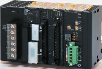
18 (CJ1M CPU with Built-in I/O) CPU have 10 built-in inputs and 6 built-in outputs. The 10 inputs can be used as general-purpose inputs, interrupt inputs, quick-response inputs, high-speed counters, or origin search origin input signals. The 6 outputs can be used as general-purpose outputs, pulse outputs, or origin search deviation counter reset outputs. Data Area Allocations for Built-in I/O I/O Code IN 0 IN 1 IN 2 IN 3 IN 4 IN 5 IN 6 IN 7 IN 8 IN 9 OUT 0 OUT 1 OUT 2 OUT 3 OUT 4 OUT 5 Address Bit Inputs General purpose inputs Interrupt inputs Quick response inputs High-speed counters Outputs General-purpose outputs Pulse outputs Origin search CW/CCW outputs Pulse + direction outputs General purpose input 0 Interrupt input 0 Quick response input 0 Variable duty ratio outputs Origin search 0 (Origin Input Signal) General purpose input 1 Interrupt input 1 Quick response input 1 General purpose input 2 Interrupt input 2 Quick response input 2 Highspeed counter 1 (phase- Z/reset) General purpose input 3 Interrupt input 3 Quick response input 3 Highspeed counter 0 (phase- Z/reset) Note: CJ1M-CPU21 CPU have one PWM output only and do not have PWM output 1. Built-in Input Interrupt Inputs and Quick-response Inputs General purpose input 4 General purpose input 5 General purpose input 6 General purpose input 7 General purpose input 8 General purpose input 9 Highspeed counter 1 (phase- A, increment, or count input) Highspeed counter 1 (phase- B, decrement, or direction input) Highspeed counter 0 (phase- A, increment, or count input) Highspeed counter 0 (phase- B, decrement, or direction input) Generalpurpose output 0 Pulse output 0 (CW) Pulse output 0 pulse) Generalpurpose output 1 Pulse output 0 (CCW) Pulse output 1 (pulse) Generalpurpose output 2 Pulse output 1 (CW) Pulse output 0 (direction) Origin search 0 (Origin Proximity Input Signal) Origin search 1 (Origin Input Signal) Origin search 1 (Origin Proximity Input Signal) Origin search 0 (Positioning Completed Signal) Origin search 1 (Positioning Completed Signal) Generalpurpose output 3 Pulse output 1 (CCW) Pulse output 1 (direction) Generalpurpose output 4 Generalpurpose output 5 PWM(8 91) output 0 Origin search 0 (Error Counter Reset Output) PWM(8 91) output 1 Origin search 1 (Error Counter Reset Output) Item No. of interrupt inputs/ quick-response inputs Input interrupts Direct (Input Interrupt) Mode High-speed Counter Mode Quick-response inputs 4 total Execution of an interrupt task is started at the interrupt input's rising or falling edge. Interrupt numbers 140 to 143 are used (fixed). Response time from meeting input condition to start of interrupt task execution: 93 μs min. Rising or falling edges of the interrupt are counted using either an incrementing or decrementing counter, and an interrupt task is started when the input count reaches the set value. Interrupt numbers 140 to 143 are used (fixed). I/O response frequency: 1 khz Signals that are shorted than the cycle time (30 μs min.) can be read and treated the same as signals that are one for more than one cycle time. High-speed Counter Inputs Item Number of high-speed counters Pulse input mode (Selected in PLC Setup) Response frequency Line-driver inputs 2 (High-speed counters 0 and 1) Differential phase inputs (phase-a, phase-b, and phase- Z input) Up/down inputs (up inputs, down inputs, reset inputs) Pulse + direction inputs (pulse inputs, direction inputs, reset inputs) 50 khz 100 khz 100 khz 100 khz 24-V DC inputs 30 khz 60 khz 60 khz 60 khz Counting mode Linear mode or Ring mode (Select in the PLC Setup.) Increment inputs (increment inputs, reset inputs) Programmable Controllers CJ1 19
19 Count value High-speed counter PV storage locations Control method Item Linear mode: to 7FFFFFFF hex Ring mode: to Ring SV (The Ring SV is set in the PLC Setup and the setting range is to FFFFFFFF hex.) High-speed counter 0: A271 (leftmost 4 digits) and A270 (rightmost 4 digits) High-speed counter 1: A273 (leftmost 4 digits) and A272 (rightmost 4 digits) Target value comparison interrupts or range comparison interrupts can be executed based on these PVs. Note: The PVs are refreshed in the overseeing processes at the beginning of each cycle. Use the PRV(881) instruction to read the most recent PVs. Target value Up to 48 target values and corresponding interrupt task numbers can be registered. comparison Range comparison Up to 8 ranges can be registered, with an upper limit, lower limit, and interrupt task number for each. Phase-Z + Software reset: Counter is reset when phase-z input goes ON while Reset Bit is ON. Software reset: Counter is reset when Reset Bit goes ON. Reset Bits: High-speed Counter 0 Reset Bit is A53100, Counter 1 Reset Bit is A Counter reset method Built-in Output Position Control and Speed Control Item Number of pulse outputs 2 (Pulse output 0 or 1) Output frequency 1 Hz to 100 khz (1-Hz units from 1 to 100 Hz, 10-Hz units from 100 Hz to 4 khz, and 100-Hz units from 4 to 100 khz) Frequency acceleration and deceleration rates Changing SVs during instruction execution Pulse output method Number of output pulses Instruction used for origin searches and returns Instructions used for position and speed control Pulse output PV's storage location Variable-duty Pulse Outputs (PWM) Item Number of PWM outputs Duty ratio Frequency Instruction Set in 1 Hz units for acceleration/deceleration rates from 1 Hz to 2 khz (every 4 ms). The acceleration and deceleration rates can be set separately only with PLS2(887). The target frequency, acceleration/deceleration rate, and target position can be changed. Changes to the target frequency and acceleration/deceleration rate must be made at constant speed. CW/CCW inputs or Pulse + direction inputs Relative coordinates: to 7FFFFFFF hex (Each direction accelerating or decelerating: 2,147,483,647) Absolute coordinates: to 7FFFFFFF hex ( 2,147,483,648 to 2,147,483,647) ORIGIN SEARCH (ORG(889)): Origin search and origin return operations according to set parameters PULSE OUTPUT (PLS2(887)): Trapezoidal output control with separate acceleration and deceleration rate SET PULSES (PULS(886)): Setting the number of pulses for pulse output SPEED OUTPUT (SPED(885)): Pulse output without acceleration or deceleration (Number of pulses must be set in advance with PULS(886) for position control.) ACLERATION CONTROL (ACC(888)): Changes frequency or pulse output with acceleration and deceleration MODE CONTROL (INI(880)): Stopping pulse output The following Auxiliary Area words contain the pulse output PVs: Pulse output 0: A277 (leftmost 4 digits) and A276 (rightmost 4 digits) Pulse output 1: A279 (leftmost 4 digits) and A278 (rightmost 4 digits) The PVs are refreshed during regular I/O refreshing. PVs can be read to user-specified words with the PRV(881) instruction. CJ1M-CPU22/23: 2 (PWM output 0 or 1) CJ1M-CPU21: 1 (PWM output 0) 0% to 100%, set in 0.1% units (See note.) 0.1 Hz to Hz, Set in 0.1 Hz units. PULSE WITH VARIABLE DUTY RATIO (PWM(891)): Sets duty ratio and outputs pulses. Note: CJ1M CPU Unit Ver. 2.0 or later only. (0% to 100%, set in 1% units for Pre-Ver. 2.0 CPU.) 20 Programmable Controllers CJ1
20 Hardware Input Item Number of inputs 10 inputs Input Circuit Configuration Input method 24-V DC inputs or line driver (wiring changed to select) Input voltage specifications 24 V DC Line driver IN0 to IN5 IN6 to IN9 IN0 to IN5 IN6 to IN9 Input voltage 20.4 to 26.4 V DCV RS-422A or RS-422 line driver (conforming to AM26LS31), Power supply voltage of 5 V ± 5% Input impedance 3.6 kω 4.0 kω Input current (typical) 6.2 ma 4.1 ma 13 ma 10 ma Minimum ON voltage 17.4 V DC/3 ma min. Maximum OFF voltage 5.0 V DC/1 ma max. Response speed (for general-purpose inputs) ON response time OFF response time Default setting: 8 ms max. (The input time constant can be set to 0 ms, 0.5 ms, 1 ms, 2 ms, 4 ms, 8 ms, 16 ms, or 32 ms in the PLC Setup.) Default setting: 8 ms max. (The input time constant can be set to 0 ms, 0.5 ms, 1 ms, 2 ms, 4 ms, 8 ms, 16 ms, or 32 ms in the PLC Setup.) Item Input IN0 to IN5 IN6 to IN9 24 V 3.6 kω 24 V 4.0 kω Circuit configuration LD+ 0V/LD 750 Ω 100 Ω 1000 pf 100 Ω Internal circuits LD+ 0V/LD 1.5 kω 100 Ω 1000 pf 100 Ω Internal circuits General-purpose Output for Transistor Outputs (Sinking) Item Output OUT0 to OUT3 OUT4 to OUT5 Rated voltage 5 to 24 V DC Allowable voltage range 4.75 to 26.4 V DC Max. switching capacity 0.3 A/output; 1.8 A/Unit Number of circuits 6 outputs (6 outputs/common) Max. inrush current 3.0 A/output, 10 ms max. Leakage current 0.1 ma max. Residual voltage 0.6 V max. ON delay 0.1 ma max. OFF delay 0.1 ma max. Fuse None External power supply 10.2 to 26.4 V DC 50 ma min. Circuit configuration Internal circuits Low voltage circuit +V OUT0 to OUT3 Internal circuits Low voltage circuit +V OUT4 to OUT5 COM COM Pulse Output (OUT0 to OUT3) Item Max. switching capacity 30 ma, 4.75 to 26.4 V DC Min. switching capacity 7 ma, 4.75 to 26.4 V DC Max. output frequency 100 khz OFF 90% Output waveform ON 10% 2 μs min. 4 μs min. Programmable Controllers CJ1 21
21 (CJ1M CPU with Ethernet Function) These CPU provide built-in Ethernet functionality. Ethernet Functional Element Transfer Media access method Modulation method Transmission paths Baud rate Item Note: The system settings for Ethernet are in the CPU Bus Unit System Setup Area in the CPU Unit. (Loop-control CPU ) In addition to engines for executing sequence control, Loop-control CPU (CJ1G-CPU@@P) have built-in engines for controlling analog quantities (such as temperatures, pressure and flow rate), thus enabling high-speed sequence control and advanced high-speed control of analog quantities in a single Unit. CPU Element (Sequence Control) Note: These Loop-control CPU support gradient temperature control, a technology for uniform in-plane control of temperatures of plane-shaped objects (e.g., multi-point control of surface temperatures based on a multi-point heater). For details, please contact an OMRON representative. Loop Controller Element (Loop Control) CSMA/CD Baseband Star form Specification 100 Mbit/s (100Base-TX), 10 Mbit/s (10Base-T) Transmission media 100 Mbit/s Unshielded twisted-pair (UDP) cable Categories: 5, 5e Shielded twisted-pair (STP) cable Categories: 100 Ω at 5, 5e 10 Mbit/s Unshielded twisted-pair (UDP) cable Categories: 3, 4, 5, 5e Shielded twisted-pair (STP) cable Categories: 100 Ω at 3, 4, 5, 5e Transmission distance 100 m (distance between hub and node) Number of cascade connections There are no restrictions with the use of switching hubs. CPU Bus Unit System Setup Area capacity 994 bytes (See note 2.) Name I/O bits Program capacity DM words EM words CJ1G-CPU45P 32K words 3 banks 60K steps 1,280 bits E0_00000 to E2_32767 CJ1G-CPU45P-GTC (See note.) Loop-control CPU Unit 32K words 30K steps CJ1G-CPU44P 32K words 1 bank 20K steps CJ1G-CPU43P 960 bits E0_00000 to E0_ K steps CJ1G-CPU42P Item CJ1G-CPU42P CJ1G-CPU43P CJ1G-CPU44P CJ1G-CPU45P(-GTC) Operation method Function block method Operation cycle 0.01, 0.02, 0.05, 0.1, 0.2, 0.5, 1, or 2 s (default: 1 s) Can be set for each function block. Number of function blocks Analog operations Sequence control I/O blocks Control and operation blocks Step ladder program blocks Field terminal blocks User link tables Batch allocation System Common block Method for creating and transferring function blocks PID control method Control method Control combinations Alarms PID block internal alarms Alarm blocks 50 blocks max. 300 blocks max. 20 blocks max. 2,000 commands total 200 blocks max. 4,000 commands total 30 blocks max. 40 blocks max. 2,400 data items max. HMI function, 1 EM Area bank Single block Created using CX-Process Tool (order separately) and transferred to Loop Controller. PID with 2 degrees of freedom (with autotuning) Any of the following function blocks can be combined: Basic PID control, cascade control, feed-forward control, sample PI control, Smith dead time compensation control, PID control with differential gap, override control, program control, time-proportional control, etc. 4 PV alarms (upper upper-limit, upper limit, lower limit, lower lower-limit) and 1 deviation alarm per PID block. High/low alarm blocks, deviation alarm blocks 22 Programmable Controllers CJ1

22 Checking Current Consumption and Power Consumption After selecting a Power Supply Unit based on considerations such as the power supply voltage, calculate the current and power requirements for each Rack. Condition 1: Current Requirements There are two voltage groups for internal power consumption: 5 V and 24 V. Current consumption at 5 V (internal logic power supply) Current consumption at 24 V (relay driving power supply) Condition 2: Power Requirements For each Rack, the upper limits are determined for the current and power that can be provided to the mounted. Design the system so that the total current consumption for all the mounted does not exceed the maximum total power or the maximum current supplied for the voltage groups shown in the following tables. The maximum current and total power supplied for CPU Racks and Expansion Racks according to the Power Supply Unit model are shown below. Note 1. For CPU Racks, include the CPU Unit current and power consumption in the calculations. When expanding, also include the current and power consumption of the I/O Control Unit in the calculations. 2. For Expansion Racks, include the I/O Interface Unit current and power consumption in the calculations. Max. current supplied Max. total Power Supply 24 V (relay driving current) plied power sup- 5 V CJ1W-PA205C 5.0 A 0.8 A 25 W CJ1W-PA205R 5.0 A 0.8 A 25 W CJ1W-PA A 0.4 A 14 W CJ1W-PD A 0.8 A 25 W CJ1W-PD A 0.4 A 19.6 W Conditions 1 and 2 below must be satisfied. Condition 1: Maximum Current (1) Total Unit current consumption at 5 V (A) value (2) Total Unit current consumption at 24 V (B) value Condition 2: Maximum Power (1) 5 V + (2) 24 V (C) value Example: Calculating Total Current and Power Consumption Example: When the Following are Mounted to a CJ-series CPU Rack Using a CJ1W-PA202 Power Supply Unit Unit type Quantity Voltage group CPU Unit CJ1M-CPU A I/O Control Unit CJ1W-IC A Basic I/O (Input ) CJ1W-ID A CJ1W-ID A Basic I/O (Output ) CJ1W-OC A A Special I/O Unit CJ1W-DA A CPU Bus Unit CJ1W-CLK A Total Current consumption A 2 Result 1.59 A ( 2.8 A) A ( 0.4 A) Power consumption Total V = 7.95 W A 24 V = W Result = W ( 14 W) Note: For details on Unit current consumption, refer to Ordering Information. Using the CX-Programer to Display Current Consumption and Width CPU Rack and Expansion Rack current consumption and width can be displayed by selecting Current Consumption and Width from the Options Menu in the CS/CJ/CP Table Window. (The width can be displayed for the CJ/CP Series only.) If the capacity of the Power Supply Unit is exceeded, it will be displayed in red characters. For details, refer to the CX-Programmer Operation Manual (Cat. No. W446). Example: Power Supply Unit model Current consumption at 5 V Current consumption at 26 V/24 V Total current consumption Long-distance expansion Width Programmable Controllers CJ1 23
23 MEMO 24
24 Ordering Information Basic Configuration...26 Programming Devices Optional Products and Maintenance Products...34 DIN Track Accessories...34 Basic I/O...35 Special I/O and CPU Bus...39 International The standards are abbreviated as follows: U: UL, U1: UL (Class I Division 2 Products for Hazardous Locations), C: CSA, UC: culus, UC1: culus (Class I Division 2 Products for Hazardous Locations), CU: cul, N: NK, L: Lloyd, : EC Directives, and KC: KC Registration. Contact your OMRON representative for further details and applicable conditions for these standards. Low Voltage Directive Applicable Standard:EN VDC must satisfy the appropriate safety requirements. With PLCs, this applies to Power Supply and I/O that operate in these voltage ranges. These have been designed to conform to EN , which is the applicable standard for PLCs. EC Directives The EC Directives applicable to PLCs include the EMC Directives and the Low Voltage Directive. OMRON complies with these directives as described below. EMC Directives Applicable EMI: EN , EN EMS: EN , EN PLCs are electrical devices that are incorporated in machines and manufacturing installations. OMRON PLCs conform to the related EMC standards so that the devices and machines into which they are built can more easily conform to EMC standards. The actual PLCs have been checked for conformity to EMC standards. Whether these standards are satisfied for the actual system, however, must be checked by the customer. EMC-related performance will vary depending on the configuration, wiring, and other conditions of the equipment or control panel in which the PLC is installed. The customer must, therefore, perform final checks to confirm that the overall machine or device conforms to EMC standards. 25
25 Ordering Information Basic Configuration CPU CJ1 CPU Product name CJ1M CPU Without built-in I/O I/O capacity/ Mountable (Expansion Racks) Program capacity Note 1. Current consumptions include current for a Programming Console. Add 0.15 A per Adapter when using NT-AL001 RS-232C/RS-232A Adapters. Add 0.04 A per Adapter when using CJ1W-CIF11 RS-422A Adapters. 2. The CJ1M low-end models (CJ1M-CPU11(-ETN)/CPU21) have different specifications for the overhead processing time, pulse start time, number of subroutines, number of jumps, number of scheduled interrupts, and number of PWM outputs than the other CJ1M models (CJ1M-CPU12(-ETN)/CPU13(-ETN)/ CPU22/CPU23). For details, refer to the CJ-series Operation Manual (Cat. No. W474) and the CJ-series Built-in I/O Operation Manual (Cat. No. W395). CJ1M CPU (with Built-in I/O) Product name CJ1M CPU Built-in I/O (See note 2.) 640 points/ 20 (1 Expansion Racks max.) 320 points/ 10 (No Expansion Rack) 160 points/ 10 (No Expansion Rack) I/O capacity/ Mountable (Expansion Racks) 640 points/ 20 (1 Expansion Racks max.) 320 points/ 10 (No Expansion Rack) 160 points/ 10 (No Expansion Rack) 20K steps 10K steps 5K steps Program capacity 20K steps 10K steps 5K steps Data memory capacity 32 K words (DM: 32K words, EM: None) Data memory capacity 32K words (DM: 32K words, EM: None) LD instruction execution time 0.1 μs Current consumption (A) LD instruction execution time Note 1. Current consumptions include current for a Programming Console. Add 0.15 A per Adapter when using NT-AL001 RS-232C/RS-232A Adapters. Add 0.04 A per Adapter when using CJ1W-CIF11 RS-422A Adapters. 2. The CJ1M low-end models (CJ1M-CPU11(-ETN)/CPU21) have different specifications for the overhead processing time, pulse start time, number of subroutines, number of jumps, number of scheduled interrupts, and number of PWM outputs than the other CJ1M models (CJ1M-CPU12(-ETN)/CPU13(-ETN)/ CPU22/CPU23). For details, refer to the CJ-series Operation Manual (Cat. No. W474) and the CJ-series Built-in I/O Operation Manual (Cat. No. W395). 3. The connector for built-in I/O in the CJ1M-CPU21/22/23 is not included. Purchase one of the connectors or connector cables, refer to connectors or connector cables on page μs 0.58 (See note 1.) 0.58 (See note 1.) 0.58 (See note 1.) CJ1M-CPU13 CJ1M-CPU12 Current consumption (A) Built-in I/O 10 inputs and 6 outputs, 2 counter inputs, 2 pulse outputs 0.64 (See note 1.) 0.64 (See note 1.) 0.64 (See note 1.) CJ1M-CPU11 (See note 2.) CJ1M-CPU23 (See note 3.) CJ1M-CPU22 (See note 3.) CJ1M-CPU21 (See notes 2 and 3.) UC1, N, L, UC1, N, L, 26 Programmable Controllers CJ1
26 CJ1M CPU (with Ethernet function) Product name CJ1M CPU Ethernet function I/O capacity/ Mountable (Expansion Racks) 640 points/ 20 (1 Expansion Racks max.) 320 points/ 10 (No Expansion Rack) 160 points/ 10 (No Expansion Rack) Program capacity Note 1. Ethernet function The Ethernet functional element provides the main functions of the CJ1W-ETN21 Ethernet Unit. Maximum number of Physical layer Communications service nodes in FINS network Socket services and sending/receiving mail are not supported. 2. Current consumptions include current for a Programming Console. Add 0.15 A per Adapter when using NT-AL001 RS-232C/RS-232A Adapters. Add 0.04 A per Adapter when using CJ1W-CIF11 RS-422A Adapters. 3. The CJ1M low-end models (CJ1M-CPU11(-ETN)/CPU21) have different specifications for the overhead processing time, number of subroutines, number of jumps, and number of scheduled interrupts than the other CJ1M models (CJ1M-CPU12(-ETN)/CPU13(-ETN)/CPU22/CPU23). For details, refer to the CJ-series Operation Manual (Cat. No. W474). CJ1G Loop-control CPU Product name 100BASE-TX, 10BASE-T CJ1G Loopcontrol CPU I/O capacity/ Mountable (Expansion Racks) 1,280 points/ 40 (3 Expansion Racks max.) 960 points/ 30 (2 Expansion Racks max.) 20K steps 10K steps 5K steps 254 Program capacity 60K steps 30K steps 20K steps 10K steps Data memory capacity 32K words (DM: 32K words, EM: None) CPU Unit LD instruction execution time Ethernet function Current consumption (A) Note: Current consumptions include current for a Programming Console. Add 0.15 A per Adapter when using NT-AL001 RS-232C/RS-232A Adapters. Add 0.04 A per Adapter when using CJ1W-CIF11 RS-422A Adapters. 0.1 μs YES (See note 1.) FINS communications service FTP server Automatically adjusted clock information. Web functions Data memory capacity 128K words (DM: 32K words, EM: 32K words 3 banks) 64K words (DM: 32K words, EM: 32K words 1 bank) LD instruction execution time 0.04 μs Loop Controller Number of function blocks: 300 blocks max. Number of function blocks: 50 blocks max (See note 2.) 0.95 (See note 2.) 0.95 (See note 2.) CJ1M-CPU13-ETN CJ1M-CPU12-ETN Current consumption (A) 1.06 (See note.) 1.06 (See note.) 1.06 (See note.) 1.06 (See note.) CJ1M-CPU11-ETN (See notes 3.) CJ1G-CPU45P CJ1G-CPU45P-GTC CJ1G-CPU44P CJ1G-CPU43P CJ1G-CPU42P UC1, N, L, UC1, Programmable Controllers CJ1 27
27 Connector Cables for Built-in I/O in CPU The connector for built-in I/O in the CJ1M-CPU21/22/23 is not included. Purchase one of the connectors or connector cables in the following table separately. Product name MIL Flat Cable Connectors *1 40-pin Pressurewelded Connectors XG4M-4030-T MIL Discrete Wire Connectors *2 40-pin Crimped Connectors XG5N-401 *4 Applicable Connectors Crimp Contacts for XG5N *3 Loose contacts XG5W-0232 Reel contacts XG5W-0232-R Manual Crimping Tool for XG5N XY2B-7007 Phillips screw (M3 screw terminals,40-terminals) XW2R-J40G-T Normal Connection Method for Built-in I/O (When Connector-Terminal Block Conversion Unit is Used) (with Built-in I/O) Built-in I/O Connector Connector-Terminal Block Conversion Slotted screw (M3 European type,40-terminals) XW2R-E40G-T Special Connecting Cable Push-in spring (Clamp 40-terminals) Connector-Terminal Block Conversion Unit XW2R-P40G-T Terminal Block Connecting Cable for Connector- Terminal Block Conversion Cable length: 1 m Cable length: 1.5 m Cable length: 2 m Cable length: 3 m Cable length: 5 m XW2Z-100K XW2Z-150K XW2Z-200K XW2Z-300K XW2Z-500K For 1 axis XW2B-20J6-8A Connection to Servo Driver with Built-in I/O CJ1M-CPU2@ (with Built-in I/O) Built-in I/O Connector Connecting Cables for CJ1M CPU For OMNUC G5/G Series: XW2Z-@@@J-A33 For SMARTSTEP2: XW2Z-@@@J-A33 Servo Relay Unit for 1 axis XW2B-20J6-8A Servo Driver Connecting Cables For OMNUC G5/G Series: XW2Z-@@@J-B31 For SMARTSTEP2: XW2Z-@@@J-B32 Servo Driver OMNUC G5 Series R88D-KT OMNUC G Series R88D-GT SMARTSTEP2: R7D-BP When two axes are used, two Connecting Cables are required at the Servo Driver for each Servo Relay Unit. Servo Relay Connecting Cable for Servo Relay For 2 axes G5/G Series SMARTSTEP2 XW2B-40J6-9A Cable for CJ1M CPU Unit Cable length: 0.5 m XW2Z-050J-A33 Cable length: 1 m XW2Z-100J-A33 Servo Driver Connecting Cables Cable length: 1 m XW2Z-100J-B31 Cable length: 2 m XW2Z-200J-B31 Cable for CJ1M CPU Unit Cable length: 0.5 m XW2Z-050J-A33 Cable length: 1 m XW2Z-100J-A33 Servo Driver Connecting Cables Cable length: 1 m XW2Z-100J-B32 Cable length: 2 m XW2Z-200J-B32 *1. Socket and Strain Relief set *2. Crimp Contacts (XG5W-0232) are sold separately. *3. Applicable wire size is AWG 28 to 24. For applicable conductor construction and more information, visit the OMRON website at *4. Crimp Contacts are also required. Note: Minimum ordering quantity for loose contacts is 100 pieces and for reel contacts is 1 reel (10,000 pieces). 28 Programmable Controllers CJ1
28 Power Supply One Power Supply Unit is required for each Rack. Product name Power supply voltage 5-VDC output capacity Output capacity 24-VDC output capacity Total power consumption 24-VDC service power supply Options RUN output Maintenance forecast monitor No Yes CJ1W-PA205C AC Power Supply Unit 100 to 240 VAC 5 A 0.8 A 25 W Yes No CJ1W-PA205R UC1, N, L, 2.8 A 0.4 A 14 W No No No CJ1W-PA202 DC Power Supply Unit 24 VDC 5A 0.8 A 25 W No No CJ1W-PD025 2 A 0.4 A 19.6 W No No CJ1W-PD022 UC1, Expansion Racks Select the I/O Control Unit, I/O Interface Unit, Expansion Connecting Cable, and CJ-series Power Supply Unit. CJ-series I/O Control Unit (Mounted on CPU Rack when Connecting Expansion Racks) Product name CJ-series I/O Control Unit Mount one I/O Control Unit on the CJ-series CPU Rack when connecting one or more CJ-series Expansion Racks. Connecting Cable: CS1W-CN@@3 Expansion Connecting Cable Connected Unit: CJ1W-II101 I/O Interface Unit Mount to the right of the CPU Unit. Current consumption (A) 0.02 CJ1W-IC101 UC1, N, L, Note: Mounting the I/O Control Unit in any other location may cause faulty operation. CJ-series I/O Interface Unit (Mounted on Expansion Rack) Product Name CJ-series I/O Interface Unit One I/O Interface Unit is required on each Expansion Rack. Connecting Cable: CS1W-CN@@3 Expansion Connecting Cable Mount to the right of the Power Supply Unit. Current consumption (A) 0.13 CJ1W-II101 UC1, N, L, Note: Mounting the I/O Interface Unit in any other location may cause faulty operation. Programmable Controllers CJ1 29
29 I/O Connecting Cables Product name Cable length: 0.3 m CS1W-CN313 Cable length: 0.7 m CS1W-CN713 I/O Connecting Connects an I/O Control Unit on CJ-series CPU Rack to an I/O Cable Cable length: 2 m CS1W-CN223 Interface Unit on a CJ-series Expansion Rack. or Cable length: 3 m CS1W-CN323 N, L, Connects an I/O Interface Unit on CJ-series Expansion Rack to an I/O Interface Unit on another CJ-series Expansion Rack. Cable length: 5 m CS1W-CN523 Cable length: 10 m CS1W-CN133 Cable length: 12 m CS1W-CN133-B2 30 Programmable Controllers CJ1
30 Programming Devices Support Software Product name Number of licenses Media FA Integrated Tool Package CX-One Ver. The CX-One is a comprehensive software package that integrates Support Software for OMRON PLCs and components. CX-One runs on the following OS. Windows XP (Service Pack 3 or higher, 32-bit version) / Windows Vista (32-bit/64-bit version) / Windows 7 (32-bit/64-bit version) / Windows 8 (32-bit/64-bit version) / Windows 8.1 (32-bit/64-bit version) / Windows 10 (32-bit/64-bit version) (Media only) * CXONE-AL00D-V4 1 license CXONE-AL01D-V4 3 licenses CXONE-AL03D-V4 DVD 10 licenses CXONE-AL10D-V4 30 licenses CXONE-AL30D-V4 CX-One Version 4.@ includes CX-Programmer and CX- Simulator. For details, refer to the CX-One catalog (Cat. No. R134). 50 licenses CXONE-AL50D-V4 Note: Site licenses are available for users who will run CX-One on multiple computers. Ask your OMRON sales representative for details. * The CXONE-AL00D-V4 contains only the DVD installation media for users who have purchased the CX-One Version 4.@ and does not include the license number. Enter the license number of the CX-One Version 4.@ when installing. (The license number of the CX-One Version 3.@ or lower cannot be used for installation.) Support Software in CX-One Version 4.@ The following tables lists the Support Software that can be installed from CX-One Support Software in CX-One CX-Programmer CX-Integrator Switch Box Utility CX-Protocol CX-Simulator CX-Position CX-Motion-NCF CX-Motion-MCH CX-Motion CX-Drive CX-Process Tool Faceplate Auto-Builder for NS CX-Designer NV-Designer CX-Configurator FDT CX-Thermo CX-FLnet Network Configurator CX-Server Communications Middleware PLC Tools Outline Application software to create and debug programs for CS/CJ/CP/NSJ-series, C-series, and CVM1/C-series CPU. Data can be created and monitored for high-speed-type Position Control and Position Control with EtherCAT interface. Application software to build and set up FA networks, such as Controller Link, DeviceNet, CompoNet, CompoWay, and Ethernet networks. The Routing Table Component and Data Link Component can be started from here. DeviceNet Configuration functionality is also included. Utility software that helps you to debug PLCs. It helps you to monitor the I/O status and to monitor/change present values within the PLC you specify. Application software to create protocols (communications sequences) between CS/CJ/CP/NSJ-series or C200HX/HG/HE Serial Communications Boards/ and general-purpose external devices. Application software to simulate CS/CJ/CP/NSJ-series CPU Unit operation on the computer to debug PLC programs without a CPU Unit. Application software to create and monitor data for CS/CJ-series Position Control (except for high-speed type). Application software to create and monitor data for CS/CJ-series Position Control with MECHATROLINK-II interface (MC@71). Application software to create data and motion programs and to monitor data for CS/CJ-series Mosion Control with MECHATROLINK-II interface (MCH71). Application software to create data for CS/CJ-series, C200HX/HG/HE, and CVM1/CV-series Motion Control, and to create and monitor motion control programs. Application software to set and control data for Inverters and Servos. Application software to create and debug function block programs for CS/CJ-series Loop Controllers (Loop Control /Boards, Process Control CPU, and Loop Control CPU ). Application software that automatically outputs screen data as project files for Ns-series PTs from tag information in function block programs created with the CX-Process Tool. Application software to create screen data for NS-series PTs. Application software to create screen data for NV-series small PTs. Application software for setting various units by installing its DTM module. Application software to set and control parameters in components such as Temperature Control. Application software for system setting and monitoring of CS/CJ-series Fl-net. Application software to set up tag data links for CJ2 (Built-in EtherNet/IP) CPU and EtherNet/IP. Middleware necessary for CX-One applications to communicate with OMRON components, such as PLCs, Display Devices, and Temperature Control. Middleware necessary to communicate with CP1L CPU with built-in Ethernet port. A group of components used with CX-One applications, such as the CX-Programmer and CX-Integrator. Includes the following: I/O tables, PLC memory, PLC Setup, Data Tracing/Time Chart Monitoring, PLC Error Logs, File Memory, PLC clock, Routing Tables, and Data Link Tables. Note: Approx. 4.0 GB or more available space is required to install the complete CX-One package. Programmable Controllers CJ1 31
31 PA205R POWER L1 AC V INPUT L2/N RUN OUTPUT AC240V DC24V SYSMAC RUN CJ1G-CPU44 ERR/ALM PROGRAMMABLE INH CONTROLLER PRPHL COMM OPEN MCPWR BUSY PERIPHERAL PORT PA205R POWER PA205R POWER L1 AC V INPUT L2/N RUN OUTPUT AC240V DC24V PA205R POWER L1 AC V INPUT L2/N RUN OUTPUT AC240V DC24V L1 AC V INPUT L2/N RUN OUTPUT AC240V DC24V SYSMAC RUN CJ1G-CPU44 ERR/ALM PROGRAMMABLE INH CONTROLLER PRPHL COMM OPEN MCPWR BUSY PERIPHERAL PORT SYSMAC RUN CJ1G-CPU44 ERR/ALM PROGRAMMABLE INH CONTROLLER PRPHL COMM OPEN MCPWR BUSY PERIPHERAL PORT SYSMAC RUN CJ1G-CPU44 ERR/ALM PROGRAMMABLE INH CONTROLLER PRPHL COMM OPEN MCPWR BUSY PERIPHERAL PORT Cables for Connecting to Support Software in the CX-One (e.g., the CX-Programmer) Product Name Applicable computers Connection configuration Cable length Remarks IBM PC/AT or compatible computer + CS1W-CN226/ CPU Unit peripheral port 2 m CS1W-CN226 Programming Device Connecting Cables for Peripheral Port Connects IBM PC/AT or compatible computers, D-Sub 9-pin RS-232C CS1W-CN226/626 IBM PC/AT or Connecting Cables compatible computer for peripheral port (RS-232C, 9-pin) Peripheral port The following connection method can be used when connecting to an IBM PC/AT or compatible computer via RS-232C cable: IBM PC/AT or compatible computer + XW2Z-200S-CV/ V or XW2Z-500S-CV/V + CS1W-CN118 + CPU Unit peripheral port Peripheral port XW2Z-200S-CV/V XW2Z-500S-CV/V RS-232C Cables CS1W-CN118 Used for Peripheral Bus or Host Link. 6 m CS1W-CN m Used for connecting XW2Z-200S- CV/V or XW2Z- 500S-CV/V RS- 232C Cable to the peripheral port. CS1W-CN118 Programming Device Connecting Cables for RS-232C Port Connects IBM PC/AT or compatible computers, D-Sub 9-pin IBM PC/AT or compatible computer + XW2Z-200S-CV/ V or XW2Z-500S-CV/V + RS-232C port of CPU Unit or Serial Communications Board or Unit IBM PC/AT or compatible computer (RS-232C, 9-pin) XW2Z-200S-CV/V (2m) XW2Z-500S-CV/V (5m) RS-232C Cables CPU Unit built-in RS-232C port 2 m 5 m Used for Peripheral Bus or Host Link. Anti-static connectors XW2Z-200S-CV XW2Z-500S-CV 2 m Used for Host XW2Z-200S-V Link only. 5 m Peripheral Bus not supported. XW2Z-500S-V USB-Serial Conversion Cable and PC driver (on a CD-ROM disk) Complies with USB Specification 2.0 IBM PC/AT or compatible computer (USB port) IBM PC/AT or compatible computer + CS1W-CIF31 + CS1W-CN226/626 + CPU Unit peripheral port IBM PC/AT or compatible computer (USB port) CS1W-CIF31 USB-Serial Conversion Cable Serial Connecting Cable e.g., CS1W-CN226/626, Peripheral port XW2Z-200S-CV/500S-CV, or RS-232C port XW2Z-200S-V/500S-V, CQM1-CIF02 IBM PC/AT or compatible computer + CS1W-CIF31 + XW2Z-200S-CV/500S-CV + CS1W-CN118 + CPU Unit peripheral port IBM PC/AT or compatible computer + CS1W-CIF31 + XW2Z-200S-V/500S + CS1W-CN118 + CPU Unit peripheral port IBM PC/AT or compatible computer + CS1W-CIF31 + XW2Z-200S-CV/500S-CV + RS-232C port of CPU Unit or Serial Communications Unit IBM PC/AT or compatible computer + CS1W-CIF31 + XW2Z-200S-V/500S-V + RS-232C port of CPU Unit or Serial Communications Unit Connect USB Serial Conversion Cable to Serial Connecting Cable, and connect to the PLC peripheral port or RS- 232C port. 0.5 m Used for Peripheral Bus or Host Link. Used for Peripheral Bus or Host Link. Used for Host Link only. Peripheral Bus not supported. Used for Peripheral Bus or Host Link. Used for Host Link only. Peripheral Bus not supported. CS1W-CIF31 N 32 Programmable Controllers CJ1
32 <Note> There are two serial communications modes for connecting Support Software in the CX-One (e.g., the CX-Programmer) to the CJ Series. Serial communications Features mode High-speed communications are enabled in the Peripheral Bus Mode, so normally connect with this serial communications mode when using Support Software in the CX-One, such as the CX-Programmer Peripheral Bus Supported for 1:1 connection only. The baud rate at the Support Software is automatically recognized when the connection is made. Host Link (SYSWAY) is generally the protocol for communications with a host computer. Either a 1:1 or 1:N connection can be used. Slower than the peripheral bus. Host Link (SYSWAY) Connections is possible via a modem or optical adapter, long-distance connection is possible using RS-422A/485, and 1:N connections are possible. Programming Consoles Product name Programming Consoles Programming Console Key Sheet Programming Console Connecting Cables Connects to peripheral port on CPU Unit only. (No connection is required at the RS- 232C port.) An English Keyboard Sheet (CS1W-KS001-E) is required. For C200H-PRO27-E. Cable model (Purchased separately.) CS1W-CN224: 2 m CS1W-CN624: 6 m Programming Console Keyboard CS1W-KS001 Connection configuration C200H-PRO27 Programming Console Connects the C200H-PRO27-E Programming Console. (Length: 2 m) Connects the C200H-PRO27-E Programming Console. (Length: 6 m) CS1W-CN224 (2 m) CS1W-CN624 (6 m) Peripheral port C200H-PRO27-E CS1W-KS001-E CS1W-CN224 CS1W-CN624 U, C, N, Programmable Controllers CJ1 33
33 Optional Products and Maintenance Products Product name Memory Cards Flash memory, 128 MB HMC-EF183 Memory Card Adapter (for computer PCMCIA slot) HMC-AP001 Product name Battery Set Battery for CPU Unit maintenance Battery for Unit maintenance Note 1.The battery is included as a standard accessory with the CPU Unit. 2. The battery service life is 5 years at 25 C. (The service life depends on the ambient operating temperature and the power conditions.) 3. Use batteries within two years of manufacture. CPM2A-BAT01 CJ1W-BAT01 End Cover Mounted to the right-hand side of CJ-series CPU Racks or Expansion Racks. One End Cover is provided as a standard accessory with each CPU Unit and I/O Interface Unit. CJ1W-TER01 UC1, N, L, RS-422A Adapter Converts RS-233C to RS-422A/RS-485. (Application example: With a CJ1M CPU Unit, the Adapter is used for Serial PLC Link at the builtin RS-232C port of the CPU Unit.) CJ1W-CIF11 UC1, N, L, Product name Connection configuration Cable length NS-series PT Connecting Cables Cable for connecting between an NS-series PT and the RS-232C port on the CPU Unit or Serial Communications Board 2 m XW2Z-200T NS-series PT XW2Z-200T (2 m) XW2Z-500T (5 m) RS-232C Cable CPU Unit built-in RS-232C port 5 m XW2Z-500T Cable for connecting between an NS-series PT and the peripheral port on the CPU Unit 2 m XW2Z-200T-2 5 m XW2Z-500T-2 DIN Track Accessories Product name DIN Track Length: 0.5 m; Height: 7.3 mm PFP-50N Length: 1 m; Height: 7.3 mm PFP-100N End Plate Length: 1 m; Height: 16 mm There are 2 stoppers provided with CPU and I/O Interface as standard accessories to secure the on the DIN Track. PFP-100N2 PFP-M 34 Programmable Controllers CJ1
34 Basic I/O Input Unit classification Product name I/O points Input voltage and current Commons External connection No. of words Current consumption (A) 8 inputs 12 to 24 VDC, 10 ma Independent contacts Removable terminal block 1 word 0.08 CJ1W-ID201 DC Input 16 inputs 24 VDC, 7 ma 16 points, Removable terminal block 1 word 0.08 CJ1W-ID inputs High-speed type 24 VDC, 7 ma 16 points, Removable terminal block 1 word 0.13 CJ1W-ID inputs 24 VDC, 4.1 ma 16 points, Fujitsu connector 2 words 0.09 CJ1W-ID231 (See note.) CJ1 Basic I/O 32 inputs 24 VDC, 4.1 ma 32 inputs 24 VDC, 4.1 ma High-speed type 16 points, 16 points, MIL connector 2 words 0.09 MIL connector 2 words 0.20 CJ1W-ID232 (See note.) CJ1W-ID233 (See note.) UC1, N, L, 64 inputs 24 VDC, 4.1 ma 16 points, Fujitsu connector 4 words 0.09 CJ1W-ID261 (See note.) 64 inputs 24 VDC, 4.1 ma 16 points, MIL connector 4 words 0.09 CJ1W-ID262 (See note.) AC Input 8 inputs 200 to 24 VAC, 10 ma (200 V, 50 Hz) 8 points, Removable Terminal Block 1 words 0.08 CJ1W-IA inputs 100 to 120 VAC, 7 ma (100 V, 50 Hz) 16 points, Removable Terminal Block 1 words 0.09 CJ1W-IA111 Note: Connectors are not provided with these connector models. Either purchase one of the following 40-pin Connectors, or use an OMRON XW2R Connector-Terminal Block Conversion Unit or a G7@ I/O Relay Terminal. Programmable Controllers CJ1 35
35 Output Unit classification Product name Output type I/O points Maximum switching capacity Commons External connection No. of words Current consumption (A) Relay Contact Output 8 outputs 250 VAC/24 VDC, 2 A Independent contacts Removable terminal block 1 words max. CJ1W-OC outputs 250 VAC/24 VDC, 2 A 16 points, Removable terminal block 1 words max. CJ1W-OC211 Triac Output Unit 8 outputs 250 VAC, 0.6 A 8 points, Removable terminal block 1 words 0.22 CJ1W-OA201 8 outputs 12 to 24 VDC, 2 A 4 points, Removable terminal block 1 words 0.09 CJ1W-OD201 8 outputs 12 to 24 VDC, 0.5 A 8 points, Removable terminal block 1 words 0.10 CJ1W-OD203 CJ1 Basic I/O Transistor Output Sinking 16 outputs 12 to 24 VDC, 0.5 A 16 points, 16 outputs 16 points, 24 VDC, 0.5 A High-speed type 32 outputs 12 to 24 VDC, 0.5 A 16 points, Removable terminal block Removable terminal block Fujitsu connector 1 words 0.10 CJ1W-OD211 1 words 0.15 CJ1W-OD213 2 words 0.14 CJ1W-OD231 (See note.) UC1, N, L, 32 outputs 12 to 24 VDC, 0.5 A 16 points, MIL connector 2 words 0.14 CJ1W-OD233 (See note.) 32 outputs 16 points, 24 VDC, 0.5 A High-speed type MIL connector 2 words 0.22 CJ1W-OD234 (See note.) Sourcing 64 outputs 12 to 24 VDC, 0.3 A 64 outputs 12 to 24 VDC, 0.3 A 8 outputs 8 outputs 16 outputs 32outputs 24 VDC, 2 A Short-circuit protection 24 VDC, 0.5 A Short-circuit protection 24 VDC, 0.5 A Short-circuit protection 24 VDC, 0.5 A Short-circuit protection 64 outputs 12 to 24 VDC, 0.3 A 16 points, 16 points, 4 points, 8 points, 16 points, 16 points, 16 points, Fujitsu connector MIL connector Removable terminal block Removable terminal block Removable terminal block MIL connector MIL connector 4 words words 0.17 CJ1W-OD261 (See note.) CJ1W-OD263 (See note.) 1 words 0.11 CJ1W-OD202 1 words 0.10 CJ1W-OD204 1 words 0.10 CJ1W-OD212 2 words words 0.17 CJ1W-OD232 (See note.) CJ1W-OD262 (See note.) Note: Connectors are not provided with these connector models. Either purchase one of the following 40-pin Connectors, or use an OMRON XW2R Connector-Terminal Block Conversion Unit or a G7@ I/O Relay Terminal. 36 Programmable Controllers CJ1
36 I/O Unit classification Product name Output type I/O points Input voltage, Input current Maximum switching capacity Commons External connection No. of words Current consumption (A) Sinking 16 inputs 24 VDC, 7 ma 16 outputs 250 VAC/24 VDC, 0.5 A 16 points, Fujitsu 16 points, connector 2 words 0.13 CJ1W-MD231 (See note 2.) UC1, N, DC Input/ Transistor Output Sinking 16 inputs 24 VDC, 7 ma 16 outputs 12 to 24 VDC, 0.5 A 16 points, MIL 16 points, connector 2 words 0.13 CJ1W-MD233 (See note 2.) CJ1 Basic I/O Sinking Sinking 32 inputs 24 VDC, 4.1 ma 32 outputs 12 to 24 VDC, 0.3 A 32 inputs 24 VDC, 4.1 ma 32 outputs 12 to 24 VDC, 0.3 A 16 points, Fujitsu 16 points, connector 16 points, 1 common 16 points, MIL connector 4 words words 0.14 CJ1W-MD261 (See note 1.) CJ1W-MD263 (See note 1.) UC1, N, Sourcing 16 inputs 24 VDC, 7 ma 16 outputs 24 VDC, 0.5 A Short-circuit protection 16 points, MIL 16 points, connector 2 words 0.13 CJ1W-MD232 (See note 2.) UC1, N, L, TTL I/O 32 inputs 5 VDC, 35 ma 32 outputs 5 VDC, 35 ma 16 points, 16 points, 1 common MIL connector 4 words 0.19 CJ1W-MD563 (See note 1.) UC1, N, Note 1.Connectors are not provided with these connector models. Either purchase one of the following 40-pin Connectors, or use an OMRON XW2R Connector-Terminal Block Conversion Unit or a G7@ I/O Relay Terminal. 2. Connectors are not provided with these connector models. Either purchase one of the following 20-pin or 24-pin Connectors, or use an OMRON XW2R Connector-Terminal Block Conversion Unit or a G7@ I/O Relay Terminal. Applicable Connectors Fujitsu Connectors for 32-input, 32-output, 64-input, 64-output, 32-input/32-output, and 16-input/16-output Name Connection Part name Applicable Soldered FCN-361J040-AU Connector C FCN-360C040-J2 Connector Cover 40-pin Connectors 24-pin Connectors Crimped FCN-363J040 Socket FCN-363J-AU Contactor FCN-360C040-J2 Connector Cover Pressure FCN-367J040-AU/F welded Soldered FCN-361J024-AU Connector FCN-360C024-J2 Connector Cover Crimped FCN-363J024 Socket FCN-363J-AU Contactor FCN-360C024-J2 Connector Cover Pressure FCN-367J024-AU/F welded Fujitsu Connectors: CJ1W-ID231(32 inputs): 1 per Unit CJ1W-ID261 (64 inputs) 2 per Unit CJ1W-OD231 (32 outputs):1 per Unit CJ1W-OD261 (64 outputs): 2 per Unit CJ1W-MD261 (32 inputs, 32 outputs): 2 per Unit Fujitsu Connectors: CJ1W-MD231 (16 inputs, 16 outputs): 2 per Unit C C C C C Programmable Controllers CJ1 37
37 MIL Connectors for 32-input, 32-output, 64-input, 64-output, 32-input/32-output, and 16-input/16-output Name Connection Part name Applicable 40-pin Connectors 20-pin Connectors Pressure welded FRC5-AO40-3TOS MIL Connectors: CJ1W-ID232 (32 inputs): 1 per Unit CJ1W-OD232/233 (32 outputs):1 per Unit CJ1W-ID262 (64 inputs): 2 per Unit CJ1W-OD262/263 (64 outputs): 2 per Unit CJ1W-MD263/563 (32 inputs, 32 outputs): 2 per Unit Pressure welded FRC5-AO20-3TOS MIL Connectors: CJ1W-MD232/233 (16 inputs, 16 outputs): 2 per Unit XG4M-4030-T XG4M-2030-T Interrupt Input Unit classification CJ1 Basic I/O Product name Interrupt Input Unit I/O points 16 inputs Input voltage current 24 VDC, 7 ma Commons 16 points, Input pulse width conditions ON time: 0.05 ms max. OFF time: 0.5 ms max. Max. mountable per Unit 2 External connection Remov able terminal block No. of words Current consumption (A) 1 word 0.08 CJ1W-INT01 UC1, N, L, Note 1. Can be used only on CPU Racks, and not on Expansion Racks. 2. The locations where the can be mounted depend on the CPU Rack and the CPU Unit model. CJ2H: From the slot next to the CPU Unit until the four slot. CJ1G, CJ1H: From the slot next to the CPU Unit until the fifth slot. CJ1M: From the slot next to the CPU Unit until the third slot. Quick-response Input Unit classification Product name I/O points Input voltage, Input current Commons Input pulse width conditions External connection No. of words Current consumption (A) CJ1 Basic I/O Highspeed Input Unit 16 inputs 24 VDC, 7 ma 16 points, ON time: 0.05 ms max. OFF time: 0.5 ms max. Removable terminal block 1 word 0.08 CJ1W-IDP01 UC1, N, L, Note: There are no restrictions on the mounting position or number of. B7A Interface Unit classification Product name I/O points Send delay time Output status when error occurs External connection No. of words Current consumption (A) CJ1 Basic I/O B7A Interface 64 inputs Hold 0.07 CJ1W-B7A14 Switchable between Removable the following: 64 outputs terminal Standard: 19.2 ms typ. 4 words 0.07 CJ1W-B7A04 block High-speed: 3 ms typ. 32 inputs/ Hold (inputs only) outputs 0.07 CJ1W-B7A22 UC1, 38 Programmable Controllers CJ1
38 Special I/O and CPU Bus Process I/O Isolated-type with Universal Inputs Unit classification CJ1 Special I/O Product name Process Input (Isolatedtype with Universal Inputs) Input points 4 inputs 4 inputs Signal range selection Set separately for each input Set separately for each input Signal range Universal inputs: Pt100 (3-wire), JPt100 (3-wire), Pt1000 (3-wire), Pt100 (4-wire), K, J, T, E, L, U, N, R, S, B, WRe5-26, PL II, 4 to 20 ma, 0 to 20 ma, 1 to 5 V, 0 to 1.25 V, 0 to 5 V, 0 to 10 V, ±100 mv selectable range 1.25 to 1.25 V, 5 to 5 V, 10 to 10 V, ±10 V selectable range, potentiometer Universal inputs: Pt100, JPt100, Pt1000, K, J, T, L, R, S, B, 4 to 20 ma, 0 to 20 ma, 1 to 5 V, 0 to 5 V, 0 to 10 V Conversion speed (resolution) Resolution (conversion speed): 1/256,000 (conversion cycle: 60 ms/ 4 inputs) 1/64,000 (conversion cycle: 10 ms/ 4 inputs) 1/16,000 (conversion cycle: 5 ms/ 4 inputs) Conversion speed: 250 ms/ 4 inputs Accuracy (at ambient temperature of 25 C) Standard accuracy: ±0.05% of F.S. Accuracy: Platinum resistance thermometer input: (±0.3% of PV or ±0.8 C, whichever is larger) ±1 digit max. Thermocouple input: (±0.3% of PV or ±1.5 C, whichever is larger) ±1 digit max. (See note 2.) Voltage or current input: ±0.3% of F.S. ±1 digit max. External connection Removable terminal block No. of unit numbers 1 Current consumption (A) CJ1W- PH41U (See note 1.) CJ1W- AD04U UC1, UC1, L, Note 1. When using the CJ1W-PH41U, do not mount a Relay Output Unit in the same CPU Rack or Expansion Rack. 2. L and 100 C or less for K and T are ±2 C±1 digit max., and 200 C or less for R and S is ±3 C±1 digit max. No accuracy is specified for 400 C or less for B. Isolated-type Thermocouple Input Unit classification CJ1 Special I/O Product name Process Input (Isolatedtype Thermocouple Input ) Input points 2 inputs 4 inputs Signal range selection Set separately for each input Signal range Thermocouple: B, E, J, K, L, N, R, S, T, U, WRe5-26, PLII DC voltage: ±100 mv Thermocouple: R, S, K, J, T, L, B Conversion speed (resolution) Conversion speed: 10 ms/ 2 inputs, Resolution: 1/64,000 Conversion speed: 250 ms/ 4 inputs Accuracy (at ambient temperature of 25 C) Standard accuracy: ±0.05% of F.S. (See note 1.) Accuracy: (±0.3% of PV or ±1 C, whichever is larger) ±1 digit max. (See note 3.) Current consumption (A) No. of unit External numbers connection Removable terminal block Note 1. The accuracy depends on the sensors used and the measurement temperatures. For details, refer to the user s manual. 2. This is for an external power supply, and not for internal current consumption. 3. L and 100 C or less for K and T are ±2 C±1 digit max., and 200 C or less for R and S is ±3 C±1 digit max. No accuracy is specified for 400 C or less for B (See note 2.) 0.25 CJ1W- PTS15 CJ1W- PTS51 UC1, Programmable Controllers CJ1 39
39 Isolated-type Resistance Thermometer Input Unit classification CJ1 Special I/O Product name Process Analog Input (Isolatedtype Resistance Thermometer Input ) Input points 2 inputs 4 inputs Signal range selection Set separately for each input Common inputs Signal range Resistance thermometer: Pt100, JPt100, Pt50, Ni508.4 Resistance thermometer: Pt100, JPt100 Conversion speed (resolution) Conversion speed: 10 ms/ 2 inputs, Resolution: 1/64,000 Conversion speed: 250 ms/ 4 inputs Accuracy (at ambient temperature of 25 C) Accuracy: ±0.05% of F.S. or ±0.1 C, whichever is larger. External connection Removable terminal block No. of unit numbers Current consumption (A) (See note.) CJ1W-PTS16 Accuracy: ±0.3 C of PV or 1 ±0.8 C, whichever is larger, ±1 digit max CJ1W-PTS52 UC1, Note: This is for an external power supply, and not for internal current consumption. Isolated-type DC Input Unit classification Product name Input points Signal range selection Conversion speed (resolution) Accuracy (at ambient temperature of 25 C) External connection No. of unit numbers Current consumption (A) CJ1 Special I/O Isolatedtype DC Input 2 inputs DC voltage: 0 to 1.25 V, 1.25 to 1.25 V, 0 to 5 V, 1 to 5 V, 5 to 5 V, 0 to 10 V, 10 to 10 V, ±10 V selectable range DC current: 0 to 20 ma, 4 to 20 ma Conversion speed: 10 ms/ 2 inputs Resolution: 1/64,000 Standard accuracy: ±0.05% of F.S. Removable terminal block (See note.) CJ1W-PDC15 UC1, Note: This is for an external power supply, and not for internal current consumption. Analog I/O Analog Input Unit type CJ1 Special I/O Product name Analog Input Unit High-speed type Analog Input Input points 4 inputs 8 inputs 4 inputs Signal range selection Set separately for each input Signal range 1 to 5 V (1/10,000), 0 to 10 V (1/20,000), -5 to 5 V (1/20,000), -10 to 10 V (1/40,000), and 4 to 20 ma (1/10,000) 1 to 5 V, 0 to 5 V, 0 to 10 V, -10 to 10 V, 4 to 20 ma Resolution Conversion period 1/4,000 (Settable to 1/8,000) (See note 1.) 20 μs/1 point, 25 μs/2 points, 30 μs/3 points, 35 μs/4 points The Direct conversion is provided. 1 ms/point (250 μs/point can also be set.) (See note 1.) Accuracy (at ambient temperature of 25 C) Voltage: ±0.2% of F.S. Current: ±0.4% of F.S. Voltage: ±0.2% of F.S. Current: ±0.4% of F.S. (See note 2.) External connection Removable terminal block No. of unit numbers 1 Current consumption (A) 0.52 CJ1W-AD042 UC1, 0.42 CJ1W-AD081-V1 CJ1W-AD041-V1 UC1, N, L, Note 1. The resolution and conversion speed cannot be set independently. If the resolution is set to 1/4,000, then the conversion speed will be 1 ms/point. 2. At 23 ±2 C 40 Programmable Controllers CJ1
40 Analog Output Unit type CJ1 Special I/O Product name Analog Output Unit Analog Output Note 1. The resolution and conversion speed cannot be set independently. If the resolution is set to 1/4,000, the conversion speed will be 1 ms/point. 2. This is for an external power supply, and not for internal current consumption. Analog I/O Unit classification CJ1 Special I/O High-speed type Product name Analog I/O Signal Output range points selection 4 outputs 8 outputs 8 outputs 4 outputs 2 outputs No. of points 4 inputs 2 outputs Set separately for each output Set separately for each input Signal range 1 to 5 V (1/10,000), 0 to 10 V (1/20,000), and 10 to 10 V (1/40,000) 1 to 5 V, 0 to 5 V, 0 to 10 V, -10 to 10 V 4 to 20 ma 1 to 5 V, 0 to 5 V, 0 to 10 V, 10 to 10 V, 4 to 20 ma Signal range 1 to 5 V, 0 to 5 V, 0 to 10 V, 10 to 10 V, 4 to 20 ma Resolution Conversion period 1/4,000 (Settable to 1/8,000) (See note 1.) 20 μs/ 1 point, 25 μs/ 2 points, 30 μs/ 3 points, 35 μs/ 4 points The Direct conversion is provided. 1 ms/point (Settable to 250 μs/ point) (See note 1.) 1/4,000 1 ms/point Signal range selection Resolution (See note.) 1/4,000 (Settable to 1/8,000) Conversion period (See note.) 1 ms/point (Settable to 500 μs/point max.) Accuracy (at ambient temperature of 25 C) ±0.3% of F.S. ±0.3% of F.S. Voltage: ±0.3% of F.S. Current: ±0.5% of F.S. Accuracy (at ambient temperature of 25 C) Voltage input: ±0.2% of F.S. Current input: ±0.2% of F.S. Voltage output: ±0.3% of F.S. Current output: ±0.3% of F.S. External External power connection supply Removable terminal block External connection Removable terminal block No. of unit numbers Current consumption (A) Note: The resolution and conversion speed cannot be set independently. If the resolution is set to 1/4,000, then the conversion speed will be 1 ms/point. 24 VDC +10% 15%, 140 ma max. 24 VDC +10% 15%, 170 ma max. 24 VDC +10% 15%, 200 ma max. 24 VDC +10% 15%, 140 ma max. No. of unit numbers CJ1W-DA042V UC1, (See note 2.) 0.17 (See note 2.) 0.2 (See note 2.) 0.14 (See note 2.) CJ1W-DA08V CJ1W-DA08C CJ1W-DA041 CJ1W-DA021 UC1, N, L, UC1, N, UC1, N, L, Current consumption (A) CJ1W-MAD42 UC1, N, L, Programmable Controllers CJ1 41
41 Temperature Control Unit classification Product name No. of loops Temperature sensor inputs No. of unit numbers Current consumption (A) Control outputs 4 loops Open collector NPN outputs (pulses) 0.25 CJ1W-TC001 4 loops Open collector PNP outputs (pulses) 0.25 CJ1W-TC002 CJ1 Special I/O Temperature Control 2 loops, heater burnout detection function 2 loops, heater burnout detection function 4 loops Thermocouple input (R, S, K, J, T, B, L) Open collector NPN outputs (pulses) Open collector PNP outputs (pulses) Open collector NPN outputs (pulses) CJ1W-TC CJ1W-TC CJ1W-TC101 UC1, N, L, 4 loops 2 loops, heater burnout detection function 2 loops, heater burnout detection function Platinum resistance thermometer input (JPt100, Pt100) Open collector PNP outputs (pulses) Open collector NPN outputs (pulses) Open collector PNP outputs (pulses) 0.25 CJ1W-TC CJ1W-TC CJ1W-TC104 High-speed Counter Unit Unit classification Product name Countable channels Encoder A and B inputs, pulse input Z signals Max. counting rate No. of unit numbers Current consumption (A) CJ1 Special I/O High-speed Counter Unit 2 Input voltage: 5 VDC, 12 V, or 24 V (5 V and 12 V are each for one axis only.) RS-422 line driver 50 khz 500 khz CJ1W-CT021 UC1, N, L, 42 Programmable Controllers CJ1
42 Position Control Position Control (High-speed type) Unit classification CJ1 Special I/O Product name Position Control High-speed type Position Control Unit Cables Control output interface Pulse-train open-collector output with Pulse Counter Function Pulse-train line-driver output with Pulse Counter Function Open-collector output Line-driver output For CJ1W- NC214/ NC414 For CJ1W-NC234/ NC434 Connecting Servo Drives: G Series R88D-GT G5 Series R88D-KT Connecting Servo Drives: SMARTSTEP2 R7D-BP Connecting Servo Drives: G Series R88D-GT G5 Series R88D-KT Connecting Servo Drives: SMARTSTEP2 R7D-BP Connecting Servo Drives: G Series R88D-GT G5 Series R88D-KT Connecting Servo Drives: SMARTSTEP2 R7D-BP Connecting Servo Drives: G Series R88D-GT G5 Series R88D-KT Connecting Servo Drives: SMARTSTEP2 R7D-BP Connecting Servo Drives: G Series R88D-GT G5 Series R88D-KT Connecting Servo Drives: SMARTSTEP2 R7D-BP Applicable Servo Drive: G Series R88D-GT G5 Series R88D-KT Applicable Servo Drive: SMARTSTEP2 R7D-BP No. of axes 2 axes No. of unit numbers Current consumption (A) 0.27 CJ1W-NC axes 0.31 CJ1W-NC414 2 axes 0.27 CJ1W-NC axes 0.31 CJ1W-NC434 1 axis 2 axes 1 axis 2 axes Cable length: 1 m Cable length: 3 m Cable length: 1 m Cable length: 3 m Cable length: 1 m Cable length: 3 m Cable length: 1 m Cable length: 3 m Cable length: 1 m Cable length: 5 m Cable length: 10 m Cable length: 1 m Cable length: 5 m Cable length: 10 m Cable length: 1 m Cable length: 5 m Cable length: 10 m Cable length: 1 m Cable length: 5 m Cable length: 10 m XW2Z-100J-G13 XW2Z-300J-G13 XW2Z-100J-G14 XW2Z-300J-G14 XW2Z-100J-G5 XW2Z-300J-G5 XW2Z-100J-G6 XW2Z-300J-G6 XW2Z-100J-G9 XW2Z-500J-G9 XW2Z-10MJ-G9 XW2Z-100J-G12 XW2Z-500J-G12 XW2Z-10MJ-G12 XW2Z-100J-G1 XW2Z-500J-G1 XW2Z-10MJ-G1 XW2Z-100J-G4 XW2Z-500J-G4 XW2Z-10MJ-G4 UC1, Programmable Controllers CJ1 43
43 Position Control Unit classification Product name Control output interface No. of axes 1 axis No. of unit numbers Current consumption (A) Pulse train, open collector output Position Control 0.25 CJ1W-NC113 1 Pulse train, open collector output 2 axes 0.25 CJ1W-NC213 Pulse train, open collector output (See note.) 4 axes CJ1W-NC413 UC1, Pulse train, line driver output 1 axis 0.25 CJ1W-NC133 1 Pulse train, line driver output 2 axes 0.25 CJ1W-NC233 Pulse train, line driver output (See note.) 4 axes CJ1W-NC433 Space Unit Use a CJ1W-SP001 Space Unit if the operating temperature is 0 to 55 C. CJ1W-SP001 UC1, For 1-Axis Position Control Unit (without communications support) (CJ1W-CN113/133) XW2B-20J6-1B Servo Relay For 2- or 4-Axes Position Control Unit (without communications support) (CJ1W-NC213/233/413/433) XW2B-40J6-2B For 2- or 4-Axes Position Control Unit (with communications support) (CJ1W-NC213/233/413/433) XW2B-40J6-4A CJ1 Special I/O Position Control Unit Cables Open-collector output Line-driver output For CJ1W-NC113 For CJ1W- NC213/413 For CJ1W-NC133 For CJ1W- NC233/433 Connecting Servo Drives: G5/G Series, SMARTSTEP2 Connecting Servo Drives: G5/G Series, SMARTSTEP2 Connecting Servo Drives: G5/G Series, SMARTSTEP2 Connecting Servo Drives: G5/G Series, SMARTSTEP2 1 axis 2 axes 1 axis 2 axes Cable length: 0.5 m Cable length: 1 m Cable length: 0.5 m Cable length: 1 m Cable length: 0.5 m Cable length: 1 m Cable length: 0.5 m Cable length: 1 m XW2Z-050J-A14 XW2Z-100J-A14 XW2Z-050J-A15 XW2Z-100J-A15 XW2Z-050J-A18 XW2Z-100J-A18 XW2Z-050J-A19 XW2Z-100J-A19 Note: The ambient operating temperature for 4-Axes Position Control is 0 to 50 C; the allowable voltage fluctuation on the external 24-VDC power supply is 22.8 to 25.2 VDC (24 V ±5%). 44 Programmable Controllers CJ1

 CJ1W-NC281 4 axes CJ1W-NC481 1 0.46 8 axes CJ1W-NC881 16 axes CJ1W-NCF81 4 axes CS1W-NC482 1 0.")
 CJ1 CPU Bus Unit EtherCAT Slave Unit STP (shielded twisted-pair) cable of category 5 or higher with double shielding Refreshing methods: Free-Run Mode PDO data")
44 Position Control Unit with EtherCAT interface Unit classification CJ1 CPU Bus Product name Position Control Unit with EtherCAT interface EtherCAT Slave Unit Control output interface Control commands executed by EtherCAT communications. Positioning functions: Memory operation, Direct operation by ladder programming Control commands executed by EtherCAT communications. Positioning functions: Memory operation, Direct operation by ladder programming I/O communications: 64 nodes No. of axes 2 axes No. of unit numbers Current consumption (A) CJ1W-NC281 4 axes CJ1W-NC axes CJ1W-NC axes CJ1W-NCF81 4 axes CS1W-NC axes CS1W-NC882 UC1, Unit type Product name Communications cable Communications functions No. of unit numbers Current consumption (A) CJ1 CPU Bus Unit EtherCAT Slave Unit STP (shielded twisted-pair) cable of category 5 or higher with double shielding Refreshing methods: Free-Run Mode PDO data sizes: TxPDO 400byte max./ RxPDO: 400byte max CJ1W-ECT21 UC1,,KC Recommended EtherCAT Communications Cables Category 5 or higher (100BASE-TX) straight cable with double shielding (aluminum tape and braided shielding) is recommended. Cabel with Connectors Wire Gauge and Number of Pairs: AWG 22, 2-pair Cable As of October 2010 Item Cable with Connectors on Both Ends (RJ45/RJ45) Cable with Connectors on Both Ends (M12/RJ45) Appearance Recommended manufacturer OMRON Note: The cable length 0.3, 0.5, 1, 2, 3, 5, 10 and 15m are available. For details, refer to Cat.No.G019. Cable length (m) Cabel with Connectors Wire Gauge and Number of Pairs: AWG 24, 4-pair Cable As of June 2010 Wire Gauge and Number of Pairs: AWG 22, 2-pair Cable As of June XS5W-T421-AMD-K 0.5 XS5W-T421-BMD-K 1 XS5W-T421-CMD-K 2 XS5W-T421-DMD-K 5 XS5W-T421-GMD-K 10 XS5W-T421-JMD-K 0.3 XS5W-T421-AMC-K 0.5 XS5W-T421-BMC-K 1 XS5W-T421-CMC-K 2 XS5W-T421-DMC-K 5 XS5W-T421-GMC-K 10 XS5W-T421-JMC-K Item Appearance Recommended manufacturer Tonichi Kyosan Cable, Ltd. NETSTAR-C5E SAB 0.5 4P Cable Kuramo Electric Co. KETH-SB SWCC Showa Cable Systems Co. FAE-5004 Connector Panduit Corporation MPS588 Item Appearance Recommended manufacturer Cable Kuramo Electric Co. KETH-PSB-OMR * RJ45 Assembly Connector OMRON XS6G-T421-1 * * We recommend you to use above cable and connector together. Programmable Controllers CJ1 45
Power and Expansion Selection
 CJ1 SYSTEM POWER AND EXPANSION Power and Expansion Selection This section provides tools to calculate the CJ1 system current total needed to select the power supply. When the number of modules or power
Note: Do not use this document to operate the Unit. OMRON Corporation. CJ1M-CPU22/23 Models with built-in I/O
 CJ1M-CPU22/23 Models with built-in I/O Connecting Cable for Unit XW2Z-100J-A26 (1 m) Connecting Cable for SMARTSTEP A Series XW2Z-100J-B5 (1 m) XW2Z-200J-B5 (2 m) Servo Relay Unit XW2B-20J6-8A (for one
Programmable Controllers CJ1
 Programmable Controllers CJ1 Expands Concept 2 System Design Guide 17 Flexible! Suitable for essentially any application, from small device and temperature control, to large-scale control over networks.
CPU Units with 20 I/O points
 CPM2A General s CPU Units with 20 I/O points CPU Units with 30 I/O points CPU Units with 40 I/O points Supply voltage AC power 100 to 240 VAC, 50/60 Hz DC power 24 VDC Operating voltage AC power 85 to
Packed with ideal functions for machine control.
 Packed with ideal functions for machine control. Fast! Small! Seamless! The CJ1 Series has expanded to meet the requirements of compact and generalpurpose devices and to support the downsizing of machinery
CS1D Duplex System. Select from a Wide Range of Redundant Systems Easily Achieve Highly Reliable Systems
 Programmable Controllers CS1D Duplex System Redundant CPU Units, Power Supply Units, Communications Units, and Expansion I/O Cables Select from a Wide Range of Redundant Systems Easily Achieve Highly Reliable
Programmable Controller CS1D Duplex System
 Programmable Controller CS1D Duplex System Easily create redundant systems Improve development productivity with FB, ST, and SFC 2 CS1D Duplex System 3 CS1D brings greater development productivity and
Max. I/O units. consumption
 CJ2-Series CPU Units Modular PLC H236 Fast and Powerful CPUs for Any Task All CPU s support IEC61131-3 Structured text, Sequential Function Charts and ladder library helps to reduce your programming effort,
onlinecomponents.com
 CPU Backplane A consists of a CPU, Power Supply Unit, CPU Backplane, Basic I/O Modules, Special I/O Modules, and CPU Bus Modules. The Serial Communications Board and Memory Cards are optional. The Backplane
Despite its ultra-slim design, a CPM2C system can provide up to 192 I/O points!
 Despite its ultra-slim design, a CPM2C system can provide up to 192 I/O! Model Numbers Expansion I/O Units Name CPM1A-8ET 8 input Transistor outputs (sinking) CPM1A-8ED 8 DC inputs CPM1A-8ER 8 relay outputs
Program capacity. EM: 32K words x 3 banks) 0.04 µs CJ1G-CPU44H 30K steps 64K words CJ1G-CPU43H modules, up to 2 20K steps CJ1G-CPU42H
 0.04 µs CJ1G-CPU44H 30K steps 64K words CJ1G-CPU43H modules, up to 2 20K steps CJ1G-CPU42H") CJ1G/CJ1H CPUs Mean Optimized Performance J Features Enhancing Flexibility and Functionality 0.02 µs execution time per basic instruction. Ultra-compact design. Built-in flash memory for battery-free operation.
CJ1G/CJ1H CPUs Mean Optimized Performance J Features Enhancing Flexibility and Functionality 0.02 µs execution time per basic instruction. Ultra-compact design. Built-in flash memory for battery-free operation.
SYSMAC CJ-series CJ1M CPU Units (with Ethernet function)
") SYSMAC CJ-series CJ1M CPU Units (with Ethernet function) A Micro CJ1M CPU Unit with Built-in Ethernet Newly Released! SYSMAC CJ-series CPU Unit with the functionality of an Ethernet Unit. CSM_CJ1M-CPU-ETN_DS_E_2_1
SYSMAC CJ-series CJ1M CPU Units (with Ethernet function) A Micro CJ1M CPU Unit with Built-in Ethernet Newly Released! SYSMAC CJ-series CPU Unit with the functionality of an Ethernet Unit. CSM_CJ1M-CPU-ETN_DS_E_2_1
OMRON SYSMAC - System C200H Alpha CPUs
 C200HG-CPU33-E, C200HG-CPU43-E, C200HG-CPU-53-E, C200HG-CPU63-E OMRON SYSMAC - System C200H Alpha CPUs Presented by - MRO Electric and Supply Company, Inc. For Product Needs: Email: sales@ Call: 1-800-691-8511
PRODUCT OVERVIEW. Redundant CPUs. High speed µs processing. Redundant power supplies. Large 62K-word program and 24Kword data memory capacity
 PRODUCT OVERVIEW ` CVM1 Series The CVM1D Duplex system s redundancy is a new option in Omron s large controllers. Two redundant CPUs and power supplies ensure that processes will continue operation when
Smallest, Most Powerful Solution for Advanced Production Systems
 Smallest, Most Powerful Solution for Advanced Production Systems CJ1 Programmable Controllers Best for Industrial Networking Ethernet Information Network Connects Internet and front office/management information
SmartSlice. System Configuration
 SmartSlice The smartest modular I/O system OMRON's SmartSlice I/O system is compact, intelligent and easy. When used with OMRON's CS/CJ DeviceNet or CompoNet master units, no configuration tool is required.
CJ1 Series PLC. The new, compact CJ1 PLC is now available from stock.
 Omron, the company that introduced the industry s first mid-sized PLC, is introducing another product that will redefine PLC classifications. The NEW CJ1 series of controllers is designed to deliver BIG
SYSMAC CP-series CP1E CPU Units. The CP1E Package PLCs: Economy, Easy, and Efficient. Features. New Product
 New Product SYSMAC CP-series CP1E CPU Units CP1E-E@D@-A CP1E-N@D@-@ The CP1E Package PLCs: Economy, Easy, and Efficient The E-type Basic CPU Units provide cost performance and easy application with only
 New Product SYSMAC CP-series CP1E CPU Units CP1E-E@@D@-@ CP1E-N@@D@-@/NA20D@-@ The CP1E Package PLCs: Economical, Easy to use, and Efficient The E-type Basic CPU Units provide cost performance and easy
 New Product SYSMAC CP-series CP1E CPU Units CP1E-E@@D@-@ CP1E-N@@D@-@/NA20D@-@ The CP1E Package PLCs: Economical, Easy to use, and Efficient The E-type Basic CPU Units provide cost performance and easy
C200H-series CPU units
 C200H@-CPU@@-E C200H-series CPU units Programmable Controllers SYSMAC HX/HG/HE PLCs with Information Control Functions for More Intelligent Production Lines Simple serial connections for Higher Development
CP series CP1H CPU Unit
 CP series CPU Unit -X@@D@-@/-Y@@D@-@ -XA@@D@-@ 4 Axis Position Control and Comprehensive Programmable Controller The -X with pulse outputs for 4 axes. The -Y with 1-MHz pulse I/O. The -XA with pulse outputs
NJ-Series Power Supply Unit NJ-PA/PD
 NJ-Series Power Supply Unit CSM_NJ-PA_PD_DS_E_1_2 Powerful power supply unit to supply stable power to the NJ-series controller. Stable power supply is available from the NJ-series CPU Unit to each I/O
CP series CP1H CPU Unit
 CP series CP1H CPU Unit CP1H-X@@D@-@/CP1H-Y@@D@-@ CP1H-XA@@D@-@ 4 Axis Position Control and Comprehensive Programmable Controller The CP1H-X with pulse outputs for 4 axes. The CP1H-Y with 1-MHz pulse I/O.
CP series CP1H CPU Unit
 CP series CP1H CPU Unit CP1H-X@@D@-@/CP1H-Y@@D@-@ CP1H-XA@@D@-@ 4 Axis Position Control and Comprehensive Programmable Controller The CP1H-X with pulse outputs for 4 axes. The CP1H-Y with 1-MHz pulse I/O.
CP series CP1L CPU Unit
 CP series CP1 CPU Unit CP1-EM@@D@-D/CP1-E@@D@-D CP1-M@@DR-A/CP1-@@DR-A High Performing Programmable Controller with Embedded Ethernet "CP1-EM" and "CP1-E" has a standard-feature Ethernet port. "CP1-M"
CQM1 THE FLEXIBLE, HIGH SPEED CONTROL SOLUTION
 CQM1 THE FLEXIBLE, HIGH SPEED CONTROL SOLUTION CQM1 Controlling Quality with this Exceptional Machine Take control of your small machine applications with Omron s CQM1 PLC. It offers many hardware options,
Multi-functionality Condensed into an All-in-one Package
 Multi-functionality Condensed into an All-in-one Package Expanded Range of Applications with Built-in Pulse Outputs for 4 Axes, Analog I/O, and Serial Communications, and with a USB Port as a Standard
 CP-series CP1E CPU Units CP1E-E@@SD@-@ CP1E-N@@S@D-@-@ CP1E-E@@D@-@ CP1E-N@@D@-@/NA20D@-@ The CP1E Programmable Controller: Economical, Easy to use, and Efficient The E@@(S)-type Basic CPU Units provide
 CJ-series CJ2M CPU Units, I/O Modules CJ2M-CPU3@/-CPU1@/-MD21@ CSM_CJ2M-CPU3 -CPU1 -MD21 DS_E_11_3 Since 2001, CJ1M-series PLCs are in control of a wide variety of applications worldwide. The accumulated
PRODUCT OVERVIEW CQM1H
 PRODUCT OVERVIEW CQM1H Programmable Controller Features The CQM1H series programmable controller offers advanced flexibility, powerful communication options, and has features traditionally found only in
CP series CP1L CPU Unit
 CP series CP1 CPU Unit CP1-EM@@D@-D/CP1-E@@D@-D CP1-M@@DR-A/CP1-@@DR-A High Performing Programmable Controller with Embedded Ethernet "CP1-EM" and "CP1-E" has a standard-feature Ethernet port. "CP1-M"
CPU Units with 20 I/O points
 CPM2A Specifications CPM2A General Specifications Item CPU Units with 20 I/O points CPU Units with 30 I/O points CPU Units with 40 I/O points Supply voltage AC power 100 to 240 VAC, 50/60 Hz DC power 24
 CP-series CP1E CPU Units CP1E-E@@SD@-@ CP1E-N@@S@D-@-@ CP1E-E@@D@-@ CP1E-N@@D@-@/NA20D@-@ The CP1E Programmable Controller: Economical, Easy to use, and Efficient The E@@(S)-type Basic CPU Units provide
CJ1W-PTS/PDC/PH41U/AD04U
 CJ-series Process Analog I/O Unit A Single Unit Handling All Types of Inputs such as Temperature Sensor Inputs and Analog Signal Inputs (e.g., 4 to 20 ma or 1 to 5 V) A Unit supports four input channels,
Analog Input Unit. MACH No. MODE. Regulator. Servocontroller. Variable speed controller. Chart recorder
 CJ Series Analog I/O Unit CSM_CJ1W-AD_DA_MAD_DS_E_1_1 For Various Analog I/Os Analog Input Units for converting analog input signals into binary data Analog Output Units for converting binary data into
onlinecomponents.com
 CS1 CPUs Mean Ultimate Performance J CPUs Basic Specifications J Features 0.02 µs execution time per basic instruction. Up to 250K steps of program memory capacity. Up to 448K words of built-in data memory.
J Features. Data memory capacity (See note.) 60K steps 128K words 0.04 µs. 64K words
 60K steps 128K words 0.04 µs. 64K words") CS1 CPUs Mean Ultimate Performance J Features 0.02 µs execution time per basic instruction. Up to 250K steps of program memory capacity. Up to 448K words of built-in data memory. Up to 64 MB of auxiliary
CS1 CPUs Mean Ultimate Performance J Features 0.02 µs execution time per basic instruction. Up to 250K steps of program memory capacity. Up to 448K words of built-in data memory. Up to 64 MB of auxiliary
Programmable Relay ZEN V2 Units
 Programmable Relay ZEN V2 Units Please read and understand this catalog before purchasing the products. Please consult your OMRON representative if you have any questions or comments. Refer to Warranty
CSM_CJ1M-CPU2_DS_E_5_2
 CJ-series CJ1M CPU Units (with Built-in I/O) CJ1M-CPU2@ CSM_CJ1M-CPU2_DS_E_5_2 Compact, Applications-oriented Controllers with Built-in Pulse I/O for High Potential The compact, high-potential CJ1M PLCs
Error Messages
 Processing Section 11-2 11-2-5 Messages The following tables show messages for s which can occur in CSseries PLCs and indicate the likely cause of the s.!caution Always check the safety of the controlled
PRODUCT OVERVIEW CPM2A
 PRODUCT OVERVIEW CPM2A Micro Controller CPU and Expansion Modules The CPM2A series micro controllers are among some of the most powerful small-scale control solutions in the micro PLC industry today. With
Data area memory capacity. 32K words DM: 32K words EM: None. 0.1 μs
 CJ-series CJ1M CPU Units CJ1M-CPU1@ CSM_CJ1M-CPU_DS_E_6_1 Small! Fast! Flexible! These machine controllers provide flexible control for all kinds of applications. CJ1M-CPU12 Features Compact 90 65 mm (H
Artisan Technology Group is your source for quality new and certified-used/pre-owned equipment
 Artisan Technology Group is your source for quality new and certified-used/pre-owned equipment FAST SHIPPING AND DELIVERY TENS OF THOUSANDS OF IN-STOCK ITEMS EQUIPMENT DEMOS HUNDREDS OF MANUFACTURERS SUPPORTED
NX-series Temperature Control Unit NX-TC
 New Product NX-series Control Unit NX-TC Optimize Control by Detecting Status Changes Easily Satisfy Both Productivity and Quality Provide optimal control for wide range of temperature control. Furthermore,
Solution Selection Guide
 Solution Selection Guide 2015-2016 Automation Systems Motion & Drives Sensing Control Components Switching Components Safety Programmable Controllers Contents Modular PLC CJ2- Modular PLC B-2 Series Power
CS1 Series Programmable Controller
 System Overview CS1 Series Programmable Controller CPU Overview Basic System Configuration I/O Types and Allocations Modules Peripheral Hardware and Software Instruction Set Ordering Guide Reference Information
Series. A New Concept in Motion Controllers. for Ideal Machine Operation. Flexible Motion Controllers
 Note: Do not use this document to operate the Unit. OMRON Corporation Control Devices Division H.Q. Shiokoji Horikawa, Shimogyo-ku, Kyoto, 600-8530 Japan Tel: (8)75-344-709 Fax: (8)75-344-749 Regional
CP1H/CP1L. Wide Lineup of CPU Units with USB Port on All Models. Multi-functionality Condensed into One-package PLCs CP1H CP1L-M CP1L-M
 CP1H/CP1L CP1H CP1L-M CP1L-M Ethernet Option Board CP1L-L Wide Lineup of CPU Units with USB Port on All Models. Multi-functionality Condensed into One-package PLCs CP1L-L All-in-one Package PLCs with Condensed
MACH No. MODE. Regulator. Servocontroller. Variable speed controller. Chart recorder
 CJ-Series Analog I/O Unit CJ1W-AD/DA/MAD CSM_CJ1W-AD_DA_MAD_DS_E_3_1 Consistent Microsecond Throughput: Models with Direct Conversion Join the Lineup Analog Input Units for converting analog input signals
SmartSlice I/O Plug-and-Play I/O. System Configuration
 CN CN A/B CN CN A/B RT-ML SW SW RT-ML SW SW RT-@ SmartSlice I/O Plug-and-Play I/O Remote I/O with digital and analogue I/O units, relay outputs and configurable temperature inputs. All SmartSlice units
CJ Series EtherNet/IP TM Connection Guide. OMRON Corporation NX-series EtherNet/IP Coupler Unit P656-E1-01
 CJ Series EtherNet/IP TM Connection Guide OMRON Corporation NX-series EtherNet/IP Coupler Unit P656-E1-01 About Intellectual Property Rights and Trademarks Microsoft product screen shots reprinted with
CPM1A MICRO PROGRAMMABLE CONTROLLERS
 CPM1A MICRO PROGRAMMABLE CONTROLLERS Complete Small Scale Control The popular CPM1A family of micro PLCs now includes models with AC inputs. In one product family, you get cost- and space-efficient controllers
Programmable Controller NSJ Series, NSJ
 Programmable Controller NSJ Series, NSJ Combining the controller and HMI into a single unit contributes to downsizing and standardizing control panels, while eliminating inefficiency, waste, and inconsistency
EtherCAT Remote I/O Terminal GX series
 EtherCAT Remote I/O Terminal GX series Digital I/O Terminal 2-tier Terminal Block Type Digital I/O Terminal 3-tier Terminal Block Type Digital I/O Terminal e-con Connector Type Analog I/O Terminal 2-tier
Compact PLCs. Programmable Controllers
 Compact PLCs Programmable Controllers CPM1A Compact PLCs 40 Dimensions 48 Specifications 50 Ordering Information 57 CPM2-series Overview 59 CPM2A Compact PLCs 65 Specifications 66 Analog I/O units 70 Fieldbus
Part Number Total I/O Power Voltage Input Voltage Output Type Maximum Digital I/O Maximum Analog I/O V AC Relay 24V DC.
 MicroSmart FC6A PLC CPU Module Specifications KEY FEATURES Embedded Ethernet port Embedded SD memory port Modbus TCP and RTU Embedded RS232C/RS485 user selectable Maximum 520 digital I/O Maximum 126 analog
SYSMAC CJ-series CJ2H CPU Units. Setting new standards in high-speed machine control. Features
 SYSMAC CJ-series CJ2H CPU Units CSM_CJ2H-CPU_DS_E_6_1 Setting new standards in high-speed machine control Small, Fast, Flexible: Inheriting and improving CJ1 features, the CJ2 CPU Units is the best choice
CPM2C Micro Controller
 CPM2C Micro Controller Fast, Capable and Compact Omron s powerful CPM2C micro controller redefines the traditional micro PLC. The CPM2C s 33 mm width allows it to fit into small spaces, offers 119 instructions,
CPM2A. Basic Configuration. Micro Programmable Controller
 Micro Programmable Controller CPM2A The CPM2A brick-style controllers offer one of the most powerful, small-scale control solutions in the industry today. They provide 20, 30, 40 or 60 I/O point CPUs,
Options. 24-VDC service power supply. RUN output. No Yes No 24 VDC 70 W NX-PD7001
 NX-Series Power Supply Unit CSM_NX-PA_PD_DS_E_2_2 Powerful power supply unit to supply stable power to the NX-series controller. Stable power supply is available from the NX-series CPU Unit to each I/O
Correction Reissue. Product Discontinuation Notices. Discontinuation Notice of Programmable Controllers CPM1A series and CPM2A series.
 PRODUCT NEWS Crection Reissue Product Discontinuation Notices Programmable Controllers Issue Date March 3, 2014 No. 2013041CE(2) Discontinuation Notice of Programmable Controllers CPM1A series and CPM2A
SYSMAC CJ-series CJ2M CPU Units
 SYSMAC CJ-series CJ2M CPU Units CJ2M-CPU3@/-CPU1@ Since 2001, CJ1M-series PLCs are in control of a wide variety of applications worldwide. The accumulated experience and advancements in technology now
SYSMAC CJ-series CJ2H (Built-in EtherNet/IP) CPU Units. Flagship PLCs with Built-in Multifunctional Ethernet Port.
 CPU Units. Flagship PLCs with Built-in Multifunctional Ethernet Port.") SYSMAC CJ-series CJ2H (Built-in EtherNet/IP) CPU Units Flagship PLCs with Built-in Multifunctional Ethernet Port Small, Fast, Flexible: The CJ2 CPU Units inherit and improve CJ1 features while also adding
SYSMAC CJ-series CJ2H (Built-in EtherNet/IP) CPU Units Flagship PLCs with Built-in Multifunctional Ethernet Port Small, Fast, Flexible: The CJ2 CPU Units inherit and improve CJ1 features while also adding
CP1H. T h e A l l - i n - O n e C o n t r o l l e r. » F l e x i b l e c o m m u n i c a t i o n s. » 4 a xes p u l se I /O
 CP1H T h e A l l - i n - O n e C o n t r o l l e r» A n a l o g u e I / O b u i l t - i n» 4 a xes p u l se I /O» F l e x i b l e c o m m u n i c a t i o n s Advanced Industrial Automation The All-in-One
CSM_CJ1G-CPU4_P_DS_E_5_2
 CJ Series Loop CPU Unit CSM_CJ1G-CPU4_P_DS_E_5_2 Integrated Loop Control and Sequence Control Incorporate the engine for controlling analog values (e.g. temperature, pressure, flow rate) and the engine
Replacement Guide From CPM2A to CP1E
 Progra mmable Controller CPM2A-series Replacement Guide From CPM2A to CP1E P084-E1-02 About this document This document provides the reference information for replacing CPM2A PLC systems with CP1E series
NX-series SSI Input Unit. Read position information from encoders with Synchronous Serial Interface (SSI). Features. System Configuration
. Features. System Configuration") NX-series SSI Input Unit CSM DS_E_1_1 Read position information from encoders with Synchronous Serial Interface (SSI). Process SSI encoder input data using the MC Function Modules of the NJ-series Machine
NX-series SSI Input Unit CSM DS_E_1_1 Read position information from encoders with Synchronous Serial Interface (SSI). Process SSI encoder input data using the MC Function Modules of the NJ-series Machine
SYSMAC CJ-series CJ2H (Built-in EtherNet/IP) CPU Units. Flagship PLCs with Built-in Multifunctional Ethernet Port.
 CPU Units. Flagship PLCs with Built-in Multifunctional Ethernet Port.") SYSMAC CJ-series CJ2H (Built-in EtherNet/IP) CPU Units Flagship PLCs with Built-in Multifunctional Ethernet Port Small, Fast, Flexible: The CJ2 CPU Units inherit and improve CJ1 features while also adding
SYSMAC CJ-series CJ2H (Built-in EtherNet/IP) CPU Units Flagship PLCs with Built-in Multifunctional Ethernet Port Small, Fast, Flexible: The CJ2 CPU Units inherit and improve CJ1 features while also adding
Programmable Controller CPM1A-series. Replacement Guide. From CPM1A to CP1E P083-E1-01
 Programmable Controller CPM1A-series Replacement Guide From CPM1A to CP1E P083-E1-01 About this document This document provides the reference information for replacing CPM1A PLC systems with CP1E series
A Controller That Provides Open Development Platform and Maintenance Environment Using PC/AT Architecture. Open PLC
 A Controller That Provides Open Development Platform and Maintenance Environment Using PC/AT Architecture Open PLC :C200PC-CPU01-R :C200PC-CPU15-G Highly adaptability to standard Operating Systems and
Programmable Relay ZEN V2 Units
 Programmable Relay ZEN V2 Units Please read and understand this catalog before purchasing the products. Please consult your OMRON representative if you have any questions or comments. Refer to Warranty
General information. Display. Supply voltage. Input current
 Data sheet SIMATIC S7-1200, CPU 1214C, COMPACT CPU, DC/DC/DC, ONBOARD I/O: 14 DI 24V DC; 10 DO 24 V DC; 2 AI 0-10V DC, POWER SUPPLY: DC 20.4-28.8 V DC, PROGRAM/DATA MEMORY: 100 KB General information Firmware
7-4-2 CP1W-MAD11/CPM1A-MAD11 Analog I/O Units
 7-4-2 CP1W-MAD11/CPM1A-MAD11 I/O Units Part Names CP1W-MAD11/CPM1A-MAD11 Each CP1W-MAD11/CPM1A-MAD11 I/O Unit provides 2 analog inputs and 1 analog output. The analog input range can be set to 0 to 5 VDC,
One software One connection One minute
 Automation systems SMART PLATFORM One software One connection One minute Omron s Smart Platform is designed to make machine automation easy. It provides seamless, drag-and-drop integration of all automation
CPM2B. Micro Controller Board
 Micro Controller Board CPM2B The CPM2B series programmable controllers offer the powerful features and advanced technology of Omron s brick style micros in a board package. These controllers give you advantages
CPU Units and Expansion Units
 CP1L CPU Units and Expansion Units When it comes to controllers for compact machines, Omron's new CP1L series offers the compactness of a micro-plc with the capability of a modular PLC. But this new and
General information. Display. Supply voltage
 Data sheet SIMATIC S7-1200, CPU 1212C, COMPACT CPU, DC/DC/RLY, ONBOARD I/O: 8 DI 24V DC; 6 DO RELAY 2A; 2 AI 0-10V DC, POWER SUPPLY: DC 20.4-28.8 V DC, PROGRAM/DATA MEMORY: 75 KB General information Product
General information Engineering with Programming package. Display with display. Supply voltage 24 V DC Yes. Input current
 Datasheet SIMATIC S7-1200, CPU 1214C, COMPACT CPU, DC/DC/DC, ONBOARD I/O: 14 DI 24V DC; 10 DO 24 V DC; 2 AI 0-10V DC, POWER SUPPLY: DC 20.4-28.8 V DC, PROGRAM/DATA MEMORY: 75 KB General information Engineering
Programmable Controller Option Board
 Cat. No. I01E-EN-01 USER'S MANUAL Programmable Controller Option Board Models 3G3MV-P10CDT-E and 3G3MV-P10CDT3-E (For SYSDRIVE 3G3MV Multi-function Compact Inverters) 3G3MV-P10CDT PLC Option Unit User
General information. Display. Supply voltage
 Data sheet SIMATIC S7-1200, CPU 1211C, COMPACT CPU, DC/DC/DC, ONBOARD I/O: 6 DI 24V DC; 4 DO 24 V DC; 2 AI 0-10V DC, POWER SUPPLY: DC 20.4-28.8 V DC, PROGRAM/DATA MEMORY: 50 KB General information Product
Display. Supply voltage. Input current. Encoder supply. Output current. Power losses. Memory
 Datasheet SIMATIC S7-1200, CPU 1214C, COMPACT CPU, DC/DC/DC, ONBOARD I/O: 14 DI 24V DC; 10 DO 24 V DC; 2 AI 0-10V DC, POWER SUPPLY: DC 20.4-28.8 V DC, PROGRAM/DATA MEMORY: 75 KB Display with display Supply
General information. Display. Supply voltage. Input current. Encoder supply. Output current
 Data sheet SIMATIC S7-1200, CPU 1214C, COMPACT CPU, DC/DC/DC, ONBOARD I/O: 14 DI 24V DC; 10 DO 24 V DC; 2 AI 0-10V DC, POWER SUPPLY: DC 20.4-28.8 V DC, PROGRAM/DATA MEMORY: 75 KB General information Engineering
General information. Display. Supply voltage. Input current
 Datasheet SIMATIC S7-1200, CPU 1212C, COMPACT CPU, DC/DC/DC, ONBOARD I/O: 8 DI 24V DC; 6 DO 24 V DC; 2 AI 0-10V DC, POWER SUPPLY: DC 20.4-28.8 V DC, PROGRAM/DATA MEMORY: 50 KB General information Engineering
General information. Display. Supply voltage. Input current. Encoder supply. Output current
 Data sheet SIMATIC S7-1200, CPU 1211C, COMPACT CPU, DC/DC/RELAY, ONBOARD I/O: 6 DI 24V DC; 4 DO RELAY 2A; 2 AI 0-10V DC, POWER SUPPLY: DC 20.4-28.8 V DC, PROGRAM/DATA MEMORY: 50 KB General information
General information. Display. Supply voltage. Input current. Encoder supply. Output current
 Data sheet SIMATIC S7-1200, CPU 1211C, COMPACT CPU, DC/DC/RELAY, ONBOARD I/O: 6 DI 24V DC; 4 DO RELAY 2A; 2 AI 0-10V DC, POWER SUPPLY: DC 20.4-28.8 V DC, PROGRAM/DATA MEMORY: 50 KB General information
onlinecomponents.com
 Micro Programmable Controller CPM2C Omron s powerful CPM2C micro controller redefines the traditional micro PLC. The CPM2C s 33 mm width allows it to fit into small spaces, offers 119 instructions, and
CPM2C. Basic Configuration. Micro Programmable Controller
 Micro Programmable Controller CPM2C Omron s powerful CPM2C micro controller redefines the traditional micro PLC. The CPM2C s 33 mm width allows it to fit into small spaces, offers 119 instructions, and
Display. Supply voltage. Input current. Encoder supply. Output current. Power losses. Memory
 Datasheet SIMATIC S7-1200, CPU 1214C, COMPACT CPU, AC/DC/RLY, ONBOARD I/O: 14 DI 24V DC; 10 DO RELAY 2A; 2 AI 0-10V DC, POWER SUPPLY: AC 85-264 V AC AT 47-63 HZ, PROGRAM/DATA MEMORY: 75 KB Display with
General information. Display. Supply voltage
 Data sheet SIMATIC S7-1200, CPU 1211C, COMPACT CPU, DC/DC/RELAY, ONBOARD I/O: 6 DI 24V DC; 4 DO RELAY 2A; 2 AI 0-10V DC, POWER SUPPLY: DC 20.4-28.8 V DC, PROGRAM/DATA MEMORY: 50 KB General information
6-1-6 Types of Errors
 6-1-6 Types of Errors The type of that has occurred can be identified by checking the indicators on the front of the CPU Unit and the Power Supply Unit, or by using the CX-Programmer to check the status.
MACH No. MODE. Regulator. Servocontroller. Variable speed controller. Chart recorder
 CJ-Series Analog I/O Unit CJ1W-AD/DA/MAD CSM_CJ1W-AD_DA_MAD_DS_E_4_1 Consistent Microsecond Throughput: Models with Direct Conversion Join the Lineup Analog Input Units for converting analog input signals
General information. Display. Supply voltage. Input current. Encoder supply. Output current
 Data sheet SIMATIC S7-1200, CPU 1211C, COMPACT CPU, AC/DC/RELAY, ONBOARD I/O: 6 DI 24V DC; 4 DO RELAY 2A; 2 AI 0-10V DC, POWER SUPPLY: AC 85-264 V AC AT 47-63 HZ, PROGRAM/DATA MEMORY: 50 KB General information
General information. Display. Supply voltage. Input current. Encoder supply. Output current
 Data sheet SIMATIC S7-1200, CPU 1214C, COMPACT CPU, DC/DC/RELAY, ONBOARD I/O: 14 DI 24V DC; 10 DO RELAY 2A; 2 AI 0-10V DC, POWER SUPPLY: DC 20.4-28.8 V DC, PROGRAM/DATA MEMORY: 75 KB General information
TM221M16TG controller M IO transistor PNP spring
 Characteristics controller M221 16 IO transistor PNP spring Main Range of product Product or component type [Us] rated supply voltage Discrete input number Analogue input number Discrete output type Discrete
Replacement Guide From C200H to CJ2
 Programmable Controller C200H-series Replacement Guide From C200H to CJ2 C200H-CPU0 C200H-CPU2 CJ2H-CPU6 CJ2M-CPU1 CJ2M-CPU3 P073-E1-03 About this document This document provides the reference information
General information. Display. Supply voltage. Input current
 Data sheet SIMATIC S7-1200, CPU 1215C, COMPACT CPU, DC/DC/DC, 2 PROFINET PORT, ONBOARD I/O: 14 DI 24V DC; 10 DO 24V DC 0.5A 2 AI 0-10V DC, 2 AO 0-20MA DC, POWER SUPPLY: DC 20.4-28.8 V DC, PROGRAM/DATA
General information Engineering with Programming package. Display with display. Supply voltage 24 V DC Yes. Input current
 Datasheet SIPLUS S7-1200 CPU 1214C DC/DC/DC -40... +70 DEGREES C WITH CONFORMAL COATING BASED ON 6ES7214-1AG31-0XB0. COMPACT CPU, DC/DC/DC, ONBOARD I/O: 14 DI 24V DC; 10 DO 24 V DC; 2 AI 0-10V DC, POWER
General information Engineering with Programming package. Display with display
 Datasheet SIPLUS S7-1200 CPU 1212C AC/DC/RLY -40... +70 DEGREES C WITH CONFORMAL COATING BASED ON 6ES7212-1BE31-0XB0. COMPACT CPU, AC/DC/RELAY, ONBOARD I/O: 8 DI 24V DC 6 DO RELAY 2A 2 AI 0-10V DC, POWER
Correction Reissue. Product Discontinuation Notices. Discontinuation Notice of CVM1/CV Series and C500 I/O series
 PRODUCT NEWS Correction Reissue Product Discontinuation Notices May 9, 2011 Programmable Controllers No. 2011146E Discontinuation Notice of CVM1/CV Series and C500 I/O series REQUEST There was modification