No.FST-ZTH130453A. CJ Series EtherCAT Connection Guide. OMRON Corporation. E3NW-ECT Digital Sensor Communication Unit P562-E1-01
|
|
|
- Alexia Russell
- 6 years ago
- Views:
Transcription

1 No.FST-ZTH130453A CJ Series EtherCAT Connection Guide OMRON Corporation E3NW-ECT Digital Sensor Communication Unit P562-E1-01
2 About Intellectual Property Right and Trademarks Microsoft product screen shots reprinted with permission from Microsoft Corporation. Windows is a registered trademark of Microsoft Corporation in the USA and other countries. Ethernet is a registered trademark of Xerox Corporation. EtherCAT is registered trademark and patented technology, licensed by Beckhoff Automation GmbH, Germany. Company names and product names in this document are the trademarks or registered trademarks of their respective companies.
3 Table of Contents 1. Related Manuals Terms and Definitions Remarks Overview Applicable Devices and Support Software Applicable Devices Device Configuration EtherCAT Settings EtherCAT Communications Settings DS-Bus Communication Settings Allocations of I/O Memory Areas Connection Procedure Work Flow Setting Up the Digital Sensor Communication Unit Setting Up the PLC Checking the EtherCAT Communications Initialization Method Initializing the PLC Revision History... 31
4 1. Related Manuals 1. Related Manuals The table below lists the manuals related to this document. To ensure system safety, make sure to always read and heed the information provided in all Safety Precautions, Precautions for Safe Use, and Precaution for Correct Use of manuals for each device which is used in the system. Cat. No. Model Manual name W472 CJ2H-CPU6[]-EIP CJ-series CJ2 CPU Unit Hardware User's Manual CJ2H-CPU6[] CJ2M-CPU[][] W473 CJ2H-CPU6[]-EIP CJ-series CJ2 CPU Unit Software User's Manual CJ2H-CPU6[] CJ2M-CPU[][] W487 CJ1W-NC[]82 CJ-series Position Control Unit Operation Manual W446 - CX-Programmer Operation Manual E429 E3NW-ECT E3NW-DS EtherCAT Digital Sensor Communication Unit Operation Manual 2. Terms and Definitions Term Position Control Unit Communications for Servo Drive control Remote I/O master function Slave unit Node address Explanation and Definition The Position Control Unit controls Servo Drives. This Position Control Unit has two EtherCAT Functions: Communications for Servo Drive control and Remote I/O master function. This function performs monitoring, setting and control when G5-series Servo Drives are connected. This function updates the I/O data in the memory area allocated to the connected slave units and PLC during each I/O refresh of the PLC when compatible devices other than G5-series Servo Drives are connected. There are various types of slave units such as Servo Drives that handle process data and I/O terminals that handle the bit signals. The slave unit receives output data sent from the master, and transmits input data to the master. An address to identify the unit connected to EtherCAT. This Position Control Unit uses the node addresses 1 to 16 for G5-series Servo Drives and node addresses 17 onwards for other slave units (e.g., remote I/O). 1

5 3. Remarks 3. Remarks (1) Understand the specifications of devices which are used in the system. Allow some margin for ratings and performance. Provide safety measures, such as installing safety circuit in order to ensure safety and minimize risks of abnormal occurrence. (2) To ensure system safety, always read and heed the information provided in all Safety Precautions, Precautions for Safe Use, and Precaution for Correct Use of manuals for each device used in the system. (3) The users are encouraged to confirm the standards and regulations that the system must conform to. (4) It is prohibited to copy, to reproduce, and to distribute part or the whole of this document without the permission of OMRON Corporation. (5) The information contained in this document is current as of June It is subject to change without notice for improvement. The following notation is used in this document. Indicates a potentially hazardous situation which, if not avoided, will result in minor or moderate injury, or may result in serious injury or death. Additionally there may be significant property damage. Indicates a potentially hazardous situation which, if not avoided, may result in minor or moderate injury or in property damage. Precautions for Safe Use Precautions on what to do and what not to do to ensure safe usage of the product. Precautions for Correct Use Precautions on what to do and what not to do to ensure proper operation and performance. Additional Information Additional information to read as required. This information is provided to increase understanding or make operation easier. 2
6 4. Overview 4. Overview This document describes the procedure for connecting the Digital Sensor Communication Unit (E3NW-ECT) of OMRON Corporation (hereinafter referred to as OMRON) to CJ-series Programmable Controller + Position Control Unit (hereinafter referred to as the PLC) and provides the procedure for checking their connection. Refer to EtherCAT settings described in 7. Connection Procedure to understand the setting method and key points to connect the devices via EtherCAT. 5. Applicable Devices and Support Software 5.1. Applicable Devices The applicable devices are as follows: Manufacturer Name Model OMRON CJ2 CPU Unit CJ2[]-CPU[][] OMRON Position Control Unit CJ1W-NC[]82 OMRON Digital Sensor Communication Unit E3NW-ECT OMRON Distributed Sensor Unit E3NW-DS OMRON Sensor Amplifiers Smart Fiber Amplifier Smart Laser Amplifier Unit Smart Laser Amplifier Unit (CMOS Type) E3NX-FA0 E3NC-LA0 E3NC-SA0 Precautions for Correct Use As applicable devices above, the devices with the models and versions listed in Section 5.2. are actually used in this document to describe the procedure for connecting devices and checking the connection. You cannot use devices with versions lower than the versions listed in Section 5.2. To use the above devices with versions not listed in Section 5.2 or versions higher than those listed in Section 5.2, check the differences in the specifications by referring to the manuals before operating the devices. Additional Information This document describes the procedure to establish the network connection. Except for the connection procedure, it does not provide information on operation, installation or wiring method. It also does not describe the functionality or operation of the devices. Refer to the manuals or contact your OMRON representative. 3
 CJ2M-CPU12 + CJ1W-NCF82 E3NW-ECT + E3NX-FA0 E3NW-DS + E3NX-FA0 USB cable Ethernet cable DS-Bus Manufacturer Name Model Version OMRON Position")
7 5. Applicable Devices and Support Software 5.2. Device Configuration The hardware components to reproduce the connection procedure of this document are as follows. Personal computer (CX-One installed, OS:Windows 7) CJ2M-CPU12 + CJ1W-NCF82 E3NW-ECT + E3NX-FA0 E3NW-DS + E3NX-FA0 USB cable Ethernet cable DS-Bus Manufacturer Name Model Version OMRON Position Control Unit CJ1W-NCF82 Ver.1.3 OMRON CPU Unit CJ2M-CPU12 Ver.2.0 OMRON Power Supply Unit CJ1W-PA202 OMRON CX-One CXONE-AL[][]C-V4 Ver.4.[][] /AL[][]D-V4 OMRON CX-Programmer (Included in CX-One) Ver Personal computer - (OS: Windows7) - USB cable - OMRON Ethernet cable (with industrial XS5W-T421-[]M[]-K Ethernet connector) OMRON Digital Sensor Communication E3NW-ECT Ver.1.0 Unit OMRON Distributed Sensor Unit E3NW-DS Ver.1.0 OMRON Fiber Amplifier E3NX-FA0 Ver DS-Bus communications cable - Precautions for Correct Use The connection line of EtherCAT communication cannot be shared with other Ethernet networks. Make sure to directly connect the PLC to the destination device with the Ethernet cable. Please use the cable (double shielding with aluminum tape and braiding) of Category 5 or higher, and use the shielded connector of Category 5 or higher. Precautions for Correct Use Update the CX-Programmer to the version specified in this section or higher version using the auto update function. If a version not specified in this section is used, the procedures described in Section 7 and subsequent sections may not be applicable. In that case, use the equivalent procedures described in the CX-Programmer Operation Manual (Cat. No. W466). 4
8 5. Applicable Devices and Support Software Additional Information For information on the specifications of the Ethernet cable and network wring, refer to 3-4 Wiring of the CJ-series Position Control Unit Operation Manual (Cat. No. W487). Additional Information The system configuration in this document uses USB for the connection between the personal computer and PLC. For information on how to install the USB driver, refer to A-5 Installing the USB Driver in the CJ-series CJ2 CPU Unit Hardware User's Manual (Cat. No. W472). Additional Information For details on the Inter-Unit DS-Bus network, refer to A-2 Using Distributed Sensor Units of the EtherCAT Digital Sensor Communication Unit Operation Manual (Cat. No. E429). 5
9 6. EtherCAT Settings 6. EtherCAT Settings This section describes the procedure for connecting the PLC to the Digital Sensor Communication Unit via EtherCAT EtherCAT Communications Settings The settings required for communications between the PLC (Position Control Unit) and the Digital Sensor Communication Unit are given below EtherCAT Communications Setting Contents The settings required for EtherCAT communications are given below. PLC (Position Control Unit) Digital Sensor Communication Unit Unit number 0 - Node address Additional Information The node addresses 17 onwards are set for CJ1W-NC[]82 when EtherCAT-compatible devices other than G5-series Servo Drives are connected DS-Bus Communication Settings The setting required for communications between the Digital Sensor Communication Unit and the Distributed Sensor Unit is given below DS-Bus Communication Setting Contents The settings required for communications through the Inter-Unit DS-Bus network are given below. Distributed Sensor Unit Unit address 1 Termination setting ON *The Sensor unit numbers are automatically assigned after turning ON the power supply to the Digital Sensor Communication Unit and to the Distributed Sensor Unit. In this document, one Fiber Amplifier is connected to the Digital Sensor Communication Unit and another one to the Distributed Sensor Unit. The Sensor unit number 1 is assigned to the Fiber Amplifier that is connected to the Digital Sensor Communication Unit, and the Sensor unit number 2 is assigned to the Fiber Amplifier connected to the Distributed Sensor Unit. Additional Information For details on the Inter-Unit DS-Bus network, refer to A-2 Using Distributed Sensor Units of the EtherCAT Digital Sensor Communication Unit Operation Manual (Cat. No. E429). 6
. Check the connector configuration and pin assignment for wiring.")

10 6. EtherCAT Settings Cable Wiring Diagram For details on the cable wiring, refer to A-2-3 DS-Bus Network Wiring of the EtherCAT Digital Sensor Communication Unit Operation Manual (Cat. No. E429). Check the connector configuration and pin assignment for wiring. Connector configuration and pin assignment <OMRON E3NW-ECT> Applicable connector: Terminal-block connector Pin No Name Description I/O 1 D+ D+ terminal I/O 2 D- D- terminal I/O <OMRON E3NW-DS> Applicable connector: Terminal-block connector Pin No Name Description I/O 1 + +V terminal V terminal - 3 D+ D+ terminal I/O 4 D- D- terminal I/O Cable/Pin arrangement Digital Sensor Communication Unit (E3NW-ECT) Distributed Sensor Unit (E3NW-DS) DS-Bus Signal Pin No. Pin No. Signal DS-Bus name name D D D+ 4 D- Terminal-block connector Terminal-block connector Additional Information For details on the recommended cables and ferrules, refer to A-2-3 DS-Bus Network Wiring of the EtherCAT Digital Sensor Communication Unit Operation Manual (Cat. No. E429). 7
11 6. EtherCAT Settings 6.3. Allocations of I/O Memory Areas The I/O allocations of the Digital Sensor Communication Unit are as follows: Input area (Digital Sensor Communication Unit PLC) 10 bytes Details on output area No output area is allocated. Details on input area Address Bit Function name Description Sensor unit No. 1 Sensor Input to 0 Sensor unit No. 1 Sensor Input 2 Read input 1st word Sensor unit No. 8 Sensor Input 1 Sensor unit No. 8 Sensor Input to 0 Read input 2nd word Sensor unit No. 9 Sensor Input 1 Sensor unit No. 9 Sensor Input 2 Sensor unit No. 16 Sensor Input 1 Sensor unit No. 16 Sensor Input 2 7 to 0 Sensor Status bits Sensor status to 8 Number of Sensors setting (register at Connecting power-on) Sensor bits 7 to 0 Number of Sensors setting with dummy to 8 Sensor Status Warning status (Sensor unit No. 1 to 8) 7 to 0 16 bits Warning status (Sensor unit No. 9 to 16) to 8 Reserved Reserved Read input 1st word Sensor 8 Sensor 7 Sensor 6 Sensor 5 Sensor 4 Sensor 3 Sensor 2 Sensor 1 IN2 IN1 IN2 IN1 IN2 IN1 IN2 IN1 IN2 IN1 IN2 IN1 IN2 IN1 IN2 IN1 Read input 2nd word Sensor 16 Sensor 15 Sensor 14 Sensor 13 Sensor 12 Sensor 11 Sensor 10 Sensor 9 IN2 IN1 IN2 IN1 IN2 IN1 IN2 IN1 IN2 IN1 IN2 IN1 IN2 IN1 IN2 IN1 Sensor Status bits (Number of Sensors setting) S_ERR BUSY Sensor Status(Warning Status) 16 bits Sensor unit No. (Number of Sensors) Sensor unit No. (Reserved)
12 6. EtherCAT Settings Additional Information The default first words of the Remote I/O Output Memory Area and the Remote I/O Input Memory Area are CIO 3800 and CIO 3900, respectively. For how to change the allocations of the Remote I/O Memory Areas, refer to 6-3 Common Parameters of the CJ-series Position Control Unit Operation Manual (Cat. No. W487). Additional Information For details on the PDO mapping of the Digital Sensor Communication Unit, refer to PDO Mapping of the EtherCAT Digital Sensor Communication Unit Operation Manual (Cat. No. E429). 9
13 7. Connection Procedure This section describes the procedure for connecting the PLC to the Digital Sensor Communication Unit via EtherCAT. This document explains the procedure for setting up the PLC and the Digital Sensor Communication Unit from the factory default setting. For the initialization, refer to Section 8 Initialization Method Work Flow Take the following steps to connect to the Digital Sensor Communication Unit via EtherCAT Setting Up the Digital Sensor Communication Unit Set up the Digital Sensor Communication Unit and Distributed Sensor Unit Hardware Settings Set the hardware switches on the Digital Sensor Communication Unit and Distributed Sensor Unit Setting Up the PLC Set up the PLC Hardware Settings Set the hardware switches on the Position Control Unit Starting the CX-Programmer and Connecting online with the PLC Start the CX-Programmer and connect online with the PLC Creating the I/O Table Create the I/O table for the PLC Creating the network Set up the network and transfer the settings. configuration and transferring 7.4. Checking the EtherCAT Confirm that the EtherCAT communications are performed normally. Communications Checking the Connection Status Check the connection status of the EtherCAT network Checking Data that are Sent and Confirm that correct data are sent and received. Received 10


14 7.2. Setting Up the Digital Sensor Communication Unit Set Up the Digital Sensor Communication Unit Hardware Settings Set the hardware switches on the Digital Sensor Communication Unit. Precautions for Correct Use Make sure that the power supply is OFF when you perform the setting up. 1 Confirm that the power supply to the Digital Sensor Communication Unit is OFF. 2 *If the power supply is turned ON, settings may not be applicable as described in the following procedure. Connect the Digital Sensor Communication Unit to the Fiber Amplifier, and attach the protective cap. Check the hardware switches on the Digital Sensor Communication Unit by referring to the figure on the right. Digital Sensor Communication Fiber Amplifier Node address switches 3 Set the node address switches as follows. 100: 0 10: 1 1: 7 *Set the node address to 017. Protective cap Node address setting ( 100) Node address setting ( 10) Node address setting ( 1) 11


 that the E3NW-DS will use on the Inter-Unit DS-Bus network. The setting range is from 1 to 8.")
15 4 Connect the Distributed Sensor Unit to the Fiber Amplifier, and attach the protective cap. Check the hardware switches on the Distributed Sensor Unit by referring to the figure on the right. Distributed Sensor Fiber Amplifier Termination switch Unit address switch Protective cap 5 Set the termination switch to ON. 6 Set the unit address switch to 1. This switch turns ON and OFF the communications terminating resistance on the Inter-Unit DS-Bus network. Turn ON the DS-Bus termination switch only on the last Distributed Sensor Unit on the DS-Bus network. Turn it OFF on all other Distributed Sensor Units. 7 8 *Set the unit address to 1. Connect the Digital Sensor Communication Unit to the Distributed Sensor Unit with the DS-Bus communications cable. *For the wiring of the DS-Bus communications cable, refer to Cable Wiring Diagram. Connect the Ethernet cable to CN IN connector. Turn ON the power supply. This switch sets the node address (decimal) that the E3NW-DS will use on the Inter-Unit DS-Bus network. The setting range is from 1 to 8. (Default setting: 1) If you connect more than one Distributed Sensor Unit to the Sensor Communication Unit, set the address for each Distributed Sensor Unit to consecutive numbers starting from 1. Power supply CN IN connector DS-Bus communications cable Power supply Unit numbers are assigned to the Fiber Amplifier as follows after turning ON the power supply. Digital Sensor Communication Unit: Sensor unit No. 1 Distributed Sensor Unit: Sensor unit No. 2 12
16 7.3. Setting Up the PLC Set up the PLC Hardware Settings Set the hardware switches on the Position Control Unit. Precautions for Correct Use Make sure that the power supply is OFF when you perform the setting up. 1 Make sure that the power supply to the PLC is OFF. 2 *If the power supply is turned ON, settings may not be applicable as described in the following procedure. Check the hardware switches on the front panel of the Position Control Unit by referring to the right figure. Indicators Show the operating status of the Position Control Unit. Unit Number Switch Set the unit number of the Position Control Unit. EtherCAT Communications Connector Connect to the EtherCAT Communications Cable. Indicators and Display Show the EtherCAT communications status. 3 Set the Unit No. Switch to 0. 4 Connect each PLC unit in order from the Power Supply Unit, CPU Unit, Position Control Unit Power Supply Unit CJ-series CPU Unit Position Control Unit and End Cover. Connect the Ethernet cable to the Position Control Unit and connect the USB cable to the CPU Unit. USB Cable End Cover After connecting, turn ON the power supply to the PLC. Ethernet cable 13


17 Starting the CX-Programmer and Connecting Online with the PLC Start the CX-Programmer and Connect Online with the PLC. Install the CX-One and USB driver in the personal computer beforehand. 1 Start the CX-Programmer. 2 Select Auto Online - Direct Online from the PLC Menu. 3 The Direct Online Dialog Box is displayed. Select the USB Connection Option for Connection Type and click the Connect Button. 14


18 4 The dialog box on the right is displayed. Check the message on the dialog and if there is no problem, click the No Button. 5 The dialog box on the right is displayed, and the CX-Programmer and the PLC is automatically connected. 6 Confirm that the CX-Programmer and the PLC are normally connected online. *The icon is shown during online connection. Additional Information If the CX-Programmer and PLC are not connected online, please check the connection of the cable. Or, return to step 2, check the settings and repeat each step. Refer to Connecting Directly to a CJ2 CPU Unit Using a USB Cable in Chapter 3 Communications in PART 3: CX-Server Runtime of the CX-Programmer Operation Manual (Cat. No. W466) for details. Additional Information The dialogs explained in the following procedures may not be displayed depending on the environmental setting of CX-Programmer. For details on the environmental setting, refer to Options and Preferences in Chapter 3 Project Reference in PART 1: CX-Programmer of the CX-Programmer Operation Manual (Cat. No. W466). This document explains the setting procedure when the Confirm all operations affecting the PLC Check Box is selected. 15

Select Operating Mode - Program from the PLC Menu of the CX-Programmer.")


19 Creating the I/O Table Create the I/O table for the PLC. 1 If the operating mode of the PLC is RUN Mode or Monitor Mode, change it to Program Mode, by following steps (1) to (3). (1)Select Operating Mode - Program from the PLC Menu of the CX-Programmer. (2)The dialog box on the right is displayed. Check the message on the dialog and if there is no problem, click the Yes Button. *Refer to Additional Information in Starting the CX-Programmer and Connecting Online with the PLC for the settings concerning the dialog display. (3)Confirm that Stop/Program Mode is displayed on the right of the PLC model in the project workspace of the CX-Programmer. 2 Select Edit - I/O Table and Unit Setup from the PLC Menu of the CX-Programmer. The PLC IO Table Window is displayed. 16


20 3 Select Create from the Options Menu of the PLC IO Table Window. The dialog box on the right is displayed. Check the message on the dialog and if there is no problem, click the Yes Button. The dialog box on the right is displayed. Check the message on the dialog and if there is no problem, click the Yes Button. 17


21 4 The Transfer from PLC Dialog Box is displayed. Select the I/O Table Check Box and the SIO Unit Parameters Check Box, and click the Transfer Button. The Transfer from PLC Dialog Box is displayed. Confirm that the transfer was normally executed by checking the message in the dialog box. When the I/O table is created normally, the dialog box shows the following: Transfer Success: 1 Unit Transfer Unsuccessful: 0 Unit Click the OK Button. Precautions for Correct Use Confirm that the Ethernet cable is connected before proceeding to the following procedure. If it is not connected, turn OFF the power supply to each device, and then connect the Ethernet cable. 18


 Additional Information The node addresses 17 onwards are set for CJ1W-NC[]82 in")
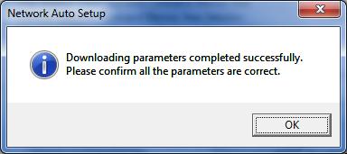
22 Creating the Network Configuration and Transferring Create the network configuration and transfer the settings. 1 Double-click the [0000] Main Rack on the PLC IO Table Window to expand the tree. 2 Right-click 00[1500]CJ1W-NCF82 and select the Unit Setup. 3 The Network Auto Setup Dialog Box is displayed. Check the message on the dialog and if there is no problem, click the OK Button. *If the dialog box is not displayed, select Network Auto Setup from the Network Menu in the PCU Setting Window. Parameter setting view *Close any other dialog box such as the Monitor Dialog Box if displayed. Tree view Network Auto Setup Dialog Box (PCU Setting Window) Additional Information The node addresses 17 onwards are set for CJ1W-NC[]82 in order from the addresses that were set when EtherCAT-compatible devices other than G5-series Servo Drives are connected. 19


23 4 The dialog box on the right is displayed. Select the Fixed Allocations Option and click the OK Button. 5 The network configuration is set up automatically. Confirm that the node address 17 is set for E3NW-ECT Communication Unit for Digital Type Sensor 60 inputs, and click the OK Button. 20


24 6 The dialog box on the right is displayed. Check the message on the dialog and if there is no problem, click the OK Button. *If a confirmation dialog box is displayed, check the message and if there is no problem, click the OK Button. The dialog box on the right is displayed. Check the message on the dialog and if there is no problem, click the OK Button. The dialog box on the right is displayed. Check the message on the dialog and if there is no problem, click the OK Button. 21
 was added.")


25 7 The PCU Setting Window is displayed. Select Network Setting from the project tree on the left side of the Window. Confirm that #17_New Slave E3NW-ECT Communication Unit for Digital Type Sensor 60 inputs(v1.0) was added. *The model and version may differ depending on the device used. 8 9 Click the Remote I/O Input/Output Memory Area Allocation List Tab that is on the right side on the PCU Parameter Setting Window. Confirm that node address #17 is displayed and the I/O Memory Areas are set as follows: Input offset: 0 Input address: 3900 Input size: 10 bytes Output offset: - Output address: - Output size: 0 byte Select Verify Network from the Network Menu. 10 Confirm that Matched is displayed on the Network Verification Result Dialog Box, and click the OK Button. 22


![LED indicators in normal status: [RUN]: Lit green [ERC]: Not lit [ERH]: Not lit [ECAT RUN]: Lit green [ECAT ERR]: Not lit](/docs-images/72/67628266/images/26-3.jpg "[L/A]: Flickering (Upper side of Position Control Unit) The 7-segment display shows as follows during normal EtherCAT")
26 7.4. Checking the EtherCAT Communications Confirm that the EtherCAT communications are performed normally Checking the Connection Status Check the connection status of the EtherCAT network. 1 Check the LED indicators on the Position Control Unit and confirm that the EtherCAT communications are performed normally. LED indicators in normal status: [RUN]: Lit green [ERC]: Not lit [ERH]: Not lit [ECAT RUN]: Lit green [ECAT ERR]: Not lit [L/A]: Flickering (Upper side of Position Control Unit) The 7-segment display shows as follows during normal EtherCAT communications. The 7-segment display: 00 Lit (During EtherCAT communications) (Lower side of Position Control Unit) The status of each LED indicator is shown on the right. 23


![Lit green [L/A IN]:](/docs-images/72/67628266/images/27-3.jpg "Flickering [L/A OUT]:")

![[ERR]: Not lit [SS]:](/docs-images/72/67628266/images/27-5.jpg "Lit green (")
27 2 Check the LED indicators on the Digital Sensor Communication Unit. LED indicators in normal status: [PWR]: Lit green [L/A IN]: Flickering [L/A OUT]: Not lit (last slave) [RUN]: Lit green [ERR]: Not lit [SS]: Lit green (Digital Sensor Communication Unit) 24
 Additional Information For details on errors in the")

28 3 Check the LED indicators on the Distributed Sensor Unit. LED indicators in normal status: [RUN]: Lit green [SS]: Lit green (Distributed Sensor Unit) Additional Information For details on errors in the Position Control Unit, refer to Section 13 Troubleshooting of the CJ-series Position Control Unit Operation Manual (Cat. No. W487). Additional Information For details on errors in the Digital Sensor Communication Unit and the Distributed Sensor Unit, refer to Chapter 8 Troubleshooting and Maintenance of the EtherCAT Digital Sensor Communication Unit Operation Manual (Cat. No. E429). 25

29 Checking Data that are Sent and Received Confirm that correct data are sent and received. Confirm safety sufficiently before monitoring power flow and present value status in the Ladder Section window or before monitoring present values in the Watch window. If force-set/reset or set/reset operations are incorrectly performed by pressing short-cut keys, the devices connected to Output Units may malfunction, regardless of the operating mode of the CPU Unit. 1 Confirm that the PLC is in PROGRAM mode. *If the PLC is not in the PROGRAM mode, change to PROGRAM mode by referring to step 1 of Creating the I/O Table. 2 Select Edit - Memory from the PLC Menu. 26


30 3 Double-click CIO from the list in the PLC Memory Window that is displayed. 4 Select Display - Hexadecimal from the View Menu. 5 Select Monitor from the Online Menu. 6 The Monitor Memory Areas Dialog Box is displayed. Select the CIO Check Box and click the Monitor Button. 27
 IN1[1]: Lit orange (ON) *They are the outputs of the Fiber Amplifier connected to the Digital Sensor Communication Unit.")
 IN1[1]: Lit orange (ON) Digital Sensor Communication Unit Digital Sensor Communication Unit and Fiber Amplifier (Sensor unit No.")

31 7 Check the display contents of the Fiber Amplifier. Fiber Amplifier IN2 IN1 The LED indicators in the figure on the right show as follows: Outputs of Sensor unit No. 1 IN2[2]: Lit orange (ON) IN1[1]: Lit orange (ON) *They are the outputs of the Fiber Amplifier connected to the Digital Sensor Communication Unit. Outputs of Sensor unit No. 2 IN2[2]: Lit orange (ON) IN1[1]: Lit orange (ON) Digital Sensor Communication Unit Digital Sensor Communication Unit and Fiber Amplifier (Sensor unit No. 1) Fiber Amplifier IN2 IN1 *They are the outputs of the Fiber Amplifier connected to the Distributed Sensor Unit. 8 Enter 3900 in the Start Address Field on the CIO Window. Confirm that the start address was changed to The right example shows as follows: CIO 3900: 000F (IN1 and IN2 of Sensor unit No. 1 and 2 are turned ON.) CIO 3902: 0200 (BUSY: OFF, S_ERR: OFF, Number of Sensors setting: 2) CIO 3903: 0002 (Number of Sensors: 2) Distributed Sensor Unit Distributed Sensor Unit and Fiber Amplifier (Sensor unit No. 2) 28

Select Edit - I/O Table and Unit Setup from the PLC Menu of the CX-Programmer.")
32 8. Initialization Method 8. Initialization Method This document explains the setting procedure from the factory default setting. Some settings may not be applicable as described in this document unless you use the devices with the factory default setting Initializing the PLC To initialize the PLC, it is necessary to initialize the CPU Unit and the Position Control Unit. Change to the PROGRAM Mode before initialization Position Control Unit (1)Select Edit - I/O Table and Unit Setup from the PLC Menu of the CX-Programmer. On the PLC IO Table Dialog Box, right-click the Position Control Unit and select Unit Setup from the menu. (2)The PCU Parameter Setting Window is displayed. Select Initialize Memory from the NC Unit Menu. 29

33 8. Initialization Method CPU Unit To initialize the settings of the CPU Unit, select Clear All Memory Areas from the PLC Menu of the CX-Programmer. On the Confirm All Memory Area Clear Dialog Box, select the Initialize Option and click the OK Button. 30
34 9. Revision History 9. Revision History Revision Date of revision Revision reason and revision page code /06/07 First edition 31
35 32
36 2013 P562-E (-)
Machine Automation Controller NJ-series. EtherCAT. Connection Guide. OMRON Corporation. Digital Sensor Communication Unit (E3NW-ECT) P563-E1-01
 P563-E1-01") Machine Automation Controller NJ-series EtherCAT Connection Guide OMRON Corporation Digital Sensor Communication Unit (E3NW-ECT) P563-E1-01 About Intellectual Property Right and Trademarks Microsoft product
Machine Automation Controller NJ-series EtherCAT Connection Guide OMRON Corporation Digital Sensor Communication Unit (E3NW-ECT) P563-E1-01 About Intellectual Property Right and Trademarks Microsoft product
CJ-series DeviceNet Connection Guide OMRON Corporation 3G3RX-V1 Series Inverter
 CJ-series DeviceNet Connection Guide OMRON Corporation 3G3RX-V1 Series Inverter P547-E1-01 About Intellectual Property Rights and Trademarks Microsoft product screen shots reprinted with permission from
Machine Automation Controller NJ-series. EtherNet/IP TM. Connection Guide. OMRON Corporation. CJ2-series Controller P568-E1-01
 Machine Automation Controller NJ-series EtherNet/IP TM Connection Guide OMRON Corporation CJ2-series Controller P568-E1-01 About Intellectual Property Rights and Trademarks Microsoft product screen shots
CJ Series General-purpose Serial Connection Guide OMRON Corporation V500-R2 Series Fixed Laser-Type Barcode Reader
 CJ Series General-purpose Serial Connection Guide OMRON Corporation V500-R2 Series Fixed Laser-Type Barcode Reader P564-E1-01 About Intellectual Property Rights and Trademarks Microsoft product screen
MARS TOHKEN SOLUTION CO.LTD. Fixed Mount 1D/2D Image Reader (TFIR-31LAN Series)
") No.FST-ZTG140008A CJ Series General-purpose Ethernet Connection Guide MARS TOHKEN SOLUTION CO.LTD. Fixed Mount 1D/2D Image Reader (TFIR-31LAN Series) P606-E1-01 About Intellectual Property Rights and Trademarks
No.FST-ZTG140008A CJ Series General-purpose Ethernet Connection Guide MARS TOHKEN SOLUTION CO.LTD. Fixed Mount 1D/2D Image Reader (TFIR-31LAN Series) P606-E1-01 About Intellectual Property Rights and Trademarks
Connection Guide (RS-232C)
") Programmable Controller CJ-series General-purpose Serial Connection Guide (RS-232C) MARS TOHKEN SOLUTION CO.LTD. Fixed Mount 2D Image Reader (MVF-300/500 Series) P679-E1-01 About Intellectual Property
Programmable Controller CJ-series General-purpose Serial Connection Guide (RS-232C) MARS TOHKEN SOLUTION CO.LTD. Fixed Mount 2D Image Reader (MVF-300/500 Series) P679-E1-01 About Intellectual Property
Machine Automation Controller NJ-series. EtherCAT. Connection Guide. OMRON Corporation. GX-series Digital I/O Terminal P517-E1-01
 Machine Automation Controller NJ-series EtherCAT Connection Guide OMRON Corporation GX-series Digital I/O Terminal P517-E1-01 Table of Contents 1. Related Manuals... 1 2. Terms and Definition... 2 3. Remarks...
Machine Automation Controller NJ-series. EtherCAT. Connection Guide. OMRON Corporation. E3X-ECT Sensor Communication Unit (EtherCAT Slave) P529-E1-01
 P529-E1-01") Machine Automation Controller NJ-series EtherCAT Connection Guide OMRON Corporation E3X-ECT Sensor Communication Unit (EtherCAT Slave) P529-E1-01 Table of Contents 1. Related Manuals... 1 2. Terms and
Machine Automation Controller NJ-series EtherCAT Connection Guide OMRON Corporation E3X-ECT Sensor Communication Unit (EtherCAT Slave) P529-E1-01 Table of Contents 1. Related Manuals... 1 2. Terms and
CJ Series EtherNet/IP TM Connection Guide. OMRON Corporation RFID Reader/Writer (V680S-series) P626-E1-01
 P626-E1-01") CJ Series EtherNet/IP TM Connection Guide OMRON Corporation RFID Reader/Writer (V680S-series) P626-E1-01 About Intellectual Property Rights and Trademarks Microsoft product screen shots reprinted with
CJ Series EtherNet/IP TM Connection Guide OMRON Corporation RFID Reader/Writer (V680S-series) P626-E1-01 About Intellectual Property Rights and Trademarks Microsoft product screen shots reprinted with
OMRON Corporation. IO-Link Connection Guide (EtherCAT(R) Host Communications) Machine Automation Controller NJ-series
 Host Communications) Machine Automation Controller NJ-series") Machine Automation Controller NJ-series IO-Link Connection Guide (EtherCAT(R) Host Communications) OMRON Corporation Proximity Sensor (E2E-series IO-Link) [IO-Link Master Unit] OMRON Corporation NX-series
Machine Automation Controller NJ-series IO-Link Connection Guide (EtherCAT(R) Host Communications) OMRON Corporation Proximity Sensor (E2E-series IO-Link) [IO-Link Master Unit] OMRON Corporation NX-series
OMRON Corporation. IO-Link Connection Guide (EtherCAT(R) Host Communications) Machine Automation Controller NJ-series
 Host Communications) Machine Automation Controller NJ-series") Machine Automation Controller NJ-series IO-Link Connection Guide (EtherCAT(R) Host Communications) OMRON Corporation Photoelectric Sensor (E3Z-series IO-Link) [IO-Link Master Unit] OMRON Corporation GX-series
Machine Automation Controller NJ-series IO-Link Connection Guide (EtherCAT(R) Host Communications) OMRON Corporation Photoelectric Sensor (E3Z-series IO-Link) [IO-Link Master Unit] OMRON Corporation GX-series
CJ Series EtherNet/IP TM Connection Guide. ABB Ltd. IRC5 Robot Controller P572-E1-01
 CJ Series EtherNet/IP TM Connection Guide ABB Ltd. IRC5 Robot Controller P572-E1-01 About Intellectual Property Rights and Trademarks Microsoft product screen shots reprinted with permission from Microsoft
CJ Series IO-Link Connection Guide (EtherNet/IP TM Host Communications) OMRON Corporation Proximity Sensor (E2E-series IO-Link)
 OMRON Corporation Proximity Sensor (E2E-series IO-Link)") CJ Series IO-Link Connection Guide (EtherNet/IP TM Host Communications) OMRON Corporation Proximity Sensor (E2E-series IO-Link) [IO-Link Master Unit] OMRON Corporation NX-series IO-Link Master Unit (NX-ILM[][][])
CJ Series IO-Link Connection Guide (EtherNet/IP TM Host Communications) OMRON Corporation Proximity Sensor (E2E-series IO-Link) [IO-Link Master Unit] OMRON Corporation NX-series IO-Link Master Unit (NX-ILM[][][])
Connection Guide HMS Industrial Networks
 Machine Automation Controller NJ-series EtherCAT(R) Connection Guide HMS Industrial Networks Anybus Communicator P560-E1-02 About Intellectual Property Rights and Trademarks Microsoft product screen shots
Machine Automation Controller NJ-series. EtherCAT(R) Connection Guide. Balluff GmbH. Network Interface (BNI ECT-508) P673-E1-01
 Connection Guide. Balluff GmbH. Network Interface (BNI ECT-508) P673-E1-01") Machine Automation Controller NJ-series EtherCAT(R) Connection Guide Balluff GmbH Network Interface (BNI ECT-508) P673-E1-01 About Intellectual Property Rights and Trademarks Microsoft product screen shots
Machine Automation Controller NJ-series EtherCAT(R) Connection Guide Balluff GmbH Network Interface (BNI ECT-508) P673-E1-01 About Intellectual Property Rights and Trademarks Microsoft product screen shots
PHOENIX CONTACT GmbH & Co. KG
 Machine Automation Controller NJ-series EtherCAT(R) Connection Guide PHOENIX CONTACT GmbH & Co. KG I/O SYSTEM (Axioline F Series) P621-E1-01 About Intellectual Property Rights and Trademarks Microsoft
FESTO K.K. IO-Link Connection Guide (EtherCAT(R) Host Communications) Machine Automation Controller NJ-series
 Host Communications) Machine Automation Controller NJ-series") Machine Automation Controller NJ-series IO-Link Connection Guide (EtherCAT(R) Host Communications) FESTO K.K. Proportional pressure regulator valve (VPPM series) [IO-Link Master Unit] OMRON Corporation
Machine Automation Controller NJ-series IO-Link Connection Guide (EtherCAT(R) Host Communications) FESTO K.K. Proportional pressure regulator valve (VPPM series) [IO-Link Master Unit] OMRON Corporation
Machine Automation Controller NJ-series. EtherCAT(R) Connection Guide. OMRON Corporation. Displacement Sensor (ZW-7000 Series) P651-E1-01
 Connection Guide. OMRON Corporation. Displacement Sensor (ZW-7000 Series) P651-E1-01") Machine Automation Controller NJ-series EtherCAT(R) Connection Guide OMRON Corporation Displacement Sensor (ZW-7000 Series) P651-E1-01 About Intellectual Property Rights and Trademarks Microsoft product
Machine Automation Controller NJ-series EtherCAT(R) Connection Guide OMRON Corporation Displacement Sensor (ZW-7000 Series) P651-E1-01 About Intellectual Property Rights and Trademarks Microsoft product
DELTA ELECTRICS, INC.
 Machine Automation Controller NJ-series EtherCAT(R) Connection Guide DELTA ELECTRICS, INC. EtherCAT Slave Remote module (R1-EC Series) P655-E1-01 About Intellectual Property Rights and Trademarks Microsoft
CJ Series EtherNet/IP TM Connection Guide. Yamaha Motor Co., Ltd. Robot Controller (RCX340) P624-E1-01
 P624-E1-01") CJ Series EtherNet/IP TM Connection Guide Yamaha Motor Co., Ltd. Robot Controller (RCX340) P624-E1-01 About Intellectual Property Rights and Trademarks Microsoft product screen shots reprinted with permission
CJ Series EtherNet/IP TM Connection Guide Yamaha Motor Co., Ltd. Robot Controller (RCX340) P624-E1-01 About Intellectual Property Rights and Trademarks Microsoft product screen shots reprinted with permission
Machine Automation Controller NJ-series. EtherCAT. Connection Guide. OMRON Corporation. Displacement Sensor(Confocal Fiber Type) (ZW-CE1) P538-E1-01
 (ZW-CE1) P538-E1-01") Machine Automation Controller NJ-series EtherCAT Connection Guide OMRON Corporation Displacement Sensor(Confocal Fiber Type) (ZW-CE1) P538-E1-01 About Intellectual Property Right and Trademarks Microsoft
Machine Automation Controller NJ-series EtherCAT Connection Guide OMRON Corporation Displacement Sensor(Confocal Fiber Type) (ZW-CE1) P538-E1-01 About Intellectual Property Right and Trademarks Microsoft
Piab AB. IO-Link Connection Guide (EtherCAT(R) Host Communications) Machine Automation Controller NJ-series. Vacuum Ejector (picompact 23 IO-Link)
 Host Communications) Machine Automation Controller NJ-series. Vacuum Ejector (picompact 23 IO-Link)") Machine Automation Controller NJ-series IO-Link Connection Guide (EtherCAT(R) Host Communications) Piab AB Vacuum Ejector (picompact 23 IO-Link) [IO-Link Master Unit] OMRON Corporation NX-series IO-Link
Machine Automation Controller NJ-series IO-Link Connection Guide (EtherCAT(R) Host Communications) Piab AB Vacuum Ejector (picompact 23 IO-Link) [IO-Link Master Unit] OMRON Corporation NX-series IO-Link
CJ Series EtherNet/IP TM Connection Guide. OMRON Corporation NX-series EtherNet/IP Coupler Unit P656-E1-01
 CJ Series EtherNet/IP TM Connection Guide OMRON Corporation NX-series EtherNet/IP Coupler Unit P656-E1-01 About Intellectual Property Rights and Trademarks Microsoft product screen shots reprinted with
EtherCAT(R) Connection Guide IAI Corporation
 Connection Guide IAI Corporation") Machine Automation Controller NJ-series EtherCAT(R) Connection Guide IAI Corporation X-SEL Controller (XSEL-R/S/RX/SX/RXD/SXD) P549-E1-01 About Intellectual Property Rights and Trademarks Microsoft product
Machine Automation Controller NJ-series EtherCAT(R) Connection Guide IAI Corporation X-SEL Controller (XSEL-R/S/RX/SX/RXD/SXD) P549-E1-01 About Intellectual Property Rights and Trademarks Microsoft product
CJ Series EtherNet/IP TM Connection Guide. SMC Corporation Solenoid Valve (SI Unit EX600-SEN#) P657-E1-01
 P657-E1-01") CJ Series EtherNet/IP TM Connection Guide SMC Corporation Solenoid Valve (SI Unit EX600-SEN#) P657-E1-01 About Intellectual Property Rights and Trademarks Microsoft product screen shots reprinted with
CJ Series EtherNet/IP TM Connection Guide SMC Corporation Solenoid Valve (SI Unit EX600-SEN#) P657-E1-01 About Intellectual Property Rights and Trademarks Microsoft product screen shots reprinted with
Connection Guide. SMC Corporation. EtherCAT(R) Machine Automation Controller NJ-series
 Machine Automation Controller NJ-series") Machine Automation Controller NJ-series EtherCAT(R) Connection Guide SMC Corporation EtherCAT Direct input type Step Motor Controller (Servo 24VDC) (JXCE1) P677-E1-01 About Intellectual Property Rights
Machine Automation Controller NJ-series EtherCAT(R) Connection Guide SMC Corporation EtherCAT Direct input type Step Motor Controller (Servo 24VDC) (JXCE1) P677-E1-01 About Intellectual Property Rights
Connection Guide (RS-232C) OMRON Corporation
 OMRON Corporation") Machine Automation Controller NJ-series General-purpose Serial Connection Guide (RS-232C) OMRON Corporation Ultra Small Multi-code Reader (V400-R2 Series) P567-E1-01 About Intellectual Property Rights
Machine Automation Controller NJ-series General-purpose Serial Connection Guide (RS-232C) OMRON Corporation Ultra Small Multi-code Reader (V400-R2 Series) P567-E1-01 About Intellectual Property Rights
CJ Series General-purpose Serial Connection Guide (RS-232C) OMRON Corporation Displacement Sensor (ZW-7000 series)
 OMRON Corporation Displacement Sensor (ZW-7000 series)") CJ Series General-purpose Serial Connection Guide (RS-232C) OMRON Corporation Displacement Sensor (ZW-7000 series) P652-E1-01 About Intellectual Property Rights and Trademarks Microsoft product screen
CJ Series General-purpose Serial Connection Guide (RS-232C) OMRON Corporation Displacement Sensor (ZW-7000 series) P652-E1-01 About Intellectual Property Rights and Trademarks Microsoft product screen
Connection Guide FANUC CORPORATION
 Machine Automation Controller NJ-series EtherCAT(R) Connection Guide FANUC CORPORATION R-30iB Robot Controller P605-E1-01 About Intellectual Property Rights and Trademarks Microsoft product screen shots
CJ Series EtherNet/IP TM Connection Guide. OMRON Corporation Vision System (FZ5 Series) P588-E1-02
 P588-E1-02") CJ Series EtherNet/IP TM Connection Guide OMRON Corporation Vision System (FZ5 Series) P588-E1-02 About Intellectual Property Rights and Trademarks Microsoft product screen shots reprinted with permission
CJ Series EtherNet/IP TM Connection Guide OMRON Corporation Vision System (FZ5 Series) P588-E1-02 About Intellectual Property Rights and Trademarks Microsoft product screen shots reprinted with permission
ORIENTAL MOTOR CO., LTD.
 Machine Automation Controller NJ-series EtherCAT(R) Connection Guide ORIENTAL MOTOR CO., LTD. Network Converter NETC01-ECT -Closed Loop Stepping Motor and Driver Package αstep High-Efficiency AR Series
No. FST-ZTH13079B. Machine Automation Controller NJ-series. EtherCAT Connection Guide. Kollmorgen Corporation Servo Drive (AKD )
") No. FST-ZTH13079B Machine Automation Controller NJ-series EtherCAT Connection Guide Kollmorgen Corporation Servo Drive (AKD ) About Intellectual Property Rights and Trademarks Microsoft product screen
No. FST-ZTH13079B Machine Automation Controller NJ-series EtherCAT Connection Guide Kollmorgen Corporation Servo Drive (AKD ) About Intellectual Property Rights and Trademarks Microsoft product screen
Omron Adept Technologies,Inc.
 Machine Automation Controller NJ-series EtherNet/IP TM Connection Guide Omron Adept Technologies,Inc. Adept Robot of eplc P649-E1-01 About Intellectual Property Rights and Trademarks Microsoft product
Connection Guide (RS-232C)
") Machine Automation Controller NJ-series General-purpose Seriarl Connection Guide (RS-232C) OMRON Corporation G9SP Safety Controller P545-E1-01 About Intellectual Property Rights and Trademarks Microsoft
Machine Automation Controller NJ-series General-purpose Seriarl Connection Guide (RS-232C) OMRON Corporation G9SP Safety Controller P545-E1-01 About Intellectual Property Rights and Trademarks Microsoft
Machine Automation Controller NJ-series. EtherNet/IP TM. Connection Guide. OMRON Corporation. Displacement Sensor (ZW-7000 series) P653-E1-01
 P653-E1-01") Machine Automation Controller NJ-series EtherNet/IP TM Connection Guide OMRON Corporation Displacement Sensor (ZW-7000 series) P653-E1-01 About Intellectual Property Rights and Trademarks Microsoft product
Machine Automation Controller NJ-series EtherNet/IP TM Connection Guide OMRON Corporation Displacement Sensor (ZW-7000 series) P653-E1-01 About Intellectual Property Rights and Trademarks Microsoft product
Connection Guide IAI Corporation
 Machine Automation Controller NJ-series EtherCAT Connection Guide IAI Corporation Controller SCON-CA P585-E1-01 About Intellectual Property Rights and Trademarks Microsoft product screen shots reprinted
Machine Automation Controller NJ-series. EtherCAT(R) Connection Guide. IAI Corporation. ACON/ACON-CA/ PCON/PCON-CA/ DCON-CA Controller P584-E1-02
 Connection Guide. IAI Corporation. ACON/ACON-CA/ PCON/PCON-CA/ DCON-CA Controller P584-E1-02") Machine Automation Controller NJ-series EtherCAT(R) Connection Guide IAI Corporation ACON/ACON-CA/ PCON/PCON-CA/ DCON-CA Controller P584-E1-02 About Intellectual Property Rights and Trademarks Microsoft
Machine Automation Controller NJ-series EtherCAT(R) Connection Guide IAI Corporation ACON/ACON-CA/ PCON/PCON-CA/ DCON-CA Controller P584-E1-02 About Intellectual Property Rights and Trademarks Microsoft
Connection Guide (RS-232C) OMRON Corporation
 OMRON Corporation") Machine Automation Controller NJ-series General-purpose Serial Connection Guide (RS-232C) OMRON Corporation ZW-series Displacement Sensor P559-E1-01 About Intellectual Property Right and Trademarks Microsoft
Machine Automation Controller NJ-series General-purpose Serial Connection Guide (RS-232C) OMRON Corporation ZW-series Displacement Sensor P559-E1-01 About Intellectual Property Right and Trademarks Microsoft
Machine Automation Controller NJ-series. EtherNet/IP TM. Connection Guide. OMRON Corporation. FZ5-series Vision System P589-E1-01
 Machine Automation Controller NJ-series EtherNet/IP TM Connection Guide OMRON Corporation FZ5-series Vision System P589-E1-01 About Intellectual Property Rights and Trademarks Microsoft product screen
Connection Guide (RS-232C) OMRON Corporation
 OMRON Corporation") Machine Automation Controller NJ-series General-purpose Serial Connection Guide (RS-232C) OMRON Corporation V750 series RFID System P544-E1-01 About Intellectual Property Right and Trademarks Microsoft
Machine Automation Controller NJ-series General-purpose Serial Connection Guide (RS-232C) OMRON Corporation V750 series RFID System P544-E1-01 About Intellectual Property Right and Trademarks Microsoft
Rockwell Automation ControlLogix 1756-L71 EtherNet/IP Connection Guide. OMRON Corporation. RFID System V680S. V680S RFID System. Cat. No.
 Rockwell Automation ControlLogix 1756-L71 EtherNet/IP Connection Guide OMRON Corporation RFID System V680S V680S RFID System Cat. No. P242I-E-02 About Intellectual Property Right and Trademarks Microsoft
EtherCAT Digital Sensor Communication Unit
 E3NW-ECT EtherCAT Digital Sensor Communication Unit Operation Manual E429-E1-04 OMRON, 2013 All rights reserved. No part of this publication may be reproduced, stored in a retrieval system, or transmitted,
Sysmac Studio Version 1
 Automation Software Sysmac Studio Version 1 Drive Functions Operation Manual SYSMAC-SE2 I589-E1-04 NOTE All rights reserved. No part of this publication may be reproduced, stored in a retrieval system,
Connection Guide (TCP/IP) OMRON Corporation
 OMRON Corporation") Machine Automation Controller NJ-series General-purpose Ethernet Connection Guide (TCP/IP) OMRON Corporation V750 series RFID System P543-E1-01 About Intellectual Property Right and Trademarks Microsoft
Machine Automation Controller NJ-series General-purpose Ethernet Connection Guide (TCP/IP) OMRON Corporation V750 series RFID System P543-E1-01 About Intellectual Property Right and Trademarks Microsoft
IO-Link System. User s Manual W570-E1-04
 IO-Link System User s Manual W570-E1-04 NOTE All rights reserved. No part of this publication may be reproduced, stored in a retrieval system, or transmitted, in any form, or by any means, mechanical,
IO-Link System. User s Manual W570-E1-03
 IO-Link System User s Manual W570-E1-03 NOTE All rights reserved. No part of this publication may be reproduced, stored in a retrieval system, or transmitted, in any form, or by any means, mechanical,
Omron Adept Technologies,Inc.
 Machine Automation Controller NJ-series EtherNet/IP TM Connection Guide Omron Adept Technologies,Inc. Adept Robot of eplcio P650-E1-01 About Intellectual Property Rights and Trademarks Microsoft product
Startup Guide For EtherCAT Communication Coupler Safety Controllers and I/O Units
 Programmable Multi-Axis Controller Startup Guide For EtherCAT Communication Coupler Safety Controllers and I/O Units CK3E- NY51 -A O025-E1-01 About Copyrights and Trademarks Microsoft product screen shots
Cat. No. W585-E1-02 SYSMAC. NX-IO Configurator CXONE-AL D-V4 OPERATION MANUAL
 Cat. No. W585-E1-02 SYSMAC NX-IO Configurator CXONE-AL D-V4 OPERATION MANUAL NOTE All rights reserved. No part of this publication may be reproduced, stored in a retrieval system, or transmitted, in any
Practices Guide. Programmable Terminal NB-series. - Disable/Enable communication with PLCs in Run -time
 Programmable Terminal NB-series Practices Guide - Disable/Enable communication with PLCs in Run -time - Print Screen image + Display Component information - Project file management NB3Q-TW01B NB5Q-TW01B
SYSMAC CV-series CV500/CV1000/CV2000/CVM1 Programmable Controllers
 Cat. No. W205-E1-04 SYSMAC CV-series CV500/CV1000/CV2000/CVM1 Programmable Controllers SYSMAC CV-series CV500/CV1000/CV2000/CVM1 Programmable Controllers Operation Manual: Host Link System, CV500-LK201
Machine Automation Controller. NJ-series. Troubleshooting Manual NJ NJ NJ W503-E1-01
 Machine Automation Controller NJ-series Troubleshooting Manual NJ501-1300 NJ501-1400 NJ501-1500 W503-E1-01 OMRON, 2011 All rights reserved. No part of this publication may be reproduced, stored in a retrieval
The Next-generation Sensor Networking Units That Revolutionize the Workplace from Introduction and Startup though Operation. Fiber Units.
 Sensor Communications Unit CSM DS_E_1_1 The Next-generation Sensor Networking Units That Revolutionize the Workplace from Introduction and Startup though Operation Low initial cost achieved by distributed
Operation Manual SFC Programming
 Cat. No. W469-E1-03 SYSMAC CX-Programmer Ver. 8.0 WS02-CXPC1-V8 Operation Manual SFC Programming CX-Programmer Ver. 8.0 WS02-CXPC1-V8 Operation Manual SFC Programming Revised June 2008 ii TABLE OF CONTENTS
SYSMAC CJ-series Position Control Units with EtherCAT interface
 SYSDRIVE STOP RESET SYSMAC CJ-series Position Control Units with EtherCAT interface CJ1W-NC@81/@82 Preeminent control performance and easy operation feature of EtherCAT improve the production efficiency.
1. Overview of YC-Link/E Overview Part names of YC-Link/E compatible units Installation and settings 3
 CONTENTS YC-Link/E User s Manual 1. Overview of YC-Link/E 1 1.1 Overview 1 1.2 Part names of YC-Link/E compatible units 2 2. Installation and settings 3 2.1 Connecting the LAN cables 3 2.2 LAN cable type
EtherCAT Remote I/O Terminal GX series
 EtherCAT Remote I/O Terminal GX series Digital I/O Terminal 2-tier Terminal Block Type Digital I/O Terminal 3-tier Terminal Block Type Digital I/O Terminal e-con Connector Type Analog I/O Terminal 2-tier
CJ-series Position Control Units with EtherCAT interface
 CJ-series Position Control Units with EtherCAT interface CJ1W-NC@81/@82 Preeminent control performance and easy operation feature of EtherCAT improve the production efficiency. The EtherCAT communications
CJ-series Position Control Units with EtherCAT interface
 CJ-series Position Control Units with EtherCAT interface Preeminent control performance and easy operation feature of EtherCAT improve the production efficiency. The EtherCAT communications with 100Mbps
CJ Series EtherNet/IP Connection Guide OMRON Corporation ZW-series Displacement Sensor
 No. FST-ZTH120036A CJ Series EtherNet/IP Connection Guide OMRON Corporation ZW-series Displacement Sensor P536-E1-01 About Intellectual Property Right and Trademarks Microsoft product screen shots reprinted
STD_HLS36USB_V1.0E. HLS(MKY36)USB Unit. HLS-36USB Product Manual
USB Unit. HLS-36USB Product Manual") STD_HLS36USB_V1.0E HLS(MKY36)USB Unit HLS-36USB Product Manual Introduction Thank you for purchasing the StepTechnica product. Please check the bundled items. This product consists of the following contents.
STD_HLS36USB_V1.0E HLS(MKY36)USB Unit HLS-36USB Product Manual Introduction Thank you for purchasing the StepTechnica product. Please check the bundled items. This product consists of the following contents.
CJ Series EtherNet/IP TM Connection Guide. OMRON Corporation Vision System (FH Series) P575-E1-02
 P575-E1-02") CJ Series EtherNet/IP TM Connection Guide OMRON Corporation Vision System (FH Series) P575-E1-02 About Intellectual Property Rights and Trademarks Microsoft product screen shots reprinted with permission
CJ Series EtherNet/IP TM Connection Guide OMRON Corporation Vision System (FH Series) P575-E1-02 About Intellectual Property Rights and Trademarks Microsoft product screen shots reprinted with permission
MG50-EC MG51. Instruction Manual. EtherCAT Interface unit Main module. Distribution module
 EtherCAT Interface unit Main module MG50-EC Distribution module MG51 Read all the instructions in the manual carefully before use and strictly follow them. Keep the manual for future references. Instruction
Startup Guide for Multi-axis Setup and Tuning
 AC Servo System 1S-series Startup Guide for Multi-axis Setup and Tuning R88M-1L[]/-1M[] (AC Servomotors) R88D-1SN[]-ECT (AC Servo Drives) SYSMAC-SE20[][] (Automation Software) I827-E1-01 NOTE All rights
ID Sensor Units. Operation Manual for NJ-series CPU Unit. Machine Automation Controller CJ-series CJ1W-V680C11 CJ1W-V680C12.
 Machine Automation Controller CJ-series ID Sensor Units Operation Manual for NJ-series CPU Unit CJ1W-V680C11 CJ1W-V680C12 ID Sensor Units Z317-E1-03 OMRON, 2011 All rights reserved. No part of this publication
EtherNet/IP Monitor Tool Operation Manual
 EtherNet/IP Monitor Tool Operation Manual Introduction This manual documents the operating procedures of the EtherNet/IP Monitor Tool. It does not contain other information, such as precautions. In actual
EtherCAT master * Output port CPU Unit
 CJ-series EtherCAT Slave Unit CSM DS_E_2_1 Hi-speed I/O link based on EtherCAT NJ/CJ Series available as subsystem controller on EtherCAT. Interface with multiple networks such as EtherCAT and DeviceNet.
Cat. No. W481-E1-02. ERT1 Series. EtherNet/IP Slave Units OPERATION MANUAL
 Cat. No. W481-E1-02 ERT1 Series EtherNet/IP Slave Units OPERATION MANUAL ERT1 Series EtherNet/IP Slave Units Operation Manual Revised November 2010 iv Notice: OMRON products are manufactured for use according
DIGITAL TRANSMITTER CANopen Interface OPT-563B-71 Instruction Manual
 DIGITAL TRANSMITTER CANopen Interface OPT-563B-71 Instruction Manual EN294-1634B Introduction Thank you for your purchasing the Minebea OPT-563B-71 Digital Transmitter with CANopen interface for optical
Analog Input Unit. MACH No. MODE. Regulator. Servocontroller. Variable speed controller. Chart recorder
 CJ Series Analog I/O Unit CSM_CJ1W-AD_DA_MAD_DS_E_1_1 For Various Analog I/Os Analog Input Units for converting analog input signals into binary data Analog Output Units for converting binary data into
E3X-DRT21 (DeviceNet) E3X-SRT21 (CompoBus/S) E3X-CIF11 (RS-422) Fiber Amplifier Sensor Communication Units OPERATION MANUAL
 E3X-SRT21 (CompoBus/S) E3X-CIF11 (RS-422) Fiber Amplifier Sensor Communication Units OPERATION MANUAL") Cat. No. Z152-E1-02 E3X-DRT21 (DeviceNet) E3X-SRT21 (CompoBus/S) E3X-CIF11 (RS-422) Fiber Amplifier Sensor Communication Units OPERATION MANUAL E3X-DRT21 (DeviceNet) E3X-SRT21 (CompoBus/S) E3X-CIF11 (RS-422)
Cat. No. Z152-E1-02 E3X-DRT21 (DeviceNet) E3X-SRT21 (CompoBus/S) E3X-CIF11 (RS-422) Fiber Amplifier Sensor Communication Units OPERATION MANUAL E3X-DRT21 (DeviceNet) E3X-SRT21 (CompoBus/S) E3X-CIF11 (RS-422)
Machine ZX-T Automation Series Controller CJ-series PROFIBUS Master Unit. Operation Manual for NJ-series CPU Unit CJ1W-PRM21. PROFIBUS Master Unit
 Machine ZX-T Automation Series Controller CJ-series PROFIBUS Master Unit Operation Manual for NJ-series CPU Unit CJ1W-PRM21 PROFIBUS Master Unit W509-E2-01 Introduction Introduction Thank you for purchasing
Machine Automation Controller CJ-series. Units. EtherNet/IP TM. Operation Manual for NJ-series CPU Unit CJ1W-EIP21. EtherNet/IP Units W495-E1-05
 Machine Automation Controller CJ-series EtherNet/IP TM Units Operation Manual for NJ-series CPU Unit CJ1W-EIP21 EtherNet/IP Units W495-E1-05 OMRON, 2012 All rights reserved No part of this publication
Machine ZX-T Automation Series Controller CJ-series PROFIBUS Slave Unit. Operation Manual for NJ-series CPU Unit CJ1W-PRT21. PROFIBUS Slave Unit
 Machine ZX-T Automation Series Controller CJ-series PROFIBUS Slave Unit Operation Manual for NJ-series CPU Unit CJ1W-PRT21 PROFIBUS Slave Unit W510-E2-01 Introduction Introduction Thank you for purchasing
Operation Software. CNC Operator. Operation Manual SYSMAC-RTNC O032-E1-02
 Operation Software CNC Operator Operation Manual SYSMAC-RTNC O032-E1-02 NOTE All rights reserved. No part of this publication may be reproduced, stored in a retrieval system, or transmitted, in any form,
Machine Automation Controller CJ-series. DeviceNet Units. Operation Manual for NJ-series CPU Unit CJ1W-DRM21. DeviceNet Units W497-E1-03
 Machine Automation Controller CJ-series DeviceNet Units Operation Manual for NJ-series CPU Unit CJ1W-DRM21 DeviceNet Units W497-E1-03 OMRON, 2011 All rights reserved. No part of this publication may be
Supplementary device manual EtherCAT interface in the AS-i controllere A AC1391 AC1392
 Supplementary device manual EtherCAT interface in the AS-i controllere A AC1391 AC139 firmware version RTS.x target from 15 for CoDeSys from version.3 English 739071_00_UK 01-0- Contents Revision: 16 December
DX200 OPTIONS MECHATROLINK-II COMMUNICATION FUNCTION INSTRUCTIONS
 DX200 OPTIONS MECHATROLINK-II COMMUNICATION FUNCTION INSTRUCTIONS (FOR MP2110-ET3 MADE BY YASKAWA ELECTRIC CORPORATION ) Upon receipt of the product and prior to initial operation, read these instructions
OPERATION MANUAL Function Blocks/ Structured Text
 Cat. No. W447-E1-09 SYSMAC CX-Programmer Ver. 9 WS02-CXPC1-V9 OPERATION MANUAL Function Blocks/ Structured Text CX-Programmer Ver. 9.@ WS02-CXPC1-V9 Operation Manual Function Blocks/Structured Text Revised
SYSMAC CS-series MECHATROLINK-II-compatible Position Control Units
 SYSMAC CS-series MECHATROLINK-II-compatible Position Control Units CSM_CS1W-NC_71_DS_E_7_4 Decrease TCO with Simple Operation, Reduced Wiring, Batch Settings, and Batch Management Control Servos for up
Safety Network Controller NX-series Communication Control Unit User's Manual. Built-in Function NX-CSG. Communication Control Unit
 Safety Network Controller NX-series Communication Control Unit User's Manual Built-in Function NX-CSG Communication Control Unit NOTE (1) All rights reserved. No part of this publication may be reproduced,
CX-Designer Ver.3 CSM_CX-Designer_DS_E_5_5
 FA Integrated Tool Package CX-One Ver.3 CSM DS_E_5_5 Intuitive operability will increase programming efficiency from screen data creation to debugging for NS series. is the programming software for debugging
Sysmac Library Omron's control expertise changes programming
 SYSMAC-XR@@@ Omron's control expertise changes programming 2 Various software components help reduce programming time The is a collection of software functional components that can be used in programs
1. Introduction. Be sure to read the release notes in section 10 before operating the Unit.
 1. Introduction This manual describes the ways of configuring and monitoring the operation of the PROFINET IO Controller CJ1W-PNT Sample Version V0.00 V67.06 V0.00 (Internal release V6.29). Be sure to
Anybus CompactCom 40 Diagnostic Events for EtherCAT SCM ENGLISH
 Anybus CompactCom 40 Diagnostic Events for EtherCAT SCM-1202 070 1.0 ENGLISH Important User Information Liability Every care has been taken in the preparation of this document. Please inform HMS Industrial
Machine Automation Controller CJ-series. Units. EtherNet/IP TM. Operation Manual for NJ-series CPU Unit CJ1W-EIP21. EtherNet/IP Units W495-E1-07
 Machine Automation Controller CJ-series EtherNet/IP TM Units Operation Manual for NJ-series CPU Unit CJ1W-EIP21 EtherNet/IP Units W495-E1-07 NOTE All rights reserved No part of this publication may be
B Programmable Terminal NB Series. Practice Guide. Sysmac Studio Variable Table Import NB3Q-TW01B NB5Q-TW01B NB7W-TW01B NB10W-TW01B
 B-181206 Programmable Terminal NB Series Practice Guide Sysmac Studio Variable Table Import NB3Q-TW01B NB5Q-TW01B NB7W-TW01B NB10W-TW01B Introduction This guide provides reference information when designing
Cat. No. W436-E1-09 SYSMAC CXONE-AL_C-V3/ CXONE-AL_D-V3. CX-Motion-NCF Ver. 1.9 OPERATION MANUAL
 Cat. No. W436-E1-09 SYSMAC CXONE-AL_C-V3/ CXONE-AL_D-V3 CX-Motion-NCF Ver. 1.9 OPERATION MANUAL CXONE-AL@@C-V3/ CXONE-AL@@D-V3 CX-Motion-NCF Ver. 1.9 Operation Manual Revised September 2009 iv Notice:
Before using this product, you must read Introduction and Safety Cautions.
 Cat. No. R135-E1-02 CX-One CD-ROM contains a setup manual PDF file. The Setup manual of CX-One is stored in the following file. Disk1: CX-One_Manuals English CX-One Setup Manual W444-E1-02.pdf / / Before
CPU Unit Motion Control
 Machine Automation Controller NJ-series CPU Unit Motion Control User s Manual NJ501-1300 NJ501-1400 NJ501-1500 CPU Unit W507-E1-01 OMRON, 2011 All rights reserved. No part of this publication may be reproduced,
Maintenance information. DRT2-series. Remote I/O Terminals Relay Output Terminals. DRT2-series Smart Slave Analog I/O Terminals.
 CS-series Net Unit CSM DS_E_5_3 A Net Unit for the CS Series That Boasts Industry-leading Performance and Functions Features Allows control of up to 32,000 points (2,000 words) per master, and ensures
User's Manual. CK3M-series Programmable Multi-Axis Controller Hardware CK3M-CPU1 0 CK3W-PD028 CK3W-AX1111 /AX1212. Programmable Multi-Axis Controller
 CK3M-series Programmable Multi-Axis Controller Hardware User's Manual CK3M-CPU1 0 CK3W-PD028 CK3W-AX1111 /AX1212 Programmable Multi-Axis Controller O034-E1-01 NOTE All rights reserved. No part of this
CX-One Ver.4 CSM_CX-One_DS_E_8_2
 FA Integrated Tool Package CX-One CSM_CX-One_DS_E_8_2 Greater Integration with the CX-One The CX-One is a comprehensive software package that integrates PLC Programming Software with Support Software for
SANYO DENKI Servo Amplifier SANMOTION R and Pro-face AGP-3****-CA1M/LT Connection Procedure. Instruction Manual. Version1.0 (
 SANYO DENKI Servo Amplifier SANMOTION R and Pro-face AGP-3****-CA1M/LT Connection Procedure Instruction Manual Version1.0 (2009.2.25) Table of Contents 1 Applicable devices... 1 2 Installation of GP-Pro
Table of Contents. Chapter 1 Overview and Installation of CX-One. Chapter 2 Example of PLC System Construction by CX-One
 -Please be sure to read and understand Precautions and Introductions in CX-One Setup Manual (W463-E1), CX-Programmer Operation Manual(W446-E1) and CX-Integrator Operation Manual (W464-E1) before using
SPiiPlusEC Network Manager Installation Guide November2014 Document Revision: 02
 SPiiPlusEC Network Manager Installation Guide November2014 Document Revision: 02 SPiiPlusEC Release Date: November2014 Copyright ACS Motion Control Ltd.2014. All rights reserved. Changes are periodically
User s Manual for Communications Settings
 Displacement Sensor series Confocal Fiber Type Displacement Sensor ZW-7000@ ZW-5000@ Z363-E1-05 Introduction Thank you for purchasing the Series. This manual provides information regarding functions, performance
EtherCAT Slave. X-gateway Interface Addendum. Doc: HMSI , Rev: Connecting Devices TM
 X-gateway Interface Addendum EtherCAT Slave Connecting Devices TM HALMSTAD CHICAGO KARLSRUHE TOKYO BEIJING MILANO MULHOUSE COVENTRY PUNE COPENHAGEN HMS Industrial Networks Mailing address: Box 4126, 300
CX-One Ver.4. FA Integrated Tool Package CX-One. Greater Integration with the CX-One. Features
 FA Integrated Tool Package CX-One CX-One Ver.4 CSM_CX-One_DS_E_2_1 Greater Integration with the CX-One The CX-One is a comprehensive software package that integrates PLC Programming Software with Support
NU-DN1. User s Manual. DeviceNet Compatible Network Unit
 96148E DeviceNet Compatible Network Unit NU-DN1 User s Manual Read this manual before use. Keep this manual in a safe place for future reference. Compatible with FS-N10 Series, LV-N10 Series and PS-N10