Connection Guide (TCP/IP) OMRON Corporation
|
|
|
- Christina Stafford
- 5 years ago
- Views:
Transcription
 OMRON Corporation V750 series RFID System")
1 Machine Automation Controller NJ-series General-purpose Ethernet Connection Guide (TCP/IP) OMRON Corporation V750 series RFID System P543-E1-01
2 About Intellectual Property Right and Trademarks Microsoft product screen shots reprinted with permission from Microsoft Corporation. Windows is a registered trademark of Microsoft Corporation in the USA and other countries. EtherCAT is registered trademark and patented technology, licensed by Beckhoff Automation GmbH, Germany. Ethernet is a registered trademark of Xerox Corporation. Java and all Java-related trademarks and logos are trademarks or registered trademarks of Oracle Corporation, Inc., in the USA and other countries. Company names and product names in this document are the trademarks or registered trademarks of their respective companies.
3 Table of Contents 1. Related Manuals Terms and Definition Remarks Overview Applicable Devices and Support Software Applicable Devices Device Configuration Ethernet Communications Settings Ethernet Communications Settings Example of Checking Connection Connection Procedure Work Flow Setting Up the RFID Reader/Writer Setting Up the Controller Connection Status Check Initialization Method Controller RFID Reader/Writer Overview Destination Device Command Error Detection Processing Variables ST Program Timing Charts Error Process Revision History... 74
4 1. Related Manuals 1. Related Manuals The table below lists the manuals related to this document. To ensure system safety, make sure to always read and heed the information provided in all Safety Precautions, Precautions for Safe Use, and Precaution for Correct Use of manuals for each device which is used in the system. Cat. No. Model Manual name W500 W501 W506 NJ501-[][][][] NJ301-[][][][] NJ501-[][][][] NJ301-[][][][] NJ501-[][][][] NJ301-[][][][] NJ-series CPU Unit Hardware User's Manual NJ-series CPU Unit Software User's Manual NJ-series CPU Unit Built-in EtherNet/IP Port User's Manual W504 SYSMAC-SE2[][][] Sysmac Studio Version 1 Operation Manual W502 Z235 NJ501-[][][][] NJ301-[][][][] V750-BA50C04-US V740-HS01[][] NJ-series Instructions Reference Manual V750-series UHF RFID System User s Manual 1
5 2. Terms and Definition 2. Terms and Definition Terms IP address Socket Connect processing/ Accept processing Keep-alive function Linger function Explanation and Definition Ethernet uses an IP address to perform communications. The IP address (Internet Protocol address) is an address that is used to identify a node (host computer or controller, etc.) on Ethernet. IP addresses must be set and managed so they do not overlap. A socket is an interface that allows you to directly use TCP or UDP functions from the user program. The socket services enable data exchange with destination nodes. The NJ-series Machine Automation Controller performs socket communications by using the standard socket service instructions. Open processing is executed on each node to connect the TCP socket. The open method depends on whether the node is opened as a server or client. In this document, the processing executed to open a node as a client is called "connect processing" and the processing executed to open as a server is called "accept processing". When the keep-alive function is used with TCP/IP socket services, the keep-alive communications frame is used to check the status of the connection with the destination node (either a server or client) if there are no communications during the specified time interval. Checks are executed at a certain interval, and if there is no response to any of them then the connection is terminated. This is an option for the TCP socket that enables immediate connect processing using the same port number without waiting until the port number opens after RST data is sent when the TCP socket closes. If the linger option is not specified, FIN data will be sent when a TCP socket is closed, and then approximately 1 minute will be required to confirm the transmission and perform other closing management with the destination node. Therefore, it may not be possible to immediately use TCP sockets with the same port number. 2
6 3. Remarks 3. Remarks (1) Understand the specifications of devices which are used in the system. Allow some margin for ratings and performance. Provide safety measures, such as installing safety circuit in order to ensure safety and minimize risks of abnormal occurrence. (2) To ensure system safety, always read and heed the information provided in all Safety Precautions, Precautions for Safe Use, and Precaution for Correct Use of manuals for each device used in the system. (3) The users are encouraged to confirm the standards and regulations that the system must conform to. (4) It is prohibited to copy, to reproduce, and to distribute a part of or whole part of this document without the permission of OMRON Corporation. (5) This document provides the latest information as of April The information on this manual is subject to change for improvement without notice. 3


7 3. Remarks The following notation is used in this document. Precautions for Safe Use Indicates precautions on what to do and what not to do to ensure using the product safely. Precautions for Correct Use Indicates precautions on what to do and what not to do to ensure proper operation and performance. Additional Information Provides useful information. Additional information to increase understanding or make operation easier. 4
8 4. Overview 4. Overview This document describes the procedure for connecting the RFID Reader/Writer (V750 series) of OMRON Corporation (hereinafter referred to as OMRON) to the NJ-series Machine Automation Controller (hereinafter referred to as Controller) through Ethernet, and provides the procedure for checking their connection. Refer to the Ethernet communications settings of the prepared project file to understand the setting procedure and key points to connect the devices via Ethernet. The user program in this project file is used to check the Ethernet connection by sending/receiving the message of GETR TYP FWV (read the product type and firmware version of the memory data) to/from the destination device. Prepare the latest Sysmac Studio project file beforehand. For information on how to obtain the file, contact your OMRON representative. Name File name Version Sysmac Studio project file OMRON_V750_ETN(TCP)_EV101.smc Ver.1.01 (extension: smc) *Hereinafter, the Sysmac Studio project file is referred to as the project file. The user program in the project file is referred to as the program. This document aims to explain the wiring method and communications settings necessary to connect the corresponding devices and provide the setting procedure. The program used in this document is designed to check if the connection was properly established, and is not designed to be constantly used at a site. Therefore, functionality and performances are not sufficiently taken into consideration. When you construct an actual system, please use the wiring method, communications settings and setting procedure described in this document as a reference and design a new program according to your application needs. 5
9 5. Applicable Devices and Support Software 5. Applicable Devices and Support Software 5.1. Applicable Devices The applicable devices are given below. Manufacturer Name Model OMRON NJ-series CPU Unit NJ501-[][][][] NJ301-[][][][] OMRON RFID Reader/Writer V750-BA50C04-US (complies with FCC and EN) OMRON Antenna V740-HS01[][] OMRON Antenna cable V740-A01 [][]M Additional Information As applicable devices above, the devices with the models and versions listed in Section 5.2. are actually used in this document to describe the procedure for connecting devices and checking the connection. You cannot use devices with versions lower than the versions listed in Section 5.2. To use the above devices with versions not listed in Section 5.2 or versions higher than those listed in Section 5.2, check the differences in the specifications by referring to the manuals before operating the devices. Additional Information This document describes the procedure to establish the network connection. Except for the connection procedure, it does not provide information on operation, installation or wiring method. It also does not describe the function or operation of the devices. Refer to the manuals or contact your OMRON representative. 6
 NJ501-1500 Personal computer")
![(Built-in EtherNet/IP port) (Sysmac Studio installed, OS: Windows 7) USB cable Switching hub W4S1-05C Antenna (V740-HS01CA) Antenna Cable (V740-A01 [][]M) AC Adapter (included) Manufacturer Name](/docs-images/96/127250241/images/10-1.jpg "Model Version OMRON NJ-series CPU Unit NJ501-1500 Ver.1.03 (Built-in EtherNet/IP port) OMRON Power Supply Unit NJ-PA3001 OMRON Switching Hub W4S1-05C Ver.1.0 OMRON Sysmac Studio SYSMAC-SE2[][][] Ver.")
 - LAN cable - OMRON RFID Reader/Writer V750-BA50C04-US Ver.102-10 2-103-0 OMRON Antenna (Circular) (4 max.")
10 5. Applicable Devices and Support Software 5.2. Device Configuration The hardware components to reproduce the connection procedure of this document are as follows: LAN cable RFID Reader/Writer (V750-BA50C04-US) NJ Personal computer (Built-in EtherNet/IP port) (Sysmac Studio installed, OS: Windows 7) USB cable Switching hub W4S1-05C Antenna (V740-HS01CA) Antenna Cable (V740-A01 [][]M) AC Adapter (included) Manufacturer Name Model Version OMRON NJ-series CPU Unit NJ Ver.1.03 (Built-in EtherNet/IP port) OMRON Power Supply Unit NJ-PA3001 OMRON Switching Hub W4S1-05C Ver.1.0 OMRON Sysmac Studio SYSMAC-SE2[][][] Ver.1.04 OMRON Sysmac Studio project file OMRON_V750_ETN(TCP) Ver.1.01 _EV101.smc - Personal computer - (OS:Windows7) - USB cable - (USB 2.0 type B connector) - LAN cable - OMRON RFID Reader/Writer V750-BA50C04-US Ver OMRON Antenna (Circular) (4 max.) V740-HS01CA OMRON Antenna cable V740-A01[][]M OMRON AC Adapter (included) - Precautions for Correct Use Prepare the latest project file in advance. To obtain the file, contact your OMRON representative. Precautions for Correct Use Update the Sysmac Studio to the version specified in this section or higher version using the auto update function. If a version not specified in this section is used, the procedures described in Section 7 and subsequent sections may not be applicable. In that case, use the equivalent procedures described in the Sysmac Studio Version 1 Operation Manual (Cat.No. W504). 7
11 5. Applicable Devices and Support Software Additional Information It may not be possible to reproduce the same operation with different devices or versions. Check the configuration, model and version. If they are different from your configuration. Contact your OMRON representative. Additional Information In this document, a USB is used to connect with the Controller. For information on how to install a USB driver, refer to A-1 Driver Installation for Direct USB Cable Connection of the Sysmac Studio Version 1 Operation Manual (Cat.No. W504). 8
12 6. Ethernet Communications Settings 6. Ethernet Communications Settings This section describes the specifications such as communication parameters and variables that are set in this document. Additional Information To perform communications without using the settings described in this section, you need to modify the program. For information on the program, refer to Section Ethernet Communications Settings The settings required for Ethernet communications are shown below Communications Settings between the Personal Computer and the RFID Reader/Writer The setting example below is used to explain the procedure for setting the RFID Reader/Writer by using the personal computer. Setting item Personal computer used for setting RFID Reader/Writer IP address (Default) Subnet mask (Default) Gateway (Default) *In this document, the gateway setting is unnecessary because the connection is made in the same segment Communications Settings between the Controller and the RFID Reader/Writer The setting example below is used to explain the procedure for connecting the Controller to the RFID Reader/Writer. Setting item NJ RFID Reader/Writer IP address Subnet mask (Default) Gateway (Default) Host name - V750-BA50C04-US (Default) Domain name - Blank (Default) DHCP - OFF (Default) TCP/IP port (This is set by the program.) 7090 (Default) *In this document, the gateway setting is unnecessary because the connection is made in the same segment. *This project file uses the default settings (keep-alive: use, linger option: Do not use) of the keep-alive and linger option functions for the TCP socket communications. Use these functions according to the system when necessary. 9
13 6. Ethernet Communications Settings 6.2. Example of Checking Connection This document shows an example of a Structured Text (ST) program in which the Controller executes the connect processing, send/receive processing, and close processing on the RFID Reader/Writer. The Controller and RFID Reader/Writer send and receive the message of GETR TYP FWV (read the product type and firmware version of the memory data). The following figure outlines the operation. Controller Ethernet RFID Reader/Writer Project file ST Program IF. THEN. ELSE. Socket communications function Connect processing Specifying Ethernet communications Reading the type and firmware version Sending/Receiving Ethernet command Reading the product type and firmware version Local_ SrcData Variable Send data setting area Send data Local_ RecvData Receive data setting area Receive data Close processing 10
14 7. Connection Procedure 7. Connection Procedure This section describes the procedure for connecting the RFID Reader/Writer to the Controller via Ethernet. This document explains the procedures for setting the Controller and RFID Reader/Writer from the factory default setting. For the initialization, refer to Section 8 Initialization Method Work Flow Take the following steps to connect the RFID Reader/Writer to the Controller via Ethernet. 7.2 Setting Up the RFID Reader/Writer Set up the RFID Reader/Writer Parameter Setting Set the parameters of the RFID Reader/Writer. 7.3 Setting Up the Controller Set up the Controller Starting the Sysmac Studio and Start the Sysmac Studio, and import the project file. Importing the Project File Checking the Parameters and Check the set parameters, execute the program check on the project data and build the Controller. Building Connecting Online and Connect online with the Sysmac Studio and transfer the project data to the Controller. Transferring the Project Data 7.4 Connection Status Check Execute the program and confirm that Ethernet communications are normally performed Executing the Program and Execute the program and confirm that the correct Checking the Receive Data data are written to the variables of the Controller. Precautions for Correct Use Prepare the latest project file in advance. To obtain the file, contact your OMRON representative. 11
15 7. Connection Procedure 7.2. Setting Up the RFID Reader/Writer Set up the RFID Reader/Writer Parameter Setting Set the parameters of the RFID Reader/Writer. For the setting, a web browser (e.g., Internet Explore) that can execute Java software is required. Install necessary software so that Java software can operate. Set the IP address of the personal computer to Precautions for Correct Use Set the parameters of the RFID Reader/Writer by using the Ethernet communications of the personal computer. Note that you may need to change the settings of the personal computer depending on the status of the personal computer. 1 Connect the antenna to the antenna port on the side of the RFID Reader/Writer. 2 Connect the Switching Hub to the Ethernet port on the other side of the RFID Reader/Writer to using the LAN cable. Connect the included AC Adapter cable to the DC power input. (Side of RFID Reader/Writer) (Other side of RFID Reader/Writer) 12

Double-click Local Area Connection on the Network Connections. (3)Click the Details Button on the Local Area Connection Status Dialog Box.")
16 7. Connection Procedure 3 Start Internet Explorer from the personal computer that is connected to the Switching Hub. *Set the IP address of the personal computer to Use the following procedure to check the IP address of the personal computer. (1)Click Connect to the Internet View network status and tasks - Change adapter settings on the Control Panel. (2)Double-click Local Area Connection on the Network Connections. (3)Click the Details Button on the Local Area Connection Status Dialog Box. (4)Confirm that the IP address is Click Tool ( ) on the command bar of Internet Explorer and select Internet options. 13

17 7. Connection Procedure 5 The Internet Options Dialog Box is displayed. Select the Connections Tab. 6 The Internet Options Dialog Box is displayed. Click the LAN settings Button. 14

18 7. Connection Procedure 7 The Local Area Network (LAN) Settings Dialog Box is displayed. Confirm that the Use a proxy server for your LAN Check Box is cleared from the Proxy server Field, and click the OK Button. 8 Click the OK Button on the Internet Options Dialog Box. 15


19 7. Connection Procedure 9 Type / in the address bar ( ) of Internet Explorer. The Reader Status Window is displayed. Click the Reader Settings Button. The V750 Operation Warning Dialog Box is displayed. Click the OK Button. 10 The Reader Settings Window shows the Ethernet settings. Make the settings as follows and click the Save Button. Host Name :V750-BA50C04-US Domain Name :Blank DHCP: OFF IP Address : Subnet Mask : Gateway : TCP/IP Port :7090 *If the settings are different from the above, change the corresponding set values. *The gateway setting is unnecessary. However, if you leave the Gateway Field blank, an error will occur. Therefore, use the default setting. Exit Internet Explorer. *If Internet Explorer does not exit, the IP address of the RFID Reader/Writer will be changed and the screen will not be displayed. 16
20 7. Connection Procedure 11 Cycle the power supply to the RFID Reader/Writer. *The new parameters will be enabled after the power supply is cycled. Additional Information In addition to changing the Ethernet settings on the web browser screen, you can set and read the Ethernet parameters by using the setting commands (SETR and GETR). For information on the specifications of the setting commands, refer to Section 5 Command Line Interface in the V750-series UHF RFID System User s Manual (Cat. No. Z235). 17


_EV 101.smc and click the Open Button. *Obtain the project file from OMRON.")
21 7. Connection Procedure 7.3. Setting Up the Controller Set up the Controller Starting the Sysmac Studio and Importing the Project File Start the Sysmac Studio and import the project file. Install the Sysmac Studio and USB driver beforehand. 1 Confirm that the personal computer is connected to the Controller through a USB cable, and turn ON the power supply to the Controller. Start the Sysmac Studio and click the Import Button. 2 *If a confirmation dialog for an access right is displayed at start, select to start. The Import File Dialog Box is displayed. Select OMRON_V750_ETN(TCP)_EV 101.smc and click the Open Button. *Obtain the project file from OMRON. 3 OMRON_V750_ETN(TCP)_EV 101 project is displayed. The left pane is called Multiview Explorer, the right pane is called Toolbox and the middle pane is called Edit Pane. Multiview Explorer Edit Pane Toolbox *If an error dialog box is displayed, check the version of the Sysmac Studio. 18


 Double-click the Task Settings under Configurations and Setup in the Multiview Explorer.")
22 7. Connection Procedure Checking the Parameters and Building Check the set parameters, execute the program check on the project data and build the Controller. 1 Double-click Built-in EtherNet/IP Port Settings under Configurations and Setup - Controller Setup in the Multiview Explorer. 2 The Built-in EtherNet/IP Port Settings Tab Page is displayed in the Edit Pane. Click the TCP/IP Settings Button, select the Fixed setting Option in the IP Address Field, and confirm that the following settings are made. 3 4 IP address: Subnet mask: Default gateway: _._._._ (blank) Double-click the Task Settings under Configurations and Setup in the Multiview Explorer. The Task Settings Tab Page is displayed in the Edit Pane. Click the Program Assignment Settings Button and confirm that Program0 is set under PrimaryTask. 5 Select Check All Programs from the Project Menu. 19

23 7. Connection Procedure 6 7 The Build Tab Page is displayed in the Edit Pane. Confirm that 0 Errors and 0 Warnings are displayed. Select Rebuild Controller from the Project Menu. A screen is displayed indicating the conversion is being performed. 8 Confirm that 0 Errors and 0 Warnings are displayed in the Build Tab Page. 20


24 7. Connection Procedure Going Online and Transferring the Project Data Connect online with the Sysmac Studio and transfer the project data to the Controller. Always confirm safety at the destination node before you transfer a user program, configuration data, setup data, device variables, or values in memory used for CJ-series Units from the Sysmac Studio. The devices or machines may perform unexpected operation regardless of the operating mode of the CPU Unit. 1 Select Change Device from the Controller Menu. 2 The Change Device Dialog Box is displayed. Confirm that the Device and Version are set as shown on the right and click the OK Button. *If the settings are different from the above, change the values from the pull-down list. 3 If settings were changed in step 2, the Build Dialog Box is displayed. Click the Yes Button. *This dialog box is not displayed if no change was made. 4 Select Communications Setup from the Controller Menu. 21


25 7. Connection Procedure 5 The Communications Setup Dialog Box is displayed. Select the Direct Connection via USB Option from Connection Type. Click the OK Button. 6 Select Online from the Controller Menu. *If the dialog on the right is displayed, the model or version of the Controller does not match those of the project file. Check the settings of the project file, return to step 1 and try again. Click the OK Button to close the dialog box. 22


.")
26 7. Connection Procedure 7 A confirmation dialog is displayed. Click the Yes Button. *The displayed dialog differs depending on the status of the Controller used. Click the Yes Button to proceed with the processing. *The displayed serial ID differs depending on the device. Additional Information For details on the online connections to a Controller, refer to Section 5 Going Online with a Controller in the Sysmac Studio Version 1.0 Operation Manual (Cat. No. W504). 8 9 When an online connection is established, a yellow bar is displayed on the top of the Edit Pane. Select Synchronization from the Controller Menu. 23
 is selected. Then, click the Transfer to Controller Button.")


27 7. Connection Procedure 10 The Synchronization Dialog Box is displayed. Confirm that the data to transfer (NJ501 in the right figure) is selected. Then, click the Transfer to Controller Button. 11 *After executing the Transfer to Controller, the Sysmac Studio project data is transferred to the Controller and the data are compared. A confirmation dialog is displayed. Click the Yes Button. A screen stating "Synchronizing" is displayed. A confirmation dialog box is displayed. Click the Yes Button. 12 Confirm that the synchronized data is displayed with the color specified by Synchronized and that a message is displayed stating "The synchronization process successfully finished". If there is no problem, click the Close Button. *A message stating "The synchronization process successfully finished" means that the project data of Sysmac Studio and that of the Controller match. *If the synchronization fails, check the wiring and repeat the procedure described in this section. 24


28 7. Connection Procedure 7.4. Connection Status Check Execute the program and confirm that Ethernet communications are normally performed. Sufficiently confirm safety before you change the values of variables on a Watch Tab Page when the Sysmac Studio is online with the CPU Unit. Incorrect operation may cause the devices that are connected to Output Units to operate regardless of the operating mode of the Controller. Precautions for Correct Use Please confirm that the LAN cable is connected before proceeding to the following steps. If it is not connected, turn OFF the power to the devices, and then connect the LAN cable Executing the Program and Checking the Receive Data Execute the program and confirm that the correct data are written to the variables of the Controller. 1 Confirm that RUN mode is displayed on the Controller Status Pane of the Sysmac Studio. If PROGRAM mode is shown, select Mode - RUN Mode from the Controller Menu. A confirmation dialog box is displayed. Click the Yes Button. 2 Select Watch Tab Page from the View Menu. 3 The Watch Tab Page 1 is 25

29 7. Connection Procedure 4 displayed in the lower section of the Edit Pane. Confirm that the variables shown on the right are displayed in the Name Columns. *To add a variable, click Input Name *Program0 of the Name is omitted from the following descriptions. Start input Error codes TCP connection status 5 Click TRUE on the Modify Column of Input_Start. Program execution status Receive data Send data The Online value of Input_Start changes to True. The program will be operated and Ethernet communications will be performed with the destination device. 26

30 7. Connection Procedure 6 When the communications ends normally, each error code changes to 0. The TCP connection status (Output_EtnTcpSta) changes to _CLOSED. *In the case of error end, the error code corresponding to the error is stored. For details on error codes, refer to 9.7 Error Process. The Online value of Local_Status.Done, which indicates the execution status of the program, changes to True. In the case of error end, Local_Status.Error changes to True. 7 *When Input_Start changes to FALSE, each Local_Status variable also changes to False. For details, refer to 9.6 Timing Charts. The response data received from the destination device is stored in Output_RecvMess. (ETN_SendMessageSet_instanc e.send_data is a send command.) In the Watch Tab Page 1, specify an area to reference as shown in the right figure. *The response data differ depending on the device used *Refer to 9.2. Destination Device Command for details on the command. Receive data Send command: GETR Response code: 0000 (normal) Model: typ=$ V750-BA50C04-US$ Firmware version: fwv= Terminator: $L ([LF]) 27

31 8. Initialization Method 8. Initialization Method This document explains the setting procedure from the factory default setting. If the device settings are changed from the factory default setting, some settings may not be applicable as described in this procedure Controller To initialize the settings of the Controller, select Clear All Memory from the Controller Menu of the Sysmac Studio. 28
 of the Internet Explorer.")
32 8. Initialization Method 8.2. RFID Reader/Writer Use the following procedure to initialize the settings of the RFID Reader/Writer. 1 Press the mode switch at least one second and start the Safe Mode of the RFID Reader/Writer. 2 Type in the address bar ( ) of the Internet Explorer. The Safe Mode Window is displayed. Click the Init All Settings Button. The RFID Reader/Writer will be initialized and restarted. *The firmware version in the safe mode is (Side of the RFID Reader/Writer) Additional Information For the initialization of the RFID Reader/Writer, refer to Mode switch in Names and Functions of Components in Reader of Section 2 Specifications and Performance and Mode in Section 3 Mode and Function in the V750-series UHF RFID System User's Manual (Cat. No. Z235). 29
33 This section describes the details on the program in the project file used in this document Overview This section explains the specifications and functions of the program used to check the connection between the RFID Reader/Writer (V750 series) (hereinafter referred to as destination device) and the Controller (built-in EtherNet/IP port) (hereinafter referred to as Controller). This program uses the socket service functions of the Controller to execute GETR TYP FWV command (read the product type and firmware version of the memory data) on the destination device and to detect a normal end or an error end. The normal end of this program means a normal end of the TCP socket communications. The error end means an error end of the TCP socket communications and an error end of the destination device (detected with the response data from the destination device). Additional Information OMRON has confirmed that normal communications can be performed using this program under the OMRON evaluation conditions including the test system configuration, version of each product, and product Lot, No. of each device which was used for evaluation. OMRON does not guarantee the normal operation under the disturbance such as electrical noise and the performance variation of the device. Additional Information With Sysmac Studio, add the prefix 10#" (possible to omit) to decimal data and the prefix "16#" to hexadecimal data when it is necessary to distinguish between decimal and hexadecimal data. (e.g., 1000 or 10#1000 for decimal data and 16#03E8 for hexadecimal data, etc.) Also, to specify a specific data type, add the prefix <data type>#. (e.g., UINT#10#1000 and WORD#16#03E8, etc.) 30
34 Communications Data Flow The following figure shows the data flow from when the Controller issues command data with TCP socket communications to the destination device until when the Controller receives the response data from the destination device. This program executes a series of processing from the connect processing to the close processing continuously. The receive processing is repeated when the response data is divided and multiple receive data are sent. 1. Connect processing The Controller issues a TCP open request to the destination device, and establishes a TCP connection. 2. Sending a command The Controller issues a send message (command data), which is set in the program, to the destination device. 3. Receiving a response The Controller receives the receive message (response data) from the destination device and stores it in the specified internal variable. 4. Close processing The Controller issues a close request to the destination device, and terminates the TCP connection. *The response data is not sent after receiving command data or the response data is sent immediately after a connection is established depending on the destination device and command. With this program, the Send/Receive processing required/not required setting can be set for the General-purpose Ethernet communications sequence setting function block. If Send only is set, the response data receive processing is not performed. If Receive only is set, the command data send processing is not performed. 31
35 TCP Socket Communications with Socket Service Instructions This section explains the TCP socket communications performed by using the TCP socket service function blocks (hereinafter referred to as socket service instructions) and outlines the general operation of the send/receive message. Additional Information For details, refer to Communications Instructions in Section 2 Instruction Descriptions of the NJ-series Instructions Reference Manual (Cat. No. W502). TCP Socket Services with Socket Service Instructions This program uses the following 5 types of standard instructions to perform socket communications. Name Function blocks Description Connect TCP SktTCPConnect Connects the TCP port of the destination device. Socket TCP Socket SktTCPSend Sends data from a specified TCP socket. Send TCP Socket Receive SktTCPRcv Reads the data from the receive buffer for a specified TCP socket. Close TCP SktClose Closes a specified TCP socket. Socket Read TCP Socket Status SktGetTCPStatus Reads the status of a specified TCP socket. By using this instruction, this program checks if the receive processing is completed at the receive processing and checks the closing status at the close processing. *The socket obtained by the Connect TCP socket instruction (SktTCPConnect) is used as an input parameter for another socket service instruction. The data type of Socket is structure _ssocket. The specifications are as follows. Variable Meaning Description Data type Valid range Default Socket Socket Socket _ssocket - - Handle Handle Handle for data UDINT Depends on - communications data type SrcAdr Local Local address *1 _ssocket_add - - address RESS PortNo Port Port number UINT 1 to number IpAdr IP address IP address or host name *2 STRING Depends on data type DstAdr Destination Destination address *1 _ssocket_add - - address RESS PortNo Port Port number UINT 1 to number IpAdr IP address IP address or host name *2 STRING *1: The address indicates an IP address and a port number. *2: A DNS or Hosts setting is required to use a host name. Depends on data type 32
36 Send/Receive message Send message ** ** ** ** ** ** ** ** ** ** ** Controller Header Command data Terminator Destination device Receive message (Response) ** ** ** ** ** ** Header Response data ** ** ** ** ** Terminator Receive message (Error response) ** ** ** ** ** Header Response data (Error code) ** ** ** ** ** Terminator Communications sequence TCP communications are performed between the destination device (server) and the Controller (client) in the following procedure. Controller (Client) Destination device (Server) Connect processing Connection requested Accept processing Connection established Connection established Data send processing Next data send processing Send data Acknowledgement (ACK) Data receive request Data receive request Send data Acknowledgement (ACK) Data send request Next data send request Close processing Close processing Connection closed Connection closed 33
37 9.2. Destination Device Command This section explains the destination device command used in this program Overview of the Command This program uses GETR TYP FWV (read the product type and firmware version of the memory data) command to read the information of the destination device. Command GETR Description Read the Reader/Writer settings. Additional Information For details, refer to Section 5 Command Line Interface in the V750-series UHF RFID System User s Manual (Cat. No. Z235) Detailed Description of the Command This section explains the formats used to read the information on the destination device by executing the GETR TYP FWV (read the product type and firmware version of the memory data) command. Command format of the send message This is the command format of the message that is sent by the Controller to the destination device according to the setting of the GETR TYP FWV (read the product type and firmware version of the memory data) command. ASCII codes are sent except for the header and terminator. Data Number of bytes Remarks Command code 4 Fixed: GETR (Space *1) 1 Fixed: (Space) (Parameter and option *1) 1 and greater *2 version) Terminator 1 Fixed: [LF](16#0A) *1: When this is not used, the terminator is moved forward. Fixed: typ (product type) + + fwv (firmware *2: Any number of bytes can be set for parameters and 3 bytes for options. 34
38 Command format of the receive message This is the response format of the message received by the Controller from the destination device according to the setting of the GETR TYP FWV (read the product type and firmware version of the memory data) command. ASCII codes are received except for the header and terminator. Command Number of bytes Remarks Command code 4 Fixed: GETR or Fixed: ICMD Response code 4 Destination error code (Refer to Error Code List.) (Space *) 1 Fixed: (Space. Data are separated by a space.) (Response data *) 1 and greater Fixed: typ=$ [product type V750]$ (The product type is enclosed in $ and $.), fwv=[firmware version] (Firmware version) (The information of GETR command options specified with this program is returned.) Terminator 1 Fixed: [LF](16#0A) *The terminator is moved forward for an error message when there is no response data because the command is undefined or the parameter of the send command is illegal Command Settings This section explains the details on the settings of the GETR TYP FWV (read the product type and firmware version of the memory data) command. Send data (command) settings The send data is set in the SendMessageSet function block. Variable Contents (Data type) Set value Send_Header Send header (STRING[5]) (Setting unnecessary) Send_Addr Send address (STRING[5]) (Setting unnecessary) Send_Command Send data (STRING[256]) CONCAT('GETR, typ, fwv') Send_Terminate Send terminator (STRING[5]) $L ([LF]: 16#0A) Variable Send_Data Contents (Data type) Send message (STRING[256]) Data CONCAT(Send_Header, Send_Addr, Send_Command, Send_Check, Send_Terminate) Description Used as send data of SktTCPSend instruction. 35
39 Receive data (response) that is stored After a data check is performed on the receive data using the ReceiveCheck function block, the receive data is stored as output receive data. Variable Description (data type) Storage area Recv_Buff Receive data (STRING[256]) Receive buffer Recv_Data Receive data Receive data storage area (STRING[256]) (stores the receive buffer data) Send/Receive message *Send message A 'G' 'E' 'T' 'R' ' ' 't' 'y' p ' ' f w v [LF] Send command Terminator *Receive message 1 (at normal process) D 22 'G' 'E' 'T' 'R' 0000 ' ' 't' 'y' p = Command Response code Data (parameter) D 0A ' ' ' ' f w v = [LF] Product type Version Data (parameter) Terminator *Receive message 2 (at error process) A 'G' 'E' 'T' 'R' [LF] Response code Command Terminator *Receive message 3 (at error process: undefined) D 44 0A 'I' 'C' 'M' 'D' [LF] Response code Command Terminator 36
 to (4). For information on error codes, refer to 9.7. Error Process.")
40 9.3. Error Detection Processing This section explains the error detection processing of this program Error Detection in the Program This program detects and handles errors of the following items (1) to (4). For information on error codes, refer to 9.7. Error Process. Controller Destination device Ethernet cable (1)(2) (4) (3) (1)Communications errors in TCP socket communications using socket service instructions Errors occurred in the program during TCP socket communications such as command format error and parameter error are detected as communications errors. An error is detected with the socket service instruction argument ErrorID. (2)Timeout errors during communication with the destination device When the connect processing, send processing, receive processing, or close processing is not normally performed and cannot be completed within the monitoring time, it is detected as a timeout error. An error is detected with the time monitoring function in the program. For information on the time monitoring function of the timer in the program, refer to Time Monitoring Function. (3)Errors in the destination device (Destination device error) The destination device errors include a command error, a parameter error, and an execution failure in the destination device. An error is detected with the response code, which is returned from the destination device when an error occurs. For information on the send/receive messages, refer to 9.2. Destination Device Command. Receive message at normal process Receive message at error process Receive message at error process for undefined command GETR 0000 * * 16#0A Response Response data Command code Terminator code GETR **** 16#0A Command code Response code Terminator ICMD **** 16#0A Command code Response code Terminator 37
41 (4)TCP connection status error that occurs when ending the processing This program always performs the close processing at the end of the whole processing regardless of whether each processing from the connect processing to the receive processing ends normally or in an error. The TCP connection status variable TcpStatus of the SktGetTCPStatus instruction is used to detect whether the close processing ended normally. When the close processing is operated abnormally, the next connect processing may not be performed normally. For the corrective actions of the TCP connection status errors, refer to TCP Connection Status Errors and Corrective Actions. 38
42 Time Monitoring Function This section explains the time monitoring function of this program. You can change the monitoring time settings by changing the variables of the ParameterSet function block. Time monitoring function of the communication instruction processing To avoid errors that keep a communications process executing without a stop, the timer in this program is used to abort the processing (timeout). The timeout value for each processing from the connect processing to the close processing is 5 seconds. [Monitoring time of the communications instruction processing] Processing Monitoring Variable name Connect processing Send processing Receive processing Close processing Time from the start to the end of the processing Time from the start to the end of the processing Time from the start to the end of the processing (for each receive processing) Time from the start of the processing until the TCP socket enters the close status. TopenTime TfsTime TfrTime TcloseTime Timeout time 5 seconds (UINT#500) 5 seconds (UINT#500) 5 seconds (UINT#500) 5 seconds (UINT#500) Receive waiting function for divided packets/multiple response data To repeat the receive processing, this function enables waiting for multiple responses that arrive continuously or the receive data that is divided. If the next response does not arrive from the destination device within the maximum waiting time, it is detected that the receive processing ended. [Receive waiting time] Processing Monitoring Variable name Maximum waiting time Receive wait Interval to receive data TrTime 300 ms (UINT#3) Resend/time monitoring function of TCP/IP When a communication problem occurs, TCP/IP automatically resends the data and monitors the processing time if there is no error in the Controller. If the processing ends in an error, this program performs the close processing and stops the TCP/IP resend/time monitoring function. *If a TCP connection status error occurs at the close processing, the TCP/IP resend/time monitoring function may be still operating. For information on the situation and corrective actions, refer to TCP Connection Status Error and Corrective Actions. 39
43 9.4. Variables The table below lists the variables used in this program List of Variables The data types, external variables (user-defined global variables/system-defined variables), and internal variables used in this program are listed below. Data type (Structure) [Communications processing status flags] Name Data type Description sstatus STRUCT Structure of the communications processing status flags Busy BOOL Communications processing in progress flag TRUE: Processing is in progress. FALSE: Processing is not in progress. Done BOOL Communications processing normal end flag TRUE: Normal end / FALSE: Other than normal end Error BOOL Communications processing error end flag TRUE: Error end / FALSE: Other than error end [Socket service instruction execution flags] Name Data type Description scontrol STRUCT Socket service instruction execution flags Send BOOL Send processing instruction TRUE: Executed / FALSE: Not executed Recv BOOL Receive processing instruction TRUE: Executed / FALSE: Not executed Open BOOL Connect processing instruction TRUE: Executed / FALSE: Not executed Close BOOL Close processing instruction TRUE: Executed / FALSE: Not executed Status BOOL TCP socket status read processing instruction TRUE: Executed / FALSE: Not executed [Timer enable flags] Name Data type Description stimercontrol STRUCT Time monitoring timer enable flags Tfs BOOL Send processing time monitoring timer instruction TRUE: Enabled / FALSE: Not enabled Receive processing time monitoring timer instruction Tfr BOOL TRUE: Enabled / FALSE: Not enabled Topen BOOL Connect processing time monitoring timer instruction TRUE: Enabled / FALSE: Not enabled Tclose BOOL Close processing time monitoring timer instruction TRUE: Enabled / FALSE: Not enabled Tr BOOL Receive waiting time monitoring timer instruction TRUE: Enabled / FALSE: Not enabled 40
44 [Send/Receive processing required/not required setting flag] Name Data type Description scomtype STRUCT Send/Receive processing required/not required setting flags Send BOOL Send processing TRUE: Required / FALSE: Not required *Specify this when sending a command. Recv BOOL Receive processing TRUE: Required / FALSE: Not required *Specify this when receiving a response. Error BOOL Send/Receive processing required/not required setting error flag (This flag changes to ON when a setting error occurred.) Data type (Union) [Error code processing] Name Data type Description uerrorflgs UNION Error code processing union 2-byte error code is handled in units of 1 bit as 16-bit string. : TRUE (Error) / FALSE (Normal) Communications error BoolData[0] : Send processing BoolData[1] : Receive processing BoolData[2] : Connect processing BoolData[3] : Close processing BoolData[4] : Processing number error BoolData ARRAY[0..15] Timeout error OF BOOL BoolData[8] : Send processing BoolData[9] : Receive processing BoolData[10]: Connect processing BoolData[11]: Close processing Others BoolData[5] : Send/Receive required/not required detection error BoolData[12]: Destination device error BoolData[6..7],[13..14]: Reserved BoolData[15]: Error WordData WORD 2-byte error code is processed as WORD at once. 41
45 External variables [User-defined global variables] Variable name Data type Description Input_Start BOOL Communication start switch The program is started when this variable changes from FALSE to TRUE. Output_RecvMess STRING[256] An area that stores the receive data (response) (256 bytes) Output_ErrCode WORD An area that stores the error flag for a communications error or a timeout error that is detected at the connect processing, TCP socket status read processing, receive processing and close processing. Normal end: 16#0000 Output_SktCmdsErrorID WORD An area that stores the error code for a communications error or a timeout error that is detected at the connect processing, TCP socket status read processing and receive processing. Normal end: 16#0000 Output_SktCloseErrorID WORD An area that stores the error code for a communications error or a timeout error that is detected at the close processing. Normal end: 16#0000 Output_EtnTcpSta An area that stores the TCP socket status _econnectio _ESTABLISHED: Connect status N_STATE _CLOSED: Close status Output_MErrCode DWORD An area that stores the destination device s error code for an FCS error or destination device error that is detected after the receive processing. Normal end: 16# [System-defined variable] Variable name Data type Description _EIP_EtnOnlineSta BOOL The status of built-in EtherNet/IP port communications TRUE: Can be used, FALSE: Cannot be used Additional Information For information on the system-defined variables, refer to Communications Instructions in 2 Instruction Descriptions of the NJ-series Instructions Reference Manual (Cat. No. W502) 42
46 Internal variables (instance variables) The internal variables used to execute the function blocks in the program are listed below. An internal variable is called an "instance". The name of each function block to use is specified as the data type of the variable. [Instances for user-defined function blocks] Variable name Data type Description ETN_ParameterSet_instan ce ETN_SendMessageSet_in stance ETN_ReceiveCheck_insta nce ParameterSet SendMessageSet ReceiveCheck Ethernet communications parameter setting function block This variable sets a destination IP address and monitoring time for each processing from the connect processing to the close processing. Ethernet communications send data setting function block This variable sets the send/receive processing required/not required setting and send data. Ethernet communications receive processing function block This variable stores the receive data and detects a normal end or an error end. *For information on the user-defined function blocks, refer to Detailed Description of Function Blocks. [Instances for timer] Variable name Data type Description Topen_TON_instance TON Counts the time taken to perform the TCP connect processing. Tfs_TON_instance TON Counts the time taken to perform the TCP send processing. Tfr_TON_instance TON Counts the time taken to perform the TCP receive processing. Tclose_TON_instance TON Counts the time taken to perform the close processing. Tr_TON_instance TON Counts the time taken to wait for the next response. [Instances for communications instructions] Variable name Data type Description SktTCPConnect_instance SktTCPConnect Connect TCP socket function block SktTCPSend_instance SktTCPSend TCP socket send function block SktTCPRcv_instance SktTCPRcv TCP socket receive function block SktClose_instance SktClose Close TCP socket function block SktGetTCPStatus_instance SktGetTCPStatus Read TCP socket status function block Additional Information For information on the communications instructions, refer to Communications Instructions in Section 2 Instruction Descriptions of the NJ-series Instructions Reference Manual (Cat. No. W502). 43
47 Internal variables Variable name Data type Description Local_Status sstatus Communications processing status flags This variable is defined as sstatus structure. Local_State DINT Processing number Local_ErrCode uerrorflgs An area in which an error code is edited. This variable is defined as uerrorflgs union. Local_ExecFlgs scontrol Socket service instruction execution flags This variable is defined as scontrol structure. Local_SrcDataByte UINT The number of bytes to send Local_SrcData ARRAY[0..255] An area that stores the send data of the SktTCPSend OF BYTE instruction (256 bytes) Local_RecvData ARRAY[ ] An area that stores the receive data of the SktTCPRcv OF BOOL instruction (2000 bytes) Local_ReceiveMessage STRING[256] An area that stores the receive data that was converted into a string. (256 characters) Local_ReceiveSize UINT The size of the receive data of the SktTCPRcv instruction Local_RecvDataLength UINT The total byte length of the receive data Local_RecvCHNo UINT The array number of the receive data stored in Local_RecvData Local_RecvCheckFlg BOOL Destination device error detection instruction execution flag TRUE: Executed / FALSE: Not executed Local_InitialSettingOK BOOL Initialization processing normal setting flag Local_TONFlgs stimercontrol Timer enable flags This variable is defined as stimercontrol structure. Local_ComType scomtype Send/Receive processing required/not required setting flags This variable is defined as scontrol structure. 44
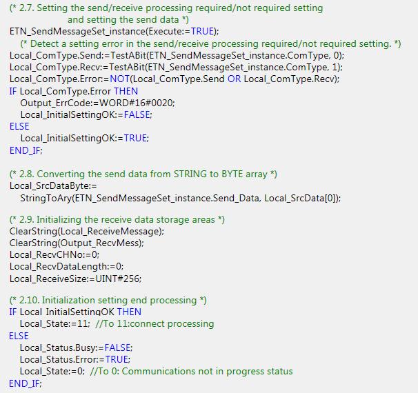
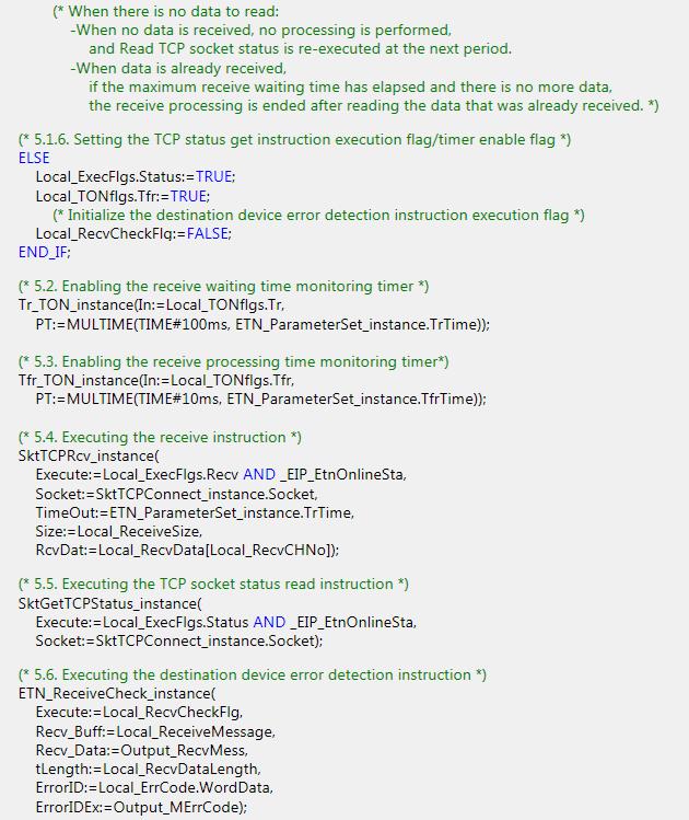
48 9.5. ST Program Functional Components of the Program This program is written in the ST language. The functional components are as follows. Major classification Minor classification Description 1. Communications processing 2. Initialization processing 3. Connect processing 1.1. Starting communications processing 1.2. Clearing the communications processing status flags 1.3 Communications processing in progress status 2.1. Initializing the timer 2.2. Initializing the instructions 2.3. Initializing the instruction execution flags 2.4. Initializing the timer enable flags 2.5. Initializing the error code storage areas 2.6. Setting each processing monitoring time and Ethernet communications parameters 2.7. Setting the send/receive processing required/not required setting and send data 2.8. Converting send data from a string to a BYTE array 2.9. Initializing the receive data storage areas Initialization setting end processing 3.1. Determining the connect processing status and setting the execution flag 3.2. Enabling the connect instruction monitoring timer 3.3. Executing the connect instruction 4. Send processing 4.1. Determining the send processing status and setting the execution flag 4.2. Enabling the send instruction monitoring timer 4.3. Executing the send instruction 5. Receive processing 5.1 Determining the receive processing status and setting the execution flag 5.2 Enabling the receive waiting time monitoring timer 5.3 Enabling the receive instruction monitoring timer 5.4 Executing the receive instruction 5.5 Executing the TCP socket status read processing 5.6 Executing the destination device error detection instruction The communications processing is started. The Ethernet parameters are set and the error code storage areas are initialized. The send/receive required/not required setting, send data and receive data are set. The connect processing is performed. The processing is performed unconditionally after starting the communications processing and executing the initialization setting. The processing is performed when the send processing required/not required setting is set to Required and the connect processing ends normally. The processing is performed when the receive processing required/not required setting is set to Required and the send processing ends normally. If multiple receive data arrive, the receive processing is repeated. The receive data is stored and checked. 45
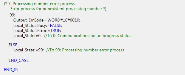
49 Major classification Minor classification Description 6. Close processing 6.1. Determining the close processing status and setting the execution flag 6.2. Enabling the close instruction monitoring timer 6.3. Executing the close instruction 6.4. Executing the TCP socket status read processing 7. Processing number error process The close processing is performed. The processing is performed in the following cases. When the receive processing required/not required setting is set to Not required and the send processing ends normally When the receive processing ends normally When any of the connect processing, send processing or receive processing ends in error 7. Processing number error process The error process is performed when a non-existent processing number was detected. 46
 are used to perform the communications settings, send data (command data) setting and receive data (response data) check that must")
50 Program List This section shows the details on the program. The function blocks (ParameterSet, SendMessageSet, and ReceiveCheck) are used to perform the communications settings, send data (command data) setting and receive data (response data) check that must be changed according to the destination device. For information on how to change these values, refer to Detailed Description of Function Blocks. Program: Program0 (General-purpose Ethernet communications Connection check program) 1. Communications processing 47

51 2. Initialization processing 48
52 49

53 3. Connect processing 50

54 4. Send processing 51

55 5. Receive processing 52
56 53

57 6. Close processing 54

58 7. Processing number error process 55
59 Detailed Description of Function Blocks The user-defined function blocks are shown below. The code which you need to edit according to the destination device is indicated by the red frames on the function blocks below. ParameterSet function block (General-purpose Ethernet communications parameter setting) Instruction Meaning ST expression ParameterSet General-purpose Ethernet Communications parameter setting ETN_ParameterSet_instance( Execute, TopenTime, TfsTime, TrTime, TfrTime, TcloseTime, SrcPort, DstIPAddr, DstPort); [Internal variable] None [Input/Output] Name I/O Data type Description Execute Input BOOL Execution flag: The function block is executed when this variable changes to TRUE and it is stopped when this variable changes to FALSE. TopenTime Output UINT Connect processing monitoring time: This variable sets the monitoring time of the connect processing in increments of 10 ms. TfsTime Output UINT Send processing monitoring time: This variable sets the monitoring time of the send processing in increments of 10 ms. TrTime Output UINT Receive wait monitoring time: This variable sets the waiting time for the receive data in increments of 100 ms. TfrTime Output UINT Receive processing monitoring time: This variable sets the monitoring time of the receive processing in increments of 10 ms. TcloseTime Output UINT Close processing monitoring time: This variable sets the monitoring time of the close processing in increments of 10 ms. SrcPort Output UINT Local port number: This variable sets the local port number. DstIPAddr Output STRING [256] Destination IP address: This variable sets the destination IP address. DstPort Output UINT Destination port number: This variable sets the destination port number. Busy Output BOOL Busy Done Output BOOL Normal end Not used Error Output BOOL Error end (Not used in this program.) ErrorID Output WORD Error code ErrorIDEx Output DWORD Expansion error code [External variable] None 56
![[Program]](/docs-images/96/127250241/images/60-0.jpg "57")
60 [Program] 57
61 SendMessageSet function block (General-purpose Ethernet communications send data setting) Instruction Meaning ST expression SendMessageSet General-purpose Ethernet communications send data setting ETN_SendMessageSet_instance( Execute, Send_Data, ComType); [Internal variables] Name Data type Description Send_Header STRING[5] Send header: Header of the send message Send_Addr STRING[5] Destination device address: Address of the destination device Send_Command STRING[256] Destination device command: Command sent to the destination device Send_Check STRING[5] Send check code: Check code of the send message Send_Terminate STRING[5] Send terminator: Terminator of the send message [Input/Output] Name I/O Data type Description Execute Input BOOL Execution flag: The function block is executed when this variable changes to TRUE and it is stopped when this variable changes to FALSE. Send_Data Output STRING[256] Send data: This variable sets a command that is sent to the destination device. ComType Output BYTE Send/Receive type: This variable sets whether send/receive processing are required. 1:Send only, 2: Receive only, 3: Send and receive Busy Output BOOL Busy Done Output BOOL Normal end Not used Error Output BOOL Error end (Not used in this project.) ErrorID Output WORD Error code ErrorIDEx Output DWORD Expansion error code [Internal variable] None 58
![[Program]](/docs-images/96/127250241/images/62-0.jpg "59")
62 [Program] 59
63 ReceiveCheck function block (General-purpose Ethernet communications receive processing) Instruction Meaning ST expression ETN_ReceiveCheck_instance( Execute, ReceiveCheck General-purpose Ethernet Recv_Data, Recv_Buff, Communications Error, receive processing ErrorID, ErrorIDEx); [Internal variables] Name Data type Description Receive_Check STRING[5] FCS receive value: FCS receive result of the receive data Calc_Check STRING[5] FCS calculation value: FCS calculation result of the receive data [Input/Output] Name I/O Data type Description Execution flag: The function block is executed when this Execute Input BOOL variable changes to TRUE and it is stopped when this variable changes to FALSE. tlength Input UINT Receive data length: The byte length of the receive data Recv_Data In-out STRING[256] Receive data storage area: An area that stores the receive data after detection Recv_Buff In-out STRING[256] Receive buffer: An area that temporarily stores the receive data that is used for detection. ErrorID In-out WORD Error code: This variable stores 16#1000 for a destination device error and 16#2000 for an FCS error. ErrorIDEx In-out DWORD Expansion error code: This variable stores the FCS determination result or destination device error code. Busy Output BOOL Busy Not used Done Output BOOL Normal end (Not used in this program.) Error Output BOOL Error end: TRUE when an error occurs. [External variable] None 60
![[Program]](/docs-images/96/127250241/images/64-0.jpg "61")
64 [Program] 61
65 9.6. Timing Charts The timing charts of this program are shown below. Start & End processing Input_Start Input_Start Local_Status.Busy Local_Status.Busy Connection processing Connection processing Send processing Send processing Receive processing Receive processing Close processing Close processing Local_ErrCode.WordData 16#0000 Output_SktCmdsErrorID 16#0000 Output_SktCloseErrorID 16#0000 Local_ErrCode.BoolData[15] Output_ErrCode 16#0000 Local_Status.Done Local_Status.Error (Normal end) Local_ErrCode.WordData 16# #**** Output_SktCmdsErrorID 16# #**** Output_SktCloseErrorID 16# #**** Local_ErrCode.BoolData[15] Outputl_ErrCode 16#0000 Local_Status.Done Local_Status.Error (Error end) 16#**** If Input_Start changes from TRUE to FALSE during execution, a normal end or an error end is output for one period after the processing is completed as shown below. Input_Start Input_Start Local_Status.Busy Local_Status.Busy Local_Status.Done Local_Status.Done Local_Status.Error Output for one period Local_Status.Error Output for one period (Normal end) (Error end) 62
66 Connect processing Input_Start Input_Start SktTCPConnect _instance.execute SktTCPConnect _instance.execute Topen_TON _instance.q Topen_TON _instance.q SktTCPConnect _instance.busy SktTCPConnect _instance.busy SktTCPConnect _instance.done SktTCPConnect _instance.done SktTCPConnect _instance.error SktTCPConnect _instance.error Local_ErrCode.BoolData[2] Local_ErrCode.WordData 16#0000 Local_ErrCode.BoolData[2] Local_ErrCode.WordData 16# #0004 Output_sktCmds ErrorID 16#0000 Output_SktCmds ErrorID 16# #**** SktTCPSend _instance.execute (Normal end) SktClose _instance.execute (Error end) Input_Start SktTCPConnect _instance.execute Topen_TON _instance.q Monitoring time elapsed SktTCPConnect _instance.busy SktTCPConnect _instance SktTCPConnect _instance.error Local_ErrCode.BoolData[10] Local_ErrCode.WordData Output_SktCmds ErrorID SktClose _instance.execute 16# # # #FFFF (Timeout) 63
67 Send processing SktTCPConnect _instance.done SktTCPSend _instance.execute Tfs_TON _instance.q SktTCPSend _instance.busy SktTCPSend _instance.done SktTCPSend _instance.error Local_ErrCode.BoolData[0] Local_ErrCode.WordData Output_sktCmds ErrorID SktGetTCPStatus _instance.execute 16# #0000 (Normal end) SktTCPConnect _instance.done SktTCPSend _instance.execute Tfs_TON _instance.q SktTCPSend _instance.busy SktTCPSend _instance.done SktTCPSend _instance.error Local_ErrCode.BoolData[0] Local_ErrCode.WordData Output_sktCmds ErrorID SktClose _instance.execute 16# # # #**** (Error end) SktTCPConnect _instance.done SktTCPSend _instance.execute Tfs_TON _instance.q Monitoring time elapsed SktTCPSend _instance.busy SktTCPSend _instance.done SktTCPSend _instance.error Local_ErrCode.BoolData[8] Local_ErrCode.WordData Output_sktCmds ErrorID SktClose _instance.execute 16# # # #FFFF (Timeout) 64
68 Receive processing SktTCPSend _instance.done SktGetTCPStatus _instance.execute SktGetTCPStatus _instance.datrcvflag Receive data exists. Receive data exists. SktTCPSend _instance.done SktGetTCPStatus _instance.execute SktGetTCPStatus _instance.datrcvflag No receive data SktTCPRcv _instance.execute Tr_TON_instance.Q SktTCPRcv _instance.execute Tr_TON_instance.Q Receive waiting time SktTCPRcv _instance.busy SktTCPRcv _instance.busy SktTCPRcv _instance.done SktTCPRcv _instance.error Local_ErrCode.BoolData[1] Local_ErrCode.WordData Output_sktCmds ErrorID 16# #0000 (Repeat) SktTCPRcv _instance.done SktTCPRcv _instance.error Local_ErrCode.BoolData[12] Local_ErrCode.WordData Output_sktCmds ErrorID SktClose _instance.execute No destination device error 16# #0000 (Normal end) SktTCPSend _instance.done SktTCPSend _instance.done SktGetTCPStatus _instance.execute SktGetTCPStatus _instance.execute SktGetTCPStatus _instance.datrcvflag No receive data SktGetTCPStatus _instance.datrcvflag Receive data exists. SktTCPRcv _instance.execute Tr_TON_instance.Q Receive waiting time SktTCPRcv _instance.execute Tr_TON_instance.Q SktTCPRcv _instance.busy SktTCPRcv _instance.done SktTCPRcv _instance.error Local_ErrCode.BoolData[12] Local_ErrCode.WordData Output_sktCmds ErrorID SktClose _instance.execute Destination device error occurred. 16# # #0000 (Destination device error) SktTCPRcv _instance.busy SktTCPRcv _instance.done SktTCPRcv _instance.error Local_ErrCode.BoolData[1] Local_ErrCode.WordData Output_sktCmds ErrorID SktClose _instance.execute 16# # # #**** (Error end) 65
69 SktTCPSend _instance.done SktGetTCPStatus _ins tance.execute SktGetTCPStatus _instance.datrcvflag SktTCPRcv _instance.execute Tfr_TON _instance.q SktTCPRcv _instance.busy Receive data exists. Monitoring time elapsed. SktTCPRcv _instance.done SktTCPRcv _instance.error Local_ErrCode.BoolData[9] Local_ErrCode WordData 16# #0200 Output_sktCmds ErrorID 16#0000 SktClose. _instance.execute 16#FFFF (Timeout) 66
70 Close processing Tr_TON_instance.Q etc SktClose _instance.execute Tclose_TON _instance.q SktClose _instance.busy Tr_TON_instance.Q etc SktClose _instance.execute Tclose_TON _instance.q SktClose _instance.busy SktClose _instance.done SktClose _instance.error SktGetTCPStatus _instance.execute SktClose _instance.done SktClose _instance.error SktGetTCPStatus _instance.execute SktGetTCPStatus _instance.tcpsta Output_skTclose ErrorID Local_ErrCode.BoolData[3] Local_ErrCode.WordData _XXXX 16# #0000 _CLOSED SktGetTCPStatus _instance.tcpsta Output_Sktclose ErrorID Local_ErrCode.BoolData[3] Local_ErrCode.WordData _XXXX 16# #**** 16#**** 16#0008 To End processing To End processing (Normal end) (Error end) Tr_TON_instance.Q etc SktClose _instance.execute Tclose_TON _instance.q SktClose _instance.busy SktClose _instance.done SktClose _instance.error SktGetTCPStatus _instance.execute SktGetTCPStatus _instance.tcpsta Output_SktClose ErrorID Local_ErrCode.BoolData[11] Local_ErrCode.WordData _XXXX Monitoring time elapsed. _CLOSED 16# #FFFF 16#**** 16#0800 To End processing (Timeout) 67
71 9.7. Error Process Error Code List The error codes for this program are shown below. Error flag (Error end/timeout) [Output_ErrCode] If the connect processing, send processing, receive processing or close processing ends in error or timed out, the error flag will be set in the Output_ErrCode variable. Error flag 16#0000 Normal end 16#0001 The send processing ended in error. 16#0002 The receive processing ended in error. 16#0004 The connect processing ended in error. 16#0008 The close processing ended in error. Description 16#0100 The send processing did not end in time. 16#0200 The receive processing did not end in time. (Including when an arrival of the response cannot be checked.) 16#0400 The connect processing did not end in time. 16#0800 The close processing did not end in time. 16#0010 Processing number error 16#0020 Send/Receive required/not required detection error 16#1000 Destination device error 16#2000 Destination device FCS (checksum) error 16#8000 Error occurrence *The error flags detected for each processing are added and the addition result is stored in the error flag. (Example) The connect TCP socket instruction error end + Close status check timeout WORD#16#8000 (Error occurrence) +WORD#16#0001 (TCP socket connect instruction ended in error) +WORD#16#0100 (Close status check timeout) Output_ErrorID: WORD#16#
72 Error codes [Output_SktCmdsErrorID], [Output_SkTcloseErrorID] If an error occurs in the connect processing, send processing or receive processing, the error code is stored in the Output_SktCmdsErrorID variable and then the close processing is performed. If an error occurs in the close processing, the error code is stored in the Output_SkTcloseErrorID variable and the processing ends. The main error codes are shown below. Error code Description 16#0000 Normal end 16#0400 An input parameter for an instruction exceeded the valid range for an input variable. 16#0407 The results of instruction processing exceeded the data area range of the output parameter. 16#2000 An instruction was executed when there was a setting error in the local IP address. Address resolution failed for a destination node with the domain name that was specified in 16#2002 the instruction. The status was not suitable for execution of the instruction. SktTCPConnect Instruction The TCP port that is specified with the SrcTcpPort input variable is already connected. The destination node that is specified with DstAdr input variable does not exist. The destination node that is specified with DstAdr and DstTcpPort input variables are not waiting for a connection. 16#2003 SktTCPRcv Instruction The specified socket is receiving data. The specified socket is not connected. SktTCPSend Instruction The specified socket is sending data. The specified socket is not connected. 16#2006 A timeout occurred for a socket service instruction. 16#2007 The handle that is specified for the socket service instruction is not correct. The maximum resources that you can use for socket service instructions at the same time 16#2008 was exceeded. 16#FFFF Processing ends without completing the executing of an instruction. Additional Information For details, refer to A-1 Error Code Details and A-2 Error Code Descriptions under Appendices in the NJ-series Instructions Reference Manual (Cat. No. W502). Additional Information For details on socket service errors and troubleshooting, refer to 9-7 Precautions in Using Socket Services of Chapter 9 Socket Service in the NJ-series CPU Unit Built-in EtherNet/IP Port User's Manual (Cat. No. W506). 69
73 TCP connection status error [Output_EtnTcpSta] If the TCP connection status does not enter the normal status (_CLOSED) in time after the close processing, a TCP connection status code is set in the Output_EtnTcpSta variable. (If the close processing ends in error, check this also.) Error code enumerator _econnection_state _CLOSED _LISTEN _SYN SENT _SYN RECEIVED _ESTABLISHED _CLOSE WAIT _FIN WAIT1 _CLOSING _LAST ACK _FIN WAIT2 _TIME WAIT Description Connection closed. (Normal status) Waiting for connection SYN sent in active status. SYN sent and received. Already established. FIN received and waiting for completion. Completed and FIN sent. Completed and exchanged FIN. Awaiting ACK. FIN received and completed. Awaiting ACK. Completed and ACK received. Awaiting FIN. After closing, pauses twice the maximum segment life (2MSL). 70

74 Destination device error code The destination device error code is stored in the Output_MErrCode variable. When 16#2000 is stored in Output_ErrCode, the FCS value of the data received from the destination device is stored in Output_MErrCode. When 16#1000 is stored in Output_ErrCode, the error number is stored in Output_MErrCode as the destination device error code. Bit #0000 Response code 16#**:Main 16#**:Sub Note1: 'x' character in response code means one character in the list of 0 to 9 or A to F. 71
Connection Guide (RS-232C) OMRON Corporation
 OMRON Corporation") Machine Automation Controller NJ-series General-purpose Serial Connection Guide (RS-232C) OMRON Corporation V750 series RFID System P544-E1-01 About Intellectual Property Right and Trademarks Microsoft
Machine Automation Controller NJ-series General-purpose Serial Connection Guide (RS-232C) OMRON Corporation V750 series RFID System P544-E1-01 About Intellectual Property Right and Trademarks Microsoft
Connection Guide (RS-232C) OMRON Corporation
 OMRON Corporation") Machine Automation Controller NJ-series General-purpose Serial Connection Guide (RS-232C) OMRON Corporation ZW-series Displacement Sensor P559-E1-01 About Intellectual Property Right and Trademarks Microsoft
Machine Automation Controller NJ-series General-purpose Serial Connection Guide (RS-232C) OMRON Corporation ZW-series Displacement Sensor P559-E1-01 About Intellectual Property Right and Trademarks Microsoft
Connection Guide (RS-232C) OMRON Corporation
 OMRON Corporation") Machine Automation Controller NJ-series General-purpose Serial Connection Guide (RS-232C) OMRON Corporation Ultra Small Multi-code Reader (V400-R2 Series) P567-E1-01 About Intellectual Property Rights
Machine Automation Controller NJ-series General-purpose Serial Connection Guide (RS-232C) OMRON Corporation Ultra Small Multi-code Reader (V400-R2 Series) P567-E1-01 About Intellectual Property Rights
Machine Automation Controller NJ-series. EtherNet/IP TM. Connection Guide. OMRON Corporation. CJ2-series Controller P568-E1-01
 Machine Automation Controller NJ-series EtherNet/IP TM Connection Guide OMRON Corporation CJ2-series Controller P568-E1-01 About Intellectual Property Rights and Trademarks Microsoft product screen shots
Machine Automation Controller NJ-series. EtherCAT. Connection Guide. OMRON Corporation. Displacement Sensor(Confocal Fiber Type) (ZW-CE1) P538-E1-01
 (ZW-CE1) P538-E1-01") Machine Automation Controller NJ-series EtherCAT Connection Guide OMRON Corporation Displacement Sensor(Confocal Fiber Type) (ZW-CE1) P538-E1-01 About Intellectual Property Right and Trademarks Microsoft
Machine Automation Controller NJ-series EtherCAT Connection Guide OMRON Corporation Displacement Sensor(Confocal Fiber Type) (ZW-CE1) P538-E1-01 About Intellectual Property Right and Trademarks Microsoft
Connection Guide (RS-232C)
") Machine Automation Controller NJ-series General-purpose Seriarl Connection Guide (RS-232C) OMRON Corporation G9SP Safety Controller P545-E1-01 About Intellectual Property Rights and Trademarks Microsoft
Machine Automation Controller NJ-series General-purpose Seriarl Connection Guide (RS-232C) OMRON Corporation G9SP Safety Controller P545-E1-01 About Intellectual Property Rights and Trademarks Microsoft
Machine Automation Controller NJ-series. EtherCAT. Connection Guide. OMRON Corporation. GX-series Digital I/O Terminal P517-E1-01
 Machine Automation Controller NJ-series EtherCAT Connection Guide OMRON Corporation GX-series Digital I/O Terminal P517-E1-01 Table of Contents 1. Related Manuals... 1 2. Terms and Definition... 2 3. Remarks...
Machine Automation Controller NJ-series. EtherCAT. Connection Guide. OMRON Corporation. Digital Sensor Communication Unit (E3NW-ECT) P563-E1-01
 P563-E1-01") Machine Automation Controller NJ-series EtherCAT Connection Guide OMRON Corporation Digital Sensor Communication Unit (E3NW-ECT) P563-E1-01 About Intellectual Property Right and Trademarks Microsoft product
Machine Automation Controller NJ-series EtherCAT Connection Guide OMRON Corporation Digital Sensor Communication Unit (E3NW-ECT) P563-E1-01 About Intellectual Property Right and Trademarks Microsoft product
Connection Guide HMS Industrial Networks
 Machine Automation Controller NJ-series EtherCAT(R) Connection Guide HMS Industrial Networks Anybus Communicator P560-E1-02 About Intellectual Property Rights and Trademarks Microsoft product screen shots
PHOENIX CONTACT GmbH & Co. KG
 Machine Automation Controller NJ-series EtherCAT(R) Connection Guide PHOENIX CONTACT GmbH & Co. KG I/O SYSTEM (Axioline F Series) P621-E1-01 About Intellectual Property Rights and Trademarks Microsoft
DELTA ELECTRICS, INC.
 Machine Automation Controller NJ-series EtherCAT(R) Connection Guide DELTA ELECTRICS, INC. EtherCAT Slave Remote module (R1-EC Series) P655-E1-01 About Intellectual Property Rights and Trademarks Microsoft
Machine Automation Controller NJ-series. EtherCAT(R) Connection Guide. OMRON Corporation. Displacement Sensor (ZW-7000 Series) P651-E1-01
 Connection Guide. OMRON Corporation. Displacement Sensor (ZW-7000 Series) P651-E1-01") Machine Automation Controller NJ-series EtherCAT(R) Connection Guide OMRON Corporation Displacement Sensor (ZW-7000 Series) P651-E1-01 About Intellectual Property Rights and Trademarks Microsoft product
Machine Automation Controller NJ-series EtherCAT(R) Connection Guide OMRON Corporation Displacement Sensor (ZW-7000 Series) P651-E1-01 About Intellectual Property Rights and Trademarks Microsoft product
Machine Automation Controller NJ-series. EtherCAT. Connection Guide. OMRON Corporation. E3X-ECT Sensor Communication Unit (EtherCAT Slave) P529-E1-01
 P529-E1-01") Machine Automation Controller NJ-series EtherCAT Connection Guide OMRON Corporation E3X-ECT Sensor Communication Unit (EtherCAT Slave) P529-E1-01 Table of Contents 1. Related Manuals... 1 2. Terms and
Machine Automation Controller NJ-series EtherCAT Connection Guide OMRON Corporation E3X-ECT Sensor Communication Unit (EtherCAT Slave) P529-E1-01 Table of Contents 1. Related Manuals... 1 2. Terms and
Machine Automation Controller NJ-series. EtherNet/IP TM. Connection Guide. OMRON Corporation. Displacement Sensor (ZW-7000 series) P653-E1-01
 P653-E1-01") Machine Automation Controller NJ-series EtherNet/IP TM Connection Guide OMRON Corporation Displacement Sensor (ZW-7000 series) P653-E1-01 About Intellectual Property Rights and Trademarks Microsoft product
Machine Automation Controller NJ-series EtherNet/IP TM Connection Guide OMRON Corporation Displacement Sensor (ZW-7000 series) P653-E1-01 About Intellectual Property Rights and Trademarks Microsoft product
Machine Automation Controller NJ-series. EtherCAT(R) Connection Guide. Balluff GmbH. Network Interface (BNI ECT-508) P673-E1-01
 Connection Guide. Balluff GmbH. Network Interface (BNI ECT-508) P673-E1-01") Machine Automation Controller NJ-series EtherCAT(R) Connection Guide Balluff GmbH Network Interface (BNI ECT-508) P673-E1-01 About Intellectual Property Rights and Trademarks Microsoft product screen shots
Machine Automation Controller NJ-series EtherCAT(R) Connection Guide Balluff GmbH Network Interface (BNI ECT-508) P673-E1-01 About Intellectual Property Rights and Trademarks Microsoft product screen shots
CJ Series General-purpose Serial Connection Guide OMRON Corporation V500-R2 Series Fixed Laser-Type Barcode Reader
 CJ Series General-purpose Serial Connection Guide OMRON Corporation V500-R2 Series Fixed Laser-Type Barcode Reader P564-E1-01 About Intellectual Property Rights and Trademarks Microsoft product screen
Connection Guide FANUC CORPORATION
 Machine Automation Controller NJ-series EtherCAT(R) Connection Guide FANUC CORPORATION R-30iB Robot Controller P605-E1-01 About Intellectual Property Rights and Trademarks Microsoft product screen shots
OMRON Corporation. IO-Link Connection Guide (EtherCAT(R) Host Communications) Machine Automation Controller NJ-series
 Host Communications) Machine Automation Controller NJ-series") Machine Automation Controller NJ-series IO-Link Connection Guide (EtherCAT(R) Host Communications) OMRON Corporation Proximity Sensor (E2E-series IO-Link) [IO-Link Master Unit] OMRON Corporation NX-series
Machine Automation Controller NJ-series IO-Link Connection Guide (EtherCAT(R) Host Communications) OMRON Corporation Proximity Sensor (E2E-series IO-Link) [IO-Link Master Unit] OMRON Corporation NX-series
Omron Adept Technologies,Inc.
 Machine Automation Controller NJ-series EtherNet/IP TM Connection Guide Omron Adept Technologies,Inc. Adept Robot of eplc P649-E1-01 About Intellectual Property Rights and Trademarks Microsoft product
Connection Guide. SMC Corporation. EtherCAT(R) Machine Automation Controller NJ-series
 Machine Automation Controller NJ-series") Machine Automation Controller NJ-series EtherCAT(R) Connection Guide SMC Corporation EtherCAT Direct input type Step Motor Controller (Servo 24VDC) (JXCE1) P677-E1-01 About Intellectual Property Rights
Machine Automation Controller NJ-series EtherCAT(R) Connection Guide SMC Corporation EtherCAT Direct input type Step Motor Controller (Servo 24VDC) (JXCE1) P677-E1-01 About Intellectual Property Rights
EtherCAT(R) Connection Guide IAI Corporation
 Connection Guide IAI Corporation") Machine Automation Controller NJ-series EtherCAT(R) Connection Guide IAI Corporation X-SEL Controller (XSEL-R/S/RX/SX/RXD/SXD) P549-E1-01 About Intellectual Property Rights and Trademarks Microsoft product
Machine Automation Controller NJ-series EtherCAT(R) Connection Guide IAI Corporation X-SEL Controller (XSEL-R/S/RX/SX/RXD/SXD) P549-E1-01 About Intellectual Property Rights and Trademarks Microsoft product
OMRON Corporation. IO-Link Connection Guide (EtherCAT(R) Host Communications) Machine Automation Controller NJ-series
 Host Communications) Machine Automation Controller NJ-series") Machine Automation Controller NJ-series IO-Link Connection Guide (EtherCAT(R) Host Communications) OMRON Corporation Photoelectric Sensor (E3Z-series IO-Link) [IO-Link Master Unit] OMRON Corporation GX-series
Machine Automation Controller NJ-series IO-Link Connection Guide (EtherCAT(R) Host Communications) OMRON Corporation Photoelectric Sensor (E3Z-series IO-Link) [IO-Link Master Unit] OMRON Corporation GX-series
FESTO K.K. IO-Link Connection Guide (EtherCAT(R) Host Communications) Machine Automation Controller NJ-series
 Host Communications) Machine Automation Controller NJ-series") Machine Automation Controller NJ-series IO-Link Connection Guide (EtherCAT(R) Host Communications) FESTO K.K. Proportional pressure regulator valve (VPPM series) [IO-Link Master Unit] OMRON Corporation
Machine Automation Controller NJ-series IO-Link Connection Guide (EtherCAT(R) Host Communications) FESTO K.K. Proportional pressure regulator valve (VPPM series) [IO-Link Master Unit] OMRON Corporation
CJ Series EtherNet/IP TM Connection Guide. OMRON Corporation NX-series EtherNet/IP Coupler Unit P656-E1-01
 CJ Series EtherNet/IP TM Connection Guide OMRON Corporation NX-series EtherNet/IP Coupler Unit P656-E1-01 About Intellectual Property Rights and Trademarks Microsoft product screen shots reprinted with
MARS TOHKEN SOLUTION CO.LTD. Fixed Mount 1D/2D Image Reader (TFIR-31LAN Series)
") No.FST-ZTG140008A CJ Series General-purpose Ethernet Connection Guide MARS TOHKEN SOLUTION CO.LTD. Fixed Mount 1D/2D Image Reader (TFIR-31LAN Series) P606-E1-01 About Intellectual Property Rights and Trademarks
No.FST-ZTG140008A CJ Series General-purpose Ethernet Connection Guide MARS TOHKEN SOLUTION CO.LTD. Fixed Mount 1D/2D Image Reader (TFIR-31LAN Series) P606-E1-01 About Intellectual Property Rights and Trademarks
CJ Series EtherNet/IP TM Connection Guide. OMRON Corporation RFID Reader/Writer (V680S-series) P626-E1-01
 P626-E1-01") CJ Series EtherNet/IP TM Connection Guide OMRON Corporation RFID Reader/Writer (V680S-series) P626-E1-01 About Intellectual Property Rights and Trademarks Microsoft product screen shots reprinted with
CJ Series EtherNet/IP TM Connection Guide OMRON Corporation RFID Reader/Writer (V680S-series) P626-E1-01 About Intellectual Property Rights and Trademarks Microsoft product screen shots reprinted with
Piab AB. IO-Link Connection Guide (EtherCAT(R) Host Communications) Machine Automation Controller NJ-series. Vacuum Ejector (picompact 23 IO-Link)
 Host Communications) Machine Automation Controller NJ-series. Vacuum Ejector (picompact 23 IO-Link)") Machine Automation Controller NJ-series IO-Link Connection Guide (EtherCAT(R) Host Communications) Piab AB Vacuum Ejector (picompact 23 IO-Link) [IO-Link Master Unit] OMRON Corporation NX-series IO-Link
Machine Automation Controller NJ-series IO-Link Connection Guide (EtherCAT(R) Host Communications) Piab AB Vacuum Ejector (picompact 23 IO-Link) [IO-Link Master Unit] OMRON Corporation NX-series IO-Link
CJ Series EtherNet/IP TM Connection Guide. ABB Ltd. IRC5 Robot Controller P572-E1-01
 CJ Series EtherNet/IP TM Connection Guide ABB Ltd. IRC5 Robot Controller P572-E1-01 About Intellectual Property Rights and Trademarks Microsoft product screen shots reprinted with permission from Microsoft
CJ Series IO-Link Connection Guide (EtherNet/IP TM Host Communications) OMRON Corporation Proximity Sensor (E2E-series IO-Link)
 OMRON Corporation Proximity Sensor (E2E-series IO-Link)") CJ Series IO-Link Connection Guide (EtherNet/IP TM Host Communications) OMRON Corporation Proximity Sensor (E2E-series IO-Link) [IO-Link Master Unit] OMRON Corporation NX-series IO-Link Master Unit (NX-ILM[][][])
CJ Series IO-Link Connection Guide (EtherNet/IP TM Host Communications) OMRON Corporation Proximity Sensor (E2E-series IO-Link) [IO-Link Master Unit] OMRON Corporation NX-series IO-Link Master Unit (NX-ILM[][][])
ORIENTAL MOTOR CO., LTD.
 Machine Automation Controller NJ-series EtherCAT(R) Connection Guide ORIENTAL MOTOR CO., LTD. Network Converter NETC01-ECT -Closed Loop Stepping Motor and Driver Package αstep High-Efficiency AR Series
Machine Automation Controller NJ-series. EtherNet/IP TM. Connection Guide. OMRON Corporation. FZ5-series Vision System P589-E1-01
 Machine Automation Controller NJ-series EtherNet/IP TM Connection Guide OMRON Corporation FZ5-series Vision System P589-E1-01 About Intellectual Property Rights and Trademarks Microsoft product screen
No.FST-ZTH130453A. CJ Series EtherCAT Connection Guide. OMRON Corporation. E3NW-ECT Digital Sensor Communication Unit P562-E1-01
 No.FST-ZTH130453A CJ Series EtherCAT Connection Guide OMRON Corporation E3NW-ECT Digital Sensor Communication Unit P562-E1-01 About Intellectual Property Right and Trademarks Microsoft product screen shots
CJ Series EtherNet/IP TM Connection Guide. Yamaha Motor Co., Ltd. Robot Controller (RCX340) P624-E1-01
 P624-E1-01") CJ Series EtherNet/IP TM Connection Guide Yamaha Motor Co., Ltd. Robot Controller (RCX340) P624-E1-01 About Intellectual Property Rights and Trademarks Microsoft product screen shots reprinted with permission
CJ Series EtherNet/IP TM Connection Guide Yamaha Motor Co., Ltd. Robot Controller (RCX340) P624-E1-01 About Intellectual Property Rights and Trademarks Microsoft product screen shots reprinted with permission
CJ Series EtherNet/IP TM Connection Guide. SMC Corporation Solenoid Valve (SI Unit EX600-SEN#) P657-E1-01
 P657-E1-01") CJ Series EtherNet/IP TM Connection Guide SMC Corporation Solenoid Valve (SI Unit EX600-SEN#) P657-E1-01 About Intellectual Property Rights and Trademarks Microsoft product screen shots reprinted with
CJ Series EtherNet/IP TM Connection Guide SMC Corporation Solenoid Valve (SI Unit EX600-SEN#) P657-E1-01 About Intellectual Property Rights and Trademarks Microsoft product screen shots reprinted with
Connection Guide (RS-232C)
") Programmable Controller CJ-series General-purpose Serial Connection Guide (RS-232C) MARS TOHKEN SOLUTION CO.LTD. Fixed Mount 2D Image Reader (MVF-300/500 Series) P679-E1-01 About Intellectual Property
Programmable Controller CJ-series General-purpose Serial Connection Guide (RS-232C) MARS TOHKEN SOLUTION CO.LTD. Fixed Mount 2D Image Reader (MVF-300/500 Series) P679-E1-01 About Intellectual Property
No. FST-ZTH13079B. Machine Automation Controller NJ-series. EtherCAT Connection Guide. Kollmorgen Corporation Servo Drive (AKD )
") No. FST-ZTH13079B Machine Automation Controller NJ-series EtherCAT Connection Guide Kollmorgen Corporation Servo Drive (AKD ) About Intellectual Property Rights and Trademarks Microsoft product screen
No. FST-ZTH13079B Machine Automation Controller NJ-series EtherCAT Connection Guide Kollmorgen Corporation Servo Drive (AKD ) About Intellectual Property Rights and Trademarks Microsoft product screen
CJ Series EtherNet/IP TM Connection Guide. OMRON Corporation Vision System (FZ5 Series) P588-E1-02
 P588-E1-02") CJ Series EtherNet/IP TM Connection Guide OMRON Corporation Vision System (FZ5 Series) P588-E1-02 About Intellectual Property Rights and Trademarks Microsoft product screen shots reprinted with permission
CJ Series EtherNet/IP TM Connection Guide OMRON Corporation Vision System (FZ5 Series) P588-E1-02 About Intellectual Property Rights and Trademarks Microsoft product screen shots reprinted with permission
Omron Adept Technologies,Inc.
 Machine Automation Controller NJ-series EtherNet/IP TM Connection Guide Omron Adept Technologies,Inc. Adept Robot of eplcio P650-E1-01 About Intellectual Property Rights and Trademarks Microsoft product
CJ Series General-purpose Serial Connection Guide (RS-232C) OMRON Corporation Displacement Sensor (ZW-7000 series)
 OMRON Corporation Displacement Sensor (ZW-7000 series)") CJ Series General-purpose Serial Connection Guide (RS-232C) OMRON Corporation Displacement Sensor (ZW-7000 series) P652-E1-01 About Intellectual Property Rights and Trademarks Microsoft product screen
CJ Series General-purpose Serial Connection Guide (RS-232C) OMRON Corporation Displacement Sensor (ZW-7000 series) P652-E1-01 About Intellectual Property Rights and Trademarks Microsoft product screen
CJ-series DeviceNet Connection Guide OMRON Corporation 3G3RX-V1 Series Inverter
 CJ-series DeviceNet Connection Guide OMRON Corporation 3G3RX-V1 Series Inverter P547-E1-01 About Intellectual Property Rights and Trademarks Microsoft product screen shots reprinted with permission from
Connection Guide IAI Corporation
 Machine Automation Controller NJ-series EtherCAT Connection Guide IAI Corporation Controller SCON-CA P585-E1-01 About Intellectual Property Rights and Trademarks Microsoft product screen shots reprinted
Machine Automation Controller NJ-series. EtherCAT(R) Connection Guide. IAI Corporation. ACON/ACON-CA/ PCON/PCON-CA/ DCON-CA Controller P584-E1-02
 Connection Guide. IAI Corporation. ACON/ACON-CA/ PCON/PCON-CA/ DCON-CA Controller P584-E1-02") Machine Automation Controller NJ-series EtherCAT(R) Connection Guide IAI Corporation ACON/ACON-CA/ PCON/PCON-CA/ DCON-CA Controller P584-E1-02 About Intellectual Property Rights and Trademarks Microsoft
Machine Automation Controller NJ-series EtherCAT(R) Connection Guide IAI Corporation ACON/ACON-CA/ PCON/PCON-CA/ DCON-CA Controller P584-E1-02 About Intellectual Property Rights and Trademarks Microsoft
Rockwell Automation ControlLogix 1756-L71 EtherNet/IP Connection Guide. OMRON Corporation. RFID System V680S. V680S RFID System. Cat. No.
 Rockwell Automation ControlLogix 1756-L71 EtherNet/IP Connection Guide OMRON Corporation RFID System V680S V680S RFID System Cat. No. P242I-E-02 About Intellectual Property Right and Trademarks Microsoft
MODEL : CT-E351ET Ethernet Interface function Manual. Ver.1.01
 MODEL : CT-E351ET Ethernet Interface function Manual Ver.1.01 Contents Contents... 2 Read before using... 3 1. Introduction... 4 1-1. Specifications... 4 1-2. Part Names and Functions... 5 1-3. LED Functions...
Configuring EtherCAT BIS V on Omron NJ PLC
 Configuring EtherCAT BIS V on Omron NJ PLC BIS00U9 Obtain the appropriate ESI files for the BIS00U9 either from the Balluff website or on the disk that is included with the processor. Copy them into the
Sysmac Studio Version 1
 Automation Software Sysmac Studio Version 1 Drive Functions Operation Manual SYSMAC-SE2 I589-E1-04 NOTE All rights reserved. No part of this publication may be reproduced, stored in a retrieval system,
Safety Network Controller NX-series Communication Control Unit User's Manual. Built-in Function NX-CSG. Communication Control Unit
 Safety Network Controller NX-series Communication Control Unit User's Manual Built-in Function NX-CSG Communication Control Unit NOTE (1) All rights reserved. No part of this publication may be reproduced,
Ethernet Interface Board MODEL : IF2-ET01 User s Manual. Ver.1.03
 Ethernet Interface Board MODEL : IF2-ET01 User s Manual Ver.1.03 Contents Contents... 2 Read before using... 3 Safety Instructions... 4 1. Introduction... 5 1-1. Specifications... 5 1-2. Part Names and
Machine Automation Controller NX-series CPU Unit User's Manual. FINS Function NX NX NX NX NX NX W596I-E3-01
 Machine Automation Controller NX-series CPU Unit User's Manual FINS Function NX701-1720 NX701-1620 NX102-12 NX102-11 NX102-10 NX102-90 W596I-E3-01 NOTE (1) All rights reserved. No part of this publication
CPU Unit Motion Control
 Machine Automation Controller NJ-series CPU Unit Motion Control User s Manual NJ501-1300 NJ501-1400 NJ501-1500 CPU Unit W507-E1-01 OMRON, 2011 All rights reserved. No part of this publication may be reproduced,
Machine Automation Controller NJ/NX-series Database Connection CPU Units. User s Manual NX NX NJ NJ CPU Unit W527I-E3-10
 Machine Automation Controller NJ/NX-series Database Connection CPU Units User s Manual NX701-20 NX102-20 NJ501-20 NJ101-20 CPU Unit W527I-E3-10 NOTE All rights reserved. No part of this publication may
Operating Instructions
 KX-HGW500 WIRELESS LAN1 LAN2 LAN3 LAN4 INTERNET POWER Network Camera Management System Operating Instructions Model No. KX-HGW600 Please read this manual before using and save this manual for your future
Service Portal User Guide
 FUJITSU Cloud Service K5 IaaS Service Portal User Guide Version 1.4 FUJITSU LIMITED All Rights Reserved, Copyright FUJITSU LIMITED 2015-2016 K5IA-DC-M-005-001E Preface Purpose of This Manual This manual
B Programmable Terminal NB Series. Practice Guide. Sysmac Studio Variable Table Import NB3Q-TW01B NB5Q-TW01B NB7W-TW01B NB10W-TW01B
 B-181206 Programmable Terminal NB Series Practice Guide Sysmac Studio Variable Table Import NB3Q-TW01B NB5Q-TW01B NB7W-TW01B NB10W-TW01B Introduction This guide provides reference information when designing
Practices Guide. Programmable Terminal NB-series. - Disable/Enable communication with PLCs in Run -time
 Programmable Terminal NB-series Practices Guide - Disable/Enable communication with PLCs in Run -time - Print Screen image + Display Component information - Project file management NB3Q-TW01B NB5Q-TW01B
EtherNet/IP Monitor Tool Operation Manual
 EtherNet/IP Monitor Tool Operation Manual Introduction This manual documents the operating procedures of the EtherNet/IP Monitor Tool. It does not contain other information, such as precautions. In actual
Automation Software. Sysmac Studio. Project Version Control Function Operation Manual SYSMAC-SE2 SYSMAC-TA4 L W589-E1-01
 Automation Software Sysmac Studio Project Version Control Function Operation Manual SYSMAC-SE2 SYSMAC-TA4 L W589-E1-01 NOTE All rights reserved. No part of this publication may be reproduced, stored in
Switch-mode Power Supplies
 1 Product Overview 2 IP Address Setting and Resetting Switch-mode Power Supplies Communications Manual S8VK-X 3 Monitoring and Setting with the EtherNet/IP 4 Monitoring and Setting with the Modbus TCP
Network Guide NPD EN
 NPD5659-00 EN Copyright and Trademarks No part of this publication may be reproduced, stored in a retrieval system, or transmitted in any form or by any means, mechanical, photocopying, recording, or otherwise,
NCOM SERIAL DEVICE SERVER 1XX SERIES USER S MANUAL
 NCOM SERIAL DEVICE SERVER 1XX SERIES USER S MANUAL 2017-07-07 Edition Titan Electronics Inc. Web: www.titan.tw Contents 1. INTRODUCTION... 4 1.1 Key Features... 5 1.2 Specifications... 6 2. PANEL LAYOUT
User Manual. Network Interface Card (NC-6)
") User Manual Network Interface Card (NC-6) Contents 1 Welcome 1.1 Trademark Acknowledgements...1-2 1.2 About PageScope Light...1-2 2 Getting Ready 2.1 Selecting the Network Print Method...2-2 For Windows
User Manual Network Interface Card (NC-6) Contents 1 Welcome 1.1 Trademark Acknowledgements...1-2 1.2 About PageScope Light...1-2 2 Getting Ready 2.1 Selecting the Network Print Method...2-2 For Windows
Ethernet Interface Board MODEL : IF1-ET01 User s Manual
 Ethernet Interface Board MODEL : IF1-ET01 User s Manual Ver.2.10 CITIZEN SYSTEMS JAPAN CO., LTD. 6-1-12, Tanashi-cho, Nishi-Tokyo-shi, Tokyo, 188-8511, Japan TEL: +81-424-68-4608 sales-op@systems.citizen.co.jp
PT-VW330U/PT-VX400U PT-VW330E/PT-VX400E PT-VW330EA/PT-VX400EA
 Operating Instructions Network Operations LCD Projector Commercial Use Model No. PT-VW330U/PT-VX400U PT-VW330E/PT-VX400E PT-VW330EA/PT-VX400EA This manual explains the network operation of the projector.
User s Guide [Network Administrator]
![User s Guide [Network Administrator]](/thumbs/82/86930976.jpg "User s Guide [Network Administrator]") User s Guide [Network Administrator] Table of contents 1 Introduction 1.1 Welcome... 1-2 1.1.1 User's guides... 1-2 1.1.2 User's Guide... 1-2 1.2 Conventions used in this manual... 1-3 1.2.1 Symbols used
User s Guide [Network Administrator] Table of contents 1 Introduction 1.1 Welcome... 1-2 1.1.1 User's guides... 1-2 1.1.2 User's Guide... 1-2 1.2 Conventions used in this manual... 1-3 1.2.1 Symbols used
PS-9000 User s Manual UK English
 PS-9000 User s Manual UK English Introduction Thank you for purchasing PS-9000 print server. This manual provides complete information on how to set up and use PS-9000 safely. Please read this manual carefully
Sysmac Library. User s Manual for Temperature Control Library SYSMAC-XR007 W551-E1-03
 Sysmac Library User s Manual for Temperature Control Library SYSMAC-XR007 W551-E1-03 NOTE All rights reserved. No part of this publication may be reproduced, stored in a retrieval system, or transmitted,
Machine Automation Controller NJ-series. Startup Guide. for CPU Unit W513-E1-02
 Machine Automation Controller NJ-series Startup Guide for CPU Unit W513-E1-02 OMRON, 2011 All rights reserved. No part of this publication may be reproduced, stored in a retrieval system, or transmitted,
Modbus TCP Server for NJ & NX Controller. Modbus TCP server for Built-in Ethernet Port of NJ & NX Controller
 Function Block Reference MTCP_NJNX_Server Revision 2.0 Author JP Viskovic Date 20/12/2017 + Support http://support-omron.fr/ OMRON ELECTRONICS S.A.S. 14 Rue de Lisbonne 93561 Rosny-sous-Bois cedex Function
Sysmac Library. User s Manual for Weighing Control Library SYSMAC-XR010 W569-E1-02
 Sysmac Library User s Manual for Weighing Control Library SYSMAC-XR010 W569-E1-02 NOTE All rights reserved. No part of this publication may be reproduced, stored in a retrieval system, or transmitted,
First-Time drive.web Network Administration
 First-Time drive.web Network Administration Scope This document is intended for drive.web users who are creating a standalone network for the first-time. More complex systems requiring Wide Area Network
NCOM SERIAL DEVICE SERVER 4XX SERIES USER S MANUAL
 NCOM SERIAL DEVICE SERVER 4XX SERIES USER S MANUAL 2017-07-07 Edition Titan Electronics Inc. Web: www.titan.tw Contents 1. INTRODUCTION... 4 1.1 Key Features... 5 1.2 Specifications... 6 2. PANEL LAYOUT
Demonstration Screen for Safety CPU
 Programmable Terminal NA-series Practice Guide Demonstration Screen for Safety CPU NA5-15 101 NA5-12 101 NA5-9 001 NA5-7 001 V447-E1-01 2 Introduction This guide provides reference information when using
Function Block. Modbus TCP Client for NJ & NX Controller
 Function Block Reference MTCP_NJNX_Client Revision 2.0 Author JP Viskovic Date 20/12/2017 + Support http://support-omron.fr/ OMRON ELECTRONICS S.A.S. 14 Rue de Lisbonne 93561 Rosny-sous-Bois cedex Function
for Project Version Control Function
 Automation Software Sysmac Studio Startup Guide for Project Version Control Function SYSMAC-SE2@@@ SYSMAC-TA4@@L P125-E1-01 NOTE All rights reserved. No part of this publication may be reproduced, stored
Serial to Ethernet Converter
 Serial to Ethernet Converter User s Manual Version 1.1 2004 Infosystem Technology Corporation Disclaimers The information in this manual has been carefully checked and is believed to be accurate. Infosystem
PT-EX16KE PT-EX16KU. Operating Instructions. Network Operations. LCD Projector Commercial Use. Model No.
 Operating Instructions Network Operations LCD Projector Commercial Use Model No. PT-EX6KE PT-EX6KU This manual explains the network operation of the projector. For information other than the network operation,
Sysmac Library. User s Manual for MC Command Table Library SYSMAC-XR002 W545-E1-04
 Sysmac Library User s Manual for MC Command Table Library SYSMAC-XR002 W545-E1-04 NOTE All rights reserved. No part of this publication may be reproduced, stored in a retrieval system, or transmitted,
ACE PLUS CORP. APCON100 series Operation Manual RS-232 to Ethernet Converter
 APCON100 series Operation Manual RS-232 to Ethernet Converter Page 1 of 24 APCON100 series Operation Manual Index Chapter 1 Specifications 2 Chapter 2 Introduction 3 Chapter 3 Easy Installation 4 Chapter
Cat. No. W585-E1-02 SYSMAC. NX-IO Configurator CXONE-AL D-V4 OPERATION MANUAL
 Cat. No. W585-E1-02 SYSMAC NX-IO Configurator CXONE-AL D-V4 OPERATION MANUAL NOTE All rights reserved. No part of this publication may be reproduced, stored in a retrieval system, or transmitted, in any
Machine Automation Controller. NJ-series. Troubleshooting Manual NJ NJ NJ W503-E1-01
 Machine Automation Controller NJ-series Troubleshooting Manual NJ501-1300 NJ501-1400 NJ501-1500 W503-E1-01 OMRON, 2011 All rights reserved. No part of this publication may be reproduced, stored in a retrieval
Canlan INSTALLATION MANUAL
 Canlan INSTALLATION MANUAL August 2014 Table of Contents Introduction... 4 Overview... 5 RJ45 Connector and Status LEDs... 5 Power Input... 6 RS232 / RS485 Connectors... 7 Installing the Canlan Software...
IPC Machine Controller Industrial Panel PC / Industrial Box PC
 Industrial PC Platform NY-series IPC Machine Controller Industrial Panel PC / Industrial Box PC Setup User s Manual NY532-1500 NY532-1400 NY532-1300 NY512-1500 NY512-1400 NY512-1300 Industrial Panel PC
PT-TW230U/PT-TW231RU PT-TW230E/PT-TW231RE PT-TW230EA/PT-TW231REA
 Operating Instructions Network Operations LCD Projector Commercial Use Model No. PT-TW30U/PT-TW3RU PT-TW30E/PT-TW3RE PT-TW30EA/PT-TW3REA This manual explains the network operation of the projector. For
Manual. TC3 Power Monitoring. TwinCAT 3. Version: Date: Order No.: TF3650
 Manual TC3 Power Monitoring TwinCAT 3 Version: Date: Order No.: 1.1 2019-01-03 TF3650 Table of contents Table of contents 1 Foreword... 5 1.1 Notes on the documentation... 5 1.2 Safety instructions...
WL5041 Router User Manual
 TECOM WL5041 Router User Manual TECOM CO., LTD. March 2003 2003 by TECOM CO., LTD. All rights reserved. Printed in Taiwan Table of contents Package Contents--------------------------------------- 2 Installing
Sysmac Library. User s Manual for EtherCAT 1S Series Library SYSMAC-XR011 W571-E1-02
 Sysmac Library User s Manual for EtherCAT 1S Series Library SYSMAC-XR011 W571-E1-02 NOTE All rights reserved. No part of this publication may be reproduced, stored in a retrieval system, or transmitted,
Configuring the WT-4 for ftp (Infrastructure Mode)
") En Configuring the WT-4 for ftp (Infrastructure Mode) Mac OS X Introduction This document provides basic instructions on configuring the WT-4 wireless transmitter and a Mac OS X (10.5.2) ftp server for
En Configuring the WT-4 for ftp (Infrastructure Mode) Mac OS X Introduction This document provides basic instructions on configuring the WT-4 wireless transmitter and a Mac OS X (10.5.2) ftp server for
Before installing this product, ensure that the following prerequisites are completed.
 2 Preparation 2.1 Items to Check...2-2 2.2 Connecting PC with display unit...2-5 2.3 Setting PC Network...2-6 2.4 Set the network of display unit...2-19 2-1 Items to Check 2.1 Items to Check Before installing
Sysmac Library. User s Manual for EtherCAT G5 Series Library SYSMAC-XR004 W548-E1-04
 Sysmac Library User s Manual for EtherCAT G5 Series Library SYSMAC-XR004 W548-E1-04 NOTE All rights reserved. No part of this publication may be reproduced, stored in a retrieval system, or transmitted,
Operation Manual First Edition
 Ethernet Operation Manual First Edition Table of Contents 1. Overview 1 2. Interface Specifications 3 3. Interface Board 4 3.1 Name of Each Part 4 3.2 Monitor LED Indications 5 4. Modbus/TCP 6 4.1 Setup
MD-N32 Serial to Ethernet Gateway Installation and Operating Guide
 MD-N32 Serial to Ethernet Gateway Installation and Operating Guide Copyright 2014 by Rosslare. All rights reserved. This manual and the information contained herein are proprietary to ROSSLARE ENTERPRISES
B5021 Ethernet Base Supplemental User Guide
 B5021 Ethernet Base Supplemental User Guide Overview This is a supplemental user guide for the B5021 Ethernet Base and covers the differences between the B5011 and the B5021. Refer to the B5011 manual
TCP/IP CONFIGURATION 3-6
 TCP/IP CONFIGURATION 3. Type IPCONFIG /RENEW and press the Enter key. Verify that your IP Address is now 192.168.2.xxx, your Subnet Mask is 255.255.255.0 and your Default Gateway is 192.168.2.1. These
Print Server. User s Manual. Rev. 01 (April, 2004) Made In Taiwan
 Made In Taiwan") Print Server User s Manual Rev. 01 (April, 2004) Made In Taiwan TABLE OF CONTENTS ABOUT THIS GUIDE... 4 INTRODUCTION... 5 PACKAGE CONTENTS... 6 SYSTEM REQUIREMENTS... 6 GENERAL FEATURES... 7 PRODUCT VIEW...
Print Server User s Manual Rev. 01 (April, 2004) Made In Taiwan TABLE OF CONTENTS ABOUT THIS GUIDE... 4 INTRODUCTION... 5 PACKAGE CONTENTS... 6 SYSTEM REQUIREMENTS... 6 GENERAL FEATURES... 7 PRODUCT VIEW...
IP NETWORK CAMERA CMP-NWIPCAM20 CMP-NWIPCAM30
 IP NETWORK CAMERA CMP-NWIPCAM20 CMP-NWIPCAM30 ENGLISH INSTRUCTIONS Quick Installation Guide (please refer to the full English manual on CD for specifi c details) 1. Package contents 1 Internet Camera 1
Startup Guide For EtherCAT Communication Coupler Safety Controllers and I/O Units
 Programmable Multi-Axis Controller Startup Guide For EtherCAT Communication Coupler Safety Controllers and I/O Units CK3E- NY51 -A O025-E1-01 About Copyrights and Trademarks Microsoft product screen shots
TMNet WinConfig Ver.3 User's Manual
 TMNet WinConfig Ver.3 User's Manual Product Summary Features and operation environment of the TMNet WinConfig, as well as its installation and uninstallation procedures. Setting Network Parameters Explanation
Longshine Technologie Europe GmbH
 Longshine Technologie Europe GmbH www.longshine.de TABLE OF CONTENTS COPYRIGHT...2 1. INTRODUCTION...3 PRODUCT OVERVIEW...3 COMPONENTS AND FEATURES...3 HARDWARE INSTALLATION...3 2. MFP SERVER INSTALLATION...5
Operation Software. CNC Operator. Operation Manual SYSMAC-RTNC O032-E1-02
 Operation Software CNC Operator Operation Manual SYSMAC-RTNC O032-E1-02 NOTE All rights reserved. No part of this publication may be reproduced, stored in a retrieval system, or transmitted, in any form,
USR-TCP User Manual
 USR-TCP232-302 User Manual File Version: V1.0.3.01 1 Contents USR-TCP232-302 User Manual...1 Features...3 1. Get Start...4 1.1. Application Diagram...4 1.2. Hardware Design...5 1.2.1. Hardware Dimensions...5