PRODIGY ADVANCE, ADVANCE SQUARED, WIRELESS CONVERSION SET, WIRELESS DCC SYSTEM, AND EXPRESS - TIPS AND TRICKS
|
|
|
- Dylan Holt
- 6 years ago
- Views:
Transcription
1 PRODIGY ADVANCE, ADVANCE SQUARED, WIRELESS CONVERSION SET, WIRELESS DCC SYSTEM, AND EXPRESS - TIPS AND TRICKS By Frank Verrico, M.R.C. Tech Support Copyright M.R.C Revised November 23, 2011 When you get your new Model Rectifier Corp. s DCC System, [any of the items listed above], up and running for the first time you should clear your handheld, [cab], before running any locomotives. Due to factory testing there may be ghost addresses in the display that may confuse the first time user. This would also apply to any new additional add-on cabs purchased. Press and hold the Delete button until only one address remains in the display, [it has to show something]. Keep pressing your Recall button to make sure that address is the only one left. At this time input one of your own addresses or Default Address #3, [used for checking new decoder installations or if you purchased a brand new loco with a factory equipped decoder that has never been programmed]. Unplug the cable from the bottom of your handheld. Svda flashes briefly. Now plug the cable back in and your handheld is now clear of the ghost addresses. Check the version of the system s internal software- Over the years there have been improvements made to the internal software of the base units and software and hardware upgrades to the handheld cabs of the Wireless System, Wireless Conversion Set, and the Advance Squared DCC Systems. The latest version of base unit software that was revised in March 2009 is Version 3. To check your version press the SYS button twice, version 3 should show in the display. This indicates you have purchased a new system with the latest software, and it will work with the new MRC Computer Interface software and hardware, and if you have a new Advance Squared this will also work if you purchase the Wireless Conversion Set. Although the new Prodigy Expresses have had software upgrades to the base units, this can not be viewed with the Express handheld; a newer Advance Squared handheld will be needed to check this. If you have an older DCC System that has never be upgraded, or was upgraded prior to March 2009, this should be sent in for new software if you plan on adding the Computer Interface, [ ], or adding the Wireless Conversion Set. Contact MRC for information regarding upgrading your system, and pricing before sending it in All Wireless handhelds are now Version 2 or V2, to simply check this, simply open the battery compartment door on the handheld and look for a sticker on the back of the door or under the batteries that denotes V2. Note- V2 wireless components will not work with the original wireless components, referred to as version 1, and vice-versa. Any version 1 components will be upgraded for free to V2 standards if you send them in to MRC. These components include: All wireless handhelds. 1
2 All wireless conversion set receivers. All wireless system base units. Chances are if your wireless equipment is version 1, you do not have Version 3 internal software. Let s get Started: If you already have locomotives that have addresses assigned to them, now is the time to run them and check the operation of the DCC system. A brand new, never run or programmed before loco/decoder should already have default address # 3 assigned to them. Press the select LOCO button. Input your loco s address, [up to 4 digits]. [If you have a loco with an address of example 003 or 03, just input a plain 3. Prodigy Advance and Express will not recognize zeros at the beginning of an address. An address like 4003 is a valid address and is inputted as 4003 not 43 Press the Enter button. Repeat above steps for each additional loco *The above steps do not program an address into the decoder/loco, it allows you to acquire an already known programmed address. You can enter up to approx. 25 locomotive addresses at this time for your stack, but the system will only remember the last 5 used when you shut the system down, remember this for the future. Use your recall button to scroll through the loco addresses. When you find the loco you want to operate stop scrolling. Check the locos functions- Use the throttle knob, make sure the loco moves, use with Direction button to check forward and reverse movement. Press the Light button, function number F0 to make sure headlights work. If the loco has sound, press any of the sound function buttons, F1-F19, to check sound functions. If everything works at this point, use your Recall button to check your other locomotives in the same manner. *Note- If you were previously running locomotive addresses on an older DCC system like the M.R.C. Command 2000, or AD150-Prodigy DCC, and some other manufacturer DCC systems, and the locomotive will not now run on the Advance or Express, and you have not changed the address since running on that older system Try Re-programming that locomotives same address on the Advance or Express, then try to run it again Due to advances in technology the newer systems may not recognize that same address programmed into a decoder from an older DCC system, simply re-programming it s old address or programming a new address into, should get it to run again. Or, like 2
3 me, you might have simply forgotten that locomotive s address if you haven t run it in awhile, and the address is not the locomotives road number It happens to the best of us. HINT : If most of your locomotives work, but some do not, chances are there is not a problem with your MRC DCC system. Check the locomotive/decoder for trouble. A slight mistake in decoder installation can go unnoticed underneath the body shell. TO SAVE YOUR FAVORITE, [up to], FIVE LOCOS at the end of your operating session, either: Use you Recall and Delete buttons to scroll through the loco addresses you want and don t want, or Use your Recall button to scroll for, and run your five locos. BEFORE SHUTTING DOWN YOUR SYSTEM Unplug the cable from the bottom of your handheld. Svda Flashes briefly. Plug the cable back into the handheld. Then turn off your Power Switch on the Prodigy Advance or turn off the layouts main power or unplug the power supply if your are using the Prodigy Express. Note: If you use multiple handhelds on your layout, [using the , or extension plates], or just plugged into the base unit. Perform the above steps for each handheld that you would like to save the addresses in from the operating session. The above diagram shows the hook-up of multiple extension plates, (item numbers and ). 3
4 A word about the Powered Extension Plates, [item no ]- These use a 12 volt power supply to keep the throttle network from suffering a voltage drop or loss when using multiple throttles along with multiple non-powered extension plates, [item no ]. They will feed back this voltage through your DCC System, and into the track rails, if the system is powered off before the powered extension plate[s]. Trains may still operate, although erratically if there are still throttles with active locos displayed on the screen. This will not damage your DCC system, but if there is enough current draw on the layout, [a lot of decoder equipped locos], this current draw may damage the 1502 s power supply over time. Prior to shutting down the base unit of the DCC System, all active throttles should bring their trains to a halt, one throttles Emergency Stop button should be held down until all throttles displays show off. Then power down all of your powered extension plates before powering down your DCC System s base unit. A master on/off power switch on a good power outlet strip should suffice in turning everything off at once. If you add or change locos during an operating session, these steps should be done after each and every operating session, before turning off the main power. This will ensure that your locos are in the handheld s memory for the next time you run your trains. Handheld Display- Your Prodigy Advance or Express handheld has a LCD, [liquid crystal display], which is very sensitive. If upon setting up your DCC system, and connecting it to your layout, the display does not show anything, check the following: *Make sure it is plugged into the correct port on the base unit. *Make sure LED on power supply is on, [Prodigy Advance only], this shows you have power in your power supply. *Check to see if your Base unit s pilot light is on. This shows that your base unit has power. If all of the above is working properly, [power supply light is on, base unit pilot light on], remove the green plug from the rear of the base unit, or disconnect the to track wires from the base unit to your layout. If the display now works, check your layout for a small short circuit, [low impedance]. This type of short circuit may not activate the circuit protection in the base unit, [pilot light/link light flashing], but will prevent your handheld s display from showing anything. *NOTE: Do not leave or use your handheld in direct sunlight for a long period of time, this will cause the display, [LCD], to malfunction. Using more than one handheld: When you add extra handhelds to your Prodigy Advance or Prodigy Express you must assign an individual address to each handheld. This address is remembered by the handheld and it cannot be the same address as any other handheld in use. All handhelds regardless of each type come with a factory default address of Cab #1. If the handhelds are not assigned individual addresses the system may run slower or not run correctly. 4
5 You should always have one handheld assigned Master Address #1, and then each additional handheld should be numbered consecutively. With the Prodigy Advance System, [base unit], if you use more than eight handhelds, flip the handheld switch to the appropriate setting on the base unit. This switch allows the system to operate at its optimum speed. To change handheld addresses: Prodigy Advance handheld- Press SYS button, followed by, [function] 6 button. Cab will show in display, [present address flashes briefly]. If this is the address you want for this handheld, use RECALL button to escape without changes. If you want this handheld to have a different address, use the function buttons to input the address and press, ENTER. Prodigy Express handheld- Hold down the function button #6, while unplugging the cable from the bottom of the handheld. SvdA flashes in the display. Keep holding down button #6, while plugging the cable back in. Cab shows in the display, present cab address flashes briefly. If this address is what you want, press, RECALL to escape without changes. If not, use the function buttons to input the address, then press, ENTER. Note***- If you purchase a new Advance handheld or Express handheld and initially plug it in, you might get a display reading- 00FF. If this occurs just input 5 loco addresses into the recall stack, [they can be just ghost addresses if you do not have 5 locos]. Unplug the cable from the bottom of the handheld, SvdA flashes briefly. Plug the cable back in and resume operation, after assigning the new handheld it s own unique address. At this time you can either delete the extra addresses entered, or just leave them be. System Settings, and your Prodigy Advance DCC System for Club or Multiple Operator Usage. There are four important system setting that the SYS button controls: SYS button plus the number 6 button, sets your individual throttle I.D. address. Every throttle in use must have a separate address for the system to work properly. If there are two throttles with the same address, control of trains governed by these two throttles will be erratic. This throttle address setting is memorized in the specific throttle, whether it is wired or wireless, and not by the base unit. SYS button plus the number 7 button, sets the last throttle address that is allowed to program locomotives on the main track. If you are using 10 throttles, and SYS + 7 = 8, then only the first eight throttles are allowed to program locos on the main, Throttles nine and ten are locked out of this feature. This setting is memorized by the base unit and only Master Throttle number one can change this setting. SYS button plus the number 8 button, sets the last throttle address that is allowed to program locomotives on the program track. This setting is memorized by the base unit and only Master Throttle number one can change this setting. 5
6 SYS button plus the number 9 button, sets the last cab in use for operating/running locomotives. If you are using 10 throttles and SYS + 9 = 10 all the throttles can be used, if someone shows up and plugs in throttle number 11, that throttle can not operate anything on the layout until Master Throttle number one changes the setting to SYS + 9 = 11. This setting is also memorized by the base unit. It is important to remember that only Master Throttle number one can change these settings. Make sure no other operator changes there throttle address to number one, and changes the system setting you have dialed in. Since all the wired throttles are physically connected to the base unit, they draw power from the base unit. The more throttles the more power they draw. These wired throttles need power from the base unit to shut down properly. The wireless throttles have their own on-board power, and as long as you press the SAVE button on the wireless throttle before powering it off, all last used settings and locos will be retained in the throttles memory. If you use a lot of wired throttles and power down your base unit, chances are they all will not have enough power to power down properly and some may not retain their throttle address, [ SYS + 6 ]. This is normal and there is nothing wrong with your base unit or wired throttles. It is just a big power drain on the base unit upon the immediate shut down. In club or multiple operator usage, it is advised that at the end of the operating session, before shutting down the base unit, each operator simply unplug their wired throttle one at a time. This gives each wired throttle the power needed for retention of it s throttle address. Once all of the throttles are unplugged the base unit can be shut down via its on/off switch. Also see the section regarding the use of powered extension plates if using them in a club environment. Proper use of the Prodigy Wireless DCC System and all related components of the Prodigy Advance DCC System line. When adding the wireless conversion set, (item no ), and extra wireless throttles, (item no ) to your existing Prodigy Advance, Express, or Advance Squared DCC System, there are a few steps to take to insure the complete system works properly. As you know all MRC throttles come with a factory default throttle address of number 1. No two throttles, wired or wireless, can have the same address or the system will not operate properly. Before plugging in the wireless conversion set receiver into your base unit and turning the power switch to on, on your wireless throttles, you must change the address of your wired throttle[s]. The wireless throttle must be address #1, and all wired throttles must be given sequential addresses of 2 and above. If you have more than one wireless throttle, these throttles have to have addresses lower than all your wired throttles, but skipping every other address number for proper communication between the base unit and all throttles, wired and wireless Changing the throttle addresses must be done first before establishing a radio link between the base unit and the wireless throttles. 6
7 Setting up your wireless throttle[s]: 1- Do not plug the receiver into the base unit. This is the last step before operating your system. Set up only one wireless throttle at a time. 2- Using the supplied charging cord that comes with your wireless throttle, plug this into your base unit and your throttle. 3- Turn the base unit on, turn the throttle power switch to on, check the battery voltage level and charge batteries to proper voltage level. 4- Using the SYS button plus the # 6 button, check to make sure the throttle is address number 1. If it is, press the Enter button, then press the Save button. If the throttle did not have address # 1 as its default address, press 1, then Enter, then Save. Turn the power switch on the throttle to off. If you only have one wireless throttle, go to Setting up your wired throttles. If you have more than one wireless throttle proceed to the next step. 5- Repeat steps 1, 2, and 3 from above for the next wireless throttle. 6- Using the SYS button plus the # 6 button, change the wireless throttle address to # 3, [skipping address # 2], press Enter, press Save, then turn the throttle off 7- Repeat steps 1, 2, 3, and 6 for each additional wireless throttle, skipping every other address number. The next wireless address number will be # 5, followed by # 7, then # 9, etc., etc. Setting up your wired throttle[s]: 1- Plug your wired throttle[s] in to your base unit 2- Using the SYS button plus the # 6 button change your first wired throttle address to the next highest address number after your last wireless throttle. For example if your last wireless throttle address is address # 3, your first wired throttle address is number 4. Then your other wired throttle addresses will be # 5, # 6, # 7, etc. 3- Repeat step 2 above for all your wired throttles. Note- If you have addresses assigned to each of your throttles, and the last throttle address is higher than 8, even if you do not physically have 8 throttles, move the slide switch on the base unit to the All Cabs position. Also check that all your system settings, using the SYS button with button numbers 7, 8, and 9 are equal to, or higher than your last throttle address, [see instruction manual that came with your DCC System]. Once all your throttles have been set up with individual throttle addresses, turn your base unit off. Insert the wireless receiver into any plug in port of your system and turn your system back on. Now you are ready to operate your railroad. 7
8 It is important that once you have all your throttles set up, no one should change any of the throttle addresses or any of the system settings, or the system will not operate properly, [lag times in response of locomotives and their functions will occur]. If the throttle addresses are not set up properly there is a chance that the wireless receiver can also be damaged. If you notice any problems with your system, shut off your base unit power, remove the wireless receiver from the base unit, and then check all your throttle addresses and system settings using the above procedures. Using wired and extra wireless throttles with the Prodigy Wireless System, (item no ). The procedures outlined above for the wireless conversion set also must be followed for adding additional wireless throttles and wired throttles to your Prodigy Advance Wireless DCC System. The trick here is not to establish a direct radio link between the base unit and all the throttles, wired and wireless, while assigning the individual addresses to all of your throttles. Note- Make sure the throttle s batteries have sufficient charge or use fully charged, or alkaline type batteries to set up the throttles. 1- With the base unit powered off, assign each wireless throttle its address one at a time by turning the power switch on the throttle to the on position. 2- Using the SYS button plus the # 6 button, give each wireless throttle an address, starting with # 1, then skipping every other address for each throttle. #1, # 3, # 5, etc., etc., [see above steps]. Turn off each throttle before proceeding to the next one. 3- Once you have all your wireless throttles set up, it is time to set up all your wired throttles. 4- Make sure all your wireless throttles are turned off. This is very important as not to establish a direct radio link during throttle set up. 5- Power up your base unit. 6- Plug each wired throttle into the base unit and assign an address to each one sequentially following the last wireless address. See above steps for Setting up wired throttles. 7- Once all your throttles have individual throttles addresses as outlined above, plug in all of your wired throttles, then turn on all your wireless throttles. Check your System Settings, using the SYS button and button numbers 7, 8, and 9, [see above, and check your systems operating instruction manual]. 8- Operate your railroad. Note: Newer versions of the wireless software do not need to skip every other throttle address. If you have had your wireless system, throttles, and receivers upgraded recently,[ as of September 2008], you can give all of your throttles, [wired and wireless], sequential addresses; 1, 2,3,4,5, etc.,etc. 8
9 If you experience any problems with operating your DCC System, shut the system down and re check the above steps. Also note that if you experience some type of lag between commands from any handheld, wired or wireless, check the handheld against the link light on the base station. If you press any function button and the link light blinks almost immediately, but the locomotive does not respond to the function activated, there is most likely no problem with the components of your DCC System. First bring the loco to a stop and re check the function, you will see that at a standstill the function works better than at speed. At running speeds, with motor noise, dirty track or wheels, there is a possibility that the decoder inside that loco missed its DCC command signal. Check the locomotive for dirty wheels and clean your track. Certain wireless addresses may not be able to activate certain functions. For example, address # 106 may not be able to activate F2, [horn]. If this happens, there is a work-around. Activate and leave on another related function, [Functions are related functions]. Of course you do not want to leave F1, [bell], on constantly, but if F3 on your decoder is a quick sound blast or a non-used light function, then activate F3 and leave it showing in your display. As long as F3 shows on, you can activate your horn all of the time. Additional Note: Whereas your wired throttles due to their physical connection to the base unit are always in constant communication with the base unit, the wireless throttles are not. There has to be an 8 bit data header at the beginning and end of each command transmission from the wireless handheld to the base unit. This lets the DCC system know a wireless wants to send a command transmission then sends the transmission, [speed/direction, or accessory function command], and then ends the transmission. Picture an infantry unit in the field, announcing themselves to the artillery unit, [8 bit data header], then giving the location they want the artillery unit to hit, [speed/direction or accessory function command], then ending the transmission with the Roger-Wilko, [ending 8 bit data header]. These data headers sometimes conflict with the actual accessory function command being sent, and can cause the accessory function problem with the horn mentioned above. This is considered normal and not a problem with your system that needs to be repaired. Note- If your handheld shows a low battery voltage after charging, check your batteries. The batteries are 1.5 volt rechargeable batteries. Using a voltmeter, check each battery separately. You should read 1.5 volts for each on your meter. If one or more reads less than 1.5 volts after sufficient charging time, the battery is bad and must be replaced. 9
10 Note on the wireless systems- There is an upgrade available for the wireless system, wireless throttles, and wireless conversion set. All components of the system need to upgraded at the same time, [this means not only the throttles, but the base units and the plug-in receivers also]. The upgraded units will be marked with a sticker the states V2. This sticker will be placed inside the battery compartment of the throttles, around the board of the plug-in receiver, and inside the case of the wireless system base unit. V2 upgraded units have new hardware components and new software. This makes V2 units incompatible with early versions, [V1], of the system. If you had your components upgraded to V2, and you add a new wireless throttle recently purchased from your LHS, and it does not work with the rest of your system, look for the V2 sticker. If it does not have it, send the throttle in with a copy of your purchase receipt for a V2 upgrade. Checking Your System s Power Output: If you feel the need to check voltage at the rails of your main layout or the rails of your program track you should use a Digital Multi-meter available at most Electronic Supply Stores or Home Improvement Stores. You can purchase different types of test lights made for DCC systems through some after market retailers, but these will only indicate that there is or is not voltage at the rails, it will not give you a numerical value for trouble shooting. On The Main Tracks: Without any locos or lighted passenger cars on the rails. This is a no load test. [Any type of a load on the rails lowers your track voltage, and you will not get a correct reading]. Set the meter to the A.C. scale, [you will not get a correct reading on the D.C. scale]. You should get approximately anywhere from 14 to 16.5 volts a.c., [plus or minus a volt or two would be in an acceptable range]. This would indicate that your systems output to the main track rails is at an acceptable level and in good working order. On The Program Track: Normally there is No Power on the Program Track until you enter the Programming Mode and input data. With your meter still set to the A.C. scale, and no loco on the track, attach the test leads to both rails of the program track, [if your meter came equipped with alligator clips this is most useful]. Enter The Program Mode- Press the Program button once. Your display will read- Pro9 Prog Track, [By the way, the 9 in Pro9 is the displays way of indicating a g. this is normal. Press the Enter button. 10
11 Your display will now show Prog Track with Adr under the 4 bars. Just input any value with your numbered buttons, [ is good, remember this is just a test]. Press the Enter button Your Link light will flash. And your meter will register a brief 10.5 volts a.c., [again there could be a plus or minus 1 or 2 volt variable]. This indicates that the programming side of your DCC system is operating correctly. If both tests are positive, then your system is in good working order, and should be trouble free, and you will be able to operate your locos. If your systems fails one of the above tests, contact M.R.C. Tech Support at for further help. PROGRAMMING LOCOMOTIVES: Most decoders and factory equipped decoder locos come pre-set with a factory default address of #3. You should always test run your loco/decoder on address #3, before programming anything into it to make sure it runs properly. A good rule of thumb is If it don t work on address #3, check the following Is your power supply plugged into the wall outlet. Is your power supply plugged into your DCC system base unit. Check the wiring from your DCC system to the layout. Check all layout wiring. If you were using blocks with cab control, are all switches flipped to the correct side for your track power. If you installed the decoder, check your installation. If your loco came with a factory installed decoder, contact the manufacturer, and be guided by their Tech Support help. If your initial testing went as planned, the loco responded to address #3 and all it s functions are working properly, now it is time to [re-] program it. Note- Always test a newly installed decoder on a test track with the proper voltage limiting resistor installed in-line. This prevents full voltage from going to the loco/decoder combination to avoid burning out the decoder, if the decoder is installed incorrectly. If your address #3 check does not work on the test track, disassemble the loco and check your installation. Always perform your initial programming on a program track, [a separate piece of straight track, that is as long as your longest loco will do].this track does not have to be part of the layout proper, if it is make sure to use insulated rail joiners on both rails on both ends of the track if your program track is included in your main layout tracks somewhere. Make sure that the terminals marked Program Track are correctly hooked up to your Program Track. Initial programming should be assigning the loco/decoder a new address, other parameters can be programmed into the decoder later on after running it awhile, and seeing how it reacts to throttle settings and other layout related items. If your decoder 11
12 supports programming on the main, [ops mode programming], these other parameters can be done on the mainline later on. With the loco on the program track, enter the Program Mode Press the Program, [PROG] button once. Your display will show- Pro9 Prog Track. Press the Enter button. Your display will show- Prog Track, with Adr below the four bars. Input your locos new address, [0-9,999]. Press the Enter button. Your Link light will flash, and your display will flash Send. Move the loco to your mainline. Press the Select LOCO button. Input the new address into the display. Press Enter Your Loco should now respond to throttle movement and function button inputs. If Your loco works on it s new address, run it for awhile, to see how it operates, then you can program it s other parameters either on the main or program track. Programming other parameters: With the Prodigy Advance or Express, there really is no need to know which CV numbers are used to program your loco s running characteristics, like Start Voltage, [SV], Acceleration, [Acc], Deceleration, [dec], and Top Voltage, [TV], once you enter the address and press Enter the next step comes up. There is no hard, fast, rule of thumb, on what values to input into these running characteristics. Most decoders come with a CV chart showing the minimum and maximum values that these CV s can accept, plus what the factory default value is. Also most manufacturers do not have hidden CV s in their decoders, the CV s that are listed, are usually the only ones built into the decoder. You have to experiment with the different values for each particular locomotive to get it to run like you expect it to. The best way to do this, is to set every to zero, then go up one value at a time. Something to remember- if you set these values while the locomotive is running light, [no rolling stock being pulled], any piece of rolling stock you add or subtract will affect the settings. That is where no hard, fast, rule applies, you might have to adjust these settings for the train that the locomotive is hauling at the time. Start Voltage- Some locos may need more voltage to get their motors and gearing moving. If you turn up the throttle on your DCC system and for example the loco does not start to move until a higher number is showing on your display, then you have to add a higher value into the Start Voltage CV. Acceleration and Deceleration- Otherwise known as Momentum, these settings affect the time that the loco goes from a standstill to full throttle setting to simulate the drag a real train experiences when hauling a load. Again a locomotive traveling light will start and slow down faster then it will when pulling a mile long freight train. *An 12

13 easy steady hand on the throttle can give you the same effect for the conditions at hand. Top Voltage- This setting can limit the top speed that the locomotive can travel The higher the value the faster it can go. For example if you have a fast passenger locomotive you would want it s maximum speed, [higher value], if the locomotive was a diminutive switcher, you would input a lower value into it s Top Voltage setting, so it travels slower, but gives you full range of the throttle knob. This setting is also good, if you know someone with an itchy trigger finger, who likes to operate your trains as if they were slot cars. Set any train that they use to a lower Top Voltage setting, this will avoid having you constantly picking up your trains from the floor. Programming CV#29- This CV is the heart, soul, and brains of the decoder, a wrong value inputted into this CV can put the decoder to sleep. If you must change the value of this CV, please visit our website and check out our CV #29 chart. Programming other functions- For changing other functions, like lighting, sound effects or decoder function re-mapping, please read your decoders instructions carefully. If you are doubt about any programming that you need to do, you can contact the decoder manufacturer for help. Re-setting a decoder to it s Factory Defaults- Most newer decoder have a CV to re-set the decoder back to it s original settings. If you goof, and your decoder does not respond to it s address or functions, follow the decoders instructions to re-set. On some older decoders that do not have this feature, sometimes going CV by CV, and following the default setting values listed in the instructions, and inputting these values into each CV, might bring the decoder back to life. New MRC decoders have a CV #125 reset. This CV changes CV # 1 to address 3 and resets CV # 29 for a two digit address. It does not affect any of the custom settings for sounds, you may have programmed into your decoder. It does however reset the custom speed curves you may have programmed in. CV125 = 1. Programming Broadway Limited/QSI Locomotives- Depending on the vintage of these locomotives, some program well on a program track, some program well on the mainline, and some need a combination of programming on both. These dual function, sound equipped locomotives come with a Factory Default address of #3, and as stated 13
14 previously, it is better to run them first on address #3, to make sure everything works correctly. Programming a four digit address into them can be a bit tricky, due to the fact that as you program them, they talk back to you to acknowledge the programming inputs. Programming a four digit address is a two step process automatically performed by your DCC systems programming mode. First the system inputs the correct values into CV #17 and CV #18, to assign the four digit address, then step number two, your systems inputs the correct value into CV #29 to activate the four digit address. Because this two step process is sent to the decoder in micro-seconds, the decoder misses the second step, while the decoder is talking back to you to confirm the first step. In my experience with trying to program a four digit address into them: Place loco on program track Enter the Program Mode on Program Track Input in your 4 digit address, [By the way, any address from 128 to 9,999 is considered a 4 digit address in computer language]. Press the Enter button. Wait a few seconds, or for the verbal confirmation from the locomotive to finish speaking. Press the Enter button four more times to enter the CV Programming Mode. Your display shows- CV# Prog Track, with _ underneath. Input 29, [for CV #29]. Press the Enter button. Your display now shows- CV Prog Track, with _ Data. Input 34, [as a value]. Press the Enter button. Press the Recall button to exit the Program Mode and return to the Run Mode. Place the locomotive on your main track. Press the Select Loco button, and input the address that you assigned to this locomotive. Press the Enter button. Try running the loco. If you have lights and sound functions, but no movement, chances are the loco is not receiving the CV #29 packet, so try one more step while the loco is on the mainline; Press the Program button twice. Your display will show Pro9 Main Track Press Enter. Your display will show LOCO, flashing address of your loco, Main Track. If the address flashing is the correct address for this loco; Press the Enter button six times. Your display will show- CV# Main Track with _ underneath. Input 29, [for CV #29]. Press Enter. Your display now shows- CV Main Track, with _ underneath. Input 34, [as a value]. Press Enter 14
15 Press the Recall button to exit the Program on the Main Mode, and scroll for the loco s address. Try running loco again. If this does not work, try re-setting the loco as per the instructions to it s factory default settings. Then contact the manufacturer for further guidance. *NOTE: Some newer locomotives with QSI sound systems have an extra CV added to them. CV #62 let s you disable/enable the verbal announcements. To disable the verbal announcements so the decoder does not miss the CV #29 packet input a value of 0 in CV #62. Once you have the locomotive programmed you can then enable the verbal announcements by inputting a value of 1 back into CV #62. Please consult your locomotives instruction book to see which version of QSI you have. If all else fails re-set the BLI/QSI decoder to address #3, using the following CV s and CV values on the main track. CV# 49= 128 CV# 50= 255 CV# 56= 113 RE-SET HINT # 1: With some decoders if you need to re set the decoder to default address # 3 On the program track try- CV #8 = 8. RE-SET HINT# 2: With M.T.H. Locomotives On the main track, (OPS MODE), - Select loco 55, CV 55 = 55. Programming Blueline Locomotives- The Blueline locomotives come from the factory with a sound decoder installed, but strictly run on analog d.c. until you install an N.M.R.A. compatible power decoder in tandem with the factory installed sound decoder. The factory installed sound decoder is pre-programmed from the factory as default address # 3, and you can not change the address, [even on a dcc layout], until the regular power decoder is installed. If you use a program track to change the address, there is a chance that only the power decoder will respond only to the new address, the loco will run on that address, but the sounds and lighting will not function. The best way to program these locos is to do this on the mainline, [ops mode programming], to get enough power to change the address of both decoders at the same time. If you are having difficulty programming the locos on the mainline, there is a fix If the loco responds to the new address, but there are no sounds, use your Consist mode and consist the new address with the default address of # 3. This will get both the sound decoder and the power decoder to run in tandem with sounds. Programming Sound Traxx Tsunami Decoders- The Tsunami decoders come with factory default address # 3. They can not be programmed from # 3, [a two digit address] to another two digit address, [1 to 127]. This is true for program track programming or programming on the main. If you want to program it to another two digit address, example # 63, you must program it to a four digit address first Example 1234, run it on the main to verify the decoder accepted that address, then re-program again to #
16 Run it on address # 63 to verify the address. This is not a fault of the MRC DCC Systems.The Tsunami behaves this way with every DCC System. Programming Older Decoders With The Advance Or Express- Older MRC decoders such as the AD305, AD310, AD315, and decoders found in older Athearn and Walthers Trainline Locomotives can not accept the address programming packets sent all at once by these new highly efficient DCC systems. The same could be true of some older Digi- Trax, N.C.E., and Lenz decoders. Also these older decoders might not accept 4 digit addresses or any speed step higher than 14 speed steps, [eratic operation of the lights or running characteristics might be encountered if you program them to either 28 or 128 speed steps]. These decoders might not be able to be Programmed On The Main, or Read Back on a Program Track. To program these types of decoders: Place locomotive on the Program track. Press the Program button once to enter the Program Mode. Your display will show- Pro9 Prog Track. Press the Enter button six times, [skipping over the Program Address Mode, and going directly to the CV Program Mode]. Your display will show- CV# Prog Track with _ underneath. Input 29, [for CV #29]. Press Enter. Your display now shows- CV Prog Track with _ Data underneath. Input 0 Press Enter Your display now shows- CV# Prog Track with _ underneath. Input 1, [for CV#1, your short address CV]. Your display now shows- CV Prog Track with _ Data underneath. Input the value of the address you want to use, [1-99 only. I ve found that most older decoders do not accept a 2 digit address higher than 99 ]. Press Enter Your display now shows- CV# Prog Track with _ underneath. Again input 29, [for CV #29]. Press Enter Your display shows- CV Prog Track with _ Data underneath. Input 0 again. Press Enter This may seem redundant, but this is the only way I ve gotten these older decoders to respond to Address Programming. Press the Recall button to exit the Program Mode and try to run the loco on the main track. Through all of the above steps, each time you input a value into a CV, then press the Enter button, your handheld s display should flash Send, and the Link Light on your base unit should also flash. If this does not happen, there may be a problem with your DCC system or wiring to your Program Track. 16
17 Note: It is better not to use these older decoders with the Advance, Express, Advance Squared or Wireless systems. Speed Step Button, {SPD STEP}- This button only sets the throttle control of the handheld to match the decoders programmed speed step. It does not program the speed step into the decoder. When the decoder s address is acquired, press the speed step button until the display shows which speed step you want, then press the ENTER button. Unplug the cable from the handheld, SvdA appears on your screen. This locks in the speed step for this particular decoder. If you do not lock in the speed step, the system will default to 28 speed steps for this decoder when you turn the system off, then on again. Myth- you cannot program a decoder for just 28 speed steps, or just 128 speed steps, both 28 and 128 speed steps use the same bit in CV#29, [that is why it is written as 28/128 speed steps], it is the throttle s speed step button that lets you determine what speed step you want the decoder to run on You can, however, program a decoder to run on just 14 speed steps in CV#29. With the Prodigy Advance or Express DCC systems, your locomotive will run, no matter which speed step the decoder has programmed into it, and which speed step your handheld has locked in for that decoder. CONSISTS- A Consist is running more than one locomotive at the head of a train, other wise known as M.U. ing, Multiple Unit Lash-up, or just a Lash-up. These can be considered Head-End Helpers. There are other types of Helper locomotives than can go midtrain, or at the rear of a train, but in real life these other Mid-train, and Rear-end helpers are usually controlled by their own Engineers. A Head-End Lash-up of locomotives have their mechanical/electrical controls hooked together, and is controlled by one engineer, usually in the lead locomotive. *Note- If you are uncertain about which is the front of the locomotive, test it first B units look the same front and back, and some prototype railroads ran some types of locomotives long hood forward, while others ran the same type of locomotives, short hood forward. Most model train manufacturers follow the prototype s running method and just like the real railroads, the manufacturers place a little F on the locomotive to denote Front. If you do your own decoder installations, make sure the loco runs forward as denoted by the F, [if there is no F, always remember which end of the loco is forward]. If not things can get confusing when setting up or running consists. With your Prodigy Advance or Express, you can build one Universal or Old Style Consist or as many Advanced Consists as you like. You can build the Universal, or Old Style Consist with the Express, but you need to purchase an Advance Handheld to access the software. 17
18 Universal or Old Style Consist- This type of Consist has the locomotives memorized by the base unit of the DCC system. As long as you have this type of consist running the locomotives will run as a consist on your layout, if you remove the locos and bring them to another layout, they will not run as a consist, but they will run on their own individual addresses. Even if you have more than one handheld for your Advance or Express DCC system, you can only use one Universal consist at a time Not one per handheld. Always clear the Universal consist from the DCC system, and Delete the consist address from the handheld[s] that were using it, when you are finished running it, [refer to your instruction book for setting up and clearing consists]. *NOTE: When you delete the Old Style Consist address from your handhelds display, [with the Delete Button], this also deletes the lead locos original address from the RUN display. To re-acquire this locos address, use the Select Loco button to enter the address again. Advanced Consists- This type of Consist is carried inside your decoder, if the decoder supports this type of Consist, [your decoders instructions will state this fact]. There is a special CV, [CV #19], built into these decoders that take a two digit Consist address, [1-127]. Once a decoder is assigned a Consist address in this manner, this Consist address will override the original address of the locomotive whether it is a 2 digit address or a 4 digit address. If you remove these loco s from your layout and bring them to another layout, they will run as a Consist, until you clear the Consist address from CV #19 [refer to your instruction book for setting up and clearing Advanced consists]. HINT: you can manually enter the consist address, [1 to 127], into CV # 19 by using CV programming instead of the Consist button. To have a trailing locomotive run backwards/reverse direction in the consist Add 128 to the consist address for this locomotive. Example- The consist address is 22. Locomotives 1 and 2 are going to run forward, locomotive number 3 is going to trail, running in reverse. Input the value of 22 into CV # 19 of locomotives 1 and 2. Input the value of 150 into CV # 19 of trailing locomotive # 3, [ = 150]. Now locomotive # 3 will run backwards in the consist while locomotives 1 and 2 run forward. *Always write down or remember this Consist address-if you forget this address, simply re-program the decoder to it s current address. If this does not work, you will have to re-program the decoder on a Program Track, to It s Factory Defaults, or [if the decoder let s you], use CV Programming to input a value of 0 into CV #19. Although the Prodigy Advance, Prodigy Advance Squared, Advance Wire-less, and Prodigy Express Handhelds, [Cabs], have the same family look to them, there are slight differences that may confuse you, or other operators. This is especially true when setting up and clearing consists with each type of handheld. If you use both types of handhelds with your DCC system, please make note of their differences. 18
19 Prodigy Express Handheld- To set up an advanced consist using this handheld you use the Program button to scroll through the various menus until you get to the Consist menu. Then follow the prompts on you display. *Note- The F11 button on your Express handheld does double duty; Press and release quickly to activate or de-activate function 11, or hold it down to use as a Delete button, [some early version handhelds]. Later version production handhelds, may have a different button set up. *Note- Due to the fact that the Prodigy Express is a basic starter system, certain features have been left out. Although the software is in the base unit for the Express, you need an Advance Handheld to access all of it s features, this is true when setting up an Advanced Consist with the Express. The Express Handheld does not let you reverse the direction of the trailing locomotives in an Advanced Consist, but there are some ways of getting around this. Easiest way- Just program all the locomotives you want in a certain consist to the same address, [don t even bother with going into the consist mode]. In the trailing loco s that you want to run in reverse, program CV # 29 to the following values: 3 if you are using a 2 digit address, or 35 if you are using a 4 digit address. Then run the loco s. The only drawback with this method is that if you activate a function like the horn or bell, all the loco s will play their horn or bell. If the decoder[s] in the loco s have an off feature for the horn, bell or other functions, then simply use this feature to de-activate those functions in the trailing units. Method #2- Pick your Advanced Consist address. This is a 2 digit address, [1-127]. Program the trailing locomotives that you want to run in reverse with this consist address instead of their normal address, [CV #1-short address CV, not CV # 19 for the advanced consist address], and continue into CV programming Program CV # 29 to a value of 3 for each of these reverse running loco s. So now you have these loco s programmed to the advanced consist address and also to run in reverse, [when the handhelds display indicates forward, the loco s will run backwards and vice versa]. Once this is done, place all the loco s you want in the consist together on the track, make sure the reverse running loco s are last, pointing in the opposite direction of the forward running locomotives. Use the Program button to enter the Consist mode, then follow the prompts on your display, make sure to use the consist address you programmed into the reverse running loco s. Then enter the forward running locos first, and then down the line to the reverse running loco s. Once you are done entering the loco s in this consist, press the Recall button to exit the consist mode and enter the run mode. Use the Select, Loco buttons and input the consist address, press Enter. Now this consist will behave as it is supposed to. To activate the horn, bell or any accessory functions you want for the lead locomotive while running this consist, use the Recall button to scroll to the lead loco address, activate the function[s], the scroll back to the consist address to continue running control of the train. 19
20 Some decoders have a special CV built into them that lets you turn on/off the functions while the loco s are in an advanced consist mode, [CV #19 activated], and moves the functions so they follow the consist address. This lets you activate the horn, bell or other functions without having to scroll to the lead loco s address. Read the decoders instruction sheet to see if it includes this feature. Method #3- Purchase an Advanced Handheld, and consist set up becomes a breeze. Prodigy Advance Handheld- This handheld has it s own Consist button. You use this button to scroll through the consist menu to set up or clear the type of Consist you want. *Hint- If you experience eratic operations of locomotives during or after using a Universal/Old Style Consist, you may have entered the Consist wrong, or tried to add another Universal/Old Style Consist, without clearing the previous one. Make sure to clear any Universal/Old Style Consists. If at the start of a new operating session, you can not remember if you previously cleared a Universal Consist, go to Consist, then, Old Clear, and press the Enter button. In the Run Mode, on either handheld Universal/Old Style consists will show in the display as Cons with an address, [the lead locos address], and an Advanced Consist will show as Loco with a 2 digit, [1-127], consist address. The Base Units of both systems share the same software and features of the Prodigy Advance, but because of the slight differences of both types of handhelds, you can not access all of the features found in the Prodigy Advance with the Express handheld. This is true when it comes to setting up Consists. The Express handheld when setting up a Consist will not let you set up to run one or more locos in reverse in the consist. To get these locos to run in reverse you would have to program CV #29 in these locos to run in reverse, [refer to the CV #29 chart on our website to input the correct value of the type of address you are using 2 digit or 4 digit]. You need to program this using the locos current running address, not the Consist address you plan to use. Prodigy Advance Squared Handheld-The Shift button on the handheld lets you access accessory functions F10 to F28, without having to use another button as a double shift button. To access these higher functions; press the Shift button once. SFT, shows on your display. Input the numbers of the function you want to access. Example- Shift button = Function 19. The function, [if applicable to your decoder], should activate, and SFT on your display will disappear. The above will also be the same for Prodigy Advance handhelds that have been upgraded for the MTH K-4/NMRA F28 features. Prodigy Advance Wire-less Conversion Set, [item # ]- This is a 4 piece set consisting of a receiver unit, a short cable for recharging batteries, four AAA 20
21 rechargeable batteries, and a wire-less handheld transmitter. The receiver unit simply plugs into any handheld port on your base unit or extension plate. Only one receiver is needed regardless of how many wire-less handhelds you are using. For best operation, the receiver unit should not be placed under the layout in a tangle of wires or where scenery mesh-screening may interfere with the radio transmissions. The wire-less handheld comes complete with on-board rechargeable batteries, and the battery level should be checked prior to using the handheld for the first time. Best operation is accomplished with fully charged batteries. There is a Power Switch on the right side of the handheld, and the handheld should be switched off when not in use to conserve battery life. The handheld has the same cable connection on the bottom as the tethered handhelds, and to recharge the batteries, simply plug the short handheld cable into the bottom of the handheld, and the other end of the cable into your base unit. You are still able to use all the features of this handheld, [as a tethered handheld], while the batteries are recharging. If you need to, you can substitute 4 AAA alkaline batteries for use. Normal charge time would be approx. 13 hours, longer if you use the handheld while the batteries are charging. Note: Do not mix alkaline and rechargeable batteries together, and do not attempt to recharge alkaline batteries inside the handheld!!!! The wire-less handheld has the same family look as all the other Advance/Express handhelds, but has a few more features for convenient use. Note: Do not forget to assign an individual address for wire-less handhelds. They can not be assigned the same addresses as your tethered handhelds if they are being used at the same time. You can do everything with the wire-less hand held as it s tethered cousins; program on a program track, or program on the main, acquire and run all locos, set up consists and routes, and access accessory decoders. Button layout is familiar as the Advance handheld with the addition of three extra buttons: 21

22 Prog CV On Main - This button lets you automatically go into CV programming of the locomotive you are presently operating without having to press the program button and enter button numerous times to reach this feature. You can enter this programming mode, change the decoders parameters, and exit the program mode anytime you want and as many times as you want. Save - This button is used to save your current locomotives to your recall stack before shutting of the power switch to the handheld, and shutting your base unit power off. Enter your locos as you would normally with any of the tethered handhelds, and just press the save button. Note: just turning off the wire-less handheld power switch does not automatically save your locomotives in the recall stack for your next operating session. Bat Voltage - This is your battery voltage indicator button. Just press it to monitor the voltage level present in the on-board batteries, [this will read out on the LCD display]. 5.5 volts is maximum voltage, and the handheld should be recharged anytime the indicator read 4 volts or below. Note- If your handheld shows a low battery voltage after charging, check your batteries. The batteries are 1.5 volt rechargeable batteries. Using a voltmeter, check each battery separately. You should read 1.5 volts for each on your meter. If one or more reads less than 1.5 volts after sufficient charging time, the battery is bad and must be replaced. If you want all of the features of the Prodigy Advance, [except the current output], for your Express DCC system, all you have to do is purchase an Advance handheld, 22
23 [part # ], the new Prodigy Advance Squared handheld, [part # ], or the new Advance Wire-less Conversion Set, [part # ]. Using the Advance Squared or the Advance Wire-less handheld with the Prodigy Express will not give the higher functions to F28. Your Express base unit would need to come in for the NMRA F28/MTH K-4 upgrade to give you up to F28. If you also want to bring your current output up to the Advance s, purchase the Prodigy Advance District Booster, [part # ]. USING THE READ-BACK FEATURE- The Read-Back Feature of the Advance or the Express, or any other DCC system is not a 100 percent effective. There are some issues involved with this feature: It can only be done on a Program Track. Some older decoders do not support or can not be read back. Most newer sound decoders, due to a higher capacitance in their design, can not be read back. Just because you do get a reading of a CV during read back and it looks a bit strange, do not rely on this reading as the correct value in the CV you are trying to read. It might take a couple of tries to read back the CV to get the correct reading. 255 is usually an error message and not a correct reading. The best way to know what is in your loco s CV s is to maintain a log of each Loco and it s decoder. This way you know what values are in each CV, and update the log if you change a CV value in that decoder. This will help you keep track of changes, that you made in the decoder and how the loco responded to these changes for the better or worse. Prodigy Express and Reverse Loops- The Prodigy Express because of it s lower output rating, [1.6 amp.], is very sensitive to short circuits on the layout. It will display the SvdA message on the display when a short circuit or overload condition happens on the layout. When this occurs, unplug the cable from the bottom of the handheld, wait approx. 1-2 seconds, then plug the cable back in to regain control of your loco[s]. The message should be gone. If not there is most likely a problem somewhere on your layout. You will also get this message when using a reverse loop controller such as our AD520 Reverse Loop Controller. The reverse loop controller acts as a momentary short circuit as the loco passes over the insulated gaps in the reverse loop. This situation can get annoying every time the loco goes through the loop and you have to reset your handheld. There is an upgrade for the Prodigy Express, which involves sending the complete system back to M.R.C. with a small fee. This gets you a higher output power supply, [2.5 amp.], and a software upgrade to handle the higher load output. See the explanation below: 23

24 Regarding the Prodigy Express DCC system In some instances with a large home layout, using multiple handhelds, and numerous locomotives, there may not be enough power with your DCC system s power supply to activate an MRC AD520 Reverse Loop Controller, if you have a reverse loop also in the layout. You can have your Prodigy Express DCC system upgraded to a 2.5 amp output, and receive a new higher output power supply for just a small fee to cover shipping and handling. Send your Prodigy Express system in, [power supply and base unit] to: Model Rectifier Corp. 80 Newfield Ave. Edison, N.J Attn: Prodigy Express Upgrade Include a note with: Your Name Address Daytime phone number Check or money order for $$$$ {U.S. Funds}. It is best to call M.R.C. in advance of sending the unit in, to see what the current cost for the upgrade will be. 24

25 Also Of Note with the Prodigy Express: Since it is a starter system, district boosters # can not be used in the traditional way as a district booster. This difference lies in the power supply used by the express. To use district booster the power supplies have to be matched, [all using the # D.C. Switching Power Supply]. If you upgrade your Express to this power supply, you will be able to use your Express base unit/command station as district # 1, and use as many s down the line in a normal fashion. If you do not upgrade to the 1504 power supply, you must use the first as district # 1, with the To Main Track wires of the Express command station not used (See below diagram). Then you can add another 1505 as district # 2, and so on down the line. Accessory Decoders- There are many accessory decoders on the market today. These types of decoders are used to operate switch machines, [turnout motors], both twin coil and slo-motion, [Tortoise type], turn on/off lights and other types of accessories. Basically they are a DCC controlled on or off switch. They are assigned a specific address, just like on-board locomotive decoders, and they are controlled by your handheld, [cab]. M.R.C. #AD360 Accessory Decoder- This is a simple one output decoder that uses onboard locomotive 2 digit addresses, [1-127]. This decoder was designed for early types of DCC systems, that are limited in what types of C.V. s can be programmed, and that are also limited in operation. It is recommended not to assign this decoder the same address as a locomotive in use, or if you activate certain functions in the locomotives decoders, you might change the orientation of a turnout without realizing it. With today s newer DCC systems that support 4 digit addresses, it is advised to give all your locomotives a 4 digit address, [if the decoder supports 4 digit addresses], and use the 2 digit addresses for these decoders. This decoder can be used with the older original Prodigy DCC system, [#AD150]. Follow the decoders instructions for set-up and use. The AD360 decoder may 25

26 not work with the Prodigy Express, Advance, Advance Squared, or Wireless DCC Systems, and it is not recommended for these systems.. M.R.C. # Accessory Decoder- This decoder has 4 separate outputs so 4 separate accessories can be hooked up to just one decoder, [Basically it is 4 decoders, with 4 separate addresses in one]. The addresses used for this decoder are Accessory addresses and are completely separate from on-board locomotive mobile decoder addresses. You cannot program this with regular address programming, as you must use C.V. programming. The decoder s main address gets programmed into C.V. #513, and the decoder automatically assigns the outputs sub addresses. For example; if you assign the decoder a main address of 1, the outputs automatically become 1, 2, 3, and 4, so you can operate each output separately. A second should be assigned main address #5, which would give it s outputs sub addresses of 5, 6, 7, and 8, and so on down the line. Follow the decoder s instructions for set-up and use. Note- This decoder cannot be used with the older original Prodigy DCC system, [#AD150], and to use it with the Prodigy Express, you have to purchase a Prodigy Advance handheld to access the Accessory feature. Atlas T.C.U., [Turnout Control Unit], Lenz LS150 - This accessory decoder can not be used with the older original Prodigy DCC system, [#AD150], and to use it with the Prodigy Express you have to purchase a Prodigy Advance or Advance Squared handheld. This is a 6 output accessory decoder. Follow the hook-up directions as per the Atlas/Lenz instructions that come with the decoder. The factory default address for this decoder is #1 to #6. To program an address with the Prodigy Advance or Prodigy Express, with an Advance handheld Do not enter any programming mode!!!! On Advance Handheld: Press Accy button 26
27 Pick address desired for each T.C.U./LS150-multiple of 6, 1 or 7 or 13 or 19, etc., [add 6 to the last T.C.U./LS150 address]. Use numbered function buttons for this step. Press Enter On T.C.U./LS150: Press button until LED lights, [approx. 3 seconds]. Release button immediately when LED lights. Back to Prodigy Advance Handheld: Press either F1 or F2 Press Enter to lock address in. To adjust timing of the decoder s outputs or programming non-sequential addresses, follow the Atlas/Lenz instructions thoroughly; most of this programming is performed on the T.C.U./LS150 itself. On Prodigy Advance Handheld: Do not enter any programming mode!!!! Everything is done with the Accy button, and Function Buttons 1 or 2, [F1/F2]. It is done almost the same way as address programming above. Bachmann E-Z Command Decoder-Equipped DCC Turnouts- The accessory decoder built in to these turnouts can not be used with the older original Prodigy DCC system, [#AD150], and to use it with the Prodigy Express you have to purchase a Prodigy Advance or Advance Squared handheld. Refer to the Bachmann instructions also when performing this programming. Install the turnout[s] into your track layout at the desired location[s], no external wiring is needed for DCC use. The factory default address for this decoder is #3. To program an address with the Prodigy Advance or Prodigy Express, with an Advance handheld Do not enter any programming mode!!!! On Advance or Advance Squared Handheld: Press Accy button. Pick address desired for each Turnout [one at a time], use the numbered function buttons. Use a pen to press the programming button on the DCC turnout for 2 seconds; the turnout will toggle twice indicating it is now in the programming mode. Back to Prodigy Advance Handheld: Make sure the turnout address that you want is showing in the display and press the Enter Button. Press either F1 or F2 Press Enter to lock address in. To change the default switchpoint setting on the Bachman turnouts: If your Bachman Decoder-Equipped DCC Turnout comes with the points defaulted to the diverging route instead of the straight route you would either have to: 1- Reverse the wires going into the twin coil switch machine. Verify which wire is the common, leaving it alone, and then flip the left and right wires going into the machine. Wire color varies from turnout to turnout. Contact Bachman to see what wire color goes where. 27
28 2- Using the Route Set on your Prodigy Advance DCC System. Set up a one turnout route, using the turnout address as the route number. Let s use turnout address # 4 as an example; Press SYS button and the 5 button on your handheld. Route Set shows on your display. Press Enter. Route # appears in display. Assign the route number as # 4. Press Enter. Accy Add shows in display. Input 4, then press the Direction button one time for reverse direction, [this will show on the bottom left of your display]. Press Enter. Accy Add shows again. Just press the Enter button. Your normal display will now show. To use this turnout, do not use the Accy button. Press the Route button Enter the route address.[ Number 4]. Then use the 1 or 2 button to activate the turnout. N.C.E. Switch 8: Be sure to also follow along with the N.C.E. Instruction Manual that came with your Switch 8. Each output is factory assigned accessory output addresses 1 to 8, (although this accessory decoder can handle 8 switch machines, there are actually 16 outputs numbered - 1 / 2 for address # 1, 3 / 4 for address # 2, 5 / 6 for address # 3, etc. etc.). See below diagram for output breakdown. So your first Switch 8 is good to go, as accessory addresses 1 to 8...Wednesday, November 23,
29 To program each other Switch 8 you have to re program each output individually, there is no master address to set all 8 outputs simultaneously. So the next one would need each output programmed individually to accessory output addresses 9 to16, the third 17 on up, etc, etc. The Switch 8 only accepts programming when hooked up to the main track outputs, (Ops Mode). Do not use program track. Utilize the rotary switch and the programming plug on the Switch 8, and follow the instructions to this point on the N.C.E. instructions for Programming Information. Page # 3 of the N.C.E. Instruction Manual. For the second Switch 8, program outputs 1/2 to address number 9...turn the rotary switch to zero and set the program jumper plug. 1- On your Prodigy Advance Squared or Wireless handheld press the "accy" button. "accy" shows on the display with 3 blinking bars _. 2- Input an accessory address number, in this case "9" and then press "enter". "1 or 2" shows on the display with address number 9 underneath it. 3- Press "1" or press "2"...this should lock in the address for output 1/2 for accessory address number Remove the program jumper plug. If all works as it should on this second switch 8 out puts 1/2 should be address 9, the rest should still be at addresses 2 to 8. Now then test the output with the switch machine hooked up. 5- Press the "accy" button. 6- Input address # 9, press enter. 29
30 7- Press 1 or 2, the switch machine now should throw left or right depending on how you have it wired. If the turnout throws opposite from the way you want it to throw, swap the two wires going to the switch machine. 8- Follow the above steps to program the rest of the outputs to addresses 10, 11, 12, etc, etc. Don't forget the rotary switch needs to be changed for every output for each new address. Don't forget to place the jumper plug accordingly to either program or run. D.C.C. TERMINOLOGY By Frank T. Verrico-MRC Tech Support Copyright 2011 Model Rectifier Corp. This is a simplified version of D.C.C. terms and their meanings, written by a model railroader for other model railroaders who are entering in the field of digital command control to operate their trains. It is by no means meant for people who hold a PHD in electronic engineering or geek speak. It is meant for people that may consider that this is geek speak, but all it is, is a basic introduction to the world of D.C.C. A newbie to D.C.C. will need to know some of these terms to understand what people are talking about at the next club meeting. 1- D.C.C.- a.k.a. Digital Command Control- A model railroad/train control system, that uses special chips, known as decoders, inside locomotives, rolling stock or trackside, that receive digital packets of information and commands from the D.C.C. System. This system of train control allows the use of multiple locomotives/trains on the same stretch of track at the same time. The digital packet signal is piggy-backed onto an a.c. sine wave that powers the track. This type of train control system should not be confused with carrier command control, or R.F., [radio frequency control], as they can not be inter-mixed and are not compatible with each other. Although some DCC system manufacturers do make radio controlled throttles for their specific systems 2- D.C.C. System- The basic system is usually comprised of a power supply, Base Unit or Command Station, and a control center keypad/throttle, which can be fixed to the base station or can be an individual walk around handheld, commonly called a cab, [like cab of a locomotive]. The power supply powers the base station, and it s control center, along with the track rails which in turn powers the trains. The base station receives commands from the control center then sends a digital packet of information to the specific decoder the operator wants to control 30
![via the decoders address. The D.C.C. System can also [re-] program the decoder to set it s parameters.](/docs-images/74/70873770/images/31-0.jpg "3- Decoder- A circuit board comprised of electronic components, that basically make it a micro-processor.")
31 via the decoders address. The D.C.C. System can also [re-] program the decoder to set it s parameters. 3- Decoder- A circuit board comprised of electronic components, that basically make it a micro-processor. Each decoder is assigned, [by the DCC System], a unique individual address, that lets it receive only the information, [digital packet], sent by the base station to it and not any of the other decoders on the track rails. Each decoder contains a certain amount of C.V. s built into it, that disseminates the information received to control specific functions that the decoder must perform, eg: direction, lights, speed, etc. There are usually 2 types of decoders: Mobile Decoders- Are installed inside a locomotive or rolling stock to control that specific item. Mobile decoders according to the N.M.R.A. are supposed to follow strict guidelines as to wire colors. The illustration below shows the wire colors and their use. 31
![Accessory decoders- Are used trackside to control a certain accessory, like a building light or turnout, [switch], machine.](/docs-images/74/70873770/images/32-0.jpg "Some accessory decoders can have multiple outputs to individually control more than 1 accessory.")
32 Accessory decoders- Are used trackside to control a certain accessory, like a building light or turnout, [switch], machine. Some accessory decoders can have multiple outputs to individually control more than 1 accessory. Accessory decoders are usually assigned to a specific address group to differentiate them from mobile decoders. The MRC AD360 or are considered accessory decoders. 4- Address- A unique, individual, i.d. number assigned to a specific decoder. There are 2 types of addresses; 2 digit address- from digit address- from 128 9, 999 Most decoders come with a factory default address of #3. This is so an end user can run a locomotive/decoder right out of the box, without any programming to perform, or guessing as to what address the locomotive/decoder actually is. 5- C.V. s- a.k.a. Configuration Variables- These are folders built into the decoder which contain the information for each specific function of the decoder, [address, lights, etc.]. Each C.V. can be [re-] programmed by the D.C.C. System, to custom tailor that specific function. For example; C.V. #1 contains the information of the 2 digit address assigned or programmed into the decoder. By programming a certain variable, [number], into a C.V. tells that Cv what to perform in that decoder. C.V. s are also referred to as Registers, although some times registers numbers do not coincide with C.V. numbers, for example register #5= CV #29. *NOTE: CV #29 is known as the Configuration Data CV. As cv s go, this is the brains of the decoder. Inputting erroneous data into this cv can put the decoder to sleep. Be aware of your programming prowess before playing with this cv. 32
33 6- Programming- Every DCC System has the capability to input data, [program], into a specific decoder and it s specific C.V. s. This is done through the base station via the keypad control center. Programming can be done on a dedicated program track or if the decoder is made for it, programming on the main track, [ops mode programming]. Some older DCC Systems, may only be able to program a two digit address and 14 speed steps. 7- Program Track- A dedicated, isolated piece of track used to program data into a decoder. It is isolated as not to program that same data into every decoder on the layout. Programming on the program track is also called, Service Mode Programming. 8- Test Track- An isolated section of track fitted with a resistor in line to one of the leads, to test the installation of a decoder in a locomotive or piece of rolling stock. The resistor limits full current going to the decoder to protect it from being burnt out if the installation is not done correctly. (See below diagram of test track) 9- Programming on the Main, [track]- a.k.a. OPS MODE PROGRAMMING - If the decoder has this feature built into it, and the DCC System has this capability, after you initially program the decoder on a program track, you can change it s parameters while it is on the mainline, without having to physically remove it 33
34 from the layout. No matter what, you need to know the decoders address to do this feature!! 10- Functions- Additional controllable features, [lights and/or sounds], built into a decoder that is accessed via the control center s function buttons. The amount of functions built into a decoder depends on the manufacturer, and the amount of functions that can be controlled by a DCC System also is dependant on the manufacturer of the DCC System. Functions and their associated function buttons are normally referred to as for example; F0 or Function Zero, which turns on the directional lights of a mobile decoder, and on up to the maximum amount of functions. Presently the N.M.R.A. has certain function numbers assigned for certain functions, while other function numbers are up to the decoder manufacturers discretion. Each function has an associated C.V. or C.V. s that can be programmed to custom tailor that function. The Control Center or Throttle will have a numeric keypad associated with the function numbers, so the functions can be activated. 11- Function Re-mapping or Re-mapping- Certain C.V. s and their associated functions can be moved around inside a decoder, to either change it s function button assignment or to group a number of functions together so that a press of one function button activates multiple functions at the same time. This is not true of all decoders, this feature is optional by the decoder manufacturer. 12- N.M.R.A.- National Model Railroad Association- Presently there is a D.C.C. working group within the N.M.R.A. that puts out a list of R.P. s, [Recommended Practices], that are used as guidelines for DCC System and decoder manufacturers, to insure inter-manufacturer compatibility between products. You can visit their website- to view these R.P. s, and other related information. This group specifies that certain numbered C.V. s are present in a decoder for inter-manufacturer compatibility. The rest are optional and can be used for other purposes by a decoder manufacturer. 13- Digital Boosters- These units amplify track voltage and the dcc signal, and also increase the power output of your DCC system. If you have a large layout and operate numerous trains on the layout you would most likely need some type of digital booster. Digital boosters are specially designed for dcc, and you can not use a regular analog power pack as a dcc digital booster. 14- Power Districts- Large layouts that use numerous trains should be electrically divided into isolated, [electrically], power districts. A digital booster should be used for each district in conjunction with the DCC system base unit to evenly supply power throughout the whole layout, and make troubleshooting electrical problems easier to find. 34
35 EXAMPLE OF POWER DISTRICTS: 15- Busses- There are two types normally referred to: A)- Track Buss- This is the associated wiring from your base station to different parts of your track layout. B)- Throttle Buss- This is the wiring network from your throttle(s), from various parts of your layout back to the DCC system s base unit. 16- Reverse Loop or Reverse Section- This is a section of the track rails that fold back upon itself allowing a train to travel upon the same trackage in the opposite direction from which it came. Both ends of the reverse sections have to electrically isolated from the rest of the layout with insulated, [plastic], rail joiners, and special wiring practices are needed for this section of track to avoid short circuits. A turntable bridge is also considered a reverse section. Examples of Reverse loops, Reverse sections and Wyes: 35
36 17- Reverse Loop or Reverse Section Controller- This is a piece of DCC system equipment, [MRC #AD520- Auto Reverse Loop Controller], that makes wiring a reverse loop or reverse section of track easier, with no buttons to push or toggle switches to operate as the train traverses the reverse section. Only the Controller 36
37 feeds electricity into the loop or section, do not feed power into this section by any other means. 18- Speed Steps- Speed steps are incremental steps on the throttle and programmed into the decoder that go from speed zero to full speed. Presently there are three groups of speed steps that you can use, 14, 28, or 128. For example, if your decoder is programmed for 14 speed steps, your throttle and decoder will go from stop to full speed in 14 clicks/turns of the throttle. Older decoders were made with just 14 speed steps, while newer decoders can hold all three, and the end user can pick which group they want in a certain decoder. 128 speed steps gives you a finer throttle control. Also most DCC systems allow you to set your throttle to match the decoders programmed speed steps so throttle and decoder are in sync, while some DCC systems automatically program a decoder to a pre-set speed step and only allow running on the systems speed step without the ability to pick your own or change it. If you want to impress someone, you can tell them that speed step 128 uses Bit 7 for direction, then you divide the top voltage by 127, [the remaining bits 0 to 6], then speed step 1 is equal to that voltage, and speed step 2 is equal to two times that voltage, etc., etc. 19- Start Voltage- [cv#2]- Allows you to custom tailor the decoder to a specific point on your throttle where the locomotive starts to move. 20- Momentum- Mimics the way real trains start and stop due to the load they are pulling. By being able to adjust this feature allows you to simulate the conditions of the train you are currently using. There are 2 types of momentum: Acceleration- [cv#3]- The amount of delay for the locomotive to start moving. Deceleration- [cv#4]- The amount of delay for the locomotive to come to a stop. 21- Top Voltage- [cv#5]- Limits the top speed of the decoder. 22- Mid Voltage- [cv#6]- Allows the user to custom tailor the mid range voltage of the decoder into a linear or non-linear speed curve. 23- Extended Address- [cv#17/cv#18]- The extended address of a decoder is the four digit address, [128-9,999]. The 2 parts of the extended address are placed into cv s 17 and 18, and depending on the DCC system, might need to be inputted as a hexadecimal conversion. 24- Consists- If more than one locomotive is assigned to pull a train, the lashing of these locomotives together is commonly referred to as a consist, a lash up, or a multiple unit, [M.U. ed]. In DCC parlance it is simply called a consist. There are 2 types of consists present in todays world of DCC. Universal or Old Style Consist- This type of consist is memorized by the DCC system itself. Some DCC systems limit the amount of universal consists that can 37
38 be made or limit the amount of locomotives that can be placed in a consist. These types of consists also slow down a DCC systems response time. Advanced Consist- This type of consist is stored in a decoders memory. The Advanced Consist address is a 2 digit, [1-127], address stored in cv#19. Basically this type of consist assigns all locomotives in the consist the same address, so they all respond the same way to throttle, direction inputs made by the DCC system. There are no limits to the amounts of locos in a consist, or the amount of consists, the only limiting factor would be the power output of the DCC system. When cv#19 is activated with a consist address, the decoders normal address is overridden until the consist is finished and the address deleted from the decoder[s] in the locomotives. 25-Stack or Re-Call Stack Some DCC throttles or systems allow you to store a number of addresses frequently used in the system memory or throttles memory. This group of addresses is known as your stack. The DCC system will then allow you to toggle back and forth between these addresses, so you can easily recall these addresses to run, or activate their functions during a session. Some systems also allow a certain amount of addresses in your stack to be saved during a power off situation. 26-Routes or Routing- When using turnouts with their associated switch motors and accessory decoders. Some DCC Systems allow you to program a number of turnouts to throw their points in pre-programmed directions, simultaneously, as guide the train over a certain path with the push of just one or two buttons. This is known as a route. A route can be simply considered a consist of turnouts. See below diagram of typical routes: TESTING A DECODER The following diagram shows an easy way to test a decoder prior to installing it inside a locomotive. 38
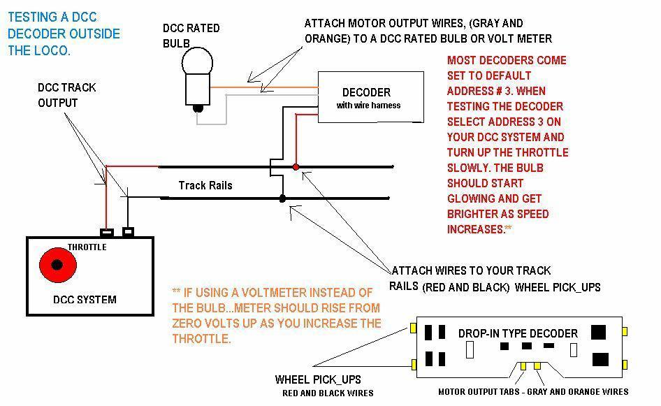
39 Constructing a Speaker Baffle: 39
GAUGEMASTER. DCC55 Prodigy Computer Interface
 DCC55 GAUGEMASTER DCC55 Prodigy Computer Interface Thank you for purchasing the Prodigy Computer Interface. It contains the hardware, (USB module) and computer interface software. It will allow your computer
CAB-05. Intermediate Cab
 CAB-05 Intermediate Cab Operation Manual This manual was written by the NCE Publications Department. Please address any comments to: NCE Publications Dept. 1260 Creek Street. Suite 100 Webster, NY 14580
Designed for use on all XpressNET systems
 Information LH100 V3 1 Designed for use on all XpressNET systems LH100 Keypad based Dispatcher's Throttle Version 3.0 art. no. 21100 1 st edition August 2000 Submitted to the NMRA for Conformance and Inspection
Calgary N-Scale Traksters Society Recommended Practice for DCC
 Table of Contents 1. Introduction 2 2. DCC 3 3. Electrical Bus 6 4. Trackwork 10 5. Assorted MRC DCC specific information 11 Page 1 of 13 1. Introduction Calgary N-Scale Traksters Society, commonly referred
LH100 Dispatcher s Throttle 1. Designed for use on all XpressNet systems
 LH100 Dispatcher s Throttle 1 Designed for use on all XpressNet systems LH100 Keypad based Dispatcher's Throttle Version 3.0 art. no. 21100 December 2002 LH100 Dispatcher s Throttle 2 Welcome! Congratulations
Electric Version 1. Programming Guide
 Electric Version 1 Programming Guide 3-1-2018 This manual covers the setup and configuration of the Sound Components of the WOWSound Electric decoder. All NMRA, Lighting, and Motor Control programming
POWERHOUSE. -- the finest in Digital Command Control -- PRODUCT MANUAL FOR PB-205a DUAL 5AMP POWER STATION
 POWERHOUSE TM -- the finest in Digital Command Control -- PRODUCT MANUAL FOR PB-205a DUAL 5AMP POWER STATION NCE Corporation 1260 CREEK STREET SUITE 100 WEBSTER NEW YORK 14580 FAX : (716) 671-9337 E-mail:
CAB-05. Intermediate Cab. Operations Manual. For Cab version 3.1
 CAB-05 Intermediate Cab Operations Manual For Cab version 3.1 Copyright 1994-2006 NCE Corporation Last revised: 13 September 2006 To the right is an illustration of the CAB05 Intermediate Cab. Following
GWire. System Reference Manual. Rev. 1.28d
 GWire System Reference Manual Rev. 1.28d 1 Push RED button to turn ON. Press PROG/ESC then 2 to turn OFF. Screw Antenna to top. Do not overtighten. 4 x AAA Batteries. Observe polarity. To select a locomotive
TEAM DIGITAL. DCCBreak DCC Circuit Breaker
 TEAM DIGITAL DCCBreak DCC Circuit Breaker Improving the world of DCC > Short and over current protection > Adjustable shutdown current level > Adjustable turn on delay > 4 amp continuous operation > Very
Hatton s DCC Decoder Instructions
 Hatton s DCC Decoder Instructions Thank you for purchasing one of our Hatton s DCC decoders. Our decoders meet all NMRA DCC specifications and will give good performance out of the pack, however by using
Mini Panel. Accy and Macro Controller. Build the kind of control panels you ve always wanted without complicated wiring!
 Mini Panel Accy and Macro Controller Dimensions: 3.0" x.70" (8 x 69 mm) Revision.00 $49.95 Build the kind of control panels you ve always wanted without complicated wiring! Use one button to control multiple
DCC Basics and Beyond. Lee Dobyns 4/25/2015
 DCC Basics and Beyond Lee Dobyns 4/25/2015 DCC Overview Why use DCC instead of DC Control more than one train on a track at the same time. Eliminates the need for blocks. Track wiring is simplified. Reversing
Digitrax Complete Train Control Starter Set Manual
 Complete T rain Control express Digitrax Complete Train Control Starter Set Manual Includes: DCS52 All In One Command Station Booster Throttle, PS314 Power Supply, LT1 Decoder & LocoNet Cable Tester Digitrax,
900 MHz Digital Two-Line Cordless Speakerphone with Answering System 9452 with Caller ID/Call Waiting
 USER S MANUAL Part 2 900 MHz Digital Two-Line Cordless Speakerphone with Answering System 9452 with Caller ID/Call Waiting Please also read Part 1 Important Product Information AT&T and the globe symbol
NCE DCC. Own a PowerCab or PH Pro DCC system? Need to know how to get it set up? Want to know what it can do? Presented by Tim s Trains and Hobbies
 Own a PowerCab or PH Pro DCC system? Need to know how to get it set up? Want to know what it can do? Presented by Tim s Trains and Hobbies Show the operating function and capabilities of the NCE DCC PowerCab
Using Digitrax Devices on a Non Digitrax DCC Controlled Layout Rev. 3 By Elmer McKay < >
 Using Digitrax Devices on a Non Digitrax DCC Controlled Layout Rev. 3 By Elmer McKay < emckay70@member.afa.org > The following information was written to help the Non-Digitrax user; use, control, and interface
NEWSLETTER VOLUME 23 - NO. 4 July- August 2011 Dr. Tom Catherall, Editor
 NEWSLETTER VOLUME 23 - NO. 4 July- August 2011 Dr. Tom Catherall, Editor New CS2 System Available Upgrades are regularly available for the CS2. Version 1.6.2 is the most current software at the time of
TEAM DIGITAL. SRC162e Switch & Route Controller
 TEAM DIGITAL SRCe Switch & Route Controller Improving the world of DCC > DCC compatible accessory decoder > Control switches (turnouts) > Drive switch status LEDs > Drive Tortoise switch machines > configurable
REVOLUTION DCC SYSTEM INSTALLATION AND OPERATION MANUAL
 REVOLUTION DCC SYSTEM INSTALLATION AND OPERATION MANUAL TENTATIVE DCC 5A Command / Booster Station /Mobile Receiver #59002 Revolution DCC Transmitter 'TX' #59001 15 AMP Station Command/Booster RX #59005
Digitrax Command Control Starter Set Manual
 R Complete T rain Control Digitrax Command Control Starter Set Manual Includes: DCS50 Command Station Booster, PS315 Power Supply, LT1 Locoet Cable & Decoder Tester Locoet Digitrax, Inc. 2443 Transmitter
WARNING NOT ZTC Controls Ltd
 WARNING If you fail to read the installation instructions properly it is possible that you could accidentally damage your ZTC unit. Such damage is NOT covered by our guarantee. So to prevent avoidable
MODERN TURNTABLE WITH DCC CONTROL BOX MANUAL
 Table of Contents 1. Operational Overview 2. Control Box Display and Function Keys 3. Operating with the Control Box 4. Operating in DCC (Digital) Mode 5. Operating Instructions and Hints 6. FAQs 7. Technical
Lionel icab version 2 User s Guide
 Lionel icab version 2 User s Guide 2017, Lionel LLC Table of Contents Introduction... 3 Connect to the LCS WiFi... 3 Launch icab... 3 Navigating Through icab s Views... 4 Swiping to access additional screens...
POWERHOUSE. -- the finest in Digital Command Control -- PRODUCT MANUAL FOR PB-110A TEN AMP POWER STATION
 POWERHOUSE TM -- the finest in Digital Command Control -- PRODUCT MANUAL FOR PB-110A TEN AMP POWER STATION NCE Corporation 1260 CREEK STREET Suite 105 WEBSTER NEW YORK 14580 FAX : (716) 671-9337 E-mail:
TEAM DIGITAL. CSCe Central Signal Controller
 TEAM DIGITAL Improving the world of DCC CSCe Central Signal Controller > Control signals on your layout > Compatible with the SHD2 > 6 inputs for sensors/switches > 6 outputs to drive LEDs > 2 outputs
TEAM DIGITAL. SRC16 Switch & Route Controller
 6 Cont. Summary of Configuration Variables CV# Function/Default Value CV# Function/Default Value 73 Route 3 Cell 7 Address Adder 0 25 Route 6 Cell 4 Address Adder 0 74 Route 3 Cell 8 Address 0 26 Route
2.4 GHz Cordless Telephone Answering System 2325/2365 with Caller ID/Call Waiting
 USER S MANUAL Part 2 2.4 GHz Cordless Telephone Answering System 2325/2365 with Caller ID/Call Waiting Please also read Part 1 Important Product Information 2002 Advanced American Telephones. All Rights
TEAM DIGITAL. BlocD8 High Density Block Detector. BlocD8
 TEAM DIGITAL Improving the world of DCC BlocD8 High Density Block Detector > 8 block detectors > Electrical isolation from the track > No track voltage drop > LED indicator for each block > 8 outputs for
Unleashing the Power of DCC
 Command Station LZ100 1 Unleashing the Power of DCC LZ100 Command Station Operations Manual Version 3.2 art. no. 20101 revised February 2001 Version 3.2 2 Command Station LZ100 Getting started To get started
Frequently Asked Questions
 Serene CL-60 Big Button Amplified Talking CID Cordless Phone W/ Display Screen Frequently Asked Questions Q: How can I turn off the "talking" voice? A: Just set the "talking" selection switch to Off in
Mark Schutzer December 9, 2007 (updated fix for older rev B and C ProCabs)
") Turning on radio ProCabs / PowerCabs Mark Schutzer December 9, 2007 (updated fix for older rev B and C ProCabs) Overview This paper will look into and explain why radio ProCabs / PowerCabs are hard to
Turning on radio ProCabs / PowerCabs Mark Schutzer December 9, 2007 (updated fix for older rev B and C ProCabs) Overview This paper will look into and explain why radio ProCabs / PowerCabs are hard to
Set-up and Use of your Wilson F/X Launch System
 WILSON F/X W F/X WIRELESS Wilson F/X Digital Launch Control Systems 903 East 6th Street, Sterling, IL 61081 www.wilsonfx.com Brad, the Rocket Rev., Wilson rocketrev@wilsonfx.com Tripoli #1630, L-3 NAR
The Universal Translator
 Universal Translator - Application and Installation! 1 The Universal Translator The Universal Translator! 1 Examples and Guidelines! 2 Application Notes! 4 Installing and Troubleshooting Your Translator!
REVISED 5/1/01. AT&T and the globe symbol are registered trademarks of AT&T Corp. licensed to Advanced American Telephones.
 REVISED 5/1/01 1 USER S MANUAL Part 2 1818 Digital Answering System Speakerphone Fold open this manual for information about this product s installation and operation. Please also read Part 1 Important
Run Your Trains, Not Your Track!
 Features: Complete Train Control Run Your Trains, Not Your Track! SDH164K1A Plug N Play for Kato AC4400 HO Locomotives. Light Board replacement decoder for motor, lights and sound. Preloaded with AC4400
Frequently Asked Questions
 Serene CL-60A Amplified Talking CID Cordless Phone with Slow-Play, Amplified Answering Machine Frequently Asked Questions Q: Base Charging Indicator is not on when handset is placed on the base. A: Move
Control. Complete. Digitrax, Inc Transmitter Road Panama City, Florida USA (850) Fax (850)
 Fax (850)") Complete T rain Control DT500 Series Digitrax Super Throttle Users Manual Includes: DT500 Series Throttles, DT500 IR Operation with UR90, DT500D Duplex Radio Operation with UR92 Digitrax, Inc. 2443 Transmitter
Complete T rain Control DT500 Series Digitrax Super Throttle Users Manual Includes: DT500 Series Throttles, DT500 IR Operation with UR90, DT500D Duplex Radio Operation with UR92 Digitrax, Inc. 2443 Transmitter
Press the PEN HOME key to move the pen(s) to the outside of the chart. The pen(s) is automatically raised off the chart.
 to the outside of the chart. The pen(s) is automatically raised off the chart.") DICKSON GETTING STARTED 7-day chart rotation 0 to 100 o F KT8P0/2/3 & KT856 Remote Sensing Temperature Recorder QUICK START 1. Remove the protective pen cap(s). 2. Connect Probe(s): a. KT8P0/2/3: Make
DICKSON GETTING STARTED 7-day chart rotation 0 to 100 o F KT8P0/2/3 & KT856 Remote Sensing Temperature Recorder QUICK START 1. Remove the protective pen cap(s). 2. Connect Probe(s): a. KT8P0/2/3: Make
Model IMP-22G2,H Low Cost Slave Clock Impulser Converts your slave clock to a working timepiece without modifying its original mechanism.
 Model IMP-22G2,H Low Cost Slave Clock Impulser Converts your slave clock to a working timepiece without modifying its original mechanism. The PIEXX IMP-22G2, H allows you to put your slave clock back into
NAME EET 2259 Lab 3 The Boolean Data Type
 NAME EET 2259 Lab 3 The Boolean Data Type OBJECTIVES - Understand the differences between numeric data and Boolean data. -Write programs using LabVIEW s Boolean controls and indicators, Boolean constants,
TEAM DIGITAL. SMD84 Switch Machine Driver with Serial Bus
 TEAM DIGITAL SMD84 Switch Machine Driver with Serial Bus Improving the world of DCC > DCC compatible accessory decoder > Drives 8 solenoid and/or stall type machines > 8 configurable routes > 13 Individually
Basic Computer and Mouse Skills Windows 10
 Basic Computer and Mouse Skills Windows 10 Hardware--is a term for the physical parts of the computer. The computer consists of four basic pieces of hardware. The Monitor The monitor displays the content
Decoder Installation:
 Decoder Installation: MOTOR Right Track Power Pickup Motor + Motor - RIGHT RAIL (Engineer's Side) Left Track Power Pickup LEFT RAIL (Fireman's Side) **Last revised: 15 February 2010 Page 2 TRKCAR-A Decoder
logic table of contents: squarebot logic subsystem 7.1 parts & assembly concepts to understand 7 subsystems interfaces 7 logic subsystem inventory 7
 logic table of contents: squarebot logic subsystem 7.1 parts & assembly concepts to understand 7 subsystems interfaces 7 logic subsystem inventory 7 7 1 The Vex Micro Controller coordinates the flow of
The PSX-1, 2, 3, 4 Series
 *800.671.0641 info@dccspecialties.com *Designed by Larry Maier *Developed by DCC Specialties *US Patent 7,810,435 The PSX-1, 2, 3, 4 Series DCC Circuit Breaker Intelligent, Solid State Block Detection
PC Model Railway Control System
 PC Model Railway Control System For the Hornby Elite and NMRA compliant DCC systems Version 1.01 Copyright 2010 by Invicto Systems Limited. All rights reserved. CONTENTS Installing Rail-Master 5 Setting
COMPUTER DESCRIPTION...
 Conventions used in this document: Keyboard keys that must be pressed will be shown as Enter or Ctrl. Controls to be activated with the mouse will be shown as Start button > Settings > System > About.
PRE-INSTALL QUESTIONS
 PRE-INSTALL QUESTIONS Is it really Plug and Play? Yes. The Navos comes with all the necessary plugs and harnesses to connect directly to your car; no extra adapters or dash trim kits required. Is the Navos
Run Your Trains, Not Your Track!
 Complete Train Control Run Your Trains, Not Your Track! SDH164K1C Plug N Play for Kato F40PH HO Locomotives. Light Board replacement decoder for motor, lights and sound. Preloaded with F40PH Sound Scheme
INTRODUCTION SAFETY INSTRUCTION FEATURES
 INTRODUCTION Thank you for your purchasing our newest Caller ID phone with phonebook function. This manual is designed to familiarize you with this phone. To get the maximum use from your new phone, we
DIGITAL ENHANCED CORDLESS TELEPHONE with Caller ID Function CL-3350 INF USER' S MANUAL
 DIGITAL ENHANCED CORDLESS TELEPHONE with Caller ID Function CL-3350 INF USER' S MANUAL Congratulations on purchasing our high quality product. Please read the manual carefully to find out all features
Digitrax Command Control Starter Set Manual
 R Complete T rain Control Digitrax Command Control Starter Set Manual TM Includes: DCS51 All In One Command Station Booster Throttle, PS314 Power Supply, LT1 LocoNet Cable & Decoder Tester LocoNet Digitrax,
Caller ID Telephone 962
 1 USER S MANUAL Part 2 Caller ID Telephone 962 Please also read Part 1 Important Product Information AT&T and the globe symbol are registered trademarks of AT&T Corp. licensed to Advanced American Telephones.
Switch-It Accessory Decoder
 Switch-It Accessory Decoder FOR STALL MOTOR SWITCH MACHINES ONLY NOT FOR USE WITH TWIN COIL SWITCH MACHINES Dimensions: 2.1" x 1.3" (54 x 33 mm) Decoder revision C $19.95 Now with EASIER PROGRAMMING! This
NEWSLETTER VOLUME 20 - NO. 6 November- December 2008 Dr. Tom Catherall, Editor
 NEWSLETTER VOLUME 20 - NO. 6 November- December 2008 Dr. Tom Catherall, Editor Märklin Digital Central Station Have you noticed the branding change from Märklin Systems to Märklin Digital with the new
HO-Scale Atlas DCC Sound Conversion Kit
 Our Famous GOOF PROOF Warranty WOWKit Compatibility for HO-Scale Atlas Locomotives Master Collection: Trainman Collection: ALCO RS-1 WDK-ATL-2 ALCO RS32/36 WDK-ATL-1 ALCO C420 WDK-ATL-3 EMD GP39-2 Ph.
USER GUIDE Revision 02
 USER GUIDE Revision 02 Please Read All Instructions Carefully Before Using Contents 1. Battery precautions... 2 2. Care & maintenance of Pro-Bot... 2 3. Battery requirements... 3 4. Installing batteries
The DB3a provides 5 Amps of additional power to an SB3a Smart Booster or other 5 Amp DCC system to run trains and accessories.
 NCE DB3a Booster The DB3a provides 5 Amps of additional power to an SB3a Smart Booster or other 5 Amp DCC system to run trains and accessories. Last Revised 2/5/10 1 DB3a Power Supply: The DB3a requires
GETTING STARTED. Installing the System 2000 Hardware. Configuring Your System 2000 Hardware. Troubleshooting. Configuring Your System 2000 Network
 SYSTEM 2000 GETTING STARTED Installing the System 2000 Hardware Whether you are upgrade an existing System 2, or this is a brand new installation, there will be some hardware installation involved. We
Documentation Updates for Version 4.3.2
 Documentation Updates for Version 4.3.2 A-Track Version 4.3.2 is a minor update to Version 4.3 which was released in November 2013. The Reference Manual, User Guide, and Installation Notes have been amended
Blackfin Online Learning & Development
 Presentation Title: Multimedia Starter Kit Presenter Name: George Stephan Chapter 1: Introduction Sub-chapter 1a: Overview Chapter 2: Blackfin Starter Kits Sub-chapter 2a: What is a Starter Kit? Sub-chapter
HO-Scale Kato DCC Sound Conversion Kit
 Our Famous GOOF PROOF NO Questions Asked Warranty WOWKit Compatibility for HO-Scale Bowser Locomotives DS 4-4-1000 WDK-BOW-1 S-12 WDK-BOW-2 C-636 WDK-BOW-3 Included in this WOWKit: HO-Scale Kato DCC Sound
SRC8 Switch & Route Controller
 12 CV# Function/Default Value CV# Function/Default Value 11 Group 3 Alt Address 0 56 Route 4 Cell 8 0 12 Group 4 Alt Address 0 57 Route 5 Switch State 0 13 Group 5 Alt Address 0 58 Route 5 Cell Address
Quick Start. What s in the Box. a - AirBand wireless Bluetooth stereo headset b - USB charging cable c - AC power adapter
 INSTRUCTION MANUAL Thank you for purchasing the GOgroove AirBand wireless Bluetooth stereo headset. The wireless Bluetooth capability enables you to listen to music anytime without getting tangled up in
900 MHz Cordless Answering System with Caller ID/Call Waiting 9357 DRAFT 7/6/01
 9357_book/wc_1ATT 7/6/01 4:10 PM Page ii USER S MANUAL Part 2 900 MHz Cordless Answering System with Caller ID/Call Waiting 9357 DRAFT 7/6/01 Please also read Part 1 Important Product Information AT&T
AT&T MDW 9000 Wireless Telephone Quick Reference
 AT&T MDW 9000 Wireless Telephone Quick Reference Contents Handset Controls Handset Display Line Status Indicators Call Alerter Charging Cradle Controls Troubleshooting Wireless Test Mode MDW 9000 Compatibility
2.4 GHz Cordless Speakerphone 2440 with Caller ID/Call Waiting
 1 USER S MANUAL Part 2 2.4 GHz Cordless Speakerphone 2440 with Caller ID/Call Waiting Please also read Part 1 Important Product Information AT&T and the globe symbol are registered trademarks of AT&T Corp.
Emergency Dialer Monitoring Station
 www.skylinkhome.com Emergency Dialer Monitoring Station MODEL: MS-2001 TM P/N. 101A128 DEC, 2000 SKYLINK TECHNOLOGIES INC., 2213 Dunwin Drive, Mississauga, Ontario L5L 1X1 CANADA Tel : (905) 608-9223 (800)
Lenz Digital Plus DCC
 Page 1 Lenz Digital Plus DCC Lenz Digital Plus DCC technology was offered to the NMRA as a basis for the NMRA DCC standard back in 1991. The Lenz technology was opened to all other manufacturers then and
The Digital Center for PC. Manual
 The Digital Center for PC Manual Table of Contents IB-COM 1. The Digital Center IB-COM... 3 1.1 Description... 3 1.2 Technical Data... 4 2. The Interface... 5 2.1 Interface Characteristics... 5 2.2 Preparation
X10 on the P&P Layout. Quick Tip! Quick Tip! T
 Quick Tip! Trackside LED s help troubleshoot track power problems. If the LED is Green there is power to the track. If the LED is Red there is power available but it is not going to the track. If the LED
By Mark Schutzer PCR Regional Convention, Dublin, CA April 2013 Copies of this presentation can be found at
 A Beginners Guide to Installing DCC Decoders By Mark Schutzer PCR Regional Convention, Dublin, CA April 2013 Copies of this presentation can be found at http://www.markschutzer.com Clinic Overview Installing
AT&T and the globe symbol are registered trademarks of AT&T Corp. licensed to Advanced American Telephones.
 1 USER S MANUAL Part 2 Tapeless Digital Answering System Telephone with Time/Day 1817 Fold open this manual for information about this telephone s installation and operation. Please also read Part 1 Important
Get Started with Kindle (2nd Generation)
") Get Started with Kindle (2nd Generation) Get Started with Kindle 2nd (Generation) Charge and Power Up Your Kindle Register Your Kindle Set a Password on Kindle Use the Home Screen Charge and Power Up Your
Get Started with Kindle (2nd Generation) Get Started with Kindle 2nd (Generation) Charge and Power Up Your Kindle Register Your Kindle Set a Password on Kindle Use the Home Screen Charge and Power Up Your
Our Famous GOOF PROOF Warranty
 Our Famous GOOF PROOF Warranty TM MTC21-Pin Connector Scale Functions Function Rating Continuous/Peak HO 8 100 ma 1.3 /2.0 Amp Dimensions: 1.28 x.69 x.22 or 32.5mm x 17.5mm x 5.6mm Main Features of this
VIZTRAC. VIZTRAC User s Guide STANDARD FIXED HEAD 100' 130' 150' A. 200' 225' AM 100 AM 200 AM hz Built-In Sonde AM 140 AM 200B AM 240B
 VIZTRAC 3807 Old Tasso Rd. NE Cleveland, TN 37312-5732 VIZTRAC User s Guide STANDARD FIXED HEAD 100' 130' 150' A 200' 225' AM 100 AM 200 AM 240 512hz Built-In Sonde AM 140 AM 200B AM 240B DVR Quick Start
Jabra FREEWAY. User manual.
 Jabra FREEWAY User manual www.jabra.com CONTENTS THANK YOU...2 ABOUT YOUR...2 WHAT YOUR SPEAKERPHONE CAN DO...3 GETTING STARTED...4 CHARGE YOUR SPEAKERPHONE...4 TURNING YOUR SPEAKERPHONE ON AND OFF...5
Automatic Phone-Out Home Monitoring System
 Automatic Phone-Out Home Monitoring System Freeze Alarm Model Number: THP217 Product Description This product is intended to monitor homes, cabins, and other premises for low temperature conditions. It
Harbortronics Time-Lapse Package Troubleshooting Guide This document is intended to help diagnose any problems with your Time-Lapse Package.
 This document is intended to help diagnose any problems with your Time-Lapse Package. Power Everything in the Time-Lapse Package (TLP) is powered by the large Lithium-Ion Polymer battery pack, made specifically
Controller Pro Instruction Manual
 Controller Pro Instruction Manual These instructions cover: Installing Controller Pro Programming Troubleshooting Doc# Doc120-017 Revision: D ECO: 102208 Note: Document revision history and EC information
GEN 6 LOCKPICK INSTALLATION OPTIONS COPYRIGHT 2010 COASTAL ELECTRONIC TECHNOLOGIES, INC.
 AFTERMARKET FRONT/BABY CAMERA VIDEO CONNECT HERE FRONT/BABY CAM POWER TO LOCKPICK RED W/BLACK STRIPE WIRE TO LOCKPICK BLACK GROUND WIRE UNPLUG ORIGINAL RADIO CONNECTORS THEN PLUG IN HERE PLUG AND PLAY
Division Services. Model: DPAS-300. Division Portable Bulk Load Accumulator Scale INDUSTRIAL PH (901) FAX (901)
 FAX (901)") Division Services 5680 E. Shelby Drive Memphis, TN 38141 PH (901) 366-4220 FAX (901) 365-3934 Model: DPAS-300 VERSION 5 Division Portable Bulk Load Accumulator Scale INDUSTRIAL Division Model DPAS-300
Division Services 5680 E. Shelby Drive Memphis, TN 38141 PH (901) 366-4220 FAX (901) 365-3934 Model: DPAS-300 VERSION 5 Division Portable Bulk Load Accumulator Scale INDUSTRIAL Division Model DPAS-300
1738 Digital Answering System USER S MANUAL. Visit us at Part 2
 1738_Panels 120904 12/9/04 8:25 AM Page 1 Visit us at www.telephones.att.com 2004 Advanced American Telephones. All Rights Reserved. AT&T and the Globe Design are trademarks of AT&T Corp., licensed to
Controller Pro Instruction Manual
 Controller Pro Instruction Manual These instructions cover: Installing Controller Pro Programming Troubleshooting Doc# Doc120-017 Revision: B ECO: 010507 Note: Document revision history and EC information
SDXN146K1E SoundFX Drop in Mobile Decoder for Kato N Scale SD40-2 and similar Locomotives 8 Selectable Steam & Diesel Sound Schemes Included
 Features: Complete Train Control Run Your Trains, Not Your Track! SDXN146K1E SoundFX Drop in Mobile Decoder for Kato N Scale SD40-2 and similar Locomotives 8 Selectable Steam & Diesel Sound Schemes Included
The timer has several functions: count-down timer with voice report; count-up timer without voice report; and talking clock.
 Instructions for Talking Up/Down Timer LIV-041-329-0001 Getting to know your timer: The timer has several functions: count-down timer with voice report; count-up timer without voice report; and talking
INTRODUCTION CT87E FEATURES AND CONTROLS
 INTRODUCTION The CT87E is a precision instrument used to monitor and record the presence or absence of voltage, light, or sound level such as what would be produced by an operating electric motor or compressor.
The ACE is the result of over two years development work. We asked ourselves a simple, but challenging, question.
 Announcing the ACE! Introduction A new DCC controller! Bringing model railway control into the 21 st century! Low cost, but rich with features! Complete and flexible control, but easy to use! Fully NMRA-compliant!
ADDITIONAL CAM POWER REVERSE CAM POWER BLUETOOTH MUTE AUDIO + IN AUDIO - IN 12V ACC OUTPUT 12V CONSTANT GROUND
 UNPLUG ORIGINAL RADIO CONNECTORS THEN PLUG IN HERE PLUG AND PLAY NO OTHER CONNECTIONS ARE NECESSARY USE HANDSFREE KIT MICROPHONE IPOD/IPHONE/ITOUCH/IPAD CONNECTION USB INPUT ADD YOUR BLUETOOTH HANDSFREE
Robolab. Table of Contents. St. Mary s School, Panama. Robotics. Ch. 5: Robolab, by: Ernesto E. Angulo J.
 Robolab 5 Table of Contents Objectives...2 Starting the program...2 Programming...3 Downloading...8 Tools...9 Icons...9 Loops and jumps...11 Multiple tasks...12 Timers...12 Variables...14 Sensors...15
The PSX-AR Series. New Exclusive Digitrax Configuration New Timing Delay Features New Programmable Power Up Status New Auto Stop For DCC Use Only
 *800.671.0641 info@dccspecialties.com *Designed by Larry Maier *Developed by DCC Specialties *US Patent 7,810,435 The PSX-AR Series DCC Circuit Breaker & Auto Reverser Integrated Turnout Control for Loop
Battery Charging The tablet has a built-in rechargeable Li-polymer battery.
 Attention: This handbook contains important security measures and the correct use of the product information, in order to avoid accidents. Pls make sure to reading the manual carefully before use the device.
ATD-5493 Wireless Battery System Tester
 ATD-5493 Wireless Battery System Tester For Testing 6V & 12V Vehicle Batteries individually & in Battery Packs. Also for testing 6V, 12V, 24V and 36V Charging & Starter Systems User Manual Remote Battery
Appendix 8 Universal Powerline Bus (UPB)
") Appendix 8 Universal Powerline Bus (UPB) This appendix describes the features in HCA in support of the UPB technology and products available from Powerline Control Systems (PCS), Simply Automated Inc,
Appendix 8 Universal Powerline Bus (UPB) This appendix describes the features in HCA in support of the UPB technology and products available from Powerline Control Systems (PCS), Simply Automated Inc,
Secured Series: Hub Plus Kit Single Door Controller Package Installation Manual
 Secured Series: Hub Plus Kit Single Door Controller Package Installation Manual This package is designed to simplify the connections to our Secured Series Hub Plus Controller. This will translate into
ELECTRONIC CLASSROOM OPERATIONS GUIDE Room 501 V4.01
 1 Under Construction Under Construction ELECTRONIC CLASSROOM OPERATIONS GUIDE Room 501 V4.01 CONTENTS Under Construction I. START OF CLASS/START OF DAY PROCEDURES... 2 II. CHANGING BETWEEN COMPUTER DISPLAY
StudioPrompter Tutorials. Prepare before you start the Tutorials. Opening and importing text files. Using the Control Bar. Using Dual Monitors
 StudioPrompter Tutorials Prepare before you start the Tutorials Opening and importing text files Using the Control Bar Using Dual Monitors Using Speed Controls Using Alternate Files Using Text Markers
LCD MODULE INSTRUCTIONS
 LCD MODULE INSTRUCTIONS Overview: The LCD Module is an optional module that allows live data to be displayed right in your vehicles dash. It is completely customizable and shows 10 separate channels of
Air Hockey v7.0 Controller PCB Air Hockey 10v Transformer
 KNOWN ISSUES SORTED BY BOARD REVISION DYNAMO HOCKEY PCBs LISTED IN THIS WORKSHEET are no longer available for purchase or serviced by the manufacturer. Most tables can be upgraded to Dynamo s latest v7.0