Digital EPIC D460/D470 For Rotary, Linear and Standard Applications Operating Manual
|
|
|
- Claude Blair
- 6 years ago
- Views:
Transcription


1 1. Manual Scope Digital EPIC D460/D470 For Rotary, Linear and Standard Applications Operating Manual This manual contains installation, wiring, configurations and calibration instructions of the Digital EPIC D460/D470 in standard applications for both rotary and linear actuators. These transmitters are microprocessor-based devices, providing both 4-20 ma signal for position feedback and digital communications via the HART protocol for data evaluation and diagnostics. 2. Symbols Used in this Document This symbol warns the user of possible danger. Failure to heed this warning may lead to personal injury or death and/or severe damage to equipment. This symbol identifies information about operating the equipment in a particular manner that may damage it or result in a system failure. Failure to heed this warning can lead to total failure of the equipment or any other connected equipment. This symbol draws attention to information that is essential for understanding the operation and/or features of the equipment. 10/27/06 Tech-376/ D.W.O of 11
2 3. D-Epic Mounting Instructions 3.1 Mounting D-EPIC on a Rotary Actuator Instructions Press fit the inner beacon to the inner beacon coupler. The inner beacon needs to be properly oriented. Use the symbols on the top of the inner beacon to orient correctly during installation as shown in Condition 1 or Condition 2 (See Figures 1 and 2 below). IMPORTANT: Condition 1 and Condition 2 show the placement of the inner beacon with respect to the positioner housing while the actuator is in the fail position. Condition 1-Actuator fails in a clockwise direction. Condition 2-Actuator fails in a counter clockwise direction. IMPORTANT NOTE: INNER BEACON "b" AND UNIT SENSOR "b" NEED TO BE ALIGNED IMPORTANT NOTE: INNER BEACON " " AND UNIT SENSOR "b" NEED TO BE ALIGNED Figure 1 Figure 2 10/27/06 Tech-376/ D.W.O of 11
3 3.2 Mounting the DEPIC on a Linear Actuator Instructions To Center the DEPIC: Stroke the actuator to its upper limit and place a mark on the actuator s yoke that lines up with the red arrow on the magnet assembly Stroke the actuator to its lower limit and place a mark on the actuator s yoke that lines up with the red arrow on the magnet assembly Place a third mark on the yoke centered between the upper and lower limit marks Place Lastly, mount the DEPIC to the bracket so that the conduit entry (@ 9:00) faces away from the diaphragm or cylinder (@ 12:00). Figure 3 NOTE: For Fisher actuators model 657 & 667 sizes 34 thru 70, Westlock Controls supplies a slotted mounting kit, to ease the mounting process. This will allow the user to easily center the positioner sensor between the limits of the magnet assembly s stroke. 10/27/06 Tech-376/ D.W.O of 11
4 4. D-EPIC Wiring Instructions All wiring must be in accordance with National Electrical Code (ANSI-NFPA-70) for the appropriate area classifications. All wiring must be in accordance with National Electrical Code (ANSI-NFPA-70) for area classifications. The valve monitors are approved for Class I, Division 1, Groups B, C and D; Aex dii B + H 2 ; Class I, Division 2, Groups A, B, C and D and AEx na (zone 2) Enclosure Type 4 IP67. Always check the nameplate to make sure the agency approval ratings coincide with the application. The proper wiring diagram for your unit is shown on the inside of the enclosure cover. Confirm that the area is known to be non-hazardous before opening the cover of a network monitor and making or breaking any electrical connections. 10/27/06 Tech-376/ D.W.O of 11
5 Remove Cover and terminate twisted shielded cable to terminal J1. Figure 4 SELECT NEXT Two wire 4 to 20 ma current sink (Current is proportional to the position) with 10 VDC Min. to 30 VDC Max. across the Output terminals. Terminal block accepts 14 to 22 AWG wire Analog Input Connection polarity insensitive SOL COIL SOL PWR For Hart Applications the auxiliary resistance is necessary only if unit is energized without an Analog input card or with any device with negligible impedance. Hart hand held needs to be connected down stream of the optional resistance. 5. D-EPIC Configuration Instructions The Configuration Menu (Cnfg) has two parameter menus. Cnfg is displayed in LCD upper right side. Each of the following selections will appear in LCD lower right side until selected where it then moves to LCD upper right side. 5.1 Type This allows the user to select the valve type, rotary (Rot) or linear (Lin). The factory default is rotary. Type appears in upper right side and the possible selections appear in LCD lower right side. 5.2 FLOP This allows the user to select how the current valve position is displayed in LCD sector 1, either as percent open (OFF) or as percent closed (ON). The factory default is percent open (OFF). FLOP appears in LCD upper right side and the possible selections appear in LCD lower right side. Follow the Keypad Menu Flow Diagram. 10/27/06 Tech-376/ D.W.O of 11
6 Keypad Menu Flow Diagram 10/27/06 Tech-376/ D.W.O of 11
7 6. D-Epic Calibration Instruction 6.1 Pushbutton Procedure Utilize the Select and Next pushbuttons on the PCB Assembly (Figure 5) in the enclosure to calibrate the D-EPIC. SELECT NEXT Quick Calibration: Note: Select Key = Red Button Next Key = Black Button Figure Press the select key until Ma Calb is displayed Press the select key until CLS? is displayed Stroke the valve to the de-energized position (Valve Closed) Once the de-energized position (Valve Closed) is achieved press select to calibrate this position as the CLS (Closed) one Display shows OPN? as soon as the low Calibration is achieved Before pressing any keys, stroke the valve to the energized position (Valve Opened) Once the energized position (Valve Opened) is achieved press select to calibrate this position as the OPN (Opened) one Display shows Calb Pass as soon as calibration is completed Then press the Next Key until Exit is displayed on the LCD Once exit is displayed press the Select Key to exit calibration. 10/27/06 Tech-376/ D.W.O of 11

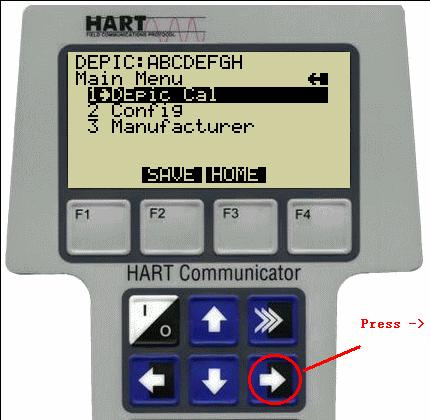
8 6.2 HART Rosemount 275 Procedure Connect D-EPIC to HART Handheld Select Main Menu by pressing Key Select D-EPIC Cal by pressing Key. 10/27/06 Tech-376/ D.W.O of 11

9 6.2.4 Once D-EPIC selected Calibration process can be aborted by pressing F3 key Calibration process can be continued by pressing F4 key First close the valve and wait until the valve fully reaches the closed position Calibration Process can be aborted by pressing F3 key Calibration process can be continued by pressing F4 key. 10/27/06 Tech-376/ D.W.O of 11
10 6.2.6 Now open the valve and wait until the valve fully reaches the open position Calibration process can be aborted by pressing F3 key Calibration process can be continued by pressing F4 key Finish and except the new calibrated value To reject new calibrated value, and set back old value, select ABORT by pressing F3 key To except new calibrated value, select OK by pressing F4 key. Note: Wait 5 seconds before doing this Operation Return to online menu to read current output values by pressing key once. This screen may view any calibration error flag. 10/27/06 Tech-376/ D.W.O of 11
. 6.3.")
11 6.3 Hart Rosemount 275 & ALTEC 334 loop Calibrator Procedure Disconnect both input wires from the D-Epic transmitter On the ALTEK Loop Calibrator move the slide switch to the ma position, the left toggle switch to the Source position and the right toggle switch to the Adjust position. Short the output leads together then turn thee adjustment knob until the display shows full-scale output (usually 24.0 ma) Connect the black lead (-) to one pin of the D-EPIC transmitter input connector (J1). Connect the red lead (+) to a 250-Ohm 1/4W resistor. Connect the other end of the 250-Ohm resistor to other pin of the EPIC transmitter input connector (J1) Connect the leads of the HART 275 Communicator to TP1 and TP2 of the D- EPIC transmitter. Note: The Loop calibrator does not control the D-Epic it only supplies current for it to operate. The D-EPIC will draw (sink) current in proportion to the valve position (usually 4.0 ma with the valve Closed and 20.0 ma with the valve current for the EPIC to operate. This is why the Loop Calibrator is set to 24.0 ma so that it can supply enough current for the EPIC to operate when the EPIC draws 20 ma. 10/27/06 Tech-376/ D.W.O of 11
Do not open when energized or when an explosive atmosphere is present. Electrostatic hazard, clean only with damp cloth.
 D460/D470 Series - ATEX certified position transmitter nnnn II 2 GD ITS 11 ATEX 17431X Ex d IIC T* Gb Tamb -*ºC to +*ºC Ex tb IIIC T* Db Tamb -*ºC to +*ºC IP6X Ambient variation -60 C to +110 C (T4/T130
Foundation Fieldbus 5400-IS ICoT Positioner
 Foundation Fieldbus 5400-IS ICoT Positioner Installation and Operation Manual 1. Revision History 1.1.Revision 1.0 24 March, 2003 Initial Version 1.2 Revision 1.2 4 May, 2005 Updated content and included
MTII4200 Level Transmitter Installation, Operation & Maintenance Instructions
 Specialists in Liquid Level Indication MTII4200 Level Transmitter Installation, Operation & Maintenance Instructions Section: M500 Bulletin: M500.31 Date: 05-17-16 Supersedes: 09-30-11 1. INTRODUCTION
Installation & Operating Instructions for SmartCal Valve Positioner
 w ANALOG POSITIONERS Installation & Operating Instructions for SmartCal Valve Positioner Rev G 04/20/01 tech-251/dwo11819 Page 1 of 33 Table of Contents Section 1 - Introduction Page 1.1 Description of
Powermite 599 MT Series SAS Electronic Valve Actuator 24 Vac or 24 Vdc, Proportional Control
 Powermite 599 MT Series SAS Electronic Valve Actuator 24 Vac or 24 Vdc, Proportional Control Description Features Application The Powermite 599 MT Series SAS Electronic Valve Actuator requires a 24 Vac
K10 Intrinsically Safe Electro-Pneumatic Positioner Operating Manual
 K0 Intrinsically Safe Electro-Pneumatic Positioner Operating Manual Pneumatic Connection Single Acting Actuator (Spring Return): For single acting actuators Outlet Port 2 is to be plugged. Outlet Port
Installation and operating instructions
 To be used in conjunction with the relevant VCIOM-04592 for the D510/520 or VCIOM-04979 for the D530/540/550 short form installation and operating manuals Table of contents 1. Introduction... 2 1.1 Product
Proximity Positioner. ICoT. Valve Monitoring and Control Products WESTLOCK
 Proximity Positioner UNLIKE CONVENTIONAL POSITIONERS, THE ICOT POSITIONER FEEDS BACK VALVE POSITION WITHOUT THE NEED FOR LINKAGES OR LEVERS. Non-contact position feedback is accomplished through the use
Rotork Fairchild PAX1 Linear Actuator User s Manual
 Rotork Fairchild PAX1 Linear Actuator User s Manual Product Overview The PAX1 is a flexible low voltage DC powered linear actuator featuring a 5 mm maximum thrust rod stroke moving at speeds up to 0 mm/min
Digital Proportional Valve Amplifier
 Digital Proportional Valve Amplifier The Amplifier is a compact, low profile DIN mounted controller for use with proportional solenoid valves. The provides current to a valve coil in proportion to an input
Smart Wireless THUM Adapter
 Quick Installation Guide Smart Wireless THUM Adapter Smart Wireless THUM Adapter Start Wireless Considerations Step 1: Physical Installation Step 2: Verify Operation Reference Information Product Certifications
VA-7700 Series. Electric Valve Actuators. Product Bulletin
 VA-7700 Series Electric Valve Actuators Product Bulletin The VA-77xx Series synchronous motor driven actuator, for valves in heating, ventilation and air conditioning applications, is available for floating
AVID SmartCal Valve Positioner - Figure 793 Installation & Operating Instructions
 Installation and operating instructions for the AVID SmartCal Intelligent Valve Positioner. Contents 1 Introduction 1 1.1 Description of SmartCal 1 1.2 Principal of Operation 1 2 Initial Setup 2 2.1 Mounting
Scanner 2000 microefm QuickStart. Installing the Scanner Remote Mount. Direct Mount NUFLO. Part No , Rev. A
 NUFLO Part No. 30165024, Rev. A Scanner 2000 microefm QuickStart Installing the Scanner 2000 H L H L Flow Direct Mount To install the Scanner 2000 microefm using a direct mount to an orifice or cone meter
MAN-652-OM1. 3 Oct 07 Revision G.R. G.A. 2 Jun 06 Revision A.G. G.A. 1 Feb 06 Revision A.G. G.A. Rev. Date DESCRIPTION Prepared Approved
 MAN-652-OM1 3 Oct 07 Revision G.R. G.A. 2 Jun 06 Revision A.G. G.A. 1 Feb 06 Revision A.G. G.A. 0 Sept 2005 First Issue A.G. G.A. Rev. Date DESCRIPTION Prepared Approved Note: Biffi Italia has taken every
SRD Z Intelligent Positioner stainless steel (316L)
") Quick Guide 09.2014 QG EVE0105 C-(en) SRD991- - Z Intelligent Positioner stainless steel (316L) These instructions are to be used as a guide for quick start-up. Versions with LCD, Amplifier Spoolvalve
Quick Guide 09.2014 QG EVE0105 C-(en) SRD991- - Z Intelligent Positioner stainless steel (316L) These instructions are to be used as a guide for quick start-up. Versions with LCD, Amplifier Spoolvalve
Keystone OM1 - EPI-2 modulating input/output module Installation and Maintenance Instructions
 Before installation these instructions must be fully read and understood Index 1. Optional module 1: Modulating I/O module... 1 2. Installation... 2 3. OM1 card setting and configuration... 6 4. Monitor
VVP10-H HART VALVE POSITIONER. Great Performance, Compact, Robust in Severe Conditions* HART 7 Communication Protocol. Electronic Coil Technology
 VVP10-H HART VALVE POSITIONER Great Performance, Compact, Robust in Severe Conditions* HART 7 Communication Protocol Electronic Coil Technology Non-Contact Position Sensor (Hall Sensor) 4-20 ma NAMUR NE
CDD Carbon Dioxide Transmitter
 Introduction The OSA CO2 transmitter uses Infrared Technology to monitor CO2 levels within a range of 0 2000 ppm and outputs a linear 4-20 ma or 0-5/0-10 Vdc signal. The enclosure is designed to operate
INSTALLATION INSTRUCTIONS
 www.altroniccontrols.com INSTALLATION INSTRUCTIONS EXACTA 21 MONITORING AND CONTROL SYSTEM CAUTION: The EXACTA 21 CONTROL SYSTEM is CSA CERTIFIED FOR use in Class I, GROUPS C & D, Division 2 hazardous
DVC2000 Series FIELDVUE Digital Valve Controllers
 Product Bulletin DVC2000 Series DVC2000 Series FIELDVUE Digital Valve Controllers The DVC2000 Series digital valve controller (see figure 1) is simple to use, compact, and designed for easy mounting. It
CDD4 Series Room CO2 Transmitter Installation Instructions
 CDD4 Series Room CO2 Transmitter Installation Instructions Introduction The CO2 transmitter uses Infrared Technology to monitor CO2 levels and outputs a linear 4-20 ma or 0-5/0-10 Vdc signal. Options include
The TVC Positioner is designed to provide precise position control of rotary or linear hydraulic or pneumatic actuated valve systems.
 TVC Positioner Introduction The TVC Positioner is designed to provide precise position control of rotary or linear hydraulic or pneumatic actuated valve systems. Key Features l Comprehensive diagnostics
1. Installation. 2. Configuration - Operation. 3. Specifications. Safety
 Safety 1. Installation 1.1 OP_ext: Services 1.2 Driver Card Installation 1.3 Sensor Types 1.4 Sensor Wiring 1.5 Controller Wiring 2. Configuration - Operation 2.1 Replaces ph Sensor 2.2 AS -Flex Series
Table of Contents. General Information. Document Sure-Aire Flow Monitoring System. User and Service Manual WARNING CAUTION
 Document 476092 User and Service Manual Installation, Operation and Maintenance Manual Please read and save these instructions for future reference. Read carefully before attempting to assemble, install,
Keystone OM1 - EPI-2 modulating input/output module Installation and Maintenance Instructions
 Before installation these instructions must be fully read and understood Index 1 Optional module 1: Modulating I/O module... 1 2 Installation... 2 3 OM1 card setting and configuration... 6 4 Monitor relay
MODBUS RTU I/O Expansion Modules - Models C267, C277, and C287. Installation and Operations Manual Section 50
 MODBUS RTU I/O Expansion Modules - Models C267, C277, and C287 Installation and Operations Manual 00-02-0651 09-01-09 Section 50 In order to consistently bring you the highest quality, full featured products,
PLEASE READ INSTRUCTIONS CAREFULLY BEFORE INSTALLATION!
 TUC2 / TUCH2 Model Series Installation Instructions PLEASE READ INSTRUCTIONS CAREFULLY BEFORE INSTALLATION! APPLICATION The TUC2 provides temperature space monitoring with a backlit LCD. The TUCH2 provides
This Datasheet for the IC660BBA104. Block 115Vac/125Vdc Analog Current Source 4 Inputs / 2 Outputs
 This Datasheet for the IC660BBA104 Block 115Vac/125Vdc Analog Current Source 4 Inputs / 2 Outputs http://www.qualitrol.com/shop/p-14425-ic660bba104.aspx Provides the wiring diagrams and installation guidelines
CT: Conductivity-Temperature
 Safety 1. Installation 1.1 CT:Services 1.2 Driver Card Installation 1.3 Sensor Types 1.4 Sensor Wiring 2. Configuration - Operation 2.1 Range Selection 2.2 Diagnostics 3. Specifications Safety 5 VDC, 1V
Digital EPIC Control Transmitters Weatherproof, Intrinsically Safe - ATEX/IEC
 Weatherproof, Intrinsically Safe - ATEX/IEC Discrete position control and precision, non-contact position feedback with digital communication via HART protocol in a simple, integrated package. With options
VALVE NETWORKING MONITORING AND CONTROL. Monitoring and Control Products & CApabilities
 VALVE NETWORKING MONITORING AND CONTROL Monitoring and Control Products & CApabilities 2 monitoring And control Automation Systems CONTROLS WELCOME TO WESTLOCK CREATING EFFICIENCY FROM COMPLEXITY ACTUATION
Smart Wireless THUM Adapter
 Reference Manual Smart Wireless THUM Adapter www.rosemount.com Reference Manual Smart Wireless THUM Adapter Smart Wireless THUM Adapter Smart Wireless THUM Adapter Hardware Revision 1 HART Device Revision
CDD4 Duct Carbon Dioxide Transmitter
 Drill or punch a 1-1/8 or 1-1/4 hole in the duct at the preferred location and insert the probe into the hole to mark the enclosure mounting holes. Remove the unit and drill the four mounting holes. Clean
FIELDVUE DVC6200 and DVC6200f Digital Valve Controller Management of Change Guide
 Fisher FIELDVUE DVC6200 and DVC6200f Digital Valve Controller Management of Change Guide 2011 Fisher Controls International LLC. All rights reserved. MY30 (H:) TABLE OF CONTENTS Background... 3 Management
Table of Contents 1. Overview Installation...6
 (2003-01-31) Table of Contents 1. Overview...1 1.1. Introduction... 1 1.2. Product Description... 1 1.2.1. Mechanical Actuator Assembly with M2CP Electrical Enclosure... 1 1.2.2. Variable Frequency Controller
Safety. 1. Installation 1.1 CR:Services 1.2 Driver Card Installation 1.3 Sensor Types 1.4 Sensor Wiring
 Safety 1. Installation 1.1 CR:Services 1.2 Driver Card Installation 1.3 Sensor Types 1.4 Sensor Wiring 2. Configuration - Operation 2.1 Setup-Calibration 2.2 Diagnostics 3. Specifications Safety 100mV
I ntroduction. RA Fast Running Electric Actuator. Features and Benefits
 European Electronic Controls Catalogue Section E Product Bulletin RA-3100-8026 Issue Date 0303 RA-3100-8026 Fast Running Electric Actuator I ntroduction The RA-3100 series synchronous motor-driven reversible
Oldham OLCT 200 Revision 1
 HART Field Device Specification: Oldham OLCT 200 Revision 1 Initial release: 13 April 2011 Current release: 13 April 2011 Part Number: 77036008 Revision: 02.1 HART is a registered trademark of the HART
This Datasheet for the IC660BBA026. Block 24/48Vdc Analog Current Source 6 Inputs.
 This Datasheet for the IC660BBA026 Block 24/48Vdc Analog Current Source 6 Inputs http://www.cimtecautomation.com/parts/p-14421-ic660bba026.aspx Provides the wiring diagrams and installation guidelines
FIELDVUE DVC5000f Series Digital Valve Controllers for FOUNDATION fieldbus
 DVC5000f Series FIELDVUE DVC5000f Series Digital Valve Controllers for FOUNDATION fieldbus Instruction Manual Form 5445 Introduction Installation Initial Setup and Calibration Detailed Setup Calibration
JERGUSON MTII4300. Installation, Operation, & Maintenance Instructions IOM M per CDC
 Installation, Operation, & Maintenance Instructions per CDC-17-251 2017.09 JERGUSON MTII4300 Table of Contents 1. INTRODUCTION... 3 2. PRODUCT DESCRIPTION... 4 2.1 MTII4300 TM Transmitter Specifications...
User s Manual Pulse Encoder Interface Module OTAC-01
 Drive IT Low Voltage AC Drives User s Manual Pulse Encoder Interface Module OTAC-01 2 Safety WARNING! All electrical installation and maintenance work on the drive should be carried out by qualified electricians
Series 3700 Screw Terminal Assemblies Installation Instructions
 Keithley Instruments, Inc. 28775 Aurora Road Cleveland, Ohio 44139 1-888-KEITHLEY www.keithley.com Series 3700 Screw Terminal Assemblies Installation Instructions Introduction This document contains handling
Sidewinder Pumps Inc. AC C1D2 Timer/Controller
 Sidewinder Pumps Inc. AC C1D2 Timer/Controller Page 1 of 14 Rev 4/26/17 Table of Contents 1. Warnings --------------------------------------------------------------------------------------------------
Safety. 2. Configuration - Operation 2.1 RTD Selection 2.2 Driver Test Header. 3. Diagnostics 3.1 ph Input 3.2 Temperature Input
 Safety 1. Installation 1.1 PT:Services 1.2 erature Compensation of 1.3 Controller Services 1.4 Driver Card Installation 1.5 Sensor Part Numbers 1.6 Sensor Wiring 2. Configuration - Operation 2.1 Selection
Differential Liquid/Gas Pressure Transmitter
 Installation Instruction Differential Liquid/Gas Pressure Transmitter Catalog Number(s) 1414-CPZ10FWFAA, 1414-IPZ10FWFAA Explosion Hazard WARNING Do not use in an explosive or hazardous environment, with
Standard Options. Model 4100 Position Indicating Meter. Three Phase Motor Control. Positran Transmitter
 Standard Options Model 4100 Position Indicating Meter A percent-of-full-travel meter is supplied with a trim potentiometer resistor, terminal block and connectors. A potentiometer is required in the actuator
Your Global Flow Control Partner. Series 50 Valve Status Monitor Operation and Maintenance Manual
 Your Global Flow Control Partner Series 50 Valve Status Monitor Table of Contents 1. Definition of Terms... 2 2. Safety... 2 3. Storage... 3 4. Commissioning... 3 4.1. Mounting your VSM... 3 4.2. Wiring
output devices. connected to the controller. data communications link. relay systems. user program. MECH1500Quiz1ReviewVersion2 Name: Class: Date:
 Class: Date: MECH1500Quiz1ReviewVersion2 True/False Indicate whether the statement is true or false. 1. The number and type of I/Os cannot be changed in a fixed PLC. 2. In a PLC system, there is a physical
SERIES CMT CARBON MONOXIDE GAS TRANSMITTER
 SERIES CMT CARBON MONOXIDE GAS TRANSMITTER INSTALLATION OPERATION AND MAINTENANCE MANUAL DWYER INTRUMENTS, INC. PO BOX 373, MICHIGAN CITY, IN. 46360 USA PHONE: 800-872-9141 FAX: 219-872-9057 Web: www.dwyer-inst.com
Level-Lance Model 5400A
 Sales Manual Section 100 PRODUCT SPECIFICATION 5400A GENERAL DESCRIPTION The ROBERTSHAW Level-Lance Model 5400A is a microprocessor based, multi-point On-Off capacitance type level detection system. Utilizing
Transducers & Transmitters HART USERS MANUAL. GP:50 New York LTD Long Road Grand Island, NY USA
 Transducers & Transmitters Industrial & Aerospace Pressure Measurement WWW.GP50.COM HART USERS MANUAL GP:50 New York LTD. 2770 Long Road Grand Island, NY 14072 USA Tel. (716) 773-9300 Fax (716) 773-5019
INSTALLATION, OPERATION, CONFIGURATION AND MAINTENANCE MANUAL September/2016 VTT10-PH. HART TEMPERATURE TRANSMITTER panel model
 September/2016 VTT10-PH HART TEMPERATURE TRANSMITTER panel model COPYRIGHT All rights reserved, including translations, reprints, complete or partial reproduction of this manual, patent concession or model
CONTROL MICROSYSTEMS Analog Output Module. Hardware Manual
 5304 Analog Output Module Hardware Manual CONTROL MICROSYSTEMS SCADA products... for the distance 48 Steacie Drive Telephone: 613-591-1943 Kanata, Ontario Facsimile: 613-591-1022 K2K 2A9 Technical Support:
Intellis. AS-i Network Monitor Model 7704, 7744 & Installation and Operation Manual
 Intellis AS-i Network Monitor Model 7704, 7744 & 7779 Installation and Operation Manual Revision History Revision 1.0 4 April 2002 Initial Version Revision 1.1 22 November 2004 Document was updated to
FIELDVUE DVC2000 Series Digital Valve Controllers
 FIELDVUE Digital Valve Controllers This manual applies to: Instruction Manual Form 5772 Introduction Installation Basic Setup and Calibration Advanced Setup and Calibration Maintenance Replaceable Parts
COMMERCIAL. VAM24-90-(A) Series
 Series") MERCIAL Bray Controls Commercial Division 13788 West Road, Suite 200A Houston, Texas 77041 BCDSales@Bray.com Phone: 1-888-412-2729 Fax: 1-888-412-2720 www.braycommercialdivision.com Installation Instructions/Part
MERCIAL Bray Controls Commercial Division 13788 West Road, Suite 200A Houston, Texas 77041 BCDSales@Bray.com Phone: 1-888-412-2729 Fax: 1-888-412-2720 www.braycommercialdivision.com Installation Instructions/Part
PLCADD1616 User Guide 3/29/10. Overview
 PLCADD1616 User Guide 3/29/10 Overview The PLCADD1616 is a PLC expansion board used to add digital inputs and outputs to a compatible host PLC. The PLCADD1616 has 16 relay outputs and 16 optically isolated
Fisher FIELDVUE DVC2000 Digital Valve
 Product Bulletin D103167X012 DVC2000 Digital Valve Controller Fisher FIELDVUE DVC2000 Digital Valve Controller The FIELDVUE DVC2000 digital valve controller (see figure 1) is simple to use, compact, and
TECHNICAL DATASHEET #TDAX023300
 Preliminary TECHNICAL DATASHEET #TDAX023300 2 Universal Inputs, Dual Universal Valve Controller 2 Universal Inputs 2-3A Outputs CAN (SAE J1939) Configurable with Electronic Assistant P/N: AX023300 Features
HART Protocol User Manual Rev. 1.0 December, 2014
 HART Protocol User Manual 30121-84 Rev. 1.0 December, 2014 2 TABLE OF CONTENTS Electrical connection of HART module 3 LED indication 3 General Description 4 Wiring 4 Device Description file 5 HART Universal
955 ebrik INSTALLATION MANUAL. Series ebrik ABSOLUTE PROCESS CONTROL KNOW WHERE YOU ARE... REGARDLESS LINEAR DISPLACEMENT TRANSDUCERS
 Series ebrik INSTALLATION MANUAL LINEAR DISPLACEMENT TRANSDUCERS ABSOLUTE PROCESS CONTROL KNOW WHERE YOU ARE... REGARDLESS Introduction The is an accurate programmable, auto-tuning, noncontact, linear
Valtek Logix Series Digital Positioner
 Valtek Logix Series 1000 Digital Positioner Digital Positioner Single- or Double- Acting Two-stage Electronic Relay Vent and Cover Configurable DIP Switches LED Indicators Quick-Cal Button Customer Interface
HART Field Device Specification Fisher FIELDVUE DVC6200 SIS Digital Valve
 Instruction Manual Supplement DVC6200 SIS Digital Valve Controller HART Field Device Specification Fisher FIELDVUE DVC6200 SIS Digital Valve Controller HART Revision Device Type Device Revision Firmware
Advanced Test Equipment Rentals ATEC (2832)
") Established 1981 Advanced Test Equipment Rentals www.atecorp.com 800-404-ATEC (2832) Rosemount 2088 and 2090 Appendix B Rosemount 275 HART Communicator Overview....................................... page
Established 1981 Advanced Test Equipment Rentals www.atecorp.com 800-404-ATEC (2832) Rosemount 2088 and 2090 Appendix B Rosemount 275 HART Communicator Overview....................................... page
Analyzer/Controller. ph/orp HART. Model 54e ph/orp ESSENTIAL INSTRUCTIONS WARNINGS RISK OF ELECTRICAL SHOCK
 Instruction Sheet PN 51A-54epH/rev J October 2010 ph/orp HART Model 54e ph/orp Analyzer/Controller For additional information, please visit our website at www.emersonprocess.com/raihome/liquid/. ESSENTIAL
ABB Drives. User s Manual Pulse Encoder Interface Module MTAC-01
 ABB Drives User s Manual Pulse Encoder Interface Module MTAC-01 Pulse Encoder Interface Module MTAC-01 User s Manual 3AFE68591091 REV B EN EFFECTIVE: 04.04.2006 2006 ABB Oy. All Rights Reserved. 5 Safety
VE-53 Sensor Uniaxial / Triaxial Surface and Downhole Velocity Sensor. Operation Manual
 VE-53 Sensor Uniaxial / Triaxial Surface and Downhole Velocity Sensor Operation Manual Company: Author: Checked: Approved: Level: Distribution: GeoSIG Ltd Wiesenstrasse 39, 8952 Schlieren, Switzerland,
Installation and maintenance instructions
 Before installation these instructions must be fully read and understood Table of contents 1. Introduction... 1 2. Operation and storage... 1 3. Distinguish OLD/NEW models... 1 4. Installation... 3 4.1
PEAKTRONICS DHC-100 FEATURES. Digital High-Resolution Controller
 PEAKTRONICS The Peaktronics is a high performance digital positioner intended to control AC actuators, providing 450 points of resolution with quarter turn actuators ranging from sec to 0 sec and rated
B: Boiler Condensate Conductivity
 Safety 1. Installation 1.1 B:Services 1.2 Driver Card Installation 1.3 Sens Types 1.4 Sens Wiring 2. Configuration - Operation 2.1 Range Selection 2.2 Diagnostics 3. Specifications Safety 250mV AC maximum
+GF+ SIGNET ph/orp Transmitter Instructions
 GF SIGNET 8750 ph/orp Transmitter Instructions ENGLISH 8750.090 A9/99 English CAUTION! Remove power to unit before wiring input and output connections. Follow instructions carefully to avoid personal injury.
MC CO MODBUS ADDRESSABLE SENSOR
 MC-4210 - CO MODBUS ADDRESSABLE SENSOR Manual Part Number 180-0545A March 31, 2003 PAGE 1 TABLE OF CONTENTS TITLE PAGE Table of Contents...2 List Of Figures...4 1. Introduction...5 1.0. General...5 1.1.
VA Electric Terminal Unit Actuator. Benefits. Technical Specifications. Double colour LED. Low and line voltage.
 The Series provides floating or proportional control in HVAC applications. The compact design of this actuator makes it suitable for installation in confined spaces, such as fan coil, chilled ceiling,
Digital Speed Controller User Manual
 Diesel Engine for Generators Digital Speed Controller User Manual (DSC-1000) Ver_1.0 Doosan Infracore 페이지 1 / 36 Contents 1. Product Overview and General Specification 1.1 Product Information 1.2 Product
Product Information SIMATIC S Digital Output Module SM 322; DO 16 UC24/48 V
 Product Information SIMATIC S7-300 Digital Output Module SM 322; DO 16 UC24/48 V X 2 as of Version 3 4 New Digital Output Module Available The S7-300 Digital Output Module SM 322; DO 16 UC24/48 V has been
AirTest Model CN9000 Series Sensor Controller
 AirTest Model CN9000 Series Sensor Controller AirTest Model CN9000 Series Sensor Controller THEORY OF OPERATION A basic CN9000 configuration consists of Input/Process/Display combination modules, a 3 relay
Electro-Magnetic Flowmeters Converters
 Data Sheet D-FMC-MagMaster-Conv_5 Electro-Magnetic Flowmeters Converters MagMaster Pulsed DC technology incorporates benefits of AC systems Keypad configurable A choice of engineering parameters in engineering
PRM Integration Guide with Pepperl+Fuchs HiDMUX2700 HART Multiplexer
 PRM Integration Guide with Pepperl+Fuchs HiDMUX2700 HART Multiplexer This manual explains how to connect the HiDMUX2700 HART Multiplexer and configure Yokogawa s Plant Resource Manager (PRM) software.
Fisher FIELDVUE DVC2000 Digital Valve
 DVC2000 Digital Valve Controller Product Bulletin Fisher FIELDVUE DVC2000 Digital Valve Controller The FIELDVUE DVC2000 digital valve controller is simple to use, compact, and designed for easy mounting.
Data Sheet T 8493 EN. Series 3793 TROVIS 3793 Electropneumatic Positioner with HART communication
 Data Sheet T 8493 EN Series 3793 TROVIS 3793 Electropneumatic Positioner with HART communication Application Single-acting or double-acting positioner for attachment to pneumatic control valves. Self-calibrating,
BLISS ANAND. BA-Series Magnetostrictive Level Transmitter
 BLISS ANAND BA-Series Magnetostrictive Level Transmitter BA-Series Magnetostrictive Level Transmitter Index: Product Overview 02 Product Specifications 03 Agency Approvals 04 Product Dimensions And Mounting
Type 330SA High-Performance Electric Actuator
 April 2000 Bulletin 61.5:330SA Type 330SA High-Performance Electric Actuator The Type 330SA High-Performance Electric Actuator (figure 1) is a high speed, high accuracy actuator that is suited for a wide
COMMONLY USED 5.AFETY SENSORS. Photocell (Reflector) CLOSING Direction. Photocell (Reflector) CLOSING Direction OA4RO E.3IC-RIOIC4 EA4X IRB-RET
 CLOSING Direction. Photocell (Reflector) CLOSING Direction OA4RO E.3IC-RIOIC4 EA4X IRB-RET") MLY USED 5.AFETY SENSORS 0----- OA4RO E.IC-RIOIC4 Direction. Set switch to "LIGHT ". Wire V power to photocell. Wire to photocell N0 Wire to photocell C- 4. Align photocell to reflector 5. Adjust sensitivity
MLY USED 5.AFETY SENSORS 0----- OA4RO E.IC-RIOIC4 Direction. Set switch to "LIGHT ". Wire V power to photocell. Wire to photocell N0 Wire to photocell C- 4. Align photocell to reflector 5. Adjust sensitivity
LCD Meter for Model 3051 Pressure Transmitters English Rev. AA
 LCD Meter for Model 3051 Pressure Transmitters 00809-0300-4001 English Rev. AA CONTENTS Before you Install the Meter Kit...................... 3 Overview....................................... 5 Safety
Signet Pressure Transmitter
 Signet 850 Pressure English *850.090* 850.090 Rev. H /06 English CAUTION! Remove power to unit before wiring input and output connections. Follow instructions carefully to avoid personal injury. Contents.
Model T28 Transmitter
 Model T28 Transmitter Product Training Presented by: Joe Bradley October 2009 ELECTRO-CHEMICAL DEVICES Model T28 Transmitter Two Wire Transmitter Loop Powered 24 VDC @ 500 Ω Measurement Choices ph ORP
HTZ. Description. Features. Smart HART Humidity and Temperature Transmitter
 March 2018 Description The HTZ Smart HART Transmitter simultaneously measures humidity and temperature in industrial, commercial, manufacturing, and HVAC applications. Based on the humidity and temperature
+GF+ SIGNET Conductivity/Resistivity Transmitter Instructions
 GF SIGNET 8850 Conductivity/Resistivity Transmitter Instructions ENGLISH 8850.090 A9/99 English CAUTION! Remove power to unit before wiring input and output connections. Follow instructions carefully to
COMMERCIAL. VAM24-90-(A) Series Installation Instructions
 Series Installation Instructions") MERCIAL VAM24-90-(A) Series Installation Instructions Bray Controls Commercial Division 13788 West Road, Suite 200A Houston, Texas 77041 BCDSales@Bray.com Phone: 1-888-412-2729 Fax: 1-888-412-2720 www.braycommercialdivision.com
MERCIAL VAM24-90-(A) Series Installation Instructions Bray Controls Commercial Division 13788 West Road, Suite 200A Houston, Texas 77041 BCDSales@Bray.com Phone: 1-888-412-2729 Fax: 1-888-412-2720 www.braycommercialdivision.com
LCx-xxxAx-8.08 Linear. Installation. Contents. Mounting: Short Instruction LCx-xxxAx Connecting Power and Signal
 LCx-xxxAx-8.08 Linear Contents Installation pg1-3 Mounting Wiring Connecting Power and Signal Operation pg4-6 DIP Switch settings Controlling the Actuator Power Settings pg5 Signal loss and Calibration
Flomatic Smart Card TM Model FDHC-100 (Digital High-Resolution Controller) Configuration and Operation Manual
 Configuration and Operation Manual") The Flomatic FDHC-100 is a high performance Digital positioner intended to control AC actuators, providing 450 points of resolution with quarter turn actuators ranging from 2 sec to 120 sec and rated for
The Flomatic FDHC-100 is a high performance Digital positioner intended to control AC actuators, providing 450 points of resolution with quarter turn actuators ranging from 2 sec to 120 sec and rated for
AV24-MFT AV24-MFT2 AV24-MFT2-C105. Power consumption In operation For wire sizing N 1700 N Control Control signal Y Operating range
 echnical data sheet AV4-MF()(-C105) Multi-functional linear actuators for -way and 3-way globe valves Actuating force 500 N Nominal voltage AC/DC 4 V Control: modulating DC 0 10 V Position feedback DC
CII: Current Input, Isolated
 Safety 1. Application CII Driver Card 2. Installation 2.1 Services 2.2 Driver Card Installation 2.3 Driver Wiring 3. Configuration - Operation 3.1 Diagnostics 3.2 Calibration 4. Specifications Safety Electrical
MicroTorque Precision Electric Rotary Actuator. Instruction Manual
 MicroTorque Precision Electric Rotary Actuator Instruction Manual MicroMod Automation, Inc. The Company MicroMod Automation & Controls is dedicated to improving customer efficiency by providing the most
NKQB24-1, NKQX24-1 On/Off, Fail-Safe, Operation, Direct Coupled, 24V
 NKQB24-1, NKQX24-1 On/Off, Fail-Safe, Operation, Direct Coupled, 24V orque min. 54 in-lb for control damper surfaces up to 12 sq ft. Application For proportional modulation of dampers in HVAC systems.
Operation Manual Transmitter M300 FLOW
 Operation Manual Transmitter M300 FLOW Transmitter M300 FLOW 52 121 319 Transmitter M300 FLOW 2 Transmitter M300 FLOW 3 Operation Manual Transmitter M300 FLOW Transmitter M300 FLOW 4 Content 1 Introduction
ABB Drives. User s Manual Modbus Adapter Module FMBA-01
 ABB Drives User s Manual Modbus Adapter Module FMBA-01 Modbus Adapter Module FMBA-01 User s Manual 3AFE68586704 REV A EN EFFECTIVE: 27.06.2005 2005 ABB Oy. All Rights Reserved. 5 Safety instructions
Rev 7 January DR5x1, 6DR5x2 (x = 0,1,2,3,5,6)
") 15900-752 Rev 7 January 2016 PS2 Positioner Calibration Procedure Rotary & Linear Actuators 6DR5x1, 6DR5x2 (x = 0,1,2,3,5,6) Verify the positioner is mounted correctly using factory couplings to insure
15900-752 Rev 7 January 2016 PS2 Positioner Calibration Procedure Rotary & Linear Actuators 6DR5x1, 6DR5x2 (x = 0,1,2,3,5,6) Verify the positioner is mounted correctly using factory couplings to insure