CNC 8070 HARDWARE CONFIGURATION REF Ref. 0501
|
|
|
- Alvin Davis
- 6 years ago
- Views:
Transcription


1 CNC 8070 HARDWARE CONFIGURATION Ref. 0501
2
3 Unauthorized copying or distributing of this software is prohibited. All rights reserved. No part of this documentation may be transmitted, transcribed, stored in a backup device or translated into another language without Fagor Automation s consent. Microsoft and Windows are registered trademarks of Microsoft Corporation, U.S.A.
4
5 PRELIMINARY WARNINGS MACHINE SAFETY It is up to the machine manufacturer to make sure that the safety of the machine is enabled in order to prevent personal injury and damage to the CNC or to the products connected to it. On start-up and while validating CNC parameters, it checks the status of the following safety elements: Feedback alarm for analog axes. Software limits for analog and sercos linear axes. Following error monitoring for analog and sercos axes (except the spindle) both at the CNC and at the drives. Tendency test on analog axes. If any of them is disabled, the CNC shows a warning message and it must be enabled to guarantee a safe working environment. FAGOR AUTOMATION shall not be held responsible for any personal injuries or physical damage caused or suffered by the CNC resulting from any of the safety elements being disabled. HARDWARE EXPANSIONS FAGOR AUTOMATION shall not be held responsible for any personal injuries or physical damage caused or suffered by the CNC resulting from any hardware manipulation by personnel unauthorized by Fagor Automation. If the CNC hardware is modified by personnel unauthorized by Fagor Automation, it will no longer be under warranty. COMPUTER VIRUSES FAGOR AUTOMATION guarantees that the software installed contains no computer viruses. It is up to the user to keep the unit virus free in order to guarantee its proper operation. Computer viruses at the CNC may cause it to malfunction. An antivirus software is highly recommended if the CNC is connected directly to another PC, it is part of a computer network or floppy disks or other computer media is used to transmit data. FAGOR AUTOMATION shall not be held responsible for any personal injuries or physical damage caused or suffered by the CNC due a computer virus in the system. If a computer virus is found in the system, the unit will no longer be under warranty.
6
7 INDEX Hardware configuration 1 CNC structure Possible configurations Additional hardware Heat dissipation. Central unit (cpu) enclosure PCI central unit PCI. Dimensions PCI. Technical characteristics PCI. Characteristics of the enclosure PCI. Elements (connectors) PCI. CAN and Sercos communications board PCI. CPU board connectors PCI. Relay for the emergency chain PC104 central unit. General description PC104. Dimensions of the central unit without monitor PC104. Technical characteristics PC104. Characteristics of the enclosure PC104. Elements (connectors) PC104. Power supply and battery PC104. CAN and Sercos communications board PC104. CPU board connectors PC104. Connectors for a floppy disk drive or IDE PC104. Relay for the emergency chain PC-104 central unit with LCD-10 monitor LCD-10. Dimensions LCD-10. Characteristics of the enclosure PC-104 central unit with LCD-10K monitor LCD-10K. Dimensions LCD-10K. Characteristics of the enclosure LCD-10K. Elements (connectors) PC-104 central unit with LCD-12 monitor LCD-12. Dimensions LCD-12. Characteristics of the enclosure LCD-12. Elements (connectors) Set of keyboard and operator panel (OP-Panel-H/E) Dimensions Technical characteristics Securing characteristics Elements Keyboard (Key Board Panel H) Dimensions Technical characteristics Securing characteristics Elements Operator panel (Jog panel) Dimensions Technical characteristics Securing characteristics Elements Handwheel + E-stop button module Handwheel + E-stop button module dimensions Mouse module Mouse dimensions Floppy disk drive Floppy disk drive dimensions Floppy disk drive installation CNC 8070 i
8 14 Emergency battery Battery dimensions Elements (connectors) Remote modules Consumption of the remote modules Power Supply Digital inputs and outputs Analog inputs and outputs Counters CAN connection Module identification and connection Sercos Connection Module identification and connection Data exchange via Sercos Overall connection CNC 8070 ii
9 Technical information The CNC is ready to be used in industrial environments especially on milling machines, lathes, etc. It allows controlling the machine movements and devices. Refer to this manual for technical information about the CNC hardware. Hardware configuration Do not get into the inside of the unit. Only personnel authorized by Fagor Automation may manipulate the inside of this module. Install the CNC away from coolants, chemical products, etc. that could damage it. Place the power supply breaker easily accessible and at distance between 0.7 m (2 ft) and 1.7 m (5 ft 7") from the floor. The external 24 Vdc power supply must be stabilized. Safety conditions In order to avoid personal injuries and damage to this product or to those connected to it, read carefully the section on safety conditions in the introduction to this manual. Do not handle the connectors with the unit connected to AC power. Before doing it, make sure that the unit is disconnected. Start-up Before starting the CNC up, read the indications of this chapter of the manual. Check that the machine where this CNC is installed meets the directive 89/392/CEE. 1
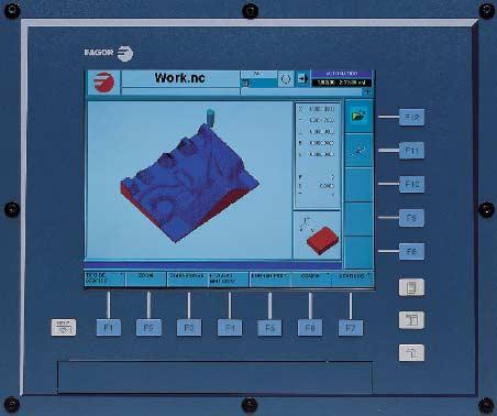
10 1 CNC structure CPU (Central Unit) / Monitor The central unit is located on the rear of the monitor. There are 10 and 12 LCD monitors depending on the type of central unit. PCI PC104 CNC structure Dimensions (without monitor) (294 x 206 x 117.5) mm (11.57 x 8.11 x 4.62) inch (376.5 x 280 x ) mm (14.82 x x 4.79) inch Monitor size 12 LCD 10 LCD 12 LCD Without monitor HD Yes Yes Compact flash No Option Battery for emergency turn-off No Option Ethernet T base 10/100Mhz T base 10/100Mhz Modem / Fax 56K 56K USB ports No 2 Battery of the CMOS CR2032 CR2450 (access from the outside) The PC104 central unit is available without monitor, thus being possible to install it remotely. A standard off-the-shelf VGA monitor may be used. In this case, the maximum cable length is 10 meters. Keyboard and operator panel The keyboard and the operator panel may go separately or integrated into a single keyboard-operator-panel. The keyboard and the operator panel may also be integrated into the monitor. Peripherals Such as floppy disk drives, CD-ROM drive or mouse. They may be connected to the CNC through specific cables. 2
11 1.1 Possible configurations Basic hardware The hardware elements described in this manual are identified as follows. PCI PC104 LCD-10 LCD-10K LCD-12 OP-Panel-H/E Key Board Panel H Jog Panel PCI central unit. PC104 central unit. 10 LCD monitor. 10 LCD monitor with integrated keyboard and operator panel. 12 LCD monitor. Keyboard with integrated operator panel. Available either with an electronic handwheel (OP-Panel-H) or with an emergency stop button (OP-Panel-E). Keyboard. Operator panel. CNC structure Additional hardware E-stop + handwheel unit. Mouse unit. Floppy disk drive. Emergency battery Optional when having a PC104 central unit. It ensures proper operation of the CNC when there is a mains outage. In those cases, the CNC stops the machine and the CNC turns off in a controlled manner. 3
12 (UC-PCI) + (LCD-12) + (OP-Panel-H/E) The central unit offers access from the front panel to the floppy disk drive and to the connectors for the keyboard and the mouse through a PS-2 connector. The keyboard and the operator panel are a single module. The operator panel may have either an emergency button (E-stop) or a handwheel. CNC structure (UC-PCI) + (LCD-12) OP-Panel-H/E For further information about the central unit and the monitor, refer to section "3 PCI central unit." For further information about the keyboard, refer to section "8 Set of keyboard and operator panel (OP-Panel-H/E)". Basic connection The CAN bus is used to connect the various elements that make up the CNC. The Sercos bus is used to communicate with FAGOR drives. It is also possible to communicate with analog drives using the CAN bus. Remember that the ground terminals of all the elements making up the system must be connected to a single ground point. 4
13 (UC-PC104) + (LCD-12) + (OP-Panel-H/E) The keyboard and the operator panel are a single module. The operator panel may have either an emergency button (E-stop) or a handwheel. (UC-PC104) + (LCD-12) OP-Panel-H/E CNC structure For further information about the central unit and the monitor, refer to section "7 PC-104 central unit with LCD-12 monitor" For further information about the keyboard and the operator panel, refer to section "8 Set of keyboard and operator panel (OP-Panel-H/E)". Basic connection The CAN bus is used to connect the various elements that make up the CNC. The Sercos bus is used to communicate with FAGOR drives. It is also possible to communicate with analog drives using the CAN bus. Remember that the ground terminals of all the elements making up the system must be connected to a single ground point. 5
14 (UC-PC104) + (LCD-10) + (Key Board Panel H) + (Jog Panel) The keyboard and the operator panel are independent modules. CNC structure (UC-PC104) + (LCD-10) Key Board Panel H Jog Panel For further information about the central unit and the monitor, refer to section "5 PC-104 central unit with LCD-10 monitor" For further information about the keyboard, refer to section "9 Keyboard (Key Board Panel H)". For further information about the operator panel, refer to section "10 Operator panel (Jog panel)". Basic connection The keyboard is connected through the PS-2 port. The CAN bus is used to connect the rest of the elements that configure the CNC. The Sercos bus is used to communicate with FAGOR drives. It is also possible to communicate with analog drives using the CAN bus. Remember that the ground terminals of all the elements making up the system must be connected to a single ground point. 6
15 (UC-PC104) + (LCD-10K) The keyboard and the operator panel are integrated into the monitor. (UC-PC104) + (LCD-10K) For further information about the central unit and the monitor, refer to section "6 PC-104 central unit with LCD-10K monitor" CNC structure Basic connection The CAN bus is used to connect the various elements that make up the CNC. The Sercos bus is used to communicate with FAGOR drives. It is also possible to communicate with analog drives using the CAN bus. Remember that the ground terminals of all the elements making up the system must be connected to a single ground point. 7
16 1.2 Additional hardware Emergency battery. See "14 Emergency battery" CNC structure Emergency button and handwheel. See "11 Handwheel + E-stop button module". Mouse. See "12 Mouse module". Floppy disk drive. See "13 Floppy disk drive.". 8
17 2 Heat dissipation. Central unit (cpu) enclosure The working temperature of the central unit enclosure must not exceed 45ºC (113ºF). To ensure that it does not exceed this temperature, the enclosure must meet the following requirements: Have enough surface inside to evacuate the heat generated inside and keep the ambient conditions within the working temperature range. Respect the minimum distances recommended between the enclosure walls and the central unit. See "3.3 PCI. Characteristics of the enclosure". See "4.3 PC104. Characteristics of the enclosure". Calculation of the surface needed for heat dissipation The expressions have been obtained for an enclosure having a 2 mm wall and made out of aluminum. When using internal ventilation, the fan must be located 30 mm off the bottom. To calculate the total surface required for the enclosure, in order to dissipate the heat generated in it, the following data must be considered. Ti A Heat dissipation. Central unit (cpu) enclosure Ta Q P 30mm A (m 2 ) Required total surface. P (W) Total power dissipated by all the elements that generate heat inside the enclosure, including the power supply and the fan, if there is one. Ta (ºC) Ambient temperature (outside the enclosure). Ti (ºC) Temperature inside the enclosure. t (ºC) Temperature difference (Ti-Ta). Q (m 3 /h) Air flow supplied by the fan, if there is one. Dissipating surface Only surfaces dissipating heat by convection will be considered, the top and the rear of the enclosure. The rest of the surfaces are not to be considered when calculating the total surface. Power dissipated by the CNC The maximum power dissipated by the central unit PCI and PC104 are 100 watts. 9
18 Heat dissipation by natural convection Ta Ti A Unpainted surface. A = P T P Surface with smooth metallic enamel. Heat dissipation. Central unit (cpu) enclosure A = P ,7 T Heat dissipation by forced convection with internal fan Fan whose air flow Q = 13.6 m 3 /h facing down. Unpainted surface. Ta A P Ti A = ,6 T P Surface with smooth metallic enamel. A = P ,6 T Fan whose air flow Q = 13.6 m 3 /h facing up. Ta Ti A Unpainted surface. A = P ,8 T P Fan whose air flow Q = 30 m 3 /h facing down. Ta Ti A Unpainted surface. A = P ,75 T P Surface with smooth metallic enamel. A = P ,1 T 10
19 Fan whose air flow Q = 102 m 3 /h facing down. Ta Ti A Unpainted surface. A = P ,5 T P Surface with smooth metallic enamel. A = P ,8 T Heat dissipation by air flow to the outside using a fan Heat dissipation by forced convection with hot air flow to the outside using a fan and ambient air intake through the holes located at the bottom of the enclosure. For this case, the volume of air flow is calculated necessary to evacuate the heat generated inside the enclosure. The fan's air flow is calculated according to the power dissipated by the CNC and the fan itself as well as the inside and outside temperatures. Heat dissipation. Central unit (cpu) enclosure Ø6 40 Unpainted surface. 3,8 P V = T 40 Bear in mind that this air flow through the unit extracts hot air to the outside, but it allows dirt into the enclosure. Thus, a filter should be installed to maintain the ambient conditions allowed. 11
20 3 PCI central unit. PCI central unit. Monitor 12.1 LCD monitor (18-bit color). Resolution 800x600. Description It has the following elements: 3.5 floppy disk drive. It may be accessed from the front panel for peripherals. CAN and Sercos communications board. Board for connecting to Ethernet and peripherals (PC-compatible keyboard, mouse with PS-2 connector and PC monitor). It is possible to connect a PC-compatible keyboard or mouse using a PS-2 connector from the front panel. Power supply Universal AC power supply. Connect it through a separate shielded 110 VA transformer with an output voltage between 84Vac and 264 Vac. 12
21 3.1 PCI. Dimensions PCI central unit. Panel dimensions mm. inch a b c 124, d 156, Location of the holes mm. inch Da Db Dc Ø
22 3.2 PCI. Technical characteristics Electrical characteristics PCI central unit. Universal AC power supply. Connect it through a separate shielded 110 VA transformer with an output voltage between 84Vac and 264 Vac. Mains frequency: Hz ±1% and ±2% for very short periods. Power outages: Meets the EN regulation. It can withstand microsurges of up to 10 milliseconds at 50 Hz starting at 0º and 180º (two polarities, positive and negative). Harmonic distortion: Less than 10% of the total rms voltage between conductors under power (sum of the 2nd and 5th harmonics). Vibrations Operating: Hz with an amplitude of mm at constant speed Hz with 0.5g of constant acceleration. Packaging: Meets EN standard Free fall packaged according to Fagor regulations: 0.5 meters. Ambient conditions Relative humidity: 5-85% without condensation. Work temperature: 5-40ºC with an average lower than 35ºC. Storage temperature: Between -25ºC and +70ºC (77ºF and 158ºF). Maximum work altitude: Meets the IEC standard. Degree of protection Front panel: It meets the protection standard IP54. Rear panel: It meets the protection standard IP 2X. Accessible parts inside: It meets the protection standard IP 1X. The machine manufacturer must comply with the EN (IEC-204-1) regulation regarding electrical shocks in case of defective input/output pins with external power supply when not plugging this connector before turning the power supply on. This unit MUST NOT be opened by unauthorized personnel. Only personnel authorized by Fagor Automation may manipulate the inside of this module. 14
23 3.3 PCI. Characteristics of the enclosure Securing the unit The central unit must be installed in a proper enclosure that may be located on the machine or on an external support. To insert the unit into the enclosure, it must have a big enough hole to allow to insert it easily, without obstacles and without forcing the unit. Once the unit has been inserted into the enclosure, secure it from the outside with the screws. To properly secure it, use the mounting holes on the front panel of the unit. PCI central unit. Location of the holes mm. inch Da Db Enclosure dimensions mm. inch W H
24 Characteristics of the enclosure The working temperature of the enclosure must not exceed 45ºC (113ºF). To ensure that it does not exceed this temperature, respect the recommended minimum gap between the sides of the enclosure and the central unit. PCI central unit. mm. inch A B C D E To ensure the required ambient conditions, the enclosure must have an air input next to the cables and an air output next to the fan. In this case, install fans to ventilate the enclosure and keep the temperature within the allowed limits. Keep the enclosure clean. Anti-dust filters should be installed at the air inputs and outputs. Room reserved for cables Reserve some room for the cables in the connector area. This space makes it possible to bend the cables for the CPU connection with the recommended bending radius. Special care must be taken with the Sercos connection because bending the optic fiber too much could break it. 16
25 3.4 PCI. Elements (connectors) Front connectors The little compartment under the screen has the following elements. A B C D A. Enclosure reserved for optional devices: PCMCIA card, CD ROM, Floppy disk, etc. B. 3½" floppy disk drive. C. Connector for a PC-compatible keyboard. D. Connector for a serial mouse with a PS-2 connector. PCI central unit. Side connectors A. Communications board See "3.5 PCI. CAN and Sercos communications board.". B. Relay for the emergency chain. See "3.7 PCI. Relay for the emergency chain". C. CPU board. See "3.6 PCI. CPU board connectors". D. Power switch. E. Mains connection. F. Ground connection. Rear connectors A. Connector for the CPU keys with the CNC keyboard. Maximum cable length is 1 meter. 17
26 3.5 PCI. CAN and Sercos communications board. CAN communications board PCI central unit ABCDEF0 LINE TERM ISO GND CAN L SHIELD CAN H SHIELD ADDRESS It is used to connect the various elements that make up the system. Keyboard and operator panel Remote modules. For further information on how to configure the connection of the elements to the CAN bus, refer to section "16 CAN connection". 4 CAN and Sercos communications board. It is used to communicate with Fagor digital drives. IN OUT For further information on how to configure the connection of the elements to the Sercos bus, refer to section "17 Sercos Connection" ABCDEF0 ADDRESS 18
27 3.6 PCI. CPU board connectors The CPU board allows connecting the unit to an Ethernet network. It also allows connecting the following peripherals to the unit. A. To connect the CNC to an Ethernet network. B. PC monitor. C. PC-compatible keyboard. The mouse and the PC keyboard may also be connected from the front of the unit. PCI central unit. 19
28 3.7 PCI. Relay for the emergency chain a b It is a normally open contact that closes when the CNC is turned on and it is running properly. It opens when turning the CNC off or due to an internal failure This relay withstands up to 1A at 24V. PCI central unit. 20
29 4 PC104 central unit. General description MONITOR -10.4" MONITOR " PC104 central unit. General description Monitor The following monitors are available LCD monitor (18-bit color). Resolution 800x LCD monitor (18-bit color). Resolution 800x600. Optionally, it is also available without monitor, thus being possible to install it remotely. External connection This base unit has the following elements: CAN and Sercos communications board. Connection to Ethernet and standard peripherals (PC-compatible keyboard, mouse with PS-2 connector and VGA monitor). Two serial communication port (COM1, COM2). A parallel communications port (LPT1). Connector for FLOPPY disk drive. Connector for IDE device (CD-ROM, DVD, hard disk, etc). Power supply Universal DC power supply. Power with a 24 Vdc ±10% and 3.5A power supply. 21
30 Hardware configuration Processor RAM memory HD Compact flash Pentium III 800 Mhz 256 Mb Yes Optional PC104 central unit. General description Monitor Ethernet Modem / Fax Battery of the CMOS 10.4 LCD 10.4 LCD (with keyboard) 12.1 LCD T base 10/100Mhz 56K CR2450 (access from the outside) 22
31 4.1 PC104. Dimensions of the central unit without monitor a c Db Da Dimensions mm. inch a b Location of the holes mm. inch Da PC104 central unit. General description b Db c Ø
32 4.2 PC104. Technical characteristics Electrical characteristics Universal DC power supply. Power with a 24 Vdc ±10% and 3.5A power supply. Current peak of 51.9 A on power-up. PC104 central unit. General description Protection against over-voltage and reverse voltage. It has a fuse that may be accessed from the outside as protection against over-voltage. Greater than 36 Vdc or 25 Vac. It is also protected against reverse connection of the power supply, preventing it from starting up. Protection against over-current. An over-current activates the safety device inside the power supply. The central unit has an LED that turns on when this device is active. To reactivate the power supply after an over-current, just press the button for it. If the led comes back on, call the Technical Service. The power supply may be reactivated by disconnecting it for 30 seconds. Power outages. Meets the EN regulation. It can withstand microsurges of up to 10 milliseconds Vibrations Operating: Hz with an amplitude of mm at constant speed Hz with 0.5g of constant acceleration. Packaging: Meets EN standard. Free fall packaged according to Fagor regulations: 0.5 meters. 24
33 Ambient conditions Relative humidity: 5-85% without condensation. Work temperature: 5-40ºC with an average lower than 35ºC. Storage temperature: Between -25ºC and +70ºC (77ºF and 158ºF). Maximum work altitude: Meets the IEC standard. Degree of protection Front panel: It meets the protection standard IP54. Rear panel: It meets the protection standard IP 2X. Accessible parts inside: It meets the protection standard IP 1X. The machine manufacturer must comply with the EN (IEC-204-1) regulation regarding electrical shocks in case of defective input/output pins with external power supply when not plugging this connector before turning the power supply on. This unit MUST NOT be opened by unauthorized personnel. Only personnel authorized by Fagor Automation may manipulate the inside of this module. PC104 central unit. General description 25
34 4.3 PC104. Characteristics of the enclosure Securing the unit The central unit must be installed in a proper enclosure that may be located on the machine or on an external support. To insert the unit into the enclosure, it must have a big enough hole to allow to insert it easily, without obstacles and without forcing the unit. PC104 central unit. General description Characteristics of the enclosure Once the unit has been inserted into the enclosure, secure it from the outside with the screws. To properly secure it, use the mounting holes on the front panel of the unit. The dimensions of the enclosure depend on the type of monitor that comes with the central unit. The working temperature of the enclosure must not exceed 45ºC (113ºF). To ensure that it does not exceed this temperature, respect the recommended minimum gap between the sides of the enclosure and the central unit. mm. inch A B C D E To ensure the required ambient conditions, the enclosure must have an air input next to the cables and an air output next to the fan. In this case, install fans to ventilate the enclosure and keep the temperature within the allowed limits. Keep the enclosure clean. Anti-dust filters should be installed at the air inputs and outputs. Room reserved for cables Reserve some room for the cables in the connector area. This space makes it possible to bend the cables for the CPU connection with the recommended bending radius. Special care must be taken with the Sercos connection because bending the optic fiber too much could break it. 26
35 4.4 PC104. Elements (connectors) Rear connectors SL1 SL2 IOIO X5 X7 L1 PC104 central unit. General description X8 X9 X10 F5A X6 A B SL1 SL2 IOIO X5 X6 X7 X8 X9 X10 Connector for floppy disk drive. To connect a floppy disk drive to the central unit. See "13 Floppy disk drive.". Connector for IDE device (CD-ROM). Serial line (COM1). VGA output. Parallel port (LPT1). Serial line (COM2). Emergency battery. Output to supply voltage to the operator panel. Universal DC power supply. For further information on how to connect the power supply, see "4.5 PC104. Power supply and battery" For further information about the electrical characteristics of the unit, see "4.2 PC104. Technical characteristics". 27
36 F5A L1 Over-voltage protection fuse. It is possible to connect an external battery to the central unit to ensure that the CNC will keep running if there is a power outage. See "4.5 PC104. Power supply and battery". Indicator for the proper operation of the COMPCI. Green LED blinks if the COMPCI is working fine. PC104 central unit. General description Side connectors Other elements A.Ground terminal. All ground terminals of the machine must be connected to this terminal. B.Over-voltage indicator on the power supply. It has a red LED and a push-button. The LED turns on when there is over-current at the power supply. The button may be used to reactivate the power supply after an over-current. For further information about the electrical characteristics of the unit, see "4.2 PC104. Technical characteristics". C X1 X2 X4 X3 X1 X2 - X3 X4 Relay for the emergency chain. See "4.9 PC104. Relay for the emergency chain". Communications board See "4.6 PC104. CAN and Sercos communications board.". Connection of the CPU keys with the CNC keyboard. Maximum cable length is 1 meter. Other elements C.CPU board for connecting peripherals. See "4.7 PC104. CPU board connectors". 28
37 4.5 PC104. Power supply and battery The central unit is powered by an external DC power supply. See "4.2 PC104. Technical characteristics". It is also possible to connect an external battery that ensures the proper operation of the unit under AC power outages. When that happens, the central unit responds as follows: If the supply is interrupted for less than 2 seconds. The screens shows the corresponding warning and the system recovers fine. If the supply is interrupted for more than 2 seconds. After the 2 seconds, the screen shows the corresponding error and it initiates the automatic turn-off sequence. PC104 central unit. General description X8 X9 X10 F5A X8 X9 X10 F5A Emergency battery. 24V output to supply voltage to the operator panel. Power supply. Fuse. 29
38 Connector X10: Universal 24V power supply Consult the electrical characteristics of the central unit before connecting the power supply. See "4.2 PC104. Technical characteristics". 3-pin male Phoenix connector (7.62 mm pitch). PC104 central unit. General description + 24V GND Chassis + 24V GND Chassis Fuse It has a fuse that may be accessed from the outside to protect against over-voltage (greater than 36 Vdc or 25 Vac). Connector X9: Power supply for the operator panel 3-pin male Phoenix minicombicon connector (3.5 mm pitch). This connector offers the possibility to supply voltage from the central unit to the operator panel. It is mainly oriented to those configurations where the operator panel is integrated into the monitor (e.g. LCD-10K) or close to it. Connector X8: Power supply with a battery. 5-pin male Phoenix minicombicon connector (3.5 mm pitch). Signal Vbat - / Vbat + Chassis Vch - / Vch + Description Central unit powered by the battery. System ground connection Charge the battery. Vbat - Vbat + Chassis Vch + Vch - 30
39 4.6 PC104. CAN and Sercos communications board. CAN communications board ABCDEF0 LINE TERM ISO GND CAN L SHIELD CAN H SHIELD ADDRESS It is used to connect the various elements that make up the system. Keyboard and operator panel Remote modules. For further information on how to configure the connection of the elements to the CAN bus, refer to section "16 CAN connection". CAN and Sercos communications board. PC104 central unit. General description It is used to communicate with Fagor digital drives. IN OUT For further information on how to configure the connection of the elements to the Sercos bus, refer to section "17 Sercos Connection" ABCDEF0 ADDRESS 31
40 4.7 PC104. CPU board connectors PC104 central unit. General description A B C D E With the CPU board, it is possible to connect the most common PC peripherals, even a modem, to the CNC. It also has an Ethernet connector to integrate the CNC into a network. A. Ethernet connector. B. Mouse with PS-2 connector. C. PC-compatible keyboard. D. USB ports. E. Modem. 32
41 4.8 PC104. Connectors for a floppy disk drive or IDE Connector SL1. Connection of a floppy disk drive SL1 For connecting a floppy disk drive to the central unit using the floppy disk interface. See "13 Floppy disk drive.". +5V GND GND +12V To access the connectors, remove the connector protecting plate. The compartment has these two connectors. Connector for the data cable. Male Header type connector with 2x17 pins and 1 inch x 1 inch (25.4 mm x 25.4 mm) pitch. Connector for the power cable of the peripheral device. Molex 5273 male connector-na with 4 pins and 2.96 mm pitch. PC104 central unit. General description Connector SL2. Connection of an IDE device SL2 For connecting a CD-ROM drive or another device that uses an IDE interface to the central unit. +5V GND GND +12V To access the connectors, remove the connector protecting plate. The compartment has these two connectors. Connector for the data cable. Male Header type connector with 2x20 pins and 1 inch x 1 inch (25.4 mm x 25.4 mm) pitch. Connector for the power cable of the peripheral device. Molex 5273 male connector-na with 4 pins and 2.96 mm pitch. 33
42 4.9 PC104. Relay for the emergency chain a b c They are two normally open contacts that close when the CNC is turned on and it is running properly. They open again when turning the CNC off or due to an internal failure These relays withstand up to 1A at 24V. d PC104 central unit. General description 34
43 5 PC-104 central unit with LCD-10 monitor This chapter shows specific data for the central unit with this type of monitor. For further information on the central unit, refer to section "4 PC104 central unit. General description". Before installing the central unit or manipulating the connectors, carefully read the information detailed in section "4 PC104 central unit. General description" of this manual. PC-104 central unit with LCD-10 monitor Type of monitor 10.4 LCD monitor (18-bit color). Resolution 800x
44 5.1 LCD-10. Dimensions c a PC-104 central unit with LCD-10 monitor d Db Dc Dimensions Dc Da Da Location of the holes b mm. inch mm. inch a Da b Db c Dc d Ø
45 5.2 LCD-10. Characteristics of the enclosure Securing the unit To properly secure it, use the mounting holes on the front panel of the unit. PC-104 central unit with LCD-10 monitor Location of the holes mm. inch Da Db Enclosure dimensions mm. inch W H Characteristics of the enclosure The working temperature of the enclosure must not exceed 45ºC (113ºF). To ensure that it does not exceed this temperature, respect the recommended minimum gap between the sides of the enclosure and the central unit. See "4.3 PC104. Characteristics of the enclosure". 37
46 6 PC-104 central unit with LCD-10K monitor This chapter shows specific data for the central unit with this type of monitor. For further information on the central unit, refer to section "4 PC104 central unit. General description". Before installing the central unit or manipulating the connectors, carefully read the information detailed in section "4 PC104 central unit. General description" of this manual. PC-104 central unit with LCD-10K monitor Type of monitor 10.4 LCD monitor (18-bit color). Resolution 800x600. The monitor has an alpha-numeric keyboard and an operator panel integrated into it. 38
47 6.1 LCD-10K. Dimensions PC-104 central unit with LCD-10K monitor Panel dimensions mm. inch a b c e f 51 2 g h i j k Location of the holes mm. inch Da Db Dc Ø
48 6.2 LCD-10K. Characteristics of the enclosure Securing the unit To properly secure it, use the mounting holes on the front panel of the unit. PC-104 central unit with LCD-10K monitor Location of the holes mm. inch Da Db Enclosure dimensions mm. inch W H Characteristics of the enclosure The working temperature of the enclosure must not exceed 45ºC (113ºF). To ensure that it does not exceed this temperature, respect the recommended minimum gap between the sides of the enclosure and the central unit. See "4.3 PC104. Characteristics of the enclosure". 40
49 6.3 LCD-10K. Elements (connectors) We now describe the specific connectors for this type of monitor: For further information on the connectors of the central unit, refer to section "4.4 PC104. Elements (connectors)". Rear connectors Besides the connectors of the central unit, the connectors of the operator panel are in the rear. X11 CAN CONFIG NODE RT X12 X13 X ABCDEF0 OK ERR PWR 0 1 PC-104 central unit with LCD-10K monitor 4 X11 CAN CONFIG NODE OK ERR PWR RT X12 X13 X14 Handwheel connection. CAN bus configuration. Operator panel address selector on the CAN bus. Green LED. It turns on when the bus is working fine. Red LED. It turns on when there is an error at the bus. Red LED. It turns on when the operator panel is under voltage. Line termination switch for the CAN bus. Connector for the CAN bus. Connector for the CAN bus. Power supply. For further information on how to connect and configure the CAN bus, see section "16 CAN connection" of this manual. 41
50 Connector X11: Handwheel connection 10-pin male Phoenix minicombicon connector (3.5 mm pitch). PC-104 central unit with LCD-10K monitor + 24V GND Chassis GND MPG1-A MPG1-B MPG2-A MPG2-B MPG3-A MPG3-B +5 Vdc Connector X14: Power supply 3-pin male Phoenix minicombicon connector (3.5 mm pitch). 42
51 7 PC-104 central unit with LCD-12 monitor This chapter shows specific data for the central unit with this type of monitor. For further information on the central unit, refer to section "4 PC104 central unit. General description". Before installing the central unit or manipulating the connectors, carefully read the information detailed in section "4 PC104 central unit. General description" of this manual. PC-104 central unit with LCD-12 monitor Type of monitor 12.1 LCD monitor (18-bit color). Resolution 800x
52 7.1 LCD-12. Dimensions c a f Db PC-104 central unit with LCD-12 monitor d e Db Dc Dc Da Da b g h Dimensions mm. inch a b c d e f g h Location of the holes mm. inch Da Db Dc Ø
53 7.2 LCD-12. Characteristics of the enclosure Securing the unit To properly secure it, use the mounting holes on the front panel of the unit. PC-104 central unit with LCD-12 monitor Location of the holes mm. inch Da Db Enclosure dimensions mm. inch W H Characteristics of the enclosure The working temperature of the enclosure must not exceed 45ºC (113ºF). To ensure that it does not exceed this temperature, respect the recommended minimum gap between the sides of the enclosure and the central unit. See "4.3 PC104. Characteristics of the enclosure". 45
54 7.3 LCD-12. Elements (connectors) We now describe the specific connectors for this type of monitor: For further information on the connectors of the central unit, refer to section "4.4 PC104. Elements (connectors)". Front connectors PC-104 central unit with LCD-12 monitor The little compartment under the screen has the following elements: A B C D A.Enclosure reserved for optional devices: PCMCIA card, CD ROM, Floppy disk, etc. B.3½" floppy disk drive. C.Connector for a PC-compatible keyboard. D.Connector for a serial mouse with a PS-2 connector. 46
55 8 Set of keyboard and operator panel (OP-Panel-H/E) Hardware configuration Set of alpha-numeric QWERTY keyboard with integrated operator panel. The operator panel has either an emergency button (E-stop) or a handwheel. Description Set of keyboard and operator panel (OP-Panel-H/E) 24 Vdc universal power supply. Connection to the central unit through CAN bus. Electronic handwheels. Possibility to connect up to three handwheels with A and B signals (5 Vdc TTL). For further information, refer to section "8.4 Elements". 47
56 8.1 Dimensions Set of keyboard and operator panel (OP-Panel-H/E) Dimensions mm. inch a b c Location of the holes mm. inch Da Db Dc Ø
57 8.2 Technical characteristics Degree of protection It meets the protection standard IP54. The machine manufacturer must comply with the EN (IEC-204-1) regulation regarding electrical shocks in case of defective input/output pins with external power supply when not plugging this connector before turning the power supply on. This unit MUST NOT be opened by unauthorized personnel. Only personnel authorized by Fagor Automation may manipulate the inside of this module. Set of keyboard and operator panel (OP-Panel-H/E) 49
58 8.3 Securing characteristics Set of keyboard and operator panel (OP-Panel-H/E) Location of the holes mm. inch Da Db Enclosure dimensions mm. inch W H
59 8.4 Elements The connectors are in the rear. Set of keyboard and operator panel (OP-Panel-H/E) A. Connection of the keys of the central unit. Maximum cable length is 1 meter. B. Buzzer. C. Keyboard address selector on the CAN bus. D. Line termination switch for the CAN bus. E. Handwheel connection. Up to 3 handwheels are possible (MPG1, MPG2 and MPG3) with 5 Vdc A and B TTL signals. F. Connector for the CAN bus. G.Connector for the CAN bus. H. Connector to power the keyboard with 24 Vdc. I. Ground connection. For further information on how to connect to the CAN bus, see section "16 CAN connection" of this manual. 51
60 9 Keyboard (Key Board Panel H) ESC CAPS A B C F G INS Home SHIFT H I J K M SUP End ENTER CTRL P R S T U RECALL Keyboard (Key Board Panel H) ALT V Description W X Y Z Connection to the central unit through PS-2 connector. For further information about the connectors, refer to section "9.4 Elements". 0 SPACE 52
61 9.1 Dimensions Dimensions mm. inch a b c Location of the holes mm. inch Da Db Ø Keyboard (Key Board Panel H) 53
62 9.2 Technical characteristics Degree of protection It meets the protection standard IP54. Keyboard (Key Board Panel H) The machine manufacturer must comply with the EN (IEC-204-1) regulation regarding electrical shocks in case of defective input/output pins with external power supply when not plugging this connector before turning the power supply on. This unit MUST NOT be opened by unauthorized personnel. Only personnel authorized by Fagor Automation may manipulate the inside of this module. 54
63 9.3 Securing characteristics Da Location of the holes mm. inch Da Db Db Enclosure dimensions mm. inch W H Keyboard (Key Board Panel H) 55
64 9.4 Elements The connectors are in the rear. A B C Keyboard (Key Board Panel H) A.Connection of the keys of the central unit. Maximum cable length is 1 meter. B.PS-2 connector to connect the keyboard to the central unit. C.Ground terminal. All ground terminals of the machine must be connected to this terminal. 56
65 10 Operator panel (Jog panel) X Y Z Description ZERO 24 Vdc universal power supply. Connection to the central unit through CAN bus. Electronic handwheels. Possibility to connect up to three handwheels with A and B signals (5 Vdc TTL). RESET Operator panel (Jog panel) For further information about the connectors, refer to section "10.4 Elements". 57
66 10.1 Dimensions Operator panel (Jog panel) Dimensions mm. inch a b c Location of the holes mm. inch Da Db Ø
67 10.2 Technical characteristics Degree of protection It meets the protection standard IP54. The machine manufacturer must comply with the EN (IEC-204-1) regulation regarding electrical shocks in case of defective input/output pins with external power supply when not plugging this connector before turning the power supply on. This unit MUST NOT be opened by unauthorized personnel. Only personnel authorized by Fagor Automation may manipulate the inside of this module. Operator panel (Jog panel) 59
68 10.3 Securing characteristics Da H W Operator panel (Jog panel) Location of the holes mm. inch Da Db Db Enclosure dimensions mm. inch W H
69 10.4 Elements The connectors are in the rear. Chassis GND + 24 Vdc ISO GND CAN L SHIELD CAN H SHIELD ISO GND CAN L SHIELD CAN H SHIELD 5 Vdc MPG3-B MPG3-A MPG2-B MPG2-A MPG1-B MPG1-A GND 0 1 B C D E F G H I J K Operator panel (Jog panel) A A. Ground terminal. All ground terminals of the machine must be connected to this terminal. B. Connector to power the keyboard with 24 Vdc. C. Connector for the CAN bus. D. Connector for the CAN bus. E. Line termination switch for the CAN bus. F. Red LED. It turns on when the operator panel is under voltage. G.Red LED. It turns on when there is an error at the CAN bus. H. Green LED. It turns on when the CAN bus is working fine. I. Operator panel address selector on the CAN bus. J. CAN bus configuration. K. Connector for the handwheels. Up to 3 handwheels are possible (MPG1, MPG2 and MPG3) with 5 Vdc A and B TTL signals. For further information on how to connect and configure the CAN bus, see section "16 CAN connection" of this manual. 61
70 11 Handwheel + E-stop button module Set of handwheel and emergency button to connect to the PC104 central unit. Handwheel + E-stop button module 62
71 11.1 Handwheel + E-stop button module dimensions Dimensions mm. inch a b c Location of the holes mm. inch Da Db Ø Handwheel + E-stop button module 63
72 12 Mouse module Flat mouse to be connected to the PC104 central unit. Mouse module External connection The mouse is connected to the central unit through the PS-2 connector. 64
73 12.1 Mouse dimensions Mouse module Dimensions mm. inch a b c Location of the holes mm. inch Da Db Ø
74 13 Floppy disk drive. Floppy disk drive to be connected to the PC104 central unit. It has two USB connection points. Floppy disk drive. External connection The following elements are in the rear: C A B A.Power supply. B.Connector for the data cable. C.USB connector. 66
75 13.1 Floppy disk drive dimensions Dimensions mm. inch a b c Location of the holes mm. inch Da Db Ø Floppy disk drive. 67
76 13.2 Floppy disk drive installation Floppy disk drive. B A Connecting the floppy disk drive to the central unit requires a power cable, a 34-pin data cable and a standard USB cable with Type-A connectors at both ends. 1. Turn the central unit off and unplug the power cable. 2. At the central unit, remove the plate protecting the floppy disk drive connector. The floppy disk drive is connected through two connectors. A. 34-pin connector for the data cable. B. Connector for the power cable of the floppy disk drive. 3. Connect the data cable between the floppy disk drive and the central unit. 4. Connect the power cable between the floppy disk drive and the central unit. 5. Connect the USB cable between thefloppy disk drive and the central unit. 6. Secure the floppy disk drive in its compartment. To properly secure it, use the mounting holes on the front panel of the unit. 7. Plug the general power cable of the central unit. 68
77 14 Emergency battery It is in charge of supplying power to the central unit in case of a AC power outage. Emergency battery Characteristics The battery provides an autonomy of 20 minutes after being charged for 35 hours. 69
78 14.1 Battery dimensions Emergency battery Dimensions mm. inch a b c d e f Location of the holes mm. inch Da Ø
79 14.2 Elements (connectors) It has a single connector to charge the battery and supply the system when necessary. 5-pin male Phoenix minicombicon connector (3.5 mm pitch). Vbat - Vbat + Chassis Vch + Vch - Signal Vbat - / Vbat + Chassis Vch - / Vch + Description Central unit powered by the battery. System ground connection Charge the battery. The LED next to the connector blinks while the battery is being charged and it stays on when the battery is charged. Emergency battery 71
80 15 Remote modules They are distributed in groups. Each group may have up to 5 modules depending on consumption. Place the modules on 2 profiles, according to the UNE standard, with 2 securing ends, one at each end of the group. They help securing the modules besides maintaining the right gap between the profiles. Remote modules Elements There are full-size and half-size modules. Full-size modules fill out the whole box (Power Supply, Counter). Half-size modules occupy half the box (Analog Output, Analog Input, Digital Output, Digital Input). All types of possible combinations are supplied with half-size modules, even units with a single half-size module (the other half will be a cover). The mounting order to be followed from left to right is: Power Supply. Counters. Analog outputs. Half size. Analog inputs. Half size. Digital outputs. Half size. Digital inputs. Half size. 72
81 Dimensions Always leave a 140 mm gap under the modules for ventilation and later handling. Remote modules Connection of the modules The modules of the group are connected as follows: A. For ground connection. B. Ribbon cable to interconnect the modules. C. Securing ends. Each group is connected to the system (CPU, Keyboard, etc.) through the CAN bus as described later on. 73
82 15.1 Consumption of the remote modules The power supply is in charge of supplying to the rest of the modules through +5V and ±18V and managing the internal bus of the group. The total consumption of the group depends on the configuration of the modules. 5V ±18V (DI) Digital inputs 0.40 watts Remote modules (DO) Digital outputs 0.65 watts (AI) Analog inputs 0.3 watts 1.8 watts (AO) Analog outputs 0.35 watts 3.4 watts (CT) Counters 1.75 watts (CPU) CPU-CAN 0.6 watts The consumption of the CPU-CAN is added to each module of the configuration. When mounting two half-size modules together (in the same box), the consumption of the CPU-CAN must only be added once. The total consumption of the group must not exceed the following maximums: For +5V, a maximum consumption of 10 watts. For ±18V, a maximum consumption of 7.2 watts. If any of them is exceeded, double the group. Use two power supplies and distribute the modules. Example: Modules 5V ±18V (CT) + (CPU) 1,75 + 0, (DI) + (DI) +(CPU) 0,4 + 0,4 + 0, (DO) + (DO) + (CPU) 0,65 + 0,65 + 0, (AO) + (CPU) 0,35 + 0,6 3,4 Total consumption 6,60 watts 3.4 watts 74
83 15.2 Power Supply It must be present in all configurations (1 per group). It must be powered at 24 Vdc and connected to the system CAN bus. Remote modules X1 Chassis For system ground connection. X1 +24V / GND For the 24 Vdc power supply. X1 System Ready For the emergency chain from the electrical cabinet. It is an internal contact that closes when the group is ready. Over voltage +5V System Ready It has a push-button and a red LED that turns on when activating the internal safety device of the +5V power supply. Use the push-button to reactivate the power supply. If the LED comes back on, call the Technical Service. Green LED that blinks when the group is ready. +5V over-current Red LED that comes on when the +5V power supply is demanded the maximum current. +5 error Red LED that turns on when the power supply is not capable of supplying the 5 Vdc due to over-current. Remove some load or duplicate the group. Power Green LED that comes on when the +5 V is working properly. 75
CNC. Remote modules. (Ref: 1309)
") CNC 8065 Remote modules (Ref: 309) MACHINE SAFETY It is up to the machine manufacturer to make sure that the safety of the machine is enabled in order to prevent personal injury and damage to the CNC or
CNC 8065 Remote modules (Ref: 309) MACHINE SAFETY It is up to the machine manufacturer to make sure that the safety of the machine is enabled in order to prevent personal injury and damage to the CNC or
CNC. Hardware configuration. (Ref: 1709)
") CNC 8070 Hardware configuration. (Ref: 1709) TRANSLATION OF THE ORIGINAL MANUAL This manual is a translation of the original manual. This manual, as well as the documents derived from it, have been drafted
CNC 8070 Hardware configuration. (Ref: 1709) TRANSLATION OF THE ORIGINAL MANUAL This manual is a translation of the original manual. This manual, as well as the documents derived from it, have been drafted
CNC. Hardware configuration. (Ref: 1709)
") CNC 8065 Hardware configuration. (Ref: 1709) TRANSLATION OF THE ORIGINAL MANUAL This manual is a translation of the original manual. This manual, as well as the documents derived from it, have been drafted
CNC 8065 Hardware configuration. (Ref: 1709) TRANSLATION OF THE ORIGINAL MANUAL This manual is a translation of the original manual. This manual, as well as the documents derived from it, have been drafted
Industrial PC IPC191V2. General Operating, Maintenance and Installation Manual. Hardware Platform Protocol Converter
 Industrial PC IPC191V2 General Operating, Maintenance and Installation Manual Hardware Platform Protocol Converter D-91056 Erlangen Phone: +49 9131 7677 47 Fax: +49 9131 7677 78 Internet: http://www.ipcomm.de
RT4F-110V/25A RECTIFIER
 The RT4F-110V/25A is a hot-pluggable switched mode rectifier (SMR) module designed to provide up to 25A of output current into a 110V nominal system. Examples of such systems are 60 cells lead acid (136V
Industrial Serial RS-232 to Fiber Converter. KSC-200 Series. Installation Guide
 Industrial Serial RS-232 to Fiber Converter KSC-200 Series Installation Guide DOC.100803-KSC-200-1- (C) 2006 KTI Networks Inc. All rights reserved. No part of this documentation may be reproduced in any
Expansion Module HZS 541-1S
 Expansion Module HZS 541-1S 12.10.2015 Page 1 System Description The external HZS 541-1S expansion module provides users of biomass heating systems with additional 230 V AC relay outputs, analog inputs
IO-AO6X I/O Expansion Module 6 Isolated Analog Outputs
 IO-AO6X I/O Expansion Module 6 Isolated Analog Outputs The IO-AO6X is an I/O Expansion Module that can be used in conjunction with specific Unitronics OPLC controllers. The module offers 6 12-bit isolated
Toll Free: Tel: Fax:
 Toll Free: 1-888-865-6888 Tel: 510-226-8368 Fax: 510-226-8968 Email: sales@rackmountmart.com User Manual LCDK 1070 DVI-D KVM Legal Information First English printing, October 2002 Information in this document
Reference Manual VL-ENCL-4. Development Enclosure for PC/104 and PC/104 -Plus
 Reference Manual VL-ENCL-4 Development Enclosure for PC/104 and PC/104 -Plus VL-MODEL ENCL-4 Development Enclosure for PC/104 and PC/104-Plus REFERENCE MANUAL Doc. Rev. 04/09/2013 VERSALOGIC CORPORATION
Switched Mode Power Supply Operating manual PAP800
 Features: Switched mode power supply Wide output 0 144Vdc Analog control by an external 0 5Vdc Power failure alarm output Master-slave connection Powerfinn PAP series is a high power, lightweight, advanced
RACK-220 CHASSIS USER S MANUAL
 RACK-220 CHASSIS USER S MANUAL 1 Copyright Notice This document and product is copyrighted, Jun 1999, by ICP Electronics Inc. All rights are reserved. No part of this manual may be reproduced, copied,
Industrial PC IPC191C2. General Operating, Maintenance and Installation Manual. Hardware Platform Protocol Converter
 Industrial PC IPC191C2 General Operating, Maintenance and Installation Manual Hardware Platform Protocol Converter D-91056 Erlangen Phone: +49 9131 7677 47 Fax: +49 9131 7677 74 Internet: http://www.ipcomm.de
dedicated KVM switch and rackmount screen technology User Manual CV-801 PS/2 DB-15 KVM Designed and manufactured by Austin Hughes
 dedicated KVM switch and rackmount screen technology User Manual PS/2 DB-15 KVM Designed and manufactured by Austin Hughes 751 Legal Information First English printing, October 2002 Information in this
RT4B-110V/12A RECTIFIER
 The RT4B-110V/12A is a switched mode rectifier (SMR) module designed to provide up to 12A of output current into a 110V nominal system. It can be used with or without a cooling fan. With a fan it runs
ADC7520 SERIES. 1600W Battery Chargers and Power Supplies
 ADC7520 SERIES 1600W Battery Chargers and Power Supplies Wide output adjustment range 0 72VDC Analog control by external 0-5VDC voltage Temp.comp charging, sense as on option Power fail relay alarm Master-Slave
RT12-240V/2.4kW Rectifier Specification
 The RT12-240V/2.4kW is a switched mode rectifier (SMR) module that delivers up to 2.4kW of output power (and up to 11A output current) into a 240V nominal DC system. The RT12 suits AC supply voltages between
RADCOM s Platform Specifications. Valid from Version 7.10
 Valid from Version 7.10 RADCOM Ltd., November 2006 IP Notices: 2006 RADCOM Ltd. All rights reserved. RADCOM is a trademark of RADCOM Ltd. in Israel and/or other countries. Microsoft Windows and Microsoft
4170 POS System Installation Guide
 4170 POS System 4170 Installation Guide Thank you for selecting UTC RETAIL s innovative Model 4170 Point of Sale solution! This Installation Guide will help you efficiently install the 4170 POS. The document
Industrial 5-Port Fast Ethernet Switches with SFP Slot and optional 4 PoE PSE Ports. Basic Model: KSD-541 PoE Model: KSD-541-P. Installation Guide
 Industrial 5-Port Fast Ethernet Switches with SFP Slot and optional 4 PoE PSE Ports Basic Model: KSD-541 PoE Model: KSD-541-P Installation Guide DOC.080104-1- (C) 2008 KTI Networks Inc. All rights reserved.
Installation Job Aid for Ethernet Routing Switch 3600 Series
 Installation Job Aid for Ethernet Routing Switch 3600 Series Notices NN47213-303 Issue 03.01 November 2017 Notice paragraphs alert you about issues that require your attention. Following are descriptions
Rhino Buffer Module PSM24-BFM600S. Operating Instructions
 Rhino Buffer Module PSM24-BFM600S Operating Instructions RHINO BUFFER MODULE PSM24-BFM600S Description The PSM24-BFM600S Buffer Module will hold the output voltage of a 24 VDC power supply after brownouts
BS 287 DUAL CHANNEL POWER SUPPLY. User Manual. January 2017 V1.0
 BS 287 DUAL CHANNEL POWER SUPPLY User Manual January 2017 V1.0 Table of contents 1.0 SAFETY INSTRUCTIONS... 3 2.0 GENERAL DESCRIPTION PS 289... 4 3.0 MECHANICAL INSTALLATION... 5 4.0 MAINS POWER & SAFETY
NOTE: Use the System Setup program to view microprocessor information. For more information, see "Using the System Setup Program."
 Back to Contents Page System Overview Dell PowerEdge 1600SC Systems Service Manual System Features Supported Systems Power Protection Devices Other Documents You May Need Specifications System Features
RPX Series USER S MANUAL
 RPX Series USER S MANUAL INDEX 1.1 Introduction page 1 1.2 Packing page 1 1.3 Drawing page 2~16 1.4 Features page 17 1.5 Specification page 18~21 1.6 Installation & Testing page 22~23 1.7 Hot-Swap Procedures
Rhino Redundancy Module PSM24-REM360S. Operating Instructions
 Rhino Redundancy Module PSM4-REM360S Operating Instructions RHINO REDUNDANCY MODULE PSM4-REM360S Description With this module and two power supplies of the PSM series (78, 90, 56, 80 and 360 watt models),
Installation Job Aid for VSP 4850GTS
 Installation Job Aid for VSP 4850GTS Notices Release 6.1.0.0 NN46251-308 Issue 02.01 November 2017 Notice paragraphs alert you about issues that require your attention. The following paragraphs describe
dedicated KVM switch and rackmount screen technology User Manual CV-1201D DVI-D KVM Designed and manufactured by Austin Hughes
 dedicated KVM switch and rackmount screen technology User Manual CV-1201D DVI-D KVM Designed and manufactured by Austin Hughes 751 Legal Information First English printing, October 2002 Information in
RT4F-48V/50A-WAC RECTIFIER
 The RT4F-48V/50A-WAC is a switched mode rectifier (SMR) module designed to provide up to 58A of output current into a 48V nominal system, over a wide range of AC input voltage. This rectifier has been
Installation Job Aid for VSP 4450GTX-HT- PWR+
 Installation Job Aid for VSP 4450GTX-HT- PWR+ Notices Release 6.1.0.0 NN46251-305 Issue 02.01 November 2017 Notice paragraphs alert you about issues that require your attention. The following paragraphs
RTT2 ROOM TEMPERATURE SWITCH. Mounting and operating instructions
 Mounting and operating instructions Table of contents SAFETY AND PRECAUTIONS PRODUCT DESCRIPTION ARTICLE CODES INTENDED AREA OF USE TECHNICAL DATA STANDARDS OPERATIONAL DIAGRAMS WIRING AND CONNECTIONS
RXTP ROOM TEMPERATURE
 ROOM TEMPERATURE CONTROLLER WITH PI CONTROL Mounting and operating instructions Table of contents SAFETY AND PRECAUTIONS 3 PRODUCT DESCRIPTION 4 ARTICLE CODES 4 INTENDED AREA OF USE 4 TECHNICAL DATA 4
Model HM-535 Power Supply Installation and Service Instructions
 Model HM-535 Power Supply Installation and Service Instructions 430-535 0104 2004 Heritage MedCall, Inc SENTRY INSTALLATION & SERVICE INSTRUCTIONS POWER SUPPLY UNIT Model HM-535 IMPORTANT SAFETY INSTRUCTIONS
Junos WebApp Secure 5.0 Hardware Guide
 Junos WebApp Secure 5.0 Hardware Guide Junos WebApp Secure 5.0 Hardware Guide This document contains a specification for the MWS1000 hardware appliance, as well as instructions for installation into a
MAINTENANCE MANUAL. EDACS REDUNDANT POWER SUPPLY SYSTEM 350A1441P1 and P2 POWER MODULE CHASSIS 350A1441P3, P4, AND P5 POWER MODULES TABLE OF CONTENTS
 MAINTENANCE MANUAL EDACS REDUNDANT POWER SUPPLY SYSTEM 350A1441P1 and P2 POWER MODULE CHASSIS 350A1441P3, P4, AND P5 POWER MODULES TABLE OF CONTENTS SPECIFICATIONS*... 2 INTRODUCTION... 3 DESCRIPTION...
IO-DI8-TO8 I/O Expansion Module 8 Inputs, 8 Outputs
 IO-DI8-TO8 I/O Expansion Module 8 Inputs, 8 Outputs The IO-DI8-TO8 is an I/O expansion module that can be used in conjunction with specific Unitronics OPLC controllers. The module offers 8 digital inputs,
1.2 Intel Server Chassis SC5400BASE Summary
 Introduction Intel Server Chassis SC5400BASE Customization Panels Unpainted Rack Top Cover Slim Line CDROM/USB Floppy Kit Intel Server Chassis SC5400BRP 10-pack Branding / Customization Panels Unpainted
Installation Manual of DS-9600NI-H8 DS-9600NI-H8. Installation Manual UD.7L0202A1730B01
 DS-9600NI-H8 Installation Manual UD.7L0202A1730B01 1 Thank you for purchasing our product. If there is any question or request, please do not hesitate to contact dealer. Before you start, read the following
Industrial 5-Port Fast Ethernet Switches. with SFP Slot and optional 4 PoE PSE Ports. Basic Model: KSD-541. PoE Model: KSD-541-HP. Installation Guide
 Industrial 5-Port Fast Ethernet Switches with SFP Slot and optional 4 PoE PSE Ports Basic Model: KSD-541 PoE Model: KSD-541-HP Installation Guide DOC.141201-1- (C) 2014 KTI Networks Inc. All rights reserved.
UPS Series. features: uninterruptible power supply. what great systems are built on.
 uninterruptible power supply uninterruptible power supply with energy saver design that is optimized to address the needs of A/V systems features: Pure Sine Wave technology with Automatic Voltage Regulation
EPC-APL. Quick Reference Guide. Intel Pentium /Celeron Processor Fanless Tiny System. Copyright Notice. 1 st Ed 12 September 2017
 Intel Pentium /Celeron Processor Fanless Tiny System Quick Reference Guide 1 st Ed 12 September 2017 Copyright Notice Copyright 2017 ALL RIGHTS RESERVED. Part No. E2017CAI0A0R FCC Statement THIS DEVICE
Chameleon Stand-alone
 Quick Installation Guide Installation and Commissioning Chameleon Stand-alone Power Supply Module, 48 VDC, 650W, HE, IP65 Low Power Outdoor Applications 356849.03 Introduction Warnings..., page 3 Tools
Industrial PC for real-time rapid prototyping KEY FEATURES
 xpc TargetBox Industrial PC for real-time rapid prototyping xpc TargetBox is an industrial PC system that features a combination of performance, ruggedness, and I/O expandability in a compact package specifically
EX-RC1 Remote I/O Adapter
 EX-RC1 Remote I/O Adapter The EX-RC1 interfaces between Unitronics Vision OPLCs and remote I/O Expansion Modules distributed throughout your system. The adapter is connected to a PLC via CANbus. Each adapter
VL BPC 100. Valueline configurable box PC. Data sheet 3063_en_E. 1 Description. 2 Features
 Valueline configurable box PC Data sheet 0_en_E Description PHOENIX CONTACT 0-07- Features The VL BPC 000 is a configurable box PC that can be mounted either directly on a wall or on a DIN rail. The VL
HCS-3600 / 3602 / 3604 Laboratory Grade & High RFI Immunity Switching Mode Power Supply with Rotary Encoder Control
 HCS-3600 / 3602 / 3604 Laboratory Grade & High RFI Immunity Switching Mode Power Supply with Rotary Encoder Control 1. INTRODUCTION User Manual This family of efficient, upgraded SMPS with small form factor,
DIO-1616LN-FIT. Features. Specifications. Ethernet Remote I/O F&eIT N Series Isolated Digital Input/Output Unit DIO-1616LN-FIT 1. Ver.1.
 Ethernet Remote I/O F&eIT N Series Isolated Digital / DIO-1616LN-FIT * Specifications, color and design of the products are subject to change without notice. This product is an isolated digital input and
RТTH DUAL ROOM SWITCH
 DUAL ROOM SWITCH FOR TEMPERATURE AND RELATIVE HUMIDITY Mounting and operating instructions Table of contents SAFETY AND PRECAUTIONS PRODUCT DESCRIPTION ARTICLE CODES INTENDED AREA OF USE TECHNICAL DATA
See instructions to download and install the latest version of LinkBoxMB and the user's manual at
 Safety Instructions WARNING Follow carefully this safety and installation instructions. Improper work may lead to serious harmful for your health and also may damage seriously the IntesisBox and/or any
8-Port IP40 IEEE802.3af PoE Unmanaged Industrial Switch User s Manual
 8-Port IP40 IEEE802.3af PoE Unmanaged Industrial Switch User s Manual Version 1.1 Content Overview... 1 Introduction... 1 Features... 2 Technical Specifications... 3 Packing List... 5 Safety Precaution...
EPIC board ensures reliability in the toughest environment
 EPIC board ensures reliability in the toughest environment The XE 800 SBC is a high performance single board computer (SBC) with a rich family of essential I/O functions. It integrates video, serial ports,
F1000 User's Manual. (Version: V1.01)
") (Version: V1.01) Contents Chapter 1 Overview... 2 Chapter 2 Installation... 3 2.1 Installation guide... 3 2.1.1 Installation position... 3 2.1.2 NEMA4 standard installation... 3 2.1.3 Environment precautions...
(Version: V1.01) Contents Chapter 1 Overview... 2 Chapter 2 Installation... 3 2.1 Installation guide... 3 2.1.1 Installation position... 3 2.1.2 NEMA4 standard installation... 3 2.1.3 Environment precautions...
VL BPC MINI. A configurable industrial computer platform. Data sheet 2930_en_F. 1 Description. 2 Features
 A configurable industrial computer platform Data sheet 90_en_F Description PHOENIX CONTACT 0-08- Features The VL BPC MINI is an embedded box PC and is part of the Valueline family of industrial computers.
FCC COMPLICANCE STATEMENT
 FCC COMPLICANCE STATEMENT For Users in the USA This equipment has been tested and found to comply with the limits for a Class B digital device, pursuant to Part 15 of FCC Rules. These rules are designed
Table of Contents. Safety. Attention. Warnings
 Solstart Miniature Soft Starter 8-58A, 220-600V Instruction Manual Ver. 21.2. 2002 Table of Contents Page Subject 3 Starter Selection 4 Installation Notes 5 Wiring 6 Starter Settings & Start-up Procedure
After completing this chapter, you will meet these objectives:
 3.0 Introduction Assembling computers is a large part of a technician's job. As a technician, you will need to work in a logical, methodical manner when working with computer components. As with any learned
E105 1/2-ATR Short Fan cooled VME Enclosure
 E105 1/2-ATR Short Fan cooled VME Enclosure Rugged Chassis for Mobile Military Applications Designed for Harsh Mechanical, Climatic, Chemical and Electrical Stresses Environmentally Sealed Compact and
VL BPC MINI. A configurable industrial computer platform Intel Atom Z510PT CMAT IPC Module Option [I28] AUTOMATION Data Sheet 2930_en_A.
![VL BPC MINI. A configurable industrial computer platform Intel Atom Z510PT CMAT IPC Module Option [I28] AUTOMATION Data Sheet 2930_en_A.](/thumbs/72/66783612.jpg "VL BPC MINI. A configurable industrial computer platform Intel Atom Z510PT CMAT IPC Module Option [I28] AUTOMATION Data Sheet 2930_en_A.") A configurable industrial computer platform Intel Atom Z0PT CMAT IPC Module Option [I8] AUTOMATION Data Sheet 90_en_A Description PHOENIX CONTACT 0-0-0 Features The VL BPC MINI is an embedded box PC and
A configurable industrial computer platform Intel Atom Z0PT CMAT IPC Module Option [I8] AUTOMATION Data Sheet 90_en_A Description PHOENIX CONTACT 0-0-0 Features The VL BPC MINI is an embedded box PC and
TECHNICAL REFERENCE BSD V-3A Bipolar Stepper Driver
 TECHNICAL REFERENCE BSD 3630 36V-3A Bipolar Stepper Driver Contents Chapter 1 Safety Precautions.. 3 Chapter 2 Drive Overview...4 2.1 Key Features...4 2.2 Drive Description...4 2.3 Applications. 4 Chapter
CSMIO-MPG. 6-axis Manual Pulse Generator (MPG) Module. Rev copyright 2014 CS-Lab s.c.
 Module. Rev copyright 2014 CS-Lab s.c.") CSMIO-MPG 6-axis Manual Pulse Generator (MPG) Module Rev. 2.0 copyright 2014 CS-Lab s.c. Index 1. General information...3 1.1 Signs used in this guide... 3 1.2 Standards compliance... 4 1.3 Technical data...
CSMIO-MPG 6-axis Manual Pulse Generator (MPG) Module Rev. 2.0 copyright 2014 CS-Lab s.c. Index 1. General information...3 1.1 Signs used in this guide... 3 1.2 Standards compliance... 4 1.3 Technical data...
EVGA assumes you have purchased all necessary parts needed to allow for proper system functionality.
 Before You Begin Parts NOT in the Kit This kit contains all the hardware necessary to install and connect your new EVGA e-7050/610i GPU motherboard with integrated GeForce graphics processing. However,
E-Series Site Preparation Guide
 E-Series Site Preparation Guide September 2017 215-11797_A0 doccomments@netapp.com Table of Contents 3 Contents Deciding whether to use this guide... 10 Specifications of the model 3040 40U cabinet...
RPC-600/610. Industrial Chassis USER' Manual
 RPC-600/610 Industrial Chassis USER' Manual RPC-600/610 Industrial Chassis USER' Manual Headquarters (China):86-0755-27331166 Shenzhen:86-0755-27331166 Beijing:86-010-82671166 Shanghai:86-021-61212088
User Manual RKD-KVM-20 / RKDS-KVM-20. WRKD-KVM-19 / WRKDS-KVM-19 Series. Series
 User Manual RKD-KVM-20 / RKDS-KVM-20 Series - 1U 20" LCD keyboard drawer - Resolution up to 1600 x 1200 - Full range KVM options WRKD-KVM-19 / WRKDS-KVM-19 Series - 1U widescreen 19" LCD keyboard drawer
FEATURES DESCRIPTION FEATURES
 FEATURES Two High Speed Counters Two Pulse Train Outputs Two Pulse Width Modulation Outputs 24 Sinking or Sourcing Inputs 16 Outputs 1 RS232 Port 2 RS485 Ports Supports Modbus RTU Protocol Communicate
Omnitron Systems Technology, Inc. 1. iconverter. 19-Module Managed Power Chassis User s Manual
 Omnitron Systems Technology, Inc. 1 iconverter 19-Module Managed Power Chassis User s Manual 27 Mauchly, #201, Irvine, CA 92618 Phone: (949) 250-6510; Fax: (949) 250-6514 2 Omnitron Systems Technology,
CEM M-RS485 INSTRUCTION MANUAL (M014B A)
") Communications interface CEM M-RS485 INSTRUCTION MANUAL (M014B01-03-14A) 2 SAFETY PRECAUTIONS Follow the warnings described in this manual with the symbols shown below. DANGER Warns of a risk, which could
Communications interface CEM M-RS485 INSTRUCTION MANUAL (M014B01-03-14A) 2 SAFETY PRECAUTIONS Follow the warnings described in this manual with the symbols shown below. DANGER Warns of a risk, which could
Perle IDS-108F(XT) Unmanaged 10/100 Ethernet Switches. Installation Guide. P/N (Rev G)
 Unmanaged 10/100 Ethernet Switches. Installation Guide. P/N (Rev G)") Perle IDS-108F(XT) Unmanaged 10/100 Ethernet Switches Installation Guide P/N 5500339-10 (Rev G) Overview This document contains instructions necessary for the installation and operation of the Perle IDS-108F
Perle IDS-108F(XT) Unmanaged 10/100 Ethernet Switches Installation Guide P/N 5500339-10 (Rev G) Overview This document contains instructions necessary for the installation and operation of the Perle IDS-108F
Technical Specifications: Dell OptiPlex GX150 System
 Technical Specifications: Dell OptiPlex GX150 System Processor Microprocessor type Internal cache Intel Pentium III or Celeron microprocessor 32-kilobyte (KB) first-level (16-KB data cache; 16-KB instruction
Atlas Quiet Mini Server Case. User s Manual Manuel de l utilisateur Anwenderhandbuch Manuale per l operatore Manual del usuario
 Atlas Quiet Mini Server Case User s Manual Manuel de l utilisateur Anwenderhandbuch Manuale per l operatore Manual del usuario 1 At Antec, we continually refine and improve our products to ensure the highest
PXR 1506 / WATT MIXER AMPLIFIER
 PXR 1506 / 1508 150-WATT MIXER AMPLIFIER Operating Manual www.peavey.com ENGLISH PXR 1506 / 1508 150-Watt, 8-Channel Mixer Amplifier Designed with the latest Peavey technology, the PXR 1506 / 1508 powered
dedicated KVM switch and rackmount screen technology User Manual IP-S101 Combo KVM Extender Designed and manufactured by Austin Hughes
 dedicated KVM switch and rackmount screen technology User Manual IP-S101 Combo KVM Extender Designed and manufactured by Austin Hughes 751 Legal Information First English printing, October 2002 Information
BCM2 Series Branch Circuit Monitors Quick Setup Guide
 BCM2 Series Branch Circuit Monitors Quick Setup Guide Safety Information DANGER! HAZARD OF ELECTRIC SHOCK, EXPLOSION, OR ARC FLASH Follow safe electrical work practices. See NFPA 70E in the USA, or applicable
INDUSTRIAL PC MOUNTED IN PANEL
 GF-BOX INDUSTRIAL PC MOUNTED IN PANEL Main applications Process supervisor Gateway between field and control systems Data centralization Human-machine interface (HMI) ( * ) Control of machines and systems
RS-232 Industrial Media Converter
 USER GUIDE The leader in rugged fiber optic technology. U-151 2018C-0327 Industrial Media Converter COMPACT, RUGGED & TEMPERATURE HARDENED Introduction This Industrial Serial Data media converter transports
RT4F-120V/20A-WAC RECTIFIER
 The RT4F-120V/20A-WAC is a switched mode rectifier/charger module designed to provide up to 20A of output current into a 120V nominal system. This charger has been designed for use in conjunction with
G-MAX TM. ATX Series User s Manual
 Copyright Notice Copyright 2001 Gigabyte Technology. All Rights Reserved. No part of this documentation, including but not limited to the products and software described in it, may be reproduced, transmitted,
See instructions to download and install the latest version of LinkBoxMB and the user's manual at
 Safety Instructions WARNING Follow carefully this safety and installation instructions. Improper work may lead to serious harmful for your health and also may damage seriously the IntesisBox and/or any
LVN5200A-R2, rev. 1, Hardware Installation Guide
 LVN5200A-R2 LVN5250A-R2 LVN5200A-R2, rev. 1, Hardware Installation Guide Customer Support Information Order toll-free in the U.S.: Call 877-877-BBOX (outside U.S. call 724-746-5500) FREE technical support
Rugged MediaConverter
 Rugged MediaConverter Installation Guide RuggedCom Inc. 30 Whitmore Road, Woodbridge, Ontario Canada L4L 7Z4 Web: http://www.ruggedcom.com/ Tel: (905) 856-5288 Fax: (905) 856-1995 Toll Free: (888) 264-0006
INTRODUCTION 2 FEATURES. 2 SPECIFICATIONS. 2 PIN ASSIGNMENT 2 DB-9 DB-25 CONVERSION TABLE. 2 DRIVER INSTALLATION QUICK GUIDE.. 2
 USB to RS-232 Converter Part Number: USB-232-1 Communications made easy CONTENTS INTRODUCTION 2 FEATURES. 2 SPECIFICATIONS. 2 PIN ASSIGNMENT 2 DB-9 DB-25 CONVERSION TABLE. 2 DRIVER INSTALLATION QUICK GUIDE..
2U/3U Redundant Power Supply. 400W for IPC-Computer
 I-Star Computor Co., Ltd TC-400R2U 400W 2U redundant Professional Power supply Industrial PC, Server, Storage Best Solution Guide 2U/3U Redundant Power Supply 400W for IPC-Computer Model No. TC-400R2U
See instructions to download and install the latest version of LinkBoxEIB and the user's manual at
 Safety Instructions WARNING Follow carefully this safety and installation instructions. Improper work may lead to serious harmful for your health and also may damage seriously the IntesisBox and/or any
First of all, thank you for purchasing R2W series redundant power supply.
 1.1 INTRODUCTION First of all, thank you for purchasing R2W series redundant power supply. The R2W series is a 1+1 hot-swappable / hot-pluggable redundant power supply. It consists of, 1) complete metal
PM Series Power Meter
 PM Series Power Meter Quick Setup Guide - PMC-1000, PMC- 1001, PMM-1000, PMB-1960 Safety Information DANGER! HAZARD OF ELECTRIC SHOCK, EXPLOSION, OR ARC FLASH Follow safe electrical work practices. See
ATS-16 HV USER MANUAL. Automatic Transfer Switch 16A / 230Vac V090318
 ATS-16 HV Automatic Transfer Switch 16A / 230Vac USER MANUAL V090318 SAFETY Intended use The ATS-16 HV device serves as a power source selector to provide improved power supply for connected loads. ATS-16
8600 RTU Serial Port Status Cable Assembly for PCM v1.8 25x86 LP Drawings
 8600 RTU Serial Port Status Cable Assembly for PCM-4862 1 v1.8 25x86 LP Drawings 8600 RTU Serial Port Status Cable Assembly for PCA-6135L 2 v1.8 25x86 LP Drawings 2572 RS-232 Status Board Connection 3
IO-PT4. Component identification. User safety and equipment protection guidelines. Unitronics Industrial Automation Systems 1
 IO-PT4 I/O Expansion Module 4 PT100 Inputs (-50 to 460 C) The IO-PT4 is an I/O expansion module that can be used in conjunction with specific Unitronics OPLC controllers. The module offers 4 PT100 inputs
PS 289 DUAL CHANNEL POWER SUPPLY USER MANUAL
 PS 289 DUAL CHANNEL POWER SUPPLY USER MANUAL August 2016 This product is designed and manufactured by: ASL Intercom B.V. Zonnebaan 42 3542 EG Utrecht The Netherlands Phone: +31 (0)30 2411901 Fax: + 31
QUICK SETUP GUIDE PMC-1000, PMC-1001, PMM-1000, PMB PM Series Power Meter. Safety Information. Equipment Maintenance and Service.
 PM Series Power Meter QUICK SETUP GUIDE PMC-1000, PMC-1001, PMM-1000, PMB-1960 Safety Information DANGER! HAZARD OF ELECTRIC SHOCK, EXPLOSION, OR ARC FLASH Follow safe electrical work practices. See NFPA
See instructions to download and install the latest version of LinkBoxEIB and the user's manual at
 Safety Instructions WARNING Follow carefully this safety and installation instructions. Improper work may lead to serious harmful for your health and also may damage seriously the IntesisBox and/or any
8806 Series. 15 Multi-functional Touch Panel PC. Quick Reference Guide
 8806 Series 15 Multi-functional Touch Panel PC Quick Reference Guide 1st Ed 10 July, 2009 8806 Contents 1. Getting Started...3 1.1 Safety Precautions...3 1.2 Packing List...3 1.3 System Specifications...4
VARTECH. User s Guide Panel Mount PC. Model VTPC170Pi / PSi. Solutions for Demanding Applications S Y S T E M S I N C.
 Solutions for Demanding Applications VARTECH S Y S T E M S I N C. 17.0 Panel Mount PC Model VTPC170Pi / PSi User s Guide Read these instructions completely before attempting to operate your new Panel Mount
See instructions to download and install the latest version of LinkBoxMB and the user's manual at
 Safety Instructions WARNING Follow carefully this safety and installation instructions. Improper work may lead to serious harmful for your health and also may damage seriously the IntesisBox and/or any
 Safety Instructions WARNING Follow carefully this safety and installation instructions. Improper work may lead to serious harmful for your health and also may damage seriously the IntesisBox and/or any
DCM Digital Control Modules
 DCM Digital Control Modules TECHNICAL MANUAL Version 1.2 November 2011 Safety Precautions Caution Read Instructions: Read and understand all safety and operating instructions before using the equipment.
 Safety Instructions WARNING Follow carefully this safety and installation instructions. Improper work may lead to serious harmful for your health and also may damage seriously the IntesisBox and/or any
VARTECH. User s Guide Panel Mount PC. Model VTPC190P / PSS. Solutions for Demanding Applications S Y S T E M S I N C.
 Solutions for Demanding Applications VARTECH S Y S T E M S I N C. 19.0 Panel Mount PC Model VTPC190P / PSS User s Guide Read these instructions completely before attempting to operate your new Panel Mount
INSTALLATION MANUAL. LC 200 Electronic Overload Guard. Software versione PW0501 R 0.3
 INSTALLATION MANUAL LC 200 Electronic Overload Guard Software versione PW0501 R 0.3 CONTENTS MAIN FEATURES LC 200 TECHNICAL FEATURES Page 2 SYMBOLS Page 3 WARNINGS Page 3 IDENTIFICATION DATA PLATE Page
User Manual - KVM Rear Kit Version
 dedicated KVM switch and rackmount screen technology User Manual - KVM Rear Kit Version for LCD Console Drawer PS/2 DB-15 KVM - 801 back Designed and manufactured by Austin Hughes 751 Legal Information