INSTALLATION MANUAL. LC 200 Electronic Overload Guard. Software versione PW0501 R 0.3
|
|
|
- Kristin Harrell
- 5 years ago
- Views:
Transcription


1 INSTALLATION MANUAL LC 200 Electronic Overload Guard Software versione PW0501 R 0.3
2 CONTENTS MAIN FEATURES LC 200 TECHNICAL FEATURES Page 2 SYMBOLS Page 3 WARNINGS Page 3 IDENTIFICATION DATA PLATE Page 3 WIRINGS POWER SUPPLY Page 4 LOAD CELLS WIRING Page 4 LOGIC INPUT WIRING Page 5 RELAY OUTPUTS WIRING Page 5 RS485 SERIAL WIRING Page 5 RS232 SERIAL WIRING Page 6 (OPTIONAL) ANALOG OUTPUT WIRING Page 6 SUMMARY OF WIRINGS Page 7 Page 1
3 LC 200 TECHNICAL FEATURES Power supply Vac / Vdc 15 % Power consumption 4 VA Isolation Class III Operating temperature (outside air) -10 C to +60 C (relative humidity: < 85% non-condensing) Storage temperature -20 C to +70 C Weight display Status LED s Keyboard 6 digit red LED s, 7 segments, 14 mm. high 5 red LED s Ø 3 mm (3 LED s used for relay output status) 4 keys (tactile feedback) Overall dimensions 115 mm x 93 mm x 65 mm (L x H x D) Mounting DIN rail profile DIN rail frame material Polyammide 6.6 UL 94V-0 self-extinguishing Connections Pull-out terminal blocks, pitch 5.08 mm Load cells (Max. 4): Input sensitivity 0.02 V / count Linearity < 0.01% of full scale Temperature drift < 0.001% of full scale / C A/D converter resolution 24 bit Input signal range From -3.9 mv/v to +3.9 mv/v Digital filter 0.1 Hz to 10 Hz, selectable Weight decimal digits 0 to 3 decimal digits Zero and Full Scale calibration Data sheet or Dead weight Load cells cable fail check Logic outputs (alarms) Logic input Serial port Baud rate Max. cable length 2 relays (N.O. contact). 1 relay (N.O. & N.C. contacts). Contact rate: 24 Vdc/Vac 0.5 A N 1, optoisolated, dry contact Rs232 or Rs485 Up to 115 kbps (default 9600 b/s) 15m (Rs232) m (Rs485) Analog output (optional) Voltage: 0 10 V / 0 5 V Current: 0 20 ma / 4 20 ma Impedance Voltage: min. 10K Current: max. 300 Resolution 16 bits Linearity 0.03% of full scale Temperature drift 0.001% of full scale / C Calibration method Digital (via keyboard) Programme code memory Data memory Conformity to Standards 32 Kbytes FLASH re-programmable on board via RS232 2 Kbytes EN , EN for EMC EN for Electrical Safety Page 2
4 SYMBOLS A list of the symbols used in the manual to attract the reader s attention follows below:! Caution! Specialized personnel only must perform this operation Read the following instructions carefully i Further information WARNINGS An isolation switch must be installed near the instrument in order to be able to cut the power supply at any time i Environmental pollution degree: 2 REMARKS This manual aims to use texts and figures in order to provide the operator with instructions and information about the basic criteria for the installation and correct use of the instrument. Specialized personnel should only install the instrument, after having read and understood this manual. By specialized personnel, we mean personnel who, due to specific training and professional experience, have been expressly authorized by the system safety manager to carry out the installation. Do not power the instrument with voltage outside the limits specified in the characteristics. The user is responsible for ensuring that the installation conforms to relative current regulations. In the case of anomalies, contact the nearest Service Centre. Any unauthorized attempt at dismantling or modifying the instrument will void the warranty and relieve the Manufacturer of all responsibility. The appliance has been designed and manufactured for use in weighing and dosage processes. Any improper use will relieve the Manufacturer of all responsibility. IDENTIFICATION DATA PLATE It is important to provide these data when requesting information or instructions regarding the instrument, along with the program number and the software version which are shown on the manual cover and are displayed when the instrument is switched on. PAVONE SISTEMI mod. LC200 s.n. 2008/0382 Page 3
5 INSTRUMENT POWER SUPPLY The power supply must be wired to terminals 14 and 15. The power supply cable must be channelled separately from other power supply cables with different voltages, from the load cells cables and I/O cables. Power supply : 12 to 24 Vdc/Vac 15 % 4VA CONNECTION ON THE 15 PINS PULL-OUT TERMINAL BLOCK LOAD CELLS WIRING The load cell cable must not be channelled with other cables (i.e. outputs connected to remote switches or power supply cables), but must follow its own route. Any cable extension must be carefully shielded and the color code must be respected The extensions on the load cells cable must be soldered, unless a summing junction box is used. The load cell cable shouldn t have more conductors than those effectively used (4 or 6). In case of a 6 wires cable, in which only 4 are used (excitation + and -, signal + and -), connect the sense + and - wires to the respective polarities of the excitation wires. A maximum of 4 x 350-ohm load cells can be connected to the instrument in parallel. The load cell excitation voltage is 5 Vdc and is protected against a temporary short circuit. The instrument s input signal range requires the use of load cells with sensitivity from 1 mv/v to 3 mv/v. The load cell wires must be connected to terminals 1 to 6 of the 6 pins pull-out terminal block. Connect the shield of the load cell cable to the excitation (pin #1). 4 WIRES CONNECTION Signal - 1. EXCITATION - 2. EXCITATION + 3. Connect to terminal #2 4. Connect to terminal #1 5. SIGNAL - 6. SIGNAL + Excitation + Signal + Excitation - 6 WIRES CONNECTION Signal - 1. EXCITATION - 2. EXCITATION + 3. SENSE + 4. SENSE - 5. SIGNAL - 6. SIGNAL + Excitation + Sense + Signal + Sense - Excitation - Page 4
6 LOGIC INPUT WIRING The digital input is electrically isolated from the instrument through an opto-isolator. The digital input connection cable must not be channeled with power supply cables Use the shortest possible connection cable The digital input activates by connecting pin 12 to pin 13. Instrument 12 Autotare (pulse) 13 RELAY OUTPUTS WIRING The 3 relays have separated commons. The contacts rate is 24 Vdc/Vac 0.5 A. LC 200 internal relay contacts R1 R2 R Common relay output 1 N.O. contact relay output 1 Common relay output 2 N.O. contact relay output 2 Common relay output 3 N.O. contact relay output 3 N.C. contact relay output 3 RS485 SERIAL WIRING The cable must not be channeled with other cables (i.e. power supply cables), but must follow its own route. Instrument TX/RX + TX/RX - Page 5

 ANALOG OUTPUT WIRING")
7 RS232 SERIAL WIRING For the serial connection use a shielded cable, making sure that only one of the two shield ends is grounded. If the cable has more conductors than those used, connect the free conductors to the shield. The length of the RS232 cable cannot exceed 15 meters (50 feet) (EIA RS-232-C standards); for longer distances the RS485 output must be used. The cable must not be channeled with other cables (i.e. power supply cables), but must follow its own route The PC must comply with the EN standards. The diagram below shows the connection of the instrument to a PC COM port with a 9 pin connector: Instrument PC TX RX GND RX TX GND pin Sub-D connector (OPTIONAL) ANALOG OUTPUT WIRING When having this hardware configuration, the instrument gives an opto-isolated analog output. The analog output can be selected as Voltage or Current. Features: Voltage analog output: 0 to 5 V or 0 to 10 V Minimum load: 10 kώ Current analog output: 0 to 20 ma or 4 to 20 ma Maximum load: 300 Ώ! Use a shielded cable for the analog output connection, making sure that only one of the two shield ends is grounded. The analog transmission is particularly sensitive to electromagnetic disturbances. We therefore recommend to use the shortest possible cable length and channel the cable separately from power cables. Instrument Analog output The analog output is normally set in voltage or current in the factory as requested by the client. It is however possible to change this setting by moving a soldered jumper present on the instrument main board (S117). S117: VOLT or ma versions VOLT selection ma selection Page 6
 8 RX (RS232) 9 GND (RS232) 10 TX/RX + (RS485) 11 TX/RX - (RS485) 12 Logic input 13 Logic input 14 + ~ 15 - ~ Dry contact Power supply 12 to 24 Vdc/Vac +/-")
. The serial and analog output cables shield must be grounded at one end only. Page 7")
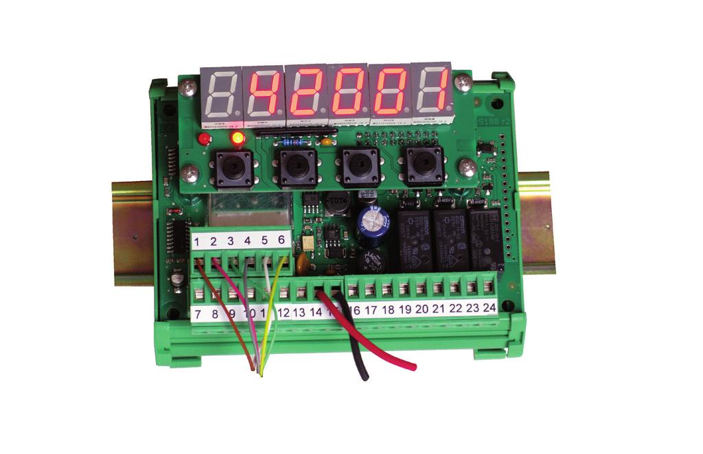
8 SUMMARY OF WIRINGS PIN 6 Pin pull-out terminal block 1 Load cell Excitation - 2 Load cell Excitation + 3 Load cell Sense + 4 Load cell Sense - 5 Load cell Signal - 6 Load cell Signal + NUM. 18 Pin pull-out terminal block 7 TX (RS232) 8 RX (RS232) 9 GND (RS232) 10 TX/RX + (RS485) 11 TX/RX - (RS485) 12 Logic input 13 Logic input 14 + ~ 15 - ~ Dry contact Power supply 12 to 24 Vdc/Vac +/- 15% 16 Analog output + (V or ma) 17 Analog output - 18 Common Relay Output 1 19 N.O. contact Relay Output 1 20 Common Relay Output 2 21 N.O. contact Relay Output 2 22 Common Relay Output 3 23 N.O. contact Relay Output 3 24 N.C. contact Relay Output 3 Connect the shield of the load cell cable to the excitation (pin #1). The serial and analog output cables shield must be grounded at one end only. Page 7


9 PAVONE SISTEMI S.R.L. Via Tiberio Bianchi 11/13/15, Concorezzo (MB), ITALY T F W en.pavonesistemi.it Industrial Electronic Weighing Systems since 1963
Cyfrowy przetwornik wzmacniający dedykowany dla czujników tensometrycznych
 Cyfrowy przetwornik wzmacniający dedykowany dla czujników tensometrycznych RQ INSTALLATION MANUAL Rev. 0.2 INDEX DEVICE PROPERTIES TECHNICAL PROPERTIES Pag. 2 TECHNICAL PROPERTIES (follow) Pag. 3 SYMBOLS
XT-9100 Technical Bulletin
 System 9100 Technical Manual 636.4 Technical Bulletins Section Technical Bulletin Issue Date 0896 XT-9100 Technical Bulletin XT-9100 Extension Module/XP-910x Expansion Modules Page 3 Introduction 3 SX
TESTER 1008 for checking simultaneously a weighing system with up to 4 load cells. Pavone Sistemi USER MANUAL. Pavone Sistemi
 Pavone Sistemi pesatura elettronica industriale USER MANUAL TESTER 1008 for checking simultaneously a weighing system with up to 4 load cells Calibrator and mv/v signal simulator Software version P28901
SX90 Process Controller
 Local regulations may restrict the use of this product to below the conditions quoted. In the interests of development and improvement of the product, we reserve the right to change the specification without
Strain Gauge Converter
 EN Z-SG General Description Module Z-SG is a strain gauge signal converter. Measurements taken using the 6-wires or 4-wires technique are available through Modbus-RTU serial protocol or the analog output.
IO-AO6X I/O Expansion Module 6 Isolated Analog Outputs
 IO-AO6X I/O Expansion Module 6 Isolated Analog Outputs The IO-AO6X is an I/O Expansion Module that can be used in conjunction with specific Unitronics OPLC controllers. The module offers 6 12-bit isolated
S SENECA. Installation Manual Z-TWS4. Z-PC Line. Web Multifunction Controller Straton / Linux
 S SENECA Z-PC Line EN Installation Manual Contents: - General specifications - Technical features - Modbus and CANopen connections - Installation rules - Electrical connections - LEDs signallings - Default
Rhino Buffer Module PSM24-BFM600S. Operating Instructions
 Rhino Buffer Module PSM24-BFM600S Operating Instructions RHINO BUFFER MODULE PSM24-BFM600S Description The PSM24-BFM600S Buffer Module will hold the output voltage of a 24 VDC power supply after brownouts
TRACKER 240 SERIES. Load Cell and Weighing Indicators. A Precision Measurement Instrument with Outstanding Features
 TRACKER 240 SERIES Load Cell and Weighing Indicators A Precision Measurement Instrument with Outstanding Features TRACKER 240 SERIES INDICATORS Ratiometric Measurement Tare and Auto Transducer Excitation
EX-RC1 Remote I/O Adapter
 EX-RC1 Remote I/O Adapter The EX-RC1 interfaces between Unitronics Vision OPLCs and remote I/O Expansion Modules distributed throughout your system. The adapter is connected to a PLC via CANbus. Each adapter
Specification Sheet For electronically commutated motors
 SC-VAV-N Specification Sheet For electronically commutated motors Used in constant pressure applications The SC-EFC is designed to control exhaust air in various building applications. The system includes
LCI Load Cell Junction Box with Fault Monitor
 LCI Load Cell Junction Box with Fault Monitor User Manual www.mantracourt.co.uk The LCI Load Cell Failure Alarm Manual Chapter 1 Introduction to the LCI...2 Chapter 2 Installing the LCI...3 Figure 2.1
USER MANUAL. WBV412U01 AC voltage transducer
 Designing, Manufacturing and Supplying WB Series Electric Isolated Sensor and Digital Electrical Transducer since 1989 USER MANUAL WBV412U01 AC voltage transducer www.wb-my.com wblch@wbdz.cn Technical
LCI User Manual mantracourt.com
 LCI User Manual mantracourt.com LCI Load Cell Junction Box with Fault Monitor Contents Chapter 1 Introduction to the LCI... 2 Chapter 2 Installing the LCI... 3 Chapter 3 Setting up the LCI... 4 Sequence
USER MANUAL MULTI COLOR TOUCH SCREEN PAPERLESS RECORDER MODEL : ARC2020
 USER MANUAL MULTI COLOR MODEL : ARC2020 ACCSYS ELECTRONICS 140/6B, GOLDEN INDUSTRIAL ESTATE, JAWAHARLAL NEHRU ROAD, GERUGAMBAKKAM, CHENNAI - 600122 Tel: 044 60505599 / 60505511 E-mail : sales@accsyselectronics.com
DIGITAL DISPLAY. for Industry Applications. Series WAY-SSI. Key-Features:
 DIGITAL DISPLAY for Industry Applications Series WAY-SSI Key-Features: Content: Technical Data.2 Technical Drawing...2 Electrical Connection...3 Description...4 Order Code & Accessories...6 - WAY-SSI-S:
Energy Management Modular DC Energy analyzer Type VMU-E and VMU-X
 Energy Management Modular DC Energy analyzer Type VMU-E and VMU-X Modular solution based on the combination of two units: VMU-E analysis unit and VMU-X universal power supply and RS485 communication unit.
Process displays For current and voltage
 Features Voltage input TRMS-AC/DC up to 600 V Current input AC/DC 1 A, 5 A and shunt (precision resistor) 60 or 100 mv With 2 or 4 limits Display range can be linearised Min, Max, Hold functions 4 20 ma
PRODIS. PD-ADC Digital Process Meter for analog Sensors. Digital Process Meters. Datasheet
 Digital Process Meters Digital Process Meter for analog Sensors Datasheet Copyright ASM GmbH Am Bleichbach 18-24 85452 Moosinning Germany The information presented in this data sheet does not form part
User Manual. MS657140X Industrial Fast Ethernet Switch 8x 10/100Base-TX
 User Manual MS657140X Industrial Fast Ethernet Switch 8x 10/100Base-TX CE MARKING This equipment complies with the requirements relating to electromagnetic compatibility, EN 55022 class A for ITE, the
USER MANUAL MULTI COLOR TOUCH SCREEN PAPERLESS RECORDER TPLR-96 Series
 USER MANUAL MULTI COLOR TOUCH SCREEN PAPERLESS RECORDER TPLR-96 Series TEMPSEN DEVICES Plot No : 2&3, Balaji Nagar, 4 th Street, Mettukuppam, Thoraipakkam, Chennai-600097 Tele fax : +91-44-24581758,Mobil
Analog Amplifier FAA-27. Technical Manual. Flintec GmbH Bemannsbruch Meckesheim GERMANY.
 Analog Amplifier FAA-27 Technical Manual Flintec GmbH Bemannsbruch 9 74909 Meckesheim GERMANY www.flintec.com Table of Contents 1. Safety Instructions... 2 2. Declaration Of Conformity... 3 3. Front View,
EX-RC1 Remote I/O Adapter
 EX-RC1 Remote I/O Adapter The EX-RC1 interfaces between Unitronics Vision OPLCs and remote I/O Expansion Modules distributed throughout your system. The adapter is connected to a PLC via CANbus. Each adapter
MODEL: R1M-A1. PC Recorders R1M Series. SPECIFICATIONS OF OPTION: Q COATING (For the detail, refer to M-System's web site.)
") PC Recorders R1M Series PC RECORDER (contact input, 32 points) Functions & Features Industrial recorder on PC 32-point dry contact inputs Easy system expansion via Modbus RTU Recorded data exportable to
PC Recorders R1M Series PC RECORDER (contact input, 32 points) Functions & Features Industrial recorder on PC 32-point dry contact inputs Easy system expansion via Modbus RTU Recorded data exportable to
SDM-6RO. Expansion Module 6 relay outputs. Manufactured for
 Version 1.0 5.02.2014 Manufactured for Thank you for choosing our product. This manual will help you with proper support and proper operation of the device. The information contained in this manual have
Measuring transducers MI4x0 series Programmable transducers for RTD sensors MI450
 Measuring transducers MI4x0 series Programmable transducers for RTD sensors MI450 o Measuring of resistance of RTD sensors (Pt100, Pt1000, Ni100, Cu10,...) o Accuracy class up to: 0.5 o Programmable input
INSTALLATION DKM-409 NETWORK ANALYSER WITH HARMONIC MEASUREMENT AND SCOPEMETER. Before installation:
 DKM-409 NETWORK ANALYSER WITH HARMONIC MEASUREMENT AND SCOPEMETER The DKM-409 is a precision instrument designed for displaying various AC parameters in 3-phase distribution panels. Thanks to its isolated
Lantech. IPES /100TX with 4 PoE Injectors 24~48VDC Industrial Switch. User Manual
 Lantech IPES-0008-4 8 10/100TX with 4 PoE Injectors 24~48VDC Industrial Switch User Manual V1.00 Jun 2010 FCC Warning This Equipment has been tested and found to comply with the limits for a Class-A digital
See instructions to download and install the latest version of LinkBoxEIB and the user's manual at
 Safety Instructions WARNING Follow carefully this safety and installation instructions. Improper work may lead to serious harmful for your health and also may damage seriously the IntesisBox and/or any
1/32-DIN TEMPERATURE CONTROLLER INSTALLATION, WIRING AND OPERATION MANUAL FORM 3882
 1/32-DIN TEMPERATURE CONTROLLER INSTALLATION, WIRING AND OPERATION MANUAL FORM 3882 This manual is intended for use in support of installation, commissioning and configuration of the 1/32-DIN Temperature
User Manual. MS657208X Industrial Gigabit Ethernet Switch 8x 10/100/1000Base-T
 User Manual MS657208X Industrial Gigabit Ethernet Switch 8x 10/100/1000Base-T CE MARKING This equipment complies with the requirements relating to electromagnetic compatibility, EN 55022 class A for ITE,
Installation Instructions
 TM Installation Instructions Manual 10 - Star Driver Modules PY-STR, PY-STR-L, PY-STR-H and PY-STR-2-H Read also: Installation Instructions, Manual 2 - Network Wiring Please read this manual completely
I/O SIGNAL CONDITIONER
 Technical Data Sheet No. TD9809M Rev. F Date of Issue: December 9, 2009 OPERATING MANUAL I/O SIGNAL CONDITIONER CAUTION: THIS PRODUCT DOES NOT PROVIDE GALVANIC ISOLATION. DO NOT ATTEMPT USE OF THIS PRODUCT
IO-LC1, IO-LC3 I/O Expansion Modules 1-3 Loadcell Inputs, 1 Digital In, 2 Out
 IO-LC1, IO-LC3 I/O Expansion Modules 1-3 Loadcell Inputs, 1 Digital In, 2 Out The IO-LC1 and IO-LC3 are I/O Expansion Modules that can be used in conjunction with specific Unitronics OPLC controllers.
USER INSTRUCTION MANUAL FOR LOADCELL TRANSMITTER MODEL TDC/I/0550 (SOFTWARE: VER2A) INDEX
 INDEX") USER INSTRUCTION MANUAL FOR LOADCELL TRANSMITTER MODEL TDC/I/0550 (SOFTWARE: VER2A) INDEX DOCUMENT NO: TDC 0550 MANUAL - 2 1.0) INTRODUCTION. PAGE 2 1.1) ABOUT THIS MANUAL. PAGE 2 1.2) INTRODUCTION. PAGE
USER INSTRUCTION MANUAL FOR LOADCELL TRANSMITTER MODEL TDC/I/0550 (SOFTWARE: VER2A) INDEX DOCUMENT NO: TDC 0550 MANUAL - 2 1.0) INTRODUCTION. PAGE 2 1.1) ABOUT THIS MANUAL. PAGE 2 1.2) INTRODUCTION. PAGE
See instructions to download and install the latest version of LinkBoxEIB and the user's manual at
 Safety Instructions WARNING Follow carefully this safety and installation instructions. Improper work may lead to serious harmful for your health and also may damage seriously the IntesisBox and/or any
Energy Management Energy Transducer Type ET112
 Energy Management Energy Transducer Type Single phase energy transducer Class 1 (kwh according to EN62053-21 Class B (kwh according to EN50470-3 Accuracy ±0.5% RDG (current/voltage Direct current measurement
2 Table of Contents 1. TABLE OF CONTENTS. 1. Table of Contents Introduction Wiring Diagram Terminals Review...
 TPR-6 Temperature Protection Relay Instruction Manual Ver. June 1 st 2010 2 Table of Contents 1. TABLE OF CONTENTS 1. Table of Contents... 2 2. Introduction... 3 3. Wiring Diagram... 5 4. Terminals Review...
EX-RC1 Remote I/O Adapter
 EX-RC1 Remote I/O Adapter The EX-RC1 interfaces between Unitronics Vision OPLCs and remote I/O Expansion Modules distributed throughout your system. The adapter is connected to a PLC via CANbus. Each adapter
USER MANUAL. WBI412F41 AC current transducer
 Designing, Manufacturing and Supplying WB Series Electric Isolated Sensor and Digital Electrical Transducer since 989 USER MANUAL WBI2F AC current transducer www.wb-my.com wblch@wbdz.cn Technical Service:
USER MANUAL. WBI414F21 AC current transducer
 1 Designing, Manufacturing and Supplying WB Series Electric Isolated Sensor and Digital Electrical Transducer since 1989 USER MANUAL WBI1F21 AC current transducer www.wb-my.com wblch@wbdz.cn Technical
icex-cmtm General specs and Installation guide
 icex-cmtm General specs and Installation guide 1. General view 2. Specifications 2.1. Common specs: Ethernet 1 x 10/100Base/T, RJ45 connector with traffic and link LED Serial Interface 1 x RS232/485 USB
User s manual. Programmable panel meter IPD
 User s manual Programmable panel meter IPD Assembly Wall assembly: +0,5 +0,2 Window of 46 x 91 mm (2.5" x 3.5" ) Made with ABS (UL94-HB) -0-0 General cares in the installation The equipments must not be
RS485 MODBUS Module 6RO
 Version 2.0 12/02/2013 Manufactured for Thank you for choosing our product. This manual will help you with proper support and proper operation of the device. The information contained in this manual have
RS 485 Mini Modbus 1AO
 RS 485 Mini Modbus 1AO Version 1.0 14/08/2014 Manufactured for Thank you for choosing our product. This manual will help you with proper support and proper operation of the device. The information contained
INTEGRATED SYSTEMS AND CONTROL, INC. User s Hardware Manual. PCMNET V 7. xx
 INTEGRATED SYSTEMS AND CONTROL, INC. User s Hardware Manual PCMNET V 7. xx INTEGRATED SYSTEMS AND CONTROLS, INC. PCMNET Users Manual Revised 2/4/2005 2003-2005 Integrated Systems and Control. Inc. PO Box
DESIGO RX Individual room controllers. for fan-coil systems, chilled ceilings and radiators, with LONMARK-compatible bus communications
 3 834 DESIO RX Individual room controllers for fan-coil systems, chilled ceilings and radiators, with MARK-compatible bus communications RXC20.1 RXC21.1 The RXC20.1 and RXC21.1 controllers are used for
Motor Control and Protection Unit M10x AO Module User Guide
 Motor Control and Protection Unit M10x AO Module User Guide The information in this document is subject to change without notice and should not be construed as a commitment by ABB. ABB assumes no responsibility
GS400. Electronic Auto-Ranging DIN Panel Mounted Positioner
 GS400 Electronic Auto-Ranging DIN Panel Mounted Positioner Features * AC (115/230V) and DC (24V) versions available. * Accepts either current or voltage command signal and either current, voltage, or three
RTT2 ROOM TEMPERATURE SWITCH. Mounting and operating instructions
 Mounting and operating instructions Table of contents SAFETY AND PRECAUTIONS PRODUCT DESCRIPTION ARTICLE CODES INTENDED AREA OF USE TECHNICAL DATA STANDARDS OPERATIONAL DIAGRAMS WIRING AND CONNECTIONS
RS485 MODBUS Module 8I8O
 Expansion Module 8 digital inputs, 8 digital outputs Version 2.2 12/01/2014 Manufactured for Thank you for choosing our product. This manual will help you with proper support and proper operation of the
Output Signal Active Note DC V. Electrical Data Power Supply DC V, ±10%, 1.4 W
 Differential Pressure Sensor (Air) Differential pressure transmitter with 8 selectable ranges 0 to 5/10 V, 4 to 20 ma outputs and Modbus functionality. NEMA 4X / IP65 rated enclosure. For monitoring the
RXTH DUAL ROOM SENSOR / SWITCH
 DUAL ROOM SENSOR / SWITCH FOR TEMPERATURE AND RELATIVE HUMIDITY Mounting and operating instructions Table of contents SAFETY AND PRECAUTIONS 3 PRODUCT DESCRIPTION 4 ARTICLE CODES 4 INTENDED AREA OF USE
R1M-GH THERMOCOUPLE & DC INPUT MODULE MODEL. Remote I/O R1M Series. (16 points)
") Remote I/O R1M Series THERMOCOUPLE & DC INPUT MODULE (16 points) MODEL MODEL & SUFFIX CODE SELECTION R1MGH2T MODEL Modbus protocol I/O TYPE GH2 : Thermocouple or DC input, 16 points FIELD TERMINAL TYPE
Remote I/O R1M Series THERMOCOUPLE & DC INPUT MODULE (16 points) MODEL MODEL & SUFFIX CODE SELECTION R1MGH2T MODEL Modbus protocol I/O TYPE GH2 : Thermocouple or DC input, 16 points FIELD TERMINAL TYPE
NTP-5521/5531/5561 SWITCHING MODE POWER SUPPLY
 NTP-5521/5531/5561 SWITCHING MODE POWER SUPPLY USER MANUAL Keep this manual in a safe place for quick reference at all times. This manual contains important safety and operation instructions for correct
ACT-1B Series Panel Tachometer
 MONARCH INSTRUMENT Instruction Manual ACT-1B Series Panel Tachometer Printed in the U.S.A. Copyright 2009 Monarch Instrument, all rights reserved 1071-4843-111R 0909 15 Columbia Drive Amherst, NH 03031
MCX08M2 Programmable controller
 Data sheet MCX08M2 Programmable controller MCX08M2 is an electronic controller that holds all the typical functionalities of MCX controllers in the compact size of 8 DIN modules: programmability connection
I-7520: RS-232 to RS-485. Input: RS-232 protocol Output:RS-485/RS-422 Speed: Self Tuner 'inside, auto switching baud rate, 300~ BPS
 I-7520 RS-232 to RS-485 Converter I-7510 RS-485 Repeater RS-232 RS-485 I-7000 SERIES Common Specifications Isolation voltage: 3000VDC Speed: 1200, 2400, 4800, 9600, 19200, 38400, 57600, 115000 Dual watchdog
DXTH DUCT SENSOR / SWITCH FOR TEMPERATURE AND HUMIDITY. Mounting and operating instructions
 DUAL DUCT SENSOR / SWITCH FOR TEMPERATURE AND HUMIDITY Mounting and operating instructions Table of contents SAFETY AND PRECAUTIONS 3 PRODUCT DESCRIPTION 4 ARTICLE CODES 4 INTENDED AREA OF USE 4 TECHNICAL
HygroClip DI Digital Interface for HygroClip Probes v 1.0 Instruction Manual
 HygroClip DI Digital Interface for HygroClip Probes v 1.0 Instruction Manual page 2 of 15 Contents: Overview... 2 Models... 3 Power... 4 Probes... 4 Connector identification... 5 Pin-out diagrams... 6
RXTP ROOM TEMPERATURE
 ROOM TEMPERATURE CONTROLLER WITH PI CONTROL Mounting and operating instructions Table of contents SAFETY AND PRECAUTIONS 3 PRODUCT DESCRIPTION 4 ARTICLE CODES 4 INTENDED AREA OF USE 4 TECHNICAL DATA 4
ICF-1150 Series Quick Installation Guide
 ICF-1150 Series Quick Installation Guide Second Edition, March 2012 2012 Moxa Inc. All rights reserved. P/N: 1802011500011 Overview Introduction The ICF-1150 series fiber converters are equipped with a
ATS-16 HV USER MANUAL. Automatic Transfer Switch 16A / 230Vac V090318
 ATS-16 HV Automatic Transfer Switch 16A / 230Vac USER MANUAL V090318 SAFETY Intended use The ATS-16 HV device serves as a power source selector to provide improved power supply for connected loads. ATS-16
Rhino Redundancy Module PSM24-REM360S. Operating Instructions
 Rhino Redundancy Module PSM4-REM360S Operating Instructions RHINO REDUNDANCY MODULE PSM4-REM360S Description With this module and two power supplies of the PSM series (78, 90, 56, 80 and 360 watt models),
See instructions to download and install the latest version of LinkBoxMB and the user's manual at
 Safety Instructions WARNING Follow carefully this safety and installation instructions. Improper work may lead to serious harmful for your health and also may damage seriously the IntesisBox and/or any
INDICATOR FOR PROCESS CONTROL. Love Controls. LCI108J-0x INSTRUCTION MANUAL. EDITION: January Valid for models with software version P-1
 Love Controls INDICATOR FOR PROCESS CONTROL LCI108-0x LCI108J-0x INSTRUCTION MANUAL EDITION: January 2001 Valid for models with software version P-1 INTRODUCTION TO THE LOVE CONTROLS LCI108 SERIES This
Electronic Temperature Controller. Instruction Manual Version
 Electronic Temperature Controller 701 Instruction Manual Version 1.00.01 Dear Customer, we have made up this operating manual in such a way that all necessary information about the product can be found
MP-2000 Dual Channel LVDT/RVDT Readout/Controller
 Large backlit dual channel display Menu driven setup and calibration 100 to 240 VAC line powered MIN, MAX, TIR, A+B and A-B functions 2.5, 3.3, 5 and 10kHz selectable excitation Analog and RS232 outputs
CSI 6300 SIS Overview
 Overview The Digital Overspeed Protection System is TÜV - certified according to IEC 61508:2010 and provides speed measurement and detection of rotational direction for rotating machines such as turbines,
Multifunction Transducer MT440
 Multifunction Transducer MT440 Voltage and current auto range measurements up to 600V, 12.5A Universal wide auxiliary power supply range 24 300 Vdc, 40 276 Vac Power accuracy class 0.5 (EN 60 688), Up
PGR-3200 MANUAL INSULATION MONITOR
 Tel: +1-800-832-3873 E-mail: techline@littelfuse.com www.littelfuse.com PGR-3200 MANUAL INSULATION MONITOR REVISION 3-E-040918 Copyright 2018 by Littelfuse, Inc. All rights reserved. Document Number: PM-1025-EN
IES User Manual. 8 FE + 1 MM SC Unmanaged Switch -40 to 75, DIN-rail. v
 IES-0920 8 FE + 1 MM SC Unmanaged Switch -40 to 75, DIN-rail User Manual v1.00-1206 Preface This manual describes how to install and use the Industrial Ethernet Switch. This switch integrates full wire
OPERATING INSTRUCTIONS 7 SERIES STATIC GENERATORS
 OPERATING INSTRUCTIONS 7 SERIES STATIC GENERATORS GB Contents Page 1 Introduction 4 2 Safety 5 3 Use 6 4 Checking on Delivered Equipment 6 5 General Specification and Dimensions 7 6 Positioning 10 7 Operating
GUIDE PROGRAMMABLE PANEL METER M905
 USER S GUIDE PROGRAMMABLE PANEL METER M905 Please read instructions carefully. 30727265 03/2018 Force Torque Pressure Acceleration - Standard Sensors and Custom Specials! MEAS France SAS, a TE Connectivity
UniPak UP448 Bridge Input Isolating Signal Conditioner
 6-wire Bridge Connection Excitation for to 350 Ω Load Cells 500 Volt (3-way) Isolation Excellent Accuracy (0.0%) DIP Switch Configuration Digital Input Tare Calibration RS85 Modbus RTU Superior Flexible
ioselect Z-NET Z-SG Bridge Input Isolating I/O Module
 -wire Bridge Connection Excitation for to 30 Ω Load Cells 00 Volt (3-way) Isolation Excellent Accuracy (0.0%) DIP Switch Configuration Digital Input Tare Calibration RS8 Modbus RTU Superior Flexible Power:
RТTH DUAL ROOM SWITCH
 DUAL ROOM SWITCH FOR TEMPERATURE AND RELATIVE HUMIDITY Mounting and operating instructions Table of contents SAFETY AND PRECAUTIONS PRODUCT DESCRIPTION ARTICLE CODES INTENDED AREA OF USE TECHNICAL DATA
MPI-DN, MPI-D MULTICHANNEL ELECTRONIC RECORDER for HART or RS-485/ MODBUS RTU SENSORS
 MPI-DN, MPI-D MULTICHANNEL ELECTRONIC RECORDER for HART or RS-485/ MODBUS RTU SENSORS 18 channels for HART / Modbus RTU sensors 2 digital channels 16 math channels 4 relay outputs for alarm or control
RS485 MODBUS Module 8I8RO
 Expansion Module 8 digital inputs, 8 relay outputs Version 1.0 3.12.2014 Manufactured for Thank you for choosing our product. This manual will help you with proper support and proper operation of the device.
SDM-8AO. Expansion Module 8 analog outputs. Manufactured for
 Version 1.0 16.05.2014 Manufactured for Thank you for choosing our product. This manual will help you with proper support and proper operation of the device. The information contained in this manual have
EWCH 485 Electronic Pulse Counter
 Electronic Pulse Counter Technical Data Sheet INSTRUMENT DESCRIPTION GENERAL DESCRIPTION is a programmable microprocessor based counter with 1or 2 outputs. The instrument offers the possibility to program:
Modulating controlled actuators AME 10, AME 20, AME 30 AME 13, AME 23, AME 33 - with DIN EN certified safety function (spring down)
") Data sheet Modulating controlled actuators AME 10, AME 20, AME 30 AME 13, AME 23, AME 33 - with DIN EN 14597 certified safety function (spring down) Description AME 10 AME 13 AME 20, AME 30 AME 23, AME
Data sheet Modulating controlled actuators AME 10, AME 20, AME 30 AME 13, AME 23, AME 33 - with DIN EN 14597 certified safety function (spring down) Description AME 10 AME 13 AME 20, AME 30 AME 23, AME
MODEL: M5DY SEN TRONIC AG CURRENT LOOP SUPPLY. [2] POWER INPUT AC Power M: V AC (Operational voltage range V, Hz)
![MODEL: M5DY SEN TRONIC AG CURRENT LOOP SUPPLY. [2] POWER INPUT AC Power M: V AC (Operational voltage range V, Hz)](/thumbs/90/103899684.jpg "MODEL: M5DY SEN TRONIC AG CURRENT LOOP SUPPLY. [2] POWER INPUT AC Power M: V AC (Operational voltage range V, Hz)") Super-mini Terminal Block Signal Conditioners M5-UNIT CURRENT LOOP SUPPLY Functions & Features Powering a 0 ma DC current loop Applicable to smart transmitters Isolation between the input and output Fast
Super-mini Terminal Block Signal Conditioners M5-UNIT CURRENT LOOP SUPPLY Functions & Features Powering a 0 ma DC current loop Applicable to smart transmitters Isolation between the input and output Fast
AB Axis Industries. Use
 AB Axis Industries PULSE ADAPTER ENCO PULSE The ENCO PULSE pulse adapter acquires and handles the pulses from consumption meters with pulse output and transmits the data to a network of AMR system. Use
PM174 PM174 IEEE1159 ADVANCED POWER QUALITY ANALYZER. Features
 PM174 IEEE1159 ADVANCED POWER QUALITY ANALYZER The PM174 is a compact, multi-function, three-phase AC powermeter and power quality analyzer specially designed to meet the requirements of users ranging
Multi-instrument Communication, MIC-2 MKII DIN Quick Start Guide
 Multi-instrument Communication, MIC-2 MKII DIN Quick Start Guide Warnings and legal information Installation and terminals Communication I/O options Alarming Utility software More information Specifications
Installation & Operation Guide
 Installation & Operation Guide (Shown with optional Override Board Cover) KMD-5831 Programmable Loop Controller PLC-28 Direct Digital Controller 902-019-04B 1 Introduction This section provides a brief
IO-PT4. Component identification. User safety and equipment protection guidelines. Unitronics Industrial Automation Systems 1
 IO-PT4 I/O Expansion Module 4 PT100 Inputs (-50 to 460 C) The IO-PT4 is an I/O expansion module that can be used in conjunction with specific Unitronics OPLC controllers. The module offers 4 PT100 inputs
DIGITAL PANEL THERMOMETER
 Love Controls DIGITAL PANEL THERMOMETER LCI108-2x LCI108J-2x INSTRUCTIONS MANUAL EDITION: February 2001 INTRODUCTION TO THE LOVE CONTROLS LCI108 SERIES This manual does not constitute a formal agreement.
Signal Doublers. VariTrans A 20300
 ProLine Interface Technology Signal Doublers Signal doublers with two switchable calibrated outputs in a 6 mm housing, also for applications with high output loads. The Task Isolation and transmission
RS232 Control Box. Table of contents
 Control Box Table of contents Page Introduction... Installation...5 Mounting the box System cable External power supply Location of switches and connectors Internal switch settings...8 Possible configurations...9
Operating Instructions Differential Pressure Transducer PS27
 Operating Instructions Differential Pressure Transducer PS27 halstrup-walcher GmbH Stegener Straße 10 79199 Kirchzarten/Germany Phone: +49 (0) 76 61/39 63 0 Fax: +49 (0) 76 61/39 63 99 E-mail: info@halstrup-walcher.com
Operating Instructions. Power Supply & Latching Relay For Switches Model: RL manual_rl-6000_1016
 Operating Instructions Power Supply & Latching Relay For Switches Model: RL-6000 manual_rl-6000_1016 1. Contents 1. Contents...2 2. Note...3 3. Instrument Inspection...3 4. Regulation Use...3 5. Operating
EY-EM : Remote I/O module, ecolink
 EY-EM 510...512: Remote I/O module, ecolink510...512 How energy efficiency is improved Optimum adjustment to applications by means of module technology. Reduction in wiring Features Part of the SAUTER
SoundwebTM. Installation Guide
 105 SoundwebTM Soundweb TM 9000 Installation Guide Soundweb TM Regulatory Information An example of this equipment has been tested and found to comply with the following European and international Standards
Power Meter PowerMonitor 500
 ROCKWELL AUTOMATION PROCUREMENT SPECIFICATION PROCUREMENT SPECIFICATION PowerMonitor 500 NOTICE: The specification guidelines in this document are intended to aid in the specification of products. Specific
IP67 VERSION BOX (on request) 8+3 PG9 cable glands-plugs. 8+3 PVC fittings for sheath
 8+3 PG9 cable glands-plugs. 8+3 PVC fittings for sheath") Digital/analog weight transmitter suitable for back panel mounting on Omega/DIN rail or junction box for field mounting (on request box versions). Weighing system with 8 independent reading channels with
Digital/analog weight transmitter suitable for back panel mounting on Omega/DIN rail or junction box for field mounting (on request box versions). Weighing system with 8 independent reading channels with
Component identification
 IO-ATC8 I/O Expansion Module 8 Analog/Thermocouple Inputs The IO-ATC8 is an I/O Expansion Module that can be used in conjunction with specific Unitronics OPLC controllers. The module offers 8 inputs that
VCL-TP, Teleprotection Equipment
 VCL-TP, Teleprotection Equipment Data Sheet Copyright: Valiant Communications Limited. - 2013 1 Product Overview VCL-TP, Teleprotection Equipment is an extremely reliable and flexible product that offers
ICF-1150 Series Quick Installation Guide
 ICF-1150 Series Quick Installation Guide Fifth Edition, July 2015 2015 Moxa Inc. All rights reserved. P/N: 1802011500014 1802011500014 Overview Introduction ICF-1150 series fiber converters have a multi-interface