Installation and Programming Guide
|
|
|
- Tamsyn Reed
- 6 years ago
- Views:
Transcription

1 PRT-EM Series EM 125 khz Access Terminals Firmware v1.29 and v2.29 Rev. K This document refers to the following products: - PRT12EM - PRT12EM-BK - PRT32EM - PRT42EM - PRT42EM-BK - PRT62EM - PRT64EM - PRT64EM-VP - PRT66EM Installation and Programming Guide
2 1. GLOSSARY OF TERMS IMPORTANT NOTES Compatibility Rules About This Manual GENERAL DESCRIPTION Features General Terminal Mode (Online Mode) Standalone Mode (Offline Mode) Proximity Cards T5555 and T5557 Cards Function Keys OPERATING MODES Terminal Mode Wiegand Formats Magstripe Formats RACS Format RS232, EPSO Protocol (9600, N, 8, 1) RS232, Cards and Keys (9600, N, 8, 1) RS232, Cards and PIN-s (9600, N, 8, 1 ) Standalone Mode Full Standalone Mode Simple Standalone Mode STANDALONE MODE Users Managing the Users User Identification Door Unlocking Facility Code Arming Modes Arming/Disarming Methods Door Bell Function Function Keys Page 2 from 59
3 5.7. Door Alarm Tamper Alarm Intruder Alarm Duress Alarm General Alarm Events Recording Real Time Clock Timers Optical and Acoustic Signals Operation with XM-2 I/O Extension Module Operation with Second PRT Series Reader PROGRAMMING Programming the PRT-EM Readers without Keypad Programming Through Multiple Readings of the Programming Card Programming From The External Reader Memory Reset OPERATING MODES INSTALLER PROGRAMMING Input/Output Functions USER PROGRAMMING MODE User Programming Commands PROGRAMMING FROM PC Programming via RS232 COM port Programming via RUD-1 interface Firmware Upgrade Firmware upgrade via RS232 COM port Firmware upgrade via RUD-1 interface INSTALLATION GUIDELINES Page 3 from 59
4 1. G LOSSARY OF T ERMS Door Release or Door Lock Electric device used to lock/unlock a door. Typically it can be a door strike, solenoid lock or magnetic lock. Identifier The physical item or method which is used for identification of users. It can be a proximity card, a PIN code, a finger template etc. In some cases identifier may consist of two or more items required for a single identification procedure. For example when option Card and PIN is active then Identifier=Card+PIN. Identification Mode The method used for identification of users, it can be Card or PIN, Card and PIN, Card only, PIN only etc. Memory Reset The procedure which clears contents of device s memory and restores default (factory) settings. PRT Series Readers The PRT reader s family developed and manufactured by Roger. Restart The situation when device goes through the initialization procedure, the same as when it is powered up. Roger Access Control System (RACS) The access control system which consists of PR series access controllers developed and manufactured by Roger. Access Control Unit (ACU) The logic device which provides access control, usually it is an access controller. XM-2 I/O Extension Module The remote I/O extension module for RACS system. The XM-2 provides two NO/NC inputs and two relay outputs. Full Standalone Mode The operation mode in which reader autonomously controls a door passage. When operating in Full Standalone Mode the PRT-EM reader requires the remote XM-2 extension module, also in this mode it can operate with another (second) PRT series reader thus providing two-way passage control. Simple Standalone Mode The operation mode in which reader independently controls a door passage. When in Simple Standalone Mode the PRT-EM reader uses its internal I/O lines as general purpose I/Os but is not capable to operate with XM-2 I/O module and/or second PRT series reader. RACS Interface The electrical interface and addressable protocol developed by Roger. This interface is implemented in access readers and controllers manufactured by Roger. The RACS interface uses two communication lines (CLK and DTA) and proprietary communication protocol capable to address up to 16 devices. EPSO Protocol The addressable, half duplex, serial communication protocol developed by Roger. This protocol allows a host device (PC or controller) for direct control of the reader s hardware through the set of remote commands. Page 4 from 59
5 RARC Program This program allows for programming and maintenance of the PRT series reader which are equipped with serial communication interface. RogerISP Program This program allows for firmware upgrade in access controllers and readers manufactured by Roger. Page 5 from 59
6 2. I MPORTANT N OTES Note: The PRT-EM term refers to any type of access terminal from PRTxxEM series readers. It is clearly indicated when given information refers solely to specific device and is not valid for entire series. The PRT-EM reader can be configured for several operating modes however the factory shipped unit is pre-configured for RACS address ID=0. The PRT-EM reader can be programmed in following ways: Manually from the keypad located on primary reader (when available) Manually from the keypad located on secondary reader (when available) Manually by multiple readings of the so called Programming Card Remotely from PC computer with RARC program If the reader is dedicated for operation in standalone mode (offline operation) and has to be programmed manually, it is necessary to program two special users into the reader: MASTER and INSTALLER, each of them can have card and/or PIN. Any proximity card or tag can be programmed as MASTER or INSTALLER card. The same card can be programmed as MASTER or INSTALLER card to multiple readers. Whenever required (e.g. when stolen or lost) the new MASTER and INSTALLER cards can be programmed into given unit. No proximity cards are shipped with factory new unit - if necessary, installer must arrange and enroll them to the reader by himself. Note: If after power up the LED SYSTEM is lit it means that contents of reader s memory is corrupted. In this case reader must be initialized and programmed anew COMPATIBILITY RULES Always check the firmware and hardware version for which manual is dedicated. Using wrong version of manual may cause that device will not behave as described in document. Also, when you upgrade firmware in the reader assure that the new firmware is dedicated for given type of reader (it must be clearly stated that given firmware is dedicated for given type of product you have). Once the firmware is uploaded assure adequate manual for the upgraded device ABOUT THIS MANUAL This manual is dedicated for all versions of PRT-EM readers: with keypad and without keypad. No matter if the PRT-EM readers have built-in keypad or not they represents the same logical functionality. The only difference between various types of PRT-EM series readers is limited to theirs mechanical construction, environment in which they can be installed and keypad which exist in limited number of PRT-EM readers. As the result of these the same configuration settings can be used to program various members of PRT-EM readers; also using RARC program configuration settings can be transferred (copied) between different members of PRT-EM family. Theoretically, it is possible to program and use PIN codes and other functions related with keypad on PRT-EM readers which are not physically equipped with keypad however this has practical sense only when PRT-EM reader without keypad operates in Full Standalone Mode with another (second) PRT-EM reader which has built-in keypad. In such scenario users can utilize keypad functions (including PIN codes) on this second (slave) reader. When PIN codes are programmed into reader without keypad it is obvious that they cannot be used on this individual reader however still they will exist in configuration settings of this particular unit and can be transferred from the reader to PC and then to another PRT-EM unit. Page 6 from 59
7 3. G ENERAL D ESCRIPTION The PRT-EM readers have been designed for use in access control installations to enable user identification via EM 125 KHz (and compatible) proximity cards and/or PIN-s. Readers can be configured for standalone operation (Offline Mode) or as an ordinary slave readers (Online Mode) connected to the external access control unit (ACU) supporting compatible data interface formats, this kind of operation is called Terminal Mode. When configured for standalone operation PRT-EM reader independently (i.e. autonomously) controls the supervised door access point. For this mode reader offers two variants of installation: first of them uses the reader s built-in I/O signal lines as programmable inputs and outputs, the second one uses them for communication with external XM-2 I/O module and second (optional) PRT series reader. An access control installation containing two PRT readers (one at the entry and other at the exit side of the supervised door) enables two-way door control. Also, the system setup utilizing the XM-2 module provides higher level of security for the entire door access control system by separating its logical element (reader) from the relay which physically controls a door lock. The PRT-EM reader configured for Terminal Mode works as a slave unit serving a sole purpose of reading cards/pin-s then providing subsequent transmission of such collected data to host ACU for further processing. Reader offers several data transmission formats including popular Wiegand and Magstripe data protocols. The PRT-EM reader can be also used as T5555 (Q5) and T5557 type card writer however the standard version of RARC program which is distributed for free doesn t support card programming function. In order to use the reader as a card writer apply for special license available for the RARC program FEATURES General EM 125 KHz proximity cards (EM4100/4102 compatible) T5555 (Q5) and T5557 card programmer (*) Up to 15 cm reading range Can operate with second PRT series reader as a slave unit Tamper switch Configurable as standalone access unit or slave reader Various operating temperatures (depend on particular reader) Outdoor and indoor installations (depend on particular reader) Programming and firmware upgrade through serial port RARC configuration program (for Windows) (*) - when operating with licensed version of the RARC program (contact Roger for more details) the PRT-EM reader can be used as T5555 (Q5) and T5557 card programmer Terminal Mode (Online Mode) 26/32/32 reversed/34/42/66 bit Wiegand data formats Magstripe data format (ABA Track II emulation) RACS data output format (Roger format) RS232, EPSO protocol RS232, direct output of cards and keys RS232, direct output of cards and PIN-s Various options for transmission of PIN-s and keys LED control input BUZZER control input Standalone Mode (Offline Mode) System settings stored in nonvolatile memory 120 indexed users with card and/or PIN-s Page 7 from 59
8 User indexing (ID indexed user records) Card or PIN or Card and PIN identification Real time clock (100 year) Automatic winter/summer time change 1000 event log Built-in 1.5A relay output Support for door contact and exit button Door Alarm and Door Bell outputs Integration with the alarm system trough I/O-s Two way door control (requires second PRT reader) Operation with XM-2 I/O extension module (Full Standalone Mode) 3.2. PROXIMITY CARDS The PRT-EM was designed for EM 125 KHz proximity cards compatible with EM 4100/4102 transponders. When in online mode reader returns card number without check sum bits. Card number is transmitted starting from the LSB to MSB and if required (it depends on the data output format selected for the given reader) can be supplemented with leading zeros or reduced on the MSB positions T5555 and T5557 Cards The T5555 (Q5) and T5557 cards are special type of EM cards which can be programmed. Using any PRT-EM reader together with licensed version of RARC program it is possible to read and write card s Chip Serial Number FUNCTION KEYS Some of the PRT-EM series readers are equipped with two (e.g. PRT12EM) or one (PRT42EM and PRT42EM-BK) function keys: [F1]- marked with door bell icon and [F2] marked with the light bulb icon. The function of each function keys depends on the reader s operation mode. When in RACS Mode, pressing function key will cause transmission of the relevant code to the host controller which can further take adequate action (e.g. trigger door bell, light etc.). The host s reaction for function key always depends on its configuration. When in Wiegand or Magstripe modes, pressing the F1/F2 causes following codes send over the output lines: For Wiegand: For Magstripe: F1=C hex F2=D hex F1=FF FF FF FF BC hex ( dec) F2=FF FF FF FF BD hex ( dec) When PRT-EM operates in standalone mode (either Full Standalone Mode or Simple Standalone Mode) by default the F1/F2 keys work as door bell buttons however they can be eventually configured to control AUX1/AUX2 outputs. Also, in Full Standalone Mode function keys on secondary reader (if available) have the same functions as assigned for function keys on main reader even when the main reader has no keys at all. Page 8 from 59
9 4. O PERATING M ODES There are two main modes of operation available for the PRT-EM reader: Terminal Mode (Online Mode) Standalone Mode (Offline Mode) 4.1. TERMINAL MODE In this mode reader operates as a slave unit connected to the external access controller. In Terminal Mode reader transmits collected data (card or PIN) to the host for further processing. The PRT-EM offers following data transmission formats: Wiegand 26bit Wiegand 32bit, normal mode (from MSB to LSB) Wiegand 32bit, reverse order (from LSB to MSB) Wiegand 34bit Wiegand 42bit Wiegand 66bit Magstripe (ABA Track II emulation, also called Clock & Data) RACS (for communication with PR series of controllers from Roger) RS232, EPSO protocol (transactional protocol, reader responses commands received from the host) RS232, cards and individual keys RS232, cards and PIN-s Wiegand Formats When employing Wiegand transmission format, data is send to the host using sequences of short pulses transmitted over CLK and DTA lines. Depending on the selected version of the transmission format, the reader can send 26, 32, 34, 42 or 66 bits to the host. In Wiegand format, a dual color LED STATUS lights steady in red, LED OPEN is controlled by IN1 while buzzer is controlled by IN2. Both inputs (IN1 and IN2) are triggered by shorting them to supply minus. In addition, whenever card is read or PIN is entered reader activates momentary LED SYSTEM and buzzer. Note: For card codes which require more bits than the number of bits available in the selected data transmission format, reader omits the most significant bits (MSB-s) of the card code. As a result transmission from a reader is not equal to the full card code. Page 9 from 59
 are triggered by supply minus.")

10 Magstripe Formats When employing Magstripe transmission format, data is transferred to the host using electric signal waves transmitted over the CLK and DTA lines. In Magstripe format a dual color LED STATUS lights steady in red, LED OPEN is controlled by IN1 while buzzer is controlled by IN2. Both inputs (IN1 and IN2) are triggered by supply minus. In addition, whenever card is read or PIN is entered reader activates momentary LED SYSTEM and buzzer. Card code is always transmitted as a whole number (no digits are lost) RACS Format When employing RACS format, the PRT-EM unit communicates with the host via CLK/DTA lines. Unlike in the Wiegand and Magstripe formats, the PRT-EM unit using RACS format requires an individual address (ID=0 3) to be set during configuration of the reader. With RACS format, communications between the PRT-EM reader and the host is bilateral, this allows controller to monitor communication. The reader s LED-s and the buzzer are controlled by the host unit. Note: When all LED-s are flashing it indicates that reader lost communication with the host unit. When in RACS mode triggering of the IN1 disables reading of the card and keypad. This input can be used for temporary disabling of the reader. The IN2 is not used in RACS mode RS232, EPSO Protocol (9600, N, 8, 1) When programmed to this protocol reader operates in transaction mode, i.e. responds only to external commands received through the RS232 port. The software developer or system integrator must incorporate EPSO protocol into the host device (usually PC or microcontroller) to communicate with the reader. In RS232 EPSO reader answers only those data packets which come from the host unit and are addressed with reader s ID number (address). The EPSO protocol is the set of communication functions used to control the reader s hardware (inputs, outputs, LED-s, buzzer, keypad and reading of cards). The PRT-EM configured for EPSO mode acts as pure terminal, it means that it strictly follows commands received from the host unit. The full description of EPSO protocol can be found on RS232, Cards and Keys (9600, N, 8, 1) Once the card is read or key is pressed reader outputs card/pin data on TXD transmission line. Reader outputs card code as 10 hex number while each pressed key is transmitted separately as 2 hex coded ASCI characters. Output Format for Cards STX DATA CR LF ETX 02 hex 10 hex digits coded ASCII 0D hex 0A hex 03 hex Page 10 from 59
11 Output Format for Keys STX DATA CR LF ETX 02 hex 2 hex digits coded ASCII 0D hex 0A hex 03 hex Key Codes Key * # F1 F2 Code F0 E1 D2 C3 B4 A A 4B 3C 2D RS232, Cards and PIN-s (9600, N, 8, 1 ) Once the card is read or PIN code is entered reader outputs card/pin data on TXD transmission line. Reader outputs card code as 10 hex digit number, PIN code is transmitted as whole number max. 16-digit long. Each pressed key is buffered and transmitted as a whole PIN when [#] key is pressed. The [#] key is treated as the end of the PIN. Output format for cards STX DATA CR LF ETX 02 hex 10 hex digits coded ASCII 0D hex 0A hex 03 hex Output format for PIN-s STX DATA # CR LF ETX 02 hex 16 hex digits coded ASCII 23 hex 0D hex 0A hex 03 hex The [*], [F1] and [F2] keys are transmitted in this format in the same way as PIN-s: [*]: STX / 'A' / '#' / CR / LF / ETX [F1]: [F2]: STX / 'C' / '#' / CR / LF / ETX STX / 'D' / '#' / CR / LF / ETX 4.2. STANDALONE MODE The PRT-EM reader offers two sub-modes for standalone operation: Full Standalone Mode Simple Standalone Mode In both modes reader is capable of providing independent (i.e. autonomic) control of a single door passage. Page 11 from 59

12 Full Standalone Mode In this mode the CLK and DTA lines are used for communication with the remote XM-2 I/O extension module and the second (optional) PRT reader. The second reader enables two-way door control also it can be used for programming of the main reader. Each I/O line (no mater built-in or located on extension module) can be configured to various options. The Full Standalone Mode offers improved security, because it separates the reader from the attenuators which are used to control a door lock or other type of equipment. Note: In Full Standalone Mode the optical and buzzer signals occur simultaneously on both readers. This rules is valid for programming mode and normal operation as well. The maximum length of the cable run between the PRT-EM reader and the XM-2 module, or secondary PRT reader is limited to 150 m. For two-way door control the primary reader needs to be configured for Full Standalone Mode while the secondary one (slave) needs to be set for RACS address ID=0. Note: For Full Standalone Mode the XM-2 I/O extension module has to be configured for address ID= Simple Standalone Mode In this mode the CLK and DTA lines are used as programmable inputs or outputs while the IN1 and IN2 lines operates always as programmable inputs. The built-in REL1 operates as output only. Each I/O line can be configured to have one from several available functions. Note: The CLK and DTA lines may operate either as inputs or outputs. The function assigned to CLK or DTA line automatically defines whether this line will operate as output or input. If configured to be an output, the CLK or DTA line operates as an open collector line capable to sink up to 150 ma. Such a current is usually sufficient to drive relay used for a door lock control. When necessary, both lines (CLK and DTA) can be configured to the same output function and connected together (shorted) for increased output current (max. 300mA). Page 12 from 59
13 5. S TANDALONE M ODE 5.1. USERS When operating in standalone mode, the PRT-EM reader can register up to 120 users, each with a card and/or PIN (3-6 digits). Entry of a PIN code must be followed by the [#] which is required to mark the end of the PIN. Users can be identified by their PIN-s or cards. When the Card and PIN option is active, user must first present card and then subsequently enter PIN. The Identification Mode can be set individually for primary and secondary reader. Note: In standalone mode reader uses full card code (40 bits). The PRT-EM reader supports five types (classes) of users: MASTER INSTALLER NORMAL TOGGLE TOGGLE LTD Types of Users Type ID Authorisation Programming MASTER None This user is allowed to enter User Programming mode and can have card and/or PIN. INSTALLER None This user is allowed to enter Installer Programming mode only and can have card and/or PIN. NORMAL NORMAL users are solely authorized to unlock the controlled door, they can have card and/or PIN. TOGGLE TOGGLE users are authorized to unlock the controlled door and to switch reader between armed and disarmed mode, they can have card and/or PIN. Memory Reset and User Programming Memory Reset and User Programming User Programming User Programming TOGGLE LTD TOGGLE LTD (TOGGLE LIMITED) are solely authorized to switch reader between armed and disarmed modes, they can have card and/or PIN. User Programming Note: All users can be programmed from RARC program as well. Note: The MASTER and INSTALLER card can be used as so called Programming Cards when employing programming method of multiple readings of proximity card (for readers without keypad) Managing the Users A new user can be registered in the reader using either the Simple Programming or Full Programming procedure. The Simple Programming procedure consists of programming of a PIN and/or card without specifying the ID number of a user to whom the programmed PIN/card will be assigned as the result reader simply stores the PIN/card in the first unoccupied user s ID number. The Full Programming procedure requires specifying of the ID number for the new user being programmed which has to be followed by his PIN and/or card. Note: When you program a user using the Full Programming procedure, later you will be able to selectively delete or modify him by using his ID number. If you program card/pin using the Page 13 from 59
14 Simple Programming procedure then to remove the given card/pin from the reader you must present card to the reader or enter PIN code to be deleted, otherwise the only one method to remove them from the reader will be Memory Reset procedure which will clear all user data and configuration setting stored in the reader as well User Identification In PRT-EM reader every user can be identified by card, PIN or both (when Card and PIN mode is active). The method which reader uses for user s identification depends on the actual Identification Mode. The PRT-EM enables following Identification Modes: Card or PIN, user must read his card or enter his PIN code Card and PIN, user must read his card and then subsequently enter his PIN code Note: The Identification Mode can be programmed individually for primary and secondary reader (when operation in Full Standalone Mode) DOOR UNLOCKING In order to unlock a door user is required to use his identifier once (card and/or PIN). Whenever this happen, reader activates momentarily LED SYSTEM (orange) and generates short confirmation beep. After successful identification reader unlocks a door for time defined by Door Unlock Time. Once opened door should be closed within Door Open Timeout otherwise Door Ajar alarm will arise. Note: The LED OPEN is activated for the entire time when door lock output is active. When access to the room is denied, reader generates a long continues beep. The access to a room can be denied in following situations: When entered identifier (card/pin) is not valid (unknown) When reader is armed and the option Access disabled when reader armed is active When entered identifier is belongs to TOGGLE LTD class user When identification method wasn t full (e.g. user presented only card but Card and PIN mode was set active on the unit) Note: With option Access disabled when reader armed the TOGGLE or TOGGLE LTD users may change reader s arming mode thus enabling or disabling access to a controlled door. Sometimes, armed and disarmed states can be thought as night and day modes FACILITY CODE The Facility Code (also called Site Code) is a specific part of the entire card code which indicate group of card. For example when Facility Code is defined as 245 all cards which begin with 245 will comply with given Facility Code (e.g AB450, 245D4523AA, will comply while 12A , , will not). When Facility Code option is active reader first searches if the card belongs to any user registered in the reader, if not, it verifies if this card comply with given Facility Code, when yes card is accepted as it was valid NORMAL user card, if not card is rejected. Thanks to this feature reader may be used to grant access to large number of users which are not programmed individually into the reader but they have cards which comply with given Facility Code. The whole card code may have up to 10 digits coded in HEX (13 digits coded in DEC). When defining the Facility Code installer must specify digit locations and their values in HEX format. For example when Facility Code was defined as xxxx1abxxx every card which has the same pattern will be accepted by the reader regardless of the fact that it is not registered individually in reader s memory. The positions marked with x are not analyzed for compliance with Facility Code ARMING MODES When in the standalone mode reader may stay in one from two arming modes: Armed or Disarmed. The actual arming mode of the reader is indicated on the dual color LED STATUS, which lights in red for Armed and green for Disarmed. Optionally, the actual arming mode can be indicated on the output line configured to option [44]: Disarmed Mode or [45]: Armed Mode. Such a configuration allows the output line to be used to arm/disarm of a connected alarm system Page 14 from 59
15 or to switch on/off some other auxiliary system or device (e.g. heating, lights etc.). In general, the current arming mode of the reader have no influence on access rights unless the option Access disabled when reader armed is enabled. With this option activated, reader can only grant access when it works in disarmed mode. Using the option mentioned above the TOGGLE and TOGGLE LTD users are allowed to enable or disable access to the supervised room through switching the reader between armed and disarmed modes. Also, it allows for automatic access locking upon the reader entering Armed mode. Note: Although the arming modes of the reader were originally designed for integration with alarm system, they can be alternatively used for other control purposes which require on/off control method (light control, heating control etc). Upon powering on, reader automatically returns to the arming mode it was in before powered off. Also, the reader returns to its previous arming mode when leaving the programming mode. After Memory Reset reader always enters Armed mode Arming/Disarming Methods Note: The term arming should be understood here as the action effecting a switch into Armed mode, whereas the term disarming as a switch into Disarmed mode. The term reader s arming mode should be understood as actual state (either Armed or Disarmed mode) of the reader. Reader can be armed/disarmed by means of TOGGLE/TOGGLE LTD users or by input line programmed to option [24]: Arming/Disarming Key Switch. When arming mode is controlled by input [24] reader changes its arming mode solely and unconditionally, according to the current state of this input. Attempt to arm the reader by means of TOGGLE or TOGGLE LTD users is rejected in following situations: When input [23]: Arming Disabled is active (which might indicate that alarm system is not ready for arming) When input [21]: Door Contact is open (door is not closed) When input [27]: Intruder is open (intruder detected in area) None of conditions listed above affects disarming of the reader disarming is always unconditional. Arming/Disarming by TOGGLE user card or PIN The action needed by a TOGGLE user to change arming mode of the reader is to read twice (sequentially) the TOGGLE card or to enter twice (sequentially) the TOGGLE PIN code however, when reader operates with the Card and PIN option, user needs to do both things for the first time (read a card and then subsequently enter his PIN) but with the second attempt he can use only one method (card or PIN). Note: If access is not disabled by option Access disabled when reader armed then with first usage of TOGGLE user card/pin reader automatically releases door lock and then waits for second (optional) usage of TOGGLE identifier to change current arming mode. Arming/Disarming by TOGGLE LTD user card or PIN TOGGLE LTD users may arm/disarm the reader simply by single use of his identifier (card, PIN or both when Card and PIN option is active). Examples Example 1: Rearming the reader by presenting a TOGGLE user card Read your TOGGLE user card Once accepted the reader grants you access (assuming that access is not disabled by option Access disabled when reader armed) and LED SYSTEM starts blinking When LED SYSTEM is blinking, once again present your TOGGLE card Reader will change its arming state and the LED STATUS will change its color Example 2: Rearming the reader by entering a TOGGLE user PIN code Key in the TOGGLE user PIN code, use [#] key to mark the end of a PIN Once accepted the reader grants you access and its LED SYSTEM starts blinking Page 15 from 59


16 When LED SYSTEM is blinking, once again enroll your TOGGLE user PIN code Reader will change its arming state and LED STATUS will change its color Example 3: Rearming the reader by TOGGLE user when Card and PIN option is active Present your TOGGLE user card, LED OPEN starts blinking which means that reader waits for TOGGLE PIN Enroll your TOGGLE user PIN Once accepted, reader will grant you access (assuming that access is not disabled by option Access disabled when reader armed) and LED SYSTEM starts blinking When LED SYSTEM is blinking, once again present your TOGGLE card or enter you TOGGLE PIN Reader will change arming mode and LED STATUS will change its color Arming/disarming by input With input programmed to option [24]: Arming/Disarming Key Switch the current arming mode of the reader is solely controlled by the electrical state on this input. When line is open (not triggered) reader is forced to Armed mode, when closed (triggered) reader switches to Disarmed mode and remains in this state as long as line is active. When reader s arming mode is controlled through input [24] the usage of TOGGLE and TOGGLE LTD card/pin is modified. In this case using TOGGLE/TOGGLE LTD card/pin changes temporary (for approx. 8 sec.) current reader s arming mode. If during this period the signal connected to input [24] will change its state (what would mean that controlled alarm system changed its arming mode as well) then the reader will remain in this new arming mode. In opposite, when during this limited 8 sec. period the input [24] will not change its state (what would mean that the alarm system did not changed its arming mode) reader will restore previous arming mode. Note: When reader s arming mode is controlled through input [24] the condition of the input [23]: Arming Disabled (if programmed) is limited to disable the use of TOGGLE/TOGLLE LTD user card/pin and doesn t affect process of arming and disarming. Using reader for arming/disarming of the alarm system There are several scenarios which can be used for integration between alarm system and the reader. Below, you will find the most complex way for integration between alarm system and the reader. Page 16 from 59
17 When using proposed configuration the current arming mode of the reader is controlled by the alarm system (output line from alarm system controls reader s arming state), as a result reader always operates in the same arming mode as alarm system. Using TOGGLE or TOGGLE LTD card/pin users can request the reader (and thus the alarm system as well) to change its current arming mode. Once the TOGGLE/TOGGLE LTD user changed temporary arming mode, reader waits approx. 8s for the alarm system to follow this change, if not reader restores previous arming mode however if alarm system will change its arming mode then reader will stay in this new arming mode as well. There are following benefits for this scenario: Whenever alarm system changes it arming mode reader follows this change The actual arming mode of the alarm system is presented on the reader s LED STATUS TOGGLE/ TOGGLE LTD users can change arming mode of the reader and the connected alarm system Alarm system can be controlled simultaneously from system keypads and from the reader (using the reader doesn t collide with alarm system keypads) In order to implement this scenario alarm system should provide following signal lines: Latched output which indicates current arming mode of the alarm system (zone) Momentary input which when triggered requests change of current arming mode of the alarm system (zone) Latched output which indicates whether the alarm system (zone) is ready for arming or not The output line which indicates that alarm system is ready for arming is not necessary and can be omitted, however when connected to reader s input [23]: Arming Disabled it will make that every attempt to arm the reader by TOGGLE/TOGGLE LTD users will be immediately rejected by the reader (reader will generate error sound and will not change its arming mode, even for temporary time). Note: In some cases it can be essential to hide current arming state of the alarm system or reader therefore it is possible to use function which will conceal arming mode displayed by the reader (see option: LED STATUS Masking later in this document) DOOR BELL FUNCTION By default the [F1]: Door Bell or [F2]: Light Bulb keys operate as door bell buttons. When pressed they produce continues sound generated by the internal buzzer and optionally can trigger the [47]: Door Bell output (if programmed). Both indications last for 5 seconds and ceases automatically even when the key is still pressed. The door bell indication can be trigged either from primary or secondary reader. Also, the door bell can be triggered through the separate press of [#] key. This method is especially useful when F1 and F2 keys were programmed to other control function or doesn t exist on the particular device. Note: The momentary press of [#] key which occur after entering PIN code doesn t produce door bell indication. Only separate, individual press of [#] key triggers door bell signaling FUNCTION KEYS As mentioned above, by default, in standalone mode (no matter Full or Simple Standalone Mode) pressing the F1 or F2 key results in door bell signaling however this rule will be alternated if you program any output to one from following options: [48], [49], [50] or [51]. If you program any output to option [48]: AUX1 Momentary or [50]: AUX1 Toggle then pressing of the F1 key will no longer trigger door bell but instead of this it will use to control corresponding output(s). If you program any output to option [49]: AUX2 Momentary or [51]: AUX2 Toggle then pressing of the F2 key will no longer trigger door bell but instead of this it will use to control corresponding output(s). Note: No matter if you press function key on primary or secondary reader system will react in the same way. Page 17 from 59
18 5.7. DOOR ALARM The Door Alarm is a compound state which consists of one or more situations which are related to controlled door passage: Forced Entry Prealarm Door Ajar The Door Alarm state can be signaled over the dedicated output [46]: Door Alarm and optionally on the internal buzzer (option: Door Alarm indication on internal buzzer). For indication of each particular type of alarm reader uses different signal modulation. Door Alarm Event Priority Output modulation method Alarm situation Forced Entry High Sequence: Active - 4 sec., Pause - 4 sec. A door was open in unauthorized method. This state can be cleared by entering any valid identifier or disappears automatically after 3 minutes. Prealarm Medium Sequence: Door Ajar Low Sequence: Active - 1 sec., Pause - 1 sec. Active - 1 sec., Pause - 1 sec., Active - 1 sec., Pause - 5 sec. Detection of five consecutive usage of unknown card/pin made within 5 minutes. Entering valid card/pin clears fault attempt counter. During Prealarm state reader disables reading of cards and PIN-s thus blocking the users identification for 5 minutes. Door not closed within Door Open Timeout. This state can be cleared by entering any valid identifier or disappears automatically after 3 minutes. Also, closing door immediately clears this alarm. Note: Modulation methods are used for both, the output line and for internal buzzer as well (if configured for alarm indication). Note: The Forced Entry and Door Ajar alarms can occur only if the reader operates with a door open sensor ([21]: Door Contact input must be present) TAMPER ALARM This alarm is dedicated to indicate that reader s case is open or reader is detached from the place of installation. Tamper Alarm can arise either in armed or disarmed mode and is caused by active state on [26]: Tamper input. Once this alarm emerges reader starts counting Tamper Timer and activates outputs: [55]: Tamper Alarm and/or [57]: General Alarm (if programmed). During time period when Tamper Timer counts down reader disables [26]: Tamper input thus protecting the reader from multiply tamper alarms. The Tamper Alarm ceases automatically when Tamper Timer reaches the end or reader changes its arming mode INTRUDER ALARM This alarm is dedicated to indicate that some intruder is penetrating area protected with sensor connected to reader s input [27]: Intruder or door was opened in unauthorized method (Forced Page 18 from 59
19 Entry). The Intruder Alarm can arise in armed mode only. Once this alarm emerges reader starts counting Intruder Timer and activates outputs: [56]: Intruder Alarm and/or [57]: General Alarm (if programmed). During time when Intruder Timer counts down reader disables [27]: Intruder input thus protecting the reader from multiply intruder alarms. This alarm ceases automatically when Intruder Timer reaches the end or reader changes its arming mode DURESS ALARM Reader can be configured to recognize and signal enroll of the PIN code under duress. When option Duress Alarm is enabled reader will treat PIN code as under duress when the last digit of the entered PIN code differs by +/- 1 from the original one. The Duress Alarm can be indicated on the output line ([60]: Duress Alarm) while the signaling time can be adjusted by Duress Alarm Timer. This alarm ceases automatically when Duress Timer reaches the end or reader changes its arming mode GENERAL ALARM This alarm is a sum of two separate alarms: Tamper Alarm and Intruder Alarm and is triggered whenever one of them arise. General Alarm can be indicated on the output line ([57]: General Alarm) while the signaling time can be adjusted by General Alarm Timer. This alarm ceases automatically when General Alarm Timer reaches the end or reader changes its arming mode EVENTS RECORDING Reader is capable to record several types of events with time stamp. Events are stored in cyclic (FIFO) buffer when entire event memory is occupied reader removes oldest events to releases space for the new ones to come. Totally, reader can record up to 1000 events. List of events Code Event Name Description 100 Access granted Access for the user (ID + name) has been granted 101 Access granted Facility Code Access has been granted for card with valid Facility Code 102 Access denied Access for the user (ID + name) has been denied 103 Access denied Facility Code Access has been denied for card with valid Facility Code 200 Reader armed Reader has been switched to Armed mode by user (ID + name) 201 Reader disarmed Reader has been switched to Disarmed mode by user (ID + name) 104 Door unlocked Door lock has been unlocked 105 Door relocked Door lock has been re-locked 106 Door open Door has been opened 107 Door closed Door has been closed 108 Exit button Input [22]: Exit Button has been triggered 202 Arming disabled Arming has been disabled through input line [23]: Arming Disabled 203 Arming enabled Arming has been re-enabled through input line [23]: Arming Disabled 204 Arming by input Reader has been armed by input line [24]: Arming/Disarming Key Switch Page 19 from 59
20 205 Disarming by input Reader has been disarmed by input line [24]: Arming/Disarming Key Switch 006 Summer time Clock has been pushed backward by 1 hour 007 Winter time Clock has been pushed forward by 1 hour 109 Door bell Door bell indication triggered 300 Forced entry Door opened in unauthorized way 304 Door ajar Door open to long 301 Prealarm Five consecutive attempts to enter wrong PIN or card within 5 minutes Prealarm signaling started 112 Unknown card The unknown card has been entered (card code) 113 Unknown PIN The unknown PIN has been entered (PIN code) 003 User Programming Reader switched to User Programming mode 004 Installer Programming Reader switched to Installer Programming mode 005 Online mode Reader switched to online communication mode with PC 000 Reader restarted Reader passed through initialization procedure (the same as during power on) 001 Clock cleared The internal clock of the reader has been cleared 002 Clock changed The internal clock of the reader has been programmed 302 Tamper Alarm Reader entered Tamper Alarm state 303 Intruder Alarm Reader entered Intruder Alarm state 305 Duress Alarm Reader entered Duress Alarm state 999 Unknown event Event code doesn t fit any known event error in data REAL TIME CLOCK The PRT-EM is equipped with Real Time Clock (RTC) predefined for 100 year. This clock is used to append a time stamp to every event recorded by the reader. The RTC clock has not battery backup so it resets to :00 whenever power is off. When required, the RTC can be configured to switch automatically to winter or summer time. Note: Normally, when reader s Real Time Clock is unset (or lost due to lack of power supply) reader continues its operation however this can be changed. When option Real Time Clock Control is active reader will stop its operation till moment when clock will be programmed again (see Installer Programming, function [78] TIMERS Reader uses several timers, each timer is assigned to specific function and can be programmed in seconds or minutes. ID Timer Defaults Function 0 Door Unlock Time (00-99 sec./min.) 4 sec. Defines time for which door lock will be released. This timer controls following outputs: [41]: Door Lock, [42]: Door Lock Exit, [43]: Door Lock Entry. Page 20 from 59
21 1 Door Open Timeout (00-99 sec./min.) 2 AUX1 (00-99 sec./min.) 3 AUX2 (00-99 sec./min.) 4 Pulse on Arming (01-99 sec./min.) 5 Pulse on Disarming (01-99 sec./min.) 6 Pulse on Arming/disarming (01-99 sec./min.) 7 Tamper Alarm (00-99 sec./min.) 8 Intruder Alarm (00-99 sec./min.) 9 General Alarm (00-99 sec./min.) 10 Duress Alarm (00-99 sec./min.) 11 LED STATUS Masking (01-99 sec./min.) 12 sec. Determines time in which door should be closed. Door Open Timer starts from the moment when Door Lock Time has passed out. 2 sec. Defines duration time for output [50]: AUX1 Momentary. Programming timer to 00s makes that timer counts down for unlimited period till moment when reader changes it arming mode. 2 sec. Defines duration time for output [51]: AUX2 Momentary. Programming timer to 00s makes that timer counts down for unlimited period till moment when reader changes it arming mode. 2 sec. Defines duration time for output [52]: Pulse on Arming. 2 sec. Defines duration time for output [53]: Pulse on Disarming. 2 sec. Defines duration time for output [54]: Pulse on Arming/disarming output. 60 min. Defines duration time for Tamper Alarm. Programming timer to 00s makes that timer counts down for unlimited period till moment when reader changes it arming mode. 60 min. Defines duration time for Intruder Alarm. Programming timer to 00s makes that timer counts down for unlimited period till moment when reader changes it arming mode. 3 min. Defines duration time for General Alarm. Programming timer to 00s makes that timer counts down for unlimited period till moment when reader changes it arming mode. 3 min. Defines duration time for Duress Alarm. Programming timer to 00s makes that timer counts down for unlimited period till moment when reader changes it arming mode. 20 sec. Defines duration time for LED STATUS before it will switch to neutral mode when it lights up in red and green alternatively OPTICAL AND ACOUSTIC SIGNALS LED Signals LED STATUS LED OPEN LED SYSTEM Description Green Reader is disarmed. Red Reader is armed. Red ON Reader is in User Programming mode. Page 21 from 59
22 Green ON Reader is in Installer Programming mode. Flashing During programming: reader is waiting for the user to enter the next part of the command or programming function. Flashing Single flash During normal operation: reader is waiting for a TOGGLE user to enter his identifier once again in order to change reader s arming mode. A user identifier (Card or PIN) has been entered. ON The door lock is activated, this LED remains on as long as a door is unlocked. Flashing Reader is waiting for the PIN (when Card and PIN mode is valid). ON Door is being unlocked (lock released). ON When LED SYSTEM is lit and accompanied with short beep periodically repeated it means that either configuration memory is corrupted or MASTER and INSTALLER identifiers are not programmed yet. In this case reader must be totally reprogrammed. When LED SYSTEM is lit and no sound is generated it means that error in firmware was detected. To fix this problem the proper firmware must be uploaded into the reader. Acoustic Signals Signal Symbol Description One long signal - Error - unknown identifier, access denied. Three short beeps * * * Command successfully completed (OK signal). Two short beeps * * Prompt signal, the reader is waiting for the next part of the command to be entered. This signal is intended to encourage the programmer to proceed with next programming steps. Long beep continuously repeated Reader has detected problem (either configuration memory is corrupted and reader must be reconfigured anew). This signal is accompanied by the steady lit LED SYSTEM. Legend: - long beep, * beep OPERATION WITH XM-2 I/O EXTENSION MODULE In Full Standalone Mode, reader requires connection with XM-2 I/O extension module. Each input and output of the XM-2 can be programmed on the same basis as internal inputs and outputs of the reader. The XM-2 should be connected to the reader s CLK and DTA lines and must have address set to ID=5. The maximum distance between the reader and XM-2 extension module is limited to 150 m. Note: The XM-2 module has two red LED-s which are intended to indicate triggering of corresponding relay output (REL1 or REL2) and one green LED which lights continuously when communication with host reader is working and blinking when broken. Page 22 from 59
23 5.17. OPERATION WITH SECOND PRT SERIES READER In Full Standalone Mode, the main PRT-EM reader can operate with second PRT series reader, even when it works with another card standard (e.g. Mifare). The access system with two readers using different card technologies can be used for installations with two card technologies. The second PRT reader should be connected with main (primary) reader and configured for RACS address ID=0. The pair of two readers can be used for two way door control or for programming purpose when the main reader is not equipped with keypad. The maximum distance between primary and secondary PRT reader is limited to 150 m. Note: The LED-s and buzzer on secondary reader mimics (imitate) the LED-s/buzzer on primary reader. Page 23 from 59
24 6. P ROGRAMMING The PRT-EM can be programmed if following ways: From the PC From the keypad located on the main reader From the keypad located on the external (secondary) reader Through multiple reading of the so called Programming Card Preparing the Reader for Terminal Mode If the unit is dedicated for Terminal Mode (slave operation), the only one programming step which is required is programming of the required operating mode. It can be done either manually during Memory Reset or remotely from PC. Preparing the Reader for Standalone Mode If the unit is dedicated for Standalone Mode (autonomic operation), installer must perform four programming steps: 1. Configuring the reader to either Full or Simple Standalone Mode and programming MASTER and INSTALLER cards and/or PIN-s (Memory Reset) 2. Configuring the reader for specific installation scenario (Installer Programming) 3. Programming cards and PIN-s for the users (User Programming) Alternatively, reader can be connected to PC and programmed entirely from the RARC program PROGRAMMING THE PRT-EM READERS WITHOUT KEYPAD The PRT-EM readers which are not equipped with keypad can be programmed in three ways only: From PC By multiple readings of the so called Programming Card From the keypad located on the second (slave) reader Programming Through Multiple Readings of the Programming Card Though some PRT-EM readers are not equipped with keypad they can be programmed locally according to the same programming functions as readers with keypad. The difference in programming is so that instead of pressing certain keys (like you normally do when programming readers with keypad) you must emulate key pressing by multiple readings of the so called Programming Card. For example in order to emulate key [9] you must read Programming Card 9-times (simply present it to the reader and take it back 9-times) and then wait approx. 3 seconds for the reader to generate a confirmation signal (two beeps) which will mean that series of card readings were accepted as an equivalent of a single key press and the reader is now waiting for the next step of the programming procedure. Use following cards as Programming Cards: In the Installer Programming use INSTALLER card in the User Programming use MASTER card in the Memory Reset procedure use any proximity card Key Emulation Method [1]..[9] Read card [N]-times where [N] is equal to programmed digit [0] Read Programming Card 10-times [*] Read Programming Card 11-times [#] Read Programming Card 12-times Note: Each time you complete the sequence of multiple readings of the programming card wait for the reader to generate confirmation signal (two beeps) which will confirm that reader has accepted series of card readings as the equivalent of a single key press. Page 24 from 59
25 Example: In order to enroll following programming sequence [*][1][0][ID][#] where ID=113 do following: 1. [*]: Read 11-times programming card and then wait for two beeps 2. [1]: Read 1-time programming card and then wait for two beeps 3. [0]: Read 10-times programming card and then wait for two beeps 4. [1]: Read 1-time programming card and then wait for two beeps 5. [1]: Read 1-time programming card and then wait for two beeps 6. [3]: Read 3-times programming card and then wait for two beeps 7. [#]: Read 12-times programming card and then wait for two beeps Programming From The External Reader In this case the primary (main) reader must be first configured to Full Standalone Mode and then the secondary reader must be connected to the programmed unit. Once two readers are connected all programming procedures are made on keypad located on secondary (slave) reader. The LED/buzzer signals occur simultaneously on both readers (primary and secondary). Note: The primary reader should be configured for Full Standalone Mode while secondary reader must be configured for RACS address ID=0 and connected via CLK and DTA lines to primary reader (for details see wiring diagram for Full Standalone Mode). Also, both readers must have the same supply minus. It is not required to disconnect the XM-2 module from system being currently programmed MEMORY RESET The Memory Reset is a procedure which erases entire contents of the reader s memory (all cards, all PIN-s including MASTER and INSTALLER users) and causes the reader restores the factoryshipped default settings of configuration. Also, it enables of programming new reader s operating mode and MASTER and INSTALLERS identifiers as well (if required). Memory Reset procedure: 1. Power down the unit (or place jumper on RST contacts). 2. Remove all connections from CLK, IN1 and RTS lines. 3. Make electrical bridge between CLK to IN1. 4. Restore power (or remove jumper from RST contacts), reader will generate continuous beep. 5. While LED OPEN (green) is flashing and accompanied with continues sound disconnect CLK from IN1, after this step reader s memory is erased and filled with default values. 6. Wait till LED SYSTEM will start flashing. 7. Enter three digits which will configure the reader for required operating mode, (with every entered digit reader generates two beeps). Note: If you select code 030 or 031 which will configure the reader for standalone mode, it will be necessary to go to the next steps of Memory Reset procedure (steps: 8-12) but if you select any other code which will configure the reader for any non-standalone mode reader will automatically skip all remaining steps and will finish Memory Reset procedure and start normal operation. 8. Enter new MASTER PIN code (3-6 digits) followed by [#] key or skip this step and go to the next one. 9. Present any card to the reader this card will become a new MASTER card, eventually (no matter if you have programmed MASTER PIN or not) you might skip this step by pressing [#] and go to the next one. 10. Enter a new INSTALLER PIN code (3-6 digits) followed by [#] key or skip this step and go to the next one. 11. Present another (second) card to the reader this card will become a new INSTALLER card, eventually (no matter if you have programmed INSTALLER PIN or not) you might skip this step by pressing [#] and go to the next one. 12. Once the previous step is completed reader automatically ends the Memory Reset and switches to normal operation. Page 25 from 59
26 If you configure the reader for standalone operation mode but you don t program MASTER PIN/card you will not be able to enter User Programming. Also, if you configure the reader for standalone operation mode but you don t program INSTALLER PIN/card you will not be able to enter Installer Programming. Note: When in step 7 you will select code which doesn t fit any available reader s operating mode or you stop entering any data for 20s reader will automatically leave the Memory Reset procedure. Page 26 from 59
27 7. O PERATING M ODES The factory new reader is pre-configured for RACS address ID=0. In order to change operating mode reader should be connected to PC or reprogrammed manually (Memory Reset). Operating modes Code Operating mode Description 000 Online mode: RACS address ID=0 001 Online mode: RACS address ID=1 002 Online mode: RACS address ID=2 003 Online mode: RACS address ID=3 Reader operates as a slave unit connected to the host controller that requires RACS data transmission format Online mode: RS232, every pressed key transmitted separately Online mode: RS232, PIN codes transmitted as whole numbers Online mode: Magstripe Online mode: Magstripe UNITEK Offline mode: Simple Standalone Mode Offline mode: Full Standalone Mode Reader is connected to the host through RS232 (9600,N,8,1) serial interface. Each key pressed is transmitted separately as HEX BCD digit. Key coding as below: Card output format: STX (02h) / Data (10 x hex digits coded ASCII) / CR (0Dh) / LF (0Ah) /ETX (03h) Key output format: STX (02h) / Data (2 x hex digits coded ASCII) / CR (0Dh) / LF (0Ah) / ETX (03h) Reader is connected to the host through RS232 (9600,N,8,1) serial interface. Each key entry is buffered, once the [#] key is pressed reader transmits entire PIN code as a single number max 16 digits long. The [#] key is treated as the end of PIN entry and not transmitted. Special keys [*], [F1] and [F2] are transmitted in the same way as entire PINs. Card output format: STX (02h) / Data (10 x hex digits coded ASCII) / CR (0Dh) / LF (0Ah) /ETX (03h) PIN output format: STX (02h) / Data (up to 16 hex digits coded ASCII) / '#' / CR (0Dh) / LF (0Ah) / ETX (03h) Special keys: [*]: STX / 'A' / '#' / CR / LF / ETX [F1]: STX / 'C' / '#' / CR / LF / ETX [F2]: STX / 'D' / '#' / CR / LF / ETX Reader operates as a slave unit connected to the host controller which requires Magstripe data transmission format, keys are not transmitted. Reader operates as a slave unit connected to a host controller which requires Magstripe data transmission, keys transmitted as single digits, format is compatible with specification of UNITEK controllers (with transmission of PIN-s). Reader operates in standalone mode, the CLK and DTA lines serve as ordinary I/O lines. Reader operates in standalone mode, the CLK and DTA lines are used for communication with remote XM-2 I/O and second (optional) PRT reader. Page 27 from 59
28 040 10x 11x 12x 13x 14x 15x Online mode: RS232 EPSO v2 protocol Online mode: 26 bit Wiegand Online mode: 34 bit Wiegand Online mode: 42 bit Wiegand Online mode: 66 bit Wiegand Online mode: 32 bit Wiegand (no parity) Online mode: 32 bit Wiegand reverse (from LSB to MSB, no parity) Reader is connected to the host through RS232 serial interface. The host exchanges data with the reader using EPSO v2 protocol. Reader operates as a slave unit connected to the host controller that requires specific Wiegand data transmission format. Note: For Wiegand data formats the third digit of the operating mode code (marked by x ) specifies the method which reader employs when transmitting PIN-s or keys. For details regarding methods of PIN transmission refer to table below. PIN/keys transmission options X Description Details X= digits long PIN, transmitted in BCD format Each key pressed is buffered in reader s memory; with a press of a [#] key reader transmits entire PIN code. The PIN code is transmitted as a BCD coded number. X= digits PIN, transmitted in binary format Each key pressed is buffered in reader s memory; with a press of a [#] key reader transmits entire PIN code. The PIN code is transmitted as a binary number. X=2 X=3 X=4 X=5 Each key pressed is transmitted separately as 4-bit number plus 2 control bits Each key pressed is transmitted separately as 4-bit number Each key pressed is transmitted separately as 8-bit number with parity Each key pressed is transmitted separately as a 8-bit number without parity bits Each key pressed is immediately transmitted to the host controller as a sequence of 6 bits (EXXXXP) where XXXX represents the code of the pressed key supplemented by two control bits (E and P). The E represents the even bit calculated from the first half of a transmitted code where P represents the parity of a second half of the bit stream. This format is compatible with HID 5355 series readers, option with parity. Key coding as in Table B (below). Each key pressed is immediately transmitted to the host controller as a sequence of 4 bits (XXXX) which represent the code of the pressed key, no control bits added. This format is compatible with HID 5355 series readers, option without parity. Key coding as in Table B (below). Each key pressed is immediately transmitted to the host controller as a sequence of 10 bits (EXXXXXXXXP) where XXXXXXXX represents the code of the pressed key supplemented by two control bits (E and P). The E represents the even bit calculated from the first half of a transmitted code where P represents the parity of a second half of the bit stream. Key coding as in Table A (below). Each key pressed is immediately transmitted to the host controller as a sequence of 8 bits (XXXXXXXX) where XXXXXXXX represents the code of the pressed key supplemented by two control bits (E and P). The E represents the even bit calculated from the first half of a transmitted code where P represents the parity of a second half of the bit stream. Key coding as in Table A (below). Page 28 from 59
29 X=6 X=7 1-6 keys long PIN transmitted as Wiegand 26 bit stream with control bits 1-4 keys long PIN transmitted as Wiegand 32 bit stream without control bits 1-6 keys long PIN, each key represented by 4-bit long codes (key codes according to table B). Reader sends data after six keys are pressed or earlier when # key is pressed. Reader wait max ca. 15 seconds for each key press. Key s buffer is cleared if no keys have not been entered within ca. 15 seconds. Examples: Keys entered 1234# code transmitted Keys entered code transmitted keys long PIN, each key represented by 8-bit long codes (key codes according to table A). Reader sends data after four keys are pressed or earlier when # key is pressed. Reader wait max ca. 15 seconds for each key press. Key s buffer is cleared if no keys have not been entered within ca. 15 seconds. Examples: Keys entered 123# code transmitted 0123 Keys entered code transmitted Table A: 8-bit key coding Key HEX BIN 0 F E D C B A * 5A # 4B F1 3C F2 2D Table B: 4-bit key coding Key ASCI BIN Page 29 from 59
30 * A 1010 # B 1011 Page 30 from 59
31 8. I NSTALLER P ROGRAMMING Use this mode to configure various functionalities of the PRT-EM reader. You enter this mode by reading of your INSTALLER card or entering your INSTALLER PIN. Once in this mode the LED OPEN (green) turns on and LED STATUS lights in green. The reader placed in this mode accepts following programming commands: [53][EF] Programming Function for CLK/REL1, EF=11, , , default: EF=41 This EF digits define the function for CLK line (when reader is configured for Simple Standalone Mode) or for REL1 output on XM-2 I/O module (when reader is configured for Full Standalone Mode). The CLK line can operate as input or output while REL1 always works as output. For I/O function codes see section Input/Output Functions. Note: It is forbidden to program two or more inputs to the same function. This restriction is not valid for outputs. Reader indicates error when attempting to program two inputs to the same function. [54][EF] Programming function for DTA/REL2, EF=11, , , default: EF=44 This command sets the function for DTA line (when reader is configured for Simple Standalone Mode) or for REL2 output on XM-2 I/O module (when reader is configured for Full Standalone Mode). The DTA line can operate as input or output while REL2 always works as output. [55][GH] Programming function for IN1, GH=11, , default: GH=21 This command sets the function for IN1 input line located on the reader. [56][GH] Programming function for IN2, GH=11, , default: GH=11 This command sets the function for IN2 input line located on the reader. [57][GH] Programming function for IN1 on XM-2 expansion module, GH=11, , default: GH=22 This command sets the function for IN1 input located on the remote XM-2 I/O module. [58][GH] Programming function for IN2 on XM-2 expansion module, GH=11, , default GH=23 This command sets the function for IN2 input located on the remote XM-2 I/O module. [59][J] Programming Identification Mode for primary reader, J=0..1, default: J=0 This command sets the Identification Mode for the primary reader. Program J=0 for Card or PIN mode or J=1 for Card and PIN mode. [60][J] Programming Identification Mode for secondary reader, J=0..1, default: J=0 This command sets the Identification Mode for the secondary (external) reader. Program J=0 for Card or PIN mode or J=1 for Card and PIN mode. [61][J] Programming option Door Alarm indication on internal buzzer, J=0..1, default: J=0 When J=0 reader will not signal Door Alarm on internal buzzer, when J=1 Door Alarm will be signaled on output (if programmed) and buzzer as well. [62][J] Programming option Access disabled when reader armed, J=0..1, default: J=0 When J=0 reader will grant access no matter if it is in armed or disarmed mode, setting J=1 will make that access can be granted only in disarmed mode. [63][S][KL] Programming AUX1 Timer, S=0..1, KL=00..99, default: S=0, KL=02 Page 31 from 59
32 The AUX1 Timer defines triggering time for AUX1 Momentary output. When S=0 and KL=00 output will be triggered for unlimited time - till moment when reader will change its arming mode again. Program S=0 for seconds or S=1 for minutes. Setting S=1 and KL=00 is forbidden. [64][S][KL] Programming AUX2 Timer, S=0..1, KL=00..99, default: S=0, KL=02 The AUX2 Timer defines triggering time for AUX2 Momentary output. When S=0 and KL=00 output will be triggered for unlimited time - till moment when reader will change its arming mode again. Program S=0 for seconds or S=1 for minutes. Setting S=1 and KL=00 is forbidden. [65][J] Programming option Enable Card/PIN reading when in Prealarm, J=0..1, default: J=0 When J=0 option is cleared and reader will not read cards nor PIN-s when it is in Prealarm state, when J=1 reader will allow to use cards/pin-s during Prealarm state. [66][J] Programming option Unlimited duration of Door Ajar alarm, J=0..1, default: J=0 Setting J=0 will make that Door Ajar alarm will be automatically cleared after 3 minutes or immediately with valid card/pin entered, setting J=1 will make that Door Ajar will last as long as door will be open. [67][EF] Programming function for built-in REL1 output, EF=11, , default: EF=46 This command sets the function for built-in REL1 output. [68][S][KL] Programming Tamper Timer, S=0..1, KL=00..99, default: S=1 KL=60 This timer defines duration time for Tamper Alarm. When S=0 and KL=00 alarm time will be unlimited - till moment when reader changes its arming mode. Program S=0 for seconds or S=1 for minutes. Setting S=1 and KL=00 is forbidden. [69][S][KL] Programming Intruder Timer, S=0..1, KL=00..99, default: S=1 KL=60 This timer defines duration time for Intruder Alarm. When S=0 and KL=00 alarm time will be unlimited - till moment when reader changes its arming mode. Program S=0 for seconds or S=1 for minutes. Setting S=1 and KL=00 is forbidden. [70][S][KL] Programming General Alarm Timer, S=0..1, KL=00..99, default: S=1 KL= 03 This timer defines duration time for General Alarm output. When S=0 and KL=00 alarm time will be unlimited till moment when reader changes its arming mode. Program S=0 for seconds or S=1 for minutes. Setting S=1 and KL=00 is forbidden. [71][S][KL] Programming Door Unlock Time, S=0..1, KL=00..99, default: S=0 KL= 04 The KL digits define time (is seconds when S=0 or in minutes when S=1) for which the reader will unlock a door when access will be granted. When S=0 and KL=00 reader unlocks a door for unlimited time - till a moment when access is granted again. If reader operates with door open sensor (input [21]: Door Contact) door is automatically re-locked when door sensor indicates corresponding door is closed again regardless of fact the Door Unlock Time did not pass by. Setting S=1 and KL=00 is forbidden. [72][S][KL] Programming Door Open Timeout, S=0..1, KL=00..99, default: S=0 KL=12 The KL digits define time (is seconds when S=0 or in minutes when S=1) for which door should be closed otherwise Door Ajar alarm will arise. The Door Open Timeout starts immediately after Door Unlock Time is passed by. If the reader operates without door contact sensor then Door Open Timeout is ignored and has no effect on reader s operation. Setting S=1 and KL=00 is forbidden. Note: Setting S=0 and KL=00 will set unlimited open time thus will disable indication of a Door Ajar alarm. Page 32 from 59
33 [73][S][KL] Programming Duress Timer, S=0..1, KL=00..99, default: S=1 KL=03 This timer defines duration time for Duress Alarm. When S=0 and KL=00 alarm time will be unlimited - till moment when reader changes its arming mode. Program S=0 for seconds or S=1 for minutes. Setting S=1 and KL=00 is forbidden. [74][S][KL] Programming LED STATUS Timer, S=0..1, KL=00..99, default: S=0 KL=00 This timer defines time for which LED STATUS will be active after since the moment when arming mode was changed. Program S=0 for seconds or S=1 for minutes. Setting S=0 and KL=00 or S=1 and KL=00 is forbidden. Note: This timer has been used only when LED STATUS Masking function is activated. [75][L] Programming keypad backlight level, L=0..5, default: L=3 The L digit defines keypad backlight level. Program: L=0 for 0% (backlight is off), L=1 for 20%, L=2 for 40%, L=3 for 60%, L=4 for 80% or L=5 for 100% (maximum backlight). [76][L] Programming buzzer loudness level, L=0..5, default: L=3 The L digit defines buzzer loudness level. Program: L=0 for 0% (sound is off), L=1 for 20%, L=2 for 40%, L=3 for 60%, L=4 for 80% or L=5 for 100% (maximum sound). [77][L] Programming LED STATUS Masking function, L=0..1, default: L=0 When L=0 LED STATUS continuously indicates current arming mode of the unit. When L=1 LED STATUS is normally in neutral mode (sequentially switches from green to red and vice verso however whenever arming mode is changed or unit is restarted it lights up for time defined by LED STATUS timer and then switches to neutral mode again. Note: Use this function in case you want to keep secret current arming mode of the unit. [78][L] Programming Real Time Clock Control option, L=0..1, default: L=0 When L=0 reader continues normal operation even when reader s clock is unset or lost. When L=1 reader stops its normal operation however user can use keypad to set clock and restore normal reader operation. Note: When option is active and clock is unset or lost, all LED-s are pulsing and reader stops its normal operation. In order to restore normal operation set the clock either manually or from PC. [79][D] Programming Duress function, D=0..1, default: D=0 When D=0 reader will not either recognize nor signal enroll of PIN under duress. When D=1 entering a valid PIN code with last digit modified by +/-1 will be treated as under duress and will cause signaling on output line (when programmed). [80] [SSWW] Programming Winter/Summer time change SS: Day in March when time is changed from Winter to Summer (clock is moved from 2:00 to 3:00). Setting SS=00 deactivates automatic time change while programming SS=99 makes device will change Winter/Summer time on last Sunday of March. WW: Day in October when time is changed from Summer to Winter (clock is moved from 3:00 to 2:00). Setting WW=00 deactivates automatic time change while programming WW=99 makes device will change time on last Sunday of October. [81][ PIN][#][Card] Programming new MASTER user Programs PIN and card for MASTER user. Optionally, program [81][PIN][#][#] to omit card programming or [81][Card] to omit PIN programming. [82][PIN][#][Card] Programming new INSTALLER PIN and/or card Programs PIN and card for Installer user. Optionally, program [82][PIN][#][#] to omit card programming or [82][Card] to omit PIN programming. Page 33 from 59
34 [83][S][KL] Programming Pulse on Arming timer, S=0..1, KL=01..99, default: S=0 KL=02 This timer defines duration time for pulse generated on [52] output. Program S=0 for seconds or S=1 for minutes. [84][S][KL] Programming Pulse on Disarming timer, S=0..1, KL=01..99, default: S=0 KL=02 This timer defines duration time for pulse generated on [53] output. Program S=0 for seconds or S=1 for minutes. [85][S][KL] Programming Pulse on Arming/Disarming timer, S=0..1, KL=01..99, default: S=0 KL=02 This timer defines duration time for pulse generated on [54] output. Program S=0 for seconds or S=1 for minutes. [#] - Exit from Installer Programming mode Reader leaves Installer Programming mode and returns to normal operation (either Armed or Disarmed) depending on the state it was before. Note: If you don t press any key within 3 min. reader will automatically leave the Installer Programming mode INPUT/OUTPUT FUNCTIONS Input/Output Functions Code Name Description 11 Line Off Line is disabled and reader ignores electrical states on this line. 21 Door Contact Input, when shorted with supply minus indicates that controlled door is closed. 22 Exit Button Input, shorting this line with supply minus triggers [41]: Door Lock and [42]: Exit Door Lock outputs (when programmed) for time specified by Door Unlock Time. This input doesn t activate [43]: Entry Door Lock. 23 Arming Disabled Input, as long as line is shorted with supply minus reader disables TOGGLE and TOGGLE LTD user from switching the reader into Armed mode. 24 Arming/Disarming Key Switch Input, when line is shorted to supply minus reader switches unconditionally to Disarmed mode, when line is open reader returns and stay in Armed mode. 25 LED STATUS Input, when programmed it controls LED STATUS and this LED no longer presents current arming mode of the reader. When line is shorted to supply minus LED STATUS lights in green, when open lights in red. 26 Tamper Input, normally closed, opening this input (no matter in Armed mode or in Disarmed mode) will start Tamper Alarm and General Alarm. 27 Intruder Input, normally closed to supply minus, opening this input during Armed mode will start Intruder Alarm and General Alarm. 28 Buzzer Control Input, when shorted with supply minus activates buzzer. Page 34 from 59
35 29 LED OPEN Control Input, when shorted with supply minus activates LED OPEN. 41 Door Lock Output, whenever access is granted (no matter from primary or secondary or through exit button), this output is triggered for time specified by Door Unlock Time. 42 Exit Door Lock Output, triggered whenever access is granted from primary (main) reader or by triggering of the [22]: Exit Button input, once triggered it goes on for time specified by Door Unlock Time. It is not activated when access is granted from secondary reader. This output is dedicated for rotary gates when two opening outputs (for clockwise and anticlockwise movement) are necessary 43 Entry Door Lock Output, triggered whenever access is granted from secondary (external) reader, this output goes on for time specified by Door Unlock Time. It is not activated when access is granted from primary reader or from exit button input. This output is dedicated for rotary gates when two opening outputs (for clockwise and anticlockwise movement) are necessary. 44 Disarmed Mode Output, line remains active as long as reader is disarmed. 45 Armed Mode Output, line remains active as long as reader is armed. 46 Door Alarm Output, line is used to indicate Door Alarm and is modulated according to detected type of alarm, when more than one alarm exists output signals alarm with the highest priority. 47 Door Bell Output, signals door bell for approx. 5 seconds. 48 AUX1 Toggle Output, whenever F1 is pressed this output switches to opposite state regardless of the setting of AUX1 Timer. 49 AUX2 Toggle Output, whenever F2 is pressed this output switches to opposite state regardless of the setting of AUX2 Timer. 50 AUX1 Momentary Output, line is activated for predefined time when F1 key is pressed. The activation time is specified by AUX1 Timer. When AUX1 Timer is set to 00s output it activated for unlimited time - till moment when reader changes its arming mode again. 51 AUX2 Momentary Output, line is activated for predefined time when F2 key is pressed. The activation time is specified by AUX2 Timer. When AUX2 Timer is set to 00s output it activated for unlimited time - till moment when reader changes its arming mode again. 52 Pulse on Arming Output, line is activated for predefined time whenever reader is switched to armed mode. Activation time is defined by Pulse on Arming Timer. 53 Pulse on Disarming Output, line is activated for predefined time whenever reader is switched to disarmed mode. Activation time is defined by Pulse on Disarming Timer. 54 Pulse on Arming and Disarming Output, line is activated for predefined time whenever reader changes its arming mode. Activation time is defined by Pulse on Arming/Disarming Timer. 55 Tamper Alarm Output, line is triggered in the moment when Tamper Alarm arise. Output remains active for time defined by Tamper Timer however whenever reader changes its arming mode this output is immediately cleared. When corresponding timer Page 35 from 59
36 is set to 00s output it activated for unlimited time - till moment when reader changes its arming mode again. 56 Intruder Alarm Output, line is triggered in the moment when Intruder Alarm arise. Output remains active for time defined by Intruder Timer however whenever reader changes its arming mode this output is immediately cleared. When corresponding timer is set to 00s output it activated for unlimited time - till moment when reader changes its arming mode again. 57 General Alarm Output, line is triggered in the moment when Tamper Alarm or Intruder Alarm arise. Output remain active for a time defined by General Alarm Timer however whenever reader changes its arming mode this output is immediately cleared. When corresponding timer is set to 00s output it activated for unlimited time - till moment when reader changes its arming mode again. 58 Door Unlock Time Output, line is triggered in the moment when access is granted and remains active for the entire time when door lock is released (same as Door Unlock Time). 59 Door Open Timeout Output, line is active for the entire time when reader waits for a door to become closed (same as Door Open Timeout). 60 Duress Alarm Output, line is triggered in the moment when Duress Alarm arise. Output remains active for time defined by Duress Alarm Timer however whenever reader changes its arming mode this output is immediately cleared. 61 LED STATUS Timer Output, line is triggered in the moment when reader changes its arming mode and remains active as long as LED STATUS presents actual arming mode. 64 Door Lock Inverted Output, same as [41]: Door Lock but inverted (normally this output is on, when triggered it goes off). Page 36 from 59
37 9. U SER P ROGRAMMING M ODE Use the User Programming mode to manage users registered in the reader (add and delete cards and PIN-s). To enter this mode let the reader read one time your MASTER card or enter your MASTER PIN. When in User Programming mode, LED OPEN (green) is on and LED STATUS lights in red. In User Programming mode you have set of programming commands. When you begin to enter any of them, LED SYSTEM starts flashing and it keeps flashing until this command has been correctly completed. If reader receives no valid input (entries) for more than 20 sec. (between the successive steps of the command sequence), it automatically ends the command sequence, however it still remains in User Programming mode so that you may return to any user programming command or you may press [#] to exit this programming mode, alternatively you may wait ~3 min. for the reader to leave User Programming mode automatically. Note: Each user ID index consists always of three digits to form ID numbers ranging In case you assign a new user the ID that is already occupied by some other user, this will remove the older one from the memory User Programming Commands Note: Any attempt to program an already registered card or PIN will be indicated as a programming error. [11][PIN][#] Add NORMAL user with PIN The new NORMAL user added with this function is stored in unoccupied (free) location of the memory and his ID is unknown. [12][Card 1][Card 2]...[Card N][#] Add multiple NORMAL users with cards The reader indicates each successful card reading with an acoustic prompt signal (two beep-s) for the next one to follow. This function is ended automatically if no card is presented within 20 sec. from the previous card presentation or you can end it earlier by pressing the [#] mark. The new users added with this function are stored in unoccupied (free) location of the memory and their IDs are unknown. [13][ID][PIN][#][Card] Add NORMAL user with ID, PIN and card The new NORMAL user is registered in the memory at the location indicated by his ID number (ID= ). Both, the entered PIN code and presented proximity card are assigned to programmed user. When you want to program only PIN enter: [13][ID][PIN][#][#], when you want to program only card enter: [13][ID][#][Card]. [14][PIN][#] Add TOGGLE user with PIN The new TOGGLE user added with this function is stored in unoccupied (free) location of the memory and his ID is unknown. [15][Card 1][Card 2]...[Card N][#] Add multiple TOGGLE users with cards The reader indicates each successful reading of the presented card with an acoustic prompt for the next one to follow. This function will be ended automatically if no card is presented within 20 sec. from the previous card presentation or you can end it manually by pressing [#]. Note, that the new card users added with this function are stored in unoccupied (free) locations of the memory and their IDs are unknown. [16][ID][PIN][#][Card] Add TOGGLE user with ID, PIN and card The new TOGGLE user is registered in the memory at the location indicated by his ID number (ID = ). Both, the entered PIN and card are assigned to him. When you want to program only PIN enter: [16][ID][PIN][#][#], when you want to program only card enter: [16][ID][Card]. [17][PIN][#] Add TOGGLE LTD user with PIN The new TOGGLE LTD user is stored in a first unoccupied memory location with entered PIN, his ID number is unknown. Page 37 from 59
38 [18][Card 1][Card 2]...[Card N][#] Add multiple TOGGLE LTD users with cards The reader indicates each successful reading of the presented card with an acoustic prompt for the next one to follow. This function will be ended automatically if no card is presented within 20 sec. from the previous card presentation or you can end it manually by pressing [#]. Note, that the new users added with this function are stored in unoccupied (free) locations of the memory and their IDs are unknown. [19][ID][PIN][#][Card] Add TOGGLE LTD user with ID, PIN and card The new TOGGLE LTD user is registered in the memory at the location indicated by ID number (ID= ). Both, the entered PIN and the presented proximity card are assigned to him. When you want to program only PIN enter: [19][ID][PIN][#][#], when you want to program only card enter: [19][ID][Card]. [20] Delete all users Reader deletes all users (cards and PIN-s) so that all user IDs are released and can be programmed anew. The MASTER and INSTALLER users are not deleted with this function. [21][PIN][#] Delete a PIN The reader searches its memory for the entered PIN. Once successful it removes it from the memory, the location previously occupied by this PIN is released. This command removes only PIN, if the user had card he still can use it. [22][Card] Delete a card The reader searches its memory for the presented card. Once successful it removes it from the memory, the location previously occupied by this card is released. This command removes only card, if the user had PIN he still can use it. [23][ID] Delete a user with given ID A user with entered ID is deleted (both his card and his PIN are removed), a new user can be programmed to use this ID index. [24][YYMMDDhhmm] Setting date and time Where: YY year (two last digits), MM month (1-12), DD day (1-31), hh hour (00-23), mm minutes (00-59) [#] Exit from User Programming Mode After exit from the User Programming mode reader returns to the either armed or disarmed mode it was in earlier (before programming). Programming Examples Example 1: Add a new TOGGLE LTD user with a card; programming sequence: [1][8][Card][#] or [1][8][Card][Wait ~20s or press [#]] Read your MASTER card The reader enters User Programming mode (LED OPEN is on and LED STATUS is on and red) Press [1][8] LED SYSTEM starts flashing Present a card which you want assign for a new TOGGLE LTD user Press [#], command is completed The reader has completed programming function, however, it has not left User Programming mode so that now you may use your next desired programming command. Example 2: Delete a user with ID=45; programming sequence: [2][3][0][4][5] Page 38 from 59 Read your MASTER card The reader enters User Programming mode (LED OPEN is on and its LED STATUS is on and red) Press [2][3] LED SYSTEM starts flashing
39 Press [0] Press [4] Press [5] Press [#], command is completed The user with ID=45 has been deleted, reader still remains in User Programming mode, so that you may use your next desired programming command. Page 39 from 59

40 10. P ROGRAMMING F ROM PC The PRT-EM can be fully programmed from the PC strait through ordinary COM port (RS232) or via dedicated RUD-1 interface (USB port). In both cases the RARC program is required PROGRAMMING VIA RS232 COM PORT In this scenario connection between programmed reader and PC requires four wires: GND, RXD, TXD and RTS as presented on the drawing below however the programmed device must be supplied from the external source of power. In order to start communication between RARC and reader click on Connection/Connect and follow instruction on the screen. Note: For programming purpose CLK, DTA and RTS lines must be disconnected from signals/devices they were earlier connected. Page 40 from 59
. Once the reader is connected to PC start RARC program, select proper COM port, click on Connection/Connect button and follow instructions on the screen.")
41 10.2. PROGRAMMING VIA RUD-1 INTERFACE In this scenario connection between programmed reader and the PC is made through dedicated RUD-1 interface which is also used to supply programmed device (no extra source of power is required). Once the reader is connected to PC start RARC program, select proper COM port, click on Connection/Connect button and follow instructions on the screen. Note: RUD-1 interface can be used for both: reader programming and upgrade of its firmware. Page 41 from 59
42 10.3. FIRMWARE UPGRADE Although the factory new reader is programmed with the latest firmware version available, it can be later upgraded with a newer one. Roger design team continuously develops functionality enhancements for the products allowing new firmware versions to be released periodically (for every new firmware version available check our website). Our customers are kindly advised to register at the website so that Roger can send information as soon as new firmware versions will be ready for download. Firmware can be uploaded to reader via ordinary RS232 COM port or RUD-1 (USB) interface. In both cases RogerISP 4 program is required. Note: Once the firmware upgrade is accomplished but programmed device doesn t work at all it can be that wrong firmware has been uploaded to device or upgrade wasn t successful. In this case you can try to upgrade firmware once again Firmware upgrade via RS232 COM port Connect reader to PC s COM port as explained in section 10.1 Power up the reader (device must be supplied from external source of power) Place jumper on FDM contacts Restart the reader (short RST contacts for while) Start RogerISP program and select COM port you have connected the reader Click on Erase command, RARC program will detect device type and select proper communication protocol (you should see P89 series duplex, in the bottom of the RogerISP program), finally old firmware will be erased In Firmware text window select file with the new firmware (file extension: HEX) then click on Program Once the new firmware is uploaded, remove jumper from FDM contacts and restart the reader (disconnect power for wile or short RST contacts for a moment) Re-configure the reader anew either manually or from PC Firmware upgrade via RUD-1 interface Connect reader to RUD-1 interface as explained in section 10.2 Place jumper on FDM contacts Start RogerISP program and select COM port with the RUD-1 Click on Erase command, RARC program will detect device type and select proper communication protocol (you should see P89 series duplex, in the bottom of the RogerISP program), finally old firmware will be erased In Firmware text window select file with the new firmware (file extension: HEX) then click on Program Once the new firmware is uploaded, remove jumper from FDM contacts and restart the reader Re-configure the reader anew either manually or from PC Page 42 from 59
43 Page 43 from 59

44 11. I NSTALLATION G UIDELINES Reader should be installed in such a way to assure physical access to the connection cable and to the programming jumpers as well. Before the reader will be mounted in desired location we suggest to configure it for requested operating mode and if required to program the MASTER and INSTALLER users. Any proximity EM type card can be programmed as MASTER or INSTALLER card, manufacturer of the reader does not supply the unit with any cards. When lost or stolen a new MASTER and INSTALLER cards (PIN-s) can be reprogrammed to the reader anew. When the reader has been set for Terminal Mode (online unit connected to the host controller), programming of MASTER and INSTALLER users can be skipped. A new factory delivered unit is configured for RACS address ID=0. The PRT-EM reader should be mounted near the supervised door on a vertical piece of supporting structure. Disconnect power supply before making any electrical connections. Be aware that when installing the reader directly on the metal type surface will reduce card reading distance. For installations on a metal surface you can place a non-metallic 10 mm thick spacer (a plastic/plaster plate etc.) between the reader and the supporting structure. For installations with two readers to be mounted on the opposite sides of the same wall and aligned along the same geometrical axis, place a metal plate between them and make sure none of two readers has direct contact with it (allow min. 10 mm space). Nevertheless the reading distance will be reduced. For best results mount the proximity readers at least 0.5 m apart. When using separate power supply sources, short all power supply negatives (ground). Roger recommends grounding of the negative power supply lead (only at one point). With its relatively weak electromagnetic field generation, reader should not cause any harmful interference to operation of other equipment. However, its card reading performance can be affected by other interference generating devices, esp. radio waves emitting equipment or CRT computer monitors. If card reading performance of the reader deteriorates (e.g. reduced reading range or incorrect readings) consider reinstallation in a new location. Always connect a general purpose, silicon diode (e.g. 1N4007) in parallel to a door lock, locate diode as close as possible to the lock. Page 44 from 59
45 Pig-tail Cable Assignments (valid for readers without screw terminals) Wire Color Label Standalone Modes (Offline Modes) Terminal Modes (Online Modes) Simple Standalone Mode Full Standalone Mode Green CLK Configured as input or output, programmable function Brown DTA Configured as input or output, programmable function CLOCK communication line DATA communication line DATA 0 line for Wiegand, CLOCK for Magstripe and RACS, TXD for RS232 DATA 1 line for Wiegand, DATA for Magstripe and RACS, RXD for RS232 Yellow IN1 Input line, programmable function In Wiegand and Magstripe this line controls LED OPEN. Line is active when shorted to ground Blue IN2 Input line, programmable function In Wiegand and Magstripe this line controls internal sunder of the reader. Line is active when shorted to ground Gray-Pink Relay NC Relay output 1.5A 24V DC/AC, programmable function Not used Red-Blue Relay COM Pink Relay NO Violet RTS RTS line for RS232 Red +12V Supply input plus Black GND Supply input minus, also reference ground for RS232 Grey TAMP Tamper switch contacts, normally closed, isolated, IP67, 24V/50mA. Contact becomes open when unit is detached from the place of installation or upper part White of enclosure is open. Note: Some readers are delivered with screw terminals instead of pig-tail cable. For detailed location of screw connectors see drawings later in this document. Page 45 from 59
46 Technical Specification Supply voltage Current consumption (average) Reading distance Anti-sabotage protection (Tamper) Proximity cards Communication distance Environmental class (according to EN ) Dimensions H x W x D Weight Nominal 12VDC, min./max. range VDC PRT12EM: 65mA PRT12EM-BK: 45mA PRT32EM: 65 ma PRT42EM: 65 ma PRT42EM-BK: 45mA PRT62EM: 45mA PRT64EM: 65mA PRT64EM-VP: 85mA PRT66EM: 45 ma PRT62EM: up to 12 cm, others: up to 15 cm Note: Reading distance is defined for good quality proximity cards placed in optimal position against the reader. For all PRT-EM readers except PRT64EM-VP the optimal card position is in the front of the reader (card surface parallel to front of the reader). For PRT64EM-VP the optimal position for card reading is from the left and right side of the reader s enclosure. NC contact, 50mA/24V, IP67 EM 125KHz (EM4100/4102 compatible) Between access controller and PRT reader: max. 150 m Between main PRT reader and external PRT reader: max. 150 m Between main PRT reader and XM-2 extension module: max. 150 m PRT12EM/PRT12EM-BK: Class IV PRT32EM: Class I PRT42EM/PRT42EM-BK: Class I PRT62EM: Class IV PRT64EM/PRT64EM-VP: Class IV PRT66EM: Class IV Class IV, outdoor-general, temperature: -25 C- +60 C, relative humidity: 10 to 95% (non condensing) Class I, Indoor, temperature: +5 C- +40 C, relative humidity: 10 to 95% (non-condensing) PRT12EM/PRT12EM-BK: X 46 X 23 mm PRT32EM: 105 X 105 X 31 PRT42EM/PRT42EM-BK: X 45 X 20.5 mm PRT62EM: 100 X 45 X 25 mm PRT64EM/PRT64EM-VP: 115 X 80 X 35 mm PRT66EM: 85 X 85 X 27 mm PRT12EM/PRT12EM-BK: 150g PRT32EM: 140g PRT42EM/PRT42EM-BK: 90g PRT62EM: 100g PRT64EM: 120g PRT64EM-VP: 470g PRT66EM: 120g Page 46 from 59
47 Approvals CE Ordering Codes PRT12EM PRT12EM-BK PRT32EM PRT42EM PRT42EM-BK PRT62EM PRT64EM PRT64EM-VP PRT66EM RM-2 RM-2-BRD XM-2 XM-2 PCB PE-1 Outdoor proximity reader with keypad, laser engraved long durability silicon rubber keypad, two function keys, dark grey ABS enclosure, pig-tail cable The same as PRT12EM but without keypad Indoor proximity reader with keypad, light grey top/dark grey bottom, reader can be re-armed on the field to non-keypad version, ABS enclosure, screw terminals Indoor proximity reader with plastic keypad, one function key, dark grey ABS enclosure, screw terminals The same as PRT42EM but without keypad, one function key Outdoor, miniature proximity reader without keypad, dark gray ABS enclosure, pig-tail cable Outdoor proximity reader with keypad, laser engraved long durability silicon rubber keypad, two function keys, dark grey ABS enclosure, screw terminals, pigtail cable as option Outdoor proximity reader with keypad, laser engraved long durability silicon rubber keypad, two function keys, silver metal enclosure including key-tops, pigtail cable Outdoor proximity reader without keypad, dark gray ABS enclosure, screws terminals, pig-tail cable as option Relay module with plastic box, two relays with single NO/NC contact 1.5A/24V rated RM-2 electronic module (board) only Input/output addressable extension module with plastic box, digital communication with reader, two NO/NC inputs and two relay outputs, each relay offers single NO/NC contact 1.5A/24V rated XM-2 electronic module (board) only Plastic enclosure for XM-2/RM-2 modules Page 47 from 59
48 Product History Electronic module Firmware Date Description v1.0 fv /12/07 The initial product version v1.0 fv /02/08 No change v1.0 fv /03/08 Time range for Door Unlock Time and Door Open Timeout extended to 99 minutes. Programming functions [51] and [52] removed and replaced by functions [71] and [72] v1.0 fv /05/08 CLK line operation in Simple Standalone Mode corrected; Door Bell indication on internal buzzer and output corrected v1.0 Fv /02/2010 Extended functions in standalone mode and EPSO protocol. Adjustment of keypad backlight and buzzer loudness level available. v2.0 Fv /02/2010 Extended functions in standalone mode and EPSO protocol. Adjustment of keypad backlight and buzzer loudness level available. Page 48 from 59
49 User list Reader name: Reader location: ID Card code PIN Type User Name None None MASTER INSTALLER Page 49 from 59
50 Page 50 from 59


51 Page 51 from 59
52 Page 52 from 59
53 Page 53 from 59
54 Page 54 from 59
55 Page 55 from 59


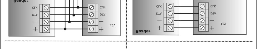


56 Page 56 from 59

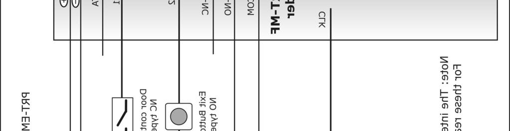

57 Page 57 from 59

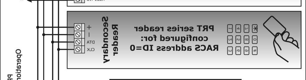
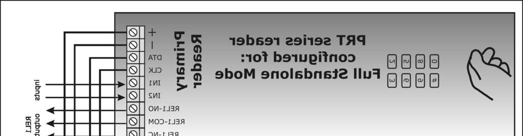
58 Page 58 from 59

59 The symbol of a crossed-through waste bin on wheels means that the product must be disposed of at a separate collection point. This also applies to the product and all accessories marked with this symbol. Products labeled as such must not be disposed of with normal household waste, but should be taken to a collection point for recycling electrical and electronic equipment. Recycling helps to reduce the consumption of raw materials, thus protecting the environment. Contact Roger sp.j Sztum Gościszewo 59 Tel.: Fax: biuro@roger.pl Internet: Page 59 from 59
PRTxxMF series ISO/IEC 14443A and MIFARE readers. Firmware version: x Document version: Rev. H. This document refers to following products:
 PRTxxMF series ISO/IEC 14443A and MIFARE readers Firmware version: x.35.164 Document version: Rev. H This document refers to following products: - PRT12MF - PRT12MF-BK - PRT62MF - PRT64MF - PRT66MF Operating
PRT12 v1.2 RFID/PIN Outdoor Access Terminal
 PRT12 v1.2 RFID/PIN Outdoor Access Terminal Firmware v73.00 Installation and Programming Guide MASCO Biztonságtechnikai és Nyílászáró Automatizálási Kereskedelmi Kft. 1045 Budapest, Madridi út 2. Tel:
PRT42 and PRT42-BK Indoor Access Control Terminals Firmware v72.00
 PRT42 and PRT42-BK Indoor Access Control Terminals Firmware v72.00 Installation and Programming Guide MASCO Biztonságtechnikai és Nyílászáró Automatizálási Kereskedelmi Kft. 1045 Budapest, Madridi út 2.
PRxx1 series controllers Functional Description and Programming Guide
 Roger Access Control System PRxx1 series controllers Functional Description and Programming Guide Document version: Rev.E This document refers to the following products: PR311SE, PR311SE-BK, PR611, PR621,
PRT62 v1.1 Outdoor Access Control Terminal Firmware v74.7
 PRT62 v1.1 Outdoor Access Control Terminal Firmware v74.7 Installation and Programming Guide 1 T ABLE OF C ONTENTS 1 Table of Contents...2 2 General...3 2.1 Designed Function...3 2.2 Features...3 3 Operating
SL2000E. Status Output. Electronic Code Lock. Features. Input. Exit Button Input. Introduction. Door Contact Input. Functional Description.
 SL2000E Electronic Code Lock Features Door Relay output Status transistor output Aux transistor output Door Contact input Exit Button input INSTALLER code for programming MASTER code for arming/disarming
PR402 v1.0 SINGLE DOOR ACCESS CONTROLLER
 PR402 v1.0 SINGLE DOOR ACCESS CONTROLLER FIRMWARE VERSION 117.0 Installation Manual MASCO Biztonságtechnikai és Nyílászáró Automatizálási Kereskedelmi Kft. 1045 Budapest, Madridi út 2. Tel: (06 1) 3904170,
Installation guide for PR302 v2.0 Rev. E
 Installation guide for PR302 v2.0 Rev. E 2016 ROGER sp. z o.o. sp.k. All rights reserved. This document is subject to the Terms of Use in their current version published at the www.roger.pl website of
PR402 v2.0 Installer Manual Rev.C
 PR402 v2.0 Installer Manual Rev.C Introduction This document contents minimum information required for electrical connections, installation and initial tests of PR402 access controller. Installation The
PR602LCD v1.0 Installer Manual Rev. A
 PR602LCD v1.0 Installer Manual Rev. A Introduction This document contents minimum information required for electrical connections and installation of the PR602LCD access controller in Roger Access Control
MCX402DR-BRD I/O expander. Operating Manual
 Roger Access Control System MCX402DR-BRD I/O expander Operating Manual Product version: 1.0 Firmware version: 1.0.2.255 Document version: Rev. B Design and application The MCX402DR-BRD is I/O expander
Installation guide for PR602LCD type access controller
 Roger Access Control System Installation guide for PR602LCD type access controller Firmware version: 1.18.6 or newer Document version: Rev. K 2016 ROGER sp. z o.o. sp.k. All rights reserved. This document
Installation guide for PR612, PR622, PR312EM, PR312EM-BK, PR312MF and PR312MF-BK access controllers
 Roger Access Control System Installation guide for PR612, PR622, PR312EM, PR312EM-BK, PR312MF and PR312MF-BK access controllers Firmware version: 1.18.6 or newer Document version: Rev. G 2016 ROGER sp.
Installation Guide for PR311SE and PR311SE-BK v1.0 Access Controllers Rev. B
 Installation Guide for PR311SE and PR311SE-BK v1.0 Access Controllers Rev. B Introduction This document contains minimum information that is necessary to properly install the device and to perform its
F6-Fingerprint. Access Control/Reader. User Manual. F6 - Simplified Instruction. (Master Code) # (Factory default:1234) Enter the Programming Mode
 # (Factory default:1234) Enter the Programming Mode") -Fingerprint Access Control/Reader Function Description Enter the Programming Mode - Simplified Instruction Operation (Factory default:1234) Change the Master Code Add Fingerprint User Add Card User Add
-Fingerprint Access Control/Reader Function Description Enter the Programming Mode - Simplified Instruction Operation (Factory default:1234) Change the Master Code Add Fingerprint User Add Card User Add
ACTsmart2 Product Range Operating and Installation Instructions
 ACTsmart2 Product Range Operating and Installation Instructions 18-00045 Contents ORDERING INFORMATION......4 INSTALLATION NOTES......5 IMPORTANT......5 PRODUCT SPECIFICATION......5 30 SECOND PROGRAMMING
Rev B ROGER ACCESS CONTROL SYSTEM
 Rev B ROGER ACCESS CONTROL SYSTEM Roger access control solutions Code Locks Readers Access Controllers CPR Network Controllers Communication Interfaces Expanders Power Supply Units Accessories 2 SL2000
MCT82M-IO-CH Operating Manual
 Roger Access Control System MCT82M-IO-CH Operating Manual Product version: 1.0 Document version: Rev. B FUNCTIONAL DESCRIPTION Design and application The MCT82M-IO-CH is an access terminal dedicated to
PRT12MF-DES, PRT84MF and PRT82MF readers. Operating Manual
 Roger Access Control System PRT12MF-DES, PRT84MF and PRT82MF readers Operating Manual Firmware version: v1.0.8 or newer Hardware version: 1.0 Document version: Rev. C This document refers to the following
Proximity Card and Pin Reader Installation Manual
 Multi Prox Proximity Card and Pin Reader Installation Manual PUBLICATION INFORMATION 60A9 - Draft Release Version 0.1.2 71D0 - Version 1.0.5 CONTENTS Introduction... 1 Legend... 2 Terminology... 2 Mounting...
ACCESS CONTROL SYSTEM
 ACCESS CONTROL SYSTEM System versions Standalone controllers series based on integrated models KZ-400, 500, 600, 700, KZC-300,800, 900 KaDe Lite system based on integrated controllers KZ-1000 KaDe Premium
RFT1000 reader in RACS 5. User Manual
 Roger Access Control System RFT1000 reader in RACS 5 User Manual Firmware version: 1.3 or newer Hardware version: 1.1 Document version: Rev. A 2016 ROGER sp. z o.o. sp.k. All rights reserved. This document
DOLXFD1000B. Waterproof Access Control/Reader
 DOLXFD1000B Waterproof Access Control/Reader INTRODUCTION The DOLXFD1000B is a single- entry multi-function Access Controller with integrated keypad and card reader. It is designed and manufactured to
Synergis Master Controller 2.2 Integration Guide for Axis Interface Modules
 Synergis Master Controller 2.2 Integration Guide for Axis Interface Modules This guide supplements the Synergis Master Controller Configuration Guide and explains how to configure Axis interface modules
CV-550SPK V2 Waterproof Keypad/Reader/Controller Installation Instructions
 CV-550SPK V2 Waterproof Keypad/Reader/Controller Installation Instructions Packing List NAME MODEL/SIZE QTY Self tapping screw 0.15 x 1.06 (4mm 27 mm) Rubber plug 0.23 x 1.2 (6mm 30 mm) Star screw driver
UNIVERSAL EXPANDER FOR CARD / CHIP READERS INT-R. 1. Features. 2. Installation and start-up
 UNIVERSAL EXPANDER FOR CARD / CHIP READERS INT-R int-r_en 09/11 The INT-R expander interfaces with the INTEGRA and CA-64 alarm control panels, replacing the previously offered CA-64 SR and CA-64 DR expanders.
IDS X-Series User Manual E Issued June 2013
 1 2 Contents 1. Introduction to the IDS X-Series Panels... 6 2. Before Operating Your Alarm System... 6 3. Understanding the Keypad LEDs... 7 3.1 Viewing Data on an LED Keypad... 11 3.2 Entering Data on
Electronic Code Lock. SL2000E v1.1
 SL2000E v1.1 EN Rev.C.doc 1/29/2008 Electronic Code Lock SL2000E v1.1 Features Door Relay output Status transistor output Aux transistor output Door Contact input Exit Button input INSTALLER code for programming
NX1700EIB02 (Supercedes NX1700EIA02) NetworX Series. NX-1700E Proximity Card Reader Installation and Startup
 NetworX Series. NX-1700E Proximity Card Reader Installation and Startup") NX1700EIB02 (Supercedes NX1700EIA02) NetworX Series NX-1700E Proximity Card Reader Installation and Startup 2002 GE Interlogix All rights reserved. Printed in the United States of America. These instructions
NX1700EIB02 (Supercedes NX1700EIA02) NetworX Series NX-1700E Proximity Card Reader Installation and Startup 2002 GE Interlogix All rights reserved. Printed in the United States of America. These instructions
AC-115 Compact Networked Single-Door Controller Hardware Installation and Programming
 AC-115 Compact Networked Single- Controller Hardware Installation and Programming Copyright 2013 by Rosslare. All rights reserved. This manual and the information contained herein are proprietary to REL,
ATS1190 Smart Card Reader Programming Manual
 ATS1190 Smart Card Reader Programming Manual Version 2.0 Aritech and Tecom are Interlogix Companies 2001 Interlogix B.V.. All rights reserved. Interlogix B.V. grant the right to reprint this manual for
IDS. Users Guide to Keypad Functions S E C U R I T Y MANUAL NO D ISSUED NOVEMBER 2002 VERSION 2.
 INHEP DIGITAL IDS S E C U R I T Y Users Guide to Keypad Functions MANUAL NO. 700-146-01D ISSUED NOVEMBER 2002 VERSION 2.17 Summary of Operation A rm/ disarm [#] + [USER CODE] Quick Quick Quick Away Arm
GETTING STARTED. Installing the System 2000 Hardware. Configuring Your System 2000 Hardware. Troubleshooting. Configuring Your System 2000 Network
 SYSTEM 2000 GETTING STARTED Installing the System 2000 Hardware Whether you are upgrade an existing System 2, or this is a brand new installation, there will be some hardware installation involved. We
Installation and User Manual
 S2 Metal Waterproof Access Control Unit Installation and User Manual (Ness Part No. 101-082) 1 Introduction Ness S2 is an advanced, waterproof (IP65 rated) proximity and PIN Access Controller. S2 can support
XP-KIT. Programming & Operations. Programming Starter Kit for Aiphone -XP Series Proximity Reader Stations
 9800 XP-KIT Programming Starter Kit for Aiphone -XP Series Proximity Reader Stations Programming & Operations Manual KIT CONTENTS: Programming Keypad Programming Master Card Pack 0 Blank Proximity Cards
AS Keypad User Manual
 AS Keypad User Manual Specifications Operating Voltage: 12~24 VAC/DC Current Draw: TBA Input: request-to-exit (for Relay 1) time out reed switch contact (for Relay 1) Output: Relay 1: N.O./N.C./Com. Output
Akcess BioMetrics Corporation. Bio2Touch. Access Control Fingerprint Reader. User's Manual. Akcess BioMetrics Corporation
 Akcess BioMetrics Corporation Bio2Touch Access Control Fingerprint Reader User's Manual Akcess BioMetrics Corporation Notices: Information in this document is subject to change without notice. NO WARRANTY
AC-Q4x Family. Instruction Manual. Vandal Resistant Stand-Alone controllers. Models: AC-Q41H/HB AC-Q41SB AC-Q42H/HB AC-Q42SB AC-Q44
 AC-Q4x Family Vandal Resistant Stand-Alone controllers Instruction Manual ls: AC-Q41H/HB AC-Q41SB AC-Q42H/HB AC-Q42SB AC-Q44 December 2006 Table of Contents Table of Contents 1. General Information...
VANDAL RESISTANT BACK-LIT WEATHERPROOF ACCESS CONTROL KEYPAD
 VANDAL RESISTANT BACK-LIT WEATHERPROOF ACCESS CONTROL KEYPAD Post Mount Keypad Programming & Installation Manual 1. Connect Power 12V DC to 24V AC/DC to terminals (+) and (-) Post Mount Keypad Quick Start
7612 Programming Instructions
 7612 Programming Instructions Built-in Proximity reader Read Range 65mm odulation ASK at 125kHz Compatible Cards ALL 26-Bit EM Cards 7612 is a vandal resistant proximity card and keypad access control
IBA-7612 Programming Instructions
 IBA-7612 Programming Instructions Built-in Proximity reader Read Range 65mm odulation ASK at 125kHz Compatible Cards ALL 26-Bit EM Cards IBA-7612 is a vandal resistant proximity card and keypad access
2000 Series e/em Style Keypad Installation and Programming Manual
 2000 Series e/em Style Keypad Installation and Programming Manual Document Number: 6054022 Revision: 0 Date: 12/21/06 Table of Contents Table of Contents Section 1: Introduction... 6 1 Product Description...6
LIFT CONTROL WITH FLOOR BUTTON FEEDBACK (V3 OR LATER)
") Applications Programming Guide - LIFT CONTROL WITH BUTTON FEEDBACK. Rev 4.51 Page 1 LIFT CONTROL WITH FLOOR BUTTON FEEDBACK (V3 OR LATER) Lift control logic can be used to control Floor security for a
Applications Programming Guide - LIFT CONTROL WITH BUTTON FEEDBACK. Rev 4.51 Page 1 LIFT CONTROL WITH FLOOR BUTTON FEEDBACK (V3 OR LATER) Lift control logic can be used to control Floor security for a
KP2000E/EM Series Style Keypad
 23852973 KP2000E/EM Series Style Keypad Installation and Programming Instructions Models KP2000EXX and KP2000EMXX Specifications Parameter Voltage Requirements Keypad Current Requirements (Max) Relay Contact
BioPointe. User's Manual
 BioPointe User's Manual Getting to know the BioPointe Notices: Information in this document is subject to change without notice. NO WARRANTY OF ANY KIND IS MADE WITH REGARD TO THIS MATERIAL INCLUDING,
A-1300 Biometric Access Control System USER'S MANUAL
 A-1300 Biometric Access Control System USER'S MANUAL Table of Contents 1. General Information... 1 1.0 Notification... 2 1.1 System Overview... 2 1.2 Main Features... 2 1.3 Equipment... 3 2. Basic Concepts...
REX F-0-9 Standalone or Access Controller
 REX F-0-9 Standalone or Access Controller Power supply The controller need s external power supply to operate. The Spider W40 power supply is sufficient to power two controllers and two 12V electric strikes
ROSSLARE AC-115. Hardware Installation and User s Guide DOOR MODE 10/01
 ROSSLARE MODE 1 2 DOOR 3 4 5 6 7 8 9 0 # AC-115 Hardware Installation and User s Guide 10/01 ROSSLARE Hardware Installation and User s Guide for the AC-115 Access Control System MODE 1 2 DOOR 3 4 5 6 7
User Manual RINS1209-5
 User Manual 2x 2x RINS1209-5 The EURO mini Keypad Contents Introduction 1-5 Using EURO mini with PIN Codes 5-9 Intelligent Setting 10-11 When Problems Arise 12 Setting Individual Areas 13-14 Chime Facility
VIS-3200 / VIS-3201 User Manual
 2.4GHz Indoor Black Wireless Exit Button Receiver Keypad / Reader Access Control 500 Users Range of 50 Feet Delay and On/Off Toggle Mode Battery Operated Standalone No Software 1 VIS-3200 / VIS-3201 User
DSC PowerSeries Neo Integration
 DN2120-1015 DSC PowerSeries Neo Integration The purpose of this application note is to explain how to setup the DSC PowerSeries Neo integration with a KT-400 or a KT-1-M (or PCB) using an RS-232 or IP
MCM Electronics MCM Electronics MCM Electronics. The Icon Series. Installation and Programming Information. Icon 8 Version 5.0
 MCM Electronics MCM Electronics MCM Electronics The Icon Series Installation and Programming Information Icon 8 Version 5.0 TABLE OF CONTENTS 1. 2. 3. Panel Hardware Page 2 Physical Layout. Inputs. Outputs.
Access control panel U-Prox IC E (Elevator control)
") 1.003 Access control panel U-Prox IC E (Elevator control) Installation and programming manual About this document http://u-prox.com This manual covers installation, adjustment and use of U-Prox IC E (hereinafter
1.003 Access control panel U-Prox IC E (Elevator control) Installation and programming manual About this document http://u-prox.com This manual covers installation, adjustment and use of U-Prox IC E (hereinafter
Configuring Door and Device Templates
 CHAPTER 8 This chapter describes how to create and modify door and device templates. Device templates define common settings for device types, such as Gateways, readers and locks. Door templates define
First Access Express OPERATOR GUIDE
 First Access Express OPERATOR GUIDE October 2016 Cutting edge simplicity Table of Contents Introduction... 4 PC Requirements... 5 Step 1. Software Installation... 5 Complete Installation Server and Client...
AXS-100. User's Guide. Two-Door Proximity Access Control System (V2.06) DE6280U 1
 DE6280U 1") AXS-100 Two-Door Proximity Access Control System (V2.06) User's Guide Table of Contents 1. INTRODUCTION... 3 2. USER INTERFACE... 3 2.1. Keypad...3 2.2. Idle Screen...3 2.3. Login Screen...4 2.4. Operating
AXS-100 Two-Door Proximity Access Control System (V2.06) User's Guide Table of Contents 1. INTRODUCTION... 3 2. USER INTERFACE... 3 2.1. Keypad...3 2.2. Idle Screen...3 2.3. Login Screen...4 2.4. Operating
W3-H Waterproof Keypad/Reader/Controller
 W3-H Waterproof Keypad/Reader/Controller User Manual 1. Packing list Name Quantity Digital Keypad W3-H 1 User Manual 1 Screw Driver Rubber Bungs Self Tapping Screws Diode 1 4 4 1 Manager Card 2 Remark
ACCESS CONTROLLER S2000-2
 ACCESS CONTROLLER S2000-2 User s Manual WARNING: To change configuration parameters of the controller please use UProg.exe software utility of versions 4.1.0.54 and higher. DO NOT use UProg.exe of versions
2 IDS LCD Keypad User Manual C Issued March 2009
 2 3 4 Contents 1. Introduction to the IDS LCD Digital Keypad...8 2. Arming the Control Panel...8 2.1 Away Arming...8 2.1.1 How to Away Arm...8 2.1.2 Quick Away Arm Shortcut Key...8 2.2 Stay Arming...9
Technical documentation
 Document type: Technical documentation Scope: Galaxy Integration Product: IFTER EQU Prepared: 2015 1 Contents 1.0 IFTER EQU Visualization software 4 2.0 Honeywell Galaxy control units visualization 6 3.0
VIDI-AC-2CS Access Controller/ Reader
 VIDI-AC-2CS Access Controller/ Reader User Manual CONTENTS INTRODUCTION 2 INSTALLATION.4 STANDALONE MODE 6 CONTROLLER MODE.11 WIEGAND READER MODE.. 13 ADVANCE APPLICATION..14 1 INTRODUCTION The VIDI-AC-2CS
Important Notice. Customer Information. 2 WisDom User Manual
 User Manual Important Notice This manual is delivered subject to the following conditions and restrictions: This manual contains proprietary information belonging to RISCO Group. The information is supplied
EVOHD. Programming Guide. Version
 EVOHD Programming Guide Version 1.11 www.paradox.com Warranty For complete warranty information on this product please refer to the Limited Warranty Statement found on our Web site: www.paradox.com. Your
: DOOR ENTRY UNIT. Programming Software USER MANUAL
 : DOOR ENTRY UNIT Programming Software MODELS: EIS-1, EIS-2 OR EIS-4 v.02 2018 Contents 1 FOR YOUR SAFETY...4 2 INTRODUCTION...5 3 EIS-1, EIS-2, EIS-4 FEATURES AND APPLICATIONS...6 4 START UP...7 5 LED
Dryer. M720 Programming and Operation Manual. July 15, 2015 Revision 1.51
 Dryer M720 Programming and Operation Manual July 15, 2015 Revision 1.51 Contents 1 Important Safety Information 1 1.1 FOR YOUR SAFETY - CAUTION!............................. 1 2 Control Overview 2 2.1
Colour Graphic Terminal User Manual. Rev 3.1
 Integriti. Colour Graphic Terminal User Manual. 1 Colour Graphic Terminal User Manual. Rev 3.1 2013-2014. Inner Range Pty. Ltd. Part Number: 636000U 2 Integriti. Revision 3.1 June 2014. SYSTEM DETAILS
RFID PRODUCT AND SYSTEM
 EL500(T)-X-XX Access control system, EM125kHz technology EL500-X-0C EL500-X-1C EL500-X-0D Economic access control system, EM125kHz technology Economic access control system, EM125kHz technology, with keypad
INSTALLATION INSTRUCTIONS 920P EntryCheck TM
 801 Avenida Acaso, Camarillo, Ca. 93012 (805) 494-0622 www.sdcsecurity.com E-mail: service@sdcsecurity.com INSTALLATION INSTRUCTIONS 920P EntryCheck TM The EntryCheck 920P Indoor/Outdoor Keypad is a surface-mount
AYC-Ex5/T65 Family Convertible Backlit Proximity & PIN Readers/Controllers Installation and Programming Manual
 AYC-Ex5/T65 Family Convertible Backlit Proximity & PIN Readers/Controllers Installation and Programming Manual Ex5 Models: AYC-E55 AYC-E65BB AYC-E65BG AYC-E65BW T65 Models: AYC-T65B AYC-T65N AYC-Ex5 AYC-T65
pro ACTpro IOM INPUT/OUTPUT MODULE Installation and Configuration Instructions for the ACTpro IOM Input/Output Module ACT Product Code: ACTPRO IOM
 pro ACTpro IOM INPUT/OUTPUT MODULE Installation and Configuration Instructions for the ACTpro IOM Input/Output Module ACT Product Code: ACTPRO IOM pro CONTENTS Technical Specification... 4 Product Overview...
Aperio Online Quick Installation Guide
 Aperio Online Quick Installation Guide Document No: ST-001322-B, Issue date: 11 October 2013 The global leader in door opening solutions Table of Contents 1 Introduction... 3 Purpose...3 Scope...3 Applicable
SK-3133-PPQ Heavy-Duty Outdoor Access Control Keypad with Proximity Reader
 SK-3133-PPQ Heavy-Duty Outdoor Access Control Keypad with Proximity Reader Features: Rugged construction heavy-duty stainless steel faceplate with coated steel housing Built-in proximity card reader 12~24
EUROPLEX TECHNOLOGIES. WARNING. Copyright. Disclaimer
 EUROPLEX TECHNOLOGIES. Company Web Site address: www.europlex.com Europlex Technologies [Ireland] Ltd. Clonshaugh Industrial Estate, Clonshaugh, Dublin 17, Ireland. Tel: +353-1 - 8485111 Fax: +353-1 -
180 Series Keypad. Handbook. Revision 2.1
 180 Series Keypad Handbook Revision 2.1 Revision History Revision 1.0 Initial release Revision 2.0 Major update with addition of 180-40 Added 180-40 to document and various headings Note regarding unique
AYC-F/G/M60 Family Backlit goprox & PIN Reader Convertible Series with Genuine HID Technology Installation and Programming Manual
 AYC-F/G/M60 Family Backlit goprox & PIN Reader Convertible Series with Genuine HID Technology Installation and Programming Manual AYC-F60 AYC-G60 AYC-M60 Copyright 2013 by Rosslare. All rights reserved.
Series. NX-8-EUR Control Panel. Installation manual
 g GE Security NetworX TM Series NX-8-EUR Control Panel Installation manual NX-8-EUR Installation manual Page 2 23/12/04 CONTENTS CONTENTS...3 GENERAL INFORMATION...5 ORDERING INFORMATION...5 FEATURE DEFINITIONS...6
AYC-E/Q/T60 Family Backlit goprox & PIN Reader Convertible Series with Genuine HID Technology Installation and Programming Manual
 AYC-E/Q/T60 Family Backlit goprox & PIN Reader Convertible Series with Genuine HID Technology Installation and Programming Manual AYC-E60 AYC-Q60 AYC-T60 Copyright 2013 by Rosslare. All rights reserved.
QUICK CONSUMER REFERENCE GUIDE
 QUICK CONSUMER REFERENCE GUIDE YOUR SYSTEM: ADT PM33 Commercial System Starting to use the Alarm Panel and Keypad PM33 Control Panel KP-250 PG2 Keypad Keyfob Setting Your System Step 1 When leaving your
INSTALLATION INSTRUCTIONS 921P EntryCheck TM
 80 Avenida Acaso, Camarillo, Ca. 90 (805) 494-06 www.sdcsecurity.com E-mail: service@sdcsecurity.com INSTALLATION INSTRUCTIONS 9P EntryCheck TM The EntryCheck 9P Indoor/Outdoor Keypad is a surface mount
INSTALLATION INSTRUCTIONS 920 EntryCheck TM
 801 Avenida Acaso, Camarillo, Ca. 93012 (805) 494-0622 www.sdcsecurity.com E-mail: service@sdcsecurity.com INSTALLATION INSTRUCTIONS 920 EntryCheck TM The EntryCheck 920 Indoor/Outdoor Keypad is a surface-mount
Installation Instructions
 Alliance Arming Station AL-1111, AL-1116 1048520C September 2006 Copyright 2006, GE Security Inc. Introduction This is the GE Alliance Arming Station for models AL-1111 (four-line LCD) and AL-1116 (four-line
DAS 250L CONTROL COMMUNICATOR INSTALLATION MANUAL
 DAS 250L CONTROL COMMUNICATOR INSTALLATION MANUAL TABLE OF CONTENTS 1. GENERAL DESCRIPTION... P.2 2. STANDARD AND OPTIONAL PARTS LIST..... P.2 3. FEATURE DEFINITIONS... P.3 4. TERMINAL DRAWING AND SPECIAL
AC-Q4x Family Anti-Vandal Standalone Controllers Installation and Programming Manual
 AC-Q4x Family Anti-Vandal Standalone Controllers Installation and Programming Manual ls: AC-Q41H/HB AC-Q41HP AC-Q41SB AC-Q42H/HB AC-Q42HP AC-Q42SB AC-Q44 Copyright 2014 by Rosslare. All rights reserved.
DG-800 Stand-Alone Proximity Reader Instruction Manual
 DG-800 Stand-Alone Proximity Reader Instruction Manual I. Features 1. Memory volume up to 1000+10 proximity cards/tokens and PINs with the programming time up to 0.5 seconds. 2. Access modes: a. Only Proximity
IRIS-Config-Manual-1a
 Configuration Manual Table of contents The IRIS Base module 1 The IRIS system 2 The IRIS configuration program 3 Project 3 Create a project 3 Unit 3 Create a unit 3 Delete a unit 4 Export 4 Import 4 Setup
EntryProx Quick Start Guide
 This guide provides quick info on how to add or delete cards, print transactions, and change the main relay timer. For installation details or advanced programming, see the complete user s guide, part
W3-M. Metal waterproof standalone access control/reader. User Manual
 W3M Metal waterproof standalone access control/reader User Manual Name Digital Keypad W3M User Manual Screw driver Rubber bungs Selftapping screws Diode 1. Packing List Quantity 1 1 1 4 4 1 Remark 6*27mm,
MULTI-PURPOSE SELF-CONTAINED DIGITAL ACCESS CONTROL KEYPAD
 MULTI-PURPOSE SELF-CONTAINED DIGITAL ACCESS CONTROL PAD Programming & Installation Manual An Innovative Product Developed By: PROTECT - ON SYSTEMS LTD. MANUFACTURED BY: 20 R SINCE 1979 ADVANCED ELECTRONICS
Portals 14 What is a portal? 14 Hardware 15 RS232 to RS USB to RS TCP/IP to RS Add a Serial Portal 16 Add a Network portal 16
 PROS LITE User Manual Version 2.0.0 www.visual-plus.com Table of Contents Getting Started 5 Starting PROS Lite 5 Create a Portal 5 Adding a control panel 6 Adding a user 7 Upload users to a controller
Aperio Programming Application Manual
 Aperio Programming Application Manual Document No: ST-001321-E, Issue date: 1 August 2014 1 The global leader in Aperio Online Programming Application Manual, Document No: ST-001321-E Date: 1 augusti 2014
Installation & User Manual V2.08
 YOUR SECURITY IS OUR PRIORITY Other products from GSD Contents Installation Instructions Installation Diagrams System Overview Wiring Diagrams Network Diagrams Operation Instructions Fingerprint Enrollment
INT-TSI Brief User Manual
 int-tsi_u_en 03/15 Keypad INT-TSI Brief User Manual SATEL sp. z o.o. ul. Budowlanych 66 80-298 Gdańsk POLAND tel. 58 320 94 00 info@satel.pl www.satel.eu Firmware version 1.04 WARNINGS Please read this
2 4PI175 issue 1_6/01. How to unset system in alarm. Programs 1, 2 and 3. Access codes. How to operate Personal Attack
 Access codes Contents Unset system indications - - - - - - - - - - - System indication - - - - - - - - - - - - Access codes - - - - - - - - - - - - - - - - How to operate Personal - - - - - - How to unset
to that area and whether or not the Cardax FT GBUS URI (Standard or person holds these competencies. Wiegand variant)
") The Cardax FT Controller 6000 is a powerful modular, intelligent field controller for processing, storing and communicating large amounts of data in real time, independently of the Cardax FT Command Centre
The Cardax FT Controller 6000 is a powerful modular, intelligent field controller for processing, storing and communicating large amounts of data in real time, independently of the Cardax FT Command Centre
PR MASTER USER MANUAL
 PR MASTER USER MANUAL PRM Version 4.5.18 Rev. L Contents I. Introduction...5 Chapter 1. Preparing system to work...7 1.1 PR Master Installation...7 1.1.1. Roger ACS 4.5 application group content... 11
Contents. 4. Disarming the Control Panel How to Disarm with a User Code How to Disarm using a Key-Switch or Remote...
 Contents 1. Introduction to the Watchguard WGAP864 LCD Digital Keypad... 6 2. Viewing Violated Zones... 6 3. Arming the Control Panel... 7 3.1 Away Arming... 7 3.1.1 How to Away Arm... 7 3.1.2 Quick Away
REMOTE KEYPAD with NFC Tag (KPT-32N, KPT-32N-F1)
") REMOTE KEYPAD with NFC Tag (KPT-32N, KPT-32N-F1) April 01st, 2016 Identifying the Parts 1. Siren 2. Orange LED: Home Arm Key 3. Red LED: Away Arm Key 4. Panic Alarm (if enabled) - Press both 1 and 3 to
REMOTE KEYPAD with NFC Tag (KPT-32N, KPT-32N-F1) April 01st, 2016 Identifying the Parts 1. Siren 2. Orange LED: Home Arm Key 3. Red LED: Away Arm Key 4. Panic Alarm (if enabled) - Press both 1 and 3 to
AD-300 AD-301. Networked hardwired lock user guide Instructions for adaptable series networked hardwired locks
 *P516-128* P516-128 AD-300 AD-301 Networked hardwired lock user guide Instructions for adaptable series networked hardwired locks Para el idioma español, navegue hacia www.allegion.com/us. Pour la portion
User Manual. Split access control with intelligent secured power supply.
 User Manual Split access control with intelligent secured power supply. Contents. Introduction, features and specifications. Installation and Wiring Diagram 3. Manager Card Operation 4. User Settings 5.
: DOOR ENTRY UNIT USER MANUAL EIS-LCD. Programming Software
 : DOOR ENTRY UNIT EIS-LCD Programming Software v.2.0 2018 Page 1 Contents 1 FOR YOUR SAFETY...5 2 INTRODUCTION...6 3 EIS-LCD, EIS-40 FEATURES AND APPLICATIONS...7 4 START UP...8 5 LED INDICATION...9 6