VDE Testing and Certification Institute
|
|
|
- Martha Melton
- 6 years ago
- Views:
Transcription
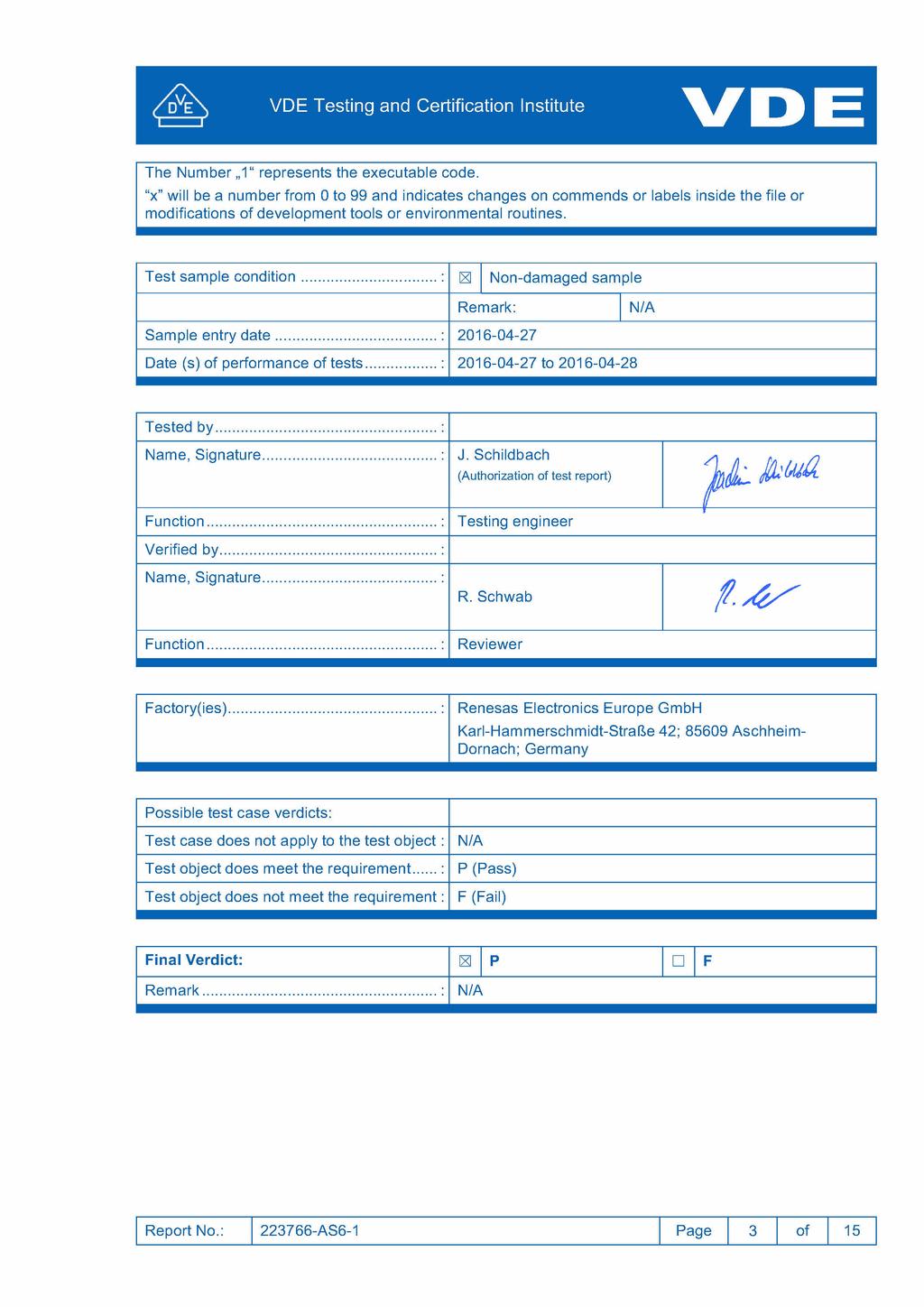
1 Test Report Report No.... : AS6-1 File No.... : / Date of issue... : Laboratory... : Testing and Certification Institute Address... : Merianstrasse Offenbach/Main; Germany Testing location/ address... : rüf- und Zertifizierungsinstitut GmbH Testing and Certification Institute Merianstrasse 28, Offenbach, Germany Applicant's name... : Renesas Electronics Europe GmbH Applicant's address... : Karl-Hammerschmidt-Straße 42; Aschheim- Dornach; Germany Applied standard(s)... : DIN EN ( ): ; EN :2012 DIN EN Ber.1 ( Ber.1): ; EN :2012/AC:2014 EN :2012/A11:2014 DIN EN ( ): ; EN :2011 IEC (ed.5);am1 IEC (ed.5) ;am1 Test item description... : Self-Diagnostic Routines for Micro controller Family S7 Trade Mark... : Renesas Type reference(s)... : File Name Revision cpu_test.c 1.x CU_Test_Control.asm 1.x cpu_test_coupling.c 1.x CU_Test_General_High.asm 1.x CU_Test_General_Low.asm 1.x fpu_control.asm 1.x fpu_exten.asm 1.x fpu_test_coupling.c 1.x TestFUCouplingEnd.asm 1.x TestFUCouplingStart_A.asm 1.x TestFUCouplingStart_B.asm 1.x TestGRsCouplingEnd.asm 1.x TestGRsCouplingStart_A.asm 1.x TestGRsCouplingStart_B.asm 1.x Report No.: AS6-1 age 1 of 15 Disclaimer: This test report contains the result of a singular investigation carried out on the product submitted. A sample of this product was tested to found the accordance with the thereafter listed standards or clauses of standards resp. The test report does not entitle for the use of a Certification Mark and considers solely the requirements of the specifications mentioned below. Whenever reference is made to this test report towards third party, this test report shall be made available on the very spot in full length.
2 TestFUCouplingS0_S3_A.asm 1.x TestFUCouplingS0_S3_B.asm 1.x TestFUCouplingS4_S7_A.asm 1.x TestFUCouplingS4_S7_B.asm 1.x TestFUCouplingS8_S11_A.asm 1.x TestFUCouplingS8_S11_B.asm 1.x TestFUCouplingS12_S15_A.asm 1.x TestFUCouplingS12_S15_B.asm 1.x TestFUCouplingS16_S19_A.asm 1.x TestFUCouplingS16_S19_B.asm 1.x TestFUCouplingS20_S23_A.asm 1.x TestFUCouplingS20_S23_B.asm 1.x TestFUCouplingS24_S27_A.asm 1.x TestFUCouplingS24_S27_B.asm 1.x TestFUCouplingS28_S31_A.asm 1.x TestFUCouplingS28_S31_B.asm 1.x TestGRsCouplingR0_A.asm 1.x TestGRsCouplingR0_B.asm 1.x TestGRsCouplingR1_R3_A.asm 1.x TestGRsCouplingR1_R3_B.asm 1.x TestGRsCouplingR4_R6_A.asm 1.x TestGRsCouplingR4_R6_B.asm 1.x TestGRsCouplingR7_R9_A.asm 1.x TestGRsCouplingR7_R9_B.asm 1.x TestGRsCouplingR10_R12_A.asm 1.x TestGRsCouplingR10_R12_B.asm 1.x clock_monitor.c 1.x crc.c 1.x CRC_Verify.c 1.x ramtest_march_c.c 1.x ramtest_march_c_hw.c 1.x ramtest_march_hw.c 1.x ramtest_march_x_wom.c 1.x ramtest_march_x_wom_hw.c 1.x test_adc12.c 1.x Ratings... : Supplementary information: Report No.: AS6-1 age 2 of 15
3
4 Environmental conditions (if applicable) Ambient temperature Atmospheric pressure Relative humidity Rated values... : C ha % Verified values... : Range confirmed by: Deutscher Wetterdienst (Meteorological service) Report No.: AS6-1 age 4 of 15
5 erformed tests TABLE R.1 / Table H.1 for software class R.1 / B GENERAL FAULT / ERROR CONDITIONS Component 1) Fault/error Acceptable Definitions Document measures 2) 3) 4) reference Document reference Verdict for applied measure for applied test 1 CU 1.1 Register Stuck at Functional test, or periodic self-test using either: static memory test, or word protection with single bit redundancy H H H H SWD_003_1_A015 _1.0_SW Design Documentation_for_ SWV_002_A015 _1.0_SW Verification report_for_ 1.2 Void 1.3 rogramme counter Stuck at Functional test, or H periodic self-test, or H independent time-slot monitoring, or H logical monitoring of the programme sequence H Interrupt handling and execution No interrupt or too frequent interrupt Functional test; or time-slot monitoring H H Clock Wrong frequency (for quartz synchronized clock: harmonics/ subharmonics only) Frequency monitoring, or time slot monitoring H H SWD_003_1_A015 _1.0_SW Design Documentation_for_ SWV_002_A015 _1.0_SW Verification report_for_ 4 Memory 4.1 Invariable memory All single bit faults eriodic modified checksum; or multiple checksum, or H H SWD_003_1_A015 _1.0_SW Design Documentation_for_ SWV_002_A015 _1.0_SW Verification report_for_ word protection with single bit redundancy H Variable memory DC fault eriodic static memory test, or word protection with single bit redundancy H H SWD_003_1_A015 _1.0_SW Design Documentation_for_ SWV_002_A015 _1.0_SW Verification report_for_ Report No.: AS6-1 age 5 of 15
6 4.3 Addressing (relevant to variable and invariable memory) Stuck at Word protection with single bit parity including the address H Covered by 1.1; 3; 4.1; 4.2 and 5 Internal data path 5.1 Data Stuck at Word protection with single bit redundancy H Addressing Wrong address Word protection with single bit redundancy including the address H External communication 6.1 Data Hamming distance 3 Word protection with multi-bit redundancy, or CRC single word, or H H transfer redundancy, or H protocol test H Void 6.3 Timing Wrong point in time Time-slot monitoring, or scheduled transmission H H Time-slot and logical monitoring, or H comparison of redundant communication channels by either: reciprocal comparison H independent hardware comparator H Wrong sequence Logical monitoring, or time-slot monitoring, or H H scheduled transmission H (same options as for wrong point in time) 7. Input/output 7.1 Digital I/O Fault conditions specified in lausibility check H Analog I/O Report No.: AS6-1 age 6 of 15
7 7.2.1 A/D- and D/Aconverter Analog multiplexer 8. Void 9 Custom chips. ASIC, GAL, Gate array Fault conditions specified in Wrong addressing Any output outside the static and dynamic functional specification Supplementary information: */* lausibility check H SWD_003_1_A015 _1.0_SW Design Documentation_for_ lausibility check eriodic self-test H H SWV_002_A015 _1.0_SW Verification report_for_ To 1.1 Registers: The routines include stuck-at and coupling failure detection. The user can set stuck-at detection only or stuck plus coupling failure detection. To 1.3 rogram Counter In the routines for register test 1.1 a small routine for testing of program counter is integrated. This routine does not cover completely the requirement of standard. It is a support for measures referenced in the table above. Additional measures Details Reference Verdict Watch Dog test Fail Trigger and Rest Source Monitoring Stack ointer Register and Stack Memory Test Write-read-verify with pattern for register and March-C for memory SWD_003_1_A015 _1.0_SW Design Documentation_for_ and SWV_002_A015 _1.0_SW Verification report_for_ Additional hardware features rotection Reference Verdict Ram parity error detection Stuck at or illegal modification - any access to undefined memory - write access to invariable Invalid memory access detection memory (ROM) function - instruction fetch from special predefined memory areas Window Watch dog with independent clock ort Output Enable On Chip Temperature Voltage Monitoring - Loss of clock of the arithmetic logical unit (ALU) or the complete micro controller - permanent execution of an undefined endless loop - permanent undefined code execution ( runaway software ) - time slot monitoring Set WM outputs to High- Impedance when failure is indicated from external or detected by software Over Temperature for Silicon Device Under voltage detection to avoid unstable operation r01um0001eu0080_synergy_s7g2.pdf Report No.: AS6-1 age 7 of 15
8 Clause Requirement + Test Result Remark Verdict R ANNEX R (NORMATIVE) ( ) SOFTWARE EVALUATION rogrammable electronic circuits requiring software incorporating measures to control the fault/error conditions specified in table R.1 or R.2 validated in accordance with the requirements of this annex Self-test routines for software of class R.1 R.1 rogrammable electronic circuits using software rogrammable electronic circuits requiring software incorporating measures to control the fault/error conditions specified in table R.1 or R.2 constructed so that the software does not impair compliance with the requirements of this standard R.2 Requirements for the architecture R rogrammable electronic circuits requiring software incorporating measures to control the fault/error conditions specified in table R.1 or R.2 use measures to control and avoid software-related faults/errors in safety-related data and safety-related segments of the software rogrammable electronic circuits requiring software incorporating measures to control the fault/error conditions specified in table R.2 have one of the following structures: - single channel with periodic self-test and monitoring - dual channel (homogenous) with comparison - dual channel (diverse) with comparison rogrammable electronic circuits requiring software incorporating measures to control the fault/error conditions specified in table R.1 have one of the following structures: - single channel with functional test - single channel with periodic self-test - dual channel without comparison R.2.2 Measures to control faults/errors R R R When redundant memory with comparison is provided on two areas of the same component, the data in one area is stored in a different format from that in the other area rogrammable electronic circuits with functions requiring software incorporating measures to control the fault/error conditions specified in table R.2 and that use dual channel structures with comparison, have additional fault/error detection means for any fault/errors not detected by the comparison For programmable electronic circuits with functions requiring software incorporating measures to control the fault/error conditions specified in table R.1 or R.2, means are provided for the recognition and control of Report No.: AS6-1 age 8 of 15
9 errors in transmissions to external safety-related data paths R For programmable electronic circuits with functions requiring software incorporating measures to control the fault/error conditions specified in table R.1 or R.2, the programmable electronic circuits incorporate measures to address the fault/errors in safety-related segments and data indicated in table R.1 and R.2 as appropriate R For programmable electronic circuits with functions requiring software incorporating measures to control the fault/error conditions specified in table R.1 or R.2, detection of a fault/error occur before compliance with clause 19 is impaired Self-test routines only; compliance to clause 19 has to be insured by the user of the self-test routines R The software is referenced to relevant parts of the operating sequence and the associated hardware functions R Labels used for memory locations are unique R The software is protected from user alteration of safety-related segments and data R Software and safety-related hardware under its control is initialized and terminates before compliance with clause 19 is impaired Self-test routines only; compliance to clause 19 has to be insured by the user of the self-test routines R.3 Measures to avoid errors R.3.1 General For programmable electronic circuits with functions requiring software incorporating measures to control the fault/error conditions specified in table R.1 or R.2, the following measures to avoid systematic fault in the software are applied Software that incorporates measures used to control the fault/error conditions specified in table R.2 is inherently acceptable for software required to control the fault/error conditions specified in table R.1 Class R.1 only R.3.2 Specification R Software safety requirements: Software Id: 1.x The specification of the software safety requirements includes the descriptions listed R Software architecture R The specification of the software architecture includes the aspects listed See table R.1 - techniques and measures to control software faults/errors (refer to R.2.2); - interactions between hardware and software; - partitioning into modules and their allocation to the specified safety functions; Report No.: AS6-1 age 9 of 15
10 R hierarchy and call structure of the modules (control flow); - interrupt handling; - data flow and restrictions on data access; - architecture and storage of data; - time-based dependencies of sequences and data The architecture specification is validated against the specification of the software safety requirements by static analysis R Module design and coding R Based on the architecture design, software is suitably refined into modules Software module design and coding is implemented in a way that is traceable to the software architecture and requirements R Software code is structured R Coded software is validated against the module specification by static analysis The module specification is validated against the architecture specification by static analysis Reviews and source code walk through R Software validation The software is validated with reference to the requirements of the software safety requirements specification Compliance is checked by simulation of: - input signals present during normal operation - anticipated occurrences - undesired conditions requiring system action H Measures to avoid errors ( ) H For controls with software Class B or C the V-model for the software life cycle should be applied Measures used for software class C are inherently acceptable for software class B Other methods are possible if they incorporate disciplined and structured processes including design and test phases Class B Remark: Software self-diagnostics are made of functions to be executed one by one in series, there are no complex relationships and interactions to consider. Report No.: AS6-1 age 10 of 15
11 H Specification H Software safety requirements H The specification of the software safety requirements includes: H H H H A description of each safety related function to be implemented, including its response time(s): o functions related to the application including their related software classes o functions related to the detection, annunciation and management of software or hardware faults A description of interfaces between software and hardware A description of interfaces between any safety and non-safety related functions Software architecture The description of software architecture shall include the following aspects: Techniques and measures to control software faults/errors (refer to H ) Interactions between hardware and software artitioning into modules and their allocation to the specified safety functions Hierarchy and call structure of the modules (control flow) Interrupt handling Data flow and restrictions on data access Architecture and storage of data Time based dependencies of sequences and data The architecture specification shall be verified against the specification of the software safety requirements by static analysis. Acceptable methods are: Control flow analysis Data flow analysis Walk-throughs / design reviews Based on the architecture design, software is suitably refined into modules. Software module design and coding are implemented in a way that is traceable to the software architecture and requirements H Software code is structured H Coded software is verified against the module specification, and the module specification is verified against the architecture specification by static analysis H Design and coding standards MISRA rogram design and coding standards is consequently used during software design and maintenance Coding standards specify programming practice, proscribe unsafe language features, and specify Report No.: AS6-1 age 11 of 15
12 H procedures for source code documentation as well as for data naming conventions Testing H Module design (software system design, software module design and coding) H H A test concept with suitable test cases is defined based on the module design specification. Each software module is tested as specified within the test concept H Test cases, test data and test results are documented H H H H Code verification of a software module by static means includes such techniques as software inspections, walk-throughs, static analysis and formal proof Code verification of a software module by dynamic means includes functional testing, white-box testing and statistical testing Software integration testing A test concept with suitable test cases is defined based on the architecture design specification The software is tested as specified within the test concept H Test cases, test data and test results are documented H H H Software validation A validation concept with suitable test cases is defined based on the software safety requirements specification The software is validated with reference to the requirements of the software safety requirements specification as specified within the validation concept. The software is exercised by simulation or stimulation of: input signals present during normal operation anticipated occurrences undesired conditions requiring system action H Test cases, test data and test results are documented H H H H H Other Items Tools, programming languages are assumed to be suitable if they comply with "increased confidence from use" according to IEC , C.4.4 Management of software versions: All versions are uniquely identified for traceability Software modification Software modifications are based on a modification request which details the following: the hazards which may be affected Report No.: AS6-1 age 12 of 15
13 H H the proposed change the reasons for change An analysis is carried out to determine the impact of the proposed modification on functional safety. A detailed specification for the modification is generated including the necessary activities for verification and validation, such as a definition of suitable test cases H The modification are carried out as planned H The assessment of the modification is carried out based on the specified verification and validation activities. This may include: a reverification of changed software modules a reverification of affected software modules a revalidation of the complete system H All details of modification activities are documented H Supplementary information: For class C control functions: One of the combinations (a p) of analytical measures given in the columns of table H.9 is used during hardware development... : The self-diagnostic routines mentioned under I are foreseen for following measures of table R.1 / H.1 of. File Name cpu_test.c CU_Test_Control.asm cpu_test_coupling.c CU_Test_General_High.asm CU_Test_General_Low.asm fpu_control.asm fpu_exten.asm fpu_test_coupling.c TestFUCouplingEnd.asm TestFUCouplingStart_A.asm TestFUCouplingStart_B.asm TestGRsCouplingEnd.asm TestGRsCouplingStart_A.asm TestGRsCouplingStart_B.asm TestFUCouplingS0_S3_B.asm TestFUCouplingS4_S7_A.asm TestFUCouplingS4_S7_B.asm TestFUCouplingS8_S11_A.asm Measure 1.1 CU Register Report No.: AS6-1 age 13 of 15
14 TestFUCouplingS8_S11_B.asm TestFUCouplingS12_S15_A.asm TestFUCouplingS12_S15_B.asm TestFUCouplingS16_S19_A.asm TestFUCouplingS16_S19_B.asm TestFUCouplingS20_S23_A.asm TestFUCouplingS20_S23_B.asm TestFUCouplingS24_S27_A.asm TestFUCouplingS24_S27_B.asm TestFUCouplingS28_S31_A.asm TestFUCouplingS28_S31_B.asm TestGRsCouplingR0_A.asm TestGRsCouplingR0_B.asm TestGRsCouplingR1_R3_A.asm TestGRsCouplingR1_R3_B.asm TestGRsCouplingR4_R6_A.asm TestGRsCouplingR4_R6_B.asm TestGRsCouplingR7_R9_A.asm TestGRsCouplingR7_R9_B.asm TestGRsCouplingR10_R12_A.asm TestGRsCouplingR10_R12_B.asm clock_monitor.c crc.c CRC_Verify.c ramtest_march_c.c ramtest_march_c_hw.c ramtest_march_hw.c ramtest_march_x_wom.c ramtest_march_x_wom_hw.c test_adc12.c 3. Clock 4.1 invariable memory 4.2 variable memory A/D- and D/A- converter Report No.: AS6-1 age 14 of 15


15 hoto documentation: Test Setup Testing and measuring equipment: Editor: IAR Embedded Workbenchfor ARM, v IAR Embedded Workbench Common Components, v. 7.2 Compiler/Linker: IAR Embedded Workbenchfor ARM, v IAR Embedded Workbench Common Components, v. 7.2 Debugger: IAR Embedded Workbenchfor ARM, v IAR Embedded Workbench Common Components, v. 7.2 Hardware: Renesas DK-S7G2 Development Kit for Synergy S7 Uncertainty of measurement (optional according to sub-clause c of IEC 17025): END OF TEST REORT Report No.: AS6-1 age 15 of 15
VDE Testing and Certification Institute
 Test Report Report No.... : 240808-TL5-1 File No.... : 5009141-4970-0001/240808 Date of issue... : 2018-03-21 Laboratory... : Testing and Certification Institute Address... : Merianstrasse 28 63069 Offenbach/Main;
VDE Prüf- und Zertifizierungsinstitut GmbH / VDE Testing and Certification Institute. VDE Prüfbericht / VDE Test Report AS
 rüf- und Zertifizierungsinstitut GmbH / rüfbericht / Test Report rüfbericht Nr. Report No.... : -Aktenzeichen File No.... : Ausstellungsdatum Date issue... : Labor Laboratory... : Adresse Address... :
IECEE OPERATIONAL DOCUMENT
 IECEE OD-2045 Edition 2.0 2018-06-05 IECEE OPERATIONAL DOCUMENT IEC System of Conformity Assessment Schemes for Electrotechnical Equipment and Components (IECEE System) Guideline Document & Work Instruction
88 Dugald Campbell. Making Industrial Systems Safer Meeting the IEC standards
 88 Dugald Campbell Making Industrial Systems Safer Meeting the IEC 60730 standards Introduction With the introduction of the International Electrotechnical Commission s IEC 60730 standards series, household
Safety and Reliability of Software-Controlled Systems Part 14: Fault mitigation
 Safety and Reliability of Software-Controlled Systems Part 14: Fault mitigation Prof. Dr.-Ing. Stefan Kowalewski Chair Informatik 11, Embedded Software Laboratory RWTH Aachen University Summer Semester
Assessment of Safety Functions of Lignite Mining Equipment according to the requirements of Functional Safety.
 Assessment of Safety Functions of Lignite Mining Equipment according to the requirements of Functional Safety. Implementation of the Machinery Directive based on proven-in-use, company standards and regulations.
Lecture 2 Microcomputer Organization: Fig.1.1 Basic Components of Microcomputer
 Lecture 2 Microcomputer Organization: As discussed in previous lecture microprocessor is a central processing unit (CPU) with its related timing functions on a single chip. A microprocessor combined with
VDE Prüf- und Zertifizierungsinstitut GmbH / VDE Testing and Certification Institute. VDE Prüfbericht / VDE Test Report. 26 Report No.
 rüf- und Zertifizierungsinstitut GbH / rüfbericht / Test Report rüfbericht Nr. Report No.... : -Aktenzeichen File No.... : 5007383-4970-0007/240201 Ausstellungsdatu Date issue... : 2017-07-28 Labor Laboratory...
TYPE APPROVAL CERTIFICATE
 TYPE APPROVAL CERTIFICATE Certificate No: TAA000011N This is to certify: That the Programmable Electronic System with type designation(s) HIMA HIMAX and Planar4 System Issued to HIMA Paul Hildebrandt GmbH
Report. Certificate Z AC500-S
 Report on the Certificate Z10 15 04 83652 005 AC500-S Manufacturer: ABB Automation Products GmbH ACP Eppelheimer Straße 82 69123 Heidelberg Deutschland Report no. Revision 1.4 of 2016-09-19 Test Body Rail
AI-917-A0. Analogue Input Module (4x 0-20 ma)
") General Specifications GS48D17A00-00E-N AI-917-A0 Analogue Input Module (4x 0-20 ma) GENERAL Figure 1 This module has four analogue inputs and four logic pulse outputs. AI-917-A0 Analogue Input Module
General Specifications GS48D17A00-00E-N AI-917-A0 Analogue Input Module (4x 0-20 ma) GENERAL Figure 1 This module has four analogue inputs and four logic pulse outputs. AI-917-A0 Analogue Input Module
AN3181 Application note Guidelines for obtaining IEC60335 Class B certification in an STM8 application Introduction
 Application note Guidelines for obtaining IEC60335 Class B certification in an STM8 application Introduction Safety plays an increasingly important role in electronics hardware and software applications.
Software architecture in ASPICE and Even-André Karlsson
 Software architecture in ASPICE and 26262 Even-André Karlsson Agenda Overall comparison (3 min) Why is the architecture documentation difficult? (2 min) ASPICE requirements (8 min) 26262 requirements (12
Report. Certificate M6A SIMATIC S7 Distributed Safety
 Report to the Certificate M6A 17 05 67803 014 Safety-Related Programmable Systems SIMATIC S7 Distributed Safety Manufacturer: Siemens AG DF FA AS Gleiwitzer Str. 555 D-90475 Nürnberg Revision 3.1 dated
TYPE APPROVAL CERTIFICATE
 TYPE APPROVAL CERTIFICATE Certificate No: TAA000016N This is to certify: That the Peripheral Equipment with type designation(s) JUMO mtron T Issued to JUMO GmbH & Co. KG Fulda Hessen, Germany is found
Hiperface DSL Combined with Safety
 International TÜV Rheinland Symposium in China Functional Safety in Industrial Applications 18 19 October 2011, Shanghai - China Hiperface DSL Combined with Safety 1 Safety Implementation Hiperface DSL
PSoC 4 IEC Class B and IEC SIL Safety Software Library
 < PSoC 4 IEC 60730 Class B and IEC 61508 SIL Safety Software Library AN89056 Authors: Vasyl Parovinchak, Taras Kuzo Associated Project: Yes Associated Part Family: CY8C40xx, CY8C41xx, CY8C42xx, CY8C42xx-M
Getting Started with the Agilent Serial BERT N4906B. You only need a few minutes to get started with the Serial BERT.
 Getting Started with the Agilent Serial BERT N4906B You only need a few minutes to get started with the Serial BERT. This Getting Started Brochure helps you to quickly understand the operating principles
DAkkS Who we are. Attesting competence, Assuring quality, Creating confidence.
 DAkkS Who we are Attesting competence, Assuring quality, Creating confidence. What is accreditation? Reliability through conformity assessment The demands on the quality of goods and services are growing
MANUAL Functional Safety
 PROCESS AUTOMATION MANUAL Functional Safety Switch Amplifier HiC283* ISO9001 2 With regard to the supply of products, the current issue of the following document is applicable: The General Terms of Delivery
Report. Certificate Z Rev. 00. SIMATIC Safety System
 Report to the Certificate Z10 067803 0020 Rev. 00 Safety-Related Programmable System SIMATIC Safety System Manufacturer: Siemens AG Gleiwitzer Str. 555 D-90475 Nürnberg Revision 1.1 dated 2019-02-07 Testing
Application Note. AC500-S Usage of AC500 Digital Standard I/Os in Functional Safety Applications up to PL c (ISO )
") Application Note AC500-S Usage of AC500 Digital Standard I/Os in Functional Safety Applications up to PL c (ISO 13849-1) Contents 1 Introduction 3 1.1 Purpose... 3 1.2 Document history... 4 1.3 Validity...
Application Note AC500-S Usage of AC500 Digital Standard I/Os in Functional Safety Applications up to PL c (ISO 13849-1) Contents 1 Introduction 3 1.1 Purpose... 3 1.2 Document history... 4 1.3 Validity...
Page 1 of 2. Component - Power Supply SL POWER ELECTRONICS CORP 6050 KING DR. BLDG A VENTURA, CA 93003, USA
 Page 1 of 2 US/14532A/UL Component - Power Supply SL POWER ELECTRONICS CORP 6050 KING DR. BLDG A VENTURA, CA 93003, USA SL POWER ELECTRONICS CORP 6050 KING DR. BLDG A VENTURA, CA 93003, USA SL POWER ELECTRONICS
TEST REPORT IEC Information technology equipment Safety Part 1: General requirements
 Test Report issued under the responsibility of www.nemko.com TEST REPORT IEC 60950-1 Information technology equipment Safety Part 1: General requirements Report Number....: 285604 Date of issue...: 2015-09-25
Power Meter PowerMonitor 500
 ROCKWELL AUTOMATION PROCUREMENT SPECIFICATION PROCUREMENT SPECIFICATION PowerMonitor 500 NOTICE: The specification guidelines in this document are intended to aid in the specification of products. Specific
IDE for medical device software development. Hyun-Do Lee, Field Application Engineer
 IDE for medical device software development Hyun-Do Lee, Field Application Engineer Agenda SW Validation Functional safety certified tool IAR Embedded Workbench Code Analysis tools SW Validation Certifications
FUNCTIONAL SAFETY FOR INDUSTRIAL AUTOMATION
 FUNCTIONAL SAFETY FOR INDUSTRIAL AUTOMATION 2017.11 The term Functional Safety has become a topic of great interest. Functional Safety generally means that malfunctions of the operating systems or applications
CEM M-RS485 INSTRUCTION MANUAL (M014B A)
") Communications interface CEM M-RS485 INSTRUCTION MANUAL (M014B01-03-14A) 2 SAFETY PRECAUTIONS Follow the warnings described in this manual with the symbols shown below. DANGER Warns of a risk, which could
Communications interface CEM M-RS485 INSTRUCTION MANUAL (M014B01-03-14A) 2 SAFETY PRECAUTIONS Follow the warnings described in this manual with the symbols shown below. DANGER Warns of a risk, which could
AS-i Safety Relay Output Module with Diagnostic Slave
 AS-i Safety Relay Output Module with Diagnostic Slave User Manual...supports the requirements for AS-i Safety up to SIL3 Revision date: 2016-03-9 Subject to modifications without notice. Generally, this
Computer Hardware Requirements for Real-Time Applications
 Lecture (4) Computer Hardware Requirements for Real-Time Applications Prof. Kasim M. Al-Aubidy Computer Engineering Department Philadelphia University Real-Time Systems, Prof. Kasim Al-Aubidy 1 Lecture
IECEx Certificate of Conformity
 IECEx Certificate of Conformity Certificate No.: IECEx PTB 10.0014U Date of Issue: 2010-03-02 Issue No.: 0 Page 2 of 3 Manufacturer: BARTEC GmbH Max-Eyth-Straße 16 97980 Bad Mergentheim Germany Manufacturing
MANUAL Functional Safety
 PROCESS AUTOMATION MANUAL Functional Safety Repeater KFD0-CS-(Ex)*.54*, KFD0-CS-(Ex)*.56* ISO9001 2 With regard to the supply of products, the current issue of the following document is applicable: The
S1 Series MCU Diagnostic Software User Guide
 Introduction Application Note Today, as automatic electronic controls systems continue to expand into many diverse applications, the requirement of reliability and safety are becoming an ever increasing
XMC Class-B library software. September 2016
 XMC Class-B library software September 2016 Agenda 1 Overview for boot mode index in XMC1000 2 Key feature: built-in safety features in peripheral 3 Key feature: VDE certified software library 4 System
SIL3 Graphic Integrated Development Environment for a Safe System-on-Chip
 SIL3 Graphic Integrated Development Environment for a Safe System-on-Chip EMIL DELIC, KAROLIN LÖSER, MICHAEL SCHREIBER, ALI HAYEK, JOSEF BÖRCSÖK Institute for Computer Architecture and System Programming
Rosemount Transmitter Diagnostics Reduce Maintenance Costs
 Rosemount Transmitter Diagnostics Reduce Maintenance Costs ROSEMOUNT TRANSMITTER DIAGNOSTICS... Reduce the Necessity of Trips to the Field by 85% Eliminate Ghost Chasing by Checking Transmitter Diagnostics
Original operating instructions Safety relay with relay outputs with and without delay G1502S / / 2016
 Original operating instructions Safety relay with relay outputs with and without delay UK G50S 803638 / 00 0 / 06 Contents Preliminary note...4. Symbols used...4 Safety instructions...5 3 Items supplied...6
Overview of Microcontroller and Embedded Systems
 UNIT-III Overview of Microcontroller and Embedded Systems Embedded Hardware and Various Building Blocks: The basic hardware components of an embedded system shown in a block diagram in below figure. These
Report. Certificate Z SIMATIC S7 F/FH Systems
 Report to the Certificate Z10 16 06 20080 004 Safety-Related Programmable Systems SIMATIC S7 F/FH Systems Manufacturer: Siemens AG PD PA AE R&D Östliche Rheinbrückenstr. 50 D-76187 Karlsruhe Report no.
FACTORY AUTOMATION. MANUAL VAA-2E-G4-SE Original Instructions Version 1.1
 FACTORY AUTOMATION MANUAL VAA-2E-G4-SE Original Instructions Version 1.1 With regard to the supply of products, the current issue of the following document is applicable: The General Terms of Delivery
SAFETY MANUAL SIL Switch Amplifier
 PROCESS AUTOMATION SAFETY MANUAL SIL Switch Amplifier KCD2-SOT-(Ex)*(.LB)(.SP), KCD2-ST-(Ex)*(.LB)(.SP) ISO9001 2 With regard to the supply of products, the current issue of the following document is applicable:
Ultra Depedable VLSI by Collaboration of Formal Verifications and Architectural Technologies
 Ultra Depedable VLSI by Collaboration of Formal Verifications and Architectural Technologies CREST-DVLSI - Fundamental Technologies for Dependable VLSI Systems - Masahiro Fujita Shuichi Sakai Masahiro
TEST REPORT IEC Safety requirements for electrical equipment for measurement, control, and laboratory use Part 1: General requirements
 Test Report issued under the responsibility of: TEST REPORT IEC 61010-1 Safety requirements for electrical equipment for measurement, control, and laboratory use Part 1: General requirements Report Number....
Operating instructions. Standstill monitor A / / 2011
 Operating instructions Standstill monitor A300 UK 1 2 3 4 5 6 7 8 7390337 / 01 02 / 2011 1 2 3 4 5 6 7 8 switchpoint min max pulse/min power Made in Germany ifm electronic gmbh D 45127 Essen func. I II
Report. Certificate M6A SIMATIC Safety System
 Report to the Certificate M6A 067803 0019 Safety-Related Programmable Systems SIMATIC Safety System Manufacturer: Siemens AG Gleiwitzer Str. 555 D-90475 Nürnberg Revision 2.1 dated 2018-09-25 Testing Body:
Read Me First for the HP ProCurve Wireless Products - software ver
 Read Me First for the Wireless Products - software ver. 2.1.0 This Read Me First provides information for the following products: Wireless Access Point 520wl (J8133A) 802.11a AP Kit 160wl - N America +
Report to the Certificate Z
 Report to the Certificate Z10 17 11 67803 018 Safety Related Programmable Electronic System PROFIsafe-Driver Manufacturer: Siemens AG Gleiwitzer Straße 555 90475 Nürnberg Germany Revision 1.1 dated 09.11.2017
Report No: GZES Date:
 The following sample(s) was/were submitted and identified on behalf of the client as: Applicant : Shenzhen Clear Lighting Co., Ltd. 901, Block B, (South Area) Zhuoyue Meilin Center Plaza, Futian District,
INSTITUTE OF TESTING AND CERTIFICATION (INDIA) PVT. LTD.
 PVT. LTD.") (INDIA) VT. LTD. 5. INCOMING SULY CONDUCTOR TERMINATIONS AND DEVICES FOR DISCONNECTING AND SWITCHING OFF 5.1 Incoming supply conductor terminations The electrical equipment of the machine shall have only
(INDIA) VT. LTD. 5. INCOMING SULY CONDUCTOR TERMINATIONS AND DEVICES FOR DISCONNECTING AND SWITCHING OFF 5.1 Incoming supply conductor terminations The electrical equipment of the machine shall have only
Production Code Generation and Verification for Industry Standards Sang-Ho Yoon Senior Application Engineer
 Production Code Generation and Verification for Industry Standards Sang-Ho Yoon Senior Application Engineer 2012 The MathWorks, Inc. 1 High-Integrity Applications Often Require Certification Software-based
Microprocessors/Microcontrollers
 Microprocessors/Microcontrollers A central processing unit (CPU) fabricated on one or more chips, containing the basic arithmetic, logic, and control elements of a computer that are required for processing
AS-i Safety Relay Output Module with Diagnostic Slave
 AS-i Safety Relay Output Module with Diagnostic Slave User Manual Revision date: 2013-01-30...supports the requirements for AS-i Safety up to SIL3 Subject to modifications without notice. Generally, this
EMBEDDED SYSTEMS COURSE CURRICULUM
 On a Mission to Transform Talent EMBEDDED SYSTEMS COURSE CURRICULUM Table of Contents Module 1: Basic Electronics and PCB Software Overview (Duration: 1 Week)...2 Module 2: Embedded C Programming (Duration:
ISO INTERNATIONAL STANDARD. Safety of machinery Safety-related parts of control systems Part 1: General principles for design
 INTERNATIONAL STANDARD ISO 13849-1 Second edition 2006-11-01 Safety of machinery Safety-related parts of control systems Part 1: General principles for design Sécurité des machines Parties des systèmes
Agilent OBSAI Protocol Tester
 Agilent OBSAI Protocol Tester Hardware Reference Guide Agilent Technologies Notices Agilent Technologies, Inc. 2008 No part of this manual may be reproduced in any form or by any means (including electronic
UL TEST REPORT AND PROCEDURE
 Issue Date: 2011-02-09 Page 1 of 16 Report Reference # E116994-A60-UL UL TEST REPORT AND PROCEDURE Standard: Certification Type: CCN: Product: Model: Rating: UL 60601-1, 1st Edition, 2006-04-26 (Medical
BASICS OF THE RENESAS SYNERGY PLATFORM
 BASICS OF THE RENESAS SYNERGY PLATFORM TM Richard Oed 2017.12 02 CHAPTER 9 INCLUDING A REAL-TIME OPERATING SYSTEM CONTENTS 9 INCLUDING A REAL-TIME OPERATING SYSTEM 03 9.1 Threads, Semaphores and Queues
ABB i-bus KNX Analogue Input, 4-fold, MDRC AE/S , 2CDG110190R0011
 Technical Data 2CDC504084D0201 ABB i-bus KNX Product description The device is used to record analogue data. Four conventional sensors can be connected to the device. The connection to the bus is established
Understanding SW Test Libraries (STL) for safetyrelated integrated circuits and the value of white-box SIL2(3) ASILB(D) YOGITECH faultrobust STL
 for safetyrelated integrated circuits and the value of white-box SIL2(3) ASILB(D) YOGITECH faultrobust STL") Understanding SW Test Libraries (STL) for safetyrelated integrated circuits and the value of white-box SIL2(3) ASILB(D) YOGITECH faultrobust STL Riccardo Mariani White Paper n. 001/2014 Riccardo Mariani
Understanding SW Test Libraries (STL) for safetyrelated integrated circuits and the value of white-box SIL2(3) ASILB(D) YOGITECH faultrobust STL Riccardo Mariani White Paper n. 001/2014 Riccardo Mariani
Functional Safety and Safety Standards: Challenges and Comparison of Solutions AA309
 June 25th, 2007 Functional Safety and Safety Standards: Challenges and Comparison of Solutions AA309 Christopher Temple Automotive Systems Technology Manager Overview Functional Safety Basics Functional
automatisiertensoftwaretests
 FunktionaleSicherheitmit automatisiertensoftwaretests SOFTWARE CONSIDERATIONS IN AIRBORNE SYSTEMS AND EQUIPMENT CERTIFICAION RTCA DO-178B RTCA Dynamisch& Statisch 0 Agenda Übersicht über Sicherheitsstandards
UK EPR GDA PROJECT. Name/Initials Date 30/06/2011 Name/Initials Date 30/06/2011. Resolution Plan Revision History
 RP unique number: GI-UKEPR-CI-01-RP 0 30/06/2011 1 of 19 Approved for EDF by: A. PETIT Approved for AREVA by: C. WOOLDRIDGE Name/Initials Date 30/06/2011 Name/Initials Date 30/06/2011 Resolution Plan History
Failure Modes, Effects and Diagnostic Analysis. Rosemount Inc. Chanhassen, MN USA
 Failure Modes, Effects and Diagnostic Analysis Project: 8732C Magnetic Flow Transmitter Customer: Rosemount Inc. Chanhassen, MN USA Contract No.: Ros 03/07-26 Report No.: Ros 03/07-26 R001 Version V1,
Renesas 78K/78K0R/RL78 Family In-Circuit Emulation
 _ Technical Notes V9.12.225 Renesas 78K/78K0R/RL78 Family In-Circuit Emulation This document is intended to be used together with the CPU reference manual provided by the silicon vendor. This document
Original operating instructions Safety relay with relay outputs G1501S / / 2016
 Original operating instructions Safety relay with relay outputs G50S UK 8023637 / 00 02 / 206 Contents Preliminary note...4. Symbols used...4 2 Safety instructions...5 3 Items supplied...6 4 Functions
embos Real-Time Operating System embos plug-in for IAR C-Spy Debugger Document: UM01025 Software Version: 3.1 Revision: 0 Date: May 3, 2018
 embos Real-Time Operating System Document: UM01025 Software Version: 3.1 Revision: 0 Date: May 3, 2018 A product of SEGGER Microcontroller GmbH www.segger.com 2 Disclaimer Specifications written in this
Installation Guide. QBox-V6. Standalone/Spare V6 SDI QBox. Standalone/Spare V6 SDI QBox. Part No. A
 Installation Guide Standalone/Spare V6 SDI QBox QBox-V6 Standalone/Spare V6 SDI QBox Part No. A9009-0004 EN www.autocue.com Copyright 2017 All rights reserved. Original Instructions: English All rights
CEM-C30 INSTRUCTION MANUAL (M017B A)
") Multifunctional energy meter CEM-C30 INSTRUCTION MANUAL (M017B01-03-14A) 2 SAFETY PRECAUTIONS Follow the warnings described in this manual with the symbols shown below. DANGER Warns of a risk, which could
Multifunctional energy meter CEM-C30 INSTRUCTION MANUAL (M017B01-03-14A) 2 SAFETY PRECAUTIONS Follow the warnings described in this manual with the symbols shown below. DANGER Warns of a risk, which could
E A54-UL 2012-AUGUST-29 XP POWER L L C SUITE E DYER RD SANTA ANA CA 92705
 CERTIFICATE OF COMPLIANCE Certificate Number 20120829-E139109 Report Reference Issue Date E139109-A54-UL 2012-AUGUST-29 Issued to: XP POWER L L C SUITE 150 1241 E DYER RD SANTA ANA CA 92705 This is to
Security & Chip Card ICs SLE 55R04. Intelligent 770 Byte EEPROM with Contactless Interface complying to ISO/IEC Type A and Security Logic
 Security & Chip Card ICs SLE 55R04 Intelligent 770 Byte EEPROM with Contactless Interface complying to ISO/IEC 14443 Type A and Security Logic Short Product Information January 2001 Short Product Information
Distributed Power System SB3000 Synchronous Rectifier &RQILJXUDWLRQDQG3URJUDPPLQJ
 Distributed Power System SB3000 Synchronous Rectifier &RQILJXUDWLRQDQG3URJUDPPLQJ Instruction Manual S-3034 Throughout this manual, the following notes are used to alert you to safety considerations:!
Functional Safety Design Packages for STM32 & STM8 MCUs
 Functional Safety Design Packages for STM32 & STM8 MCUs Achieve functional safety certifications with ST MCUs With its Functional Safety Design Packages based on robust built-in MCU safety features, ST
KL Technical Documentation Incremental Encoder Interface. Please keep for further use!
 KL-5111 Technical Documentation Incremental Encoder Interface Please keep for further use! Edition date/rev. date: 27.07.1998 Document no./rev. no.: TRS - V - BA - GB - 0126-00 Software version: 1.0 File
VCL-TP, Teleprotection Equipment With Trip Counter Display Panel
 VCL-TP, Teleprotection Equipment With Trip Counter Display Panel Data Sheet Copyright: Valiant Communications Limited. 2008-2014 1 Product Overview VCL-TP, Teleprotection Equipment is an extremely reliable
embos Real-Time Operating System embos plug-in for IAR C-Spy Debugger Document: UM01025 Software Version: 3.0 Revision: 0 Date: September 18, 2017
 embos Real-Time Operating System embos plug-in for IAR C-Spy Debugger Document: UM01025 Software Version: 3.0 Revision: 0 Date: September 18, 2017 A product of SEGGER Microcontroller GmbH & Co. KG www.segger.com
Type 9160 / Transmitter supply unit / Isolating repeater. Safety manual
 Type 9160 / 9163 Transmitter supply unit / Isolating repeater Safety manual Safety manual English Content 1 General information... 3 1.1 Manufacturer... 3 1.2 Information regarding the Safety Manual...
AN78175 PSoC 3 and PSoC 5LP - IEC Class B Safety Software Library
 AN78175 PSoC 3 and PSoC 5LP - IEC 60730 Class B Safety Software Library Author: Taras Kuzo, Dmytro Makara, Vasyl Parovinchak Associated Project: Yes Associated Part Family: CY8C3xxx, CY8C5xxx Software
MF RD700. PEGODA Contactless Smart Card Reader READER COMPONENTS. Preliminary Product Specification Revision 2.0 PUBLIC. July2002
 READER COMPONENTS PEGODA Contactless Smart Card Reader Preliminary Product Specification Revision 2.0 PUBLIC July2002 Philips Semiconductors Philips Semiconductors Preliminary Specification Rev. 2.0 July
Product and Applications Description. Application Programs. Note. instabus EIB Technical Product Information. June 2005
 Product and Applications Description Application Programs The application programs of the dimmer UP 525/01 consist of two elements: the actuating and the sensor program element. The tasks actuating program
Industrial Embedded Systems - Design for Harsh Environment - Dr. Alexander Walsch
 Industrial Embedded Systems - Design for Harsh Environment - Dr. Alexander Walsch alexander.walsch@ge.com WS 2011/12 Technical University Munich (TUM) Introduction - Our Backgrounds O&G Energy Sensor systems
What functional safety module designers need from IC developers
 What functional safety module designers need from IC developers Embedded Platforms Conference Microcontrollers and Peripherals Nov 9 th 2016 14:50 15:30 TOM MEANY Introduction This presentation gives a
HART Temperature Transmitter for up to SIL 2 applications
 HART Temperature Transmitter for up to SIL 2 applications Inor Process AB 05/2014 86B520S001 R1.3 1 Introduction... 3 1.1 Field of application... 3 1.2 User benefits... 3 1.3 Manufacturer s safety instructions...
CompuScope Ultra-fast waveform digitizer card for PCI bus. APPLICATIONS. We offer the widest range of
 We offer the widest range of high-speed and high-resolution digitizers available on the market CompuScope 1602 Ultra-fast waveform digitizer card for PCI bus today. Our powerful PC-based instrumentation
Safety light grids and light curtains LCA
 1 Safety light grids and light curtains LCA Light grids and light curtains LCA Light grids and light curtains are non-contact safety guards (electro-sensitive protective equipment) for securing danger
Product and Applications Description. Note. Example of Operation. Installation Instructions. Application Programs WARNING
 Product and Applications Description Note If the application program is not loaded completely by the ETS, you had better interrupt the 24 V voltage supply of the I/O-module during the loading interval.
ABL8RPS24100 regulated SMPS - 1 or 2-phase V - 24 V - 10 A
 Characteristics regulated SMPS - 1 or 2-phase - 100..500 V - 24 V - 10 A Main Range of product Product or component type Power supply type Input voltage Output voltage Rated power in W Jun 27, 2018 Phaseo
Standards Update Notice (SUN) Issued: August 11, 2017
 Issued: August 11, 2017") Standard Information Standard Number: UL 621 Standard Name: Ice Cream Makers Standard Edition and Issue Date: 7 th Edition Dated May 7, 2010 Date of Revision: February 15, 2017 Date of Previous Revision
Standard Information Standard Number: UL 621 Standard Name: Ice Cream Makers Standard Edition and Issue Date: 7 th Edition Dated May 7, 2010 Date of Revision: February 15, 2017 Date of Previous Revision
Interface and Supply module. IPC 3x0i / PSC 3x0i
 Interface and Supply module IPC 3x0i / PSC 3x0i Installation Guide Version 10 IBS BatchControl GmbH Im Sträßchen 2 4 Tel.: +49 2241 9199801 53925 Kall Fax.: +49 2241 9199871 Germany www.ibs-batchcontrol.com
Assembly and operating instructions DULCOMARIN II, N-Module (Power Supply Module without Relay) DXMaN
 DXMaN") Assembly and operating instructions DULCOMARIN II, N-Module (Power Supply Module without Relay) DXMaN Please enter the identity code of your device here! DXMa _ Please carefully read these operating instructions
Assembly and operating instructions DULCOMARIN II, N-Module (Power Supply Module without Relay) DXMaN Please enter the identity code of your device here! DXMa _ Please carefully read these operating instructions
UL TEST REPORT AND PROCEDURE
 Page C-28 of C-39 Report No.: E309264-D1020-1-UL Description UL TEST REPORT AND PROCEDURE Standard: ANSI/AAMI ES60601-1:2005/(R)2012, CSA CAN/CSA-C22.2 NO. 60601-1:14 Certification Type: Component Recognition
The purpose of this course is to provide an introduction to the RL78's flash features and archectecture including security features, code and data
 1 The purpose of this course is to provide an introduction to the RL78's flash features and archectecture including security features, code and data flash organization as well as self and external programming
MN101EF69D. 8-bit Single-chip Communication LSI. Overview
 8-bit Single-chip Communication LSI Overview The MN101EF69D is single chip communication LSI with the BPSK communication facility. By the BPSK communication facility, many (up to 32) MN101EF69Ds share
ida Certification Services IEC Functional Safety Assessment Project: Masoneilan Smart Valve Interface, SVI II ESD Customer: GE Energy
 e ida Certification Services IEC 61508 Functional Safety Assessment Project: Masoneilan Smart Valve Interface, SVI II ESD Customer: GE Energy Avon, MA USA Contract Number: Q13/01-021 Report No.: GEE Q1301021
Easy Analog RNB130. Technical Information. Primary switched-mode power supply
 Technical Information Easy Analog RNB130 Primary switched-mode power supply Your benefits Small housing, 35 mm (1.38") width High availability Wide range input - can be used world-wide Power reserve (Power
ABL8WPS24400 regulated SMPS - 3-phase V - 24 V - 40 A
 Characteristics regulated SMPS - 3-phase - 380..500 V - 24 V - 40 A Main Range of product Product or component type Power supply type Input voltage Output voltage Rated power in W Jan 11, 2018 Phaseo Power
Using Zynq-7000 SoC IEC Artifacts to Achieve ISO Compliance
 White Paper: Zynq-7000 SoC, ISO 13849, IEC 61508 Standards WP495 (v1.0) November 21, 2017 Using Zynq-7000 SoC IEC 61508 Artifacts to Achieve ISO 13849 Compliance By: Paul S. Levy This white paper shows
Chip Card & Security ICs SLE Intelligent 1024 Byte EEPROM with Write Protection and Programmable Security Code
 Chip Card & Security ICs SLE 5528 Intelligent 1024 Byte EEPROM with Write Protection and Programmable Security Code Short Product Information May 2007 Short Product Information Revision History: Current
AS-i 3.0 PROFIBUS Gateways with integrated Safety Monitor
 AS-i 3.0 Gateways 2 / 1 AS-i Master, Slave 1 AS-i Safety Monitor for 2 s Operation using a single Monitor! Monitor processes safety slaves on two s Coupling between the two networks superfluous Up to 32
SFP LC 5G SMF Dual PIN Receiver. Features. Applications. Ordering Information APPLIED OPTOELECTRONICS, INC. A5IL0000XDOA00745
 Features SFP Type LC Dual Receiver PIN/TIA Receiver 3.3V single power supply Hot pluggable Serial ID information support Digital diagnostic Compliant with RoHS Compliant with UL & TUV Applications 5G Application
 (1) EC-TYPE-EXAMINATION CERTIFICATE (Translation) (2) Equipment and protective systems intended for use in potentially explosive atmospheres Directive 94/9/EC (3) EC-type-examination Certificate number