User Guide Feb 5, 2013
|
|
|
- Buck Golden
- 6 years ago
- Views:
Transcription

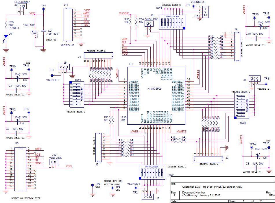
1 HI Sensor Array with Ground/Open or Supply/Open Sensors and SPI interface. Evaluation Board Madero, Mission Viejo, CA USA. Tel: Fax: sales@holtic.com Web: User Guide Feb 5,

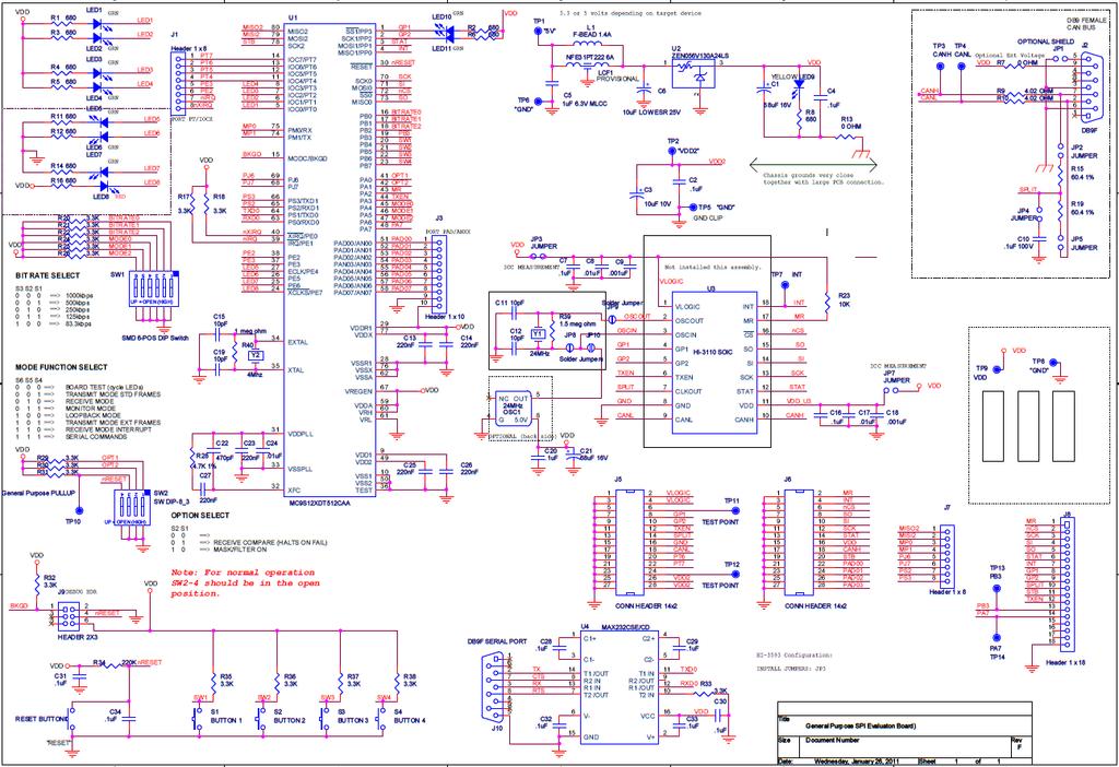
 plugs into a Holt General Purpose SPI Evaluation Board, based on a Freescale MC9S12XDT512")


2 INTRODUCTION The Holt HI 8435 Evaluation Board demonstrates the features of the HI Sensor IC. The board and the HI 8435 run from a single 3.3V+/ 5% supply voltage. The sensor input thresholds are programmable from 2V to 26V. The EVM (Evaluation Module) plugs into a Holt General Purpose SPI Evaluation Board, based on a Freescale MC9S12XDT512 microcontroller motherboard. The mother board MCU uses an SPI interface to communicate with the HI Switches and LEDs help navigate the operating modes and confirm data and status information. A Serial UART output from the MCU provides debug and data messages to be sent to a PC using any terminal emulation program such as HyperTerminal. The HI 8435 Evaluation Board plugs into to the Holt General Purpose SPI board through a 26 pin connector, as shown in the diagram below: This guide summarizes how to get set up and running quickly. Additional support material is provided on CD ROM. AN 8435, Rev. New HOLT INTEGRATED CIRCUITS 2 2/5/13
. CD with HI 8435 Users Guide.")
3 KIT CONTENTS This User Guide. General Purpose SPI Evaluation board. HI 8435 Evaluation Board (daughter card). CD with HI 8435 Users Guide. RS Pin Serial Cable. Demonstration Set up 3
4 Default Jumper and Switch Settings HI 8435 Board JUMPER POSITION DESCRIPTION J8 ON GND Link for HI 8435 supply J9 ON VDD Link for LED supply current (disconnect to measure HI 8435 supply current at TP13 J5 3 Bank 0 = Left Supply/Open, Right = GND/Open J6 3 Bank 1 = Left Supply/Open, Right = GND/Open J7 3 Bank 2 = Right Supply/Open, Left = GND/Open J10 3 Bank 3 = Right Supply/Open, Left = GND/Open J9 ON VDD Link FOR HI 8435 and LED supply current (disconnect and use ammeter to measure HI 8435 supply current, after removing LED jumper) SW1 POSITION DESCRIPTION 1 8 All ON Sensor input for Bank0, Sensors 0 7 SW2 POSITION DESCRIPTION 1 8 All ON Sensor input for Bank1, Sensors 8 15 SW3 POSITION DESCRIPTION 1 8 All ON Sensor input for Bank2, Sensors SW4 POSITION DESCRIPTION 1 8 All ON Sensor input for Bank3, Sensors
5 SPI Board JP POSITION DESCRIPTION 1 Open 2 Open 3 ON 4 Open 5 Open 6 Open 7 Open SW1 POSITION DESCRIPTION 1 ON BITR0 2 ON BITR1 3 ON BITR2 4 Open Mode0 5 Open Mode1 6 Open Mode2 SW2 POSITION DESCRIPTION 1 ON Opt1 2 ON Opt2 3 ON 4 Open Master Reset 5
 and J8 (GND LINK) connect VDD and GND to the HI 8435 and can be used to measure the device supply current.")
 is in the open position, otherwise the MCU will be held in the reset state.")

6 Initial Board Set up 1. Make sure the daughter board jumpers and switch positions are in the positions shown in the picture below. J12 (VDD LINK) and J8 (GND LINK) connect VDD and GND to the HI 8435 and can be used to measure the device supply current. The LED Jumper disconnects the LED so an accurate current measurement can be made. 2. For normal operation, ensure SW2 position 4 (MRST) is in the open position, otherwise the MCU will be held in the reset state. This MRST DIP switch allows easy interface of an external MCU to the HI Closing SW2 position 4 keeps the RESET pin low, forcing the Freescale MCU GPIOs into a high impedance state. For normal operation, keep this switch open and use the RESET button to reset the MCU during testing. AN 8435, Rev. New HOLT INTEGRATED CIRCUITS 6 2/5/13
7 3. Connect a +3.3V power supply to TP1 (RED) and ground to TP6 (BLK) of the Motherboard. This also supplies the HI 8435 daughter board with the same voltage. This is the only power supply needed by this demo. 4. After a power on reset, the program switches all LEDS on for 3 seconds; the software revision is then displayed on the LEDs for two seconds in binary format, where LED1 is the LSB. After two seconds, the LEDs are turned off. A text message is also sent to the Console Port. 5. All control of the HI 8435 is done through the Control Console. This requires use of a terminal emulator for communication, such as HyperTerminal or Tera Term. Windows versions earlier than Windows Vista Open HyperTerminal by clicking Start then All Programs; click the Windows Accessories then Communications program group. Double click HyperTerminal to run it. Windows versions Vista or later Then HyperTerminal is not available, use the Tera Term, supplied on the CD. Run teraterm 4.71.exe installer program from the Holt CD. Accept the license agreement stating redistribution is permitted provided that copyright notice is retained. The notice can be displayed from the Tera Term window by clicking Help then clicking About Tera Term. Continuing to install Accept the default install destination and click Next. At the Select Components screen, unselect all options except Additional Plugin = TTXResizeMenu and click Next. Select the installed language, then click Next. Accept the default Start Menu folder, then click Next. Select any desired shortcuts, then click Next. At the Ready to Install screen, click Install. Run the Tera Term program. At the New Connection screen, select (x)serial and choose the selected COM port, find the correct COM port using Device Manager. 6. Click Setup then Serial Port to open the serial port setup window. Choose these settings: Baud Rate: , Data: 8 bits, Parity: none, Stop: 1 bit, Flow Control: none If your PC has a serial port, using the DB 9 serial cable provided, connect the MCU board to the computer serial (COM) port. If your PC only has USB connectors then use a USB to serial converter (dongle) to connect (not provided). 7

8 7. The evaluation software is installed in the Motherboard microcontroller; this has been preloaded at the Holt Applications Support Center. On power up, the software displays a message on the monitor, as shown below. 8. Note: If under any circumstances, this software locks up, use the RESET key on the SPI board to recover. 9. Press key 1 to perform a Hardware Reset. Then press key 0 to read and display values of all read registers, it shows the default state as shown below: 8

9 10. DIP switches SW1 4 set a voltage level on the sensors inputs; there is one set of switches for each bank of sensors. The voltage source to the switches is selected using jumpers J4 7, with the jumper in the inner position the source is ground. When jumpers J4 7; are in position 3 the test point adjacent to the jumper is used to connect a sensor supply. 11. Initially it is easier to test the Supply/Open sense mode as no VWET current is required. To do this, ensure all switches and jumpers are in the default positions as shown at the beginning of this guide. With software displaying the Main Menu, screen press key 2. This brings up the Program Sense Menu as shown below: 9
10 Select Program All Sensors Supply/ Open by pressing key 1, then q to return to Main Menu. Press 0 again to read registers and verify that the Sense Bank Control reads 0x0F, see below. All 32 sensors are now set to detect the Supply/Open states. 10
11 12. Return to the main menu. The thresholds now need to be set. There are two ways to do this: 1: Preset software settings, key P. 2: Manual threshold selection, keys 4 and 5 If using the preset method, a screen like that shown below is displayed. Select the preset that fits your usage; for example key 1, Airbus. This sets the VTHL and VTHH thresholds as shown below: GND/Open VTLO is (7.5 6/2) = 4.5V VTHI is ( /2) = 10.5V Supply/Open VTLO is (9 6/2) = 6V VTHI is (9 + 6/2) = 12V 11

 then threshold (0F), press Q, then 5 and set Supply/Open")
12 13. If preferred, use the second option; manually setting thresholds and hysteresis, using keys 4 and 5. See screen below: Enter the hysteresis value as two hex digits, (06) then threshold (0F), press Q, then 5 and set Supply/Open thresholds, 06,

13 14. Press q to return to the main menu. Do a register read again to verify that register values were set correctly, see screen below: 15. If you used the example values, a threshold of 9V is set with a hysteresis of 6V for the Supply/Open mode, this results in VTHL = 6V and VTHH = 12V. This can be tested by connecting a voltage source to the test point on VSENSE0. Make sure all DIP switches are in the default position. Return to the main menu then select the monitor mode by pressing button m. This displays a screen that continually monitors the sensor banks. A screen like the one below will appear. 13

14 16. The screen above is monitoring the four register banks. 0xFF means all 8 sensor bits are at a 1 state. In Supply/Open, this means Opens are detected. Now connect a 0V source to the VSENSE0 test point. Increase the voltage up to +12V. Approaching 12V, Bank0 should start reading 0x00, indicating a closed switch has been detected, as shown in the screen below. 14
15 17. Now slowly reduce the voltage. Approaching 6V, Bank 0 should start reading 0xFF again. This verifies the threshold levels. 18. Return to the main menu by pressing any key. The GND/Open mode will be evaluated next. Press key 2 and then key 0. Then press q to return to Main Menu. Press 0 again to read registers and check that the Sense Bank Control Reg reads 0x00, see below. All 32 sensors are now set to detect the GND/Open states. 19. If threshold are using the example values, threshold = 0F and hysteresis = 06 gives a center threshold of 7.5V and a hysteresis of 6V, corresponding to a VTHL = 4.5V and VTHH = 10.5V. 20. A sensor bank or an individual sensor can also be monitored using the 9 key. For example press key 9, then key 0, to select Bank 0. You then have a choice of selecting all sensors from that Bank, or selecting just one. Press key 1. The selected the sensor outputs are shown on LEDs 1 8, corresponding to sensors 0 7 of that bank 15

16 21. To test sensor 1, bank 0 connect a voltage source to test point VSENSE0, all SW1 switches should be in the OFF position, except switch 2 should be ON. With 0V, LED2 should be lit. Ramp up the voltage on VSENSE; at around 10.5V the LED should go off, indicating the sensor has detected an OPEN. Slowly reduce voltage at around 4.5V the LED should come back on, indicating the sensor has detected a CLOSED. 22. In this monitor mode, the sensor state can also be monitored on pin PA7 of the SPI mother board, when the sensor changes state so does the level on PA7. This output can be used to trigger an oscilloscope or a data logger to capture the threshold trigger point. 16
17 Connecting external sensors To connect an external sensor, first make sure the corresponding DIP switch on switches SW1 4 is in the OPEN state. The sensor wires can be connected to the board on the pin headers J1 to J4, see table below. When using GND/Open sensors, the VWET terminal must be used to pull up the sensors to the higher VWET voltage. With VWET at 28V and VLOGIC at 3.3V, the wetting current will be approximately 0.88mA. If additional wetting current is required, connect an external resistor from VWET to the sense line. There are four VWET terminals, one for each bank of sensors, so the voltage should be applied to the corresponding VWET terminal on the board for that bank. See datasheet for more guidance on wetting current tables and adjustment. Pin Number Sensor Number J1 J2 J3 J GND GND GND GND Connection pins for external sensors Stand Alone Operation The evaluation board can be used in a standalone mode (without the lower MCU board). It requires the customer to have access to a SPI interface. Power should be connected between the VDD terminal and ground. The SPI controller should then be connected to J11, using the following pin connections: 17
18 Pin Number Label Description 1 VDD VDD, 3.3V Supply 2 nmr Master Reset 3 ncs Chip Select 4 SI Serial Input to HI SCK Serial Clock Input (up to 20MHz) 6 SO Serial Output from HI Not Used 8 Not Used 9 Not Used 10 Supply Ground (0V) GND J11 connection pins, for external SPI Other Modes An internal test mode is present on the HI This can be selected up by hitting key t from the main menu. Hit key 3. Another screen will appear allowing the HI 8435 to internally set the sensor inputs. This test mode can set the internal sensors input to: a) All Inputs Set Low (GND) b) All Inputs Set High (VDD) c) Odd Inputs Set Low (GND) d) Odd Inputs Set High (VDD) After setting the inputs and the sensors bits, use the key 0 command to read back the sensor data to verify correct operation. To exit test mode, a Hardware or Software reset should be used. Note that before using the test mode the minimum thresholds should be set, otherwise false failures could occur. 18
19 Self Test The self test feature (key S in the menu) runs through the internal test modes; testing the only the digital section of the device. If a register fails this will be reported or if a sensor fails, the Bank and pattern that failed will be shown on the screen. Soft Reset This resets all registers to the default state. 19
20 Appendix Lightning Protection All sense inputs are protected to RTCA/DO 160G, Section 22, Categories AZ and BZ, Waveforms 3, 4, 5A, with no external components. In addition, all inputs are also protected to ZZ, Waveforms 3 and 5B, to provide more robustness in composite airframe applications. For details of the Z levels please see the latest datasheet. The level of lightning protection can be increased by adding a resistor in series with the sensor input. On the Evaluation Board these resistors, R1 32, are populated with 0 ohm links, the value of R1 to R32 can be changed, refer to Application Note AN 305, available from the Holt website. The layout of a HI 8435 board should always have low conductivity paths from the device power/ground pin to the relevant power or ground origin. These paths should avoid proximity to sense or other signal traces; this applies to above and below as well as horizontally. It is good practice to have a power and ground moat beneath the sense line to prevent disturbance on these lines during a lightning event. REVISION HISTORY Revision Date Description of Change AN-8435, Rev. New New 20
21 21
22 22
User Guide March 2, 2015
 HI 8435 32 Sensor Array with Ground/Open or Supply/Open Sensors and SPI interface. Evaluation Board 23351 Madero, Mission Viejo, CA 92691. USA. Tel: + 1 949 859 8800 Fax: + 1 949 859 9643 Email: sales@holtic.com
USB-COMi-TB USB to Industrial Single RS-422 / 485 Adapter Manual. Specifications and Features
 USB-COMi-TB USB to Industrial Single RS-422 / 485 Adapter Manual The USB-COMi-TB USB-to-Industrial Single RS-422/485 Adapter is designed to make industrial communication port expansion quick and simple.
This 4-port RS-422/485 Adapter is provided with an external switching power adapter in the package.
 USB-4COMi-M USB to Quad RS-422/485 to Serial Adapter Manual The USB to Industrial Quad RS-422/485 Adapter is designed to make industrial communication port expansion quick and simple. Connecting to a USB
USB-16COMi-M 16-Port RS-422/485 USB Serial Adapter User Manual. Features and Specifications. Power Supply
 USB-16COMi-M 16-Port RS-422/485 USB Serial Adapter User Manual The USB to industrial 16-Port RS-422/485 Adapter is designed to make serial port expansion quick and simple. Connecting to a USB port on your
AN-619 APPLICATION NOTE
 APPLICATION NOTE One Technology Way P.O. Box 9106 Norwood, MA 02062-9106 Tel : 781/329-4700 Fax: 781/326-8703 www.analog.com Using the ADN8810 Demo Board v2.0 by Troy Murphy and Chris Kung OVERVIEW The
AN HI-3200 Avionics Data Management Engine Evaluation Board Software Guide
 August 12, 2011 AN - 166 HI-3200 Avionics Data Management Engine Evaluation Board Software Guide Introduction This application note provides more detail on the HI-3200 demo software provided in the Holt
S32K148 EVB QUICK START GUIDE REV1 APPLIES FOR: S32K148 EVB (SCH REV A/B) EXTERNAL USE
 EXTERNAL USE") S32K148 EVB QUICK START GUIDE REV1 APPLIES FOR: S32K148 EVB (SCH-29644 REV A/B) Contents: Get to Know S32K148 EVB Out of the Box Setup Introduction to OpenSDA S32DS IDE basics: Download Create a project
S32K148 EVB QUICK START GUIDE REV1 APPLIES FOR: S32K148 EVB (SCH-29644 REV A/B) Contents: Get to Know S32K148 EVB Out of the Box Setup Introduction to OpenSDA S32DS IDE basics: Download Create a project
Chipset Evaluation and Development Loadboard Version 2
 IA MSC-UGLB2 Chipset Evaluation and Development Loadboard Version 2 User Guide Revision 1.0r IA MSC-UGLB2 rev 1.0r 0907 2007, Silicon Laboratories, Inc. Silicon Labs, Inc. 400 West Cesar Chavez Austin,
USB-to-I2C. Professional Hardware User s Manual.
 USB-to-I2C Professional Hardware User s Manual https://www.i2ctools.com/ Information provided in this document is solely for use with the USB-to-I2C Professional product from SB Solutions, Inc. SB Solutions,
KNJN I2C bus development boards
 KNJN I2C bus development boards 2005, 2006, 2007, 2008 fpga4fun.com & KNJN LLC http://www.knjn.com/ Document last revision on January 1, 2008 R12 KNJN I2C bus development boards Page 1 Table of Contents
Evaluation Kit & Driver User s Guide
 15 Cabot Road Woburn, MA 01801 Tel: 781-935-1200 Fax: 781-935-2040 info@agiltron.com www.agiltron.com 1. Introduction This document describes the operation of the Evaluation Kit and Driver Ver. SW-DR-1
CoLinkEx_LPC11C14 EVB Kit User Guide
 CoLinkEx_LPC11C14 EVB Kit User Guide Rev. 1.0 Release: 2012-05-07 Website: http://www.coocox.org Forum: http://www.coocox.org/forum/forum.php?id=1 Techinal: master@coocox.com Market: market@coocox.com
HI Channel Ground/Open or Supply/Open Sensor with SPI Interface GENERAL DESCRIPTION FEATURES PIN CONFIGURATION APPLICATION
 June 2017 GENERAL DESCRIPTION 8-Channel Ground/Open or Supply/Open Sensor with SPI Interface FEATURES The is an 8-channel discrete-to-digital sensor fabricated with Silicon-on-Insulator (SOI) technology
Introduction & Specifications of Hi-Speed USB to Industrial Dual Ports RS-422/485 Adapter
 Introduction & Specifications of Hi-Speed USB to Industrial Dual Ports RS-422/485 Adapter USB to Dual RS-422/485 Adapter (USB-2COMi-M) USB to Dual Opto-isolated RS-422/485 Adapter (USB-2COMi-SI-M) - with
NITGEN FIM50 Series. Datasheet FIM50N. Version Stand-Alone Fingerprint Identification Device with Built-in CPU. Standalone with built-in CPU
 NITGEN FIM50 Series Stand-Alone Fingerprint Identification Device with Built-in CPU Datasheet Version 1.00 NITGEN Page: 1 Copyright 2010 NITGEN Co., Ltd. ALL RIGHTS RESERVED Serial Number: Specifications
Doc.Nr SCP1000 DEMO KIT User Manual
 Doc.Nr. 8268000.03 TABLE OF CONTENTS 1 Introduction...3 2 Quick start for using the...3 3 Hardware...4 4 GUI software...5 4.1 GUI software displays...7 4.1.1 USB serial port selection...7 4.1.2 Start up
Prototyping Module Datasheet
 Prototyping Module Datasheet Part Numbers: MPROTO100 rev 002 Zenseio LLC Updated: September 2016 Table of Contents Table of Contents Functional description PROTOTYPING MODULE OVERVIEW FEATURES BLOCK DIAGRAM
WICE-SPI Hardware Operation Manual
 WICE-SPI Hardware Operation Manual 1. Hardware Instruction 1. WICE-SPI processes data transmission, programming or emulation through USB 2.0 interface and does not need external power. 2. WICE-SPI is equipped
KNJN I2C bus development boards
 KNJN I2C bus development boards 2005, 2006, 2007, 2008 KNJN LLC http://www.knjn.com/ Document last revision on December 5, 2008 R22 KNJN I2C bus development boards Page 1 Table of Contents 1 The I2C bus...4
NITGEN FIM40 Series. Datasheet FIM40N. Version Stand-Alone Fingerprint Identification Device with Built-in CPU. Standalone with built-in CPU
 NITGEN FIM40 Series Stand-Alone Fingerprint Identification Device with Built-in CPU Datasheet Version 1.01 NITGEN Page: 1 Copyright 2011 NITGEN Co., Ltd. ALL RIGHTS RESERVED Serial Number: Specifications
Chapter 2 ICB Architecture Chapter 3 Board Components GPIO Interface RS-232 Interface RS-485 Interface...
 1 CONTENTS Chapter 1 Introduction... 3 1.1 Features...3 1.2 About the Kit...4 1.3 Getting Help...5 Chapter 2 ICB Architecture... 6 2.1 Layout and Components...6 2.2 Block Diagram of the ICB...7 Chapter
QUICK START GUIDE FOR DEMONSTRATION CIRCUIT 740 TRACKER/SEQUENCER DEMO BOARD
 DESCRIPTION QUICK START GUIDE FOR DEMONSTRATION CIRCUIT 740 LTC2922 Demonstration circuit 740 is a tracker/sequencer demo board featuring the LTC2922 that monitors up to five external power supplies and
User's Manual Rev. 1. Freescale Semiconductor Inc. TWRS08UNIVUM
 TWR-S08UNIV User's Manual Rev. 1 Freescale Semiconductor Inc. TWRS08UNIVUM Table of Contents 1. TWR-S08UNIV and TWR-S08DC Overview... 4 1.1 Contents... 5 1.2 Features... 5 2. Getting Started... 7 2.1 Reference
PI Scanner User Guide
 PI Scanner User Guide Table of Contents 1. Highlights 2. Overview 3. Installation 3.1. PI Scanner Software Installation 3.2. USB to Serial Interface Board Installation 3.3. Programming the PI Scanner IP
Basics of UART Communication
 Basics of UART Communication From: Circuit Basics UART stands for Universal Asynchronous Receiver/Transmitter. It s not a communication protocol like SPI and I2C, but a physical circuit in a microcontroller,
VLSI AppNote: VSx053 Simple DSP Board
 : VSx053 Simple DSP Board Description This document describes the VS1053 / VS8053 Simple DPS Board and the VSx053 Simple DSP Host Board. Schematics, layouts and pinouts of both cards are included. The
SAKURA-W. Side-channel AttacK User Reference Architecture SAKURA-W Quick Start Guide. [Version 0.9] October 19, 2014.
![SAKURA-W. Side-channel AttacK User Reference Architecture SAKURA-W Quick Start Guide. [Version 0.9] October 19, 2014.](/thumbs/77/76644229.jpg "SAKURA-W. Side-channel AttacK User Reference Architecture SAKURA-W Quick Start Guide. [Version 0.9] October 19, 2014.") Side-channel AttacK User Reference Architecture SAKURA-W Quick Start Guide [Version 0.9] SAKURA-W October 19, 2014 Satoh Laboratory, The University of Electro Communications Revision Record Date Version
Side-channel AttacK User Reference Architecture SAKURA-W Quick Start Guide [Version 0.9] SAKURA-W October 19, 2014 Satoh Laboratory, The University of Electro Communications Revision Record Date Version
PSIM Tutorial. How to Use SCI for Real-Time Monitoring in F2833x Target. February Powersim Inc.
 PSIM Tutorial How to Use SCI for Real-Time Monitoring in F2833x Target February 2013-1 - With the SimCoder Module and the F2833x Hardware Target, PSIM can generate ready-to-run codes for DSP boards that
BV4615. Dual Interface Zero Keypad. Product specification. Dec 2009 V0.a. ByVac Page 1 of 11
 Product specification Dec 2009 V0.a ByVac Page 1 of 11 Contents 1. Introduction...3 2. Features...3 3. Physical Specification...3 3.1. Serial connector...3 3.2. Multiple Devices...4 3.3. I2C...4 4. Output
MCP2120/MCP2150 DEVELOPER S KIT USER S GUIDE
 MCP2120/MCP2150 DEVELOPER S KIT USER S GUIDE Information contained in this publication regarding device applications and the like is intended by way of suggestion only. No representation or warranty is
Arduino Uno. Arduino Uno R3 Front. Arduino Uno R2 Front
 Arduino Uno Arduino Uno R3 Front Arduino Uno R2 Front Arduino Uno SMD Arduino Uno R3 Back Arduino Uno Front Arduino Uno Back Overview The Arduino Uno is a microcontroller board based on the ATmega328 (datasheet).
AVR Standalone ISP Programmer V2 Instructions
 1 of 11 AVR Standalone ISP Programmer V2 Instructions The AVR Standalone ISP Programmer is designed to accept a hex file from any terminal program *** and store it in external eeprom for later use. Once
For more detailed information about this product please refer to the QT510 datasheet.
 E510 1 User Manual 2 E510 User Manual OVERVIEW This kit is designed for evaluation and development of QT510-based QWheel Rotary slider. It includes a fully assembled rotary slider evaluation board, user
Symphony SoundBite Reference Manual
 Symphony SoundBite Reference Manual Document Number: SNDBITERM Rev. 2.0 09/2008 Contents Section 1, Introduction page 2 Section 2, Functional Blocks page 3 Section 3, Configuration and Connections page
TABLE 1: PACKAGE LIST. XRA1402IL16-F 16-pin QFN U7. XRA1402IG16-F 16-pin TSSOP U6. XRA1404IL16-F 16-pin QFN U7. XRA1404IG16-F 16-pin TSSOP U6
 REV. 1.0.0 INTRODUCTION XRA1402/1404 EVALUATION BOARD USER S MANUAL This user s manual is for the XRA1402/1404 8-bit evaluation board. Table 1 shows the different devices and packages that the evaluation
SCA8X0-21X Demo Kit User Manual. Doc.Nr C
 SCA8X0-21X0-3100 Demo Kit TABLE OF CONTENTS SCA8X0-21X0-31X0 DEMO KIT 1 Introduction...3 2 Quick start for using the SCA8X0-21X0-31X0 DEMO KIT...3 3 Hardware...4 4 GUI software...4 4.1 Resetting GUI and
User s Guide IoT Microcontroller Development Kit
 User s Guide IoT Microcontroller Development Kit 1.0 Introduction 2 1.1 Features 2 1.2 Board Pictures 3 2.0 Hardware 4 2.1 Bill of Materials 4 2.2 Pin Map Diagram 5 2.3 Block Diagram 6 2.4 Board Revisions
Installation Guide of Hi-Speed USB to Industrial Single RS-422/485 Adapter
 Installation Guide of Hi-Speed USB to Industrial Single RS-422/485 Adapter Introduction of USB-COMi and USB-COMi-SI The USB-COMi and USB-COMi-SI Industrial Single RS-422/485 Adapters are designed to make
Modtronix Engineering Modular Electronic Solutions SBC28DC. Single board computer for 28 pin DIP PICs
 Modtronix Engineering Modular Electronic Solutions Single board computer for 28 pin DIP PICs Table of Contents 1 Introduction...2 2 Features...4 3 Expansion Connectors...5 3.1 Daughter Board Connectors...5
17 Hatidhar st. Ra anana 43665, Israel Fax: Tel: UDEC-1. Universal Debug Center User Manual & Quick Start
 17 Hatidhar st. Ra anana 43665, Israel Fax: 09-7417422 Tel: 09-7417411 www.adcom.co.il UDEC-1 Universal Debug Center User Manual & Quick Start UM-004708-1 - Revision A Version Issued By Issue Date Comments
EMERALD-MM-8P. 8-Channel Software Programmable Protocol. Serial Port PC/104 TM Module. User Manual V1.20
 EMERALD-MM-8P 8-Channel Software Programmable Protocol Serial Port PC/104 TM Module User Manual V1.20 Copyright 2005, 2008, 2011 DIAMOND SYSTEMS CORPORATION 555 Ellis Street Mountain View, CA 94043 Tel
Wiring Section 3-3. NQ-Series communication ports support various types of (serial) communication.
 communication.") 3-3 Wiring NQ-Series models have, besides one power connector, a number of communication ports. Please refer to Table 2.2: Common specifications for NQ-Series and Table 2.3: Specifications per NQ-Series
3-3 Wiring NQ-Series models have, besides one power connector, a number of communication ports. Please refer to Table 2.2: Common specifications for NQ-Series and Table 2.3: Specifications per NQ-Series
USB Debug Adapter. Power USB DEBUG ADAPTER. Silicon Laboratories. Stop. Run. Figure 1. Hardware Setup using a USB Debug Adapter
 C8051F2XX DEVELOPMENT KIT USER S GUIDE 1. Kit Contents The C8051F2xx Development Kits contain the following items: C8051F206 or C8051F226 Target Board C8051Fxxx Development Kit Quick-Start Guide Silicon
Galep-Adapter DIL-40 => ISP-ASYNC/SYNC Article-No.:
 1 of 10 -- English -- Adapter for MCU s, which are in system programmable. -- Deutsch -- Adapter für MCU s, die im System programmiert werden können. Illustration 1: ISP-ASYNC/SYNC-adapter 210915 Illustration
Embedded Navigation Solutions VN 100, VN 200 & VN 300 Development Board User Manual
 Embedded Navigation Solutions VN 100, VN 200 & VN 300 Development Board User Manual VectorNav Technologies Contact Info 10501 Markison Road Phone +1 512 772 3615 Dallas, Texas 75238 Email support@vectornav.com
Win-I2CUSB Hardware User s Manual
 Win-I2CUSB Hardware User s Manual http://www.demoboard.com Information provided in this document is solely for use with the Win-I2CUSB product from The Boardshop. The Boardshop and SB Solutions, Inc. reserve
BV4626 General Purpose I/O. Product specification. Mar 2010 V0.a. ByVac Page 1 of 13
 General Purpose I/O Product specification Mar 2010 V0.a ByVac Page 1 of 13 Contents 1. Introduction... 3 2. Features... 3 3. Physical Specification... 3 3.1. JP7... 3 3.2. Control Interface... 4 3.3. Serial
User Manual Rev. 0. Freescale Semiconductor Inc. FRDMKL02ZUM
 FRDM-KL02Z User Manual Rev. 0 Freescale Semiconductor Inc. FRDMKL02ZUM 1. Overview The Freescale Freedom development platform is an evaluation and development tool ideal for rapid prototyping of microcontroller-based
XNUCLEO-F030R8, Improved STM32 NUCLEO Board
 XNUCLEO-F030R8, Improved STM32 NUCLEO Board STM32 Development Board, Supports Arduino, Compatible with NUCLEO-F030R8 XNUCLEO-F030R8 Features Compatible with NUCLEO-F030R8, onboard Cortex-M0 microcontroller
P&E Microcomputer Systems, Inc. P.O. Box 2044, Woburn, MA 01888, USA
 P&E Microcomputer Systems, Inc. P.O. Box 2044, Woburn, MA 01888, USA TEL: (617) 353-9206 FAX: (617) 353-9205 http://www.pemicro.com USB-ML-MON08 Rev D Technical Summary Document # PE3357, Version 1.01
Atmel AVR datasheet. Matrix Multimedia Atmel AVR Board EB Contents
 Atmel AVR datasheet Contents 1. About this document 2. General information 3. Board overview 4. Getting Started 5. Block schematic and description Appendix A. Circuit diagram B. Compatible AVR device C.
Cytron USB to UART Converter UC00A
 Cytron USB to UART Converter UC00A User s Manual V1.1 August 2009 Information contained in this publication regarding device applications and the like is intended through suggestion only and may be superseded
MegaAVR-DEVelopment Board Progressive Resources LLC 4105 Vincennes Road Indianapolis, IN (317) (317) FAX
 (317) FAX") MegaAVR-DEVelopment Board Progressive Resources LLC 4105 Vincennes Road Indianapolis, IN 46268 (317) 471-1577 (317) 471-1580 FAX http://www.prllc.com GENERAL The MegaAVR-Development board is designed for
MegaAVR-DEVelopment Board Progressive Resources LLC 4105 Vincennes Road Indianapolis, IN 46268 (317) 471-1577 (317) 471-1580 FAX http://www.prllc.com GENERAL The MegaAVR-Development board is designed for
PCI Host Controller 14a Hardware Reference Release 1.2 (October 16, 2017)
") PCI Host Controller 14a Hardware Reference 1 PCI Host Controller 14a Hardware Reference Release 1.2 (October 16, 2017) Purpose: Host Controller to support the PCI bus according to the PCI/104 specification.
PCI Host Controller 14a Hardware Reference 1 PCI Host Controller 14a Hardware Reference Release 1.2 (October 16, 2017) Purpose: Host Controller to support the PCI bus according to the PCI/104 specification.
CEIBO FE-51RD2 Development System
 CEIBO FE-51RD2 Development System Development System for Atmel AT89C51RD2 Microcontrollers FEATURES Emulates Atmel AT89C51RD2 60K Code Memory Real-Time Emulation Frequency up to 40MHz / 3V, 5V ISP and
Case USB-MUX-4C2L 4 CAN - 2 LIN/ISO
 Case USB-MUX-4C2L 4 CAN - 2 LIN/ISO Installation guide Document n. 054114-04 Published 08/07/2005 ANNECY ELECTRONIQUE Z.A. Les Marais 74410 St JORIOZ Phone : +33 (0) 450 68 90 65 Fax: +33 (0) 450 68 58
Installation Guide of Hi-Speed USB to Octal RS-232/422/485 Adapter
 Installation Guide of Hi-Speed USB to Octal RS-232/422/485 Adapter Introduction The USB to Octal Serial Adapter is designed to make serial port expansion quick and simple. Connecting to a USB port on your
Chapter 1 Introduction Features Getting Help Chapter 2 ICB Architecture Layout and Components...
 1 CONTENTS Chapter 1 Introduction... 2 1.1 Features... 2 1.2 Getting Help... 3 Chapter 2 ICB Architecture... 4 2.1 Layout and Components... 4 2.2 Block Diagram of the ICB... 5 Chapter 3 Board Components...
EVB9S08DZ60. Demonstration Board for Freescale MC9S08DZ60. User s Manual
 EVB9S08DZ60 Demonstration Board for Freescale MC9S08DZ60 User s Manual EVB9S08DZ60 Evaluation Board for Freescale MC9S08DZ60 (64-Pin LQFP) User s Manual Revision 1.0 Copyright 2006 SofTec Microsystems
Key Specifications. Description. Applications. BC118-Disovery Board v1. Manual Rev B
 Key Specifications Bluetooth Certified 4.0 Audio module Single Mode: Bluetooth Low Energy (BLE) Embedded Bluetooth Protocol Stack Supports GATT Profile, Audio, Proximity, and ibeacon Supports I2C and UART
imcu7100evb User s Guide
 Version 1.0 2011 WIZnet Co., Inc. All Rights Reserved. For more information, visit our website at http://www.wiznet.co.kr Copyright 2011WIZnet Co., Inc. All rights reserved. Table of Contents 1 Overview...3
8 Port USB to RS- 232/422/485 Octal Adapter. Product Manual. Coolgear, Inc. Version 1.1 April 2018 Model Number: USB-8COMi-RM.
 8 Port USB to RS- 232/422/485 Octal Adapter Product Manual Coolgear, Inc. Version 1.1 April 2018 Model Number: USB-8COMi-RM 2 USB-8COMi-RM Product Manual Revision History Revision Date Author Comments
)8-,768'HY.LW 2YHUYLHZ. )XMLWVX0LNURHOHNWURQLN*PE+ Am Siebenstein Dreieich-Buchschlag, Germany
8-,768'HY.LW 2YHUYLHZ. )XMLWVX0LNURHOHNWURQLN*PE+ Am Siebenstein Dreieich-Buchschlag, Germany") )8-,768'HY.LW 2YHUYLHZ )XMLWVX0LNURHOHNWURQLN*PE+ Am Siebenstein 6-10 63303 Dreieich-Buchschlag, Germany Revision: V1.0 Date: 05.08.1999 Introduction to FUJITSU Development Kit for 16LX CPU family DevKit16
)8-,768'HY.LW 2YHUYLHZ )XMLWVX0LNURHOHNWURQLN*PE+ Am Siebenstein 6-10 63303 Dreieich-Buchschlag, Germany Revision: V1.0 Date: 05.08.1999 Introduction to FUJITSU Development Kit for 16LX CPU family DevKit16
ZFSM-201-KIT-1 Wireless UART Application User Guide
 Free Star Pro Series ZFSM-201-KIT-1 Wireless UART Application User Guide ZFSM-201-1 FreeStar Pro Module Document # 0006-00-08-06-000 (Rev A) Table of Contents 1 OVERVIEW... 2 1.1 DESCRIPTION... 2 2 COMMUNICATIONS
NITGEN FIM5360. Datasheet FIM5360. Version Supported Firmware Version: 1.11 or above
 NITGEN FIM5360 Stand-Alone Fingerprint Identification Device with Built-in CPU Datasheet Supported Firmware Version: 1.11 or above Version 1.04 NITGEN Page: 1 Copyright 2011 NITGEN Co., Ltd. ALL RIGHTS
Quick Start Guide. S12VR64EVB S12 MagniV Mixed-Signal MCUs. S12 MagniV
 S12VR64EVB S12 MagniV Mixed-Signal MCUs S12 MagniV Get to Know the S12VR64EVB LIN Connectors Potentiometer SW1 SW2 Analog Input Header External Power Supply Banana Connectors JM60 Integrated BDM Barrel
CMS-8GP32. A Motorola MC68HC908GP32 Microcontroller Board. xiom anufacturing
 CMS-8GP32 A Motorola MC68HC908GP32 Microcontroller Board xiom anufacturing 2000 717 Lingco Dr., Suite 209 Richardson, TX 75081 (972) 994-9676 FAX (972) 994-9170 email: Gary@axman.com web: http://www.axman.com
Tech Note 16 XDS220 I/O Interface
 Tech Note 16 XDS220 I/O Interface Document Revision 0.01 November 26, 2012 Page 1 of 10 1 INTRODUCTION This technical note is a guide to operate the XDS220 I/O interface. The I/O interface supports the
KSZ9692PB User Guide Brief
 KSZ9692PB User Guide Brief KSZ9692PB Evaluation Platform Rev 2.0 General Description The KSZ9692PB Evaluation Platform accelerates product time-to-market by providing a hardware platform for proof-of-concept,
Getting Started with InnoSwitch TM 3-Pro Code Library using Arduino
 Title Author Document Number Getting Started with InnoSwitch TM 3-Pro Code Library using Arduino Applications Engineering Department Application Note 77 (AN-77) Date September 6, 2018 Revision 1.0 Summary
USB to RS-232/RS422/485. US-101-I USB To Serial Operation Manual
 USB to RS-232/RS422/485 US-101-I USB To Serial Operation Manual First Edition, Jun 2008 Table of Contents 1. Introduction 2 2. Package checklist 3 3. Product Specification 4 4. Product Panel Views Description
This manual provides information for the final user application developer on how to use SPC57S-Discovery microcontroller evaluation board.
 User manual SPC570S-DISP: Discovery+ Evaluation Board Introduction This manual provides information for the final user application developer on how to use SPC57S-Discovery microcontroller evaluation board.
EASY219 / IEC CANopen Master / Slave
 General Description The EASY219 is an all round high performance DIP- Chip PLC based on the Infineon C164 controller. It covers the powerful PLC runtime system CoDeSys and a CANopen master or slave in
DEV16T. LCD Daughter board
 LCD Daughter board Table of Contents 1 Introduction...2 2 Features...3 3 Expansion Connectors...4 3.1 Daughter Board Connectors...4 4 LCD Display...5 5 Input Buttons S1 to S4...5 6 Buzzer...5 7 Connector
TMC428 Evaluation Kit V2.0 Manual English
 TMC428 Evaluation Kit V2.0 Manual English Version: 2.01 July 30 th, 2002 2 TMC428 Evaluation Kit V2.01 Version Version Date Author Remarks 2.00 2002-07-29 OK Created from version 1.02 2.01 2002-07-30 OK
ARDUINO UNO REV3 Code: A000066
 ARDUINO UNO REV3 Code: A000066 The UNO is the best board to get started with electronics and coding. If this is your first experience tinkering with the platform, the UNO is the most robust board you can
Wi125 Evaluation Kit User Manual
 Wi125 Evaluation Kit User Manual Issue: R01 Available at Digi-Key www.digikey.com Bulletin SG172-DKUM Revision R01 Date 06 May 2010 Table of Contents 1. Introduction 3 2. Wi125 Evaluation Board Overview
5. What happens if we attempt to program a new frequency outside the specified speed grade of the device?
 Si57x FAQ Rev. 0.2 Overview This document is intended to address common questions about the Silicon Laboratories programmable oscillator Si570 XO and Si571 VCXO products. The term Si57x stands for both
AVR Standalone ISP Chip Copier Instructions
 1 of 12 AVR Standalone ISP Chip Copier Instructions The AVR Standalone ISP Chip Copier will read the contents of any device in the device list below and store the data in memory to be used for programming
BNO080 Development Kit for Nucleo Quick Start Guide
 BNO080 Development Kit for Nucleo Quick Start Guide The BNO080 is a System in Package (SiP) that integrates a triaxial accelerometer, a triaxial gyroscope, magnetometer and a 32-bit ARM Cortex -M0+ microcontroller
Evaluation Board User Guide UG-035
 Evaluation Board User Guide UG-035 One Technology Way P.O. Box 9106 Norwood, MA 02062-9106, U.S.A. Tel: 781.329.4700 Fax: 781.461.3113 www.analog.com Evaluating the AD9552 Oscillator Frequency Upconverter
SERDESUB 913ROS DS90UB913Q Serializer and DS90UB914Q Deserializer Evaluation Kit User s Manual
 SERDESUB 913ROS DS90UB913Q Serializer and DS90UB914Q Deserializer Evaluation Kit User s Manual Rev 2.1 1 Texas Instruments 11/19/2012 Contents SERDESUB 913ROS... 1 DS90UB913Q Serializer and DS90UB914Q
Wireless Modem Evaluation Board User s Guide
 Features Supports all CCI Modems and Radios Two independent transceivers and interfaces RS-232 Host Serial and USB Serial Communications RS-232,TTL Digital Serial and USB Host Interfaces Wireless modem
CSCI 6907 PROJECT PROPOSAL LIGHTS OUT MANAGEMENT
 CSCI 6907 PROJECT PROPOSAL LIGHTS OUT MANAGEMENT JAMES LEE JAMESLEE@GWU.EDU. Project Abstract I am a system administrator who manages hundreds of Unix systems. One of the essential tools to ensure I don
Product Manual. 2 Port USB to RS-422 /485 Optical Isolated Adapter. Coolgear, Inc. Version 1.1 March 2018 Model Number: USB-2COMi-Si-M
 2 Port USB to RS-422 /485 Optical Isolated Adapter Product Manual Coolgear, Inc. Version 1.1 March 2018 Model Number: USB-2COMi-Si-M 2 USB-2COMi-Si-M Product Manual Revision History Revision Date Author
LAB #1: The CSM12C32 Module and PBMCUSLK Project Board
 CS/EE 5780/6780 Handout #1 Spring 2007 Myers LAB #1: The CSM12C32 Module and PBMCUSLK Project Board Lab writeup is due to your TA at the beginning of your next scheduled lab. Don t put this off to the
TEMIC 51T (Temic) EMULATION
 EMULATION") Note: To use with frequencies above 40Mhz it will be required to use an emulator board that has been specially modified to obtain high frequency operation and will work only with the POD-51Temic. The EPROM
Note: To use with frequencies above 40Mhz it will be required to use an emulator board that has been specially modified to obtain high frequency operation and will work only with the POD-51Temic. The EPROM
Getting started with your DGH module:
 Getting started with your DGH module: This document contains step-by-step instructions to quickly connect and communicate with your new DGH modules. For most applications, new modules require a one-time
Table 1. RS232 Serial Adapter DEBUG Connector Pin Descriptions
 RS232 SERIAL ADAPTER (EC2) USER S GUIDE 1. Contents The RS232 Serial Adapter (EC2) package contains the following items: RS232 Serial Adapter (RS232 to Debug Interface) 7 Ribbon Cable 2. RS232 Serial Adapter
ZIC2410 User Guide Device-Programmer Software Manual
 ZIC2410 Series ZIC2410 User Guide Device-Programmer Software Manual 0005-05-08-00-001 (Rev B) Table of Contents 1 INTRODUCTION & PURPOSE... 3 1.1 DEFINITIONS... 3 1.2 REFERENCED DOCUMENTS... 3 1.3 PREREQUISITES...
UM QN908x Quick Start. Document information. QN908x, Quick Start, Development Kit, QN9080 DK, QN9080 Development Kit
 QN908x Quick Start Rev.2.0 21 March 2018 User manual Document information Info Keywords Abstract Content QN908x, Quick Start, Development Kit, QN9080 DK, QN9080 Development Kit This Quick Start document
Installation Guide of Hi-Speed USB to Industrial I/O Adapter
 Installation Guide of Hi-Speed USB to Industrial I/O Adapter Introduction of USB-COMi-SI-M The USB Industrial I/O Adapter is designed to make industrial communication port expansion quick and simple. Connecting
CDN503 HIGH DENSITY I/O ADAPTER USER GUIDE
 CDN503 HIGH DENSITY I/O ADAPTER USER GUIDE 13050301 (c) Copyright DIP Inc., 1996 DIP Inc. P.O. Box 9550 MORENO VALLEY, CA 92303 714-924-1730 CONTENTS DN503 PRODUCT OVERVIEW 1 DN503 INSTALLATION 1 POWER
Blue Point Engineering
 Blue Point Engineering Board - Pro Module (E) Instruction Pointing the Way to Solutions! Controller I Version 2.1 The Board Pro E Module provides the following features: Up to 4 minutes recording time
EX KVIS RS232/422/485 3-in-1 Serial to USB Adapter (w/ 4KV Isolation, 15KV ESD Surge Protection)
") EX-1331-4KVIS RS232/422/485 3-in-1 Serial to USB Adapter (w/ 4KV Isolation, 15KV ESD Surge Protection) 1. Introduction Thank you for purchasing this RS232/422/485 3-in-1 Serial to USB Adapter. It is an
EX-1331-4KVIS RS232/422/485 3-in-1 Serial to USB Adapter (w/ 4KV Isolation, 15KV ESD Surge Protection) 1. Introduction Thank you for purchasing this RS232/422/485 3-in-1 Serial to USB Adapter. It is an
Nios Embedded Processor Development Board
 Nios Embedded Processor Development Board July 2003, ver. 2.2 Data Sheet Introduction Development Board Features Functional Overview This data sheet describes the features and functionality of the Nios
EB-51 Low-Cost Emulator
 EB-51 Low-Cost Emulator Development Tool for 80C51 Microcontrollers FEATURES Emulates 80C51 Microcontrollers and Derivatives Real-Time Operation up to 40 MHz 3.3V or 5V Voltage Operation Source-Level Debugger
Embedded Development Platform Getting Started Guide for Microchip PIM Carrier Module
 Embedded Development Platform Getting Started Guide for Microchip PIM Carrier Module EDP-CM-PIM Version 3.11 February 2011 Contents 1. Introduction 3 2. Prepare to run the Hello World Program 4 2.1 Software
IO64 User's Manual. Rev C. Document
 IO64 User's Manual Rev C Document 940524 (c) 1994 by Alcorn McBride Inc. 3300 S. Hiawassee Bldg. 105 Orlando, Florida 32835 Tel: (407) 296-5800 Fax: (407) 296-5801 Every effort has been made to assure
EX & EX-45362IS 2S RS232/422/485 3-in-1 Serial PCIe Card
 EX-45362 & EX-45362IS 2S RS232/422/485 3-in-1 Serial PCIe Card Congratulation on your purchasing this high performance 2-Port RS232/422/485 3-in-1 Serial PCIe Host Adapter. The adapter is high speed PCIe