User Guide March 2, 2015
|
|
|
- Edward Webster
- 5 years ago
- Views:
Transcription

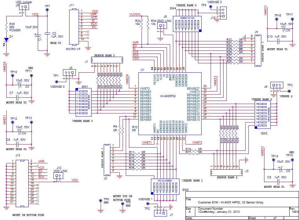
1 HI Sensor Array with Ground/Open or Supply/Open Sensors and SPI interface. Evaluation Board Madero, Mission Viejo, CA USA. Tel: Fax: sales@holtic.com Web: User Guide March 2,


2 INTRODUCTION The Holt HI 8435 Evaluation Board demonstrates the features of the HI Sensor IC. The board and the HI 8435 run from a single 3.3V+/ 5% supply voltage. The sensor input thresholds are programmable from 2V to 26V. The EVM (Evaluation Module) plugs into a Holt General Purpose SPI Evaluation Board, based on a 16 bit, Freescale MC9S12XDT512 microcontroller motherboard. The Holt CD, included with the evaluation kit, contains example source code, allowing the customer an easy path to developing their own control software. The mother board MCU uses an SPI interface to communicate with the HI Switches and LEDs help navigate the operating modes and confirm data and status information. A Serial UART output from the MCU provides debug and data messages to be sent to a PC using any terminal emulation program such as HyperTerminal. The HI 8435 Evaluation Board plugs into to the Holt General Purpose SPI board through a 26 pin connector, as shown in the diagram below: This guide summarizes how to get set up and running quickly. Additional support material is provided on CD ROM. 2
. CD with HI 8435 Users Guide and example source code.")
3 KIT CONTENTS This User Guide. General Purpose SPI Evaluation board. HI 8435 Evaluation Board (daughter card). CD with HI 8435 Users Guide and example source code. RS Pin Serial Cable. Demonstration Set up 3
4 Default Jumper and Switch Settings HI 8435 Board JUMPER POSITION DESCRIPTION J8 ON GND Link for HI 8435 supply J9 ON VDD Link for LED supply current (disconnect to measure HI 8435 supply current at TP13) J5 3 Bank 0 = Left Supply/Open, Right = GND/Open J6 3 Bank 1 = Left Supply/Open, Right = GND/Open J7 3 Bank 2 = Right Supply/Open, Left = GND/Open J10 3 Bank 3 = Right Supply/Open, Left = GND/Open J9 ON VDD Link FOR HI 8435 and LED supply current (disconnect and use ammeter to measure HI 8435 supply current, after removing LED jumper) SW1 POSITION DESCRIPTION 1 8 All ON Sensor input for Bank0, Sensors 0 7 SW2 POSITION DESCRIPTION 1 8 All ON Sensor input for Bank1, Sensors 8 15 SW3 POSITION DESCRIPTION 1 8 All ON Sensor input for Bank2, Sensors SW4 POSITION DESCRIPTION 1 8 All ON Sensor input for Bank3, Sensors
5 SPI Board JP POSITION DESCRIPTION 1 Open 2 Open 3 ON 4 Open 5 Open 6 Open 7 Open SW1 POSITION DESCRIPTION 1 ON BITR0 2 ON BITR1 3 ON BITR2 4 Open Mode0 5 Open Mode1 6 Open Mode2 SW2 POSITION DESCRIPTION 1 ON Opt1 2 ON Opt2 3 ON 4 Open Master Reset 5
 and J8 (GND LINK) connect VDD and GND to the HI 8435 and can be used to measure the device supply current.")
 is in the open position, otherwise the MCU will be held in the reset state.")

6 Initial Board Set up 1. Make sure the daughter board jumpers and switch positions are in the positions shown in the picture below. J12 (VDD LINK) and J8 (GND LINK) connect VDD and GND to the HI 8435 and can be used to measure the device supply current. The LED Jumper disconnects the LED so an accurate current measurement can be made. 2. For normal operation, ensure SW2 position 4 (MRST) is in the open position, otherwise the MCU will be held in the reset state. This MRST DIP switch allows easy interface of an external MCU to the HI Closing SW2 position 4 keeps the RESET pin low, forcing the Freescale MCU GPIOs into a high impedance state. For normal operation, keep this switch open and use the RESET button to reset the MCU during testing. AN 8435, Rev. B HOLT INTEGRATED CIRCUITS 6 3/2/15
7 3. Connect a +3.3V power supply to TP1 (RED) and ground to TP6 (BLK) of the Motherboard. This also supplies the HI 8435 daughter board with the same voltage. This is the only power supply needed by this demo. 4. After a power on reset, the program switches all LEDS on for 3 seconds; the software revision is then displayed on the LEDs for two seconds in binary format, where LED1 is the LSB. After two seconds, the LEDs are turned off. A text message is also sent to the Console Port. 5. All control of the HI 8435 is done through the Control Console. This requires use of a terminal emulator for communication, such as HyperTerminal or Tera Term. Windows versions earlier than Windows Vista Open HyperTerminal by clicking Start then All Programs; click the Windows Accessories then Communications program group. Double click HyperTerminal to run it. Windows versions Vista or later Then HyperTerminal is not available, use the Tera Term, supplied on the CD. Run teraterm 4.71.exe installer program from the Holt CD. Accept the license agreement stating redistribution is permitted provided that copyright notice is retained. The notice can be displayed from the Tera Term window by clicking Help then clicking About Tera Term. Continuing to install Accept the default install destination and click Next. At the Select Components screen, unselect all options except Additional Plugin = TTXResizeMenu and click Next. Select the installed language, then click Next. Accept the default Start Menu folder, then click Next. Select any desired shortcuts, then click Next. At the Ready to Install screen, click Install. Run the Tera Term program. At the New Connection screen, select (x)serial and choose the selected COM port, find the correct COM port using Device Manager. 6. Click Setup then Serial Port to open the serial port setup window. Choose these settings: Baud Rate: , Data: 8 bits, Parity: none, Stop: 1 bit, Flow Control: none If your PC has a serial port, using the DB 9 serial cable provided, connect the MCU board to the computer serial (COM) port. If your PC only has USB connectors then use a USB to serial converter (dongle) to connect (not provided). 7

8 7. The evaluation software is installed in the Motherboard microcontroller; this has been preloaded at the Holt Applications Support Center. On power up, the software displays a message on the monitor, as shown below. 8. Note: If under any circumstances, this software locks up, use the RESET key on the SPI board to recover. 9. Press key 1 to perform a Hardware Reset. Then press key 0 to read and display values of all read registers, it shows the default state as shown below: 8
9 10. DIP switches SW1 4 set a voltage level on the sensors inputs; there is one set of switches for each bank of sensors. The voltage source to the switches is selected using jumpers J4 7, with the jumper in the inner position the source is ground. When jumpers J4 7; are in position 3 the test point adjacent to the jumper is used to connect a sensor supply. 11. Initially it is easier to test the Supply/Open sense mode as no VWET current is required. To do this, ensure all switches and jumpers are in the default positions as shown at the beginning of this guide. With software displaying the Main Menu, screen press key 2. This brings up the Program Sense Menu as shown below: 9

10 Select Program All Sensors Supply/ Open by pressing key 1, then q to return to Main Menu. Press 0 again to read registers and verify that the Sense Bank Control reads 0x0F, see below. All 32 sensors are now set to detect the Supply/Open states. 10

11 12. Return to the main menu. The thresholds now need to be set. There are two ways to do this: 1: Preset software settings, key P. 2: Manual threshold selection, keys 4 and 5 If using the preset method, a screen like that shown below is displayed. Select the preset that fits your usage; for example key 1, Airbus. This sets the VTHL and VTHH thresholds as shown below: GND/Open VTLO is (7.5 6/2) = 4.5V VTHI is ( /2) = 10.5V Supply/Open VTLO is (9 6/2) = 6V VTHI is (9 + 6/2) = 12V 11

 then threshold (0F), press Q, then 5 and set Supply/Open")
12 13. If preferred, use the second option; manually setting thresholds and hysteresis, using keys 4 and 5. See screen below: Enter the hysteresis value as two hex digits, (06) then threshold (0F), press Q, then 5 and set Supply/Open thresholds, 06,
13 14. Press q to return to the main menu. Do a register read again to verify that register values were set correctly, see screen below: 15. If you used the example values, a threshold of 9V is set with a hysteresis of 6V for the Supply/Open mode, this results in VTHL = 6V and VTHH = 12V. This can be tested by connecting a voltage source to the test point on VSENSE0. Make sure all DIP switches are in the default position. Return to the main menu then select the monitor mode by pressing button m. This displays a screen that continually monitors the sensor banks. A screen like the one below will appear. 13

14 16. The screen above is monitoring the four register banks. 0xFF means all 8 sensor bits are at a 1 state. In Supply/Open, this means Opens are detected. Now connect a 0V source to the VSENSE0 test point. Increase the voltage up to +12V. Approaching 12V, Bank0 should start reading 0x00, indicating a closed switch has been detected, as shown in the screen below. 14

15 17. Now slowly reduce the voltage. Approaching 6V, Bank 0 should start reading 0xFF again. This verifies the threshold levels. 18. Return to the main menu by pressing any key. The GND/Open mode will be evaluated next. Press key 2 and then key 0. Then press q to return to Main Menu. Press 0 again to read registers and check that the Sense Bank Control Reg reads 0x00, see below. All 32 sensors are now set to detect the GND/Open states. 19. If threshold are using the example values, threshold = 0F and hysteresis = 06 gives a center threshold of 7.5V and a hysteresis of 6V, corresponding to a VTHL = 4.5V and VTHH = 10.5V. 20. A sensor bank or an individual sensor can also be monitored using the 9 key. For example press key 9, then key 0, to select Bank 0. You then have a choice of selecting all sensors from that Bank, or selecting just one. Press key 1. The selected the sensor outputs are shown on LEDs 1 8, corresponding to sensors 0 7 of that bank 15

16 21. To test sensor 1, bank 0 connect a voltage source to test point VSENSE0, all SW1 switches should be in the OFF position, except switch 2 should be ON. With 0V, LED2 should be lit. Ramp up the voltage on VSENSE; at around 10.5V the LED should go off, indicating the sensor has detected an OPEN. Slowly reduce voltage at around 4.5V the LED should come back on, indicating the sensor has detected a CLOSED. 22. In this monitor mode, the sensor state can also be monitored on pin PA7 of the SPI mother board, when the sensor changes state so does the level on PA7. This output can be used to trigger an oscilloscope or a data logger to capture the threshold trigger point. 16
17 Connecting external sensors To connect an external sensor, first make sure the corresponding DIP switch on switches SW1 4 is in the OPEN state. The sensor wires can be connected to the board on the pin headers J1 to J4, see table below. When using GND/Open sensors, the VWET terminal must be used to pull up the sensors to the higher VWET voltage. With VWET at 28V and VLOGIC at 3.3V, the wetting current will be approximately 0.88mA. If additional wetting current is required, connect an external resistor from VWET to the sense line. There are four VWET terminals, one for each bank of sensors, so the voltage should be applied to the corresponding VWET terminal on the board for that bank. See datasheet for more guidance on wetting current tables and adjustment. Pin Number Sensor Number J1 J2 J3 J GND GND GND GND Connection pins for external sensors Stand Alone Operation The evaluation board can be used in a standalone mode (without the lower MCU board). It requires the customer to have access to a SPI interface. Power should be connected between the VDD terminal and ground. The SPI controller should then be connected to J11, using the following pin connections: 17
18 Pin Number Label Description 1 VDD VDD, 3.3V Supply 2 nmr Master Reset 3 CSn Chip Select 4 SI Serial Input to HI SCK Serial Clock Input (up to 20MHz) 6 SO Serial Output from HI Not Used 8 Not Used 9 Not Used 10 Supply Ground (0V) GND J11 connection pins, for external SPI Other Modes An internal test mode is present on the HI This can be selected up by hitting key t from the main menu. Hit key 3. Another screen will appear allowing the HI 8435 to internally set the sensor inputs. This test mode can set the internal sensors input to: a) All Inputs Set Low (GND) b) All Inputs Set High (VDD) c) Odd Inputs Set Low (GND) d) Odd Inputs Set High (VDD) After setting the inputs and the sensors bits, use the key 0 command to read back the sensor data to verify correct operation. To exit test mode, a Hardware or Software reset should be used. Note that before using the test mode the minimum thresholds should be set, otherwise false failures could occur. 18
19 Self Test The self test feature (key S in the menu) runs through the internal test modes; testing the only the digital section of the device. If a register fails this will be reported or if a sensor fails, the Bank and pattern that failed will be shown on the screen. Soft Reset This resets all registers to the default state. 19
20 20

21 21
22 Appendix 1 Lightning Protection All sense inputs are protected to RTCA/DO 160G, Section 22, Categories AZ and BZ, Waveforms 3, 4, 5A, with no external components. In addition, all inputs are also protected to ZZ, Waveforms 3 and 5B, to provide more robustness in composite airframe applications. For details of the Z levels please see the latest datasheet. The level of lightning protection can be increased by adding a resistor in series with the sensor input. On the Evaluation Board these resistors, R1 32, are populated with 0 ohm links, the value of R1 to R32 can be changed, refer to Application Note AN 305, available from the Holt website. The layout of a HI 8435 board should always have low conductivity paths from the device power/ground pin to the relevant power or ground origin. These paths should avoid proximity to sense or other signal traces; this applies to above and below as well as horizontally. It is good practice to have a power and ground moat beneath the sense line to prevent disturbance on these lines during a lightning event. 22
23 Appendix 2 Demo software overview This overview flow chart shows the demo program at a glance. Main.c Start Initialize global variables + arrays Initialize Peripherals Initialize Interrupts Initialize Timer Configure MCU SPI bus Display LEDs Display SW rev. on LEDs Configure UART Set SPI clock rate Display console header Perform HW Reset Display Control Menu Scan Keyboard for Menu Selection Scan SW1 for Board Mode Mode = 111 Mode = 000 Valid function selected? Y Goto Case Key commands Perform Board LED and Switch Test N At reset the program can enter either of two modes, Board Test mode or Serial Command mode, this is selected by the three mode switches. To restart in a different mode, reconfigure the mode switches and reset the board. Board test mode is just used to test some basic functions on the main SPI board, such a switches and LEDs. Serial Command mode is used for the demonstration of the HI
24 From Main Flow Case 0 Y Read all registers and display N Case 1 Y Execute HW test (pulses reset pin) Case 9 Y Monitor sensor(s), indicate on LEDs and PA7 N Case 2 Y Program Sensor States Menu N Case m Y Monitor all sensors, indicates on screen N N Y Case 3 Program Test Mode Menu Case t Set Test Mode N N Case 4 Y Program GND/ Open Thresholds Case p Preset Thresholds Menu N Case 5 Program Supply/ Open Thresholds N Case R Y Perform Hardware Reset N Case 7 Y Write to a Register (1 byte) N Case S Y Perform Self Test N N Y Case 8 Read a Register (1 byte) Return 24
25 MCU Clock and SPI Frequencies The Freescale MC9S12XDT512 (MCU) on the main board uses a 4MHz crystal for operation and the builtin PLL multiplies this by 20 to achieve an 80MHz system clock. This system clock is divided by two for a 40MHz Bus Clock, used internally for the MCU peripherals. The PLL is programmed to multiply by 20 by this line of code in the Peripherals.c module: SYNR = 9; // 80MHz PLL system clock The SPI frequency is set by this code in the main.c module: if(!sw4) { SPI0BR = 0x01; xprint("spi = 10MHz "); } else SPI0BR = 0x00; // Set SPI to 10Mhz if SW4 pressed at power up // 10MHz SPI // 20MHz SPI if(!sw3) { SPI0BR = 0x02; xprint("spi = 5MHz "); // 5MHz SPI The maximum SPI frequency for the HI 8435 is 20MHz and is set by default. By pressing SW4 during reset a 10MHz clock can be set. Similarly a 5MHz clock can be set by pressing SW3. Timing and Delay Functions These functions provide the basic timing for the program. The Delay100us() can be used anywhere an accurate delay is needed in the program. The global g_count100us variable is decremented at the 100us timer rate. This variable is used by a general delay function which can be called with a specified number of delay intervals. The g_count100us variable is a 16 bit integer so the delay ranges from 100us to seconds. // // General timer tick 100us for delays // void Delay100us(unsigned int delay){ g_count100us=delay; while(g_count100us); } 25
26 Timer_ISR Delay100us(delay) Reload for next interrupt Decrement g_count100us tick G_count100us=delay; 1 second handler? No Yes Flash LED7 If g_ledflashbool Timeout delay finished? No return Yes return A number of predefined constants are defined which can be used by calling the function with these constants. #define K_1MS 10 // 1ms #define K_10MS 100 // 10ms #define K_100MS 1000 // 100ms #define K_1SEC // 1 second Usage: Delay100us(K_1SEC); // delay for one second A one second interrupt handler in the TIMER_ISR is provided. Any code placed here automatically executes every second. if(!count100us) { // 1 second scheduler count100us = K_1SEC; if(on==g_ledflashbool) // Flash the LED7 if enabled LED7 ^= TOGGLE; } 26
27 SPI Driver Functions There are five SPI functions used in the program, these primitive SPI functions make up the basic read and write functions to access the SPI interface of the HI More complicated functions perform multi byte reads or writes; these are basically derivatives of the simpler single byte functions. All HI 8435 SPI driver functions are included in the 8435Driver.c module and its 8435Driver.h header file. The MCU /SS pin is connected to the HI 8435 /CS pin. 27
28 W_Command TransmitCommandAndData W_CommandValue Reconfigure /SS as GPIO Set /SS low Reconfigure /SS as GPIO Set /SS low Reconfigure /SS as GPIO Set /SS low Clear SPI status reg Load SPI data reg with cmd Transmit the cmd Opcode Transmit the cmd Opcode Transmit complete? Yes No Transmit complete? Yes No Transmit complete? Yes No Transmit the 1 st byte Transmit the value Clear SPI status reg Load SPI data reg with cmd return Transmit complete? No Transmit complete? No Yes Yes Transmit the 2 nd byte Clear SPI status reg Load SPI data reg with cmd Transmit complete? No Return Yes Clear SPI status reg Load SPI data reg with cmd SPI Write Functions Return 28
29 Special handling of the /SS SPI signal: All HI 8435 SPI Op Codes require the /CS to remain low for the complete duration of the data transfer including multi byte reads and writes. Refer to figures 5, 6 and 7 of the data sheet for timing diagram examples. To achieve this, the default SPI slave select line /SS in the Freescale MCU must be reconfigured as a GPIO and controlled by software. This technique is common for devices requiring the /CS line to remain low during multi byte transfers. All SPI accesses will consist of an integer number of 8 bit segments, either an opcode or data. The first positive SCK edge must occur after /CS is asserted low; the last falling SCK edge must occur before the /CS is negated high as shown in the following diagram: Uart.c Serial Port (RS 232) The drivers supporting the serial port (console) are contained in this module. Some function drivers allow messages to be sent and received on the UART. This is useful to log status or data messages on HyperTerminal or any other terminal program. It currently uses polling to determine when the data receive or transmit registers can be read or written. LEDs LED1 LED8 These LEDs are controlled by a function in the program. LED1 LED4s and LED8 are low true logic and LED5 LED7s are high true logic. Using this support function allows a universal way to turn the LEDs on and off from the program. The Freescale MC9S12DT part uses the pins PE5, PE6, PE7 for configuration sense pins during reset, so the logic on these three pins need to be reversed so the MCU sees a low at reset time. //
30 // Control LED1 - LED8 // lednumber: LED_1,LED_2,LED_3,LED_4...LED_8 [1-8] // OnOff: 1=ON, 0=OFF // void LED_CTL(uint8 lednumber, uint8 OnOff){ #if NEWBOARD if(lednumber>4 && lednumber<8)// LEDs 5-7 have reversed HW logic so invert these 3 #else if(lednumber>4) // Old board. #endif } OnOff = ~OnOff; switch (lednumber){ case 1: LED1=OnOff; break; case 2: LED2=OnOff; break; case 3: LED3=OnOff; break; case 4: LED4=OnOff; break; case 5: LED5=OnOff; break; case 6: LED6=OnOff; break; case 7: LED7=OnOff; break; case 8: LED8=OnOff; break; default: break; } Usage examples: LED_CTL(LED_1,OFF); LED_CTL(LED_1,ON); // turns off LED1 // turns on LED1 A similar function, LED_BYTE(uint8 LEDByte), sends a byte to control LED1 though LED8, with a 1 powering up the LED and a 0 turning it off. LED1 LED8 map to bits 0 to 7. LED 9 When illuminated this indicates the VDD supply is present. LED 10, 11 These are not used in this program. HI 8435 demo Codewarrior Software Project The software project is built with Freescale s CodeWarrior version using the free limited 32K version. The current code size of the demo is approximately 16K. The main functions are in main.c and the low level HI 8435 drivers are in the 8435Driver.c file. The software project HI 8435 Demo will normally be distributed in a zip file on a CD ROM with the same name. To develop, debug and download this software into the board, a PE Micro USB Multilink Interface debug cable is necessary. 30
31 It is not provided in this kit. To purchase this cable, go to the PE Micro website or purchase it from Digi Key. See the links at the end of this document. Project Files Source Files main.c 8435Driver.C Peripherals.c BoardTest.c Uart.c datapage.c Main code SPI low level drivers for the HI 8435 GPIO, PLL frequency setup and SPI configuration Board Test functions Low level UART drivers Freescale IDE support file Include Files Main.h 8435Driver.h Peripherals.h BoardTest.H Uart.h Common.h Derivative.h Mc9s12xdt512.h HI 8435 header Common defines for the project Freescale IDE support file Freescale IDE target part support file 31
32 CodeWarrior and Software Project Installation: 1. Download and install the CodeWarrior IDE from the Freescale website. The download links are provided below. 2. Unzip the HI 8435 zip file into the directory you plan to use for your project. 3. Navigate to the HI 8435 project folder and double click the HI 8435 Demo.mcp project file to launch this project with CodeWarrior. The IDE should open with the project files on the left side of the window. 4. Click Make from the Project menu to rebuild the project. The project should build without errors. You may receive a dead assignment warning if for example some defines are set to a zero value. 5. Install the PE Micro USB Multilink Interface cable per the instructions. 6. Plug the USB Multilink 6 pin debug cable into the J9 debug connector and power up the board with 3.3V. 7. Download the program by clicking Debug from the Project menu. The first time you download you may need to configure the debugger for the USB Multilink cable. After downloading is complete the debugger window should be displayed with the first line in main.c highlighted. Press the green arrow button to run the program. Since the program has been loaded you can power down the board and re power the board and the program should run automatically without the debugger. 32

33 Holt HI 8435 project loaded with CodeWarrior Freescale MC9S12XDT512xxx Development Tools The Freescale microcontroller data sheet and other documentation can be found at this link: If these links become out of date go to: then search for information on S12XD: 16 Bit Automotive Microcontroller. A Free 32K limited version of the Code Warrior IDE from Freescale is available: HCS12X&tid=CWH# The US Multilink debugger cable used for this project is: e=s12xd&fpsp=1 33

34 ND References: 34
35 Bill of Materials: 8435 Evaluation Board Item Qty Description Reference DigiKey Mfr P/N 1 1 PCB, Bare, Eval Board N/A JetTech Capacitor, Cer 0.1uF 20% 50V Z5U 0805 C2,C7,C8,C9,C ND Kemet C0805C104M5UACTU 3 5 Cap Alum 10uF 50V 20% SMD C1,C3,C4,C5,C ND Nichicon UUT1H100MCL1GS 4 4 Header, Male 1x9,.1" Pitch J1,J2,J3,J4 S1012E-09-ND Sullins S1012E-09-ND 5 4 Header, Male 1x3,.1" Pitch J4,J5,J6,J10 S1012E-03-ND Sullins S1012E-03-ND 6 3 Header, Male 1x2,.1" Pitch J8,J9,J12 S1012E-02-ND Sullins S1012E-02-ND 7 1 Header, Male 1x10,.1" Pitch J11 S1012E-10-ND Sullins S1012E-10-ND 8 1 Header, Female 2x14,.1" Pitch J13 S7082-ND Sullins PPTC142LFBN-RC 9 1 LED Green 0805 D ND LiteOn LTST-C170GKT Resistor, 0 5% 1/4W 1206 R1- R32 P0.0ECT-ND Panasonic ERJ- 8GEY0R00V 11 1 Resistor, 680 5% 1/4W 1206 R35 P680ECT-ND Panasonic ERJ- 8GEYJ681V 12 2 Resistor, 10K 5% 1/4W 1206 R33,R34 P10KECT-ND Panasonic ERJ- 8GEYJ103V 13 4 Switch Tape Seal 8Pos SMD SW1,SW2,SW3, CT2198MST-ND CTS 219-8MST SW Test Point, Red Insulator, 0.062" hole TP7 5010K-ND Keystone Test Point, Black Insulator, 0.062" hole TP11,TP13,TP8, 5011K-ND Keystone 5011 TP5,TP15,TP Test Point, White Insulator, 0.062" hole TP10,TP12,TP14, 5012K-ND Keystone 5012 TP Test Point, Orange Insulator, 0.062" TP1,TP2,TP3,TP4 5013K-ND Keystone 5013 hole 18 1 HI-8435PQI - 44PQFP U1 HOLT IC Holt IC 19 4 Stand-off, Threaded #4-40F, 3/4" Long Any 3481K-ND Keystone 3481 Round 20 4 Machine Screw, #4-40 x 1/4" Any H343-ND PMS PH 21 4 Lock Washer, Int.Tooth #4-40 Any H236-ND B&F Intlwz
36 Bill of Materials: GPSPI Item Qty Description Reference DigiKey Mfr P/N 1 1 PCB, Bare, Evaluation Board N/A RS-232 Serial Cable Separated ordering AE1379-ND AK131-2-R 3 4 Capacitor, Cer 10pF 50V 5% NP C11, C12, C15, C ND C0805C100J5GACTU 4 1 Capacitor, Cer 470pF 50V 5% X7R 0805 C ND C0805C471J5GACTU 5 6 Capacitor, Cer 220nF 10% 50V X7R C13, C14, C23, C25, ND Kemet 0805 C26, C27 C0805C224K5RACTU 6 1 1uF 6.3V MLCC C ND Murata: LLL219R70J105MA01 (do not sub) uF 10% 6.3V Low ESL C ND JWK212C6475KD-T 8 2 Capacitor, Cer 1nF 20% 50V 7XR 0805 C9, C ND Kemet C0805C102M5RACTU 9 3 Capacitor, Cer 0.01uF 20% 50V 7XR 0805 C8, C17, C ND Kemet C0805C103M5RACTU Capacitor, Cer 0.1uF 10% 25V X7R 0805 C2,C4,C7,C10,C16, C20,C28,C29,C30,C 31,C32,C33,C ND Kemet C0805C104K3RACTU 11 1 Capacitor 10uF 10% 10V 1206 C ND Kemet T491A106K010AT 12 2 Capacitor 68uF,20%, 16V Tant SMD C1, C ND T491D686M016ZT 13 1 Ferrite Bead L ND BLM18PG221SN1D 14 1 LC Filter 2200pF 1206 LCF ND Murata NFE31PT222 (Do Not Install) 15 2 Connector DB9F, RA PCB,.315" J2, J10 A35107-ND Amp Res 220K, 1/8W 5% 0805 SMD R34 RHM220KACT-ND MCR10EZHJ Header, Male 1x8, 0.1" Pitch J1, J7 (Do Not Install) 18 2 Header, Male 2X14, 0.1" Pitch J5, J6 S2012E-36-ND Sullins PEC36DAAN 19 0 Header, Male 1x18, 0.1" Pitch J8 (Do Not Install) 20 1 Header, Male 0.1", Right Angle 2 x 3 J9 S2312E-36-ND Sullins PEC36DAAN 21 6 Header, Male 1x2, 0.1" Pitch JP1-JP5, JP7 S1012E-36-ND Sullins PEC36SAAN 22 9 LED Green 0805 LED1-LED7, LED10, ND LiteOn LTST-C170GKT LED LED Yellow 0805 LED ND LiteOn LTST-C170YKT 24 1 LED Red 0805 LED ND LiteOn LTST-C170CKT 25 1 Res 1M, 1/8W 5% 0805 SMD R40 RHM1.0MARCT- ND Panasonic ECG ERJ- 6GEYJ105V 36
37 Bill of Materials (cont.): GPSPI Item Qty Description Reference DigiKey Mfr P/N Res 3.3K, 1/8W 5% 0805 SMD R17, R18, R20-R22, RHM3.3KACT-ND MCR10EZHJ332 R24-R26, R29-R33, R35-R Res 680, 1/8W 5% 0805 SMD R1-R6, R8, R11, RHM680ARCT-ND MCR10EZPJ681 R12, R14, R Res, 4.02 OHM 1% 1/8W 0805 R9, R CRCT-ND RC0805FR-074R02L 29 2 Res 60.4 Ohm 1/4W 1% 1210 SMD R15, R19 RHM60.4BDCT- MCR25JZHF60R4 ND 30 1 Res 0 ohm, 1/8W 5% 0805 SMD R7 RHM0.0ARCT-ND MCR10EZPJ Res 1.5M, 1/8W 5% 0805 SMD R39 RHM1.5MARCT- RHM1.5MARCT-ND ND 32 1 Res 4.7K, 1/8W 1% 0805 SMD R28 RHM4.70KCRCT- MCR10EZPF4701 ND 33 1 DIP Switch 4-Pos Slide SMD SW2 CT2194LPST-ND CTS 219-4LPST 34 1 DIP Switch 6-Pos Slide SMD SW1 CT2196LPST-ND CTS 2196LPST 35 5 Switch Tactile SPST-NO 0.05A 32V S1, S2, S3, S4, CKN9195CT-ND KSC222J LFS RESET BUTTON 36 1 Polyzen 5.6V PPTC Zener SMD U2 ZEN056V130A24L SCT-ND Teconn ZEN056V130A24LS 37 2 Test Point, Red Insulator, 0.062" TP1, TP9 5010K-ND Keystone 5010 hole 38 3 Test Point, Black Insulator, 0.062" TP5, TP6, TP8 5011K-KD Keystone 5011 hole 39 1 Test Point White Insulator, 0.062" TP2 5012K-ND Keystone 5012 hole 40 2 Test Point Orange Insulator, 0.062" TP3, TP4 5013K-ND Keystone 5013 hole 41 1 IC, MC9S12XDT512CAA 80 QFP 16 U1 MC9S12XDT512CA MC9S12XDT512CAA ND Bit MCU, 512K Flash 0 70C A ND 42 1 IC, HI SOIC WB PKG U2 Holt IC HOLT HI-3110PSI 43 1 IC, MAX3232CSE Narrow 16-SOIC U4 MAX232CSE+-ND Texas Inst MAX3232CDR 44 1 Crystal 24MHz, SMD, 50ppm Y ND FOXSDLF/240F 20 20pF load 45 1 Crystal 4.00MHz, SMD, 50ppm Y ND FOXSDLF/040 20pF load 46 1 OSC 24MHz, 5.0V, 1/2 SIZE OSC1 (Do Not Install) XC275-ND ECS-2200B M Bumpon Install at four corners SJ ND 3M: SJ61A1 and center. 37
38 REVISION HISTORY Revision Date Description of Change AN-8435, Rev. New New AN-8435, Rev. A Software Appendix Added AN-8435, Rev. B Add BOMs. Update board image 38
User Guide Feb 5, 2013
 HI 8435 32 Sensor Array with Ground/Open or Supply/Open Sensors and SPI interface. Evaluation Board 23351 Madero, Mission Viejo, CA 92691. USA. Tel: + 1 949 859 8800 Fax: + 1 949 859 9643 Email: sales@holtic.com
HI 3593 ARINC V Dual Receiver, Single Transmitter with SPI Application Note AN 161 June 13, 2012
 23351 Madero, Mission Viejo, CA 92691. USA. Tel: + 1 949 859 8800 Fax: + 1 949 859 9643 Email: sales@holtic.com Web: www.holtic.com HI 3593 ARINC 429 3.3V Dual Receiver, Single Transmitter with SPI Application
AN HI-3200 Avionics Data Management Engine Evaluation Board Software Guide
 August 12, 2011 AN - 166 HI-3200 Avionics Data Management Engine Evaluation Board Software Guide Introduction This application note provides more detail on the HI-3200 demo software provided in the Holt
MSP430AFE253 Development Board (CL-MSPDB-AFE) User Guide
 User Guide") MSP430AFE253 Development Board (CL-MSPDB-AFE) User Guide www.cascologix.com Page 1 Table of Contents 1 Revision History...3 2 Features...3 3 Board Features...4 3.1 Mini USB Connector...4 3.2 External Power
MSP430AFE253 Development Board (CL-MSPDB-AFE) User Guide www.cascologix.com Page 1 Table of Contents 1 Revision History...3 2 Features...3 3 Board Features...4 3.1 Mini USB Connector...4 3.2 External Power
Evaluates: MAXQ1061. MAXQ1061 Evaluation Kit. General Description. Benefits and Features. MAXQ1061 EV Kit Contents. MAXQ1061 EV Kit Photo
 MAXQ1061 Evaluation Kit General Description This EV kit provides a platform for evaluating the capabilities of the MAXQ1061 cryptographic controller with TLS/ DLS support that is targeted for strengthening
KNJN I2C bus development boards
 KNJN I2C bus development boards 2005, 2006, 2007, 2008 KNJN LLC http://www.knjn.com/ Document last revision on December 5, 2008 R22 KNJN I2C bus development boards Page 1 Table of Contents 1 The I2C bus...4
CAT310DB1 DEMONSTRATION BOARD FOR CAT CHANNEL LED DRIVER
 APPLICATION NOTE WWW.CATALYST-SEMICONDUCTOR.COM CAT30DB DEMONSTRATION BOARD FOR CAT30 0 CHANNEL LED DRIVER Denisa Stefan, Application Engineer Cornel Rotaru, Application Engineer. INTRODUCTION This document
MAXQ622 Evaluation Kit Evaluates: MAXQ622
 General Description The MAXQ622 evaluation kit (EV kit) provides a proven platform for conveniently evaluating the capabilities of the MAXQ622 low-power, 16-bit, RISC microcontroller with USB interface
Evaluates: EV Kits Requiring SPI/ Parallel to USB Interface. INTF3000 Interface Board. General Description. Quick Start. Benefits and Features
 INTF3000 Interface Board Evaluates: EV Kits Requiring SPI/ Parallel to USB Interface General Description The INTF3000 interface board is designed to facilitate the interfacing of Maxim s evaluation kit
Bolt 18F2550 System Hardware Manual
 1 Bolt 18F2550 System Hardware Manual Index : 1. Overview 2. Technical specifications 3. Definition of pins in 18F2550 4. Block diagram 5. FLASH memory Bootloader programmer 6. Digital ports 6.1 Leds and
UG-106 Rev 1.0, 16-November-2017
 ACT490EVK- User s Guide UG-06 Description This document describes the characteristic and operation of the Active Semi ACT490EVK- evaluation kit (EVK). It provides setup and operation instructions, schematic,
+Denotes lead-free/rohs-compliant. J5 1 J10 J13 4 J17 1 L1 1 L2 1 L4 L7 4
 19-4156; Rev 0; 5/08 E V A L U A T I O N K I T A V A I L A B L E General Description The MAX3674 evaluation kit (EV kit) is a fully assembled and tested demonstration board that simplifies evaluation of
USB Debug Adapter. Power USB DEBUG ADAPTER. Silicon Laboratories. Stop. Run. Figure 1. Hardware Setup using a USB Debug Adapter
 C8051F2XX DEVELOPMENT KIT USER S GUIDE 1. Kit Contents The C8051F2xx Development Kits contain the following items: C8051F206 or C8051F226 Target Board C8051Fxxx Development Kit Quick-Start Guide Silicon
73S8014R/RN/RT 20SO Demo Board User Manual July, 2008 Rev. 1.0 UM_8014_010
 Simplifying System Integration TM 73S804R/RN/RT 0SO Demo Board User Manual July, 008 Rev..0 UM_804_00 73S804R/RN/RT 0SO Demo Board User Manual UM_804_00 008 Teridian Semiconductor Corporation. All rights
KNJN I2C bus development boards
 KNJN I2C bus development boards 2005, 2006, 2007, 2008 fpga4fun.com & KNJN LLC http://www.knjn.com/ Document last revision on January 1, 2008 R12 KNJN I2C bus development boards Page 1 Table of Contents
HD Series Brick Evaluation Board
 USER GUIDE UG:118 HD Series Brick Evaluation Board Written by: Michael DeGaetano Associate Product Line Engineer July 2014 Contents Page Features 1 Introduction 1 Features Oscilloscope probe jack for output
UG-108 Rev 1.0, 14-Oct-2018
 ACT4921EVK1-301 User s Guide Description This document describes the characteristic and operation of the Active Semi ACT4921EVK1-301 evaluation kit (EVK). It provides setup and operation instructions,
AN-150 HI-3598, HI-3599 Design Example Applications Note
 July 2008 AN-150 HI-3598, HI-3599 Design Example Applications Note INTRODUCTION The Holt HI-3598 and HI-3599 are silicon gate CMOS ICs for interfacing eight ARINC 429 receive buses to a high-speed Serial
Evaluates: DS28E38 and DS2476. DS28E38 Evaluation System. Features. General Description. EV Kit Contents
 Request Security User Guide and Developer Software DS28E38 Evaluation System General Description The DS28E38 evaluation system (EV system) provides the hardware and software necessary to exercise the features
AN-719 APPLICATION NOTE One Technology Way P.O. Box 9106 Norwood, MA Tel: 781/ Fax: 781/
 APPLICATION NOTE One Technology Way P.O. Box 9106 Norwood, MA 02062-9106 Tel: 781/329-4700 Fax: 781/326-8703 www.analog.com ADuC7024 Evaluation Board Reference Guide MicroConverter ADuC7024 Development
User s Guide IoT Microcontroller Development Kit
 User s Guide IoT Microcontroller Development Kit 1.0 Introduction 2 1.1 Features 2 1.2 Board Pictures 3 2.0 Hardware 4 2.1 Bill of Materials 4 2.2 Pin Map Diagram 5 2.3 Block Diagram 6 2.4 Board Revisions
USB-to-I2C. Professional Hardware User s Manual.
 USB-to-I2C Professional Hardware User s Manual https://www.i2ctools.com/ Information provided in this document is solely for use with the USB-to-I2C Professional product from SB Solutions, Inc. SB Solutions,
FUNCTIONAL BLOCK DIAGRAM DIGITAL POWER SUPPLY +5V +3.3V EXT. EXTERNAL ANALOG POWER SUPPLY V LOGIC V DD V SS SPI INTERFACE RDY RESET AD5292 GND
 Evaluation Board for the 10-Bit, Serial Input, High Voltage Digital Potentiometer EVAL-AD5292EBZ FEATURES Full-featured evaluation board for the AD5292 Wiper buffer 4-wire ohm measurement capability Various
ice40 UltraPlus 8:1 Mic Aggregation Demo User Guide
 FPGA-UG-02035 Version 1.0 October 2017 Contents 1. Introduction... 3 1.1. Demo Design Overview... 3 2. Functional Description... 3 3. Demo Package... 4 4. ice40 UltraPlus MDP and Resources... 4 4.1. Configuring
QUASAR PROJECT KIT # ATMEL AVR PROGRAMMER
 This kit is a simple but powerful programmer for the Atmel AT90Sxxxx ( AVR ) family of microcontrollers. The Atmel AVR devices are a low-power CMOS 8-bit microcontroller using a RISC architecture. By executing
Evaluation Board for AD5371 EVAL-AD5371EBZ
 Preliminary Technical Data FEATURES Full-Featured Evaluation Board for the AD5371 USB Interface PC Software for Register Programming Various Reference Voltages Available Stand-Alone Operation INTRODUCTION
Images Scientific OWI Robotic Arm Interface Kit (PC serial) Article
 Article") Images Scientific OWI Robotic Arm Interface Kit (PC serial) Article Images Company Robotic Arm PC Interface allows real time computer control and an interactive script writer/player for programming and
Images Scientific OWI Robotic Arm Interface Kit (PC serial) Article Images Company Robotic Arm PC Interface allows real time computer control and an interactive script writer/player for programming and
EVAL-ADG2128EB. Evaluation Board I 2 C CMOS, 8 12 Analog Switch Array with Dual/Single Supplies FEATURES DESCRIPTION
 Evaluation Board I 2 C CMOS, 8 12 Analog Switch Array with Dual/Single Supplies EVAL-ADG2128EB FEATURES Full featured evaluation board for ADG2128 Various link options Direct hook up to USB port of PC
P&E Microcomputer Systems, Inc. P.O. Box 2044, Woburn, MA 01888, USA
 P&E Microcomputer Systems, Inc. P.O. Box 2044, Woburn, MA 01888, USA TEL: (617) 353-9206 FAX: (617) 353-9205 http://www.pemicro.com USB-ML-MON08 Rev D Technical Summary Document # PE3357, Version 1.01
Obsolete. LX1800 SMBus TO ANALOG INTERFACE
 LX1800 SMBus TO ANALOG INTERFACE TM Page 1 INTRODUCING TO PRODUCT The LX1800 Evaluation Board is available from for evaluating the functionality and performance of the LX1800 SMBus to Analog Interface
USB Debug Adapter. Power USB DEBUG ADAPTER. Silicon Laboratories. Stop. Run. Figure 1. Hardware Setup using a USB Debug Adapter
 C8051F38X DEVELOPMENT KIT USER S GUIDE 1. Kit Contents The C8051F38x Development Kit contains the following items: C8051F380 Target Board C8051Fxxx Development Kit Quick-start Guide Silicon Laboratories
CoLinkEx_LPC11C14 EVB Kit User Guide
 CoLinkEx_LPC11C14 EVB Kit User Guide Rev. 1.0 Release: 2012-05-07 Website: http://www.coocox.org Forum: http://www.coocox.org/forum/forum.php?id=1 Techinal: master@coocox.com Market: market@coocox.com
S Convenient USB Interface. S Single-Supply Operation through the USB S Option for External Power Supply for the Boost Regulator
 19-5507; Rev 0; 9/10 MAX11835 Evaluation System General Description The MAX11835 evaluation system (EV system) demonstrates a complete solution to drive single and multilayer piezo actuators to create
Sidewinder Development Board rev 1.0
 33 Sidewinder Development Board rev 1.0 Features Altera MAX V CPLD 5M160ZT100C5 JTAG programmable USB programmable USB powered 12 On board LEDs 10 on board switches 3 RGB LEDs One 40 pin expansion headers
Arduino Uno. Arduino Uno R3 Front. Arduino Uno R2 Front
 Arduino Uno Arduino Uno R3 Front Arduino Uno R2 Front Arduino Uno SMD Arduino Uno R3 Back Arduino Uno Front Arduino Uno Back Overview The Arduino Uno is a microcontroller board based on the ATmega328 (datasheet).
PSIM Tutorial. How to Use SCI for Real-Time Monitoring in F2833x Target. February Powersim Inc.
 PSIM Tutorial How to Use SCI for Real-Time Monitoring in F2833x Target February 2013-1 - With the SimCoder Module and the F2833x Hardware Target, PSIM can generate ready-to-run codes for DSP boards that
A0021. Overview. Features. Ordering Information. HSS Touch Signature IC 6 Input - I 2 C. Part Number Format: A X Y Z
 VSS NC NC VDD SDA SENSOR 2 SENSOR 1 ADD1 HSS Touch Signature IC 6 Input - I 2 C A0021 Overview The patented AlSentis A0021 Touch IC is a complete 1 6 input touch sensing solution. It includes all signal
This 4-port RS-422/485 Adapter is provided with an external switching power adapter in the package.
 USB-4COMi-M USB to Quad RS-422/485 to Serial Adapter Manual The USB to Industrial Quad RS-422/485 Adapter is designed to make industrial communication port expansion quick and simple. Connecting to a USB
For more detailed information about this product please refer to the QT510 datasheet.
 E510 1 User Manual 2 E510 User Manual OVERVIEW This kit is designed for evaluation and development of QT510-based QWheel Rotary slider. It includes a fully assembled rotary slider evaluation board, user
TEMIC 51T (Temic) EMULATION
 EMULATION") Note: To use with frequencies above 40Mhz it will be required to use an emulator board that has been specially modified to obtain high frequency operation and will work only with the POD-51Temic. The EPROM
Note: To use with frequencies above 40Mhz it will be required to use an emulator board that has been specially modified to obtain high frequency operation and will work only with the POD-51Temic. The EPROM
This manual provides information for the final user application developer on how to use SPC57S-Discovery microcontroller evaluation board.
 User manual SPC570S-DISP: Discovery+ Evaluation Board Introduction This manual provides information for the final user application developer on how to use SPC57S-Discovery microcontroller evaluation board.
Quick Start Guide: RL78G14 Motor Control Starter Kit
 Document Contents 1.0 Introduction 1 2.0 Board Layout 1 3.0 Stand Alone Demonstration Mode 2 4.0 Installation 3 5.0 Using the GUI 4 6.0 RL78/G14 Programming 6 7.0 RL78/G14 Debugging 7 8.0 Next Steps 8
A0061. Overview. Features. Ordering Information. HSS Touch Signature IC 15 Input - I 2 C. Part Number Format: A X Y Z
 Sensor5 ADD2 ADD1 SCL SDA Sensor6 Sensor7 Sensor1 Sensor0 Reset NC NC Sensor14 Sensor13 HSS Touch Signature IC 15 Input - I 2 C A0061 Overview The patented AlSentis A0061 Touch IC is a complete 1 15 input
CMS-8GP32. A Motorola MC68HC908GP32 Microcontroller Board. xiom anufacturing
 CMS-8GP32 A Motorola MC68HC908GP32 Microcontroller Board xiom anufacturing 2000 717 Lingco Dr., Suite 209 Richardson, TX 75081 (972) 994-9676 FAX (972) 994-9170 email: Gary@axman.com web: http://www.axman.com
keyestudio Keyestudio MEGA 2560 R3 Board
 Keyestudio MEGA 2560 R3 Board Introduction: Keyestudio Mega 2560 R3 is a microcontroller board based on the ATMEGA2560-16AU, fully compatible with ARDUINO MEGA 2560 REV3. It has 54 digital input/output
User Manual Revision: A04 June 23, QuEST Rail LLC.
 User Manual 095-110006- 0003 Revision: A04 June 23, 2015 2015 QuEST Rail LLC. QLCP User Manual Page 2 Contents About This Manual... 4 Customer Support... 4 1 Get to Know Your QLCP... 5 2 DIP Switch and
Arduino ADK Rev.3 Board A000069
 Arduino ADK Rev.3 Board A000069 Overview The Arduino ADK is a microcontroller board based on the ATmega2560 (datasheet). It has a USB host interface to connect with Android based phones, based on the MAX3421e
Evaluates: DS28E83 and DS2476. DS28E83 Evaluation System. Features. General Description. EV Kit Contents
 Request Security User Guide and Developer Software DS8E83 Evaluation System General Description The DS8E83 evaluation system (EV system) provides the hardware and software necessary to exercise the features
DEMO9S08SH32/SG32 Demonstration Board for Freescale MC9S08SH32/SG32
 DOC-0421-010, REV A DEMO9S08SH32/SG32 Demonstration Board for Freescale MC9S08SH32/SG32 Axiom Manufacturing 2813 Industrial Lane Garland, TX 75041 Email: Sales@axman.com Web: http://www.axman.com CONTENTS
Win-I2CUSB Hardware User s Manual
 Win-I2CUSB Hardware User s Manual http://www.demoboard.com Information provided in this document is solely for use with the Win-I2CUSB product from The Boardshop. The Boardshop and SB Solutions, Inc. reserve
Evaluates: MAX MAX31856 Evaluation System. General Description. Features. EV System Contents. MAX31856 EV Kit Files. MAX31856 EV System Photo
 General Description The MAX31856 evaluation system (EV system) provides the hardware and software necessary to evaluate the MAX31856 thermocouple-to-digital converter. The EV system includes the MAX31856PMB1
Quick Start Guide. S12VR64EVB S12 MagniV Mixed-Signal MCUs. S12 MagniV
 S12VR64EVB S12 MagniV Mixed-Signal MCUs S12 MagniV Get to Know the S12VR64EVB LIN Connectors Potentiometer SW1 SW2 Analog Input Header External Power Supply Banana Connectors JM60 Integrated BDM Barrel
I2C and SPI Foundation
 Revision 30 September 2010 Release I2C and SPI Foundation 17 March 2018 changed ref: command f to x Introduction I2C (I squared C) and SPI (Serial peripheral Interface) are two main ways that microcontrollers
DIY KIT 121. ATMEL 89Cx051 PROGRAMMER
 Microcontrollers (uc s) have been around for quite a while now. With relatively few I/O lines, a limited instruction set and almost no peripherals they are far better suited for control applications than
4.0 Blue LED DCF77 Clock documentation
 4.0 Blue LED DCF77 Clock documentation 1. LED Clock Main Board PCB mounting: Mount and solder the eight wire bridges. Mount and solder resistors R16, R18, R20, R22. Mount and solder capacitors C1 C3 (pitch
LAB #1: The CSM12C32 Module and PBMCUSLK Project Board
 CS/EE 5780/6780 Handout #1 Spring 2007 Myers LAB #1: The CSM12C32 Module and PBMCUSLK Project Board Lab writeup is due to your TA at the beginning of your next scheduled lab. Don t put this off to the
USB-COMi-TB USB to Industrial Single RS-422 / 485 Adapter Manual. Specifications and Features
 USB-COMi-TB USB to Industrial Single RS-422 / 485 Adapter Manual The USB-COMi-TB USB-to-Industrial Single RS-422/485 Adapter is designed to make industrial communication port expansion quick and simple.
CPT-DA Texas Instruments TMS320F28377D controlcard compatible. DA Series Interface Card. Technical Brief
 CPT-DA28377 Texas Instruments TMS320F28377D controlcard compatible DA Series Interface Card Technical Brief May 2015 Manual Release 1 Card Version 1.0 Copyright 2015 Creative Power Technologies P/L P.O.
CEIBO FE-51RD2 Development System
 CEIBO FE-51RD2 Development System Development System for Atmel AT89C51RD2 Microcontrollers FEATURES Emulates Atmel AT89C51RD2 60K Code Memory Real-Time Emulation Frequency up to 40MHz / 3V, 5V ISP and
PCI Host Controller 14a Hardware Reference Release 1.2 (October 16, 2017)
") PCI Host Controller 14a Hardware Reference 1 PCI Host Controller 14a Hardware Reference Release 1.2 (October 16, 2017) Purpose: Host Controller to support the PCI bus according to the PCI/104 specification.
PCI Host Controller 14a Hardware Reference 1 PCI Host Controller 14a Hardware Reference Release 1.2 (October 16, 2017) Purpose: Host Controller to support the PCI bus according to the PCI/104 specification.
SCA8X0-21X Demo Kit User Manual. Doc.Nr C
 SCA8X0-21X0-3100 Demo Kit TABLE OF CONTENTS SCA8X0-21X0-31X0 DEMO KIT 1 Introduction...3 2 Quick start for using the SCA8X0-21X0-31X0 DEMO KIT...3 3 Hardware...4 4 GUI software...4 4.1 Resetting GUI and
Getting started with the high power stepper motor driver expansion board based on powerstep01 for STM32 Nucleo
 User manual Getting started with the high power stepper motor driver expansion board based on powerstep01 for STM32 Nucleo Introduction The X-NUCLEO-IHM03A1 is a high power stepper motor driver expansion
IMU Axis Gyro Evaluation Board Application Note
 IMU-3000 3-Axis Gyro Evaluation Board Application Note A printed copy of this document is NOT UNDER REVISION CONTROL unless it is dated and stamped in red ink as, REVISION CONTROLLED COPY. InvenSense,
SensorXplorer TM Installation Guide
 VISHAY SEMICONDUCTORS www.vishay.com Optical Sensors By Samy Ahmed OVERVIEW The SensorXplorer TM is a demonstration kit designed to help evaluate Vishay s digital sensors featured on Vishay s sensor boards.
Maxim > Design Support > Technical Documents > Application Notes > Microcontrollers > APP 4465
 Maxim > Design Support > Technical Documents > Application Notes > Microcontrollers > APP 4465 Keywords: MAXQ, MAXQ610, UART, USART, serial, serial port APPLICATION NOTE 4465 Using the Serial Port on the
EB-51 Low-Cost Emulator
 EB-51 Low-Cost Emulator Development Tool for 80C51 Microcontrollers FEATURES Emulates 80C51 Microcontrollers and Derivatives Real-Time Operation up to 40 MHz 3.3V or 5V Voltage Operation Source-Level Debugger
Homework 5: Circuit Design and Theory of Operation Due: Friday, February 24, at NOON
 Homework 5: Circuit Design and Theory of Operation Due: Friday, February 24, at NOON Team Code Name: Motion Tracking Laser Platform Group No.: 9 Team Member Completing This Homework: David Kristof NOTE:
Prototyping Module Datasheet
 Prototyping Module Datasheet Part Numbers: MPROTO100 rev 002 Zenseio LLC Updated: September 2016 Table of Contents Table of Contents Functional description PROTOTYPING MODULE OVERVIEW FEATURES BLOCK DIAGRAM
CPU369-Module Documentation. Fujitsu Microelectronics Europe GmbH Am Siebenstein Dreieich-Buchschlag, Germany
 CPU369-Module Documentation Fujitsu Microelectronics Europe GmbH Am Siebenstein 6-10 63303 Dreieich-Buchschlag, Germany History Revision Date Comment V1.0 08.03.01 New Document V1.1 17.10.03 Modifications
V1BOOST-STEPPER Unipolar Stepper Motor BoosterPack for the MSP430 LaunchPad. User s Guide
 V1BOOST-STEPPER Unipolar Stepper Motor BoosterPack for the MSP430 LaunchPad User s Guide Revised July 2012 CONTENTS 1 Introduction... 3 1.1 Overview... 3 1.2 Features... 3 1.3 Additional Information...
USB2I 2 C Programming Kit Quick-Start User s Guide
 Revision A USB2I 2 C Programming Kit Quick-Start User s Guide General Description The SMX3203 USB programming system is used for device prototype development. The SMX3203 system consists of a programming
MB68k-100 Assembly and Bench Check, A
 MB68k-100 Assembly and Bench Check, A The document outlines the board assembly procedure. The Troubleshoot Testing section also offers some optional inline assembly test steps. At the writing of this document,
User's Manual Rev. 1. Freescale Semiconductor Inc. TWRS08UNIVUM
 TWR-S08UNIV User's Manual Rev. 1 Freescale Semiconductor Inc. TWRS08UNIVUM Table of Contents 1. TWR-S08UNIV and TWR-S08DC Overview... 4 1.1 Contents... 5 1.2 Features... 5 2. Getting Started... 7 2.1 Reference
Programmer for flash micro computers. User s Manual
 Programmer for flash micro computers User s Manual TESSERA Technology INC. 6th edition 9/2008 Table of Contents Chapter 1 Summary 2 1.1 System Configuration 3 Chapter 2 Installation 4 2.1 System Requirement
AN-619 APPLICATION NOTE
 APPLICATION NOTE One Technology Way P.O. Box 9106 Norwood, MA 02062-9106 Tel : 781/329-4700 Fax: 781/326-8703 www.analog.com Using the ADN8810 Demo Board v2.0 by Troy Murphy and Chris Kung OVERVIEW The
Product Manual. 2 Port USB to RS-422 /485 Optical Isolated Adapter. Coolgear, Inc. Version 1.1 March 2018 Model Number: USB-2COMi-Si-M
 2 Port USB to RS-422 /485 Optical Isolated Adapter Product Manual Coolgear, Inc. Version 1.1 March 2018 Model Number: USB-2COMi-Si-M 2 USB-2COMi-Si-M Product Manual Revision History Revision Date Author
XC866 Getting Started on EasyKit & Toolkits
 March 2005 XC866 on EasyKit & Toolkits Page 1 N e v e r s t o p t h i n k i n g. Overview DAvE! This will get you started in using the XC866. KEIL HiTOP XC800_ FLOAD! You will be introduced to the following
ARDUINO MEGA 2560 REV3 Code: A000067
 ARDUINO MEGA 2560 REV3 Code: A000067 The MEGA 2560 is designed for more complex projects. With 54 digital I/O pins, 16 analog inputs and a larger space for your sketch it is the recommended board for 3D
F2MC MB90385 series Evaluation Board Documentation. Revision Date Comment V New document
 F2MC MB90385 series Evaluation Board Documentation Revision Date Comment V1.0 08.25.02 New document 1 Warranty and Disclaimer To the maximum extent permitted by applicable law, Fujitsu Microelectronics
Display Real Time Clock (RTC) On LCD. Version 1.2. Aug Cytron Technologies Sdn. Bhd.
 On LCD. Version 1.2. Aug Cytron Technologies Sdn. Bhd.") Display Real Time Clock (RTC) On LCD PR12 Version 1.2 Aug 2008 Cytron Technologies Sdn. Bhd. Information contained in this publication regarding device applications and the like is intended through suggestion
Display Real Time Clock (RTC) On LCD PR12 Version 1.2 Aug 2008 Cytron Technologies Sdn. Bhd. Information contained in this publication regarding device applications and the like is intended through suggestion
imcu7100evb User s Guide
 Version 1.0 2011 WIZnet Co., Inc. All Rights Reserved. For more information, visit our website at http://www.wiznet.co.kr Copyright 2011WIZnet Co., Inc. All rights reserved. Table of Contents 1 Overview...3
um-fpu64 Floating Point Coprocessor 28-pin Breakout Board Introduction Bare um-fpu64 28-pin Breakout Board
 Floating Point Coprocessor Breakout Board Introduction The breakout board has all of the required connections, and provides access to all um- FPU64 pins. It can be used as a development board or for permanently
KPIC-0818P (V050919) Devices Included in this Data sheet: KPIC-0818P
 Devices Included in this Data sheet: KPIC-0818P") Devices Included in this Data sheet: KPIC-0818P Features: Carefully designed prototyping area Accepts 8 pin PIC12 series micro-controllers Accepts 14 and 18 Pin PIC16 series Accepts some 8,14 and 18 pin
Devices Included in this Data sheet: KPIC-0818P Features: Carefully designed prototyping area Accepts 8 pin PIC12 series micro-controllers Accepts 14 and 18 Pin PIC16 series Accepts some 8,14 and 18 pin
73M1866B Keychain Demo Board User Manual
 Simplifying System Integration TM 73M1866B Keychain Demo Board User Manual November 17, 2008 Rev. 1.0 73M1866B Keychain Demo Board User Manual 2008 Teridian Semiconductor Corporation. All rights reserved.
SH69P55A EVB. Application Note for SH69P55A EVB SH69P55A EVB SH69V55A
 Application Note for SH69P55A EVB SH69P55A EVB The SH69P55A EVB is used to evaluate the SH69P55A chip's function for the development of application program. It contains of a SH69V55A chip to evaluate the
ARDUINO MEGA ADK REV3 Code: A000069
 ARDUINO MEGA ADK REV3 Code: A000069 OVERVIEW The Arduino MEGA ADK is a microcontroller board based on the ATmega2560. It has a USB host interface to connect with Android based phones, based on the MAX3421e
Evaluation Board User Guide UG-035
 Evaluation Board User Guide UG-035 One Technology Way P.O. Box 9106 Norwood, MA 02062-9106, U.S.A. Tel: 781.329.4700 Fax: 781.461.3113 www.analog.com Evaluating the AD9552 Oscillator Frequency Upconverter
5. What happens if we attempt to program a new frequency outside the specified speed grade of the device?
 Si57x FAQ Rev. 0.2 Overview This document is intended to address common questions about the Silicon Laboratories programmable oscillator Si570 XO and Si571 VCXO products. The term Si57x stands for both
Evaluates: DS28E50. DS28E50 Evaluation Kit. General Description. Quick Start. Benefits and Features. EV Kit Contents
 Request Security User Guide and Full Developer Software Click here for production status of specific part numbers. DS28E50 Evaluation Kit General Description The DS28E50 evaluation system (EV system) provides
Shack Clock kit. U3S Rev 2 PCB 1. Introduction
 Shack Clock kit U3S Rev 2 PCB 1. Introduction Thank you for purchasing the QRP Labs Shack Clock kit. This clock uses the Ultimate3S QRSS/WSPR kit hardware, but a different firmware version. It can be used
AVR-M Rev 5 ASSEMBLY
 AVR-M Rev 5 ASSEMBLY The AVR_M is a very compact self contained Atmel AVR mcu controller board. It includes an onboard serial programmer (via PC com port), an I2C eeprom and can use a Mega163, Mega16 or
TRAKIT-25P. Printings. Version 1.00: 10/03/01 Version 2.00: 01/20/03 Version 2.10: 01/19/04
 TRAKIT-25P Printings Version 1.00: 10/03/01 Version 2.00: 01/20/03 Version 2.10: 01/19/04 TABLE OF CONTENTS SPECIFICATIONS... 1 1.0 GENERAL DESCRIPTION... 2 1.1 Description... 2 1.2 Capabilities and Features...
VLSI AppNote: VSx053 Simple DSP Board
 : VSx053 Simple DSP Board Description This document describes the VS1053 / VS8053 Simple DPS Board and the VSx053 Simple DSP Host Board. Schematics, layouts and pinouts of both cards are included. The
BV4615. Dual Interface Zero Keypad. Product specification. Dec 2009 V0.a. ByVac Page 1 of 11
 Product specification Dec 2009 V0.a ByVac Page 1 of 11 Contents 1. Introduction...3 2. Features...3 3. Physical Specification...3 3.1. Serial connector...3 3.2. Multiple Devices...4 3.3. I2C...4 4. Output
XC164CS Prototype Board
 XC164CS Prototype Board Features: Small PCB (95 x 57 mm) with ground plane. o Designed to fit inside a Pac Tec FLX-4624 ABS enclosure Infineon XC164CS 16-bit single-chip microcontroller o 166SV2 core o
PIC 28 Pin Board Documentation. Update Version 5.0
 PIC 28 Pin Board Documentation Update 2009.10 Version 5.0 Table of Contents PIC 28 Pin Board Documentation... 1 Table of Contents... 2 Introduction... 3 Circuit Schematic... 4 The following is the Circuit
N8VEM S-100 BACKPLANE VERSION 04 MAY 3, 2015 J.B.
 N8VEM S-100 BACKPLANE VERSION 04 MAY 3, 2015 J.B. Background. This board is a copy of Andrew Lynch s Version 03 board (with 8 slots) but with added features. Added features: 9 SLOT Active Termination (copied
Modtronix Engineering Modular Electronic Solutions SBC28DC. Single board computer for 28 pin DIP PICs
 Modtronix Engineering Modular Electronic Solutions Single board computer for 28 pin DIP PICs Table of Contents 1 Introduction...2 2 Features...4 3 Expansion Connectors...5 3.1 Daughter Board Connectors...5
Preliminary USERS MANUAL Ver. 1.0
 Applications Engineering KPCOMMS Preliminary USERS MANUAL Ver. 1.0 Rev. 1.0 July 2004 www.renesas.com SKPCOMMS User s Manual Rev. 1.0 June 2004 Table of Contents 1.0 Introduction... 2 2.0 Contents of Product
Quick Start Guide for the Turbo upsd DK3300-ELCD Development Kit- RIDE
 Contents: Circuit Board upsd DK3300-ELCD Development Board with a upsd3334d-40u6 MCU with Enhanced Graphic LCD RLINK-ST, a USB-based JTAG adapter from Raisonance for debugging with Raisonance Integrate