UCL & Color Logic. 4.0 LEDs. Installation Guide. LxCUSxxxxx, SP05xxLEDxxx & SP05xxSLEDxxx. Universal ColorLogic ColorLogic. 4.
|
|
|
- Eustace Skinner
- 6 years ago
- Views:
Transcription


1 UCL & Color Logic 4.0 LEDs Installation Guide Universal ColorLogic ColorLogic 4.0 LEDs Universal CrystaLogic LxCUSxxxxx, SP05xxLEDxxx & SP05xxSLEDxxx Copyright 2014 Hayward Industries
2 Table of Contents Safety Precautions Page 1 Overview Page 2 Product Offerings Page 3-4 Light Program Cards Page 5 Transformer Wiring Page 6-7 Network Module Installation Page 8 Network Module Wiring Page 9-10 Wiring Lights Pages 11 Configuring Lights Page Resetting Lights To Default Page 15 Auxiliary Configuration Page 16 Auxiliary Programming Page 17 Light Show Programming Pages Fixed Color Programming Pages FAQ s Pages Wiring Diagrams Pages 26-28


3 UCL and ColorLogic Networked LEDs Warning! High Voltage Electrocution Hazard Hazardous voltage can shock, burn, cause serious injury and or death. To reduce the risk of electrocution and or electric shock hazards: Only qualified technicians should remove the panel Replace damaged wiring immediately Insure panel is properly grounded and bonded Page 1
4 Compatibility The AQL-COLOR-MODHV is compatible with all Goldline Controls Pro Logic PS controls operating with software version 4.00 or greater and whose enclosures provide a cutout for installation. Note: To maximize the features available in UCL network lights the Pro Logic main board should be a revision 4.40 or higher. The ColorLogic Network Module will only operate with Generation 4 or later Hayward ColorLogic 120VAC pool/spa light(s) or UCL 14VAC pool/spa lights. Description The ColorLogic Network Module is used with the Pro Logic to fully control the color, speed, motion and brightness of pre-set light shows in a compatible Hayward ColorLogic/UCL pool/spa light(s). After installing the ColorLogic Network Module and enabling the function in the Pro Logic, the user can program various parameters to fully customize their pool/spa light(s) operation. (Note: an additional relay will be necessary to control the advanced network features offered by the ColorLogic Module. Page 2
5 Network Mode SP0527LEDxx or SP0527SLEDxx AQL-COLOR-MODHV (Color Logic Module) ProLogic PS Series Controller (Rev ) xx in lights part number should be replaced with 30, 50 or 100. This denotes the cord length. Standard Switch Mode SP0527LEDxx or SP0527SLEDxx Switch mode is compatible with any high voltage relay based Automation System. OR OR xx in lights part number should be replaced with 30, 50 or 100. This denotes the cord length. Page 3

 OR LSCUS11xxx (Spa) LPLUS11xxx (Pool) OR LSLUS11xxx (Spa) OR OR")

6 Network Mode LPCUN11xxx (Pool) OR LSCUN11xxx (Spa) AQL-COLOR-MODHV (Color Logic Module) AQL-COLOR-MODHV 70Watt J Box Transformer LKBUN1000 ProLogic PS Series Controller (Rev ) xx in lights part number should be replaced with 030, 050 or 100. This denotes the cord length. Standard Switch Mode LPCUS11xxx (Pool) OR LSCUS11xxx (Spa) LPLUS11xxx (Pool) OR LSLUS11xxx (Spa) OR OR LTBUY W transformer OR Lights coupler (1 per transformer) Switch mode is compatible with any high voltage relay based Automation System. xx in lights part number should be replaced with 030, 050 or 100. This denotes the cord length. AQL-COLOR-MODHV 70Watt J Box Transformer Page 4


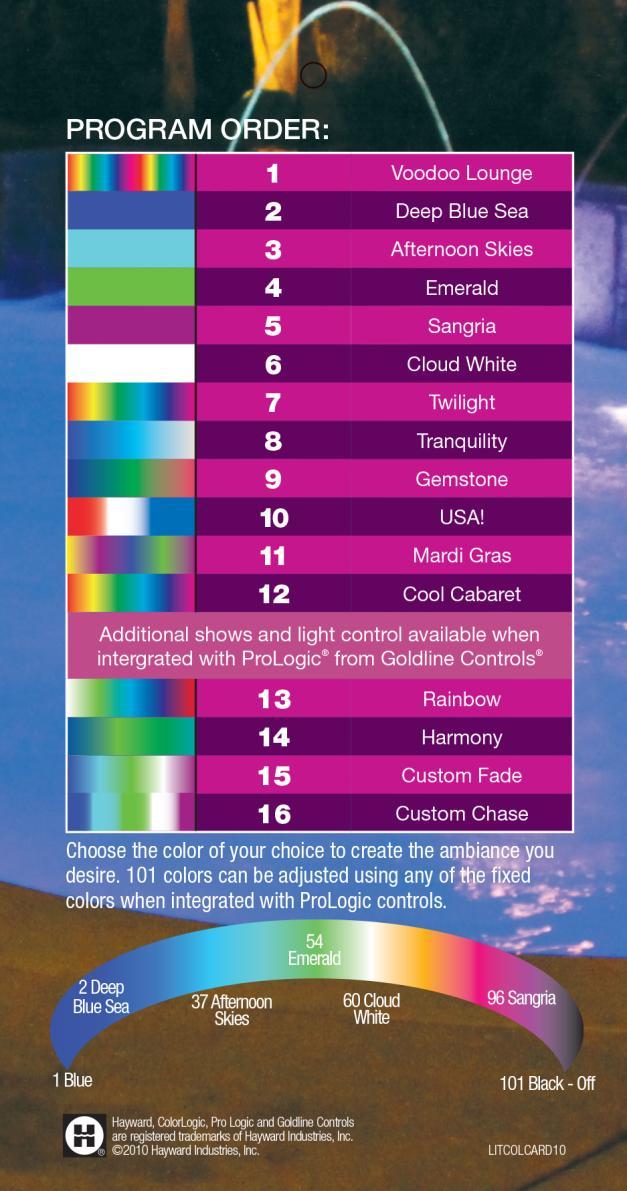
7 LITUCLCARD11 LITCOLCARD09 Additional shows available using module mode. Page 5


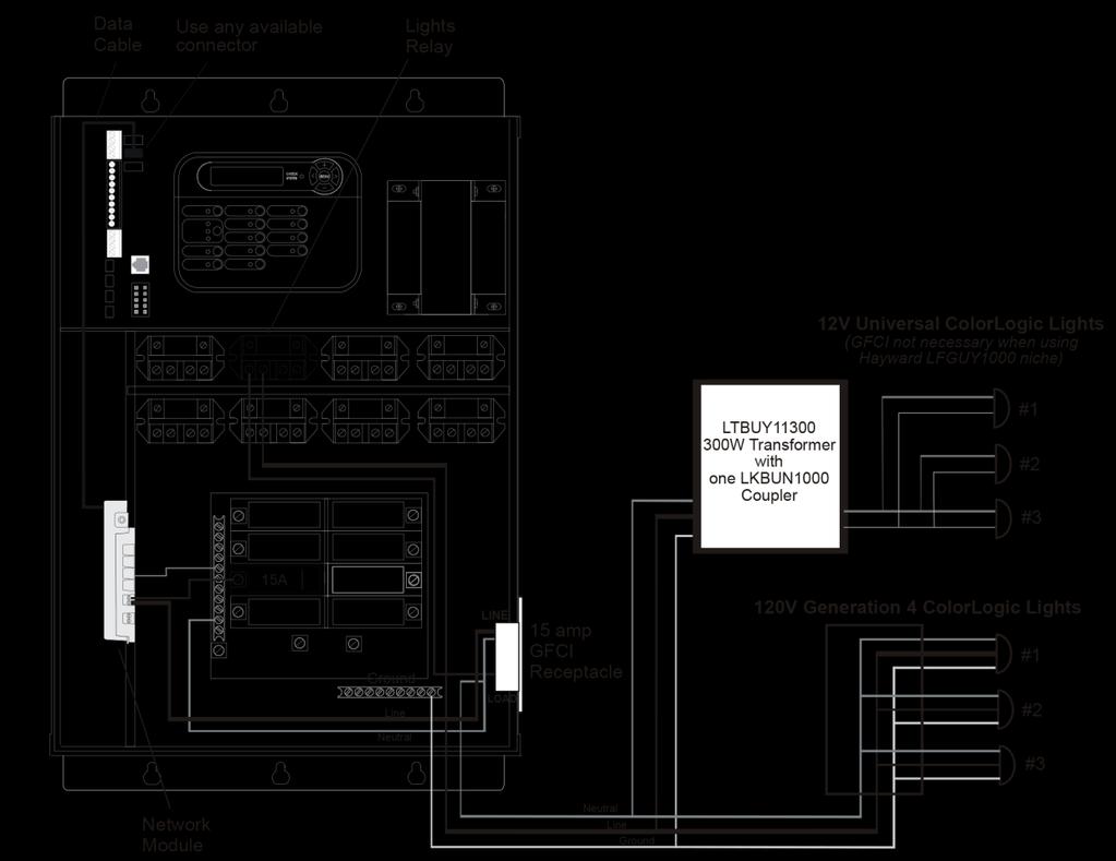
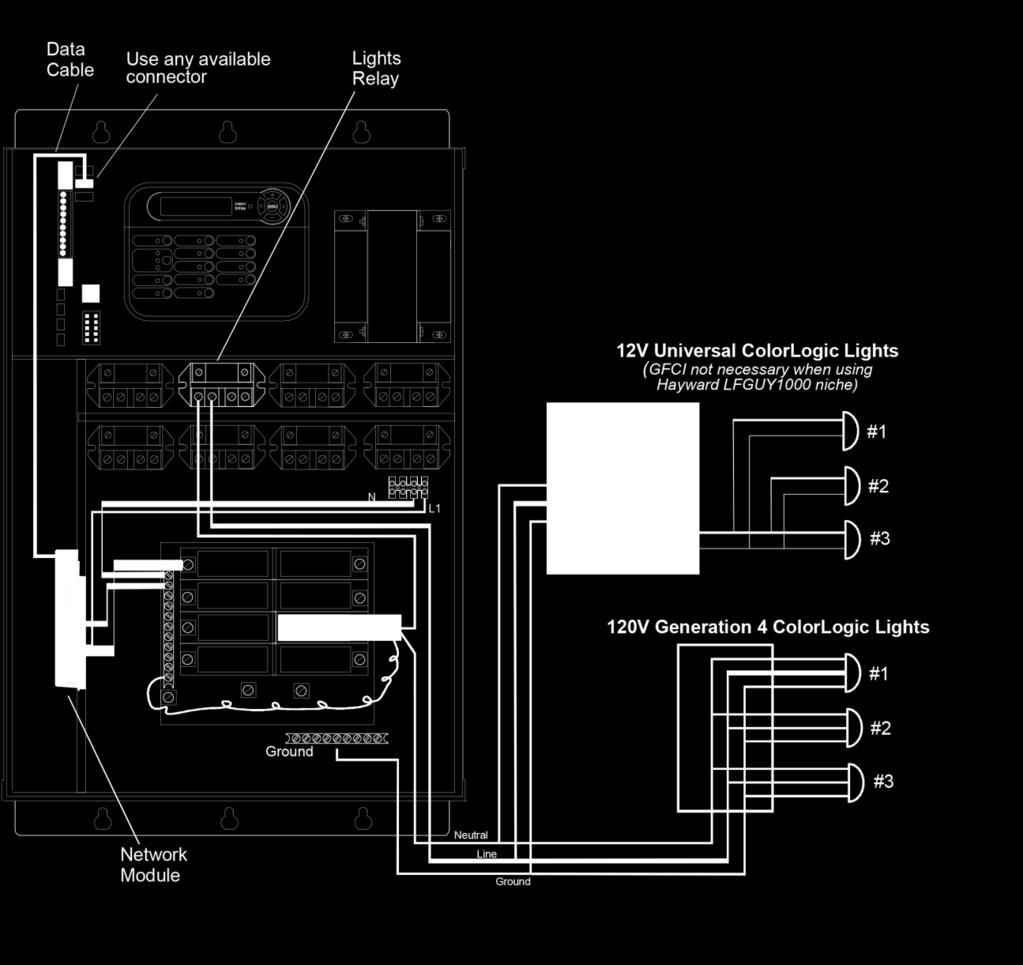
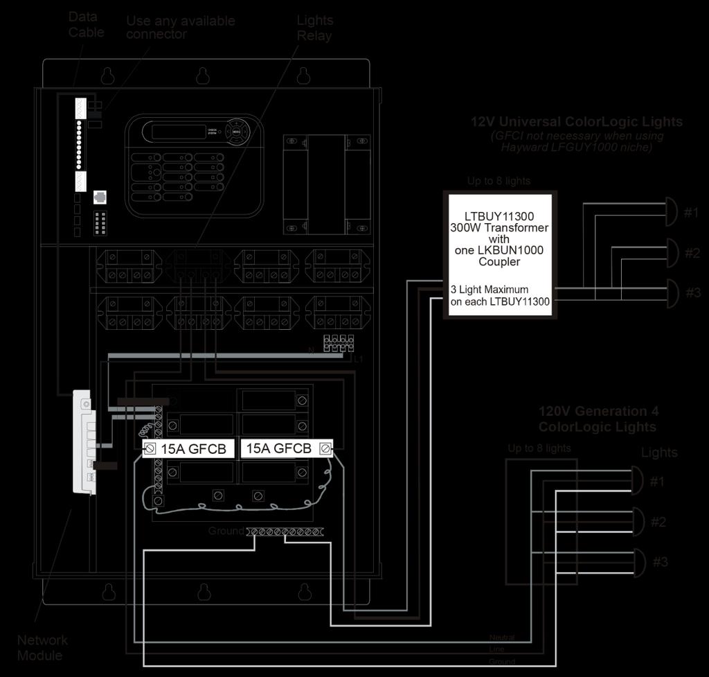
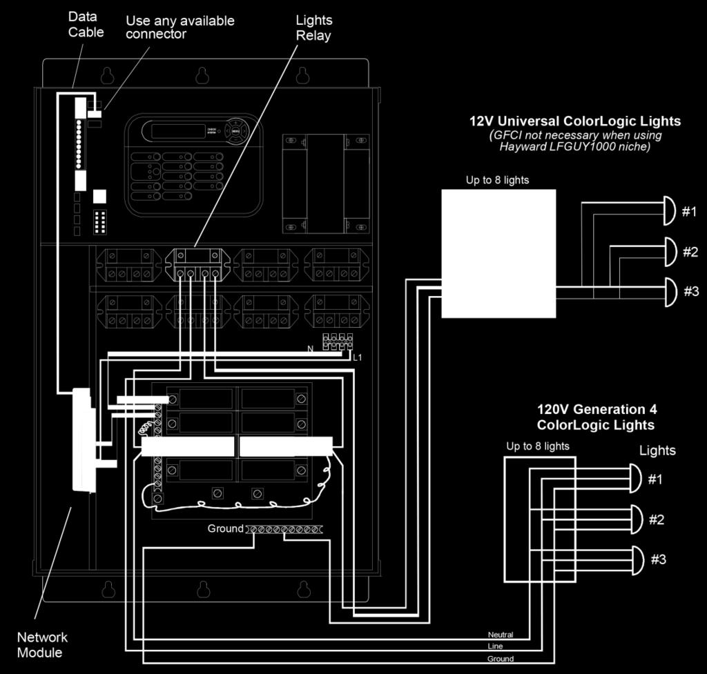
8 Wiring Diagram (Networked) Network Lights Application Coupler 120VAC Input 120VAC Input 14Volt UCLs Output To 14Volt UCLs Output **Important: For UCL LEDs the low voltage side must be tapped into the 14VAC circuit.** Page 6


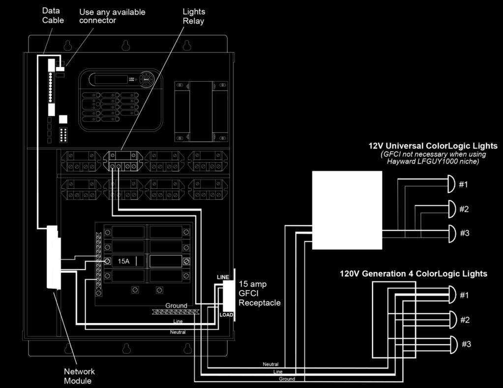
9 Wiring Diagram (Networked) Network Lights Application 14Volt UCLs Output Coupler 120VAC Input 14Volt UCLs Output 120VAC Input Page 7


10 Step A Remove the plastic plate by sliding it towards the front of the enclosure. Step B Holding the modem at an angle, insert the top of the modem into the cutout. Step C Insert the bottom of the modem in place and rotate the modem until it seats into the cutout. Page 8
.")
11 The ColorLogic Network Module uses 120VAC power line communications to individually control each networked light (communicating over the neutral). The same bus must be used to power both the Network Module and any networked light(s). L2 L1 L2 L1 NOTE: When using more than one circuit breaker to power Lights, be sure that the breakers AND the Network Module feed are on the same power bus. Page 9


12 Step D Connect neutral wire (white) from module to neutral bus bar of controller. Step E Connect load power wire (black) from breaker to module. Step F Connect data cable from module to any open Comm connector on PCB. Page 10

 and load power wire (to lights)")

13 Step G Connect the pig-tail wire of the GFCI breaker to the neutral bus bar. Step H Connect the line power wire (from breaker) and load power wire (to lights) to the Lights Relay. Step I Connect the load neutral wire (from light) to the GFCI breaker. Page 11


14 During ColorLogic configuration, the Pro Logic will find all networked lights in the system and assign an identification number to each using the prefix "LT". Step J Press the + button to activate ColorLogic options Step K Press the + button to find ColorLogic lights Note: Once the ColorLogic configuration process begins, there is no way to exit and the process must be completed. Page 12


15 Step L Power cycles to the ColorLogic light(s), may take 1 minute or more. Do not press any buttons while waiting. Step M Push the right arrow button to advance. The system is now searching for installed lights. The lights may blink several times during this process. If all installed lights are not found, check wiring and configure/find lights again. If problem persists, Refer to UCL/ColorLogic 4.0 Troubleshooting Guide. Search for ColorLogic light(s), may take up to 5 minutes Page 13


16 After all lights are found, each light will need to be assigned an identification number. These numbers will be shown as LT1,LT2, LT3..., depending on how many lights are found. The number will identify the light for all future programming of shows, colors, etc. Step N The light being assigned will blink to help identify the specific light. To change the light #, press the + or button. Then press the right arrow button to assign the next light. Step O The message below will be displayed if key presses are made prior to the module storing the previous information. Simply wait a moment and try again. Page 14


17 The ColorLogic lights configuration can be reset if desired. Use this procedure when: -adding a light to the system -removing a light from the system -re-assigning a LT number to an existing light Step P In the configuration menu, Initiate reset of all ColorLogic configuration parameters by pressing the + key Step Q Reset all ColorLogic configuration parameters by pressing the + key. ColorLogic lights are been reset. Move to the next menu item by pressing the right arrow key. Page 15
.")
18 Any Aux output can be configured to control a ColorLogic fixed color or light show, (Aux 4 is used for example in this guide). A virtual Aux output can also be used on Pro Logic Virtual models (see the Pro Logic manual for more information). A ColorLogic light can be assigned to more than one Aux and if more than one show is desired, additional Aux outputs can be configured Step Q Select the desired Aux and press +. Step R Scroll thru the list of available names using the + and buttons. Select the name you want displayed and press the right arrow button. Step S Select the function for how the Aux will operate ( Manual, Timeclock, or Countdown). Press the right arrow button to move to the next step. Page 16

19 Step R Press the + or button until ColorLogic is display as relay type. Then press the right arrow key. Step S The system will now ask individually if each light found should be assigned to the Aux. The default answer is no. Press + or to change to yes. Then press the right arrow button. Step T For each light assigned, Press the + or button to determine the display sequence it will have with others in the Aux being programmed. Press the right arrow key to move to the next light. Note: Multiple lights can have the same sequence. Page 17

20 Light shows and fixed colors are programmed differently and will require different input from the user. Programming the ColorLogic lights takes place within the Settings Menu of the Pro Logic control. To enter the Settings Menu, push the "Menu" button until "Settings" is displayed. Push the "<" or ">" buttons until the desired Aux is displayed then follow the sequence described on the following pages. Step U Select the desired Aux and press +. Step V Step W Press + or buttons to toggle between all available light shows and fixed color options. Press the right arrow to move to the next step. Press + or buttons to toggle between all available speeds. Press the right arrow to move to the next step. Page 18
21 Step X Press + or buttons to toggle between all available motion options. Press the right arrow to move to the next step. Note: When motion is set to OFF, there is no delay and all lights will illuminate at the same time. When motion is set to a positive value (+0.2 to +1.2), the order of illumination will start from the lowest LT number and advance to the highest. If a negative motion value is selected (-1.2 to - 0.2), the illumination sequence will be the opposite (highest LT to lowest). Step Y Press + or buttons to toggle between all available brightness options. Press the right arrow to move to the next step. Page 19
22 Step Z Select the desired Aux and press +. Step AA Press + or buttons to toggle between all available light shows and fixed color options. Press the right arrow to move to the next step. Step AB Press + or buttons to toggle between all available colors of fixed light.. Step AC Press the right arrow button twice to move to the next step, FF. Press the + button to reset factory settings (Step AD). Page 20


23 Step AD Press the + button to reset to fixed color default. Step AE Press the right arrow button to move to next step. Step AF Press the + or - button to move to adjust the brightness setting. Press the right arrow button to the next menu item. This completes the setting of the colors. To exit, press the menu button. Page 21
24 Why is my UCL light flashing in white? This can be explained by one of the following: Normally caused by voltage drop, some reasons Wrong voltage from a wall mount transformer (needs to be 14V if longer than 50ft) Non pool transformer that does not support 14V Cord run from the transformer to the ultimate light too long Single low gauge run to multiple lights from the transformer to the JBox Low utility input voltage Too many lights (more than 3) are installed on the transformer Why is my light flashing in many colors? Usually an indication that a junction box transformer that is operating in White or a Color Show in ambient outdoor temps north of 95 degrees at night. Why is my light dimming? Light is not installed in the water or pool water is hotter than 100 degrees. Page 22
25 Even when the lights are off, why does the Lights indicator on the Pro Logic control panel always turn on whenever the Pro Logic is turned on? The Lights indicator reflects the state of power to the lights and power is always applied to the lights when the pool controller is on. The lights run a light show, turn on, or turn off under program control which is initiated from the Pro Logic. In general, lights will have power applied even if the lights are not displaying visible light. Can the Lights relay be configured when used with a ColorLogic Lights Generation 4.0 (CLLG4) system? No, the Pro Logic automatically assigns the Lights relay to the CLLG4 system and enables power to the light. Lights are always powered when the pool controller is powered on. To force this relay off, use Service Mode or System Off mode. How does the Lights button work? The Lights button is used for emergency white lighting of the pool. The Lights button sends a command to toggle the light state. The lights will either turn on (full white) or off. If you press the button and the lights remain off, press the button again to turn the lights on full white. If you press the button and the lights stay on, press the button again to make the lights turn off. Normal color operation of the lights is done through Aux buttons. Page 23
26 Can lights be assigned to multiple Aux buttons? Yes, different light shows can be set up for each Aux button. For instance, a light can be assigned to Aux 1 and Aux 2. Aux 1 can be set to Voodoo Lounge while Aux 2 can be set to Deep Blue Sea. What happens when lights are assigned to multiple Aux buttons? Lights process the command associated with the last button which was turned on. Do all lights have to be assigned to the same Aux button? No, a subset of lights can be assigned to any Aux button. For instance, if you are using a Pro Logic with eight Aux buttons, pool lights can be assigned to Aux 4 and spa lights can be assigned to Aux 5. If Aux 4 and Aux 5 are set up this way, different light shows can be assigned to Aux 4 and Aux 5. Moreover, if lights are separated between pool and spa, both the pool and spa lights can run different light shows at the same time. Another Aux can run all the lights at once. Can light show settings be changed while a show is running? Yes, the settings for a show can be changed while a show is running. If you pause a few seconds between key presses, you will be able to see the effect of the changes while the show is running. Page 24
27 How do lights go from stand alone mode to program control mode? Lights are originally shipped in stand alone mode. This mode allows the light shows to be controlled using power line interrupts (toggling power to the light) and is similar to the previous generation lights. The lights automatically go into program control mode when they are configured with a Pro Logic pool controller and AQL-COLOR- MODHV. How do lights go from program control mode to stand alone mode? Lights which have been installed and configured with a pool controller can be returned to stand alone mode by using the Reset ColorLogic option in the Pro Logic configuration menu. You also will need to remove the network module and move the lights input and output power to another relay. Can I mix ColorLogic 4.0 lights with ColorLogic 2.5 lights in stand alone mode? No, the timing of light shows in version 4.0 lights is not the same as version 2.5 lights. The lights will not perform at the same speed or intensity. Can I mix ColorLogic 4.0 lights with UCL in stand alone or Module control? Yes, for stand alone mode the UCL lights will have to be set to 4.0 mode. For module control no additional steps are necessary. Page 25

28 Page 26
29 Page 27
30 Page 28
ColorLogic 4.0 Installation Guide
 ColorLogic 4.0 Installation Guide Copyright 2011 Hayward Industries Table of Contents Safety Precautions Page 1 Overview Page 2 Program Table Page 3 Network Module Installation Page 4 Wiring Lights Pages
VS Technical Guide Hayward Pool Products. Version 1 Display Rev: 1.01 Comm Rev: 0.96 Drive Rev: 2.00.oz
 TriStar VS Technical Guide 2014 Hayward Pool Products Version 1 Display Rev: 1.01 Comm Rev: 0.96 Drive Rev: 2.00.oz Table of Contents Safety Precautions Page 1 Overview Page 2 Installation- Plumbing Page
IntelliBrite Controller (For IntelliBrite Pool, Spa and Landscape Lighting Fixtures)
") IntelliBrite Controller (For IntelliBrite Pool, Spa and Landscape Lighting Fixtures) Installation and User s Guide IMPORTANT SAFETY INSTRUCTIONS READ AND FOLLOW ALL INSTRUCTIONS SAVE THESE INSTRUCTIONS
IntelliBrite Controller (For IntelliBrite Pool, Spa and Landscape Lighting Fixtures) Installation and User s Guide IMPORTANT SAFETY INSTRUCTIONS READ AND FOLLOW ALL INSTRUCTIONS SAVE THESE INSTRUCTIONS
IntelliBrite Controller (For IntelliBrite Pool, Spa and Landscape Lighting Fixtures) Installation and User s Guide
 Installation and User s Guide") IntelliBrite Controller (For IntelliBrite Pool, Spa and Landscape Lighting Fixtures) Installation and User s Guide *619751* P/N 619751 - Rev B IMPORTANT SAFETY INSTRUCTIONS READ AND FOLLOW ALL INSTRUCTIONS
IntelliBrite Controller (For IntelliBrite Pool, Spa and Landscape Lighting Fixtures) Installation and User s Guide *619751* P/N 619751 - Rev B IMPORTANT SAFETY INSTRUCTIONS READ AND FOLLOW ALL INSTRUCTIONS
Sidewinder Pumps Inc. AC Timer/Controller
 Sidewinder Pumps Inc. AC Timer/Controller Page 1 of 12 Rev 032417 Table of Contents 1. Warnings-------------------------------------------------------------------------------------------------- 3 1.1.
Installation, Testing, and Operating Procedures 30 AMP PORTABLE AND PERMANENT SERIES GFCI SINGLE and MULTIPHASE
 IMPORTANT! Please read all the information on this sheet. SAVE THESE INSTRUCTIONS! NOTICE BEFORE USING READ INSTRUCTIONS COMPLETELY. TO BE INSTALLED BY A QUALIFIED ELECTRICIAN IN ACCORDANCE WITH NATIONAL
AquaConnect. Troubleshooting Guide Residential. TSG-ACHN110d. Copyright 2017 Hayward Industries Inc.
 AquaConnect Troubleshooting Guide Residential TSG-ACHN110d Copyright 2017 Hayward Industries Inc. Safety Precautions Warning! High Voltage Electrocution Hazard Hazardous voltage can shock, burn, cause
VS Omni. Consumer How-To Guide. CTSG-VSO100a. Copyright 2018 Hayward Industries Inc.
 VS Omni Consumer How-To Guide CTSG-VSO100a Copyright 2018 Hayward Industries Inc. Safety Precautions Warning! High Voltage Electrocution Hazard Hazardous voltage can shock, burn, cause serious injury and
ELECTRICAL SUPPLY TROUBLESHOOTING QUICK GUIDE SAFETY PRECAUTIONS
 ELECTRICAL SUPPLY TROUBLESHOOTING QUICK GUIDE 1. Circuit Breaker Tripping 2. Circuit Overload 3. Short Circuit 4. Ground Fault 5. Ground Fault Circuit Interrupter (GFCI) Tripping SAFETY PRECAUTIONS Basic
FDS / FDS-R / FDS-PS
 FDS / FDS-R / FDS-PS USER MANUAL For use with 120V 60Hz input. Output is 120V 60Hz at 5amps 600W MAX. switched. ETL LISTED Conforms to UL STD 1241 3091594 79-15167-00 REV. A www.fiberstars.com Page 1 of
A0/A1 Controller Assembly Operation/Installation Manual READ AND FOLLOW ALL SAFETY INSTRUCTIONS
 Document Number: 9100-127-2301-99 Release Date: 2/2/15 A0/A1 Controller Assembly Operation/Installation Manual READ AND FOLLOW ALL SAFETY INSTRUCTIONS DO NOT let any supply cords touch hot surfaces higher
Instruction Manual. M Pump Motor Controller. For file reference, please record the following data:
 Instruction Manual M Pump Motor Controller For file reference, please record the following data: Model No: Serial No: Installation Date: Installation Location: When ordering replacement parts for your
QuickTouch (QT4) Owner s Manual
 Owner s Manual") QuickTouch (QT4) Owner s Manual 4-Function Hand-Held Wireless Remote Control IMPORTANT SAFETY INSTRUCTIONS READ AND FOLLOW ALL INSTRUCTIONS SAVE THESE INSTRUCTIONS Table of Contents SECTION I. APPLICATION...
QuickTouch (QT4) Owner s Manual 4-Function Hand-Held Wireless Remote Control IMPORTANT SAFETY INSTRUCTIONS READ AND FOLLOW ALL INSTRUCTIONS SAVE THESE INSTRUCTIONS Table of Contents SECTION I. APPLICATION...
Electrical Management System (EMS) EMS-HW30C & EMS-HW50C
 EMS-HW30C & EMS-HW50C") Electrical Management System (EMS) EMS-HW30C & EMS-HW50C Installation & Operating Guide for: Model EMS-HW30C Rated at 120V/30A and Model EMS-HW50C Rated at 240V/50A Surgio Says Lifetime Warranty on all
Electrical Management System (EMS) EMS-HW30C & EMS-HW50C Installation & Operating Guide for: Model EMS-HW30C Rated at 120V/30A and Model EMS-HW50C Rated at 240V/50A Surgio Says Lifetime Warranty on all
Instruction Manual. Electrical Management System (EMS) EMS-HW30C & EMS-HW50C
 EMS-HW30C & EMS-HW50C") Instruction Manual Electrical Management System (EMS) EMS-HW30C & EMS-HW50C EMS-HW50C EMS-HW30C! CAUTION These instructions are intended to provide assistance with the installation of this product, and
Instruction Manual Electrical Management System (EMS) EMS-HW30C & EMS-HW50C EMS-HW50C EMS-HW30C! CAUTION These instructions are intended to provide assistance with the installation of this product, and
Progressive Industries, Inc. EMS Electrical Management System
 Progressive Industries, Inc. EMS Electrical Management System Complete Installation Guide and Operating Instructions for: Model EMS-LCHW50 Rated at 240V/50A Manufactured by: Progressive Industries, Inc.
TT /12b INSTALLATION INSTRUCTIONS. Introduction
 TT-1545 11/12b INSTALLATION INSTRUCTIONS Original Issue Date: 6/10 Model: 20-300 kw Generator Sets Market: Industrial Subject: Decision-Maker 3000 Controller Service Replacement Kit GM75376 Introduction
Measure Ø-N, Ø-Ø, Ø-Gnd with voltmeter to confirm application voltage prior to installation.
 Product No. 99-600-91 Rev. B Page 1 of 8 MCG Surge Protection Model 160MXT Installation Instructions Important Warranty Information MCG surge protectors are designed to work at specific voltages and configurations,
COMFORT CONTROL CENTER SERVICE INSTRUCTIONS
 USA SERVICE OFFICE Dometic Corporation 2320 Industrial Parkway Elkhart, IN 46516 574-294-2511 CANADA Dometic Corporation 46 Zatonski, Unit 3 Brantford, ON N3T 5L8 CANADA 519-720-9578 For Service Center
SERIES 5100 INSTALLATION & SPECIFICATION GUIDE
 SERIES 5100 INSTALLATION & SPECIFICATION GUIDE Microframe Corporation 604 South 12th Street Local: 918-258-4839 Toll Free: Website: www.microframecorp.com E-mail: support@microframecorp.com Manual No.
SAVE THESE INSTRUCTIONS
 READ AND FOLLOW ALL SAFETY INSTRUCTIONS! SAVE THESE INSTRUCTIONS AND DELIVER TO OWNER AFTER INSTALLATION IMPORTANT SAFEGUARDS! When using electrical equipment, basic safety precautions should always be
M250 (M LL) Safety
 Safety") M250 SAFETY M250 (M250-60-2LL) Safety Important Safety Information This document contains important instructions to use during installation of the Enphase M250 Microinverter. To reduce the risk of electrical
M250 SAFETY M250 (M250-60-2LL) Safety Important Safety Information This document contains important instructions to use during installation of the Enphase M250 Microinverter. To reduce the risk of electrical
ETC Installation Guide
 Unison Foundry Overview The Unison Foundry provides fully-rated 20A relays for switched power control with 0 10V dimming for compatible fluorescent ballasts and LED drivers. The provides two outputs of
SERIES 5100XXX8 INSTALLATION & SPECIFICATION GUIDE
 SERIES 5100XXX8 INSTALLATION & SPECIFICATION GUIDE Microframe Corporation 604 South 12th Street Local: 918-258-4839 Toll Free: Website: www.microframecorp.com E-mail: support@microframecorp.com Revision
Blue Box BLUE BOX TM LTD PARTS REPLACEMENT GUIDE
 Blue Box BLUE BOX TM LTD PARTS REPLACEMENT GUIDE WARNINGS 1. All servicing should be performed by qualified service personnel. 2. WARNING, Battery may explode if mistreated. Do not recharge, disassemble
Overview These instructions are presented as a guideline for installing and setting up the LX Series Breaker Control Panel.
 LX Breaker Control Panels Installation and Setup Procedure Hubbell Building Automation, Inc. 9601 Dessau Road Building One Suite 100 Austin, Texas 78754 512-450-1100 512-450-1215 Fax www.hubbell-automation.com
Sidewinder Pumps Inc. AC C1D2 Timer/Controller
 Sidewinder Pumps Inc. AC C1D2 Timer/Controller Page 1 of 14 Rev 4/26/17 Table of Contents 1. Warnings --------------------------------------------------------------------------------------------------
Instruction Manual HPH-8
 Specifications HPH-8 Trigger cable 120-volt, Nema 1-15 Main Power 50-amps @ 240-volt AC Power receptacles (4) Nema 5-15 or 6-15 Maximum HID wattage 8000 watts (on 240-volt) 4800 watts (on 120-volt) Maximum
M215-Z Safety Information (M LL-IG-ZC)
") M215-Z SAFETY M215-Z Safety Information (M215-60-2LL-IG-ZC) This document contains important instructions to use during installation of the M215-Z Zep Compatible Microinverters. To reduce the risk of electrical
M215-Z SAFETY M215-Z Safety Information (M215-60-2LL-IG-ZC) This document contains important instructions to use during installation of the M215-Z Zep Compatible Microinverters. To reduce the risk of electrical
Mitsubishi Electric Automation Instruction Manual FR-A5AC-01
 Mitsubishi Electric Automation Instruction Manual FR-A5AC-01 AC Input Interface Option Unit NOTE: CAUTION: WARNING: NOTES, CAUTIONS AND WARNINGS Notes are used to provide additional detail about a procedure.
M215 (M215-60) Safety
 Safety") M215 QUICK INSTALL GUIDE M215 (M215-60) Safety Important Safety Information This document contains important instructions to use during installation and maintenance of the Enphase M215 Microinverter. To
M215 QUICK INSTALL GUIDE M215 (M215-60) Safety Important Safety Information This document contains important instructions to use during installation and maintenance of the Enphase M215 Microinverter. To
MEGA DIAL PANEL Instructions
 2036 Fillmore Street Davenport, Ia. 52804 563-324-1046 www.racedigitaldelay.com MEGA DIAL PANEL Instructions WARRANTY AND DISCLAIMER DIGITAL DELAY ELECTRONICS INC. WARRANTS THE PRODUCTS IT MANUFACTURES
INSTRUCTION MANUAL E. Sturgis Road, Oxnard CA Phone Fax
 INSTRUCTION MANUAL 2200 E. Sturgis Road, Oxnard CA 93030 Phone 805.981.0262 Fax 805.981.9403 waterway@waterwayplastics.com www.waterwayplastics.com Designed, Engineered & Manufactured in the USA. OASIS
Technical Specificaions. kwh Energy Meter
 Technical Specificaions of kwh Energy Meter (SPK301) Class 1.0S Sai PowerrZerve 29/3B, Rajalakshmi Nagar, 1 st Main Road, Velachery Bye Pass, Chennai 600 042. Website :www.spowerz.com Email : info@spowerz.com
HydroGuard 4 to 20 ma Output Module. For use with HydroGuard Water Quality Monitor and Controller
 HydroGuard 4 to 20 ma Output Module For use with HydroGuard Water Quality Monitor and Controller Technician's Manual Installation, Operation, and Maintenance Guide Chapter 1: Preface... 3 1.1 Intended
ILUMEN PID SOLUTION INDOOR OUTDOOR ILUMEN PIDBOX MINI INSTALLATION MANUAL. Ilumen PIDbox mini Version 1.5
 ILUMEN PID SOLUTION ILUMEN PIDBOX MINI INSTALLATION MANUAL INDOOR OUTDOOR Ilumen PIDbox mini Version 1.5 1 TABLE OF CONTENT 1 Information on this manual... 3 1.1 Validity... 3 1.2 Target group... 3 1.3
EMS. Electrical Management System. Progressive Industries Incorporated Morrisville, North Carolina
 Progressive Industries Warranty Progressive warrants its products are free from defects in materials and workmanship for a period of three years. This is in lieu of all other warranties, obligations, or
24/7 Sprinkler Monitor. The Ultimate Rain/Freeze Sensor
 24/7 Sprinkler Monitor The Ultimate Rain/Freeze Sensor User s Manual PIONEER SALES, LTD. 5529 Redfield St. Dallas, TX 75235 Phone: (214) 276-0306 Fax: (214) 631-4218 Toll Free: 1-(866) 501-7745 1 Table
HAIKU WALL CONTROL KIT
 0 1 2 3 4 5 6 7 8 9 A B C D E F ON 1 2 3 4 HAIKU by BIG ASS FANS HAIKU WALL CONTROL KIT WARNING: Ensure power is disconnected at the fuse/breaker distribution panel before installing or servicing the wall
Dim levels for each system output may be controlled by either of the following methods:
 Applied Electronics Bravo Series Dimming System Model SA12/1200 Setup and Operation Instructions 1.0 Scope This document details the setup and operation requirements for Applied Electronics Bravo Series
LITETOUCH HYBRID WALL BOX DIMMER INSTALLATION INSTRUCTIONS
 READ INSTRUCTIONS PRIOR TO INSTALLATION OF EQUIPMENT OR YOU MAY VOID THE WARRANTY! LITETOUCH INSTALLATION INSTRUCTIONS The LiteTouch Hybrid Wall Box Dimmer is a configurable lighting control device, that
USER MANUAL INSTALLATION MANUAL. Isolation transformers. ITR Isolation Transformer 7000 W 230V/32A
 USER MANUAL INSTALLATION MANUAL Isolation transformers ITR000702000 Isolation Transformer 7000 W 230V/32A Victron Energy B.V. The Netherlands General phone: +31 (0)36 535 97 00 Customer support desk: +31
SPECIAL INSTRUCTIONS FOR CAPACITORS COMPACT GENERATORS
 SPECIAL INSTRUCTIONS FOR CAPACITORS COMPACT GENERATORS (WITH CAPACITOR CHARGER BOARD A3517-02) The process depends on Generator and System configuration. This document applies to installation of Capacitors
ETC Installation Guide
 ColorSource PAR v1.7 Overview The ColorSource PAR is an affordable LED fixture that uses the RGB-L (red, green, blue, and lime) color system to provide a rich, bright light. The ColorSource PAR is available
Dim levels for each system output may be controlled by any of the following methods:
 Applied Electronics Bravo Series Dimming System Rack-Mount Architectural l SA12/2400A and l SA12/2400E Setup and Operation Instructions 1.0 Scope This document details the setup and operation requirements
BCM2 Series Branch Circuit Monitors Quick Setup Guide
 BCM2 Series Branch Circuit Monitors Quick Setup Guide Safety Information DANGER! HAZARD OF ELECTRIC SHOCK, EXPLOSION, OR ARC FLASH Follow safe electrical work practices. See NFPA 70E in the USA, or applicable
Instruction Sheet Board Style Low Water Cutoff
 Instruction Sheet Board Style Low Water Cutoff 102-305 SUPERSEDES: REVISION E DATED December 12, 2007 #5401173-REV F PLANT ID 001-3902 US Patents 6,904,800, 7,243,540, and 7,317,993 Other Patents Pending
Satellite INSTALLATION GUIDE
 N3 Satellite INSTALLATION GUIDE ! WARNING! Shock Hazard. May result in serious injury or death. Turn power OFF at circuit breaker or remove fuse. Damage to this product caused by wiring with power on voids
AE21 SERIES DISPLAY CONTROL TERMINAL
 FN:AE21MAN1.DOC AE21 SERIES DISPLAY CONTROL TERMINAL DESCRIPTION The AE21 Series Display Control Terminal is used for implementing various display functions. It consists of a control terminal, the AE21,
SAVE THESE INSTRUCTIONS
 OUTDOOR HARDWIRE INSTALLATION INSTRUCTIONS Please read and save these instructions. Read carefully before using product. Protect yourself and others by observing all safety information, warnings and cautions.
Panduit Basic Rack PDU with Local Meter
 Panduit Basic Rack PDU with Local Meter User Manual Release 1.0 Issue 1.0 Copyright 2014 Panduit Corp. All rights reserved. No part of this book shall be reproduced, stored in a retrieval system, or transmitted
Instruction Bulletin. Fiber Optic Switch Packs. SLSPSP101 and SLSPSP102 for use with Luminaires INTRODUCTION CONTENTS OF THE BOX
 Instruction Bulletin 63249-500-04A3 07/2010 Fiber Optic Switch Packs SLSPSP101 and SLSPSP102 for use with Luminaires INTRODUCTION SLSPSP101 Single Input Switch Pack SLSPSP102 Dual Input Switch Pack The
Installation and Operation Back-UPS BR1000G-IN / BR1500G-IN
 Installation and Operation Back-UPS BR1000G-IN / BR1500G-IN Important Safety Information Read the instructions carefully to become familiar with the equipment before trying to install, operate, service
Installation Instructions
 SPECIFICATIONS InteliSwitch Digital Time Switch 24VDC/VAC Voltages...... 24VDC, 24VAC, 24VAC Half Wave Rectified Current Consumption...................Max. 15mA DC.................................Max.
629/P32 (X10/P32) PIC CHIP. On - Off Operating Instructions (Revision 2)
 PIC CHIP. On - Off Operating Instructions (Revision 2)") 629/P32 (X10/P32) PIC CHIP On - Off Operating Instructions (Revision 2) This manual is a living document, therefore it will change when needed to clarify and explain the operation of the 629/P32 (X10/P32)
629/P32 (X10/P32) PIC CHIP On - Off Operating Instructions (Revision 2) This manual is a living document, therefore it will change when needed to clarify and explain the operation of the 629/P32 (X10/P32)
Installation Instructions
 Alliance Arming Station AL-1111, AL-1116 1048520C September 2006 Copyright 2006, GE Security Inc. Introduction This is the GE Alliance Arming Station for models AL-1111 (four-line LCD) and AL-1116 (four-line
GV3000/SE Operator Interface Module (OIM) User Guide Version 2.0 M/N 2RK3000
 User Guide Version 2.0 M/N 2RK3000") GV3000/SE Operator Interface Module (OIM) User Guide Version 2.0 M/N 2RK3000 Instruction Manual D2-3342-2 The information in this manual is subject to change without notice. Throughout this manual, the
GV3000/SE Operator Interface Module (OIM) User Guide Version 2.0 M/N 2RK3000 Instruction Manual D2-3342-2 The information in this manual is subject to change without notice. Throughout this manual, the
HomePro ZRF113. Z-Wave Radio Frequency (RF) Controlled, 120 VAC, Isolated Contact Fixture Module, Series 200, Release 2.2
 Controlled, 120 VAC, Isolated Contact Fixture Module, Series 200, Release 2.2") RF Home Automation ZRF113 Z-Wave Radio Frequency (RF) Controlled, 120 VAC, Isolated Contact Fixture Module, Series 200, Release 2.2 Note: This module must be Included in the Network only where it will
RF Home Automation ZRF113 Z-Wave Radio Frequency (RF) Controlled, 120 VAC, Isolated Contact Fixture Module, Series 200, Release 2.2 Note: This module must be Included in the Network only where it will
GLOBRITE COLOR CHANGING UNDERWATER LED LIGHT FOR POOL AND SPA
 GLOBRITE COLOR CHANGING UNDERWATER LED LIGHT FOR POOL AND SPA INSTALLATION AND USER S GUIDE IMPORTANT SAFETY INSTRUCTIONS READ AND FOLLOW ALL INSTRUCTIONS SAVE THESE INSTRUCTIONS ii Technical Support Phone:
Enphase S-Series Microinverter and Engage Cable Safety
 SAFETY Enphase S-Series Microinverter and Engage Cable Safety Important Safety Information (S280-60-LL and S230-60-LL) This document contains important instructions to use during installation of the Enphase
RF Wireless LED Remote Dimmer Controller Model: DIM Two Colors Dimmer / 6 Zones / 6 Options to save
 RF Wireless LED Remote Dimmer Controller Model: DIM 700 1001 Two Colors Dimmer / 6 Zones / 6 Options to save 20725 NE. 16 AVE. #A-33 MIAMI, FLORIDA 33179 TEL: (305) 652-2599 FAX: (305) 650-8812 WWW.LUMIRON.COM
M215 Safety (M LL-S22-IG / S23-IG / S24-IG)
") M215 SAFETY M215 Safety (M215-60-2LL-S22-IG / S23-IG / S24-IG) Important Safety Information This document contains important instructions to use during installation of the Enphase M215 Microinverter. To
M215 SAFETY M215 Safety (M215-60-2LL-S22-IG / S23-IG / S24-IG) Important Safety Information This document contains important instructions to use during installation of the Enphase M215 Microinverter. To
Pulse LED Instruction Guide
 PARTS LIST Light Fixture Aquarium Frame Mounts Instruction Guide WARNING: To guard against injury, basic precautions should be observed, including the following: A) READ AND FOLLOW ALL SAFETY INSTRUCTIONS.
INSTALLATION INSTRUCTIONS
 TM REPLACEMENT PARTS FOR USE WITH CX SERIES PANELS INSTALLATION INSTRUCTIONS Hubbell Control Solutions 9601 Dessau Road Building One Suite 100 Austin, TX 78754 Toll Free: 888-698-3242 Fax: 512-450-1215
PNP415/417 POP 'N PLUG WITH CUSTOM TABLETOP SURFACE USER'S GUIDE
 PNP415 PNP417 with tabletop cutout installed. MANUAL PART NUMBER: 400-0427-002 PNP415/417 POP 'N PLUG WITH CUSTOM TABLETOP SURFACE USER'S GUIDE TABLE OF CONTENTS Page PRECAUTIONS / SAFETY WARNINGS... 2
Technical Specifications. Dual Source kwh Energy Meter
 Technical Specifications of Dual Source kwh Energy Meter (SPKG300) Class 0.5S Sai PowerrZerve 29/3B, Rajalakshmi Nagar, 1 st Main Road, Velachery Bye Pass, Chennai 600 042. Website :www.spowerz.com Email
QUICK SETUP GUIDE. BCM2 Series Branch Circuit Monitors. Safety Information. Equipment Maintenance and Service. Raritan DANGER!
 QUICK SETUP GUIDE BCM2 Series Branch Circuit Monitors Safety Information DANGER! HAZARD OF ELECTRIC SHOCK, EXPLOSION, OR ARC FLASH Follow safe electrical work practices. See NFPA 70E in the USA, or applicable
For Models #2384W/I (and Slave Remote Dimmer Model #1135W/I)
") SwitchLinc Lite Remote Control Dimmer Switch Owner s Manual For Models #2384W/I (and Slave Remote Dimmer Model #1135W/I) CONGRATULATIONS! You ve just purchased the highest quality powerline-controllable
SwitchLinc Lite Remote Control Dimmer Switch Owner s Manual For Models #2384W/I (and Slave Remote Dimmer Model #1135W/I) CONGRATULATIONS! You ve just purchased the highest quality powerline-controllable
4. How to Connect the Fixture 3-Pin and 5-Pin XLR DMX Connectors:
 TABLE OF CONTENTS 1. Safety Instructions 2. Technical Specifications 3. Installation 4. How to Connect the Fixture 5. DMX512 Configuration 6. DMX512 Connections 7. How to Set the Unit 8. Troubleshooting
Int3233. Soldering Station. Instruction Manual
 Int3233 Soldering Station Instruction Manual Thank you for purchasing the Aoyue int 3233 Soldering Station. Please read the manual before using the unit. Keep manual in accessible place for future reference.
Control Accessories 2011 ZODIAC POOL SYSTEMS CATALOG. ChemLink. Control Accessories. AquaPalm Wireless Handheld Remote
 ChemLink ORP and ph Interface Simplified pool and spa chemistry controller designed for easy installation and operation from an AquaLink RS or PDA system. Adjusts chlorination and ph levels automatically
SERIES 5100XXCX (WITH VOICE ANNOUNCE OPTION) INSTALLATION & SPECIFICATION GUIDE
 INSTALLATION & SPECIFICATION GUIDE") SERIES 5100XXCX (WITH VOICE ANNOUNCE OPTION) INSTALLATION & SPECIFICATION GUIDE Microframe Corporation 604 South 12th Street Local: 918-258-4839 Toll Free: Website: E-mail: support@microframecorp.com Manual
SERIES 5100XXCX (WITH VOICE ANNOUNCE OPTION) INSTALLATION & SPECIFICATION GUIDE Microframe Corporation 604 South 12th Street Local: 918-258-4839 Toll Free: Website: E-mail: support@microframecorp.com Manual
Panorama rudder indicator TRI-2 Analogue or CAN input Approved according to MED Three extra large scales Long-life LED illumination Built-in dimmer
 USER'S MANUAL Panorama rudder indicator TRI-2 Analogue or CAN input Approved according to MED Three extra large scales Long-life LED illumination Built-in dimmer DEIF A/S Frisenborgvej 33 DK-7800 Skive
Model HM-535 Power Supply Installation and Service Instructions
 Model HM-535 Power Supply Installation and Service Instructions 430-535 0104 2004 Heritage MedCall, Inc SENTRY INSTALLATION & SERVICE INSTRUCTIONS POWER SUPPLY UNIT Model HM-535 IMPORTANT SAFETY INSTRUCTIONS
What s in the Box? REAR VIEW SAFETY
 TM 1 What s in the Box? 1 Full HD Color Infra-red Weather Proof Camera 1 Full HD 7" TFT LCD Color Monitor w/monitor Mount 1 Power Harness 1 66 Camera Cable 1 Power Connection Wire 1 Screw Kit for installation
OPERATING INSTRUCTIONS AND SERVICE MANUAL BASKETBALL SHOTCLOCK MODEL MP-5299
 OPERATING INSTRUCTIONS AND SERVICE MANUAL BASKETBALL SHOTCLOCK MODEL MP-5299 EFFECTIVE S.N. 17,000, December, 2000 TABLE OF CONTENTS 1. General Information 1.1 Description 1.2 Identification 1.3 Damage
Safety Control Relay Product Catalog
 Product Catalog Wall Mount for use with Safety Mats Safety Edges Safety Bumpers Safety Sensors 2 wire Safety Sensors 4 wire DIN Rail Mount Intrinsically Safe Explosion Proof Wall Mount Introduction The
EnCell Battery Cell Monitor
 EnCell Battery Cell Monitor Instruction Manual Model RCM15S12 NERC Compliant YO R U H T PA TO Z O R E W O D N M I T E enchargepowersystems.com sales@enchargepowersystems.com (888) 407.5040 Contents 1 Warnings,
PS/IO Circuit Board Retrofit
 S&C 6800 Series Automatic Switch Controls PS/IO Circuit Board Retrofit Table of Contents Section Page Introduction Qualified Persons.... 2 Read this Instruction Sheet.... 2 Retain this Instruction Sheet....
Series 803 LED Product Price Display
 Series 803 LED Product Price Display May 2007 Rev. 1.1 1 Installation and Operation Manual Table of contents 1. Safety.......3 2. Series 803 sign features.......4 2.1 Sign descriptions........4 2.2 Control
INSTEON KeypadLinc TM Dimmer (Rev 1.5+) INSTEON Keypad Dimmer. For models: KeypadLinc Dimmer 8-Button
 INSTEON Keypad Dimmer. For models: KeypadLinc Dimmer 8-Button") INSTEON KeypadLinc TM Dimmer (Rev 1.5+) INSTEON Keypad Dimmer For models: #2486DWH6 #2486DWH8 KeypadLinc Dimmer 6-Button KeypadLinc Dimmer 8-Button TABLE OF CONTENTS ABOUT INSTEON KEYPADLINC DIMMER...4
INSTEON KeypadLinc TM Dimmer (Rev 1.5+) INSTEON Keypad Dimmer For models: #2486DWH6 #2486DWH8 KeypadLinc Dimmer 6-Button KeypadLinc Dimmer 8-Button TABLE OF CONTENTS ABOUT INSTEON KEYPADLINC DIMMER...4
QUICK START. Installation & Programming Guide
 QUICK START Installation & Programming Guide PRECAUTIONS READ AND FOLLOW ALL SAFETY INSTRUCTIONS. CAUTION - RISK OF ELECTRICAL SHOCK. To prevent electrical shock, turn off power at the circuit breaker
OPERATING PROCEDURES for the UPS-S2 Universal Power Supply Series 2
 OPERATING PROCEDURES for the Universal Power Supply Series 2 Vanguard Instruments Co., Inc. 1520 S. Hellman Ave. Ontario, California 91761 TEL: 909-923-9390 November 2013 FAX: 909-923-9391 REV. 2 SAFETY
Installing and Configuring Rialto Analytic Appliances
 Installing and Configuring Rialto Analytic Appliances Important Safety Information This manual provides installation and operation information and precautions for the use of this camera. Incorrect installation
Tornado F-5. Motor Backspin Detect Relay And Probe For F-5 Motor Controller
 Tornado F-5 Motor Backspin Detect Relay And Probe For F-5 Motor Controller Tornado F-5 Motor Backspin Detection Relay And Probe Revision 8.1 Change Log: Rev 8.1 Apr 24 2012 JNesbitt@GPS-US.co GPS updates
INSTRUCTION/INSTALLATION SHEET lyriq High Performance Keypad Volume Control With IR
 1. Introduction The Volume Control with IR, P/N AU1000-xx (see Figure 1), is an integral part of the lyriq Multi-Room Audio System. It is a component which, when combined with other essential components
CS5100DV Tech Sheet. Cal Spas. System PN System Model # VSP-CS5100DV-BCAH Software Version # 46 EPN # 3288
 CS5100DV Tech Sheet Cal Spas System PN 55736-01 System Model # VSP-CS5100DV-BCAH Software Version # 46 EPN # 3288 Base PCBA - PN 55737-01 PCB VS500DVH - PN 23928 Rev A Base Panels VL260 PN 54754-03 with
HUBBELL SPIKESHIELD Wired-In Branch Panels Surge Protective Device (SPD)
") HUBBELL SPIKESHIELD Wired-In Branch Panels Surge Protective Device (SPD) Instruction Bulletin 8222-0513B Retain for future use. SPIKESHIELD Wired-In Branch Panels 8222-0513B 05/2012 Table of Contents Precautions...
HUBBELL SPIKESHIELD Wired-In Branch Panels Surge Protective Device (SPD) Instruction Bulletin 8222-0513B Retain for future use. SPIKESHIELD Wired-In Branch Panels 8222-0513B 05/2012 Table of Contents Precautions...
1 Safety instructions. 2 Intended use. 3 Product characteristics. 4 Operation. LB management. Universal rotary dimmer LED
 Art. no.: 1731DD Operating instructions 1 Safety instructions Electrical devices may only be mounted and connected by electrically skilled persons. Serious injuries, fire or property damage possible. Please
MicroTech III Water Source Heat Pump BACnet MS/TP Communication Module
 Installation and Maintenance Manual IM 928- Group: Controls Part Number: 66920770 Date: July 2009 Supersedes: IM 928 MicroTech III Water Source Heat Pump BACnet MS/TP Communication Module NOTICE Use this
M2 OLED Temperature Monitor Instructions PN 1841
 M2 OLED Temperature Monitor Instructions PN 1841 Installation Checklist Check for components included Read Warning and Cautions Read page 3 for mounting instructions Read System Overview, Mounting Considerations,
high RESISTANCE STOPLIGHT Instruction Manual C-101EM
 stoplight high RESISTANCE GROUNDING SYSTEM STOPLIGHT Instruction Manual C-101EM high resistance grounding protection The StopLight system uses a unique indicator light system to provide visual detection
AEXX SERIES MULTI-FUNCTION CLOCK/TIMERS
 FN:XXMFCT1.DOC AEXX SERIES MULTI-FUNCTION CLOCK/TIMERS AEXX SERIES MULTI-FUNCTION CLOCK/TIMERS REV 04/09/09 DESCRIPTION The AEXX Series of Multi-Function Clock/Timers are available with 1, 2.3, 4, 8, or
Electrical Management System (EMS) EMS-HW30C & EMS-HW50C
 EMS-HW30C & EMS-HW50C") Electrical Management System (EMS) EMS-HW30C & EMS-HW50C Installation & Operating Guide for: Model EMS-HW30C Rated at 120V/30A and Model EMS-HW50C Rated at 240V/50A Surgio Says Lifetime Warranty on all
Electrical Management System (EMS) EMS-HW30C & EMS-HW50C Installation & Operating Guide for: Model EMS-HW30C Rated at 120V/30A and Model EMS-HW50C Rated at 240V/50A Surgio Says Lifetime Warranty on all
A double yoke enables the fixture to be operated in several positions.
 Page 1 of 6 FEATURES AND SPECIFICATIONS LEDS: 60 Three Watt LEDs (RGBAW) Beam angle: 25 º Control system: -512 + Stand Alone channels: 4, 5, or 9 connectors: 3 pin XLR Voltage: 100-250 VAC, 50/60Hz Max
Technical Specifications. Multi Function Meter
 Technical Specifications of Multi Function Meter (SPM300) Class 0.5S Sai PowerrZerve 29/3B, Rajalakshmi Nagar, 1 st Main Road, Velachery Bye Pass, Chennai 600 042. Website :www.spowerz.com Email : info@spowerz.com
ADC7520 SERIES. 1600W Battery Chargers and Power Supplies
 ADC7520 SERIES 1600W Battery Chargers and Power Supplies Wide output adjustment range 0 72VDC Analog control by external 0-5VDC voltage Temp.comp charging, sense as on option Power fail relay alarm Master-Slave
VR2 R-NET LED R-NET LCD. Controller System Operation
 VR2 R-NET LED R-NET LCD Controller System Operation 1.VR2 Controller Operation 1.1 Controls/JSM 1.2 Button/Indicator 1.3 Control System Status indication 1.4 Module Wiring 1.5 VR2 Locking / Unlocking The
PM Series Power Meter
 PM Series Power Meter Quick Setup Guide - PMC-1000, PMC- 1001, PMM-1000, PMB-1960 Safety Information DANGER! HAZARD OF ELECTRIC SHOCK, EXPLOSION, OR ARC FLASH Follow safe electrical work practices. See
- ELV OVERVIEW. InstallationGuide SUPPLIED PARTS RELATED PARTS. Brackets Fixtures. Other. 1 of 9 IG-STR9-ELV
 OVERVIEW The STR9 ELV is a long run, low power, linear surface mount LED lighting system designed for exterior architectural lighting applications. This guide contains important information on planning