Safety Control Relay Product Catalog
|
|
|
- Mervin Fletcher
- 5 years ago
- Views:
Transcription


1 Product Catalog Wall Mount for use with Safety Mats Safety Edges Safety Bumpers Safety Sensors 2 wire Safety Sensors 4 wire DIN Rail Mount Intrinsically Safe Explosion Proof Wall Mount
2 Introduction The is an interface module between the Safety Sensor and the machine controls. A Safety Sensor can be a Safety Mat, Safety Edge, Safety Bumper, 2 or 4 wire Safety Sensor. The allows the Safety Sensor to run on small voltage and current values while also allowing the output to control high voltages and currents of the machine controls. Together, these components form a Safety System allowing safe interface between Safety Sensor and Machine. As a system, the two parts work in conjunction with one another to continuously monitor the machine safety system and control power to the dangerous conditions of the machine. When a person or object, i.e. forklift, comes in contact with the Safety Sensor, the internal Patented Zippswitch Sensing Strip closes and a change of state is detected by the controller. This action causes the output contacts to open and shut power off to the machine. Once the obstruction is removed and any danger is cleared, the system will need to be reset, manually or automatically, restoring power to the machine. DIN Rail Enclosure Reset Every includes a user selectable Manual and Automatic reset circuit. This feature allows the user to choose between different reset modes. It is up to the user to determine the level of safety required to provide the highest level of safety which prevents injury or damage to personnel and machinery. Manual Reset Manual Reset mode provides the highest level of reset control in the safety circuit. When the Safety Sensor and Machine s are connected through the, the machine operator must initiate a reset function before allowing power to energize the machine. In Manual Reset mode, a normally open, momentary push button switch is connected between terminals 3 & 4 of the. When power is applied to the, the machine will not energize. The machine will energize after the dangerous area is clear, the Safety Sensor is clear and the momentary push button is pressed and released. After this procedure, the output contacts of the will change state from Normally Open (N/O) to the closed position, allowing power to energize the machine. The machine will remain energized and operate in normal mode until the Safety Sensor is contacted and tripped, or a fault in the Safety System is detected. The machine can only be re-energized by following the steps above.
3 Automatic Reset Automatic Reset mode provides the lowest level of reset control in the safety circuit. When the Safety Sensor and Machine s are connected through the, the machine will energize when power is applied to the. In Automatic Reset mode, a jumper wire is connected between terminals 3 & 4 of the. When power is applied to the, the machine will energize. The machine will automatically energize if the Safety Sensor is clear. The output contacts of the will change state from Normally Open (N/O) to the closed position, allowing power to energize the machine. The machine will remain energized and operate in normal mode until the Safety Sensor is contacted and tripped, or a fault in the Safety System is detected. The machine will automatically reset when the Safety Sensor is cleared. Wall Mount Enclosure Fault Detection s are designed to remove power to the machine if a fault is detected. A fault can be a loss of power, broken/shorted Safety Sensor wire, shorted Safety Sensor, faulty Safety Sensor, Welded Output Contact, internal electronic circuit fault. Types of Safety Sensors s are designed to be used with Safety Mats, Safety Edges, Safety Bumpers and Safety Sensors with 4-wire or 2-wire safety circuits. 4-wire Safety Sensors A 4-wire Safety Sensor is designed to have an accessible output wire at each endpoint of the Safety Sensor Circuit. This allows the outputs of the Safety Sensor to be constantly monitored. When connected to a 4-wire Safety Relay, the Safety Sensor is recognized as an inline series circuit. This allows the to continually monitor the conditions of the Safety Sensor in all modes of operation.
4 2-wire Safety Sensors A 2-wire Safety Sensor is designed with an internal circuit within the Safety Sensor. The circuit is connected to the opposite end of the Safety Sensor from the output 2-wire cable. When connected to a 2-wire Safety Relay, the Safety Sensor is recognized as an inline series circuit. This allows the to continually monitor the conditions of the Safety Sensor in all modes of operation. The advantage of using a 2-wire Safety Sensor is the reduction of cables and complexity of the overall Safety System. Safety Outputs Intrinsically Safe Enclosure s include a minimum of 2 safety outputs. Each output is cross monitored for redundancy. The internal Safety Relays are manufactured to include Force-Guided Contacts. The contacts are designed to break away if they become welded. If this occurs, the Safety Outputs of the will result in a loss of power to the machine. s allow for use in machines requiring high voltage and current to operate properly. The output rating for s is 6 amps and 400 volts. Auxiliary Output s may include an optional Auxiliary Output. These outputs are designed to run low amperage devices such as beacons, horns and warning lights. Auxiliary Outputs are not designed to be used as a Safety function of the Safety System. Multiple Safety Sensors s with multiple Safety Sensor inputs allow for 2 or more Safety Sensors to be connected to one. This allows for independent control of the machine from different Safety Sensors at different points on the machine. Indicator Lights s include visual indicators that display different functions and statuses of the Safety System. These include Power, Safety Output, Auxiliary Output, and Sensor Off status. Input Power Each model has different input voltage requirements. These include VAC and 24 VDC.
5 Model DIN-24MAZ The DIN-24MAZ is a designed to interface Safety Mats, Safety Edges, and s to a Machine. When the Safety Sensor is tripped, the will remove power to the machine. Specifications ler Type: Safety Category: Relay Type: Voltage: Power Consumption: Response Time: Mechanical Endurance: Operating Temperature: Enclosure Type: Enclosure Dimensions: Reset: LED Indicators: Number of Safety Outputs: Safety Contact Rating: Switching Load: Safety Relay ler 4 Force-Guided Safety Relays 24 VDC 12 VA < 50 ms 10 x 10⁶ cycles 0 to 122 F (-18 to 50 C) 35mm DIN Rail 2.76 x 2.57 x 4.42 Manual or Automatic Power, Output Status 2 N/O Force Guided Contacts 6 Amps Max 400 VAC Max

6 Model DIN-24MAZ Connection Terminal 1 Terminal 2 Terminal 3 Terminal 4 Terminal 5 Terminal 6 Terminal 7 Terminal VDC 0 VDC YOU MUST CONNECT either a jumper wire OR a Normally Open Momentary Switch across terminals 3 & 4. The Safety ler will remain OFF if this step is not followed. A jumper wire across 3 & 4 will provide an Automatic Reset. A Normally Open Momentary Switch across 3 & 4 will provide a Manual Reset. Black White Red Green Terminal 9 N/O Output 1 Terminal 10 Terminal 11 N/O Output 2 Terminal 12 Automatic Reset Manual Reset An Automatic Reset condition is when the is pressed; Outputs 1 & 2 will open. When the is released, Outputs 1 & 2 will close automatically. A Manual Reset condition is when the Zippswitch sensor is pressed; Outputs 1 & 2 will open. Reset will only occur when the Normally Open Momentary Switch across terminals 3 & 4 is pressed then Outputs 1 & 2 will close. Manual Reset provides a higher degree of safety. Multi-Sensor Connection Diagram DIN RAIL 2.7 x2.5 x4.4
7 Model DIN-24MAZ-3OP The DIN-24MAZ-3OP is a Safety Relay designed to interface Safety Mats, Safety Edges, and s to a Machine. When the Safety Sensor is tripped, the will remove power to the machine. This model features an Auxiliary N/C monitor relay. Specifications ler Type: Safety Category: Relay Type: Voltage: Power Consumption: Response Time: Mechanical Endurance: Operating Temperature: Enclosure Type: Enclosure Dimensions: Reset: LED Indicators: Number of Safety Outputs: Safety Contact Rating: Switching Load: AUX Relay: AUX Contact Rating: Safety Relay ler 4 Force-Guided Safety Relays 24 VDC 12 VA < 50 ms 10 x 10⁶ cycles 0 to 122 F (-18 to 50 C) 35mm DIN Rail 2.76 x 2.57 x 4.42 Manual or Automatic Power, Output Status 2 N/O Force Guided Contacts 6 Amps Max 400 VAC Max 1 N/C Contact 1.5 Amps Max

8 Model DIN-24MAZ-3OP Connection Terminal 1 Terminal 2 Terminal 3 Terminal 4 Terminal 5 Terminal 6 Terminal 7 Terminal VDC 0 VDC YOU MUST CONNECT either a jumper wire OR a Normally Open Momentary Switch across terminals 3 & 4. The Safety ler will remain OFF if this step is not followed. A jumper wire across 3 & 4 will provide an Automatic Reset. A Normally Open Momentary Switch across 3 & 4 will provide a Manual Reset. Black White Red Green Terminal 9 N/O Safety Output 1 Terminal 10 Terminal 11 N/O Safety Output 2 Terminal 12 Terminal 13 Terminal 14 Terminal 15 Terminal 16 Automatic Reset Manual Reset N/C Auxiliary Output No Connection An Automatic Reset condition is when the is pressed; Outputs 1 & 2 will open. When the is released, Outputs 1 & 2 will close automatically. A Manual Reset condition is when the Zippswitch sensor is pressed; Outputs 1 & 2 will open. Reset will only occur when the Normally Open Momentary Switch across terminals 3 & 4 is pressed then Outputs 1 & 2 will close. Manual Reset provides a higher degree of safety. DIN RAIL 2.7 x3.2 x4.4 Multi-Sensor Connection Diagram


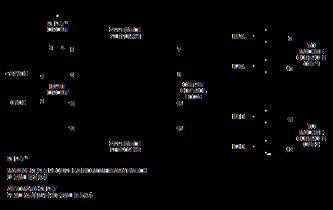

9 2-wire Safety Sensor Relay Dual Input with Dual Independent Safety Outputs


10 Solid State Safety Outputs Available Enclosures DIN RAIL 2.7 x2.5 x4.4 DIN RAIL 2.7 x3.2 x4.4 MEMA 4X WALL MOUNT 3.9 x3.9 x3.6 NEMA 7 & 9 Explosion Proof 4.6 x4.6 x4.5
PRSU/5 Safety Interface Controller
 PRSU/5 Safety Interface Controller Installation Instructions 1. INTRODUCTION Tapeswitch PRSU/5 control units are designed to be used with Tapeswitch pressure sensitive sensors to form a complete safety
Operating Instructions. For. Level Control Module. Model SSR 1000
 Operating Instructions For Level Control Module Model SSR 1000 SSR Operation Instructions Rev. 1 Jan 01 Page 1/7 1. Note Please read and take note of these operating instructions before unpacking and commissioning.
MSR Level Control Relay Module Operating Instructions for Level Control Relay Module Model: MSR
 Operating Instructions for Level Control Relay Module Model: MSR MSR Operation Instructions Rev. Apr 07 Page 1/8 1. Note Please read and take note of these operating instructions before unpacking and commissioning.
SafeC S to MSR127 Conversion
 Application Note SafeC S to MSR127 Conversion IMPORTANT: A risk assessment must be completed to assure that all tasks and hazards are considered and confirm that the example circuit will provide adequate
Installation, Testing, and Operating Procedures 30 AMP PORTABLE AND PERMANENT SERIES GFCI SINGLE and MULTIPHASE
 IMPORTANT! Please read all the information on this sheet. SAVE THESE INSTRUCTIONS! NOTICE BEFORE USING READ INSTRUCTIONS COMPLETELY. TO BE INSTALLED BY A QUALIFIED ELECTRICIAN IN ACCORDANCE WITH NATIONAL
For full product information, visit Use the SpeedSpec code or scan the QR Code for quick access to the specific web page.
 R Safety Monitoring Relays For full product information, visit www.sti.com. Use the SpeedSpec code or scan the QR Code for quick access to the specific web page. Dual-Channel Safety Monitoring Relay Power
CurrentWatch Current Sensors. EGF Series Ground Fault Sensors. Ground Fault Sensors with Solid-State or Mechanical Relay Outputs.
 CurrentWatch Current Sensors Ground Fault Sensors with Solid-State or Mechanical Relay s 1 Contents Overview.................... 1 Model Selection, Switches...... 2 Model Selection, Accessories... 3 Wiring
Control unit SG-EFS 104/4L. EN Operating instructions. Innovative by tradition. Version SG-EFS 104/4L AC/DC 24 V
 Innovative by tradition. Control unit SG-EFS 104/4L EN Operating instructions Version 2 1004128 SG-EFS 104/4L AC/DC 24 V Original instructions Mayser GmbH & Co. KG Örlinger Straße 1 3 89073 Ulm GERMANY
ZC Series Zone Monitoring Controllers
 ZC Series Zone Monitoring Controllers Installation Instructions MANUAL Reset Controllers Model Description Part Number ZC-1 1 Zone Controller 0421 ZC-2 2 Zone Controller 0422 ZC-3 3 Zone Controller 0423
Copyright 2011 Rockwell Automation, Inc. All rights reserved. Next Generation Guardmaster Safety Relay Platform Overview
 Next Generation Guardmaster Safety Relay Platform Overview RA Safety Relays MSR Minotaur Safety Relay MSR6 Rockwell Automation s first electromechanical safety relay series MSR100 2nd generation of electromechanical
Control unit SG-EFS 104/2W. EN Operating instructions. Innovative by tradition. Version SG-EFS 104/2W 24 V=/~
 Innovative by tradition. Control unit SG-EFS 104/2W EN Operating instructions Version 0.9 1005196 SG-EFS 104/2W 24 V=/~ Original instructions Mayser GmbH & Co. KG Örlinger Straße 1 3 89073 Ulm GERMANY
IO-PT4. Component identification. User safety and equipment protection guidelines. Unitronics Industrial Automation Systems 1
 IO-PT4 I/O Expansion Module 4 PT100 Inputs (-50 to 460 C) The IO-PT4 is an I/O expansion module that can be used in conjunction with specific Unitronics OPLC controllers. The module offers 4 PT100 inputs
BNS SERIES - COMPATIBLE SERIES AES SAFETY CONTROLLERS SELECTION CHART AVAILABLE STANDARD MODELS
 BNS SERIES - COMPATIBLE SERIES AES SAFETY CONTROLLERS SELECTION CHART AVAILABLE STANDARD MODELS Safety Controller Suitable for use with Coded-Magnet Sensor Part Numbers below BNS250... BNS33... BNS303...
Solid State Relays and Timers Family
 Solid State Relays and Timers Family Vehicle Control Modules Waytek Stock No. Volt Rating Amp Rating Notes Dual Input Relay Activating either Input A or Input B sets output. 75532 12 15 Dual inputs Latching
SIL 2/3 Relays for all applications, with or without Line & Load Diagnostics. Product presentation
 SIL 2/3 for all applications, with or without Line & Load Diagnostics Product presentation Safety Safety Functions Safety Functions can be basically divided in two main groups: ETS, Energize to Safety
Polymer Electric. Operating Instructions. Control Unit SG-EFS 1X4 ZK2/1 8k2. Version 3
 Operating Instructions Control Unit SG-EFS 1X4 ZK2/1 8k2 Version 3 1003100 SG-EFS 104 ZK2/1 8k2 24 V=/~ 7500354 SG-EFS 134 ZK2/1 8k2 230 V~ Original instructions GmbH & Co. KG Polymer Electric Örlinger
D5090S INSTRUCTION MANUAL. D A SIL 3 Relay Output Module for NE Load. DIN-Rail and Termination Board, Model D5090S
 D5090S INSTRUCTI MANUAL 4 A Relay Output Module for NE, DIN-Rail and Termination Board, Model D5090S D5090-4 A Relay Output Module for NE G.M. International ISM09-3 Characteristics General Description:
Introduction Circuit Protection
 Introduction Circuit Protection Weidmuller s DIN-rail mounted circuit breakers are available for use in applications where circuit protection must be able to distinguish between circuit overloads and short
Compact Coded Magnetic Safety Interlock Switch and Control Units
 C Conforms to EN292, EN60204-1, EN954-1, EN1088, EN60947-5-3, EN947-5-3, EN50081, EN50082, EN61000-6-2 UL and C-UL listed, TUV certified Description R US Compact Coded Magnetic Safety Interlock Switch
Magnetically Actuated Safety Interlock Switches
 Rev. 7.07 C US Conforms to EN1088, EN292, EN6020-1 CSA approved MA Series Magnetically Actuated Safety Interlock es Large selection choose from a large selection of contact configurations housed in plastic
ALTERNATING RELAYS & CONTROLLERS ARM Series
 ALTERNATING RELAYS & CONTROLLERS ARM Series Process Control Equipment for Hazardous Locations 7M26 UL913 INCLUDES INTRINSICALLY SAFE INPUTS Integrated Duplex Controller SOSO Operation (Sequence-on, Simultaneous-off)
ISO 9001 CERTIFIED. 607 NW 27th Ave Ocala, FL Phone: (352) or Fax: (352) SUITABLE FOR EXTERNAL DISTRIBUTION
 or Fax: (352) SUITABLE FOR EXTERNAL DISTRIBUTION") ISO 9001 CERTIFIED Phone: (352) 629-5020 or 800-533-3569 Fax: (352)-629-2902 ES-Key 12- Relay Board P/N 103190 and 103338 PAGE 1 of 13 1. REVISI LOG... 2 2. OVERVIEW... 3 2.1. PART NUMBERS... 3 2.2. MODULE
ISO 9001 CERTIFIED Phone: (352) 629-5020 or 800-533-3569 Fax: (352)-629-2902 ES-Key 12- Relay Board P/N 103190 and 103338 PAGE 1 of 13 1. REVISI LOG... 2 2. OVERVIEW... 3 2.1. PART NUMBERS... 3 2.2. MODULE
Quick Start Guide TS A
 Quick Start Guide TS 930 125-630A DANGER HAZARD OF ELECTRICAL SHOCK, EXPLOSION, OR ARC FLASH Read and understand this quick start guide before installing and operating the transfer switch The installer
high RESISTANCE STOPLIGHT Instruction Manual C-101EM
 stoplight high RESISTANCE GROUNDING SYSTEM STOPLIGHT Instruction Manual C-101EM high resistance grounding protection The StopLight system uses a unique indicator light system to provide visual detection
SMARTSCAN INFORMATION
 SMARTSCAN INFORMATION RY4 SERIES SAFETY RELAYS HANDBOOK Smartscan Ltd, Pywell Road, CORBY, NN17 5XJ, UK, Tel: +44 (0) 1536 401313, Fax: +44 (0) 1536 268954, Email: sales@smartscan.com, www.smartscan.co.uk
PGR-6101 MANUAL GROUND-FAULT & INSULATION MONITOR
 Tel: +1-800-832-3873 E-mail: techline@littelfuse.com www.littelfuse.com PGR-6101 MANUAL GROUND-FAULT & INSULATION MONITOR Revision 0-C-041918 Copyright 2018 by Littelfuse, Inc. All rights reserved. Document
Iso DIN. User Manual. 1 channel Earth Fault Monitoring
 Page 1 of 5 2017 03 20 User Manual Iso DIN Iso DIN User Manual 1 channel Earth Fault Monitoring Megacon AB Ranhammarsvägen 20 S 168 67 Bromma Sweden Tel: 08 402 42 50 sales@megacon.se www.megacon.se eee
D6030S - D6030D INSTRUCTION MANUAL. D SIL 3 Switch/Proximity Detector Repeater Relay Output. Models D6030S, D6030D
 D600S - D600D INSTRUCTI MANUAL SIL Switch/Proximity Detector Repeater Relay, DIN Rail, Models D600S, D600D D600 - SIL Switch/Proximity Detector Repeater Relay G.M. International ISM0- Characteristics General
Safe monitoring relays
 monitor for safe standstill monitoring Approvals Block diagram Unit features Positive-guided relay outputs: 2 safety contacts (N/O), instantaneous 1 auxiliary contact (N/C), instantaneous LED indicator
Latching, Sequence and Impulse Relays Application Data
 Latching, Sequence and Impulse Relays Application Data Energy Conservation Relays In many applications it is important for the customer to conserve electrical energy. One approach to energy conservation
Safety Contacts: AC models MA-1 thru 5, 10, 12, 13, 16 1 N/C MA-13, 16, 21 2 N/C DC models MA-12, 13, 14, 16 1 N/C MA-13, 15, 16, 20, 21 2 N/C
 r Safety Interlock Switches MA Series MA Magnetically Actuated Safety Interlock Switches Large selection choose from a large selection of contact configurations housed in plastic to satisfy most application
MAXIMA+ Series Rotary Level Indicator
 MAXIMA+ Series Rotary Level Indicator BinMaster: Division of Garner Industries 7201 N. 98th St., Lincoln, NE 68507 402-434-9102 email: info@binmaster.com www.binmaster.com OPERATING INSTRUCTIONS PLEASE
For full product information, visit Use the SpeedSpec code or scan the QR Code for quick access to the specific web page.
 R Safety Interlock Switches MA Series MA For full product information, visit www.sti.com. Use the SpeedSpec code or scan the QR Code for quick access to the specific web page. Magnetically Actuated Safety
SMART SHOT CONTROLLER FLUID USERS GUIDE
 SMART SHOT CONTROLLER FLUID USERS GUIDE Pg. 2 SMART SHOT CONTROLLER FEATURES 3 SMART SHOT CONTROLLER FEATURES 3 SMART SHOT CONTROLLER CONFIGURATIONS 4 FLOAT/SENSOR WIRING 5 TOP AND BOTTOM FLOAT/SENSOR
INSTRUCTION MANUAL. Universal AC Input Switching Power Supply 24 Vdc Output DIN-Rail Models PSD1000, PSD1000F PSD PSD1000F
 PSD1000 - PSD1000F INSTRUCTION MANUAL Universal AC Input Switching Power Supply 24 Vdc Output DIN-Rail Models PSD1000, PSD1000F PSD1000 - Universal AC Input Switching Power Supply 24 Vdc Output ISM0089-4
MSR178DP. Description. Features. Specifications
 MSR178DP Description The MSR178DP is a multi-function time-delay relay for use in safety circuits. It can be configured by the user to perform on-delay, offdelay or single-pulse modes. It is used for applications
Polymer Electric. Operating Instructions. Control Unit SG-RST 153. Version 0.3
 Operating Instructions Control Unit SGRST 153 Version 0.3 1004931 SGRST 153 Original instructions GmbH & Co. KG Örlinger Straße 1 3 89073 Ulm GERMANY Tel.: +49 731 20610 Fax: +49 731 2061222 EMail: info.ulm@mayser.com
GuardLogix: Safety Gate Application with SensaGuard Switch
 Safety Application Example GuardLogix: Safety Gate Application with SensaGuard Switch Safety Rating: PLe, Cat. 4 to EN ISO 13849.1 2008 Introduction...2 Important User Information...2 General Safety Information...3
MAXIMA + Series ROTARY LEVEL CONTROL
 Price $5.00 MAXIMA + Series ROTARY LEVEL CONTROL OPERATING INSTRUCTIONS PLEASE READ CAREFULLY Division of Garner Industries 7201 North 98th Street Lincoln, NE 68507-9741 (402) 434-9102 925-0268 Rev. A
INSTRUCTION MANUAL. SIL 3 Relay Output Module DIN-Rail Models D1092S-069, D1092D-069 D1092S D1092D-069
 D09S09 D09D09 INSTRUCTION MANUAL SIL Relay Output Module DINRail Models D09S09, D09D09 D0909 SIL Relay Output Module ISM00 SIL Applications For Safety Related System and SIL, SIL Applications according
CS7 Industrial Control Relays
 CS7 Industrial Control Relays Reliable, general purpose relays for heavy duty applications The base four pole CS7 relay can be expanded up to twelve poles with the addition of front and side mount auxiliaries
Operating Instructions. Power Supply & Latching Relay For Switches Model: RL manual_rl-6000_1016
 Operating Instructions Power Supply & Latching Relay For Switches Model: RL-6000 manual_rl-6000_1016 1. Contents 1. Contents...2 2. Note...3 3. Instrument Inspection...3 4. Regulation Use...3 5. Operating
EM-F-7G Safety Extension Module
 EM-F-7G Safety Extension Module One-channel control with four safety output channels Features Safety Extension Module provides additional safety outputs for a Primary Safety Device (for example, an E-stop
LPG STM 94442A User s Manual
 1 LPG STM 94442A User s Manual This Manual belongs to: Company: 3 Table of Contents Features....... 4 Hardware Installation...5 Monitor Mounting Dimensions.....7 Monitor Specifications...8 Sender Specifications.....9
E-STOP relays, safety gate monitors
 Safety relay for monitoring E-STOP pushbuttons, safety gates and light barriers. Approvals Unit features Positive-guided relay outputs: 7 safety contacts (N/O), instantaneous 2 auxiliary contacts (N/C),
GuardLogix: Dual Zone Gate Protection with E-stop and Trojan Interlock Switch
 Safety Application Example GuardLogix: Dual Zone Gate Protection with E-stop and Trojan Interlock Switch Safety Rating: PLd, Cat. 3 to EN ISO 13849.1 2008 Introduction... 2 Important User Information...
PSSU/A2 Control Unit Installation Instructions
 PSSU/ Unit Installation Instructions INTROUTION The PSSU/ control unit is designed to be used with Tapeswitch pressure sensitive sensors, such as ribbon switches, sensing edges, bumpers, and presence-sensing
PGR-4300 MANUAL GENERATOR GROUND-FAULT RELAY
 Tel: +1-800-832-3873 E-mail: techline@littelfuse.com www.littelfuse.com PGR-4300 MANUAL GENERATOR GROUND-FAULT RELAY REVISION 3-B-041318 Copyright 2018 by Littelfuse, Inc. All rights reserved. Document
Magnetically Actuated Safety Interlock Switches
 Conforms to EN10, EN292, EN020-1 CSA and BG approved Actual Size Magnetically Actuated Safety Interlock Switches Large selection choose from a large selection of contact configurations housed in plastic,
8000 Series: Installation Supplement R2-1-12
 8000 Series: Installation Supplement R2-1-12 Smartscan Incorporated, 33083 Eight Mile Road, Livonia MI 48152 Tel: (248) 477-2900 Fax: (248) 477-7453 Web: www.smartscaninc.com SMARTSCAN INCORPORATED Livonia,
Original operating instructions Safety relay with relay outputs with and without delay G1502S / / 2016
 Original operating instructions Safety relay with relay outputs with and without delay UK G50S 803638 / 00 0 / 06 Contents Preliminary note...4. Symbols used...4 Safety instructions...5 3 Items supplied...6
DUO-TOUCH Modules mm mm. AT-..M-2A Models (AT-FM-2A Module shown)
") Modules Two-Hand Control Modules, OTB Compatible Monitors a pair of mechanical push buttons or OTB optical touch buttons. Permits machine operation only when the operator has both hands on the controls.
Modules Two-Hand Control Modules, OTB Compatible Monitors a pair of mechanical push buttons or OTB optical touch buttons. Permits machine operation only when the operator has both hands on the controls.
Barriers. EB3N Discrete Input Barrier with Redundant Output
 EB3N Discrete Input Barrier with Redundant Output s Build a safety system in an explosive atmosphere. Key features: Safety Performance Performance level e Category 4 [Exia] II C Ensures safety and machine
Bul. 440R Guardmaster Safety Relays (DI, DIS, SI, CI, EM, and EMD) Selection Guide
 Selection Guide") Bul. 440R Guardmaster Safety Relays (DI, DIS, SI, CI, EM, and EMD) Selection Guide Description The new generation of Guardmaster Safety Relays addresses the broad scope of applications in the intricate
Bul. 440R Guardmaster Safety Relays (DI, DIS, SI, CI, EM, and EMD) Selection Guide Description The new generation of Guardmaster Safety Relays addresses the broad scope of applications in the intricate
Wiring Inside the card reader you will see a circuit board. The connections are as follows:
 Power Adaptor (12VDC, Max. Current: 1A) If you purchased the Cardlock Series power supply cut the head of the adaptor and strip the insulation. If your locking mechanism, electric strike or magnetic lock
RSTI-EP Slice I/O. Digital Output Module
 GFK-2959B December 2015 RSTI-EP Slice I/O Digital Output Modules EP-2214, EP-2614, EP-2634, EP-2218, EP-225F Relay Output Module Solid-state Relay Output Module EP-2814 Module Status LED Channel Status
MT400 MOTION CONTROLLER
 MT400 MOTION CONTROLLER INSTALLATION & TECHNICAL MANUAL 5/30/2012 417 Wards Corner Road Loveland, OH 45140 800.659.8250 FAX: 513.398.2536 www.maxitronic.com Table of Contents Page 3: Page 4: Page 5: Page
Differential Liquid/Gas Pressure Transmitter
 Installation Instruction Differential Liquid/Gas Pressure Transmitter Catalog Number(s) 1414-CPZ10FWFAA, 1414-IPZ10FWFAA Explosion Hazard WARNING Do not use in an explosive or hazardous environment, with
Original operating instructions Safety relay with relay outputs G1501S / / 2016
 Original operating instructions Safety relay with relay outputs G50S UK 8023637 / 00 02 / 206 Contents Preliminary note...4. Symbols used...4 2 Safety instructions...5 3 Items supplied...6 4 Functions
MAXIMA + Series ROTARY LEVEL CONTROL
 Price $5.00 MAXIMA + Series ROTARY LEVEL CONTROL OPERATING INSTRUCTIONS PLEASE READ CAREFULLY Division of Garner Industries 7201 North 98th Street Lincoln, NE 68507-9741 (402) 434-9102 925-0268 TABLE OF
Amplifiers, Counters, Timers & Controls
 Amplifiers, Counters, Timers & Controls Panel Meter 814 Counter/Timer/Rate Indicator 815-817 Speed Monitor 818-819 Signal Converter 820-822 Power Supplies/Amplifier 823-824 813 Panel Meter Panel Meter
AS-i Safety Relay Output Module with Diagnostic Slave
 AS-i Safety Relay Output Module with Diagnostic Slave User Manual...supports the requirements for AS-i Safety up to SIL3 Revision date: 2016-03-9 Subject to modifications without notice. Generally, this
READ AND FOLLOW ALL SAFETY INSTRUCTIONS! SAVE THESE INSTRUCTIONS AND DELIVER TO OWNER AFTER INSTALLATION IMPORTANT SAFETY INSTRUCTIONS
 LRC0 8X0A Relay Control Panel BACnet MS/TP Enabled INSTALLATI INSTRUCTIS READ AND FOLLOW ALL SAFETY INSTRUCTIS! SAVE THESE INSTRUCTIS AND DELIVER TO OWNER AFTER INSTALLATI IMPORTANT SAFETY INSTRUCTIS!
CM Series. Most Diverse and Flexible Line of Coded Magnetic Safety Interlock Switches and Controllers. Description. Safety Interlock Switches
 R Safety Interlock Switches CM Series CM For full product information, visit www.sti.com. Use the SpeedSPEC Code for quick access to the specific web page. Most Diverse and Flexible Line of Coded Magnetic
PGR-6100 MANUAL GROUND-FAULT & INSULATION MONITOR
 Tel: +1-800-832-3873 E-mail: techline@littelfuse.com www.littelfuse.com/pgr-6100 PGR-6100 MANUAL GROUND-FAULT & INSULATION MONITOR Revision 2-C-050818 Copyright 2018 Littelfuse All rights reserved. Document
EC07 EC63. Compatible actuators: ERL2 ESD2. How to order EC 07 B. Series. B Installation. method
 Controller EC07 EC63 Compatible actuators: ERL ESD Features Compact, light weight and thin (Body width 35mm) Can be set without manual Perfect installation compatibility with actuator PC software available
BETRIEBSANLEITUNG TECHNICAL INSTRUCTION INTERFACE PSE2-SC-02 (24 V AC/DC) Version 1.4
 Version 1.4") Safety regulations - The unit should be installed and operated by persons, who are familiar with these instructions and the current regulations for safety at work and accident prevention. Follow local
Safety regulations - The unit should be installed and operated by persons, who are familiar with these instructions and the current regulations for safety at work and accident prevention. Follow local
onlinecomponents.com
 FF-RE59292 Extension Module Instructions for use (pending) (pending) IMPROPER INTALLATION Consult with U and/or European safety agencies and their requirements when designing a machine control, interface
Installation / Setup Manual
 April, 2008 Cat Series 4 Entrance Expansion Module Installation / Setup Manual CATD4 Select Engineered Systems, Inc. Page 1 CAT Series Auxiliary 4 eader Module This page left intentionally blank Page 2
Application Technique. Safety Function: Safety Camera with E-stop
 Application Technique Safety Function: Safety Camera with E-stop Products: Guardmaster Dual-input Safety Relay, Guardmaster SC300 Safety Camera Safety Rating: PLd, Cat. 3 to EN ISO 13849-1: 2008 2 Safety
Mounting and System Description for SSZ-Safety-Switching-Rails
 Mounting and System Description for 1 Further SSZ Products: - Safety Bumpers - Safety Mats - Floor Switches - Protection of shelving alleys PSA/P - Protection of Fork-lift trucks PSA/S - Special devices
ReFlx 100 PLUS COLLISION AVOIDANCE SYSTEM
 100 PLUS COLLISION AVOIDANCE SYSTEM The 100 Plus collision avoidance system is intended for use with bridges and trolleys to prevent collisions or to limit the approach of adjacent bridges or trolleys.
PHASE MONITOR RELAYS Product Summary
 Product Summary Phase Monitor Relays provide protection against premature equipment failure caused by voltage faults on 3 Phase systems. All Macromatic Phase Monitor Relays are designed to be compatible
APPLICATION CONTROL GUIDELINES. IntelliROL Power Supply PN Revision Date: March 15, 2017
 APPLICATION CONTROL GUIDELINES IntelliROL Power Supply PN 1176718 Revision Date: March 15, 2017 Table of Contents List of Tables...3 TGW Safety Recommendation...4 Warnings and Safety Instructions...5 Introduction...6
INSTALLATION INSTRUCTIONS
 LIGHTING CONTROL PANELS 16 AND 24 RELAYS INSTALLATION INSTRUCTIONS INSTALLATION OVERVIEW The installation instructions contained in this document are provided as a guide for proper and reliable installation.
Component identification
 IO-ATC8 I/O Expansion Module 8 Analog/Thermocouple Inputs The IO-ATC8 is an I/O Expansion Module that can be used in conjunction with specific Unitronics OPLC controllers. The module offers 8 inputs that
CS8 Industrial Control Relays
 CS8 Industrial Control Relays Despite increasing complexity, control systems and installations must become increasingly compact. And the CS8 Miniature Relay System packs maximum performance into minimum
Bulletin 700-P, 700DC-P Industrial Relays
 Bulletin 700-P, 700DC-P Industrial Relays Bulletin 700 P Direct Drive Convertible Contact Cartridge Relays NEMA and IEC ratings 600V maximum AC/DC Accessories for field installation: contact cartridges,
Mounting and System Description for SSZ-Safety-Bumpers
 Mounting and System Description for 1 Further SSZ Products: - Safety Switching Rails - Safety Mats - Floor Switches - Protection of shelving alleys PSA/P - Protection of Fork-lift trucks PSA/S - Special
PI-EX-ME-2NAM/COC-120VAC
 PI-EX-ME-NAM/COC-0VAC Ex-i NAMUR Isolation Amplifier, With Intrinsically Safe Input and Relay Output, PDT, Two-Channel, 0 V AC Supply INTERFACE Data Sheet 0944_00_en PHOENIX CONTACT - 0/008 Description
Positive-guided relay outputs: 3 safety contacts (N/O), instantaneous. 1 auxiliary contact (N/C), instantaneous
, instantaneous. 1 auxiliary contact (N/C), instantaneous") Safety relay for monitoring E-STOP pushbuttons. Approvals Unit features Positive-guided relay outputs: 3 safety contacts (N/O), instantaneous 1 auxiliary contact (N/C), instantaneous Safe separation of
Safety relay for monitoring E-STOP pushbuttons. Approvals Unit features Positive-guided relay outputs: 3 safety contacts (N/O), instantaneous 1 auxiliary contact (N/C), instantaneous Safe separation of
PGR-3200 MANUAL INSULATION MONITOR
 Tel: +1-800-832-3873 E-mail: techline@littelfuse.com www.littelfuse.com PGR-3200 MANUAL INSULATION MONITOR REVISION 3-E-040918 Copyright 2018 by Littelfuse, Inc. All rights reserved. Document Number: PM-1025-EN
PSR-PC50. SIL 3 coupling relay for safety-related switch on. Data sheet. 1 Description
 SIL 3 coupling relay for safety-related switch on Data sheet 105818_en_01 PHOENIX CONTACT 2014-08-18 1 Description The PSR-PC50 SIL coupling relay can be used for power adaptation and electrical isolation
02/11/2015
 DIN Rail Mount 22.5 mm ETM2 Part number 84874023 Version ETM : Controls temperature of machines using built-in PTC probes Line break or probe short-circuit detection Version ETM2 / ETM22 : Fault latching
SMS 4 / SMS 5 safety mat Product information
 SMS 4 / SMS 5 safety mat Product information SMS 4 / SMS 5 safety mats Safety mats are used for the protection of man on machinery and plants with hazardous movements. Typical fields of application are,
29 $ Manual Motor Starters FREESHIPPING. MOTOR CONTROLS 25. Features: MMS-32H Frame. MMS-63H Frame.
 www.factorymation.com/motorcontrols MOTOR CONTROLS 25 Manual Motor Starters High interrupt capacity Din rail and surface mounting Lockable handle (OFF position) IP20 finger safe terminals Class 10 thermal
PI-EX-ME-2NAM/COC-24VDC
 Ex-i NAMUR Isolation Amplifier, With Intrinsically Safe Input and Relay Output, PDT, Two-Channel, 4 V DC Supply INTERFACE Data Sheet 0033_0_en PHOENIX CONTACT - /007 Description The PI-EX-ME-NAM/COC-4VDC
ADVANCED TECHNICAL MANUAL AAC1 SMALL SYSTEM CONTROL CONSOLE. Redefine your comfort zone.
 ADVANCED TECHNICAL MANUAL AAC1 SMALL SYSTEM CONTROL CONSOLE ATM ACC1 Table of Contents Safety Precautions... 3 Overview... 4 Specifications... 4 Installation... 5 Control Console Operation... 9 2 Advanced
SECTION 16 LED DIAGNOSTIC FEATURES: EXPANSION UNITS: SCR-31P-i. SCR-73-i. SEU-31-i. SCR-31-42TD-i. SEU-31TD-i
 SECTION 16 VIPER Safety Relays Type: SCR-i (with added diagnostics) SAFETY RELAY FUNCTION: IDEM s VIPER SCR-i range of Safety Relays have been designed in accordance with EN60204-1 for safety circuits
Using the AUX Port on the Conext XW+ to Connect to a Generator or the Grid
 Using the AUX Port on the Conext XW+ to Connect to a Generator or the Grid solar.schneider-electric.com 976-0324-01-01/A July 2015 Application Note EXCLUSION FOR DOCUMENTATION UNLESS SPECIFICALLY AGREED
Installation, Operation and Maintenance Manual
 Document 481200 VGD-100 Vari-Green Drive Installation, Operation and Maintenance Manual Please read and save these instructions for future reference. Read carefully before attempting to assemble, install,
Operating Instructions
 Innovative by tradition. Operating Instructions Control Unit SG-RSV 239 Version 1 1003986 SG-RSV 239/24 24 V= 1005372 SG-RSV 239/36 36 V= 1003271 SG-RSV 239 50-150 V= Mayser GmbH & Co. KG Örlinger Straße
E-STOP relays, safety gate monitors
 Safety relay for monitoring E-STOP pushbuttons and safety gates. Approvals Unit features Positive-guided relay outputs: 5 safety contacts (N/O), instantaneous 1 auxiliary contact (N/C), instantaneous Connection
Operating Instructions. Power Supply & Isolation Relay for Switches Model: RL manual_rl-5900_0215
 Operating Instructions Power Supply & Isolation Relay for Switches Model: RL-5900 manual_rl-5900_0215 1. Contents 1. Contents...2 2. Note...3 3. Instrument Inspection...3 4. Regulation Use...3 5. Operating
INTRINSICALLY SAFE INSTRUMENTATION FOR HAZARDOUS AREAS
 INTRINSICALLY SAFE INSTRUMENTATION FOR HAZARDOUS AREAS SHORT FORM 2002 SERIES D1000 Intrinsically Safe Galvanic Isolators SERIES D1000, for DIN Rail Mounting, provide the most simple and cost effective
Rotork Fairchild PAX1 Linear Actuator User s Manual
 Rotork Fairchild PAX1 Linear Actuator User s Manual Product Overview The PAX1 is a flexible low voltage DC powered linear actuator featuring a 5 mm maximum thrust rod stroke moving at speeds up to 0 mm/min
Installation Instructions 4291 and 4292 Keypads
 Installation Instructions 4291 and 4292 Keypads A6851J 02/11 Copyright 2011, Sargent Manufacturing Company, an ASSA ABLOY Group company. All rights reserved. Reproduction in whole or in part without the
SS2200 Remote Controller
 SS2200 Remote Controller General Purpose, DC Voltage General The SS2200 Remote Controller is a microprocessor-based programmable controller specifically designed to control single line and dual line centralized
9926 Series Branch Rated Circuit Breakers AC Version
 Branch Rated AC Version Hydraulic Magnetic Single pole and double pole versions 20/240 VAC, 50/60 Hz Up to 25A Just 3 mm wide Mounts on 35mm DIN-rail UL 489 listed, CSA C22.2 No. 5-02, CE VDE Ordering
Positive-guided relay outputs: 3 safety contacts (N/O), instantaneous. 1 auxiliary contact (N/C), instantaneous
, instantaneous. 1 auxiliary contact (N/C), instantaneous") Two-hand control unit for press controllers and safety circuits Approvals Unit features Positive-guided relay outputs: 3 safety contacts (N/O), instantaneous 1 auxiliary contact (N/C), instantaneous 1
Two-hand control unit for press controllers and safety circuits Approvals Unit features Positive-guided relay outputs: 3 safety contacts (N/O), instantaneous 1 auxiliary contact (N/C), instantaneous 1