Introduction The company 07 The control of buildings 09 The KNX standard 10 The advantages 12 The ekinex devices 15
|
|
|
- Bertram Garrett
- 6 years ago
- Views:
Transcription

1 TECHNICAL 016EN
2 is a brand
3 Introduction The company 07 The control of buildings 09 The KNX standard 10 The advantages 12 The ekinex devices 15 Wall-mounting devices 18 Rail-mounting devices Supervision 133 Tools 142 Technical section 146 General terms of sale 157 Index (codes) 159 Index (description) 160

4 4

5 We believe in technologies that make life simpler, producing devices that make everyday tasks simpler. Our scenario is the whole world: homes, offices, public buildings, schools, hospitals, industries. Our concept of home automation is supported and made possible by the KNX standard, which allows the automated and decentralized management of technological systems of any type and size. We exploit the possibilities offered by the KNX system to guarantee high quality standards in a project, that we called ekinex. Made in Italy The products of the ekinex line are developed and produced in Italy. Thanks to a qualified and competent team, SBS has created a product that embodies the essence of Made in Italy design, attention to detail, cutting-edge technology and innovation. Designed for a global market, the ekinex products are the expression of the new Italian tradition that combines attention to craftsmanship in the manufacture of the product and high levels of technology. ekinex promotes the idea of an Italian design that is not a mere aesthetic exercise, but includes, as basic elements, user friendliness, immediate understanding of the function and balanced and intelligent application of technology. 5

6 6 TECHNICAL016EN

7 07 Introduction 18 Wall-mounting devices 87 Rail-mounting devices Supervision 142 Tools 146 Technical section 157 General terms of sale 159 Index (codes) 160 Index (description) The Company Founded in 1994, SBS is an Italian company active at national and international level in the consumer electronics business Engaged for nearly two decades in this fi eld, SBS develops products and applications for mobile phones and informatics. The wide and innovative product range, which includes about 2,500 different items, is constantly updated in order to meet the needs of a constantly changing market. The Headquarters are based in Miasino (Novara) with the Sales, Administration and Design departements. The logistic center is located in Pettenasco (Novara). In the site of Vaprio d Agogna (Novara) are based the departements of R&D and Technical Support dedicated to the ekinex product line. ekinex is an initiative developed in 2012 thanks to a group of technical experts in automation and in particular of the KNX standard. After the development of a fi rst set of certifi ed products, in 2014 offi cially he published on its website for the global market, operation that allows you to connect with the many operators of the home and building automation, architects and interior designers. To date, ekinex is directly present in 70 countries around the world by exporting its know-how and typically Italian quality design. 7

8 8 TECHNICAL016EN

9 07 Introduction 18 Wall-mounting devices 87 Rail-mounting devices Supervision 142 Tools 146 Technical section 157 General terms of sale 159 Index (codes) 160 Index (description) The control of buildings ekinex is an intelligent system for controlling homes and buildings, developed in accordance with the open KNX standard. Having an ekinex system means to increase comfort and safety, reduce energy consumption and raise the long-term value of a building using products characterized by fi ne aesthetics and a great simplicity of use. Setting up an ekinex system is easy and accessible cost-wise: a signal network is arranged at project level, reaching all those areas where commands, sensors or loads to be system-controlled are expected. The arrangement, achieved by means of a simple signal cable, represents an authentic network for the exchange of information between ekinex devices. The scalability, typical of ekinex building control systems, even allows to start off with a basic equipment, both in terms of functions and devices, which may be extended at a later stage, depending on individual requirements, the location s infi ll and economic availability. The investment is quickly paid back, and is protected in time. Thanks to the native openness and interoperability of the KNX standard, the system can even integrate functions that may not be available within the ekinex range of products. 9
, developed and brought to the market in the early 90 s.")
10 TECHNICAL016EN The KNX standard Great developments in the fi eld of home and building automation were made possible especially thanks to an open, modular and interoperable standard like KNX. This innovative standard was born from the merging of three European systems (EIB, BatiBUS and EHS), developed and brought to the market in the early 90 s. The diffusion of the system was facilitated by an intense work of cooperation at normative level in the standard committee at European level. For this reason, too, KNX is a standard characterized by a total conformity with norm EN on electronic systems for the control of homes and buildings (HBES, Home and Building Electronic Systems). The twenty-year presence on the market of this standard offers the best guarantee in terms of reliability and consolidation of the technology used. The openness of the standard and that of the KNX Association, on the other hand, ensure availability of products in the long run and a constant development, both in terms of technology and offering of products, functions and applications. The vitality of KNX proposals is witnessed by the sustained expansion of the association, seeing the entry of manufacturers, coming from many different areas, and from the tens of thousands of technicians who chose it to specialize in the fi eld of building automation. Achievable savings with the adoption of the KNX system for Home & Building control: 40% over shutters control 50% over individual ambient control 60% over ambient lighting control 60% over ventilation control 10

11 07 Introduction 18 Wall-mounting devices 87 Rail-mounting devices Supervision 142 Tools 146 Technical section 157 General terms of sale 159 Index (codes) 160 Index (description) YEARS OF EXPERIENCE NATIONAL GROUPS CERTIFIED PRODUCTS % MARKET SHARE IN THE BUILDING CONTROL IN EUROPE INSTALLERS IN 139 COUNTRIES TRAINING CENTERS IN 59 COUNTRIES For customers, the variety and availability of KNX products has no comparison in other technological areas, and the system openness translates into the highest free choice, thereby avoiding the disadvantageous dependence of having to buy from a single supplier. Thanks to the modularity of the system, a project can be extended in time, starting with a basic confi guration and adding more functions later. The native interoperability of KNX products is fundamental to technicians, as it allows to design a system by always choosing the most suitable technical options, reducing compromise and ties caused by isolated systems which do not converse with one another. Moreover, the system offers new professional opportunities to designers and system integrators, making it possible to receive a consistent and high-level technical training and become certified KNX Partners. The KNX standard is entirely compliant with norm EN on HBES (Home and Building Electronic Systems) systems) 11

12 TECHNICAL016EN The advantages Design, realize and use a home & building control plant with the KNX system has many advantages. Designer Compliant, open, interoperable system Can be used in all types of buildings, from small residential to large service industry ones Devices, from over 300 manufacturers, communicating between each other in native mode Constant expansion of available functions and applications System design by means of standard software (ETS), manufacturer-independent Easy realization of commands, controls, supervisions and displays Wide availability of complex logic Interfacing towards numerous other systems, protocols and standards Simple logic connections between functions and devices Large choice of device parametrizing options based on single requirements Reduction of building s fire load Certified training, standardized and available worldwide 12
 for all manufactures High quality and reliability of products (consolidated system)")
13 07 Introduction 18 Wall-mounting devices 87 Rail-mounting devices Supervision 142 Tools 146 Technical section 157 General terms of sale 159 Index (codes) 160 Index (description) Installer Reduced device assembly and cabling times Unique, fast connection system (cable and bus terminal block) for all manufactures High quality and reliability of products (consolidated system) Configuration and service commissioning by means of standard, manufacturer-independent software (ETS) Speed and flexibility in the expansion and the modification of use Remote access for maintenance and diagnosis interventions Reduction of cables needed for command, control and distribution circuits Certified training, standardized and available worldwide Opportunities for professional advancements Access to the world of innovative systems User Large choice of products High comfort, great operation safety More information, verification of own consumption habits Coordinated working of all building systems Multifunctional deployment of several devices System scalability and modularity Easy upgrading, without needing interventions on cabling nor masonry works Independence from single manufacturer More efficient building energy class (as per EN 15232) Easy system adaptations in case of changing needs Time-protected investment (open system) Building increase in value 13
14 14 TECHNICAL016EN
15 07 Introduction 18 Wall-mounting devices 87 Rail-mounting devices Supervision 142 Tools 146 Technical section 157 General terms of sale 159 Index (codes) 160 Index (description) The ekinex devices The range of ekinex KNX devices includes system devices, devices dedicated to single application functions and accessories. System devices allow basic operation of the bus system, while the devices dedicated to single application functions are developed specifi cally to execute the command, control and/or monitoring the technical systems in the building, like lighting, heating or shading. They include switching, control and display units, sensors and actuators, etc. Each device is fitted internally with a communication module linking to the KNX bus. All devices are realized in multiple mounting versions (protruding or recessed walls, electric cabinets or panels on DIN rails as per EN 60715) in accordance with their destination of use and with the main installation modality. The KNX certifi cation guarantees the interoperability among the devices of different KNX manufacturers. The entire procedure is disciplined by the certifi cation system developed by the KNX Association and is based on conformity tests carried out by third-party laboratories. The tests verify that the devices support the KNX protocol and that any information is coded in accordance with KNX specifi cations The presence of a KNX trademark on ekinex devices is a guarantee for the customer: SBS respects the quality management system in accordance with ISO 9001; The devices are compliant with the european norm EN , concerning fundamental aspects like electromagnetic compatibility, electrical safety and environmental conditions of use; They comply with indications in volumes 3 and 6 of KNX specifications; They comply with KNX interoperability requirements concerningstandardized data type and functional blocks. 15
16 16
 159 Index")
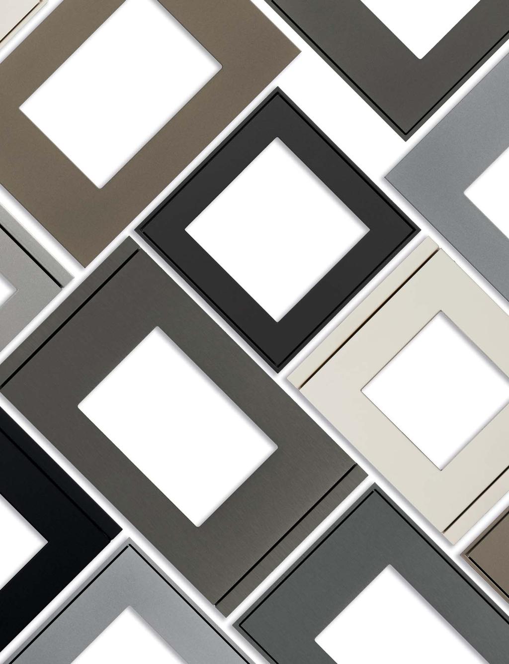
17 Introduction 07 Wall mounting devices FF series 18 Pushbuttons 23 Room thermostats 27 Touch&See displays 33 Sensors 39 Movement sensor 40 Presence sensor series 44 Pushbuttons 47 Room thermostats 51 Rockers 56 Plates and frames 63 Supports 71 Rail-mounting devices Supervision 133 Tools 142 Technical section 146 General terms of sale 157 Index (codes) 159 Index (description)


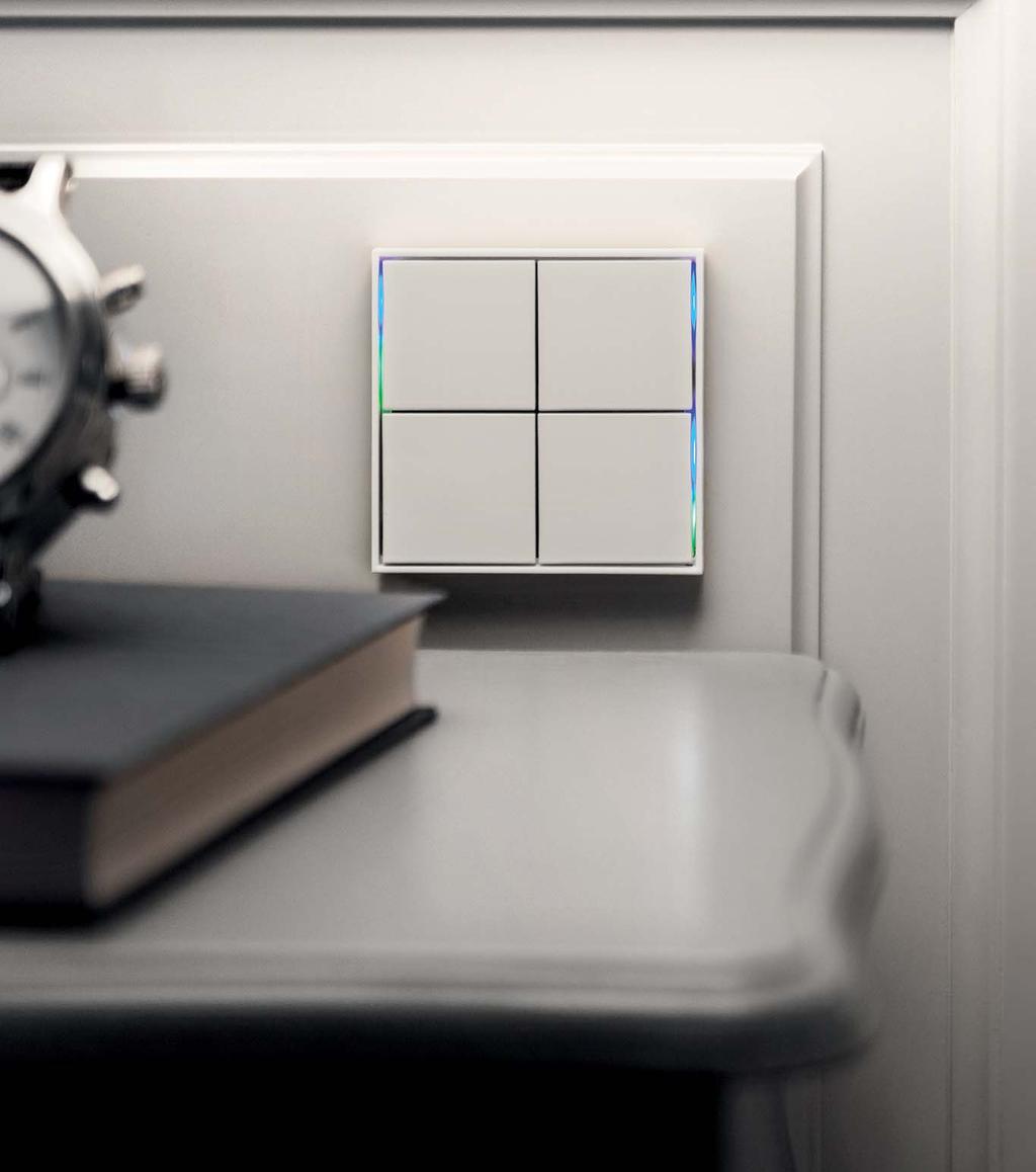
18 TECHNICAL016EN Wall-mounting devices FF SERIES FF series simple and linear. An essential form that suggests an idea of reliability and precision. A range of pushbuttons, touch-displays and plates which help to make yours the concept of home automation. Choose between form and flank frames or for NF model for a minimalist style even more pronounced. Simple shapes make the FF series adaptable to every environment and every lifestyle today. 18


 160 Index")


19 07 Introduction 18 Wall-mounting devices 87 Rail-mounting devices Supervision 142 Tools 146 Technical section 157 General terms of sale 159 Index (codes) 160 Index (description) FORM 86 x 86 x 8 mm 86 x 86 x 8 mm 86 x 86 x 8 mm 126 x 86 x 8 mm 60 x 60 mm 55 x 55 mm 45 x 45 mm 68 x 45 mm 86 x 86 x 8 mm 86 x 86 x 8 mm 86 x 86 x 8 mm 126 x 86 x 8 mm FLANK 94 x 86 x 8 mm 94 x 86 x 8 mm 94 x 86 x 8 mm 134 x 86 x 8 mm 60 x 60 mm 55 x 55 mm 45 x 45 mm 68 x 45 mm 94 x 86 x 8 mm 94 x 86 x 8 mm 94 x 86 x 8 mm 134 x 86 x 8 mm NF 80 x 80 x 8 mm 80 x 80 x 8 mm 80 x 80 x 8 mm 60 x 60 mm 55 x 55 mm 45 x 45 mm 68 x 45 mm 80 x 80 x 8 mm 80 x 80 x 8 mm 80 x 80 x 8 mm 120 x 80 x 8 mm 19
20 TECHNICAL016EN Wall-mounting devices EK-ED2-TP-... EK-EB2-TP-... EK-E12-TP-... EK-E12-TP-...-R Pushbutton 4-fold pushbutton Pushbutton 6-fold pushbutton and room thermostat and room thermostat and room thermostat FF series 71 series for rectangular FF series 71 series flush-mounting box 180 detection area (half-circular) detection area (circular) Detection range max. 10 m (mounting at 3 m) Installation height from 1 to 3 m passive infrared sensors (PIR) Adjustable sensitivity (10 levels) Confi gurable as master or slave device Measuring of natural and artifi cial light ON/OFF switching of single or groups of loads 4-fold (possibility of programming up to8 functions) - 6-fold (possibility of programming up to 12 functions) Seven main graphic pages rockers for controlling room thermostat functions fold (possibility of programming up to 4 functions) capacitive pushbuttons for controlling room thermostat functions inputs freely confi gurable (as digital or analogic) Dimming Control of shutters, venetian blinds, curtains, etc. Temperature sensor Brightness sensor Relative humidity sensor Room thermostat function 4 LED for each channel freely confi gurable (2 colour combination available) LC-Display with adjustable backlight ,5 TFT backlighted touch-display colours Scene recall function Programming pushbutton and LED on the frontal Connection to KNX bus Auxiliary power supply Wall-mounting on round or square fl ush-mounting box - Wall-mounting on rectangular 3-module fl ush-mounting box (Italian standard) - - Version for ceiling-mounting (different frames available) IP20 protection degree (installed) 20
21 07 Introduction 18 Wall-mounting devices 87 Rail-mounting devices Supervision 142 Tools 146 Technical section 157 General terms of sale 159 Index (codes) 160 Index (description) EK-EP2-TP-... EK-EQ2-TP-... EK-E72-TP-... EK-E72-TP-...-R EK-EC2-TP-... EK-EF2-TP-... EK-SM2-TP EK-DX2-TP Room thermostat FF series Room thermostat FF series with R.H. sensor Room thermostat 71 series Room thermostat 71 series for rectangular flush-mounting box Touch&See FF series Touch&See FF series with 2-fold pushbutton Movement sensor (wall-mounting) Presence sensor (ceiling-mounting)
 Round fl ush-mounting box not delivered by SBS - d) Square fl ush-mounting box not delivered by SBS - e) Rectangular fl ush-mounting box (3 modules) not delivered by SBS - f) Metal mounting")
22 TECHNICAL016EN e d g c n f m b l p i a q p o Pushbuttons FF series Description Code Page a) 4-fold pushbutton and room thermostat FF series EK-ED2-TP b) 6-fold pushbutton FF series EK-EB2-TP c) Round fl ush-mounting box not delivered by SBS - d) Square fl ush-mounting box not delivered by SBS - e) Rectangular fl ush-mounting box (3 modules) not delivered by SBS - f) Metal mounting support EK-SMQ g) Metal mounting support EK-SMR 71 Description Code Page i) Square frame fl ank series EK-FLQ l) Square frame form series EK-FOQ m) Rectangular frame fl ank series EK-FLR n) Rectangular frame form series EK-FOR o) Rectangular vertical rockers EK-TRV p) Square rockers EK-TQQ q) Rectangular horizontal rockers EK-TRO

 and 6-fold (EK-EB2- TP) pushbuttons; each one is fitted with a KNX communication module.")
 according to the Italian installation standard provided with fixing holes 83,5 mm apart.")
23 07 Introduction 18 Wall-mounting devices 87 Rail-mounting devices Supervision 142 Tools 146 Technical section 157 General terms of sale 159 Index (codes) 160 Index (description) Pushbuttons - FF series WALL-MOUNTING DEVICES Four or six channels, square or rectangular keys, with or without frame. Choose the combination that best suits your needs of style and features. The ekinex pushbuttons of FF series range and related accessories offer the possibility to realize several variations that will satisfy the most diverse needs. The base is represented by the 4-fold (EK-ED2-TP) and 6-fold (EK-EB2- TP) pushbuttons; each one is fitted with a KNX communication module. The 4-fold pushbutton (a) is suitable for mounting into a flush mounting box, either round (c) or square (d), provided with fixing holes 60 mm apart, while the 6-fold version (b) is also ideal for mounting into a rectangular wall mounting box 3 seater (e) according to the Italian installation standard provided with fixing holes 83,5 mm apart. Each device is supplied with its relative metal support (f, g) which, in case of necessity, can also be ordered separately. A terminal block complete the supply. The pushbuttons must be finished off with an operation surface (rockers) and a frame. The rockers are available in square (p) and rectangular (o, q) shapes, plastic material or aluminium, in several colour and finishing variations. The rockers can be personalized with symbols and text, so to make their function immediately understandable. Each pushbutton has integrated LEDs which can be programmed freely: as an example, as a status feedback or as an orientation light at night time. Two colour combinations are available for the LEDs: blue / green or red / white. The frames, square and rectangular (l), are available in two stylish alternatives (form and flank) and share the same choice of materials, colours and finishings as for rockers. The NF version of the 4-fold pushbutton is mounted without frame and is provided with a side profile in white or black colour. The pushbuttons simply get connected to the unique signal bus cable and do not require auxiliary power supply; the devices are supplied at SELV (Safety Extra Low Voltage) voltage, thus offering a much higher safety level than traditional commands. The configuration and commissioning is carried out by means of the ETS software. The related application programs can be downloaded from the website. 23

24 TECHNICAL016EN 4-fold pushbutton and room thermostat - FF series WALL-MOUNTING DEVICES Description The 4-fold pushbutton of ekinex FF series commands loads on/off switching, controls the dimming of lighting devices, controls motor drives for shutters or executes any other programmable command and control function. Thanks to the integrated temperature sensor, the pushbutton can work as a thermostat for a room or a zone. The LEDs can be chosen in the colour combinations blue / green or white / red. The device integrates a KNX bus communication module and is intended for mounting onto a wall mounting box; it is supplied by a SELV voltage directly from the KNX bus and does not require any auxiliary power supply. Main characteristics 4-fold (possibility to configure up to 8 independent functions) 4 freely programmable LEDs for each channel 2 colour combination available for the LEDs (blue/green or red/white) Integrated temperature and brightness sensor Room thermostat function Plastic casing Wall-mounting installation on round or square wall box Connection to bus line with KNX terminal block Frontal programming pushbutton and LED IP20 protection degree (installed) Weight 80 g (with mounting support) Technical data 30 Vdc power supply through KNX bus Current consumption from bus < 15 ma Delivery Delivery includes a terminal block for connection to the bus, a metal support for installation onto round or square mounting box (fixing holes 60 mm apart) and two pairs of fixing screws. The following accessories are available as finishings: square or rectangular rockers (page 56) square frame of form (page 64) or flank (page 65) series Dimensions [mm] Code LED colours Mounting Side profi le EK-ED2-TP blue / green with square frame of EK-ED2-TP-RW red / white form or fl ank series black EK-ED2-TP-BG-NF blue / green EK-ED2-TP-RW-NF EK-ED2-TP-BG-NFW EK-ED2-TP-RW-NFW red / white blue / green red / white without frame ( NF series) white Configuration and commissioning By means of ETS4 software (or later versions) Application program: APEKED2TP##.knxprod (## = version, downloadable from Documentation For more information, see the STEKED2TP_EN.pdf, technical sheet available for download from 24

25 07 Introduction 18 Wall-mounting devices 87 Rail-mounting devices Supervision 142 Tools 146 Technical section 157 General terms of sale 159 Index (codes) 160 Index (description) 6-fold pushbutton - FF series WALL-MOUNTING DEVICES Description The 6-fold pushbutton of ekinex FF series commands loads on/off switching, controls the dimming of lighting devices, controls motor drives for shutters or executes any other programmable command and control function. Thanks to the integrated temperature sensor, the pushbutton can send the room temperature value on the bus to other KNX devices. The LEDs can be chosen in the colour combinations blue / green or white / red. The device integrates a KNX bus communication module and is intended for mounting onto a wall mounting box; it is supplied by a SELV voltage directly from the KNX bus and does not require any auxiliary power supply. Main characteristics 6-fold (possibility to configure up to 12 independent functions) 4 freely programmable LEDs for each channel 2 colour combination available for the LEDs (blue/green or red/white) Integrated temperature and brightness sensor Plastic casing Wall-mounting installation on round, square or rectangular wall box Connection to bus line with KNX terminal block Rear programming pushbutton and LED IP20 protection degree (installed) Weight 75 g (with mounting support) Technical data 30 Vdc power supply through KNX bus Current consumption from bus < 15 ma Delivery Delivery includes a terminal block for connection to the bus, a metal support for installation onto round or square mounting box (fixing holes 60 mm apart) or rectangular mounting box (fixing holes 83,5 mm apart) and two pairs of fixing screws. The following accessories are available as finishings: square rockers (page 57) rectangular frame of form (page 64) or flank (page 65) series Dimensions [mm] Code LED colours Mounting EK-EB2-TP blue / green with rectangular frame EK-EB2-TP-RW red / white of form or fl ank series Configuration and commissioning By means of ETS4 software (or later versions) Application program: APEKEB2TP##.knxprod (## = version, downloadable from Documentation For more information, see the STEKEB2TP_EN.pdf, technical sheet available for download from 25
26 26 TECHNICAL016EN
 160 Index (description) Room thermostats - FF series WALL-MOUNTING DEVICES")


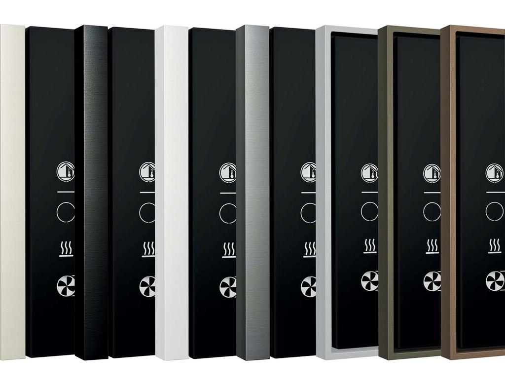
27 07 Introduction 18 Wall-mounting devices 87 Rail-mounting devices Supervision 142 Tools 146 Technical section 157 General terms of sale 159 Index (codes) 160 Index (description) Room thermostats - FF series WALL-MOUNTING DEVICES FORM 86 x 86 x 8 mm FLANK 94 x 86 x 8 mm NF 80 x 80 x 8 mm Aesthetics and functionality conjugated according to the ekinex style. The room temperature controls of the FF series contain the characteristics of a product with a strong technological footprint combined with a focus on aesthetic component. Available in form, fl ank and NF models, integrated LEDs and two custom keys, the ekinex room controllers are with their high performance able to meet the most different needs. 27
28 TECHNICAL016EN d c e g f a b Room thermostats FF series Description Code Page a) Room thermostat FF series EK-EP2-TP-... or EK-EQ2-TP b) Set 2 rockers for thermostat FF series EK-TSQ-EP c) Round fl ush-mounting box not delivered by SBS - d) Square fl ush-mounting box not delivered by SBS - e) Metal mounting support EK-SMQ 71 f) Square frame of fl ank series EK-FLQ g) Square frame of form series EK-FOQ

; each one integrates a KNX communication module.")
 which, in case of necessity, can also be ordered separately. A terminal block completes the delivery.")
29 07 Introduction 18 Wall-mounting devices 87 Rail-mounting devices Supervision 142 Tools 146 Technical section 157 General terms of sale 159 Index (codes) 160 Index (description) Room thermostats - FF series WALL-MOUNTING DEVICES Form, Flank, NF. Three different variations a room temperature control devicewith unique performance. The ekinex thermostats of FF series range and related accessories offer the possibility to realize several variations that will satisfy the most diverse needs. The base is represented by the thermostats EK-EP2-TP and EK-EQ2-TP (with relative humidity sensor); each one integrates a KNX communication module. The device (a) is suitable for mounting into a flush mounting box, either round (c) or square (d), provided with fixing holes 60 mm apart. Each thermostat is delivered with its relative metal support (e) which, in case of necessity, can also be ordered separately. A terminal block completes the delivery. The pushbuttons must be finished off with an operation surface (rockers) and a frame. The rockers are available in square shape, plastic material or aluminium, in several colour and finishing variations. A special set includes two customized rockers (b) with symbols for the thermostat functions. Each thermostat has integrated LEDs which can be programmed freely: as an example, as a status feedback or as an orientation light at night time. Two colour combinations are available for the LEDs: blue / green or red / white. The square frames are available in two stylish alternatives, form (g) and flank (f), and share the same choice of materials, colours and finishings as for rockers. The NF version of the thermostat is mounted without frame and is provided with a side profile in white or black colour. The thermostats simply get connected to the unique signal bus cable and do not require auxiliary power supply; the devices are powered at SELV (Safety Extra Low Voltage) voltage, thus offering a much higher safety level than traditional commands. The configuration and commissioning is carried out by means of the ETS software. The related application programs can be downloaded from the website. 29
30 TECHNICAL016EN Room thermostat - FF series WALL-MOUNTING DEVICES Description The ekinex room temperature controller of FF series regulates independentently the temperature of a room or a zone. In combination with one or more KNX actuators, the room temperature controller is able to control the heating and cooling emission of a series of terminal units for the thermal exchange (such as radiators, fan-coils, floor and ceiling radiant panels, etc.). The device is provided with a LC-display with adjustable backlight, sensors for temperature and brightness measuring and two freely configurable inputs. The LEDs can be chosen in the colour combinations blue / green or white / red. The device integrates a KNX bus communication module and is intended for mounting onto a wall mounting box; it is powered by a SELV voltage directly from the KNX bus and does not require any auxiliary power supply. Main characteristics LC-Display with adjustable backlight 2 rockers for controlling thermostat functions 4 freely programmable LEDs for each channel 2 colour combination available for the LEDs (blue/green or red/white) Integrated temperature and brightness sensor 2 freely configurable inputs Plastic casing Connection to bus line with KNX terminal block Frontal programming pushbutton and LED Wall-mounting installation on round or square wall box IP20 protection degree (installed) Weight 85 g (with mounting support) Technical data 30 Vdc power supply through KNX bus Current consumption from bus < 13 ma Delivery Delivery includes a terminal block for connection to the bus, a metal support for installation onto round or square mounting box (fixing holes 60 mm apart) and two pairs of fixing screws. The following accessories are available as finishings: set of two square rockers with symbols for room thermostat (page 58) square frame of form (page 64) or flank (page 65) series Dimensions [mm] Code LED colours Mounting Side profi le EK-EP2-TP blue / green with square frame of - EK-EP2-TP-RW red / white form or fl ank series Configuration and commissioning By means of ETS4 software (or later versions) Application program: APEKEP2TP##.knxprod (## = version, download from EK-EP2-TP-BG-NF EK-EP2-TP-RW-NF EK-EP2-TP-BG-NFW EK-EP2-TP-RW-NFW blue / green red / white blue / green red / white without frame ( NF series) black white Documentation For more information, see the STEKEP2TP_EN.pdf, technical sheet available for download from 30

31 07 Introduction 18 Wall-mounting devices 87 Rail-mounting devices Supervision 142 Tools 146 Technical section 157 General terms of sale 159 Index (codes) 160 Index (description) Room thermostat - FF series with relative humidity sensor WALL-MOUNTING DEVICES Description The ekinex room temperature controller of FF series regulates independentently the temperature of a room or a zone. In combination with one or more KNX actuators, the room temperature controller is able to control the heating and cooling emission of a series of terminal units for the thermal exchange (such as radiators, fan-coils, floor and ceiling radiant panels, etc.). The device is provided with a LC-display with adjustable backlight, sensors for temperature, relative humidity and brightness measuring and two freely configurable inputs. The LEDs can be chosen in the colour combinations blue / green or white / red. The device integrates a KNX bus communication module and is intended for mounting onto a wall mounting box; it is powered by a SELV voltage directly from the KNX bus and does not require any auxiliary power supply. Main characteristics LC-Display with adjustable backlight 2 rockers for controlling thermostat functions 4 freely programmable LEDs for each channel 2 colour combination available for the LEDs (blue/green or red/white) Integrated temperature, relative humidity and brightness sensor 2 freely configurable inputs Plastic casing Connection to bus line with KNX terminal block Frontal programming pushbutton and LED Wall-mounting installation on round or square wall box IP20 protection degree (installed) Weight 85 g (with mounting support) Technical data 30 Vdc power supply through KNX bus Current consumption from bus < 13 ma Delivery Delivery includes a terminal block for connection to the bus, a metal support for installation onto round or square mounting box (fixing holes 60 mm apart) and two pairs of fixing screws. The following accessories are available as finishings: set of two square rockers with symbols for room thermostat (page 58) square frame of form (page 64) or flank (page 65) series Dimensions [mm] Code LED colours Mounting Side profi le EK-EQ2-TP blue / green with square frame of - EK-EQ2-TP-RW red / white form or fl ank series Configuration and commissioning By means of ETS4 software (or later versions) Application program: APEKEQ2TP##.knxprod (## = version, download from EK-EQ2-TP-BG-NF EK-EQ2-TP-RW-NF EK-EQ2-TP-BG-NFW EK-EQ2-TP-RW-NFW blue / green red / white blue / green red / white without frame ( NF series) black white Documentation For more information, see the STEKEQ2TP_EN.pdf, technical sheet available for download from 31
32 32 TECHNICAL016EN

 160 Index")


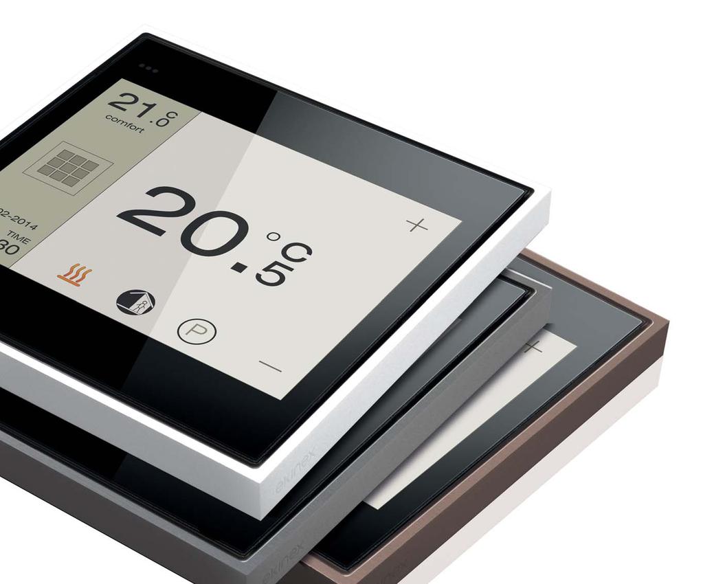
33 07 Introduction 18 Wall-mounting devices 87 Rail-mounting devices Supervision 142 Tools 146 Technical section 157 General terms of sale 159 Index (codes) 160 Index (description) Touch&See - FF series WALL-MOUNTING DEVICES Technology in a touch. When you want to touch the technology, see with your eyes your settings, know the weather or create the comfort you would like, trust Touch&See. The high resolution touch-display and the versatile and intuitive interface are thought to provide highest user comfort and uncompromising aesthetics. The transition from one function to the next one is via side-scrolling pages, from those you can access several submenus. You can also set the display brightness according to your own needs or it can be automatically adjusted according to the brightness. FORM 86 x 86 x 8 mm 126 x 86 x 8 mm CONTROLS THERMOSTAT FLANK 94 x 86 x 8 mm 134 x 86 x 8 mm METEO DATE NF 80 x 80 x 8 mm MUSIC SCENES 33
34 TECHNICAL016EN e d h c n g m l b f i a Touch&See FF series Description Code Page a) Touch&See display EK-EC2-TP b) Touch&See display with 2-fold pushbutton EK-EF2-TP c) Round fl ush-mounting box not delivered by SBS - d) Square fl ush-mounting box not delivered by SBS - e) Rectangular fl ush-mounting box (3 modules) not delivered by SBS - f) Square rockers EK-TSQ Description Code Page g) Metal mounting support EK-SMQ 71 h) Metal mounting support EK-SMR 71 i) Square frame fl ank series EK-FLQ l) Square frame form series EK-FOQ m) Rectangular frame fl ank series EK-FLR n) Rectangular frame form series EK-FOR


 is suitable for round (c) or square (d) wall mounting boxes with fixing holes 60 mm apart; the unit with the integrated 2-fold pushbutton (b) is also suitable for")
 which, in case of necessity, can also be obtained separately; the terminal blocks complete the supply.")
35 07 Introduction 18 Wall-mounting devices 87 Rail-mounting devices Supervision 142 Tools 146 Technical section 157 General terms of sale 159 Index (codes) 160 Index (description) Touch&See - FF series WALL-MOUNTING DEVICES Control and display unit with two-channel pushbutton. You will be amazed at all you can do The ekinex Touch&See display and control units allow to perform a great number of switching, control and display bus functions, utilizing the easiest and most compact devices, with their 3.5 touch-screen and their graphic pages having a clear meaning and immediate understanding. The base is represented by the control and display unit (EK-EC2-TP-...) and the control and display unit with integrated 2-fold pushbutton (EK-EF2-TP-...); each one integrates a KNX communication module. The control and display unit (a) is suitable for round (c) or square (d) wall mounting boxes with fixing holes 60 mm apart; the unit with the integrated 2-fold pushbutton (b) is also suitable for rectangular wall mounting boxes (e) provided with fixing holes 85 mm apart (3 seater according to the Italian installation standard). Each Touch&See unit is delivered with a metal mounting support (f, g) which, in case of necessity, can also be obtained separately; the terminal blocks complete the supply. The Touch&See unit needs to be finished with a frame (h); in the case of units with integrated 2-fold pushbuttons, it will also be necessary to provide it with two square rockers (f), available in plastic or aluminium and in several colours and finishings. The frames, either square (i, l) or rectangular (m, n), are available in two alternative styles (form and flank) and share the same choice of materials, colours and finishing. The rockers can be personalized with symbols and text, in order to make their function immediately understandable. Each channel of the 2-fold pushbutton has integrated LEDs which can be programmed freely: as an example, as a status feedback or as an orientation light at night time. Two colour combinations are available for the LEDs: blue / green or red / white. The NF version of the Touch&See EK-EC2-TP-... is mounted without frame and is provided with a side profile in white or black colour. The Touch&See units have to be connected to the signal bus cable and to an auxiliary power supply; the devices are powered at SELV (Safety Extra Low Voltage) voltage, thus offering a much higher safety level than traditional commands. The configuration and commissioning is carried out by means of the ETS software. The related application programs can be downloaded from the website. 35

36 TECHNICAL016EN Touch&See display WALL-MOUNTING DEVICES Description ekinex Touch&See is a KNX device for the switching, control and display of bus functions. By means of its touch-screen and its graphical user interface, it is possible to control KNX actuators in an easy and intuitive way, to display the information coming from the KNX actuators and sensors and to perform as a room thermostat for up to 4 independent zones, receiving the measured room temperature values from the bus. The device integrates a KNX bus communication module and is designed for wall mounting boxes; it is powered by a SELV voltage directly from the KNX bus and requires an auxiliary 30 Vdc power supply. Delivery Delivery includes a terminal block for connection to the bus, a terminal block for connection to the auxiliary power supply, a metal support for installation onto round or square mounting box (fixing holes 60 mm apart) and two pairs of fixing screws. The following accessories are available as finishings: square frame of form (page 64) or flank (page 65) series Technical data SELV power supply from KNX bus (communication) 30 Vdc auxiliary power supply (screen) Main characteristics 3,5 TFT back-lit touch display, 320 x 240 pixel resolution, 65,536 colours Seven main graphic pages Integrated brightness sensor Plastic casing Connection to bus line with KNX terminal block Connection to auxiliary power supply with yellow / white terminal block Programming pushbutton and LED on the rear Wall-mounting installation on round or square wall box IP20 protection degree (installed) Weight 110 g (with mounting support) Dimensions [mm] Code Mounting Side profi le EK-EC2-TP with square frame of form or fl ank series - Configuration and commissioning By means of ETS4 software (or later versions) Application program: APEKEC2TP##.knxprod (## = version, download from EK-EC2-TP-00-NF EK-EC2-TP-00-NFW without frame ( NF Serie) black white Documentation For more information, see the STEKEC2TP_EN.pdf, technical sheet available for download from 36

37 07 Introduction 18 Wall-mounting devices 87 Rail-mounting devices Supervision 142 Tools 146 Technical section 157 General terms of sale 159 Index (codes) 160 Index (description) Touch&See display with 2-fold pushbutton WALL-MOUNTING DEVICES Description ekinex Touch&See with 2-fold pushbutton is a KNX device for the switching, control and display of bus functions. By means of its touch-screen and the graphical user interface, it is possible to control KNX actuators in an easy and intuitive way, to display information coming from KNX actuators and sensors and to perform as a room thermostat for a maximum of 4 independent zones. One temperature value can be measured from the integrated sensor, while the other values can be received from the bus. The integrated 2-fold pushbutton allows the on/off command of loads, the dimming of lighting devices, the control of motor drives for shutters or the execution of any other programmable command and control function. The LEDs can be chosen in the colour combinations blue / green or white / red. The device integrates a KNX bus communication module and is designed or mounting onto a wall-mounting box; it is powered by SELV voltage directly from the KNX bus and requires an auxiliary 30 Vdc power supply. Delivery Delivery includes a terminal block for connection to the bus, a terminal block for connection to the auxiliary power supply, a metal support for installation onto round or square mounting box (fixing holes 60 mm apart) or rectangular mounting box (fixing holes 83,5 mm apart) and two pairs of fixing screws. The following accessories are available as finishings: square rockers (page 57) rectangular frame of form (page 64) or flank (page 65) series Main characteristics 3,5 TFT back-lit touch display, 320 x 240 pixel resolution, 65,536 colours Seven main graphic pages Dimensions [mm] Integrated temperature and brightness sensors 2-fold pushbutton (possibility to configure up to 4 independent functions) freely programmable LEDs for each channel 2 colour combination available for the LEDs (blue/green or red/white) Plastic casing Connection to bus line with KNX terminal block Connection to auxiliary power supply with yellow / white terminal block Programming pushbutton and LED on the rear Wall-mounting installation on round, square or rectangular wall box IP20 protection degree (installed) Weight 130 g (with mounting support) Technical data SELV power supply from KNX bus (communication) 30 Vdc auxiliary power supply (screen) Configuration and commissioning By means of ETS4 software (or later versions) Application program: APEKEF2TP##.knxprod (## = version, download from Code LED Mounting Documentation EK-EF2-TP EK-EF2-TP-RW blue / green red / white with rectangular frame of form or fl ank series For more information, see the STEKEF2TP_EN.pdf, technical sheet available for download from 37
38 TECHNICAL016EN h g f e d a b c Movement sensor Description Code Page a) Movement sensor with metallic support EK-SM2-TP 40 b) Cover with lens EK-CLM c) Square plate (55 x 55 mm window) EK-PQG Description Code Page f) Square frame of form Serie EK-FOQ g) Round fl ush-mounting box not delivered by SBS - h) Square fl ush-mounting box not delivered by SBS - d) Adapter (delivered with square plate) - - e) Square frame of fl ank Serie EK-FLQ

 which integrates a KNX communication module.")

39 07 Introduction 18 Wall-mounting devices 87 Rail-mounting devices Supervision 142 Tools 146 Technical section 157 General terms of sale 159 Index (codes) 160 Index (description) Sensors WALL-MOUNTING DEVICES Movement and presence sensors complete series of frames Form, Flank or 'NF version for aesthetic coordinated to ekinex pushbuttons. The ekinex movement sensor allows to control automatically bus functions, such as lighting or room heating and cooling. The base is represented by the device (EK-SM2-TP) which integrates a KNX communication module. The device (a), delivered with the corresponding metal mounting support and a terminal block for the bus connection, is suitable for round (g) or square (h) wall mounting boxes with fixing holes 60 mm apart. The movement sensor needs to be finished with a square plate with 55 x 55 mm window and a square frame of flank (e) or form (g) series, available in plastic or aluminium and in several colours and finishings. The device may be also installed with frame by separately ordering a square NF adapter provided with a side profile in white or black colour. The movement sensor has to be connected to the signal bus cable; the device is powered at SELV (Safety Extra Low Voltage) voltage, thus offering a much higher safety level than traditional sensors. The configuration and commissioning is carried out by means of the ETS software. The related application programs can be downloaded from the website. 39

; one further sensor measures room luminosity. The device can work in semi-automatic or automatic mode.")
 or flank (page 65) series square plate with")
 Ice white Intense black Silver EK-CLM-GAA EK-CLM-GAE EK-CLM-GAG Main characteristics 180 detection")
40 TECHNICAL016EN Movement sensor WALL-MOUNTING DEVICES Description The ekinex EK-SM2-TP movement sensor detects movement and presence of people in a semi-circular area. It is ideally used in corridors, transit areas, toilets, staircases, elevators and, in general, all areas having occasional transit. The device has one channel for lighting, and one channel for the control of HVAC devices. Movement and presence detection are operated by three PIR sensors (passive infra-red); one further sensor measures room luminosity. The device can work in semi-automatic or automatic mode. The device integrates a KNX bus communication module, is suitable for flushmounting boxes and is powered by a SELV voltage by means of the KNX bus. Technical data SELV voltage from KNX bus Power absorption 0,4 W The following accessories are available as finishings: square frame in form (page 64) or flank (page 65) series square plate with window 55 x 55 mm (EK-PQG, page 67) lens with modular cover 55 x 55 mm (see table below) Component [Pcs.] Dimensions [mm] Colour Code Lens with cover for sensor EK-SM2-TP 1 55 x 55 (lens protrusion 21) Ice white Intense black Silver EK-CLM-GAA EK-CLM-GAE EK-CLM-GAG Main characteristics 180 detection range (semi-circular) Max distance 10 m (mounted at 3 m height) Mounting height from 1 to 3 m 3 passive infra-red (PIR) sensors EK-CLM-GAA EK-CLM-GAE EK-CLM-GAG Adjustable sensitivity (10 levels) Master or slave configuration Dimensions [mm] Connection to bus line with KNX terminal block Frontal programming pushbutton and LED Wall-mounting installation on round or square wall box Metal support with screws for mounting on round or square mounting box (holes 60 mm apart) IP20 protection degree (installed) Weight 40 g Delivery Delivery includes a terminal block for connection to the bus, a metal support for installation onto round or square mounting box (fixing holes 60 mm apart) and two fixing screws. Configuration and commissioning By means of ETS3 software (or later versions) Application program: APEKSM2TP##.vd4 (## = version, download from Code EK-SM2-TP Package 1 pcs. Documentation For more information, see the STEKSM2TP_EN.pdf technical sheet available for download from 40

; one further sensor measures room luminosity. The device can work in semi-automatic or automatic mode.")
41 07 Introduction 18 Wall-mounting devices 87 Rail-mounting devices Supervision 142 Tools 146 Technical section 157 General terms of sale 159 Index (codes) 160 Index (description) Presence sensor WALL-MOUNTING DEVICES Description The ekinex EK-Dx2-TP presence sensor detects movement and the presence of people in a circular area. It is ideally used in open space, meeting rooms, halls, and, in general, all large rooms. The device has three separate channels for the control of lighting and one channel for HVAC device control. Movement and presence detection are operated by three PIR sensors (passive infra-red); one further sensor measures room luminosity. The device can work in semi-automatic or automatic mode. Constant luminosity regulation is performed by an ETS-configurable value or properly configured KNX pushbuttons. The device integrates a KNX bus communication module, is suitable for ceiling mounting and is powered by a SELV voltage by means of the KNX bus. Delivery Delivery includes a terminal block for connection to the bus, a plastic support for installation onto round or square mounting box (fixing holes 60 mm apart) and two fixing screws. Technical data SELV voltage from KNX bus Power absorption 0,4 W EK-DB2-TP EK-DC2-TP Main characteristics 360 Detection range (circular) 3 passive infra-red (PIR) sensors Adjustable sensitivity (10 levels) Measurement of natural and artificial light Master or slave configuration Connection to bus line with KNX terminal block Frontal programming pushbutton and LED Round or square frame Ceiling mounting installation Plastic support for mounting in round or square box (holes 60 mm apart) IP20 protection degree (installed) Weight 30 g EK-DD2-TP Dimensions [mm] EK-DE2-TP Max detection distance [m] Mounting height [m] Frame [Pcs.] Code round Ø 105 mm EK-DB2-TP square 86 x 86 mm EK-DC2-TP 1 round Ø 105 mm EK-DD2-TP square 86 x 86 mm EK-DE2-TP Configuration and commissioning By means of ETS3 software (or later versions) Application program: APEKSP2TP##.vd4 (## = version, download from Documentation For more information, see the STEKDX2TP_EN.pdf, technical sheet available for download from 41

42 42
 159 Index")
43 Introduction 07 Wall mounting devices FF series 18 Pushbuttons 23 Room thermostats 27 Touch&See displays 33 Sensors 39 Movement sensor 40 Presence sensor series 44 Pushbuttons 47 Room thermostats 51 Rockers 56 Plates and frames 63 Supports 71 Rail-mounting devices Supervision 133 Tools 142 Technical section 146 General terms of sale 157 Index (codes) 159 Index (description)


44 TECHNICAL016EN Wall-mounting devices 71 SERIES The clean and simple design that makes it distinct and compact unit. The pushbuttons, thermostats and junction points can be exchanged depending on your style and your needs. 71 series is designed for the projects to small budget, without compromising on high quality standards. 44


45 07 Introduction 18 Wall-mounting devices 87 Rail-mounting devices Supervision 142 Tools 146 Technical section 157 General terms of sale 159 Index (codes) 160 Index (description) FORM 55 x 55 mm 55 x 55 mm 60 x 60 mm 60 x 60 mm 86 x 86 x 8 mm 86 x 86 x 8 mm 156 x 86 x 9 mm 156 x 86 x 9 mm 55 x 55 mm 60 x 60 mm 60 x 60 mm 86 x 86 x 8 mm 86 x 86 x 8 mm 156 x 86 x 9 mm 125 x 86 x 8 mm FLANK 55 x 55 mm 55 x 55 mm 60 x 60 mm 60 x 60 mm 94 x 86 x 8 mm 94 x 86 x 8 mm 165 x 86 x 9 mm 165 x 86 x 9 mm 55 x 55 mm 60 x 60 mm 60 x 60 mm 94 x 86 x 8 mm 94 x 86 x 8 mm 165 x 86 x 9 mm 134 x 86 x 8 mm NF 55 x 55 mm 55 x 55 mm 60 x 60 mm 60 x 60 mm 80 x 80 x 8 mm 80 x 80 x 8 mm 151 x 86 x 9 mm 151 x 86 x 9 mm 55 x 55 mm 60 x 60 mm 60 x 60 mm 80 x 80 x 8 mm 80 x 80 x 8 mm 151 x 86 x 9 mm 134 x 86 x 8 mm 45
46 TECHNICAL016EN s r q n m o p l b i d a h g c f e Pushbuttons 71 series Description Code Page a) Pushbutton and room thermostat 71 series EK-E12-TP b) Pushbutton and room thermostat 71 series for rectangular 3-module box EK-E12-TP-...-R 49 c) Square plate (60 x 60 mm window) EK-PQS d) Rectangular plate (60 x 60 mm window) EK-PRS e) Square rocker (1) EK-T1Q f) Rectangular vertical rockers (2) EK-T2R g) Square rockers (4) EK-T4Q h) Rectangular horizontal rockers (4) EK-T4R i) Square frame fl ank series EK-FLQ Description Code Page l) Square frame form series EK-FOQ m) Rectangular frame fl ank series EK-FLR n) Rectangular frame form series EK-FOR o) Metal mounting support with adapter * 49 p) Metal mounting support EK-SMQ q) Round fl ush-mounting box not delivered by SBS - r) Square fl ush-mounting box not delivered by SBS - s) Rectangular fl ush-mounting box (3 modules) not delivered by SBS - *) Included in the delivery of the pushbutton 71 series for rectangular box (b) 46


 is also suitable for mounting into a rectangular wall mounting box (s) 3 seater according to the Italian installation standard provided with fixing holes 83,5 mm apart.")
, a plate with 60 x 60 mm window and a frame.")
47 07 Introduction 18 Wall-mounting devices 87 Rail-mounting devices Supervision 142 Tools 146 Technical section 157 General terms of sale 159 Index (codes) 160 Index (description) Pushbuttons - 71 series WALL-MOUNTING DEVICES 71 series: infinite number of combinations for a unique style. The series of 71 buttons are available in square or rectangular version with single or double window. The ekinex pushbuttons of 71 series range and related accessories offer the possibility to realize several variations that will satisfy the most diverse needs. The base is represented by the device which is fitted with a KNX communication module. The EK-E12-TP version (a) of the pushbutton is suitable for mounting into a flush mounting box, either round (q) or square (r), provided with fixing holes 60 mm apart, while the EK-E12-TP-...-R version (b) is also suitable for mounting into a rectangular wall mounting box (s) 3 seater according to the Italian installation standard provided with fixing holes 83,5 mm apart. Each pushbutton is delivered with its relative metal support (p, o) which, in case of necessity, can also be ordered separately. A plastic adapter and a terminal block complete the supply. The pushbuttons must be finished off with an operation surface (rockers), a plate with 60 x 60 mm window and a frame. The rockers are available in square (e, g) and rectangular (f, h) shapes of different modularities, in plastic material and in three different colours. Each pushbutton has integrated LEDs which can be programmed freely: as an example, as a status feedback or as an orientation light at night time. Two colour combinations are available for the LEDs: blue / green or red / white. The square (i, l) and rectangular (m, n) frames are available in two stylish alternatives (form and flank) and share the same choice of materials, colours and finishings as for rockers. The NF versions of the pushbutton are mounted without frame and are provided with a side profile in white or black colour. The pushbuttons simply get connected to the unique signal bus cable and do not require auxiliary power supply; the devices are powered at SELV (Safety Extra Low Voltage) voltage, thus offering a much higher safety level than traditional commands. The configuration and commissioning is carried out by means of the ETS software. The related application programs can be downloaded from the website. 47

48 TECHNICAL016EN 4-fold pushbutton and room thermostat - 71 series WALL-MOUNTING DEVICES Description The 4-fold pushbutton of ekinex 71 series commands loads on/off switching, controls the dimming of lighting devices, controls motor drives for shutters or executes any other programmable command and control function. Thanks to the integrated temperature sensor, the pushbutton can work as a thermostat for a room or a zone. The LED can be chosen in the colour combinations blue / green or white / red. The device integrates a KNX bus communication module and is intended for mounting onto a wall mounting box; it is powered by a SELV voltage directly from the KNX bus and does not require any auxiliary power supply. Main characteristics 4-fold (possibility to configure up to 8 independent functions) 4 freely programmable LED for each channel 2 colour combination available for the LED (blue / green or red / white) Room thermostat function Integrated temperature and brightness sensor Plastic casing Connection to bus line with KNX terminal block Frontal programming pushbutton and LED Wall-mounting installation on round or square wall box IP20 protection degree (installed) Weight 70 g (with mounting support) Delivery Delivery includes a terminal block for connection to the bus, a metal support for installation onto round or square mounting box (fixing holes 60 mm apart), a plastic adapter and two pairs of fixing screws. The following accessories are available as finishings: set of 1 square rocker, 2 vertical rectangular rockers, 4 square rockers or 4 horizontal rectangular rockers (page 59) square frame of form (page 64) or flank series (page 65) square plate with 60 x 60 mm window (page 67) Note Finishing a 71 series pushbutton with a square rocker with 60 x 60 mm modularity does not allow the use of the integrated brightness sensor. Dimensions [mm] 21 L 13 9 Technical data 30 Vdc power supply by KNX bus Current consumption from bus < 15 ma H 43 Mounting with frame: 81 x 77 (L x H) Mounting without frame ( NF): 80 x 80 (L x H) Code LED colours Mounting Side profi le EK-E12-TP blue / green with square frame of - EK-E12-TP-RW red / white form or fl ank series Configuration and commissioning By means of ETS4 software (or later versions) Application program: APEKE12TP##.knxprod (## = version, download from EK-E12-TP-BG-NF EK-E12-TP-RW-NF EK-E12-TP-BG-NFW EK-E12-TP-RW-NFW blue / green red / white blue / green red / white without frame ( NF series) black white Documentation For more information, see the STEKE12TP_EN.pdf, technical sheet available for download from 48

49 07 Introduction 18 Wall-mounting devices 87 Rail-mounting devices Supervision 142 Tools 146 Technical section 157 General terms of sale 159 Index (codes) 160 Index (description) 4-fold pushbutton and room thermostat for rectangular wall-box - 71 series WALL-MOUNTING DEVICES Description The 4-fold pushbutton of ekinex 71 series commands loads on/off switching, controls the dimming of lighting devices, controls motor drives for shutters or executes any other programmable command and control function. Thanks to the integrated temperature sensor, the pushbutton can work as a thermostat for a room or a zone. The LED can be chosen in the colour combinations blue / green or white / red. The device integrates a KNX bus communication module and is intended for mounting onto a wall mounting box; it is powered by a SELV voltage directly from the KNX bus and does not require any auxiliary power supply. Main characteristics 4-fold (possibility to configure up to 8 independent functions) 4 freely programmable LED for each channel 2 colour combination available for the LED (blue / green or red / white) Room thermostat function Integrated temperature and brightness sensor Plastic casing Connection to bus line with KNX terminal block Frontal programming pushbutton and LED Wall-mounting installation on round, square or rectangular wall box IP20 protection degree (installed) Weight 100 g (with mounting support) Delivery Delivery includes a terminal block for connection to the bus, a metal support for installation onto round or square mounting box (fixing holes 60 mm apart) or rectangular mounting box (fixing holes 83,5 mm apart), a plastic adapter and two pairs of fixing screws. The following accessories are available as finishings: set of 1 square rocker, 2 vertical rectangular rockers, 4 square rockers or 4 horizontal rectangular rockers (page 59) rectangular frame of form (page 64) or flank series (page 65) rectangular plate with 60 x 60 mm window (page 69) Note Finishing a 71 series pushbutton with a square rocker with 60 x 60 mm modularity does not allow the use of the integrated brightness sensor. Dimensions [mm] 21 L 12 9 Technical data 30 Vdc power supply by KNX bus Current consumption from bus < 15 ma H 43 Mounting with frame: 122 x 77 (L x H) Mounting without frame ( NF): 121 x 80 (L x H) Code LED colours Mounting Side profi le EK-E12-TP-R blue / green with rectangular frame of form or - EK-E12-TP-RW-R red / white fl ank series EK-E12-TP-BG-NF-R blue / green black EK-E12-TP-RW-NF-R red / white without frame EK-E12-TP-BG-NFW-R blue / green ( NF series) white EK-E12-TP-RW-NFW-R red / white Configuration and commissioning By means of ETS4 software (or later versions) Application program: APEKE12TP##.knxprod (## = version, download from Documentation For more information, see the STEKE12TP_EN.pdf, technical sheet available for download from 49

50 50 TECHNICAL016EN


51 07 Introduction 18 Wall-mounting devices 87 Rail-mounting devices Supervision 142 Tools 146 Technical section 157 General terms of sale 159 Index (codes) 160 Index (description) Room thermostats - 71 series WALL-MOUNTING DEVICES FORM 86 x 86 x 8 mm FLANK 94 x 86 x 8 mm NF 80 x 80 x 8 mm Create a positive atmosphere. The different operating modes of the 71 series room temperature control allow you to adapt the control to your needs, save energy and ensure your comfort. The numerous integrated functions ensure a comfortable environment in all seasons. The 71 room temperature control will make you want to come back home. 51
52 TECHNICAL016EN p o n m l f g i b h d a c Room thermostats 71 series Description Code Page a) Thermostat 71 series EK-E72-TP b) Thermostat 71 series for rectangular 3-module box EK-E12-TP-...-R 55 c) Square plate (60 x 60 mm window) EK-PQS d) Rectangular plate (60 x 60 mm window) EK-PRS f) Metal support with adapter * 55 g) Metal mounting support EK-SMQ h) Square frame fl ank series EK-FLQ Description Code Page i) Square frame form series EK-FOQ l) Rectangular frame fl ank series EK-FLR m) Rectangular frame form series EK-FOR n) Round fl ush-mounting box not delivered by SBS - o) Square fl ush-mounting box not delivered by SBS - p) Rectangular fl ush-mounting box (3 modules) not delivered by SBS - *) Included in the delivery of the thermostat 71 series for rectangular box (b) 52


 is also suitable for mounting into a rectangular wall mounting box (p) 3 modules according to the Italian installation standard provided with fixing holes 83,5 mm apart.")
 or rectangular (d) plate with 60 x 60 mm window and a square (h, i) or rectangular (l, m) frame.")

53 07 Introduction 18 Wall-mounting devices 87 Rail-mounting devices Supervision 142 Tools 146 Technical section 157 General terms of sale 159 Index (codes) 160 Index (description) Room thermostats - 71 series WALL-MOUNTING DEVICES Many different combinations, possibilities installation horizontally or vertically, 71 room temperature control meets all requirements. Yours too... The ekinex thermostats of 71 series range and related accessories offer the possibility to realize several variations that will satisfy the most diverse needs. The base is represented by the device which is fitted with a KNX communication module. The EK-E72-TP version (a) of the thermostat is suitable for mounting into a flush mounting box, either round (n) or square (o), provided with fixing holes 60 mm apart, while the EK-E72-TP-...-R version (b) is also suitable for mounting into a rectangular wall mounting box (p) 3 modules according to the Italian installation standard provided with fixing holes 83,5 mm apart. Each thermostat is delivered with its relative metal support (f, g) which, in case of necessity, can also be ordered separately. A plastic adapter and a terminal block complete the supply. Depending on the version, the thermostat must be finished off with a square (c) or rectangular (d) plate with 60 x 60 mm window and a square (h, i) or rectangular (l, m) frame. The frames are available in two stylish alternatives (form and flank). Plates and frames are in plastic material or aluminium, in several colour and finishing variations. The NF versions of the thermostats are mounted without frame and are provided with a side profile in white or black colour. The thermostats simply get connected to the unique signal bus cable and do not require auxiliary power supply; the devices are powered at SELV (Safety Extra Low Voltage) voltage, thus offering a much higher safety level than traditional commands. The configuration and commissioning is carried out by means of the ETS software. The related application programs can be downloaded from the website. 53
54 TECHNICAL016EN Room thermostat - 71 series WALL-MOUNTING DEVICES Descrizione The ekinex room temperature controller of 71 series regulates independentently the temperature of a room or a zone. In combination with one or more KNX actuators, the room temperature controller is able to control the heating and cooling emission of a series of terminal units for the thermal exchange (such as radiators, fan-coils, floor and ceiling radiant panels, etc.). The device is provided with a LC-display with adjustable backlight, and a sensor for temperature measuring. The device integrates a KNX bus communication module and is intended for mounting onto a wall mounting box; it is powered by a SELV voltage directly from the KNX bus and does not require any auxiliary power supply. Delivery Delivery includes a terminal block for connection to the bus, a metal support for installation onto round or square mounting box (fixing holes 60 mm apart), a plastic adapter, two fixing screws and two rubber screw covers. The following accessories are available as finishings: square frame of form (page 64) or flank series (page 65) square plate with 60 x 60 mm window (page 67) Main characteristics LC-Display with adjustable backlight 4 capacitive pushbuttons for controlling of the thermostat functions Integrated temperature sensor Plastic casing Connection to bus line with KNX terminal block Frontal programming pushbutton and LED Wall-mounting installation on round or square wall box IP20 protection degree (installed) Weight 90 g (with mounting support) Dimensions [mm] L Technical data 30 Vdc power supply by KNX bus Current consumption from bus < 13 ma H 43 Mounting with frame: 81 x 77 (L x H) Mounting without frame ( NF): 80 x 80 (L x H) Code Mounting Side profi le EK-E72-TP with square frame of form or fl ank series - EK-E72-TP-NF black without frame ( NF series) EK-E72-TP-NFW white Configuration and commissioning By means of ETS4 software (or later versions) Application program: APEKE72TP##.knxprod (## = version, download from Documentation For more information, see the STEKE72TP_EN.pdf, technical sheet available for download from 54
55 07 Introduction 18 Wall-mounting devices 87 Rail-mounting devices Supervision 142 Tools 146 Technical section 157 General terms of sale 159 Index (codes) 160 Index (description) Room thermostat for rectangular wall-box - 71 series WALL-MOUNTING DEVICES Descrizione The ekinex room temperature controller of 71 series regulates independentently the temperature of a room or a zone. In combination with one or more KNX actuators, the room temperature controller is able to control the heating and cooling emission of a series of terminal units for the thermal exchange (such as radiators, fan-coils, floor and ceiling radiant panels, etc.). The device is provided with a LC-display with adjustable backlight, and a sensor for temperature measuring. The device integrates a KNX bus communication module and is intended for mounting onto a wall mounting box; it is powered by a SELV voltage directly from the KNX bus and does not require any auxiliary power supply. Delivery Delivery includes a terminal block for connection to the bus, a metal support for installation onto rectangular mounting box (fixing holes 83,5 mm apart), a plastic adapter, two fixing screws and two rubber screw covers. The following accessories are available as finishings: rectangular frame of form (page 64) or flank series (page 65) rectangular plate with 60 x 60 mm window (page 69) Main characteristics LC-Display with adjustable backlight 4 capacitive pushbuttons for controlling of thermostat functions Integrated temperature sensor Plastic casing Connection to bus line with KNX terminal block Frontal programming pushbutton and LED Wall-mounting installation on round, square or rectangular wall box IP20 protection degree (installed) Weight 120 g (with mounting support) Dimensions [mm] L Technical data 30 Vdc power supply by KNX bus Current consumption from bus < 13 ma H 43 Mounting with frame: 122 x 77 (L x H) Mounting without frame ( NF): 121 x 80 (L x H) Code Mounting Side profi le EK-E72-TP-R with rectangular frame of form or fl ank series - EK-E72-TP-NF-R black without frame ( NF series) EK-E72-TP-NFW-R white Configuration and commissioning By means of ETS4 software (or later versions) Application program: APEKE72TP##.knxprod (## = version, download from Documentation For more information, see the STEKE72TP_EN.pdf, technical sheet available for download from 55
 or on either its left or right zones (horizontal rectangular")
 plus symbols and text (3 characters). For further information refer to page 80.")
56 TECHNICAL016EN Rockers for 4-fold pushbuttons - FF series WALL-MOUNTING DEVICES Description Rockers for use as operation surface for 4-fold pushbuttons of FF series. They can perform two independent functions by acting on either its upper or lower zones (square and vertical rectangular versions) or on either its left or right zones (horizontal rectangular versions). Rockers are available in three colours, in plastic material and are passive components. Order Base-codes must be completed by adding extensions for material, colour and finishing (3 chars) plus symbols and text (3 characters). For further information refer to page 80. Versions square with 40 x 40 mm modularity horizontal rectangular with 80 x 20 mm modularity vertical rectangular with 40 x 80 mm modularity Principali caratteristiche In plastic material or aluminium Snap-on mounting Customizable with symbols and text (from page 77) Delivery Delivery includes a tool for rockers removal. Dimensions [mm] 39,5 39, Code Modularity * L x H [mm] For use with ** Package EK-TQQ-... square 40 x 40 4 pcs. EK-TRV-... vertical rectangular 40 x 80 4-fold pushbutton FF series 2 pcs ,5 3 EK-TRO-... horizontal rectangular 80 x 20 4 pcs. 80 *) The modularity indicated also takes into account the distance between the rockers and between rockers and lightguides and, therefore, differs slightly from the actual size of the single rockers **) The actual functioning as pushbutton with 2 or 4 channels depends on the confi guration of the device parameters carried out with ETS 3 56

57 07 Introduction 18 Wall-mounting devices 87 Rail-mounting devices Supervision 142 Tools 146 Technical section 157 General terms of sale 159 Index (codes) 160 Index (description) Rockers for 6-fold pushbuttons and Touch&See - FF series WALL-MOUNTING DEVICES Description Rockers for use as operation surface for 6-fold pushbuttons and Touch&See with 2-fold pushbutton of FF series. They can perform two independent functions by pressing on either its upper or lower zones. Rockers are available in several colour and material variations and are passive components. Versions square with 40 x 40 mm modularity Delivery Delivery includes a tool for rockers removal. Order Base-codes (EK-TSQ) must be completed by adding extensions for material, colour and finishing (3 chars) plus symbols and text (3 characters). For further information refer to page 81. Main characteristics In plastic material or aluminium Snap-on mounting Customizable with symbols and text (from page 77) Dimensions [mm] 39,5 Code Modularity [mm] For use with Package. EK-TSQ-... square 40 x 40 6-fold pushbutton and Touch&See of FF series 4 pcs. 39,5 3 57

58 TECHNICAL016EN Set 2 rockers for room thermostats - FF series WALL-MOUNTING DEVICES Description Set rockers for use as operation surface for room thermostats of FF series. They can perform two independent functions by acting on either its upper or lower zones. Rockers are available in several colour and material variations and are passive components. Versions square with 40 x 40 mm modularity Delivery Delivery includes a tool for rockers removal. Order Base-codes (EK-TSQ-EP2) must be completed by adding extensions for material, colour and finishing (3 chars) For further information refer to page 81. Main characteristics In plastic material or aluminium Snap-on mounting Customized with symbols for room thermostat functions Dimensions [mm] 39,5 Code Modularity [mm] For use with Package. EK-TSQ-EP2-... square 40 x 40 room thermostats of FF series 2 pcs. 39,5 3 58

. Rockers are available in three colours, in plastic material and are passive components.")
59 07 Introduction 18 Wall-mounting devices 87 Rail-mounting devices Supervision 142 Tools 146 Technical section 157 General terms of sale 159 Index (codes) 160 Index (description) Rockers for pushbuttons - 71 series WALL-MOUNTING DEVICES Description Rockers for use as operation surface for pushbuttons of 71 series. They can perform two independent functions by acting on either its upper or lower zones (square and vertical rectangular versions) or on either its left or right zones (horizontal rectangular versions). Rockers are available in three colours, in plastic material and are passive components. Versions square with 60 x 60 mm or 30 x 30 mm modularity rectangular with 30 x 60 mm or 60 x 15 mm modularity Order Base-codes must be completed by adding extensions for colour (3 chars). For further information refer to page 81. Note Finishing off a 71 series pushbutton with a square rocker with 60 x 60 mm modularity does not allow the use of the integrated brightness sensor. Main characteristics In plastic material Snap-on mounting Dimensions [mm] 29,5 60 Code Modularity * L x H [mm] For use with ** Package 2,5 29 2,5 58 EK-T1Q-... square 60 x 60 1 pcs. EK-T2R-... vertical rectangular 30 x 60 2 pcs. pushbuttons of 71 series EK-T4Q-... square 30 x 30 4 pcs. EK-T4R-... horizontal rectangular 60 x 15 4 pcs. *) The modularity indicated also takes into account the distance between the rockers and between rockers and lightguides and, therefore, differs slightly from the actual size of the single rockers **) The actual functioning as pushbutton with 1, 2 or 4 channels depends on the confi guration of the device parameters carried out with ETS ,5 2,
60 60
61 07 Introduction 18 Wall-mounting devices 87 Rail-mounting devices Supervision 142 Tools 146 Technical section 157 General terms of sale 159 Index (codes) 160 Index (description) o n l m i f h b g e d a c for standard flush-mounting inserts Description Code Page a) 2 fl ush-mounting inserts with common support not delivered by SBS - b) 3 fl ush-mounting inserts with common support not delivered by SBS - c) Square plate EK-PQx-... (x = P, G, S) 67 d) Rectangular plate EK-PRx-... (x = P, G, S) 68 e) Square adapter EK-TAQ 67 f) Rectangular adapter EK-TAR 69 Description Code Page h) Square frame form series EK-FOQ i) Rectangular frame fl ank series EK-FLR l) Rectangular frame form series EK-FOR m) Round fl ush-mounting box not delivered by SBS - n) Square fl ush-mounting box not delivered by SBS - o) Rectangular 3-module fl ush-mounting box not delivered by SBS - g) Square frame fl ank series EK-FLQ
62 TECHNICAL016EN m l i h f g e b a c d Side-by-side installation 71 mm apart (71 series) Description Code Page a) Pushbutton 71 series EK-E12-TP b) Flush-mounting insert not delivered by SBS - c) Double plate for 71 Series EK-P2x-... (x = P, S o G) 70 d) Rockers for pushbutton 71 Series EK-Txx-... (xx = 1Q, 2R, 4Q, 4R) 59 e) Mounting support EK-SMQ Description Code Page g) Double adapter for mounting without frame EK-A h) Double frame of fl ank series with adapter EK-FL i) Double frame of form series with adapter EK-FO l) Double box for movable or plasterboard walls not delivered by SBS - m) Single modular boxes for bricks wall not delivered by SBS - f) Support for fl ush-mounting insert not delivered by SBS - 62
 for standard flush-mounting inserts WALL-MOUNTING DEVICES Evens out your control. Aesthetics is not a detail.")


 or flank (g, i).")
63 07 Introduction 18 Wall-mounting devices 87 Rail-mounting devices Supervision 142 Tools 146 Technical section 157 General terms of sale 159 Index (codes) 160 Index (description) for standard flush-mounting inserts WALL-MOUNTING DEVICES Evens out your control. Aesthetics is not a detail. Unifies your style with our universal plates and frames. They are compatible with the most common civil series on the market with the possibility of combinations between windows of 55 mm and 60 mm. Do not give up at the harmony of form. The ekinex accessories allow the creation of a system aesthetically coordinated with the bus devices of ekinex FF and 71 series. Flush-mounting inserts normally on the market, completed by their support, can be mounted on the appropriate adapters (e, f), which are finished with plates (a, b) and frames at choice of the series form (h, l) or flank (g, i). Adapters, plates and frames are available in two modularities, according to the flush-mounting box being used: square for round (m) or square (n) mounting box with fixing holes 60 mm apart; and rectangular for rectangular 3-module mounting box (o), according to the Italian installation standard with fixing holes 85 mm apart. Plates and frames are available in plastic material or aluminium, with several colour and finishing options. 63
64 TECHNICAL016EN Square frame - form series WALL-MOUNTING DEVICES Description Square frame of form series for finishing ekinex devices of FF and 71 series. Available in several colours and materials. Order Base-codes (EK-FOQ) must be completed by adding extensions for material, colour and finishing (3 chars) For further information refer to pages 82. Main characteristics In plastic material or aluminium Snap-on mounting Dimensions [mm] 86 8 Code Dimensions L x H x P [mm] For use with Package EK-FOQ x 86 x 8 devices of FF and 71 series 1 pcs. 86 Rectangular frame - form series WALL-MOUNTING DEVICES Description Rectangular frame of form series for finishing ekinex devices of FF and 71 series. Available in several colours and materials. Order Base-codes (EK-FOR) must be completed by adding extensions for material, colour and finishing (3 chars) For further information refer to pages 82. Main characteristics In plastic material or aluminium Snap-on mounting Dimensions [mm] Code Dimensions L x H x P [mm] For use with Package EK-FOR x 86 x 8 devices of FF and 71 series 1 pcs
65 07 Introduction 18 Wall-mounting devices 87 Rail-mounting devices Supervision 142 Tools 146 Technical section 157 General terms of sale 159 Index (codes) 160 Index (description) Square frame - flank series WALL-MOUNTING DEVICES Description Square frame of flank series for finishing ekinex devices of FF and 71 series. Available in several colours and materials. Order Base-codes (EK-FLQ) must be completed by adding extensions for material, colour and finishing (3 chars) For further information refer to page 83. Main characteristics In plastic material or aluminium Snap-on mounting Dimensions [mm] 94 8 Code Dimensions L x H x P [mm] For use with Package 80 EK-FLQ x 80 x 8 devices of FF and 71 series 1 pcs. Rectangular frame - flank series WALL-MOUNTING DEVICES Description Rectangular frame of flank series for finishing ekinex devices of FF and 71 series. Available in several colours and materials. Order Base-codes (EK-FLR) must be completed by adding extensions for material, colour and finishing (3 chars) For further information refer to pages 83. Main characteristics In plastic material or aluminium Snap-on mounting Dimensions [mm] Code Dimensions L x H x P [mm] For use with Package EK-FLR x 80 x 8 devices of FF and 71 series 1 pcs
66 TECHNICAL016EN Double frame - form series WALL-MOUNTING DEVICES Description Double frame of form series for finishing ekinex devices of 71 series. Available in several colours and materials. Order Base-codes (EK-FO2) must be completed by adding extensions for material, colour and finishing (3 chars) For further information refer to page 83. Main characteristics In plastic material or aluminium Dimensions [mm] Delivery Delivery includes a plastic adapter. 86 Code Dimensions L x H x P [mm] For use with Package EK-FO x 86 x 8 devices of 71 series 1 pcs. Double frame - flank series WALL-MOUNTING DEVICES Description Double frame of flank series for finishing ekinex devices of 71 series. Available in several colours and materials. Main characteristics In plastic material or aluminium Delivery Delivery includes a plastic adapter. Order Base-codes (EK-FL2) must be completed by adding extensions for material, colour and finishing (3 chars) For further information refer to page 83. Code Dimensions L x H x P [mm] For use with Package EK-FL x 80 x 8 devices of 71 series 1 pcs. Dimensions [mm]
67 07 Introduction 18 Wall-mounting devices 87 Rail-mounting devices Supervision 142 Tools 146 Technical section 157 General terms of sale 159 Index (codes) 160 Index (description) Square plate WALL-MOUNTING DEVICES Description Square plate for finishing ekinex devices of 71 series or market-standard flushmounted inserts. Available in several colours and materials. To be used in combination with a square frame of the form or flank series. The plate can be also mounted without frame in combination with an adapter of the NF series. Main characteristics In plastic material or aluminium Central window in three dimensions Snap-on mounting Delivery Delivery of each square plate includes an adapter (EK-TAQ) for mounting with a form or flank frame. Order Base-codes must be completed by adding extensions for material, colour and finishing (3 chars). For further information refer to page 84. Dimensions [mm] 80 3 Code Window L x H [mm] For use with * Package EK-PQP x 45 standard fl ush-mounted inserts EK-PQG x 55 1 pcs. 80 H L EK-PQS x 60 devices of 71 series *) In case of mounting without frame, the adapter included in the delivery of the plate is not used. It is replaced by an adapter for the NF series (to be ordered separately, see below) Adapter for square plate WALL-MOUNTING DEVICES Description Adapter for mounting of a square plate. Code For use with Side profi le Package EK-TAQ square plate with a form or fl ank frame - 10 pcs. Main characteristics Plastic material Side profile in black or white colour (only NF version) Mounting onto round or square mounting box with fixing holes 60 mm apart EK-TAQ-1-NF EK-TAQ-1-NFW EK-TAQ-5-NF EK-TAQ-5-NFW square plate without frame ( NF series) black white black white 1 pcs. 5 pcs. 67

68 TECHNICAL016EN Rectangular plate WALL-MOUNTING DEVICES Description Rectangular plate for finishing market-standard flush-mounted inserts. Available in several colours and materials. To be used in combination with a rectangular frame of the form or flank series. The plate can be also mounted without frame in combination with an adapter of the NF series. Main characteristics In plastic material or aluminium Central window in two dimensions Snap-on mounting Delivery Delivery of each rectangular plate includes an adapter (EK-TAR) for mounting with a form or flank frame. Order Base-codes must be completed by adding extensions for material, colour and finishing (3 chars). For further information refer to pages Dimensions [mm] Code Window L x H [mm] For use with * Package EK-PRP x 44 standard fl ush-mounted inserts 1 pcs. EK-PRG x H L *) In case of mounting without frame, the adapter included in the delivery of the plate is not used. It is replaced by an adapter for the NF series (to be ordered separately, see page 69) 68


69 07 Introduction 18 Wall-mounting devices 87 Rail-mounting devices Supervision 142 Tools 146 Technical section 157 General terms of sale 159 Index (codes) 160 Index (description) Rectangular plate for devices of 71 series WALL-MOUNTING DEVICES Description Rectangular plate for finishing ekinex devices of the 71 series to be installaed onto a rectangular mounting box with fixing holes 83,5 mm apart. Available in several colours and materials. To be used in combination with a rectangular frame of the form or flank series. The plate can be also mounted without frame in combination with an adapter of the NF series. Main characteristics In plastic material or aluminium 60 x 60 mm central window Snap-on mounting Order Base-codes must be completed by adding extensions for material, colour and finishing (3 chars). For further information refer to pages Note The metal support and the plastic adapter for mounting with a form or flank frame are included in the delivery of the ekinex device of 71 series. Dimensions [mm] Code Window L x H [mm] For use with * Package EK-PRS x 60 devices of 71 series 1 pcs. 80 H L *) In case of mounting without frame, the adapter included in the delivery of the device of 71 series is not used. It is replaced by an adapter for the NF series (to be ordered separately, see below) Adapter for rectangular plate WALL-MOUNTING DEVICES Description Adapter for mounting of a rectangular plate. Main characteristics Plastic material Side profile in black or white colour (only NF version) Mounting onto round or square mounting box with fixing holes 60 mm apart or onto rectangular mounting box with fixing holes 83,5 mm apart Code For use with Side profi le Package EK-TAR rectangular plate and form or fl ank frame - 10 pcs. EK-TAR-1-NF black 1 pcs. EK-TAR-1-NFW white rectangular plate without frame ( NF series) EK-TAR-5-NF black 5 pcs. EK-TAR-5-NFW white 69

70 TECHNICAL016EN Double plate - 71 series WALL-MOUNTING DEVICES Description Double plate for finishing standard flush-mounting inserts and/or ekinex devices of 71 series. Available in several colours and materials. To be used in combination with a double frame of the form or flank series. The plate can be also mounted without frame in combination with an adapter of the NF series. Main characteristics In plastic material or aluminium 3 combinations of windows sizes Snap-on mounting Order Base-codes must be completed by adding extensions for material, colour and finishing (3 chars). For further information refer to page 85. Note The adapter for mounting with double frame of form or flank series is included in the delivery of the frame (page 66). Dimensions [mm] Code Windows L x H [mm] For use with * Package EK-P2P x 55 (2) two devices installed 71 mm apart EK-P2G x 55 (1), 60 x 60 (1) (bus devices of 71 series 1 pcs. and/or fl ush-mounting inserts) EK-P2S x 60 (2) 80 H L H L *) In case of mounting without frame is used an adapter for NF series (to be ordered separately, see below) Adapter for mounting without frame - NF series WALL-MOUNTING DEVICES Description Adapter for mounting of a double plate without frame ( NF series). Code For use with Side profi le Package Main characteristics In plastic material Side profile in black or white colour For mounting onto round modular flush-mounting boxes (71 mm apart) EK-A71-1-NF EK-A71-1-NFW EK-A71-5-NF EK-A71-5-NFW double plate of 71 series without frame ( NF series) black white black white 1 pcs. 5 pcs. 70

71 07 Introduction 18 Wall-mounting devices 87 Rail-mounting devices Supervision 142 Tools 146 Technical section 157 General terms of sale 159 Index (codes) 160 Index (description) Square mounting support WALL-MOUNTING DEVICES Description Square metallic support for mounting ekinex devices of FF or 71 series onto round or square mounting boxes with fixing holes 60 mm apart. Fixing screws are provided. Dimensions [mm] 70 4, Note A mounting support is delivered with each ekinex device of FF and 71 series Code Dimensions L x H x P [mm] For use with Package EK-SMQ 72 x 70 x 5 thermostats and Touch&See FF series 5 pcs. EK-SMQ x 70 x 4,5 devices of 71 series and 4-fold pushbutton of FF series 5 pcs. Rectangular mounting support WALL-MOUNTING DEVICES Description Rectangular metallic support for mounting ekinex devices of FF or 71 series onto round or square mounting boxes with fixing holes 60 mm apart or onto rectangular, 3-seater mounting box with fixing holes 85 mm apart. Fixing screws are provided. Dimensions [mm] 93,5 4,5 Note A mounting support is delivered with each ekinex device of FF and 71 series Code Dimensions L x H x P [mm] For use with Package EK-SMR 110 x 68 x 5 6-fold pushbutton and Touch&See with 2-fold pushbutton of FF series EK-SMR-71 93,5 x 70 x 4,5 devices of 71 series 5 pcs
.")
![Dimensions [mm] 153 34 86 34 67 4 60 4 Code Frames For use with Package EK-DFO form 2 devices of FF series completed with square form frames 5 pcs.](/docs-images/79/80204004/images/72-1.jpg "Template for side-by-side mounting of FF series with flank frames WALL-MOUNTING DEVICES Description Template for horizontal or vertical double-mounting of two ekinex devices with square frame of the")
72 TECHNICAL016EN Template for side-by-side mounting of FF series with form frames WALL-MOUNTING DEVICES Description Template for horizontal or vertical double-mounting of two ekinex devices with square frame of the form series. Made of zinc-plated metal sheet, 1 mm thick. Employ depends on wall type (brick or panels). Dimensions [mm] Code Frames For use with Package EK-DFO form 2 devices of FF series completed with square form frames 5 pcs. Template for side-by-side mounting of FF series with flank frames WALL-MOUNTING DEVICES Description Template for horizontal or vertical double-mounting of two ekinex devices with square frame of the flank series. Made of zinc-plated metal sheet, 1 mm thick. Employ depends on wall type (brick or panels). Dimensions [mm] Code Frames For use with Package EK-DFL fl ank 2 devices of FF series completed with square fl ank frames 5 pcs

73 07 Introduction 18 Wall-mounting devices 87 Rail-mounting devices Supervision 142 Tools 146 Technical section 157 General terms of sale 159 Index (codes) 160 Index (description) Protection for 4-fold pushbutton - FF series WALL-MOUNTING DEVICES Description Transparent construction-site protection made of thermoformed plastic material for ekinex 4-fold pushbuttons of FF series. Using the protection avoids device soiling or contamination, e.g. during wall painting. Two relieves in correspondence with each rocker position allow pushbutton operation while protection is mounted. Dimensions [mm] Code For use with Package EK-PPQ-FF 4-fold pushbuttons of FF series 10 pcs. Protection for pushbutton - 71 series WALL-MOUNTING DEVICES Description Transparent construction-site protection made of thermoformed plastic material for ekinex Touch&See of FF series. Using the protection avoids device soiling or contamination, e.g. during wall painting. Dimensions [mm] 82 7 Nota A protection is delivered with each Touch&See of FF series. 78 Code For use with Package EK-PTQ-71 pushbuttons of 71 series 10 pcs. 73
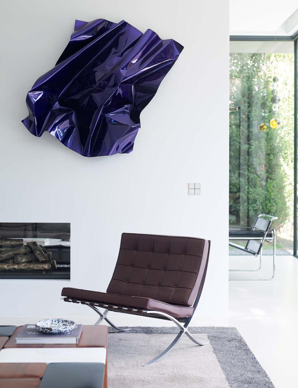
74 74
 Colour solutions - FF series ROCKERS, FRAMES AND PLATES WHITE PLASTIC BLACK PLASTIC GAA Ice white GAB * Ice white Soft-touch finishing GAC Fire white * GAD * Fire")

75 07 Introduction 18 Wall-mounting devices 87 Rail-mounting devices Supervision 142 Tools 146 Technical section 157 General terms of sale 159 Index (codes) 160 Index (description) Colour solutions - FF series ROCKERS, FRAMES AND PLATES WHITE PLASTIC BLACK PLASTIC GAA Ice white GAB * Ice white Soft-touch finishing GAC Fire white * GAD * Fire white Soft-touch finishing GAE Intense black GAF * Intense black Soft-touch finishing PLASTIC METAL GAG Silver GAI Hematite * GAL Graphite * GBQ Aluminium Brushed finishing GBR Nickel Brushed finishing GBS Titanium Brushed finishing GBU Carbon Brushed finishing Colour solutions - FF series ONLY FOR NF ROCKERS CHROMED GCV Champagne GCW Stainless GCZ Dark metal * ON REQUEST 75

76 TECHNICAL016EN Colour solutions - 71 series FRAMES AND PLATES PLASTIC METAL GAA Ice white GAE Intense black GAG Silver GBQ Aluminium Brushed finishing GBR Nickel Brushed finishing GBS Titanium Brushed finishing Colour solutions - 71 series ROCKERS PLASTIC MAA White MAL Black GAG Silver 76
77 07 Introduction 18 Wall-mounting devices 87 Rail-mounting devices Supervision 142 Tools 146 Technical section 157 General terms of sale 159 Index (codes) 160 Index (description) Rockers for devices of FF Series can be customized with symbols as shown in the library at pages Upon request, it is also possible to customize rockers with symbols and text provided by the customer. Symbols for rockers customization WALL-MOUNTING DEVICES Square rockers The code extension includes 3 characters identifying material, colour and finishing and 3 more characters identifying symbols. Within the last 3-character group, the first character identifies a double symbol, while the second and third characters identify a single symbol. See also page 80. Single symbol The single symbol is reproduced in the central part of the square rocker, centred both horizontally and vertically. If the second and third characters of the extension-code equal 0, the rocker has no single symbol. Single symbol Double symbol Double symbol The double symbol is reproduced in the upper and lower part of the square rocker, both centred horizontally. If the first character in the extension-code equals 0, the rocker has no double symbol. Vertical rectangular rockers The code extension includes 3 characters identifying material, colour and finishing and 3 more characters identifying symbols. Within the last 3-character group, the first character identifies a double symbol, while the second and third characters identify a single symbol. See also page 80. Single symbol The single symbol is reproduced in the central part of the rectangular rocker, centred both horizontally and vertically. If the second and third characters of the extension-code equal 0, the rocker has no single symbol. Single symbol Double symbol Double symbol The double symbol is reproduced in the upper and lower part of the rectangular rocker, both centred horizontally. If the first character in the extension-code equals 0, the rocker has no double symbol. Horizontal rectangular rockers The code extension includes 3 characters identifying material, colour and finishing and 3 more characters identifying symbols. Within the last 3-character group, the first character identifies a double symbol, while the second and third characters identify a single symbol. See also page 80. Single symbol Single symbol The single symbol is reproduced in the central part of the rectangular rocker, centred both horizontally and vertically. If the second and third characters of the extension-code equal 0, the rocker has no single symbol. Double symbol The double symbol is reproduced on the left and right sides of the rectangular rocker, vertically centred. If the first character in the extension-code equals 0, the rocker has no double symbol. Double symbol 77
78 TECHNICAL016EN Single symbols WALL-MOUNTING DEVICES DO NOT DISTURB AD Garage door AE Gate AF Barrier AG Pedestrian entrance AM Ceiling lamp AN Spotlight AO Staircase light AP External lights AQ Generic light 00 No symbol AA Buzzer AB Electric load AC AH Irrigation AI Floor lamp AL Wall lamp Do not disturb MAKE UP ROOM AR Dimming AS Make up room AT Sound system AU Power off AV Power on AZ Roller, blind BA Indoor curtain BB Outdoor curtain BC Portable electrical load BD Comfort scene BE Irrigation scene BF Lighting scene BG Outdoor lighting scene BH Manual scene BI Night scene BL Scenario off BM On scene BN Roller opening scene BO Roller closing scene BP Curtain opening scene BQ Curtain closing scene BR Party scene BS Presence scene BT Stand-by scene BU Door lock BV Unlock BZ Lock CA Room service CB Service CC Disabled CD Assistance CE Loudspeaker CO Increment (full arrow up) 2 1 CF Temperature CG Temperature increase CH Temperature reduction CP Increment (full arrow down) CQ Increment (empty arrow up) CR Increment (empty arrow down) 78 CI Fan CL Fan speed 1 CM Fan speed 2 3 CN Fan speed 3 Note. For convenience, all the symbols in this page are shown as they appear on square rockers. The same symbols may also be requested for rectangular rockers.
79 07 Introduction 18 Wall-mounting devices 87 Rail-mounting devices Supervision 142 Tools 146 Technical section 157 General terms of sale 159 Index (codes) 160 Index (description) Double symbols WALL-MOUNTING DEVICES ON OFF 0 No symbol A Simple arrows B Arrows (empty) C Arrows (empty / full) D Arrows (full) E On / Off F Bullets (empty) G Bullets (empty/full) H On / Off (I/O) I Plus / minus L Speed 1 M Speed 2 N Speed 3 O Triple bullet (empty/full) ON OFF P Triple bullet (empty/full) Q On / Off R On / Off (I/O) S Plus / minus Customization with text Square rockers can be customized with text to be shown in the upper, central or lower areas. Texts must be specified at order time. Abcdefghilmn Abcdefghilmn Abcdefghilmn Abcdefghilmn Abcdefghilmn Text added to upper area only (max 12 characters) Text added to lower area only (max. 12 characters) Text added to both upper and lower areas (max. 12 chars each) Text added to central area only (1 or 2 lines, max. 12 chars each) Horizontal rectangular rockers can be customized by means of text in their central area. Vertical rectangular rockers can be customized with text to be shown in the upper, central or lower areas. Abcdefghilmn Text added to both upper and lower areas (max. 12 chars each) Abcdefghilmn Text added to central area only (1 or 2 lines, max. 12 chars each) Abcdefghilmn Text added to central area (1 or 2 lines, max. 12 chars each) Abcdefghilmn 79
80 TECHNICAL016EN How to order a rocker WALL-MOUNTING DEVICES Rockers for 4-fold pushbutton FF series The ordering code of a rocker is formed by a fixed part (EK-T) plus a variable part which represents modularity, material, colour, finishing and customization codes as shown in symbol library (pages 78-79). Characters identifying the form of the rocker (QQ = square, RO = horizontal rectangular, RV = vertical rectangular) Fixed part Characters (2) identifying the single symbol (page 78) E K - T - - Characters (3) identifying material, colour and finishing (page 75) Character identifying the double symbol (page 79) Rockers - Codes for 4-fold pushbuttons FF series PLASTIC MATERIAL Modularity Colour Finishing Code square rectangular (vertical) rectangular (horizontal) ice white fi re white normal soft-touch * normal * soft-touch * EK-TQQ-GAA EK-TQQ-GAB EK-TQQ-GAC EK-TQQ-GAD intense black normal EK-TQQ-GAE soft-touch * EK-TQQ-GAF silver normal EK-TQQ-GAG hematite normal * EK-TQQ-GAI graphite normal * EK-TQQ-GAL ice white fi re white normal soft-touch * normal * soft-touch * EK-TRV-GAA EK-TRV-GAB EK-TRV-GAC EK-TRV-GAD intense black normal EK-TRV-GAE soft-touch * EK-TRV-GAF silver normal EK-TRV-GAG hematite normal * EK-TRV-GAI graphite normal * EK-TRV-GAL ice white fi re white normal soft-touch * normal * soft-touch * EK-TRO-GAA EK-TRO-GAB EK-TRO-GAC EK-TRO-GAD intense black normal EK-TRO-GAE soft-touch * EK-TRO-GAF silver normal EK-TRO-GAG hematite normal * EK-TRO-GAI graphite normal * EK-TRO-GAL ALUMINIUM Modularity Finishing Colour Code square rectangular (vertical) rectangular (horizontal) brushed CHROMED BRASS aluminium nickel titanium carbon aluminium nickel titanium carbon aluminium nickel titanium carbon Modularity Finishing Colour Code square chromed * *) Version not customizable with symbols champagne stainless dark metal EK-TQQ-GBQ EK-TQQ-GBR EK-TQQ-GBS EK-TQQ-GBU EK-TRV-GBQ EK-TRV-GBR EK-TRV-GBS EK-TRV-GBU EK-TRO-GBQ EK-TRO-GBR EK-TRO-GBS EK-TRO-GBU EK-TQQ-GCV EK-TQQ-GCW EK-TQQ-GCZ *) Version on request Note. The code shown in the table includes information for the shape of the rocker (square or rectangular), the material (plastic or aluminium), colour and fi nishing. The given codes must be completed with the extension regarding symbols (see page 78-79). 80
81 07 Introduction 18 Wall-mounting devices 87 Rail-mounting devices Supervision 142 Tools 146 Technical section 157 General terms of sale 159 Index (codes) 160 Index (description) The ordering code of a rocker is formed by a fixed part (EK-TSQ) plus a variable part which represents modularity, material, colour, finishing and customization codes as shown in symbol library (page 78-79). PLASTIC MATERIAL Modularity Colour Finishing Code square *) Version on request ice white fi re white normal soft-touch * normal * soft-touch * EK-TSQ-GAA EK-TSQ-GAB EK-TSQ-GAC EK-TSQ-GAD intense black normal EK-TSQ-GAE soft-touch * EK-TSQ-GAF silver normal EK-TSQ-GAG hematite normal * EK-TSQ-GAI graphite normal * EK-TSQ-GAL Rockers - Codes for 6-fold pushbuttons and Touch&See FF series ALUMINIUM Modularity Finishing Colour Code aluminium EK-TSQ-GBQ nickel EK-TSQ-GBR square brushed titanium EK-TSQ-GBS carbon EK-TSQ-GBU Note. The code shown in the table includes information for the material (aluminium), colour and fi nishing. The given codes must be completed with the extension regarding symbols (see pages 78-79). CHROMED BRASS Modularity Finishing Colour Code square chromed * *) Version not customizable with symbols champagne stainless dark metal EK-TSQ-GCV EK-TSQ-GCW EK-TSQ-GCZ Kit 2 rockers - Codes for room thermostats FF series PLASTIC MATERIAL Modularity Colour Finishing Code ice white normal EK-TSQ-EP2- GAA soft-touch * EK-TSQ-EP2-GAB fi re white normal * EK-TSQ-EP2-GAC soft-touch * EK-TSQ-EP2-GAD square normal EK-TSQ-EP2-GAE intense black soft-touch * EK-TSQ-EP2-GAF silver normal EK-TSQ-EP2-GAG hematite normal * EK-TSQ-EP2-GAI graphite normal * EK-TSQ-EP2-GAL *) Version on request ALUMINIUM Modularity Finishing Colour Code square brushed aluminium nickel titanium carbon EK-TSQ-EP2-GBQ EK-TSQ-EP2-GBR EK-TSQ-EP2-GBS EK-TSQ-EP2-GBU Note. The kit includes 2 rockers customized with symbols for the control of thermostats functions (see page <?>). Rockers - Codes for pushbuttons series 71 The ordering code of a rocker is formed by a fixed part (EK-T) plus a variable part which represents modularity (page 59) and colour (page 76). Characters identifying shape and quantity (1Q = one square, 2R= two vertical rectangular, 4Q = four square, 4R = four horizontal rectangular Fixed part E K - T - Characters (3) identifying the colour (MAA = white, GAG = silver, MAL = black) PLASTIC MATERIAL Modularity Colour Code square (one 60 x 60 mm rocker) vertical rectangular (two 30 x 60 mm rockers) square (four 30 x 30 mm rockers) horizontal rectangular (four 60 x 15 mm rockers) white silver black white silver black white silver black white silver black EK-T1Q-MAA EK-T1Q-GAG EK-T1Q-MAL EK-T2R-MAA EK-T2R-GAG EK-T2R-MAL EK-T4Q-MAA EK-T4Q-GAG EK-T4Q-MAL EK-T4R-GAA EK-T4R-GAG EK-T4R-MAL 81
82 TECHNICAL016EN How to order a frame WALL-MOUNTING DEVICES form and flank frames for devices of FF and 71 series The ordering number of a frame includes a fixed part (EK-) and a variable part which depends on the series (form or flank), shape (square, rectangular or double), material, colour and finishing. Fixed part Characters (2) identifying the series (FO = form, FL = flank) E K - - Character identifying the shape of the frame (Q = square, R = rectangular, 2 = double) Characters (3) identifying material, colour and finishing (page 75) Frame codes - form series PLASTIC MATERIAL Series Modularity Colour Finishing Code ice white normal EK-FOQ-GAA soft-touch * EK-FOQ-GAB fi re white normal * EK-FOQ-GAC soft-touch * EK-FOQ-GAD square normal EK-FOQ-GAE intense black soft-touch * EK-FOQ-GAF silver normal EK-FOQ-GAG hematite normal * EK-FOQ-GAI graphite normal * EK-FOQ-GAL FF and 71 normal EK-FOR-GAA ice white soft-touch * EK-FOR-GAB fi re white normal * EK-FOR-GAC soft-touch * EK-FOR-GAD rectangular normal EK-FOR-GAE intense black soft-touch * EK-FOR-GAF silver normal EK-FOR-GAG hematite normal * EK-FOR-GAI graphite normal * EK-FOR-GAL ice white normal EK-FO2-GAA 71 double intense black normal EK-FO2-GAE silver grey normal EK-FO2-GAG *) Version on request ALUMINIUM Series Modularity Colour Finishing Code aluminium EK-FOQ-GBQ square nickel EK-FOQ-GBR titanium EK-FOQ-GBS FF and 71 carbon EK-FOQ-GBU aluminium EK-FOR-GBQ rectangular nickel brushed EK-FOR-GBR titanium EK-FOR-GBS carbon EK-FOR-GBU aluminium EK-FO2-GBQ 71 double nickel EK-FO2-GBR titanium EK-FO2-GBS 82
83 07 Introduction 18 Wall-mounting devices 87 Rail-mounting devices Supervision 142 Tools 146 Technical section 157 General terms of sale 159 Index (codes) 160 Index (description) Frame codes - flank series PLASTIC MATERIAL Series Modularity Colour Finishing Code ice white normal EK-FLQ-GAA soft-touch * EK-FLQ-GAB fi re white normal * EK-FLQ-GAC soft-touch * EK-FLQ-GAD square normal EK-FLQ-GAE intense black soft-touch * EK-FLQ-GAF silver normal EK-FLQ-GAG hematite normal * EK-FLQ-GAI graphite normal * EK-FLQ-GAL FF and 71 normal EK-FLR-GAA ice white soft-touch * EK-FLR-GAB fi re white normal * EK-FLR-GAC soft-touch * EK-FLR-GAD rectangular normal EK-FLR-GAE intense black soft-touch * EK-FLR-GAF silver normal EK-FLR-GAG hematite normal * EK-FLR-GAI graphite normal * EK-FLR-GAL ice white normal EK-FL2-GAA 71 double intense black normal EK-FL2-GAE grigio silver normal EK-FL2-GAG *) Version on request ALUMINIUM Series Modularity Colour Finishing Code aluminium EK-FLQ-GBQ square nickel EK-FLQ-GBR titanium EK-FLQ-GBS FF and 71 carbon EK-FLQ-GBU aluminium EK-FLR-GBQ rectangular nickel brushed EK-FLR-GBR titanium EK-FLR-GBS carbon EK-FLR-GBU aluminium EK-FL2-GBQ 71 double nickel EK-FL2-GBR titanium EK-FL2-GBS 83
84 TECHNICAL016EN How to order a plate WALL-MOUNTING DEVICES Plates for devices of FF and 71 Series and flush-mounting inserts The ordering code of a plate consists of a fixed part (EK-P) and a variable part depending on shape (square or rectangular), window size (small or large), material, colour and finishing. Fixed part E K - P - Characters identifying the shape of the plate (Q = square, R = rectangular, 2 = double) and the window size ( Characters (3) identifying material, colour and finishing (page 75) Square plate codes PLASTIC MATERIAL Series Window Colour Finishing Code ice white normal EK-PQP-GAA soft-touch * EK-PQP-GAB fi re white normal * EK-PQP-GAC soft-touch * EK-PQP-GAD 45 x 45 mm normal EK-PQP-GAE intense black soft-touch * EK-PQP-GAF silver normal EK-PQP-GAG hematite normal * EK-PQP-GAI graphite normal * EK-PQP-GAL ice white normal EK-PQG-GAA soft-touch * EK-PQG-GAB fi re white normal * EK-PQG-GAC soft-touch * EK-PQG-GAD FF and x 55 mm normal EK-PQG-GAE intense black soft-touch * EK-PQG-GAF silver normal EK-PQG-GAG hematite normal * EK-PQG-GAI graphite normal * EK-PQG-GAL ice white normal EK-PQS-GAA soft-touch * EK-PQS-GAB fi re white normal * EK-PQS-GAC soft-touch * EK-PQS-GAD 60 x 60 mm normal EK-PQS-GAE intense black soft-touch * EK-PQS-GAF silver normal EK-PQS-GAG hematite normal * EK-PQS-GAI graphite normal * EK-PQS-GAL *) Version on request ALUMINIUM Series Window Colour Finishing Code aluminium EK-PQP-GBQ 45 x 45 mm nickel EK-PQP-GBR titanium EK-PQP-GBS carbon EK-PQP-GBU aluminium EK-PQG-GBQ FF and x 55 mm nickel EK-PQG-GBR brushed titanium EK-PQG-GBS carbon EK-PQG-GBU aluminium EK-PQS-GBQ 60 x 60 mm nickel EK-PQS-GBR titanium EK-PQS-GBS carbon EK-PQS-GBU 84
85 07 Introduction 18 Wall-mounting devices 87 Rail-mounting devices Supervision 142 Tools 146 Technical section 157 General terms of sale 159 Index (codes) 160 Index (description) Rectangular plate codes PLASTIC MATERIAL Series Window Colour Finishing Code ice white normal EK-PRP-GAA soft-touch * EK-PRP-GAB fi re white normal * EK-PRP-GAC soft-touch * EK-PRP-GAD 68 x 44 mm normal EK-PRP-GAE intense black soft-touch * EK-PRP-GAF silver normal EK-PRP-GAG hematite normal * EK-PRP-GAI graphite normal * EK-PRP-GAL FF and 71 normal EK-PRG-GAA ice white soft-touch * EK-PRG-GAB fi re white normal * EK-PRG-GAC soft-touch * EK-PRG-GAD 68 x 45 mm normal EK-PRG-GAE intense black soft-touch * EK-PRG-GAF silver normal EK-PRG-GAG hematite normal * EK-PRG-GAI graphite normal * EK-PRG-GAL ice white normal EK-PRS-GAA soft-touch * EK-PRS-GAB fi re white normal * EK-PRS-GAC soft-touch * EK-PRS-GAD x 60 mm normal EK-PRS-GAE intense black soft-touch * EK-PRS-GAF silver normal EK-PRS-GAG hematite normal * EK-PRS-GAI graphite normal * EK-PRS-GAL *) Version on request ALUMINIUM Series Window Colour Finishing Code aluminium EK-PRP-GBQ 68 x 44 mm nickel EK-PRP-GBR titanium EK-PRP-GBS FF and 71 carbon EK-PRP-GBU aluminium EK-PRG-GBQ 68 x 45 mm nickel EK-PRG-GBR brushed titanium EK-PRG-GBS carbon EK-PRG-GBU aluminium EK-PRS-GBQ x 60 mm nickel EK-PRS-GBR titanium EK-PRS-GBS carbon EK-PRS-GBU Double plate codes PLASTIC MATERIAL Series Windows Colour Finishing Code x 55 mm (2) 55 x 55 mm (1) 60 x 60 mm (1) 60 x 60 mm (2) ice white intense black silver ice white intense black silver ice white intense black silver normal EK-P2P-GAA EK-P2P-GAE EK-P2P-GAG EK-P2G-GAA EK-P2G-GAE EK-P2G-GAG EK-P2S-GAA EK-P2S-GAE EK-P2S-GAG ALUMINIUM Series Windows Colour Finishing Code x 55 mm (2) 55 x 55 mm (1) 60 x 60 mm (1) 60 x 60 mm (2) aluminium nickel titanium aluminium nickel titanium aluminium nickel titanium brushed EK-P2P-GBQ EK-P2P-GBR EK-P2P-GBS EK-P2G-GBQ EK-P2G-GBR EK-P2G-GBS EK-P2S-GBQ EK-P2S-GBR EK-P2S-GBS 85
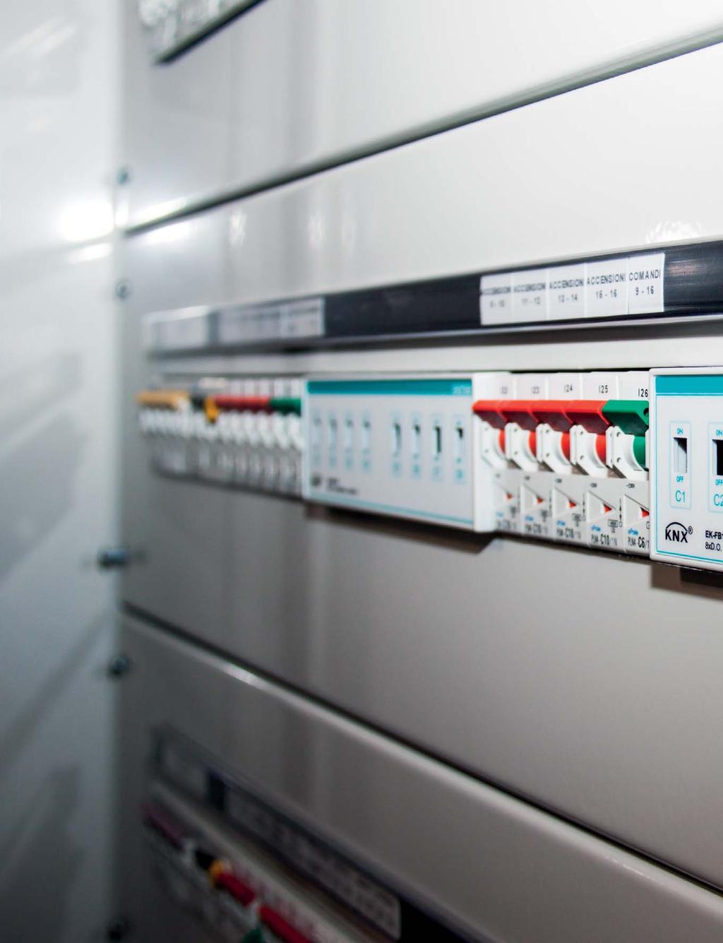
86 86
 159 Index (description) 160")
87 Introduction 07 Wall-mounting devices 18 Rail-mounting devices Power supply units 89 System modules 91 Inputs and actuators 96 Dimmers 103 Thermoregulation and PLC 109 Gateways 116 Metering Supervision 133 Tools 142 Technical section 146 General terms of sale 157 Index (codes) 159 Index (description)
88 TECHNICAL016EN Power supply units RAIL-MOUNTING DEVICES EK-AG1-TP EK-AB1-TP 640 ma bus power supply 640 ma bus power supply with 30 Vdc auxiliary output Power supply of a KNX bus line with max. 64 bus devices connected Reset of the connected bus line through pushbutton LED for output voltage on KNX bus LED for overload / short circuit on KNX bus Integrated decoupling choke Power supply Vac 50/60 Hz Output for auxiliary power supply 30 Vdc - Mounting on standard 35 mm rail (EN 60715) System modules RAIL-MOUNTING DEVICES EK-BD1-TP USB interface EK-BA1-TP Line / area coupler EK-BB1-TP IP interface EK-BC1-TP IP router Suppress device confi guration on the sub line - Enable or disable fi ltering of group messages - Suppress device oriented messages - Trace the traffi c on the sub line - Reduced number of retransmissions - Function pushbutton - Status LED for KNX bus line Status LED for Ethernet - - Mounting on standard 35 mm rail (EN 60715) Plug in program Programming pushbutton - Auxiliary power supply Connection of a PC or laptop to the KNX bus system

89 07 Introduction 18 Wall-mounting devices 87 Rail-mounting devices Supervision 142 Tools 146 Technical section 157 General terms of sale 159 Index (codes) 160 Index (description) 640 ma bus power supply POWER SUPPLY UNITS Description The ekinex 640 ma KNX bus power supply EK-AB1-TP supplies and monitors the 30 Vdc voltage required by the KNX bus for operation. An integrated choke provides for decoupling power supply and bus line. Up to 64 KNX devices may be connected to a single bus line supplied by the 640 ma power supply. Output is protected from overload and short-circuit. The device supports short network voltage interruptions (max. 200 ms). Main Characteristics Plastic casing Connection to bus line with KNX terminal block Connection of 230 Vac power supply with screw terminals Classification climatic 3K5 and mechanical 3M2 (according to EN ) Pollution degree 2 (according to IEC ) Safety class II Installation on 35 mm rail (according to EN 60715) 4 modular units (1 MU = 18 mm) IP20 protection grade (installed device) Weight 150 g Technical data Input voltage 230 Vac, 50/60 Hz Power absorption 22 W Loss < 3 W Output voltage (KNX bus): 30 Vdc +1/-2 Vdc Nominal current: 640 ma Buffer time: 200 ms Delivery Delivery includes a terminal block for connection to the bus. Dimensions [mm] L N V~ ~ 30 V 50/60 Hz I 640 ma = + 45 C 45 ON I > Imax EK-AB1-TP Power supply 640 ma bus KNX Code EK-AB1-TP Package 1 pcs. Configuration and commissioning Not necessary Documentation For more information, see the STEKAB1TP_EN.pdf technical sheet available for download from 89
90 I2 TECHNICAL016EN 640 ma bus power supply with 30 Vdc auxiliary output POWER SUPPLY UNITS Descrizione The ekinex 640 ma KNX bus power supply EK-AG1-TP supplies and monitors the 30 Vdc voltage required by the KNX bus for operation. An integrated choke provides for decoupling power supply and bus line. An additional 30 Vdc output can be used as auxiliary power supply for other devices requiring SELV voltage (Safety Extra Low Voltage). The total current provided by the two outputs (KNX bus line and auxiliary power supply) cannot exceed 640 ma. Output is protected from overload and shortcircuit. The device supports short network voltage interruptions (max. 200 ms). Main Characteristics Plastic casing Connection to bus line with KNX terminal block Connection of auxiliary output with dedicated terminal block (yellow/white) Connection of 230 Vac power supply with screw terminals Classification climatic 3K5 and mechanical 3M2 (according to EN ) Pollution degree 2 (according to IEC ) Safety class II Installation on 35 mm rail (according to EN 60715) 4 modular units (1 MU = 18 mm) IP20 protection grade (installed device) Weight 165 g Technical data Input voltage: 230 Vac, 50/60 Hz Power absorption 22 W Loss < 3 W Output voltage (KNX bus): 30 Vdc Output voltage (auxiliary output): 30 Vdc Nominal current (output total): 640 ma Buffer time: 200 ms Delivery Delivery includes two terminal blocks for connection respectively to the bus and to the devices which need the auxiliary power supply. Dimensions [mm] L N 230 V~ 50/60 Hz I1 bus KNX (30 V ) AUX (30 V ) C I1 + I2 640 ma 45 ON I > Imax EK-AG1-TP Power supply 640 ma with auxiliary output 30 V bus KNX AUX 30 V Code EK-AG1-TP Package 1 pcs. Configuration ad commissioning Not necessary Documentation For more information, see the STEKAG1TP_EN.pdf technical sheet available for download from 90

91 R 07 Introduction 18 Wall-mounting devices 87 Rail-mounting devices Supervision 142 Tools 146 Technical section 157 General terms of sale 159 Index (codes) 160 Index (description) USB interface SYSTEM MODULES Description The ekinex USB interface EK-BD1-TP allows a bidirectional data connection between a PC and a KNX bus system. The device handles the addressing, parameter setting, display, protocol management and diagnosis of KNX bus devices. The device integrates a KNX bus communication module and is realized for mounting on a standard 35 mm DIN-rail. Main characteristics Plastic casing LEDs indicators for data transmission on USB and KNX bus status Connection to bus line with KNX terminal block Connection to PC with USB type B connector Installation on 35 mm rail (according to EN 60715) 2 modular units (1 MU = 18 mm) IP20 protection degree (installed device) Weight 205 g Technical data Power supply (bus side): 30 Vdc SELV, current consumption: max. 10 ma Power supply (PC side): from USB, current consumption: max. 20 ma Delivery Delivery includes a terminal block for connection to the bus. Dimensions [mm] USB 90 KNX EK-BD1-TP USB/KNX interface 45 Code EK-BD1-TP Package 1 pz. Configuration and commissioning Not necessary; the application program APEKBD1TP##.vd4 (download from is available for an ETS project. Documentation For more information, see the STEKBD1TP_EN.pdf technical sheet available for download from 91

92 R TECHNICAL016EN Line / area coupler SYSTEM MODULES Description The ekinex line / area coupler EK-BA1-TP can be used as a line coupler to connect a secondary line to a main line, as an area coupler to connect a main line to a backbone line or as a repeater. The device assures galvanic insulation between the two connected lines and filters the traffic based on installation position or on filter tables in case of group-oriented communications. The frontal LEDs indicate the status of each bus line and facilitate the tracing of communication problems due to bus load or to retransmission on both lines. The device integrates a KNX bus communication module and is realized for mounting on a standard 35 mm DIN-rail. Functions Suppress device configuration on the sub line Enable or disable filtering of group messages Suppress device oriented messages Trace the traffic on the sub line Reduced number of retransmissions Delivery Delivery includes two terminal blocks for connection to the bus lines. Main characteristics Plastic casing Frontal programming pushbutton and LED LEDs indicators for status of KNX bus lines Pushbutton for activating special functions Connection to bus lines with KNX terminal blocks Installation on 35 mm rail (according to EN 60715) 2 modular units (1 MU = 18 mm) IP20 protection degree (installed device) Weight 100 g Technical data 30 Vdc power supply by KNX bus Current consumption (from main bus line) ca.10 ma Dimensions [mm] EK-BA1-TP Line/area coupler bus status 90 traffic MAIN SUB GA PA function Code EK-BA1-TP Package 1 pz. Configuration and commissioning By means of ETS3 software (or later versions) Application program APEKBA1TP##.vd4 (download from Documentation For more information, see the STEKBA1TP_EN.pdf technical sheet available for download from 92
93 R 07 Introduction 18 Wall-mounting devices 87 Rail-mounting devices Supervision 142 Tools 146 Technical section 157 General terms of sale 159 Index (codes) 160 Index (description) IP interface SYSTEM MODULES Description The ekinex EK-BB1-TP IP interface realizes the bidirectional data connection between a PC or a laptop and a KNX bus system through a LAN network. The IP interface supports the tunneling protocol and allows the adressing, parameter setting, display, protocol management and diagnosis of KNX bus devices with ETS. The device integrates a KNX bus communication module and is realized for mounting on a standard 35 mm DIN-rail. The device is powered by the KNX bus and does not require auxiliary power supply. Delivery Delivery includes a terminal block for connection to the bus. Main characteristics Plastic casing Frontal programming pushbutton and LED LEDs indicators for status and data traffic of KNX bus line and Ethernet network Pushbutton for activating special functions Connection to bus line with KNX terminal block Connection to an Ethernet network with a RJ45 connector Installation on 35 mm rail (according to EN 60715) 2 modular units (1 MU = 18 mm) IP20 protection degree (installed device) Weight 70 g Technical data 30 Vdc power supply by KNX bus Current consumption max. 38 ma Dimensions [mm] EK-BB1-TP IP interface 90 bus status IP traffic TP GA PA function Code EK-BB1-TP Package 1 pz. Configuration and commissioning By means of ETS4 software (or later versions) Application program APEKBB1TP##.knxprod (download from Documentation For more information, see the STEKBB1TP_EN.pdf technical sheet available for download from 93


94 R TECHNICAL016EN IP router SYSTEM MODULES Description The ekinex EK-BC1-TP IP router realizes the bidirectional data connection between a PC or a laptop and a KNX bus system through a LAN network. The IP router supports the tunneling protocol and allows the adressing, parameter setting, display, protocol management and diagnosis of KNX bus devices with ETS. The IP router integrates also the line coupling function; through the device telegrams can be exchanged between KNX TP lines on a TCP / IP backbone line. The device integrates a KNX bus communication module and is realized for mounting on a standard 35 mm DIN-rail. The device is powered by the KNX bus and does not require auxiliary power supply. Technical data 30 Vdc power supply by KNX bus Current consumption max. 38 ma Delivery Delivery includes a terminal block for connection to the bus. Main characteristics Plastic casing Frontal programming pushbutton and LED LEDs indicators for status and data traffic of KNX bus line and Ethernet network Pushbutton for activating special functions Connection to bus line with KNX terminal block Connection to an Ethernet network with a RJ45 connector Installation on 35 mm rail (according to EN 60715) 2 modular units (1 MU = 18 mm) IP20 protection degree (installed device) Weight 70 g Dimensions [mm] EK-BB1-TP IP interface 90 bus status IP traffic TP GA PA function Code EK-BC1-TP Package 1 pz. Configuration and commissioning By means of ETS4 software (or later versions) Application program APEKBC1TP##.knxprod (download from Documentation For more information, see the STEKBC1TP_EN.pdf technical sheet available for download from 94
95 07 Introduction 18 Wall-mounting devices 87 Rail-mounting devices Supervision 142 Tools 146 Technical section 157 General terms of sale 159 Index (codes) 160 Index (description) Inputs WALL AND FLUSH-MOUNTING DEVICES EK-CA1-TP 8-fold binary input EK-CB2-TP 6-fold pushbutton interface ON / OFF switching of individual loads or groups of loads Dimming control for lighting devices Operating control for shutters and roller blinds Detecting the state of signaling contacts Recalling and saving of scenes Sending of values on the bus (temperature, brightness, etc.) Control of feedback LEDs - Pushbutton for toggling between manual and automatic operation - Pushbuttons for forced operation of the inputs - Counting of impulses and switching cycles Mounting on standard 35 mm rail (EN 60715) - Actuators WALL-MOUNTING DEVICES EK-FA1-TP 4-fold binary output EK-FB1-TP 8-fold binary output EK-FE1-TP 8-fold binary output / 4-fold blind actuator EK-FF1-TP 16-fold binary output / 8-fold blind actuator ON / OFF switching of individual loads or groups of loads Confi gurable as normally open or normally closed switch Logical gates and forced mode for each channel Manual control by membrane pushbuttons - - Manual control by levers (also without bus voltage) - - Status feedback of output channels through the position of the levers - - Status feedback of output channels through LEDs - - Switching pushbutton manual / automatic mode - - Block function for each channel Auxiliary power supply - - Time scheduling: switching delay for on and off, staircase lighting function Management of scenarios Operating hours counter confi gurable via bus Shutters / blinds operation mode - - Automatic control for protection against direct sunlight - - Automatic control for protection against weather conditions (rain, wind, frost) - - Mounting on standard 35 mm rail (EN 60715) 95
96 TECHNICAL016EN 8-fold binary input INPUTS Description The ekinex EK-CA1-TP binary input has 8 independent input channels for connecting to the KNX bus commands and sensors of traditional type, having potential-free contacts. Thanks to the binary input, it is possible to command and control bus functions with standard switches, pushbuttons or sensors (not natively communicating with the KNX bus) or binary signals made available by other devices. The query voltage of input channels is produced within the device. The device integrates a KNX bus communication module and is realized for mounting on a standard 35 mm DIN-rail. The device is supplied by the KNX bus and does not require auxiliary power supply. Main characteristics Plastic casing Frontal programming pushbutton and LED Membrane keyboard with LED s for status indication Pushbutton for switching operating mode (normal / programming) Connection to bus line with KNX terminal block Connection of inputs with screw terminals Installation on 35 mm rail (according to EN 60715) 4 modular units (1 MU = 18 mm) IP20 protection degree (installed device) Weight 145 g Technical data Power supply Voltage 30 Vdc by KNX bus Current consumption from bus < 13 ma Power on bus 320 mw Inputs Number: 8 Query voltage: < 11 V Query current: < 5 ma Delivery Delivery includes a terminal block for connection to the bus. Dimensions [mm] A 2 3 2A 4 5 3A 6 7 4A 8 9 1B B B B 16 1A 2A 3A 4A 90 1B 2B 3B 4B 45 EK-CA1-TP 8xD.I. Dry Contacts bus KNX Code EK-CA1-TP Package 1 pcs. Configuration and commissioning By means of ETS4 software (or later versions) Application program APEKCA1TP##.knxprod (download from Documentation For more information, see the STEKCA1TP_EN.pdf technical sheet available for download from 96


97 Introduction 18 Wall-mounting devices 87 Rail-mounting devices Supervision 142 Tools 146 Technical section 157 General terms of sale 159 Index (codes) 160 Index (description) 6-fold pushbutton interface INPUTS Description The ekinex EK-CB2-TP 6-fold pushbutton interface is a KNX device that can be used for either input or output. The device has 6 independent channels, integrates a KNX bus communication module and is compact enough for mounting onto flush-mounting boxes. Each of the 6 channels may be used alternatively: - as input, for the connection of switches, pushbuttons or sensors which do not communicate natively with the KNX bus (e.g. signalling contacts); - as output, to drive low consumption LED s. The query voltage of input channels is produced within the device. The device is supplied by the KNX bus and does not require auxiliary power supply. An 8-conductor connection cable with one connection-ready tip is included. Main characteristics Plastic casing Programming pushbutton and LED on the casing Connection to bus line with KNX terminal block Inputs/outputs connections with 250 mm 8-conductor cable IP20 protection degree (installed) Weight 10 g Technical data 30 Vdc power supply through KNX bus Current consumption from bus < 15 ma Channels used as inputs Query voltage: < 11 V Query current: < 5 ma Channels used as inputs Typo: multiplex with current limitation Max. output voltage: 11 V Max. output current: 5 ma Delivery Delivery includes a terminal block for connection to the bus and an 8-conductor connection cable with a connection-ready end and a free end. Dimensions [mm] black 2 red 3 white 4 green 5 yellow 6 blue 7 orange 8 black 2 bus KNX 1 8 Code EK-CB2-TP Package 1 pcs. Configuration and commissioning By means of ETS4 software (or later versions) Application program APEKCB2TP##.knxprod (download from Documentation For more information, see the STEKCB2TP_EN.pdf technical sheet available for download from 97

98 0N 0FF 0N 0FF 0N 0FF 0N 0FF TECHNICAL016EN 4-fold binary output ACTUATORS Description The ekinex EK-FA1-TP binary output allows to command 4 groups of loads independently; to this purpose, the device has outputs fitted with potential-free relays. The device s latching relays guarantee the upkeep of command status even in the case of bus power failures. The front levers indicate the status of each output channel and, in case of emergency, allow manual command (by means of a tool) of the loads. The device integrates a KNX bus communication module and is realized for mounting on a standard 35 mm DIN-rail. The device is supplied by the KNX bus and does not require auxiliary power supply. Main characteristics Plastic casing Frontal programming pushbutton and LED Connection to bus line with KNX terminal block Connection of outputs with screw terminals Overvoltage class III (according to EN ) Classification climatic 3K5 and mechanical 3M2 (according to EN ) Pollution degree 2 (according to IEC ) Installation on 35 mm rail (according to EN 60715) 4 modular units (1 MU = 18 mm) IP20 protection degree (installed device) Weight 205 g Technical data Power supply 30 Vdc voltage by KNX bus Current consumption from bus < 12 ma Power from bus 360 mw Outputs 4 latch relays Nominal voltage (U n ): 230 Vac Nominal current (I n ): 10 A Switched power: 2200 W Delivery Delivery includes a terminal block for connection to the bus. Dimensions [mm] C1 C2 C3 C4 90 C1 C2 C3 C4 45 EK-FA1-TP 4xD.O. 10A/230Vac ~ 50/60 Hz bus KNX Code EK-FA1-TP Package 1 pcs. Configuration and commissioning By means of ETS4 software (or later versions) Application program APEKFA1TP##.knxprod (download from Documentation For more information, see the STEKFA1TP_EN.pdf technical sheet available for download from 98
 160 Index (description) 8-fold binary output ACTUATORS Description The ekinex EK-FA1-TP binary output allows to command 8 groups of loads independently; to this purpose, the device")
99 0N 0FF 0N 0FF 0N 0FF 0N 0FF 0N 0FF 0N 0FF 0N 0FF 0N 0FF 07 Introduction 18 Wall-mounting devices 87 Rail-mounting devices Supervision 142 Tools 146 Technical section 157 General terms of sale 159 Index (codes) 160 Index (description) 8-fold binary output ACTUATORS Description The ekinex EK-FA1-TP binary output allows to command 8 groups of loads independently; to this purpose, the device has outputs fitted with potential-free relays. The device s latching relays guarantee the upkeep of command status even in the case of bus power failures. The front levers indicate the status of each output channel and, in case of emergency, allow manual command (by means of a tool) of the loads. The device integrates a KNX bus communication module and is realized for mounting on a standard 35 mm DIN-rail. The device is supplied by the KNX bus and does not require auxiliary power supply Main characteristics Plastic casing Frontal programming pushbutton and LED Connection to bus line with KNX terminal block Connection of outputs with screw terminals Overvoltage class III (according to EN ) Classification climatic 3K5 and mechanical 3M2 (according to EN ) Pollution degree 2 (according to IEC ) Installation on 35 mm rail (according to EN 60715) 8 modular units (1 MU = 18 mm) IP20 protection degree (installed device) Weight 385 g Technical data Power supply 30 Vdc voltage by KNX bus Current consumption from bus < 12 ma Power from bus 360 mw Outputs 4 latch relays Nominal voltage (U n ): 230 Vac Nominal current (I n ): 10 A Switched power: 2200 W Delivery Delivery includes a terminal block for connection to the bus. Dimensions [mm] C1 C2 C3 C4 C5 C6 C7 C8 90 C1 C2 C3 C4 C5 C6 C7 C8 45 EK-FB1-TP 8xD.O. 10A/230Vac ~ 50/60 Hz bus KNX Code EK-FB1-TP Package 1 pcs. Configuration and commissioning By means of ETS4 software (or later versions) Application program APEKFB1TP##.knxprod (download from Documentation For more information, see the STEKFB1TP_EN.pdf technical sheet available for download from 99
100 A B A B A B A B TECHNICAL016EN 8-fold binary output/ 4-fold blind actuator ACTUATORS Description The ekinex EK-FE1-TP binary output / blind actuator allows to command 8 groups of loads or control 4 drives for motorised blinds independently. The device is fitted with membrane pushbuttons for manual command (even in the absence of bus power) and LED s for status indication; a pushbutton allows to switch between automatic and manual operation modes. The device integrates a KNX bus communication module and is realized for mounting on a standard 35 mm DIN-rail. The device is supplied by the KNX bus and requires an additional 230 Vac power supply to operate. Main characteristics Plastic casing Frontal programming pushbutton and LED Membrane keyboard with LED s for status indication Pushbutton for switching operating mode (normal / programming) Connection to bus line with KNX terminal block Connection of outputs and 230 Vac power supply with screw terminals Overvoltage class III (according to EN ) Classification climatic 3K5 and mechanical 3M2 (according to EN ) Pollution degree 2 (according to IEC ) Installation on 35 mm rail (according to EN 60715) 4 modular units (1 MU = 18 mm) IP20 protection degree (installed device) Weight 315 g Technical data Power supply Voltage (loads) 230 Vac 50/60 Hz Voltage (electronics) 30 Vdc by KNX bus Current consumption from bus < 10 ma Power on bus < 240 mw Outputs Number: 8 or 4 independent channels (depending on device use) Nominal voltage (U n ): 230 Vac Nominal current (I n ): 16 A (10 A) Max. switched power: 4000 VA Delivery Delivery includes a terminal block for connection to the bus. Dimensions [mm] 3 4 1A B 5 6 2A B A B A B A 2A 3A 4A 90 1B 2B 3B 4B 45 EK-FE1-TP 8xD.O. 10A/230Vac ~ 50/60 Hz 4xBlind 10A/230Vac ~ 50/60 Hz 230V~ 50/60Hz L N bus KNX 1 2 Code EK-FE1-TP Package 1 pcs. Configuration and commissioning By means of ETS4 software (or later versions) Application program APEKFE1TP##.knxprod (download from Documentation For more information, see the STEKFE1TP_EN.pdf technical sheet available for download from 100
101 A B A B A B A B A B A B A B A B 07 Introduction 18 Wall-mounting devices 87 Rail-mounting devices Supervision 142 Tools 146 Technical section 157 General terms of sale 159 Index (codes) 160 Index (description) 16-fold binary output/ 8-fold blind actuator ACTUATORS Description The ekinex EK-FE1-TP binary output / blind actuator allows to command 16 groups of loads or control 8 drives for motorised blinds independently. The device is fitted with membrane pushbuttons for manual command (even in the absence of bus power) and LED s for status indication; a pushbutton allows to switch between automatic and manual operation modes. The device integrates a KNX bus communication module and is realized for mounting on a standard 35 mm DIN-rail. The device is supplied by the KNX bus and requires an additional 230 Vac power supply to operate. Main characteristics Plastic casing Frontal programming pushbutton and LED Membrane keyboard with LED s for status indication Pushbutton for switching operating mode (normal / programming) Connection to bus line with KNX terminal block Connection of outputs and 230 Vac power supply with screw terminals Overvoltage class III (according to EN ) Classification climatic 3K5 and mechanical 3M2 (according to EN ) Pollution degree 2 (according to IEC ) Installation on 35 mm rail (according to EN 60715) 8 modular units (1 MU = 18 mm) IP20 protection degree (installed device) Weight 595 g Technical data Power supply Voltage (loads) 230 Vac 50/60 Hz Voltage (electronics) 30 Vdc by KNX bus Current consumption from bus < 10 ma Power on bus < 240 mw Outputs Number: 16 or 8 independent channels (depending on device use) Nominal voltage (U n ): 230 Vac Nominal current (I n ): 16 A (10 A) Max. switched power: 4000 VA Delivery Delivery includes a terminal block for connection to the bus. Dimensions [mm] 3 4 1A B 5 6 2A B 7 8 3A B A B A B A B A B A B 70 1A 2A 3A 4A 5A 6A 7A 8A 90 1B 2B 3B 4B 5B 6B 7B 8B 45 EK-FF1-TP 16xD.O. 10A/230Vac ~ 50/60 Hz 8xBlind 10A/230Vac ~ 50/60 Hz 230V~ 50/60Hz L N bus KNX 1 2 Code EK-FF1-TP Package 1 pcs. Configuration and commissioning By means of ETS4 software (or later versions) Application program APEKFF1TP##.knxprod (download from Documentation For more information, see the STEKFF1TP_EN.pdf technical sheet available for download from 101
102 TECHNICAL016EN Dimmer RAIL-MOUNTING DEVICES EK-GA1-TP 2-fold dimming actuator EK-GB1-TP 4-fold dimming actuator EK-GC1-TP 4-fold RGBW LED dimmer EK-GC3-TP 4-fold RGBW LED dimmer (recessed mounting) EK-GF1-TP 4-fold 0-10 V actuator EK-BK1-TP DMX-KNX Gateway ON/OFF switching of single or groups of lighting device - Brightness regulation and adjusting the light intensity - Logical gates and forced mode for each channel - Manual control by membrane pushbuttons - Status feedback of output channels through LEDs - Block function for each channel - Without auxiliary power supply - Time scheduling: switching delay for on and off, staircase lighting function - Integration in scenarios Operating hours counter confi gurable via bus - Fade adjustable ramps - RGB / HSV operating mode Electrically insulated RS485 serial communication port way DIP switch to activate the line terminator (120 Ohm) DMX master communication kbaud communication speed Device addressing from 0 to byte register writing on a maximum of 512 DMX devices KNX TP (twisted pair) 9600 baud communication port Volatile support memory with "image KNX" buffer of 1440 bytes Dedicated confi guration program Mounting on standard 35 mm rail (EN 60715) - 102

103 07 Introduction 18 Wall-mounting devices 87 Rail-mounting devices Supervision 142 Tools 146 Technical section 157 General terms of sale 159 Index (codes) 160 Index (description) 2-fold dimming actuator DIMMERS Description The ekinex EK-GA1-TP dimming actuator allows to command and regulate the light intensity of 2 groups of lighting devices. The device is suitable for the control of resistive, inductive and capacitive loads powered with 230 Vac. Different types of loads can be connected to different channels. The device is fitted with membrane pushbuttons for manual command and LEDs for status indication; a pushbutton allows the switching between automatic or manual operation modes. The device integrates a KNX bus communication module and is realised for mounting on a standard 35 mm DIN-rail. The device is powered by the KNX bus and requires an additional 230 Vac power supply to operate the loads. Main characteristics Plastic casing Frontal programming pushbutton and LED Membrane keyboard with LEDs for status indication of outputs Pushbutton for switching operating mode (normal / programming) Connection to bus line with KNX terminal block Connection of outputs and 230 Vac power supply with screw terminals Installation on 35 mm rail (according to EN 60715) 4 modular units (1 MU = 18 mm) IP20 protection degree (installed device) Weight 160 g Technical data Power supply Voltage (loads): 230 Vac 50/60 Hz Voltage (electronics): 30 Vdc by KNX bus Current consumption from bus: < 13 ma Max. power from bus: 320 mw Outputs Number: 2 Max. controlled power: 300 W Min. controlled power: 10 W Delivery Delivery includes a terminal block for connection to the bus. Dimensions [mm] ~/ 3 4 C1 72 ~/ 5 6 C C1 C2 45 EK-GA1-TP 2xDimmer W 230Vac ~ 50/60 Hz 230V~ 50/60Hz L N bus KNX 1 2 Code EK-GA1-TP Package 1 pcs. Configuration and commissioning By means of ETS4 software (or later versions) Application program APEKGA1TP##.knxprod (download from Documentation For more information, see the STEKGA1TP_EN.pdf technical sheet available for download from 103

104 TECHNICAL016EN 4-fold dimming actuator DIMMERS Description The ekinex EK-GB1-TP dimming actuator allows to command and regulate the light intensity of 4 groups of lighting devices. The device is suitable for the control of resistive, inductive and capacitive loads powered with 230 Vac. Different types of loads can be connected to different channels. The device is fitted with membrane pushbuttons for manual command and LEDs for status indication; a pushbutton allows the switching between automatic or manual operation modes. The device integrates a KNX bus communication module and is realised for mounting on a standard 35 mm DIN-rail. The device is powered by the KNX bus and requires an additional 230 Vac power supply to operate the loads. Main characteristics Plastic casing Frontal programming pushbutton and LED Membrane keyboard with LEDs for status indication of outputs Pushbutton for switching operating mode (normal / programming) Connection to bus line with KNX terminal block Connection of outputs and 230 Vac power supply with screw terminals Installation on 35 mm rail (according to EN 60715) 8 modular units (1 MU = 18 mm) IP20 protection degree (installed device) Weight 300 g Technical data Power supply Voltage (loads): 230 Vac 50/60 Hz Voltage (electronics): 30 Vdc by KNX bus Current consumption from bus: < 15 ma Max. power from bus: 360 mw Outputs Number: 4 Max. controlled power: 300 W Min. controlled power: 10 W Delivery Delivery includes a terminal block for connection to the bus. Dimensions [mm] ~/ 3 4 C1 ~/ 5 6 C2 144 ~/ 7 8 C3 ~/ 9 10 C C C2 C3 C4 45 EK-GB1-TP 4xDimmer W 230Vac ~ 50/60 Hz 230V~ 50/60Hz L N bus KNX 1 2 Code EK-GB1-TP Package 1 pcs. Configuration and commissioning By means of ETS4 software (or later versions) Application program APEKGB1TP##.knxprod (download from Documentation For more information, see the STEKGB1TP_EN.pdf technical sheet available for download from 104


105 R 07 Introduction 18 Wall-mounting devices 87 Rail-mounting devices Supervision 142 Tools 146 Technical section 157 General terms of sale 159 Index (codes) 160 Index (description) 4-fold RGBW LED dimmer DIMMERS Description The ekinex 4-fold RGBW LED dimmer allows to regulate independently the light intensity emitted by 4 LED strips at 12/24 Vdc or, alternatively, to regolate the light intensity and the colour emitted by a RGB or RGBW LED strip. The device is suitable for use with LED strips powered at constant voltage. The selection of the colour can be made optionally in HSV or RGB mode. Scenarios, predefined sequences, sequence repetition and random functions are available; the dimming speed and the holding time are programmable. The device is fitted with membrane pushbuttons for manual command and LEDs for status indication; a pushbutton allows the switching between automatic or manual operation modes. The device integrates a KNX bus communication module and is realised for mounting on a standard 35 mm DIN-rail. The device is powered by the KNX bus and requires an additional Vdc to supply the controlled loads. Technical data Power supply Voltage (strip LED): max 30 Vdc, 16 A Voltage (control): 30 Vdc by KNX bus Outputs Number: 4 Load current for each channel: 2 A (EK-GC1-TP) or 4 A (EK-GD1-TP) Delivery Delivery includes a terminal block for connection to the bus. Main characteristics Plastic casing Frontal programming pushbutton and LED Membrane keyboard with LEDs for status indication of outputs Pushbutton for switching operating mode (normal / programming) CH pushbutton for individual or simultaneous channels control HSV / RGB pushbutton colour control mode Auxiliary dry contact to disconnect load power supply during standby Connection to bus line with KNX terminal block Connection of outputs and Vdc power supply with screw terminals Installation on 35 mm rail (according to EN 60715) 4 modular units (1 MU = 18 mm) IP20 protection degree (installed device) Dimensions [mm] 90 EK-GC1-TP 4xDimmer LED RGBW C1/R V V C2/G C3/B CA/W C3 C1 C2 C4 H S V - + CH Area Line Dev. HSV 230V-/10 A max bus KNX Code Max. load Package EK-GC1-TP 2 A 1 pcs. EK-GD1-TP 4 A 1 pcs. Configuration and commissioning By means of ETS4 software (or later versions) Application program APEKGC1TP##.knxprod (download from Documentation For more information, see the STEKGC1TP_EN.pdf technical sheet available for download from (under preparation) 105

106 R TECHNICAL016EN 4-fold RGBW LED dimmer DIMMERS Description The ekinex 4-fold RGBW LED dimmer allows to regulate independently the light intensity emitted by 4 LED strips at 12/24 Vdc or, alternatively, to regolate the light intensity and the colour emitted by a RGB or RGBW LED strip. The device is suitable for use with LED strips powered at constant voltage. The selection of the colour can be made optionally in HSV or RGB mode. Scenarios, predefined sequences, sequence repetition and random functions are available; the dimming speed and the holding time are programmable. The device integrates a KNX bus communication module and is realised for recessed mounting. The device is powered by the KNX bus and requires an additional Vdc to supply the controlled loads. Main characteristics Plastic casing Programming pushbutton and LED on the casing Auxiliary dry contact to disconnect load power supply during standby Connection to bus line with KNX terminal block Connection of outputs and power supply with screw terminals Recessed mounting IP20 protection degree (installed device) Technical data Power supply Voltage (strip LED): max 30 Vdc, 8 A Voltage (control): 30 Vdc by KNX bus Outputs Number: 4 Load current for each channel: 2 A Delivery Delivery includes a terminal block for connection to the bus. Dimensions [mm] V- 10 A EK-GC3-TP 4xDimmer LED RGBW Area Line Dev. COM C1 R 4 C2 G 5 C3 B 6 C4 W 7 25 Code EK-GC3-TP Package 1 pcs. Configuration and commissioning By means of ETS4 software (or later versions) Application program APEKGC3TP##.knxprod (download from Documentation For more information, see the STEKGC3TP_EN.pdf technical sheet available for download from (under preparation) 106

107 R 07 Introduction 18 Wall-mounting devices 87 Rail-mounting devices Supervision 142 Tools 146 Technical section 157 General terms of sale 159 Index (codes) 160 Index (description) 4-fold 0-10 V actuator DIMMERS Description The ekinex 4-fold 0-10 V actuator EK-GF1-TP can be used as 0-10 V control output device or, alternatively, for controlling dimmerable LED power supply units. When used for LED controlling, the selection of the colour can be made optionally in HSV or RGB mode. Scenarios, predefined sequences, sequence repetition and random functions are available; the dimming speed and the holding time are programmable. The device is fitted with membrane pushbuttons for manual command and LEDs for status indication; a pushbutton allows the switching between automatic or manual operation modes. The device integrates a KNX bus communication module and is realised for mounting on a standard 35 mm DIN-rail. The device is powered by the KNX bus. Main characteristics Plastic casing Frontal programming pushbutton and LED Membrane keyboard with LEDs for status indication of outputs Pushbutton for switching operating mode (normal / programming) CH pushbutton for individual or simultaneous channels control HSV / RGB pushbutton colour control mode Connection to bus line with KNX terminal block Connection of outputs with screw terminals Installation on 35 mm rail (according to EN 60715) 4 modular units (1 MU = 18 mm) IP20 protection degree (installed device) Technical data Power supply Voltage (control): 30 Vdc by KNX bus Voltage (outputs) 230 Vac, max. 6 W Outputs Number: 4 Range: 0-10 V or 1-10V Max. current for each channel: 50 ma Delivery Delivery includes a terminal block for connection to the bus and a terminal block for connection to the auxiliary power supply. Dimensions [mm] Aux V C1/R C2/G C3/B CA/W C3 C1 C2 C4 H S V CH 45 EK-GF1-TP 4xOutput 0-10 V HSV Area Line Dev. L N bus KNX Code EK-GF1-TP Package 1 pcs. Configuration and commissioning By means of ETS4 software (or later versions) Application program APEKGF1TP##.knxprod (download from Documentation For more information, see the STEKGF1TP_EN.pdf technical sheet available for download from (under preparation) 107
108 TECHNICAL016EN Thermoregulation and PLC RAIL-MOUNTING DEVICES EK-HA1-TP Fan-coil actuator / controller 3-speed fan control EK-HB1-TP Fan-coil actuator / controller 0-10 V fan control EK-HC1-TP Fan-coil actuator / controller full version EK-HE1-TP 8-fold actuator / controller for electrothermal valve drives EK-HH1-TP Mixing actuator EK-IA1-TP CODESYS PLC with KNX interface Power 30 Vdc from KNX bus Auxiliary power supply 230 Vac 50/60 Hz - Analog input (passive temperature sensors 10 kω NTC at 25 C) - - Digital input (potential-free) - - Output relays - - Output triac relays Output 0-10V (high impedence signal control) Membrane keyboard for manual/automatic control with status indication LEDs LC-display pipe hydraulic distribution systems applications pipe hydraulic distribution systems applications Actuator - - Internal controller - Air fl ow terminal: ventilation Air fl ow terminal: convector Air fl ow terminal: fan-coil Air fl ow terminal: fan-coil + 2 electrical stage Underfl oor and ceiling systems distribution Underfl oor and ceiling mixing valve systems Mounting on standard 35 mm rail (EN 60715) 108
109 R 07 Introduction 18 Wall-mounting devices 87 Rail-mounting devices Supervision 142 Tools 146 Technical section 157 General terms of sale 159 Index (codes) 160 Index (description) Fancoil actuator / controller 3-speed fan control THERMOREGULATION Description The ekinex EK-HA1-TP fancoil actuator / controller allows to control a fan coil unit for the air conditioning of a room. The device can perform the function of simple actuator in combination with a KNX room thermostat or that of actuator / controller with acquisition of the temperature value by a KNX room sensor or a probe connected to an analog input. The device is suitable for 2-pipe hydraulic distribution systems with ON / OFF control of one electrothermal shut-off valve actuator and a 3-speed fan. The outputs not used to control the fan coil unit can be configured as binary output channels for different functions. The device is equipped with 2 inputs freely configurable as analog or digital. The device integrates a KNX bus communication module and is realized for mounting on a standard 35 mm DIN-rail. The device is supplied by the KNX bus and requires an additional 230 Vac power supply to operate. Main characteristics Plastic casing Frontal programming pushbutton and LED Connection to bus line with KNX terminal block Connection of inputs, outputs and 230 Vac power supply with screw terminals Classification climatic 3K5 and mechanical 3M2 (according to EN ) Overvoltage class III (according to EN ) Pollution degree 2 (according to IEC ) 35 mm rail mounting (according to EN 60715) 4 modular units (1 MU = 18 mm) IP20 protection degree (installed device) Weight 175 g Technical data Power supply Voltage (loads) 230 Vac 50/60 Hz Voltage (electronics) 30 Vdc by KNX bus Inputs 2 freely configurable for passive temperature sensors (10 kω NTC at 25 C) or as potential-free binary inputs Outputs 3 interlocked relay outputs to control a 3-speed fan (or configurable as binary outputs for different applications) 1 relay SPST (single pole, single throw) to control an ON / OFF valve (in 2-pipe hydraulic distribution systems) Delivery Delivery includes a terminal block for connection to the bus. Dimensions [mm] C 11 3 IN1 V V2 13 V DO IN EK-HA1-TP Fan-coil actuator/controller Area Line Dev. 230Vac-50/60Hz L N bus KNX 1 2 Code EK-HA1-TP Package 1 pcs. Configuration and commissioning By means of ETS4 software (or later versions) Application program APEKHA1TP##.knxprod (download from Documentation For more information, see the STEKHA1TP_EN.pdf technical sheet available for download from 109

110 R TECHNICAL016EN Fancoil actuator / controller 0-10 V fan control THERMOREGULATION Description The ekinex EK-HB1-TP fancoil actuator / controller allows to control a fan coil unit for the air conditioning of a room. The device can perform the function of simple actuator in combination with a KNX room thermostat or that of actuator / controller with acquisition of the temperature value by a KNX room sensor or a probe connected to an analog input. The device is suitable for 2-pipe hydraulic distribution systems with ON / OFF control of one electrothermal shut-off valve actuator and a fan with brushless motor. The outputs not used to control the fan coil unit can be configured as binary output channels for different functions. The device is equipped with 2 inputs freely configurable as analog or digital. The device integrates a KNX bus communication module and is realized for mounting on a standard 35 mm DIN-rail. The device is supplied by the KNX bus and requires an additional 230 Vac power supply to operate. Main characteristics Plastic casing Frontal programming pushbutton and LED Connection to bus line with KNX terminal block Connection of inputs, outputs and 230 Vac power supply with screw terminals Classification climatic 3K5 and mechanical 3M2 (according to EN ) Overvoltage class III (according to EN ) Pollution degree 2 (according to IEC ) 35 mm rail mounting (according to EN 60715) 4 modular units (1 MU = 18 mm) IP20 protection degree (installed device) Weight 175 g Technical data Power supply Voltage (loads) 230 Vac 50/60 Hz Voltage (electronics) 30 Vdc by KNX bus Inputs 2 freely configurable for passive temperature sensors (10 kω NTC at 25 C) or as potential-free binary inputs Outputs 1 to control a brushless motor driven fan with 0-10 V signal 1 relay SPST (single pole, single throw) to control an ON / OFF valve (in 2-pipe hydraulic distribution systems) Delivery Delivery includes a terminal block for connection to the bus. Dimensions [mm] 72 DO IN1 4 IN V EK-HB1-TP Fan-coil actuator/controller Area Line Dev. 230Vac-50/60Hz L N bus KNX 1 2 Code EK-HB1-TP Package 1 pcs. Configuration and commissioning By means of ETS4 software (or later versions) Application program APEKHB1TP##.knxprod (download from Documentation For more information, see the STEKHB1TP_EN.pdf technical sheet available for download from 110
111 R 07 Introduction 18 Wall-mounting devices 87 Rail-mounting devices Supervision 142 Tools 146 Technical section 157 General terms of sale 159 Index (codes) 160 Index (description) Fancoil actuator / controller full version THERMOREGULATION Description The ekinex EK-HC1-TP fancoil actuator / controller allows to control a fan coil unit for the air conditioning of a room. The device can perform the function of simple actuator in combination with a KNX room thermostat or that of actuator / controller with acquisition of the temperature value by a KNX room sensor or a probe connected to an analog input. The device is suitable for 2 or 4-pipe hydraulic distribution systems with ON / OFF control of one or two electrothermal shut-off valve actuators and a 3-speed fan or a brushless motor driven fan. The outputs not used to control the fan coil unit can be configured as binary output channels for different functions. The device is equipped with 3 inputs freely configurable as analog or digital. The device is fitted with membrane pushbuttons for manual command and LED s for status indication; a pushbutton allows to switch between automatic and manual operation modes. The device integrates a KNX bus communication module and is realized for mounting on a standard 35 mm DIN-rail. The device is supplied by the KNX bus and requires an additional 230 Vac power supply to operate. Technical data Power supply Voltage (loads) 230 Vac 50/60 Hz Voltage (electronics) 30 Vdc by KNX bus Inputs 3 freely configurable for passive temperature sensors (10 kω NTC at 25 C) or as potential-free binary inputs Outputs 1 to control a brushless motor driven fan with 0-10 V signal 3 interlocked relay outputs to control a 3-speed fan (or configurable as binary outputs for different applications) 2 relay SPST (single pole, single throw) to control two ON / OFF valves (in 2 or 4-pipe hydraulic distribution systems) Main characteristics Plastic casing Frontal programming pushbutton and LED Membrane keyboard with LED s for status indication Pushbutton for switching operating mode (normal / programming) Connection to bus line with KNX terminal block Connection of inputs, outputs and 230 Vac power supply with screw terminals Classification climatic 3K5 and mechanical 3M2 (according to EN ) Overvoltage class III (according to EN ) Pollution degree 2 (according to IEC ) 35 mm rail mounting (according to EN 60715) 4 modular units (1 MU = 18 mm) IP20 protection degree (installed device) Weight 205 g Delivery Delivery includes a terminal block for connection to the bus. Dimensions [mm] 90 C 11 3 IN1 V V IN2 2 bus KNX V Area Line Dev. 3 EK-HC1-TP Fan-coil actuator/controller DO1 DO IN3 8 L 9 DO1 DO2 0-10V Vac-50/60Hz N Configuration and commissioning Code EK-HC1-TP Package 1 pcs. By means of ETS4 software (or later versions) Application program APEKHC1TP##.knxprod (download from Documentation For more information, see the STEKHC1TP_EN.pdf technical sheet available for download from 111
112 TECHNICAL016EN 8-fold actuator / controller for electrothermal valve drives THERMOREGULATION Description The ekinex EK-HE1-TP actuator / controller allows to control electrothermal actuators or servomotors in hydronic systems for room heating and / or cooling. The device can perform the function of simple actuator in combination with one or more KNX room thermostats or that of actuator / controller with acquisition of the temperature value by one or more KNX sensors. The device is suitable for 2 or 4-pipe hydraulic distribution systems with ON / OFF control of electrothermal shut-off valve actuators. The device is fitted with membrane pushbuttons for manual command and LED s for status indication; a pushbutton allows to switch between automatic and manual operation modes. The device integrates a KNX bus communication module and is realized for mounting on a standard 35 mm DIN-rail. The device is supplied by the KNX bus and requires an additional 230 Vac power supply to operate. Technical data Power supply Voltage (loads) 230 Vac 50/60 Hz Voltage (electronics) 30 Vdc by KNX bus Outputs 8 TRIAC relays to control ON / OFF zone valve drives Delivery Delivery includes a terminal block for connection to the bus. Main characteristics Plastic casing Frontal programming pushbutton and LED Membrane keyboard with LED s for status indication Pushbutton for switching operating mode (normal / programming) Connection to bus line with KNX terminal block Connection of outputs and 230 Vac power supply with screw terminals Classification climatic 3K5 and mechanical 3M2 (according to EN ) Overvoltage class III (according to EN ) Pollution degree 2 (according to IEC ) 35 mm rail mounting (according to EN 60715) 4 modular units (1 MU = 18 mm) IP20 protection degree (installed device) Dimensions [mm] A 2 3 2A 4 5 3A 6 7 4A B 2B 3B 4B 1A 2A 3A 4A B 2B 3B 4B 45 EK-HE1-TP Valve actuator 8-fold Over current Area Line bus KNX Dev. Code EK-HE1-TP Package 1 pcs. Configuration and commissioning By means of ETS4 software (or later versions) Application program APEKHE1TP##.knxprod (download from Documentation For more information, see the STEKHE1TP_EN.pdf technical sheet available for download from 112
113 T1 T2 T3 0-10V 07 Introduction 18 Wall-mounting devices 87 Rail-mounting devices Supervision 142 Tools 146 Technical section 157 General terms of sale 159 Index (codes) 160 Index (description) Mixing actuator THERMOREGULATION Description The ekinex EK-HH1-TP mixing actuator allows the control of 3 floating points or 0-10 V servo-motor for mixing valves. The flow temperature of the conveying fluid can be set at a fixed point, with external climatic compensation and with external climatic compensation plus internal conditions recalibration. The regulation modes are selectable separately for heating and cooling. The device is particularly suitable for underfloor or ceiling heating and cooling radiant panels applications in combination with ekinex room thermostats with integrated temperature and humidity sensor. A 0-10 V output allows the remote setting of a heat pump temperature setpoint value. The startup function enables a radiant floors drying concrete phase according to EN 1264 standard. The membrane keyboard allows the manual command and includes LED s for status indication; the LC-display allows displaying / setting of the main working parameters. The device integrates a KNX bus communication module and is realized for mounting on a standard 35 mm DIN-rail. The device is supplied by the KNX bus and requires an additional 230 Vac power supply to operate. Technical data Power supply Voltage (loads) 230 Vac 50/60 Hz Voltage (electronics) 30 Vdc by KNX bus Inputs 3 freely configurable for passive temperature sensors (10 kω NTC at 25 C) or as potential-free binary inputs 2 potential-free binary inputs Outputs 2 TRIAC to command a 3 floating points mixing valve actuator 1 with 0-10 V signal to remotely control a temperature setpoint value (for heat pumps) 3 relays SPST (single pole, single throw) to control ON / OFF zone valve drives Main characteristics Plastic casing Frontal programming pushbutton and LED Membrane keyboard with LED s for status indication Pushbutton for switching operating mode (normal / programming) Connection to bus line with KNX terminal block Connection of inputs, outputs and 230 Vac power supply with screw terminals Classification climatic 3K5 and mechanical 3M2 (according to EN ) Overvoltage class III (according to EN ) Pollution degree 2 (according to IEC ) 35 mm rail mounting (according to EN 60715) 8 modular units (1 MU = 18 mm) IP20 protection degree (installed device) Delivery Delivery includes a terminal block for connection to the bus. Dimensions [mm] 90 AI1 3 4 DI T1 T2 T3 Setpoint AI2 5 6 DI EK-HH1-TP Mixing group controller AI3 7 8 Temperature [ C] AO PWM OK Condensation alarm Temperature alarm DO DO1 Cooling TR1 TR DO TR1 DO2 Heating 230V~ 50/60Hz L DO TR2 DO3 N bus KNX 1 2 Code EK-HH1-TP Package 1 pcs. Configuration and commissioning By means of ETS4 software (or later versions) Application program APEKHH1TP##.knxprod (download from Documentation For more information, see the STEKHH1TP_EN.pdf technical sheet available for download from 113
; it incorporates an interface to the KNX bus and a USB port for programming.")
114 TECHNICAL016EN CODESYS PLC with KNX interface PLC Description The ekinex EK-IA1-TP PLC allows to realize complex control and regulation logics for the automation of homes and buildings, integrating basic KNX functions. The device is completely programmable by using the CODESYS* development environment (V3 release); it incorporates an interface to the KNX bus and a USB port for programming. The device is entirely supplied at SELV voltage by the KNX bus and does not require auxiliary power supply. It is delivered with a software tool to list all variables used for programming the device. Delivery Delivery includes a terminal block for connection to the bus. Further information CODESYS (COntroller DEvelopment SYStem) is a trademark of 3S-Smart Software Solutions GmbH, Kempten (Germany). The CODESYS platform complies with standard IEC Programmable controllers - Part 3: Programming languages. For more information, also consult Main characteristics Plastic casing Connection to bus line with KNX terminal blockx Connection to PC with USB connector Classification climatic 3K5 and mechanical 3M2 (according to EN ) Overvoltage class III (according to EN ) Pollution degree 2 (according to IEC ) 35 mm rail mounting (according to EN 60715) 4 modular units (1 MU = 18 mm) IP20 protection degree (installed device) Weight 130 g Technical data Power supply 30 Vdc voltage by KNX bus Dimensions [mm] EK-IA1-TP PLC CODESYS with KNX interface bus KNX Code EK-IA1-TP Package 1 pcs. Configuration and commissioning Import of ETS database by means of a dedicated software tool Documentation For more information, see the STEKIA1TP_EN.pdf technical sheet available for download from 114
115 07 Introduction 18 Wall-mounting devices 87 Rail-mounting devices Supervision 142 Tools 146 Technical section 157 General terms of sale 159 Index (codes) 160 Index (description) Gateways RAIL-MOUNTING DEVICES EK-BH1-TP-485 Gateway Modbus RS485-KNX EK-BH1-TP-TCP Gateway Modbus TCP/IP-KNX EK-BJ1-TP-IP Gateway BACnet IP-KNX EK-BJ1-TP-MSTP Gateway BACnet MS/TP-KNX EK-BK1-TP Gateway DMX-KNX EK-BM1-TP-xx Gateway M-Bus-KNX EK-BN1-TP Gateway PROFINET-KNX EK-BP1-TP Gateway DALI-KNX Auxiliary power supply Electrically insulated RS485 serial communication port way DIP switch to activate the line terminator (120 Ohm) Modbus master RTU (Remote Terminal Unit) communicaton BACnet slave communication BACnet communication PROFINET slave communication BACnet records exchange PROFINET records exchange DMX master communication kbaud communication speed From 1200 to baud communication speed from 3000 to baud communication speed Ethernet (IEEE 802.3) communication port, RJ45 connector M-Bus communication port Device addressing from 1 to Device addressing from 0 to Device addressing from 0 to Register exchange of Coil, Input, and Input Register Holding - Register type Reading and writing of single and multiple registers byte register writing on a maximum of 512 DMX devices Volatile support memory with image Modbus of 1440 byte Volatile support memory with image BACnet of 1440 byte Volatile support memory with image M-Bus of 1440 byte Volatile support memory with image PROFINET of 1440 byte KNX TP (twisted pair) 9600 baud communication port Volatile support memory with image KNX of 1440 byte Additional plug-in program Mounting on standard 35 mm rail (EN 60715) DALI communication protocol Ballast addressing to 64 devices
116 PRODUCT CATALOGUE2016 Gateway Modbus RS485 - KNX GATEWAYS Description The ekinex Modbus RS485 - KNX Gateway performs a protocol conversion between a serial RS485 Modbus RTU and a KNX TP network. The device works as Modbus master. The device integrates a KNX bus communication module and it is suitable for mounting on a 35 mm DIN rail; it requires an auxiliary power supply. Main characteristics Plastic casing Connection to bus line with KNX terminal block Installation on 35 mm rail (according to EN 60715) 4 modular units (1 MU = 18 mm) IP20 protection degree (installed device) Weight 145 g Configuration Ethernet communication port (IEEE 802.3), RJ45 connector, minimum cable category: 5E Supply The supply includes the device and terminal blocks to connect to the KNX bus. Other information Modbus is an open source, standard communication protocol suitable for master / slave data exchange between smart devices in various applications, such as industrial production, infrastructure, transportation and energy management. Technical data Power supply: Vac or Vdc Absorption at 24 Vdc: 3,5 VA Communication KNX side KNX TP (Twisted Pair) communication port electrically isolated from power supply 1440-byte volatile support KNX image memory buffer Dimensions [mm] Modbus RS485 side RS485 serial communication port, electrically isolated from power supply, 120 ohm termination resistance insertable by a 1-way microswitch Modbus master RTU (Remote Terminal Unit) communication Selectable baud rate from 1200 to baud Device addressing from 0 to 250 Coil, Input, Holding Register e Input Register data exchange Single and multiple register reading/writing 1440-byte volatile support Modbus image memory buffer ETHERNET RT+ RT- Com RS485 Failure Area KNX Line Modbus Dev. Device state POWER S. EK-BH1-TP-485 +V 0V Modbus Master RS485 RTU Vac / KNX TP Converter Vdc bus KNX Configuration and commissioning 45 By means of software tool CGEKBH1TP485.exe (download from Code Application Package EK-BH1-TP-485 protocol conversion KNX - Modbus RTU 1 pcs. Documentation For further informaton please refer to data sheet STEKBH1TP485_EN.pdf, download from 116
117 07 Introduction 18 Wall-mounting devices 87 Rail-mounting devices Supervision 142 Tools 146 Technical section 157 General terms of sale 159 Index (codes) 160 Index (description) Gateway Modbus TCP/IP - KNX GATEWAYS Description The ekinex Modbus TCP/IP - KNX Gateway performs a protocol conversion between a Modbus RTU over TCP / IP and a KNX TP network. The device works as Modbus master. The device integrates a KNX bus communication module and it is suitable for mounting on a 35 mm DIN rail; it requires an auxiliary power supply. Main characteristics Plastic casing Connection to bus line with KNX terminal block Installation on 35 mm rail (according to EN 60715) 4 modular units (1 MU = 18 mm) IP20 protection degree (installed device) Weight 145 g Configuration Ethernet communication port (IEEE 802.3), RJ45 connector, minimum cable category: 5E. Supply The supply includes the device and terminal blocks to connect to the KNX bus. Other information Modbus is an open source, standard communication protocol suitable for master/ slave data exchange between smart devices in various applications, such as industrial production, infrastructure, transportation and energy management. Technical data Power supply: Vac or Vdc Absorption at 24 Vdc: 3,5 VA Communication KNX side KNX TP (Twisted Pair) communication port electrically isolated from power supply 1440-byte volatile support KNX image memory buffer Dimensions [mm] Modbus TCP/IP side Ethernet communication port (IEEE 802.3), RJ45 connector, minimum cable category: 5E.Communication Modbus master RTU (Remote Terminal Unit) Device addressing from 0 to 250 Coil, Input, Holding Register e Input Register data exchange Single and multiple register reading/writing 1440-byte volatile support Modbus image memory buffer 90 ETHERNET Failure Area KNX Line Modbus Dev. Device state POWER S. EK-BH1-TP-TCP +V 0V Modbus Master TPC/IP Vac / KNX TP Converter Vdc bus KNX 45 Configuration and commissioning By means of software tool CGEKBH1TPTCP.exe (download from Code Application Package EK-BH1-TP-TCP protocol conversion KNX - Modbus RTU 1 pcs. Documentation For further informaton please refer to data sheet STEKBH1TPTCP_EN.pdf, download from 117
 over serial RS485 network and BACnet IP over Ethernet.")
118 PRODUCT CATALOGUE2016 Gateway BACnet - KNX GATEWAYS Description The ekinex BACnet - KNX Gateway performs a protocol conversion between a BACnet and a KNX TP network. Two versions are available: BACnet MS/TP (masterslave / token-passed) over serial RS485 network and BACnet IP over Ethernet. The device integrates a KNX bus communication module and it is suitable for mounting on a 35 mm DIN rail; it requires an auxiliary power supply. Main characteristics Plastic casing Connection to bus line with KNX terminal block Installation on 35 mm rail (according to EN 60715) 4 modular units (1 MU = 18 mm) IP20 protection degree (installed device) Weight 145 g Technical data Power supply: Vac or Vdc Absorption at 24 Vdc: 3,5 VA Communication KNX side KNX TP (Twisted Pair) communication port electrically isolated from power supply 1440-byte volatile support KNX image memory buffer BACnet side (IP version) Ethernet communication port (IEEE 802.3), RJ45 connector, minimum cable category: 5E.Communication BACnet slave BACnet objects exchange 1440-byte volatile support BACNet image memory buffer Configuration Ethernet communication port (IEEE 802.3), RJ45 connector, minimum cable category: 5E. Supply The supply includes the device and terminal blocks to connect to the KNX bus. Other information BACnet is an ASHRAE (American Society of Heating, Refrigerating and Air-Conditioning Engineers) trademark. Dimensions [mm] BACnet (MS/TP version) side RS485 serial communication port, electrically isolated from power supply, 120 ohm termination resistance insertable by a 1-way microswitch BACnet communication Selectable baud rate from 1200 to baud BACnet objects exchange 1440-byte volatile support BACNet image memory buffer 90 ETHERNET Failure Area KNX Line BACnet Dev. Device state POWER S. EK-BJ1-TP-IP +V 0V BACnet IP Server Vac / KNX TP Converter Vdc bus KNX 45 Configuration and commissioning By means of software tool CGEKBJ1TP.exe (download from Code Version Application Package EK-BJ1-TP-IP IP over Ethernet procotol conversion 1 pcs. EK-BJ1-TP-MSTP MS / TP over RS485 KNX - BACnet 1 pcs. Documentation For further informaton please refer to data sheet STEKBJ1TP_EN.pdf, download from MS/TP IP 118
119 07 Introduction 18 Wall-mounting devices 87 Rail-mounting devices Supervision 142 Tools 146 Technical section 157 General terms of sale 159 Index (codes) 160 Index (description) Gateway DMX - KNX GATEWAYS Description The ekinex DMX - KNX Gateway performs a protocol converson between a serial RS485 DMX and a KNX TP network. The device works as DMX master. The device integrates a KNX bus communication module and it is suitable for mounting on a 35 mm DIN rail; it requires an auxiliary power supply. Main characteristics Plastic casing Connection to bus line with KNX terminal block Installation on 35 mm rail (according to EN 60715) 4 modular units (1 MU = 18 mm) IP20 protection degree (installed device) Weight 145 g Supply The supply includes the device and terminal blocks to connect to the KNX bus. Other information DMX512 is a standard for asinchronous serial transmission of digital data between controllers, devices and accessories for the light industry, approved by ANSI (American National Standards Institute) and supported by ESTA (Entertainment Services and Technology Association). Technical data Power supply: Vac or Vdc Absorption at 24 Vdc: 3,5 VA Communication KNX side KNX TP (Twisted Pair) communication port electrically isolated from power supply 1440-byte volatile support KNX image memory buffer Dimensions [mm] DMX side RS485 serial communication port, electrically isolated from power supply, 120 ohm termination resistance insertable by a 1-way microswitch DMX master communication Baud rate 250 kbaud Device addressing from 0 to byte register writing on max 512 DMX devices ETHERNET RT+ RT- Com RS485 Failure Area KNX Line DMX Dev. Device state POWER S. EK-BK1-TP +V 0V DMX / KNX TP Converter Vac Vdc bus KNX 45 Configuration Ethernet communication port (IEEE 802.3), RJ45 connector, minimum cable category: 5E. Configuration and commissioning By means of software tool CGEKBK1TP.exe (download from Code Application Package EK-BK1-TP procotol conversion KNX - DMX512 1 pcs. Documentation For further informaton please refer to data sheet STEKBK1TP_EN.pdf, download from 119
120 PRODUCT CATALOGUE2016 Gateway M-Bus - KNX GATEWAYS Description The ekinex M-Bus - KNX Gateway performs a protocol conversion between an M-Bus and a KNX TP network. The device acts as M-Bus master. Versions for networks with a maximum number of 20, 40, 80 and 160 connected M-Bus slave devices are available. The device integrates a KNX bus communication module and it is suitable for mounting on a 35 mm DIN rail; it requires an auxiliary power supply. Main characteristics Plastic casing Connection to bus line with KNX terminal block Installation on 35 mm rail (according to EN 60715) 4 modular units (1 MU = 18 mm) IP20 protection degree (installed device) Weight 145 g Configuration Ethernet communication port (IEEE 802.3), RJ45 connector, minimum cable category: 5E. Supply The supply includes the device and terminal blocks to connect to the KNX bus. Other information M-Bus (Meter-Bus) is a standard protocol for remote reading of data acquired from thermal energy, electricity, gas and water meters. M-Bus is fully compliant with EN 13757: Communication Systems for remote meter reading, parts 2 (Physical and connection layer) and 3 (Application layer). Technical data Power supply: from M-Bus network Absorption at 24 Vdc: 3,5 VA (without load); 4, 5, 8 or 14 VA (resp. with 20, 40, 80 or 160 M-Bus devices) Dimensions [mm] Communication KNX side KNX TP (Twisted Pair) communication port electrically isolated from power supply Baud rate 9600 baud 1440-byte volatile support KNX image memory buffer M-Bus side M-Bus communication port (wired version, two-pole cable) Selectable baud rate from 300 to 9600 baud Device addressing from 1 to 250 Variable reading through M-Bus slave device mapping 1440-byte volatile support M-Bus image memory buffer Code Version Package EK-BM1-TP-20 max 20 slave devices 1 pcs. EK-BM1-TP-40 max 40 slave devices 1 pcs. EK-BM1-TP-80 max 80 slave devices 1 pcs. EK-BM1-TP-160 max 160 slave devices 1 pcs. 90 Configuration and commissioning By means of software tool CGEKBM1TP.exe (download from Documentation ETHERNET Failure KNX M-Bus Device state EK-BM1-TP-160 M-Bus Master / KNX TP Converter 160 Dev. bus KNX Area Line Dev Vac Vdc M-BUS POWER S V 0V For further informaton please refer to data sheet STEKBM1TP_EN.pdf, download from
121 07 Introduction 18 Wall-mounting devices 87 Rail-mounting devices Supervision 142 Tools 146 Technical section 157 General terms of sale 159 Index (codes) 160 Index (description) Gateway PROFINET - KNX GATEWAYS Description The ekinex PROFINET - KNX Gateway performs a procotol conversion between a PROFINET and a KNX TP network. The device acts as slave of PROFINET communication. The device integrates a KNX bus communication module and it is suitable for mounting on a 35 mm DIN rail; it requires an auxiliary power supply. Main characteristics Plastic casing Connection to bus line with KNX terminal block Installation on 35 mm rail (according to EN 60715) 4 modular units (1 MU = 18 mm) IP20 protection degree (installed device) Weight 145 g Configuration Ethernet communication port (IEEE 802.3), RJ45 connector, minimum cable category: 5E. Supply The supply includes the device and terminal blocks to connect to the KNX bus. Other information PROFINET (Process Field Net) is an open source, Ethernet based (IEEE 802.xx) standard communication protocol, suitable for data exchange between field devices in industral and process automation applications. The standard is supported by PROFIBUS & PROFINET International (PI) association. Technical data Power supply: Vac or Vdc Absorption at 24 Vdc: 3,5 VA Communication KNX side KNX TP (Twisted Pair) communication port electrically isolated from power supply 1440-byte volatile support KNX image memory buffer Dimensions [mm] PROFINET side Ethernet communication port (IEEE 802.3), RJ45 connector, minimum cable category: 5E.Communication PROFINET slave PROFINET data exchange 1440-byte volatile support PROFINET image memory buffer 90 ETHERNET Failure Area KNX Line PROFINET Dev. Device state POWER S. EK-BN1-TP +V 0V PROFINET Vac / KNX TP Converter Vdc bus KNX 45 Configuration and commissioning By means of software tool CGEKBN1TP.exe (download from Code Application Package EK-BN1-TP procotol conversion KNX - PROFINET 1 pcs. Documentation For further informaton please refer to data sheet STEKBN1TP_EN.pdf, download from 121
122 PRODUCT CATALOGUE2016 Gateway DALI - KNX GATEWAYS Description The ekinex DALI - KNX Gateway performs a procotol conversion between a DALI and a KNX TP network. The device integrates a KNX bus communication module and it is suitable for mounting on a 35 mm DIN rail; it requires an auxiliary power supply. Main characteristics Plastic casing Connection to bus line with KNX terminal block Installation on 35 mm rail (according to EN 60715) 2 modular units (1 MU = 18 mm) IP20 protection degree (installed device) Technical data Power supply: Vac or Vdc Supply The supply includes the device and terminal blocks to connect to the KNX bus. Other information DALI (Digital Addressable Lighting Interface) is a worldwide standard protocol for lighting control interfacing systems, whose data exchange protocol is compliant with IEC DALI is a ZVEI (Zentralverband Elektrotechnik- und Elektronikindustrie e.v.) trademark. Configuration Ethernet communication port (IEEE 802.3), RJ45 connector, minimum cable category: 5E. DALI functions Control of up to 64 DALI devices in up to 32 groups Broadcast function Individual, group or central addressing Suitable for operation in emergency lighting systems Light scenes Read out DALI device status via KNX (e.g. brightness or luminaire error) Web interface and compositor program for programming Dimensions [mm] ETHERNET DA+ DA EK-BP1-TP DALI / KNX TP Converter 45 +V 0V 1 2 Configuration and commissioning By means of software tool CGEKBP1TP.exe (download from Code Application Package EK-BP1-TP procotol conversion KNX - DALI 1 pcs. Documentation For further informaton please refer to data sheet STEKBP1TP_EN.pdf, download from 122
123 07 Introduction 18 Wall-mounting devices 87 Rail-mounting devices Supervision 142 Tools 146 Technical section 157 General terms of sale 159 Index (codes) 160 Index (description) Metering RAIL-MOUNTING DEVICES EK-ME1-MDB Network analyzer (basic) EK-MEK-xx Kit network analyzer (enhanced) and Rogowski coils EK-ME1-06T 6 A three-phase MID energy meter EK-ME1-80M 80 A singlephase MID energy meter EK-ME1-80T 80 A threephase MID energy meter EK-MC1-MD EK-MC1-TP Modbus KNX communication communication module module Three-phase energy meter Single-phase energy meter Direct connection Rogowski coil Fully bi-directional four quadrants measurements for all energies and - - powers Main electrical parameters measured and displayed for a cost-effective consumption analysis For 3 / 4 wire networks with balanced or unbalanced load Class B according to EN Tariff Input S0 outputs for energy pulse emission confi gurable digital output Possibility to record MIN / AVG / MAX values for all powers LC-Display - - Optical port for communication Sealable cover to prevent tampering - - MID Certifi cate Modbus RTU (8N1) and ASCII (7E2) protocol RS485 port Communication speed: bps Termination resistor integrated in the module Optical port for communication Communication speed: bps KNX protocol Communication speed: 9600 bps Plug-in software Mounting on standard 35 mm rail (EN 60715) 123
124 TECHNICAL016EN Network analyzer METERING Description The ekinex network analyzer EK-ME1-MDB is a three-phase multifunctional instrument for measurement and recording of electrical parameters with separate inductive and capacitive counters. Delivery includes a digital output (DO) and a RS485 serial port for communication over Modbus RTU/ASCII protocol. Possibility to update the firmware version remotely is given. The device is suitable for mounting on a 35 mm DIN rail; it requires an auxiliary power supply. Functions Fully bidirectional four quadrants measurements for all energies and powers Main electrical parameters measured and displayed for a cost effective consumption analysis Version for 1 or 5A CT 1 MB for data recording Possibility to record average values for active & reactive powers Modbus RTU / ASCII communication by RS485 port Possibility to manage the instrument in remote mode by WintoolNETME1 software Main features Plastic casing Backlighted LC-Display, 43 x 29 mm 3 rows, 4 digits + symbols Keyboard: 3 front buttons + 1 protected button Screw terminal blocks connection Installation on 35 mm DIN rail (according to EN 60715) 4 modular units (1 MU = 18 mm) Protection degree IP20 (installed device) Weight 310 g Technical data Power supply Voltage range: Vac Max consumption: 1,6 VA - 1 W Voltage inputs Voltage range: 3x10 / x285 / 495 Vac, Cat III 300 V Current inputs Maximum value: 6 A Digital output (DO) Type: Passive optoisolated Maximum values (according to IEC / EN ): 27 Vdc - 27 ma Dimensions [mm] N SET EK-ME1-MDB L1 L2 L3 Code Device Package EK-ME1-MDB Network analyzer (basic version) 1 Remote management By means of the software tool WintoolNETME1 (download from Documentation For more information, see the STEKME1MDBE_EN.pdf, technical sheet for download from 124
 and three sensors for measurement and recording of Rogowski")
125 07 Introduction 18 Wall-mounting devices 87 Rail-mounting devices Supervision 142 Tools 146 Technical section 157 General terms of sale 159 Index (codes) 160 Index (description) Kit with network analyzer and Rogowski coils METERING Description The kit ekinex EK-MEK includes a EK-ME1-MDE network analyzer (enhanced version) and three sensors for measurement and recording of Rogowski current. Sensors are available with the following lengths: 300, 450 and 700 mm. Functions (network analyzer) Fully bidirectional four quadrants measurements for all energies and powers Main electrical parameters measured and displayed for a cost effective consumption analysis Version for 1 or 5A CT 8 MB for data recording Possibility to record MIN / AVG / MAX for instantaneous parameters Possibility to record all energy counters Modbus RTU / ASCII communication by RS485 port Possibility to manage the instrument in remote mode by WintoolNETME1 software Electrical features Output level (RMS): 100 mv / 1 (standard) Transducer resistance: from 70 to 900 Ω Position error: less than ±1% of reading (with wire diameter = 15 mm) Frequency: around 40 Hz at 20 khz Operating voltage: 1000 VRMS CAT III, 600 VRMS CAT IV Pollution degree 2 Test voltage: 7400 VRMS / 1 min Connection wires Type: 2 x 0,15 mm shielded Length: 300 cm Delivery Delivery includes a network analyzer and 3 Rogowski coils. Main features Network analyzer Plastic casing Backlighted LC-Display, 43 x 29 mm 3 rows, 4 digits + symbols Keyboard: 3 front buttons + 1 protected button Screw terminal blocks connection Installation on 35 mm DIN rail (according to EN 60715) 4 modular units (1 MU = 18 mm) Protection degree IP20 (installed device) Weight 260 g Dimensions [mm] 90 N SET EK-ME1-MDE Rogowski coils Transducer Coil length: 30, 45 or 70 cm Wire diameter: 8,3 ± 0,2 mm Closing: bayonet Weight: from 150 to 500 g Material: thermoplastic UL94-V0 L1 L2 L3 A V A A V A A V A Code (kit) Device Sensors EK-MEK-30 3 Rogowski coils 30 cm length EK-MEK-45 Network analyzer (enhanced version) 3 Rogowski coils 45 cm length EK-MEK-70 3 Rogowski coils 70 cm length Remote management By means of the software tool WintoolNETME1 (download from Documentation For more information, see the STEKME1MDBE_EN.pdf and STEKROG_EN.pdf technical sheets for download from 125

126 TECHNICAL016EN 80 A MID single phase energy meter METERING Description The 80 A single-phase compact energy meter ekinex EK-ME1-80M performs the measurement of energy and main electrical parameters in industrial and civilian application. The backlighted LCD allows to display energies and instantaneous powers. Delivery includes a tariff input and two S0 outputs for energy pulse emission. The device is also equipped with an optical port for communication with other systems as well as ekinex Modbus RS485 (EK-MC1-MD) and KNX (EK-MC1-TP) communication modules. It has MID certification for billing, metrological LED on the front panel and lateral antieffraction sealing. The device is suitable for mounting on a 35 mm DIN rail. Functions Fully bidirectional four quadrants measurements for all energies and powers Direct connection up to 80 A Main features Plastic casing Backlighted LC-Display with 7 main digits Screw terminal blocks connection Installation on 35 mm DIN rail (according to EN 60715) Protection degree IP20 (installed device) 2 modular units (1 MU = 18 mm) Weight 200 g Current Starting current I st : 20 ma Minimum current I min : 250 ma Transition current I tr : 500 ma Reference current I ref (Ib): 5 A Maximum current I max : 80 A Accuracy Active energy class B according to EN Reactive energy class 2 according to IEC / EN S0 outputs 2 passive optoisolated Maximum values: 250 Vac-dc ma Pulse length: 50 ± 2 ms ON time Tariff input Active optoisolated Voltage range for tariff 2: Vac-dc Metrological LED Meter constant: imp / kwh Delivery Delivery includes a sealable cover for terminal blocks. Technical data Dimensions [mm] Power supply Power supplied from the voltage circuit Nominal measurement voltage ± 20% Max consumption: 7,5 VA - 0,5 W EK-ME1-80M Voltage V 50 / 60 Hz (nominal values) Monitoring Code EK-ME1-80M Package 1 pcs. By means of the software tool ekinex Modbus Master (download from Documentation For more information, see the STEKME180M_EN.pdf, technical sheet for download from 126

127 07 Introduction 18 Wall-mounting devices 87 Rail-mounting devices Supervision 142 Tools 146 Technical section 157 General terms of sale 159 Index (codes) 160 Index (description) 6 A MID three phase energy meter METERING Description The 6 A three-phase compact energy meter ekinex EK-ME1-06T performs the measurement of energy and main electrical parameters in industrial and civilian application. The backlighted LCD allows to display energies and instantaneous powers. Delivery includes a tariff input and two S0 outputs for energy pulse emission. The device is also equipped with an optical port for communication with other systems as well as ekinex Modbus RS485 (EK-MC1-MD) and KNX (EK-MC1-TP) communication modules. It has MID certification for billing, metrological LED on the front panel and lateral antieffraction sealing. The device is suitable for mounting on a 35 mm DIN rail. Functions Fully bidirectional four quadrants measurements for all energies and powers Version for 1 or 5A CT (programmable CT value) For 3 / 4 wire networks with balanced or unbalanced load Main features Plastic casing Backlighted LC-Display with 8 main digits Screw terminal blocks connection Installation on 35 mm DIN rail (according to EN 60715) Protection degree IP20 (installed device) 4 modular units (1 MU = 18 mm) Weight 320 g Current Starting current I st : 2 ma Minimum current I min : 10 ma Transition current I tr : 50 ma Reference current I ref (Ib): 1 A Maximum current I max : 6 A Accuracy Active energy class B according to EN Reactive energy class 2 according to IEC / EN S0 outputs 2 passive optoisolated Maximum values: 250 Vac-dc ma Pulse length: 50 ± 2 ms Tariff input Active optoisolated Voltage range for tariff 2: Vac-dc Metrological LED Meter constant: imp / kwh Delivery Delivery includes a sealable cover for terminal blocks. Dimensions [mm] Technical data Power supply Power supplied from the voltage circuit Nominal measurement voltage ± 20% Max consumption: 7,5 VA - 0,5 W EK-ME1-06T CT burden (for each phase): 0,04 VA Voltage and frequency 3x230 / 400 3x240 / 415 V 50 / 60 Hz (nominal values) Monitoring By means of the software tool ekinex Modbus Master (download from Code EK-ME1-06T Package 1 pcs. Documentation For more information, see the STEKME106T_EN.pdf, technical sheet for download from 127
128 TECHNICAL016EN 80 A MID three phase energy meter METERING Description The 80 A three-phase compact energy meter ekinex EK-ME1-80T performs the measurement of energy and main electrical parameters in industrial and civilian application. The backlighted LCD allows to display energies and instantaneous powers. Delivery includes a tariff input and two S0 outputs for energy pulse emission. The device is also equipped with an optical port for communication with other systems as well as ekinex Modbus RS485 (EK-MC1-MD) and KNX (EK-MC1-TP) communication modules. It has MID certification for billing, metrological LED on the front panel and lateral antieffraction sealing. The device is suitable for mounting on a 35 mm DIN rail. Current Starting current I st : 20 ma Minimum current I min : 250 ma Transition current I tr : 500 ma Reference current I ref (Ib): 5 A Maximum current I max : 80 A Accuracy Active energy class B according to EN Reactive energy class 2 according to IEC / EN Functions Fully bidirectional four quadrants measurements for all energies and powers Direct connection up to 80 A For 3 / 4 wire networks with balanced or unbalanced load S0 outputs 2 passive optoisolated Maximum values: 250 Vac-dc ma Pulse length: 50 ± 2 ms ON time Tariff input Main features Plastic casing Backlighted LC-Display with 8 main digits Tariff input Active optoisolated Voltage range for tariff 2: Vac-dc Metrological LED Meter constant: imp / kwh 2 S0 outputs for energy pulse emission Optical port for communication with external modules Screw terminal blocks connection Delivery Delivery includes a sealable cover for terminal blocks. Installation on 35 mm DIN rail (according to EN 60715) Protection degree IP20 (installed device) 4 modular units (1 MU = 18 mm) Weight 435 g Dimensions [mm] Technical data EK-ME1-80T Power supply Power supplied from the voltage circuit Nominal measurement voltage ± 20% Max consumption: 7,5 VA - 0,5 W Voltage and frequency 3x230 / 400 3x240 / 415 V 50 / 60 Hz (nominal values) Monitoring By means of the software tool ekinex Modbus Master (download from Documentation Code EK-ME1-80T. Package 1 pcs. For more information, see the STEKME180T_EN.pdf, technical sheet for download from 128
129 07 Introduction 18 Wall-mounting devices 87 Rail-mounting devices Supervision 142 Tools 146 Technical section 157 General terms of sale 159 Index (codes) 160 Index (description) Modbus communication module METERING Description The ekinex RS485 Modbus communication module EK-MC1-MD collects and transmits, through Modbus RTU or ASCII protocol, measurement data of ekinex single and three phase energy meters. Data transmission between meter and communication module is performed through the integrated optical port. Change of RS485 parameters is made directly on the combined meter or by sending the proper Modbus protocol commands to the module.the device is suitable for mounting on a 35 mm DIN rail. Main features Plastic casing Set default pushbutton to restore all parameters to the factory settings Frontal LED for Power (POWER) and Communication (ACT / ERR) status Bus line connection through KNX terminal block Installation on 35 mm DIN rail (according to EN 60715) 1 modular unit (1 MU = 18 mm) Protection degree IP20 (installed device) Weight 65 g Communication Modbus side Protocol: Modbus RTU (8N1) and ASCII (7E2) Port: RS485 Communication speed: bps Termination resistor integrated in the module Meter side Type: serial, optical port Communication speed: bps Delivery Delivery includes a terminal block for connecting the bus line. Technical data Dimensions [mm] Power supply 65 Nominal voltage: 230 Vac ± 20% / 50 Hz Max repetitive voltage: 300 Vac 1 2 Max non repetitive voltage peak: 320 Vac (20 ms) Consumption: max 5 VA EK-MC1-MD Modbus 90 RS485 DEF 45 POWER ACT/ERR 6 7 Configuration and commissioning Code Application Package EK-MC1-MD Transmission over Modbus of data measured by ekinex meters 1 pcs. Documentation For more information, see the STEKMC1MD_EN.pdf, technical sheet for download from 129

130 R TECHNICAL016EN KNX communication module METERING Description The ekinex KNX communication module EK-MC1-TP collects and transmits, through KNX bus line, measurement data of ekinex single and three phase energy meters. Data transmission between meter and communication module is performed through the integrated optical port. A LED on the front displays informations about powering status. The device integrates a KNX bus communication module and is realized for mounting on a standard 35 mm DIN-rail. Communication KNX side Protocol: KNX (TP) Meter side Type: serial, optical port Communication speed: bps Main features Plastic casing Programming LED and pushbutton on the front Connection to bus line with KNX terminal block Installation on 35 mm DIN rail (according to EN 60715) 1 modular unit (1 MU = 18 mm) Protection degree IP20 (installed device) Weight 40 g Delivery Delivery includes a terminal block for connecting the bus line. Technical data Voltage range: 24 Vdc from KNX bus Max consumption: < 10 ma Dimensions [mm] EK-MC1-TP 90 PROG 45 POWER STATUS Code Application Package EK-MC1-TP Transmission over KNX of data measured by ekinex meters 1 pcs. Configuration and commissioning By means of ETS4 software (or later versions) Application program APEKMC1TP##.knxprod (## = version, download from Documentation For more information, see the STEKMC1TP_EN.pdf, technical sheet for download from 130

, black = - (negative) EK-MGB-TP: yellow = + (positive), white = - (negative) Main features 4 sedi a innesto per ogni polarità Fast spring connection")
131 07 Introduction 18 Wall-mounting devices 87 Rail-mounting devices Supervision 142 Tools 146 Technical section 157 General terms of sale 159 Index (codes) 160 Index (description) Terminal blocks ACCESSORIES Description Terminal block for the connection of KNX bus lines or SELV auxiliary power supply. It allows the connection of max. 4 pairs of wires. To be used also as distribution terminal in wall boxes. Colour coding EK-MNR-TP: red = + (positive), black = - (negative) EK-MGB-TP: yellow = + (positive), white = - (negative) Main features 4 sedi a innesto per ogni polarità Fast spring connection Suitable for solid wire diameter 0,6 0,8 mm Mechanical coding for terminal block housing on devices Wire strip length (advised) 5-6 mm Technical data Nominal voltage 100 V Nominal current 6 A Delivery Package of 50 pieces. Note A terminal block for the connection of KNX bus line (EK-MNR-TP) is supplied with every ekinex device. A terminal block for the connection of SELV auxiliary power supply is supplied along with EK-AG1-TP power supply and Touch&See unit. Dimensions [mm] Code Colour coding Use Package EK-MNR-TP red/black bus connection 50 EK-MGB-TP yellow/white SELV connection 50 Bus cable ACCESSORIES Description The bus cable LSHF (Low Smoke Halogen Free) is a twisted pair cable for the connection of KNX bus devices and the derivation of KNX bus lines. It is available with a single pair of wires with a diameter of 0.8 mm. Screen in aluminum foil. For use in dry interior. Main features Cable for KNX based applications (TP) Single pair of wires Ø 0,8 mm Black/red wires for KNX bus line connection Yellow/white wires for auxiliary SELV or spare power supply Technical data Nominal voltage: 50 V Test voltage: 4 kv Delivery 100 m bundle covered with cellophan. Code Type Use Package [m] EK-112-TP 1 x 2 x 0,8 bus connection 100 EK-114-TP 2 x 2 x 0,8 bus connection and spare pair

132 132 TECHNICAL016EN
 equipped with Apple ios or Android")
133 07 Introduction 18 Wall-mounting devices 87 Rail-mounting devices Supervision 142 Tools 146 Technical section 157 General terms of sale 159 Index (codes) 160 Index (description) ekinex delégo: the system ekinex delégo is a supervision system which allows to control and monitor a domotic plant using a mobile device (smartphone and tablets) equipped with Apple ios or Android operating system. The supervision system is based on a dedicated hardware platform running a simple and intuitive confi guration web interface. Through this interface it is possible to perform the plant s setup in few steps, by directly importing the ETS project of the domotic plant: in this way, once the import phase is completed, the user can start to control and monitor all the domotic functions of the delégo application. The system hardware is based on a dedicated platform (a PC powered by an Intel Celeron Dual Core microprocessor) equipped with an Ethernet port which must be connected to the user s local area network (LAN) and a USB dongle containing the activation system. The connection of KNX devices is performed through an IP interface or the ekinex IP router. An optional IR gateway allows the smartphone App to integrate and manage up to 4 infrared devices such as TV, audio and multimedia devices. Main features The main characteristic of the delégo supervision system is an extremely simple configuration, achieved thanks to a wizard that provides a step-by-step guidance to the system integrator during commissioning, and also thanks to the direct importation of the ETS project. It is also very easy to define the function of the imported domotic objects, the areas as well as the association between areas and objects. The wizard also allows to configurate the IR section in order to control audio/video devices. The graphic interface is simple and intuitive and allows the user to interact with the domotic plant through a smartphone. The App allows the user to control lights, temperatures, actuators, audio/video devices and much more with a simple touch, all from a single device and from any place reached by wi-fi connection, as well as remotely through a web connection. The immediate integration with the ekinex devices is enriched by the full compatibility with any device based on the KNX open standard. 133

134 TECHNICAL016EN INTERNET Server delégo Modem Router Firewall Switch Video doorbell IP / KNX interface IR gateway KNX anti-intrusion system Bus power supply Touchdisplay Actuator HVAC actuator KNX M-Bus / KNX gateway Pushbutton M-Bus heat meter M-Bus Electricity meter with KNX interface 134 Hot water M-Bus meter PN C H-V Qn 1,5 M-Bus hot water meter Cold water M-Bus meter PN C H-V Qn 1,5 M-Bus cold water meter

135 07 Introduction 18 Wall-mounting devices 87 Rail-mounting devices Supervision 142 Tools 146 Technical section 157 General terms of sale 159 Index (codes) 160 Index (description) System architecture SUPERVISION Access point LAN Wi-Fi The system architecture based on ekinex delégo can change according to the function that the supervision system needs to control and monitor. At the center of the whole system stands the delégo server, which runs the management software that controls the domotic plant. The server is connected to the local area network (LAN) through a common network switch. The following elements are also connected to the same switch: the IP interface or the IP router where the KNX devices are connected; the access point router that generates the wi-fi network necessary for the delégo App to connect to the system; the delégo IR gateway that emulates the infrared remote controls; one or more IP cameras that can be integrated into the system for video surveillance purposes. By means of a PC connected to the same LAN via ethernet cable or wi-fi, after inserting in a standard internet browser the IP address previously assigned to the delégo server, the system integrator can connect to the web configurator to set up the supervision of the domotic plant as well as other functions that need to be integrated; later on, also the end user will be able to perform some advanced operations on the same configurator such as, for example, time scheduling for temperature control. By properly configuring the user s router it is also possible to connect to the web configurator as well as to the App of the supervision system from the internet, even when outside the LAN. Once the setup though the web configurator has been completed, it will be enough to digit on the App the IP address of the configurator and the App will synchronize with the supervision system, making possible to interact with the configured devices. 135
136 TECHNICAL016EN delégo App for mobile devices SUPERVISION vodafone IT 17 : 47 SERVICE ALL LIGHTING CLIMATE METEO SHADES MONITORING vodafone IT 17 : 47 SCENES ALL Saving Creating OFF Exit OFF Shades ON Movie OFF Party SPLASH SCREEN ZONE vodafone IT 17 : 47 vodafone IT 17 : 47 ZONES ALL MENU ZONES SERVICE Living Room SCENES Kitchen Bedroom The ekinex delégo supervision system features a smartphone App (supported operating systems: ios and Android) which acts as an interface with the previously configured server so that all functions of the domotic plant can be controlled and monitored. The user, from the main menu, can choose if navigate through areas or services, or if directly access to the scenes page. Navigation by areas Page where the configured areas are summarized, each one identified with a picture loaded into the web configurator during commissioning; For each area configured through the web configurator (for example: living room, bedroom, kitchen) the end user can decide to turn on or off the lights, or to modify the room thermostat settings, and so on for each one of the eight available features; Simple navigation through the configured areas with a touch of the display. 136


137 07 Introduction 18 Wall-mounting devices 87 Rail-mounting devices Supervision 142 Tools 146 Technical section 157 General terms of sale 159 Index (codes) 160 Index (description) vodafone IT 17 : 47 vodafone IT 17 : 47 vodafone IT 17 : 47 LIGHTING CLIMATE HUMIDITY CONTROL LIVING ROOM LIVING ROOM LIVING ROOM 20.7 T. room 22.8 T. perceived Light room 20.0 T. set point 43.5 Set R.C. % METEO Table lamp 40% 40% HUMID. Light spot COMFORT 40% DEHUMID. vodafone IT 17 : 47 Living lamp AUTO 12.3 T. outdoor CO ppm T. outdoor METEO LIVING ROOM 12.3 T. outdoor 1000 Lux Brighness 40% R.H. outdoor 1007 millibar ATM. Pressure 53 Km/h N/E Wind vodafone IT 17 : 47 SHADES LIVING ROOM vodafone IT 17 : 47 ZONE All shades open stop close Shades 1 Shades 2 Living Room 19 vodafone IT 17 : 47 REMOTE LIVING ROOM surce vodafone IT 17 : 47 MONITORING TERMAL ENERGY VOL CH 3,2 kw 10,5 kwh Power Right Now Energy Today 0 info kw vodafone IT 17 : 47 vodafone IT 17 : 47 7,0 VIDEO CAMERAS SECURITY 6,0 GARDEN OVEST ALL 5,0 4,0 Exit sensor 3,0 2,0 Living room sensor 1 1,0 0:00 3:00 6:00 9:00 12:00 15:00 18:00 21:00 24:00 Living room sensor 2 Monday, 15 February Living room sensor 3 1D 7D 1M 12M Bed room 1 sensor Bed room 2 sensor Zoom Garden ovest sensor Garden sud sensor 137
138 TECHNICAL016EN delégo App for mobile devices SUPERVISION Navigation by services Access to the commands related to the different services without area distinction (for example: commands related to all lights). When navigating by areas, in the menu of each area the user will always find 8 icons which represent the features related to the current displayed area. If a feature is not available (for example because in that area no surveillance system is present) the related icon will be displayed in gray. Here are the details of the operations that the user can perform for each one of the 8 features. Lighting On-off command of lighting devices though selector; Dimmering command of lighting devices though slider; Command of RGB lighting devices though selection of 10 preset colors, with possibility to save or recall the desired color configuration. Climate Room temperature control (heating/cooling function) through temperature set point setting and measured temperature display; Operating mode setting (comfort, standby, economy, building protection); Possibility to set the fan speed of a fan coil unit (if preset) through a 3 speed plus automatic selector; Possibility of integration of an external meteo station (if present); Relative humidity control (humidification/dehumidification function) through relative humidity set point setting and measured relative humidity display (if sensor present); Perceived temperature value display; External temperature value display (if sensor present); Integration with time scheduling (setup by web configurator). Shadowing and other motorized actuators Command of actuation devices such as shutters, blinds, pumps and valves though on-off selectors and sliders. Anti-intrusion Possibility to interface with KNX based anti-intrusion systems; Display on a preset graphic page of the previously configured KNX anti-intrusion system; Monitoring, management and activation/deactivation of alarms and plant status information. Audio/video Emulation of max 4 infrared remote control devices through ekinex IR gateway (EK-DEL-GTI, available for separate order); Centralized management of all devices (for example TV, Hi-fi stereo, SatTV decoder) through App and wi-fi network. Monitoring Trends and graphs display of different meters (heat, water, energy, gas, etc.) on customizable time intervals; Possibility to display totalizers (if previously configured through web configurator); Trend and graphs display of instantaneous values such as temperature and humidity (if previously configured through web configurator) on customizable time intervals as well as any measurement acquired from KNX bus. Scenes The user can define a series of commands that can be simply recalled with a touch, for example to turn off all the lights simultaneously or to set a particular desired configuration of commands. Online scene creation: possibility to snapshot the plant, saving the current objects configuration; Offline scene creation: possibility to create a scene by manually set the desired values for each object (for example: living room light on at 80% stairs light on, RBG light set on red, thermostat in comfort mode); Possibilty to recall a saved scene; Scene list accessible from each zone s menu as well as from the main menu. Video surveillance Possibility to display on the App a video feed acquired from one or more IP cameras connected to the same LAN. All cameras must comply with the ONVIF (Open Network Video Interface Forum) standard. Code Composition Note EK-DEL-APP-IOS App for ios - EK-DEL-APP-AND App for Android under construction EK-DEL-APP-IPAD App for Ipad under construction 138

139 07 Introduction 18 Wall-mounting devices 87 Rail-mounting devices Supervision 142 Tools 146 Technical section 157 General terms of sale 159 Index (codes) 160 Index (description) Configuration enviroment SUPERVISION The web configurator is the interface dedicated to the configuration of the domotic plant s supervision system, as well as other advanced settings. There are two different levels to access the configurator, protected by different passwords, each one offering a different level of operability. User profile This profile allows the end user to perform settings that, for security reasons, are not included inside the App menus. For example, the user can setup the time scheduling for the room thermostat, by selecting the desired operating mode for each hour of the day. System Integrator profile This profile allows the system integrator to configure all aspects of the supervision system, from ETS project import to the integration of IR devices, as well as the manual import of KNX devices. In order to perform the first configuration, the system integrator can use a configuration wizard whose predefined steps will guide him to a quick and safe configuration. It is also possible to make modifications to a previously saved configuration at any time in a simple way, to backup the configuration on a USB flash drive, as well as delete the configuration, thus performing a machine factory reset, or restore a previously saved backup. Though the configurator web interface it is also possible to edit some general parameters such as, for example, the supervisor name or the IP address. Wizard: this mode is designed to guide the system integrator through a series of simple steps, allowing him to quickly perform the first configuration of the system. The wizard allows to import the ETS project of the domotic plant; he configurator then shows the outcome of this operation, allowing the system integrator to correct errors or to manually associate those domotic devices which were not automatically recognized. In the following steps, the wizard allows to create custom areas based on the zones defined in ETS, to choose the name and the related image for each zone; these informations are then shown on the App, in order to identify the areas. The last steps allow to integrate IR devices, IP cameras, as well as to define the values to be displayed in the monitoring section. Expert: this mode is designed to allow the system integrator to edit a previously saved configuration, as well as to quickly access every configuration setting and parameter. Code EK-DEL-CONF Use Windows operating system 139

140 TECHNICAL016EN delégo server HARDWARE Description The ekinex delégo server is a dedicated hardware running the supervision system that controls the domotic plant. The server has been designed in order to guarantee Dimensions [mm] state of the art performance, stability and quick execution times; it is supplied with a USB dongle acting as a license, which must be connected to the server to make the supervision system work properly. Technical data 149 Power supply: 19 Vdc / 12 Vdc through separate power supply (supplied in the kit) Power consumption 15 W Operating temperature: C Main characteristics Processor: Intel Celeron Processor N2807, Dual Core, 2.16 GHz Video ports: 1x VGA port; 1x HDMI v1.3 with audio support RAM: 2 GB Hard disk: 32 GB Ethernet: RJ45 connector Interfaces: 1x USB3.0, 4x USB2.0, 2x COM, 1x 4-in-1 Card Reader (SD / MMC / MS / MS PRO) Dimensions: 190 x 149 x 26 mm (L x P x H) Code Composition Package EK-DEL-KT0 Kit server + dongle 1 pcs. EK-DEL-SW0 Server 1 pcs. EK-DEL-DGL Dongle 1 pcs. 140

141 07 Introduction 18 Wall-mounting devices 87 Rail-mounting devices Supervision 142 Tools 146 Technical section 157 General terms of sale 159 Index (codes) 160 Index (description) IP / IR Gateway HARDWARE Description The ekinex IR gateway acts as a bidirectional IP/IR interface. It is able to transfer IR Dimensions [mm] commands through an IP network and allows to control up to 4 devices equipped with a remote control infrared receiver such as TV, hi-fi stereo, etc Technical data Power supply 8-16 Vdc through separate power supply Current consumption: 100 ma 50 Main characteristics Microcontroller: ATMega32 (32K) to control IR functions Freescale MC9S12NE64 (64K) to control TCP/IP stack Interface LAN: 1x RJ45, 10 BaseT Integrated 128 Kbytes flash IR database Function Wake on LAN Dimensions: 72 x 50 x 19 mm Code Composition Package EK-DEL-GTI Kit including IP / IR gateway with device database, 4-way transmitter and Vac power supply 1 pcs. EK-DEL-GT IP / IR gateway with device database 1 pcs. EK-DEL-4TR 4-way transmitter 1 pcs. EK-DEL-PS Vac power supply 1 pcs. 141

142 TECHNICAL016EN Planner TOOLS Description PLANNER is a configuration software made available on its website from ekinex. This tool, from the easy to use and driven, allows the end user and the designer to identify products that are perfectly suited to the needs of the project. With PLANNER you can also choose and test different combinations of buttons and civil series finishes to get closer as possible to the desired result. PLANNER allows you to fill out a simple list of devices to be used or they can be placed in a preview of a user-uploaded file, in order to recreate the actual conditions of the future installation. Finally, the software allows you to create a database of your projects with the ability to retrieve and modify projects at all times. When you finish using PLANNER allows you the chance to ask Ekinex the best trade offer to the list of materials in your project Offer request Planner is a great business tool. You can request this offer and conditions for devices of your project directly in the PROJECT MANAGEMENT by clicking on submit a quotation request. The network of ekinex will contact you and will answer quickly and with the best offer for your project. For further information contact: sales@ekinex.com Use in 4 steps 1) ADD A PROJECT From the ekinex site, reach PLANNER by following this link On the left side of the page click in the highlighted space to ADD A PROJECT. At this point you can decide whether or not to insert a map (jpeg, gif, png image format); in any case you will be asked to give a name to your project, so that you can identify it later. 2) SELECT DEVICES, MODELS AND FINISHING PLANNER guides you on the page where you can find a list of products and create a list of devices to be installed in the system. The components of the plate, the touch and the accessories can be placed on the image if it exists while the other devices simply are inserted in the list. 3) GET THE LIST PLANNER gives you the ability to export and manage the list of chosen devices, csv format, to be able to control the features chosen. 4) SAVE THE PROJECT By clicking save changes to save the positions and changes made ou can also log in, print your project and export the list of products in cvs format. Saving the project and its changes, the system will ask you to register as a user in order to have a dedicated and secure access to your projects, on site, when you need them. 142

. SampleBox allows you to easily evaluate how the color combination chosen matches the room of the building. For further information: sales@ekinex.")


143 07 Introduction 18 Wall-mounting devices 87 Rail-mounting devices Supervision 142 Tools 146 Technical section 157 General terms of sale 159 Index (codes) 160 Index (description) Sample Box TOOLS Description SampleBox is the easiest and fastest way to learn about the ekinex wall-mounting products. SampleBox includes an ekinex 4-fold pushbutton (without KNX communication interface), a frame of the series form or flank and 4 rockers or the components for a derivation point (plate and frame). SampleBox allows you to easily evaluate how the color combination chosen matches the room of the building. For further information: sales@ekinex.com Code Package EK-EX2-DK 4-fold pushbutton FF series 1 pcs. EK-EX2-DK-NF 4-fold pushbutton FF series - NF model 1 pcs. EK-E12-DK 4-fold pushbutton 71 series 1 pcs. EK-E12-DK-NF 4-fold pushbutton 71 series - NF model 1 pcs. Style Box - 71 series TOOLS Description StyleBox is an presentation box that contains one pushbutton to 4 channels of the 71 series in plastic material, complete with buttons and programmable KNX communication interface. It includes inside it more buttons and plates in different colors to assess the different colors and aesthetic solutions available. The pushbutton can be wall mounted and programmed to test its many functions. For further information: sales@ekinex.com The video of StyleCase 71 series can be also watched on the ekinex YouTube channel Code Package EK-SB2-01 operating pushbutton 1 pcs. EK-SB2-DK demo not-operating pushbutton 1 pcs. 143

144 TECHNICAL016EN StyleCase - FF series TOOLS Description StyleCase FF series was thought to display the ekinex wall-mounting devices of FF series product line, appreciate the feel of materials and colours, test the effect on different wall backgrounds. It has four drawers for the different product lines (one of them is equipped with functioning devices) containing demo-versions of pushbutton and thermostats. StyleCase also includes an array of pushbutton faceplates as a color sampler; the front lid hosts a pouch for catalogs or note sheets. The suede leather belt provides for a convenient carrying handle. For further information: sales@ekinex.com The video of StyleCase FF series can be also watched on the ekinex YouTube channel Code EK-SC1-01 Package 1 pcs. StyleCase - 71 series TOOLS Description StyleCase 71 series was thought to display the ekinex wall-mounting devices of 71 series product line, appreciate the feel of materials and colours, test the effect on different wall backgrounds. It has four drawers for the different product lines (one of them is equipped with functioning devices) containing demo-versions of pushbutton and thermostats. StyleCase also includes an array of pushbutton faceplates as a color sampler; the front lid hosts a pouch for catalogs or note sheets. The suede leather belt provides for a convenient carrying handle. For further information: sales@ekinex.com The video of StyleCase 71 series can be also watched on the ekinex YouTube channel Code EK-SC2-71 Package 1 pcs. 144


145 07 Introduction 18 Wall-mounting devices 87 Rail-mounting devices Supervision 142 Tools 146 Technical section 157 General terms of sale 159 Index (codes) 160 Index (description) Test Case TOOLS Description TestCase is a tool made available by ekinex to all KNX technicians and system integrators, which allows them to test the functions of the devices, perform functional demonstrations and show devices to customers. TestCase is provided with a basic set of ekinex devices, wired and programmed in order to have a simple demonstration set, which can be shown to a customer for a better illustration of the KNX system, or reprogrammed to experience the several functions and characteristics of the devices. TestCase is also designed for use with various optional devices, purchased separately. The expansion capability allows you to configure TestCase in the most appropriate way according to the needs of each professional and every application. For further information: sales@ekinex.com Code EK-TC1-01 Package 1 pcs. Tech Suitcase TOOLS Description ekinex Tech Suitcase is an ideal solution to support training and product presentations. The suitcase is made of a shock-resistant housing and is equipped with an integrated trolley system that makes it suitable for business travels. The suitcase is delivered with connected ekinex devices and preinstalled application programmes. It is also designed for use with various optional devices, purchased separately. Special configurations can be realized according to the specific needs of the customers. For further information: sales@ekinex.com Code EK-THC1-01 Package 1 pcs. 145

146 TECHNICAL016EN Projecting, configuration and commissioning TECHNICAL SECTION The ekinex home and buildings automation system was developed in accordance with the KNX open standard; therefore, the planning and the commissioning of a system as well as the configuration of its devices can be carried out easily by means of a PC and the ETS software. The software allows to program ekinex devices, as well as thousands of other interoperable devices produced by companies which are members of KNX Association. All is needed to use ekinex devices in a system project, is the download from the website of either the application programs general file, the ekinex product database containing software for all devices, or the single, specific-application program as necessary. After importing product data into the internal ETS database, one may start laying out the home automation project. The first activity required consists of assigning a name to the project, along with general descriptive information, which will permit to re-use the same project without problems, even after a long time. The next step is to define the building s structure and the topology required by the home automation project. The devices are looked up in the database, copied into the structure and assigned a unique id, corresponding to their physical address. At this point, each device may be configured independently, by setting a series of parameters, which vary according to the function to be performed.for example, independent function can be attributed to each different channel of a single push-button command, e.g. switching on or off an electrical appliance, a dimmer for a light source or the opening/closing control for a roll-up shutter. The next step is to define the interaction between multiple devices; unlike traditional installations, where this is achieved by physically laying cables, in a home automation system this action is performed by means of virtual connections generated by the ETS program. 146


147 07 Introduction 18 Wall-mounting devices 87 Rail-mounting devices Supervision 142 Tools 146 Technical section 157 General terms of sale 159 Index (codes) 160 Index (description) It is then possible to upload the application program to each device, thereby including all the settings required to perform the expected function within the system. ETS also has utility functions for diagnoses and error search; for instance, it is possible to verify physical addresses and to check the status of each single devices on the connected bus. Lastly, the program can produce the necessary project documentation for the end user, so that it may be further expanded and adapted in the future. The constant attention of KNX towards the world of professionals developed into a wide offer of training courses. Courses for experts have been offered for years in numerous countries and KNX constantly monitors the activity of all certified training centres, where it is possible to become KNX Partners. The professional role of a KNX Partner is to guarantee a high level of system expertise in order to achieve the best results. Among KNX Partners are designers, installers and system integrators, who offer expert advice to plan, install, run and maintain a KNX-standard control system for homes and buildings. In order to become KNX Partner, one must withstand a 40-hours theory and practise exam at a KNX-certified Training Centre. A complete list of KNX Partner is available on the website of KNX Association ( ETS (Engineering Tool Software) è il software indipendente dal singolo costruttore realizzato e commercializzato a cura di KNX Association ( 147


148 TECHNICAL016EN KNX technology TECHNICAL SECTION KNX systems realize decentralized building automation; therefore, neither a central unit nor a supervising PC for control are required. Each device is fitted with an electronic part, which allows bus communication with all other devices on the bus, processes the received information or transmits the stored working parameters and the logics required for the completion of its task. Communication Communication between KNX devices occurs in digital form, by means of serial transmissions of organized information, called telegrams. A telegram includes the main information to be transmitted e.g. a switch on or switch off command, a numerical value corresponding to a physical size detected by a sensor, etc. and a series of accessory information required to guarantee an efficient, error-free communication. Any telegram, which is not duly received, can be repeated up to three times by the transmitting device. In order to avoid collisions between telegrams being sent out at the same time along the same bus from different devices, the CSMA/CA (Carrier Sense Multiple Access / Collision Avoidance) protocol is used. The information transmission speed occurs at 9600 bit/s, which makes it possible to avoid bus line resistor terminations. Connecting the devices ekinex devices are connected to the signal bus cable by means of the KNX bus termination block. The termination block and the cable form part of a convenient, fast-connection system aimed at eliminating errors: the cable has rigid connectors and the termination block is fi tted with holding springs (instead of screws); besides, the termination block is formed by two elements having the same color-coding (black/red) of the conductors to be connected. Each stripped bus conductor will be simply inserted in place, where it will stay fi rm thanks to the provided holding spring. Each polarity has 4 connection areas and the termination block may be extracted from its seat; Thanks to these two characteristics, the removal of any device from the bus cabling does not determine the interruption of communications with the remaining devices. The termination block is also used for branching cable segments on the same bus. The connection of ekinex devices to a KNX network is achieved by using the bus termination block included in the supply of each device Transmission medium The family of ekinex TP bus devices uses twisted-pair signal cables to transmit data; the correct communication is guaranteed by employing bus cables with 1 or 2 conductor pairs made in accordance with KNX Association s TP1 specifications. Installation KNX bus cables can be laid underneath the 230 Vac power cables along the same duct, provided they are kept isolated. Should the insulating sheath be removed, a distance of at least 4 mm between cable types must be guaranteed. The transmission medium utilized by ekinex devices are standard KNX TP1 cables in the 2 or 4 conductors version 4 mm 148


149 07 Introduction 18 Wall-mounting devices 87 Rail-mounting devices Supervision 142 Tools 146 Technical section 157 General terms of sale 159 Index (codes) 160 Index (description) Topology The smallest KNX system may include a single bus line along which up to 64 devices can be connected. The line must be equipped with the special bus power supply, which provides the necessary SELV voltage for the system to work. The effective number of bus devices that can be connected to the line is determined at project level and may vary depending on the voltage supplied by the bus power supply and on the electrical absorption of each device on the bus. Since each ekinex device can process multiple functions, a single-bus line can suffice to control an apartment, a detached house or even a larger building with a limited number of bus functions. Adding line couplers, allows the system to expand to accommodate for larger buildings and/or higher numbers of required bus functions. Connecting more lines between them by means of couplers and a backbone line constitutes an area. An area is formed by a backbone line, up to 15 secondary lines and by all the devices connected along them. A unique number between 1 and 15 characterizes each secondary line. With little less than 1000 connectible KNX devices, an area permits the handling of a medium/large size system. Bus device n.63 Bus device n.64 Bus power supply Main bus line KNX Bus line Line coupler n.1 Line coupler n.2 Bus power supply Bus device n.1 Bus device n.2 Bus device n.3 Next to a simple single-line configuration, a bus line can be subdivided into more Bus device n.1 Bus device n.1 segments, thus obtaining a star-shaped or a tree-shaped topology, or any combinations of the two. Bus power supply Bus supply Bus device n.64 Bus device n.2 Bus device n.2 Bus power supply KNX Bus line Bus device n.63 Bus line n.1 Bus line n.2 Bus device n.64 Bus device n.64 Bus device n.1 Bus device n.3 Bus device n.2 149

150 TECHNICAL016EN KNX technology TECHNICAL SECTION Bus power supply KNX Bus line Bus device n.1 Bus device n.2 It is necessary to respect KNX topology prescriptions while designing the system, in order to guarantee communication within the system: the maximum allowed line length is 1000 m, including all branches; up to 64 bus devices can be connected to one line; the maximum distance between 2 devices is 700 meters; no bus device may be more than 350 meters apart from a bus power supply; in case of high numbers of bus devices (> 30) along limited sections lengths (10m), a second bus power supply can be installed, provided it sits at least 200 meters away from the first. Bus device n.3 Should the demand increase, a KNX system can be further extended by connecting one another up to 15 areas. The main lines of each single area are connected to a backbone line by means of area couplers. Areas and main lines are numbered 1 to 15, while the backbone line bears number 0. The most extended KNX system permits to connect tens of thousands of devices, thus satisfying the necessities of very large buildings. Bus device n.64 Device addressing The bus is a shared communication medium and each connected device must be be exclusively distinguished from all others. The ETS program takes care of that by assigning a physical address to each device; the address is represented in the form area.line.device. Thanks to that, the topology of the entire system is mirrored into the devices physical addresses, making it easy to locate a device in the whole topology, by simply knowing its physical address. For instance: is the physical address of the bus device number 12, installed along line 5 in area is the physical address of bus device number 4 on line 11 in area 7 A line coupler connects a secondary line to the backbone line; the device forms an integral part of the secondary line and conventionally assumes the device number 0. The physical address of a line coupler can be, for instance: is the physical address of the coupler connecting the secondary line n. 5 to the main line of area 3 The area coupler connects an area s main line to the backbone line; the device is part of the main line and conventionally assumes device number 0 and line number 0. The physical address of an area coupler is, for example: is the physical address of the coupler connecting the main line of area 3 to the system s backbone line 150
151 07 Introduction 18 Wall-mounting devices 87 Rail-mounting devices Supervision 142 Tools 146 Technical section 157 General terms of sale 159 Index (codes) 160 Index (description) KNX technology TECHNICAL SECTION The physical address of the transmitting device is always present in a telegram, working as the source address of the message The physical address (area.line.device) is used in programming and during device testing 2/6/54 The group address is used in the command phase and while controlling the devices To coordinate the performance of several devices over a particular bus function, a so-called group address is used; this is represented by a two levels structure main group/subgroup (e.g. 2/15 ) or by a three level structure main group/middle group/ subgroup (e.g. 2/6/54 ). This type of address is almost exclusively used as a destination address for telegrams. Power supply KNX systems work with the 30 Vdc SELV (Safety Extra Low Voltage) voltage, supplied by the bus power supply present on each line; this power feeds the electronic parts of the devices and provides for the transmission of information over the bus. Normally, KNX commands and sensors are exclusively connected to the bus line, while parts of KNX actuators require a separate 230 Vac power supply for commanding connected loads. Some devices may require an auxiliary SELV power supply for their operation. Area coupler Bus power supply Line coupler Line coupler Bus power supply Backbone line Area coupler Bus power supply Bus power supply Dev. 1 Bus power supply Dev. 1 Area coupler Bus power supply Accoppiatore di Line Bus power supply Bus power supply Bus power supply Dev. 64 Line 2 Dev. 64 Area coupler Bus power supply Accoppiatore di Line Bus power supply Dev. #1 Bus power supply Dev. 1 Line coupler Bus power supply Line coupler Dev. #1 Bus power Bus power supply supply Line #1 Dev. 1 Dev. #64 Line 2 #2 Dev. 64 Dev. 1 Dev. #11 Dev. #64 Line 2 Dev. 64 Line 1 Dev. 64 Line 2 Dev. #64 151
152 TECHNICAL016EN Normative references TECHNICAL SECTION Norms are, by nature, voluntary application dispositions; anyhow, complying with norms constitutes the best guarantee in the choice of a product for designers, installers and end users. In fact, norms are state-of-the-art developments in their technology sector and precisely define quality, performance and safe conditions of use for a product. Beyond safety norms regarding all products, the systems for the control of houses and buildings are more often requested to integrate energetic efficiency models, consistently abiding to recent tendencies aiming at global system-envelope system efficiency, more so than seek optimization of single parts. KNX represents an open and interoperable system for the automation of houses and buildings, normed at global level thanks to its conformity with international (ISO/IEC ), European (CENELEC EN 50090, CEN EN e ), Chinese (GB/Z 20965) and American (ANSI/ASHRAE 135) norms. Norm Title Notes ISO/IEC Information technology - Home electronic system (HES) architecture In sight of the great interest towards KNX compatible products and the technology by them consolidated well beyond European markets, the KNX Association took all necessary steps to obtain approval of its own KNX standards at international levels. At the end of 2004, active CENELEC member countries proposed the European EN norm for ISO/IEC standardization. In November 2006, the KNX protocol and all transmission media (TP, PL, RF and IP) became approved and published under the international ISO/IEC x normative. EN Home and Building Electronic Systems (HBES) In December 2003, the KNX protocol and the two TP (twisted pair) and PL (power line) transmission media were approved by the European national committees and ratifi ed by the CENELEC Bureau Technique under the European EN norm. The transmission medium KNX RF (radio frequency) was approved the month of may CEN EN Open data communication in building automation, controls and building management. Home and building electronic system. Product and system requirements Since KNX supplies more and more technical specifi cations used not only for the automation of electrical devices, but also for HVAC (Heating, Ventilation and Air Conditioning) applications, the KNX Association submitted its specifi cations to CEN for publishing a European normative for building control systems. CEN accepted the proposal and KNX specifi cations where published by CEN as EN and EN CEN EN GB/Z Open data communication in building automation, controls and building management. Home and building electronic systems. KNXnet/IP Communication Control network HBES technology specifi cation - Home and building control The great interest demonstrated by China for KNX products and technology was the main reason for the KNX Association to have the international ISO/IEC norm translated into Chinese. The chinese standardization committee SAC TC 124 introduced the KNX standard into China and adopted it under the GB/Z norm in July ANSI/ASHRAE 135 BACnet - A Data Communication Protocol for Building Automation and Control Networks (ANSI Approved) Even the interfacing of KNX with other automation systems is now internationally standardized: the norms US ANSI/ ASHRAE 135 and ISO support mapping between KNX and BACnet. 152
153 07 Introduction 18 Wall-mounting devices 87 Rail-mounting devices Supervision 142 Tools 146 Technical section 157 General terms of sale 159 Index (codes) 160 Index (description) Normative references TECHNICAL SECTION The EN norm The European EN norm Home and Building Electronic Systems (HBES) was developed at CENELEC from the TC 205 Technical Committee, specifically established in 1996 to write norms covering all relevant aspects of electronic systems dedicated to the control of homes and buildings. Parts of the norm were progressively released and published by the standard committee of several European countries giving birth to the national norms about the electronic systems for homes and buildings. Beyond the requirements for the development of HBES systems and components, aimed at builders, the norm also defines the criteria for designing, installing and testing an HBES system. The KNX standard is entirely compliant with the EN norm. Part Home and Building Electronic Systems (HBES) - Title of the part Year EN Part 1: Standardization structure 2011 EN Part 2-1: System overview - Architecture 1998 EN /A2 Part 2-2/A2: System overview - General technical requirements 2008 EN Part 2-3: System overview - General functional safety requirements for products intended to be integrated in HBES 2006 EN Part 3-1: Aspects of application - Introduction to the application structure 1997 EN Part 3-2: Aspects of application - User process for HBES Class EN Part 3-3: Aspects of application - HBES Interworking model and common HBES data types 2010 EN Part 4-1: Media independent layers - Application layer for HBES Class EN Part 4-2: Media independent layers - Transport layer, network layer and general parts of data link layer for HBES Class EN Part 4-3: Media independent layers - Communication over IP 2008 EN Part 5-1: Media and media dependent layers - Power line for HBES Class EN Part 5-2: Media and media dependent layers - Network based on HBES Class 1, Twisted Pair 2005 EN Part 5-3: Media and media dependent layers - Radio frequency 2007 EN Part 7-1: System management - Management procedures 2005 EN Part 8: Conformity assessment of products 2001 EN Part 9-1: Installation requirements - Generic cabling for HBES Class 1 Twisted Pair 2005 CLC/TR Part 9-2: Installation requirements - Inspection and testing of HBES installation

 - a mandatory implementation for European")

154 TECHNICAL016EN Energy efficiency in buildings TECHNICAL SECTION Based on the fact that buildings in Europe account for over 40% of total energy consumption, the European Union intensified its efforts over the last years so that buildings be projected and re-qualified, thereby restraining consumptions as much as possible. The declared objective is to reduce energy dependence and the emission of polluting and climate-changing gases. The starting point was the publishing of Directive 91 in 2002 about energy performance in building (known as EPBD Energy Performance Building Directive) - a mandatory implementation for European Union countries which introduced important new facts, such as the energy performance certification, aimed at informing users about the building s energy performance and leaving up to national measures the identification of the most appropriate interventions needed to increase energy efficiency. The innovative approach required coordinated interventions on the envelope-system integrated system. Final energy consumption by sector (EU) Industry 28% Buildings 41% Transportation 31% The EN norm Following the Directive 2002/91/EC, the next step is to pay attention to efficiency recovery in individual behaviours and to concentrate on the relationship between the rate of automation in a building s plan and the corresponding achievable energy saving. This has brought CENELEC to publish the EN norm, later acknowledged by the standard committee of several European countries. The norm evaluates the savings achievable through the adoption of growing automation levels both during planning and energy verification operations and to place buildings in one of four energy efficiency classes: from A (the most efficient) to D (the least efficient). A B C BACS: Building Automation Control System TBM: Technical Building Management System D 154
 and technical system management (TBM), characterized by high levels of precision and completeness")
155 07 Introduction 18 Wall-mounting devices 87 Rail-mounting devices Supervision 142 Tools 146 Technical section 157 General terms of sale 159 Index (codes) 160 Index (description) A class A class includes highly energy-efficient buildings, fitted with control and automation systems (BACS) and technical system management (TBM), characterized by high levels of precision and completeness in terms of automatic control. B class B class includes energetically advanced buildings, fitted with control and automation systems (BACS) and technical system management (TBM) allowing a centralized-type of control. C class C class includes buildings, which are standard from an energy point of view and are fitted with basic control and automation systems (BACS). This class is also used as a reference for the calculation of efficiency factors. D class D class includes buildings, which are not energy-efficient, having technical systems exclusively of a traditional type, lacking any kind of automation. The EN norm also specifies: a structured list of regulation functions, automation and technical management which have a certain effect on the energy efficiency of buildings; a method to define minimal requirements to apply for regulation, automation and technical management of buildings of different complexity; detailed methods to evaluate the effects of such functions on a specific building; a simplified method to reach a first impact estimate of such functions on representative buildings. The 2010/31/EU directive The European Parliament invited to strengthen the dispositions of their 2002/91/EC Directive in several occasions; based on a key reconsideration of energy politics, it also requested to render the objective to improve energy efficiency by 20% within 2020 legally-binding. The 2010/31/EU Directive was born in this context, about energy performance in building (EPBD 2) and with the declared intent to have next-to-zero energy buildings in the future, i.e. buildings characterized by a very high energy performance and, consequently, a very low - next to null - energy requirement. By the end of 2020 all newly-constructed buildings will have to be of next to zero energy type; the deadline is anticipated to 2018 for new public-authorities buildings. Unlike in previous dispositions, the energy performance of buildings defined by 2010/31/EU is not limited to the quantity of energy used for heating, but it also includes cooling, ventilation, hot-water and lighting; the role of home automation in buildings is therefore crucial. It coordinates and integrates the operation of all systems, making available usual command functions, control and regulation, plus all possible optimizations aiming at energy savings: from timed programming to automatic handling based on presence, from remote controlling to the exploitation of free energy supplies. The 2010/31/EU Directive was adopted by several European countries. 155


156 TECHNICAL016EN Quality certification The ekinex products described in this catalogue are developed and built in conformity with the quality management system adopted by SBS S.p.A. and certified by DNV Det Norske Veritas in accordance ISO EN 9001:2008. Access through mobile devices Documentation on the Web All tech documents for ekinex devices are available for download from the www. ekinex.com website, without requiring any registration. The search is free, and products may be searched by their code, family or type. The same documentation can quickly be accessed from within the product pages, too. All QR* codes appearing on labels and packagings of ekinex devices, and in the product catalogue pages, provide quick access - at any time and from any place to technical documentation or any other web content published at by using mobile devices such as smart-phones or tablets. In order to decode QR, one simply must upload to his mobile device any freeware application found online. (*) QR Code is a trademark registered by Denso Wave Incorporated ETS application software in several languages All ekinex devices have ETS application software in 4 languages: English, German, French and Italian. Single packaging ekinex devices are individually protected against shock & dust by means of a dedicated packaging. The label clearly describes the contents and bears both an (EAN) bar-code and a QR. Inside the packaging, the instructions sheet supplies information for the installation of the product. 156
Product and Application Description
 Technical Product - Information Product and Application Description The room temperature controller UP 237K and UP 252K are available in the following colors, matching the design of the wall switch design
Building & Home Evolution. evolving skills
 Building & Home Evolution evolving skills 2 evolving skills 9025 KNX is a set of touch switches, a range dedicated to temperature management, and a technological system to control smart buildings. 3 4
Small and Medium Building New and Renovation Prescription Assistance Complete Solution
 Small and Medium Building New and Renovation Prescription Assistance Complete Solution 1 1) Introduction... 3 2) Control/Automation of the building... 4 2.1) Control interfaces... 4 2.1.1) Commands by
DELÉGO. Wherever you are, you will never be far from the things you love.
 DELÉGO Wherever you are, you will never be far from the things you love. 1 the home automation control by ekinex delégo enables smart management in every room of your home or area of your workplace. An
Product documentation
 Product documentation Universal push-button module with integrated BCU, 1-gang Universal push-button module with integrated BCU, 2-gang Universal push-button module with integrated BCU, 3-gang Universal
Push button UP 287, 4 - fold
 Product DELTA profil DELTA style Push button 1-fold pearl grey 5WG1 241-2AB01 titanium white 5WG1 285-2AB11 titanium white 5WG1 241-2AB11 basalt black 5WG1 285-2AB21 anthracite 5WG1 241-2AB21 titanium
Semi Flush-mount Room Temperature Controllers with LCD
 3 076 RDF300, RDF300.02, RDF340 RDF400.01 Semi Flush-mount Room Temperature Controllers with LCD for 2-pipe, 2-pipe with el. heater and 4-pipe fan coil units for use with compressors in DX type equipment
CATALOGUE D45 High performance door entry system
 CATALOGUE 2011 D45 High performance door entry system 2 INDEX General features 4 Devices 10 Software 18-19 Solution for multi-storey buildings 20 Solution for a building complex 21-22 Compatibility with
Room Temperature Controller
 3 023 Room Temperature Controller for four-pipe fan coil units RCC30 Outputs for on / off valve actuators Outputs for three-speed fan Control depending on room or return air temperature Operating modes:
Weather station GPS AP 257/61 Weather station AP 257/51
 Gamma instabus Weather station GPS AP 257/61 Weather station AP 257/51 Technical product information 5WG1 257-3AB61 5WG1 257-3AB51 Weather station with sensors to survey temperature, brightness, rain and
Home automation should be simple and add comfort to the complexity of the modern home.
 Home automation should be simple and add comfort to the complexity of the modern home. Home automation systems are often designed from a technical point of view, while we believe that one should be able
Building Control GAMMA instabus
 The worldwide standard for home and building control Building Control GAMMA instabus siemens.com/gamma The comprehensive GAMMA instabus product portfolio comprises intelligent devices and is your key to
Application Manual. Control and display units Touch&See EK-EC2-TP and EK-EF2-TP
 Application Manual Control and display units Touch&See EK-EC2-TP and EK-EF2-TP Contents 1. Scope of the document... 6 2. Product description... 7 3. Switching, display and connection elements... 8 4. Configuration...
Installation Instructions
 Dual EIB bus coupler Order no.: 1246 651, 1246 661, 1246 671 rmation The Gira SmartSensor is a product of the Instabus KNX/EIB System and complies with KNX/EIBA directives. The functions of the device
Switching Actuators N530, 6AX Switching Actuators N532, 10AX Switching Actuators N534, 16/20AX
 Gamma instabus Technical Product nformation Switching Actuators N53, 6AX Switching Actuators N532, 1AX Switching Actuators N534, 16/2AX 4x AC 23V 5WG1 53-1DB31 5WG1 532-1DB31 5WG1 534-1DB31 8x AC 23V 5WG1
OEM. Room unit QAA822 with2- wire interface. Building Technologies CLIMATIX TM. For use with Climatix controllers
 OEM CLIMATIX TM Room unit QAA822 with2- wire interface For use with Climatix controllers Remote control of air conditioning unit Mandík Measurement of the room temperature Buttons for starting, setting
Semi flush-mounted room temperature controllers with LCD
 s 3 077 RDD310 RDE410 Semi flush-mounted room temperature controllers with LCD For heating systems RDD310 RDE410 RDD310 and RDE410 features: Operating voltage AC 230 V 2-position control with On / Off
DELTA i-system wall switch single UP 221/2 5WG AB_2
 DELTA i-system wall switch single UP 221/2 5WG1 221-2AB_2 UP 221/3,with status LED 5WG1 221-2AB_3 wall switch double UP 222/2, 5WG1 222-2AB_2 UP 222/3,with status LED 5WG1 222-2AB_3 wall switch triple
Glass sensors 35. Supplementary products 39
 Understatement is an art, and the makes it perfect. Up to eight functions are concealed under a pure surface that is practically flush with the wall, and can be custom-labelled on request. A single touch
Room sensors QFA4160 QFA41 D AQF4150 AQF3153. Symaro. for relative humidity and temperature with calibration certificates
 1 859 1859P01 1859P02 1859P04 QFA4160 QFA41 D AQF4150 AQF3153 Symaro Room sensors for relative humidity and temperature with calibration certificates QFA41 Operating voltage AC 24 V / DC 13.5...3 Signal
Room Temperature Controller
 3 023 Room Temperature Controller for four-pipe fan coil units RCC30 Outputs for on / off valve actuators Outputs for three-speed fan Control depending on room or return air temperature Operating modes:
gesis FLEX Decentralized room automation Modular Compact Pluggable Room for the future.
 gesis FLEX gesis FLEX Decentralized room automation Modular Compact Pluggable Room for the future. 2 gesis FLEX Room automation of the future Decentralized room automation with gesis FLEX In terms of flexibility,
Product and function description
 GAMMA instabus The following display and operating functions can be configured: switching, switching with forced control, dimming, sun protection control, recall and save scenes, sending and displaying
IT S TIME FOR COMFORT LIVING
 IT S TIME FOR COMFORT LIVING LIGHT UP YOUR LIFE WITH FINDER MANAGING YOUR LIGHTING WITH FINDER PRODUCTS MEANS A MORE RESTFUL AND COMFORTABLE ENVIRONMENT, A MORE EFFECTIVE WORKING SPACE AND A MORE EFFICIENT
Allure EC-Smart-Comfort Series
 Datasheet Allure EC-Smart-Comfort Series Communicating sensors with Smart-Light and Smart-Blind add-on modules Overview Features & Benefits The Allure EC-Smart-Comfort Series are versatile communicating
You, in an homy and environmental world
 You, in an homy and environmental world www.eelectron.com Building and Home Evolution 24/03/11 1 What s this? www.eelectron.com Building and Home Evolution 24/03/11 2 NOT A SWITCH You, in an homy and environmental
D45. High performance door entry system CATALOGUE A Group Brand
 D45 CATALOGUE 2011 High performance door entry system A Group Brand 2 INDEX General features 4 Devices 10 Software 18-19 Solution for multi-storey buildings 20 Solution for a building complex 21-22 Compatibility
INTRODUCTION Busch-SmartTouch KNX. The 7 SmartTouch
 INTRODUCTION The 7 SmartTouch Motivation and objectives - your smart display for the smart buildings of today. A smart display with many integrated applications for smart buildings, like KNX controls and
DELTA profil wall switch, single UP 241/2 5WG AB_2
 UP 241/2 5WG1 241-2AB_2 UP 241/3,with status LED 5WG1 241-2AB_3 UP 243/2 5WG1 243-2AB_2 UP 243/3,with status LED 5WG1 243-2AB_3 UP 245/2 5WG1 245-2AB_2 UP 245/3,with status LED 5WG1 245-2AB_3 UP 245/4,with
Allure EC-Smart-Comfort Series
 Datasheet Allure EC-Smart-Comfort Series Communicating sensors with Smart-Light and Smart-Blind add-on modules Overview The Allure EC-Smart-Comfort series are versatile communicating sensor which provide
Room Temperature Controllers
 3 021 Room Temperature Controllers for two-pipe fan coil units RCC10 Output for on / off valve actuator Outputs for three-speed fan Control depending on the room or return air temperature (RCC10) Automatic
584 5WG AB_1 DELTA
 Product DELTA profil DELTA style DELTA ambiente Display and control unit 5WG1 585-2AB01 pearl grey 5WG1 585-2AB11 titanium white 5WG1 585-2AB21 anthracite 5WG1 585-2AB71 silver 5WG1 585-2AB11 titanium
Room controller LS 990 / LS plus Stainless Steel / Aluminium
 Room controller LS 990 / LS plus Stainless Steel / Aluminium 1 RCDES 2021 RCDES 2022 RCDES 2023 RCDES 2024 RCDES 2044 2 Ref.-No. KNX room controller display ETS-product family: Heating, ventilation, A/C
Product and Function Description
 Product and Function Description and the LED display. The touchscreen can be used to select from up to 6 languages for the display of texts and messages. The room temperature controller integrated in Contouch
KNX/EIB Push button sensor 3 Plus F Safety instructions. 2 Device components. 3 Function
 Push button sensor 3 Plus 2-gang F100 Order No. : 2042 xx Push button sensor 3 Plus 3-gang (1+2) F100 Order No. : 2043 xx Push button sensor 3 Plus 6-gang (2+4) F100 Order No. : 2046 xx Operating instructions
Gateway configuration manual IP - KNX EK-BE1-TP
 IP - KNX EK-BE1-TP Index Scope of the document... 3 1 Product description... 3 1.1 Main functions... 4 1.2 Technical data... 4 1.3 Supply... 5 1.4 System requirements for configuration software... 5 1.5
Weather station AP 257/51
 Gamma instabus Weather station GPS AP 257/61 Weather station AP 257/51 Technical product information 5WG1 257-3AB61 5WG1 257-3AB51 Weather station with sensors to survey temperature, brightness, rain and
RDF301 RDF CE1N3171en 02 Jun 2010 Building Technologies
 s 3 171 RDF301 RDF301.50 Semi flush-mount room thermostats with KNX communications For 2-pipe, 2-pipe with electrical heater, and 4-pipe fan coil units For use with compressors in DX type equipment RDF301
Application description
 Manufacturer Berker Motion detector Application description KNX motion detector module comfort 1.10m KNX motion detector module comfort 2.20m ETS KNX motion detector module comfort 1.10m ETS KNX motion
Temperature controller Ducted systems
 2 725 Temperature controller Ducted systems Standard model without zoning functions RRV851 Multifunctional controller used for central control of ducted HVAC systems in combination with a QAX850 master
Push-buttons 18. Light scenes push-buttons 21. Push-buttons with thermostat 22. Labelling ields 24
 A wide array of alternative materials and colours have been added to the convenient variety of KNX functionality of the. Frameless KNX push-button with full-material rockers (glass, stainless steel and
Display devices. Functional versatility with optimum ease of use
 Display devices Functional versatility with optimum ease of use KNX Smart-Pilots Intuitive operation via resistive touch screen With the fanless SMART PILOT PC for wall mounting, you control all the building
Semi flush-mounted room temperature controllers with LCD
 s 3 077 RDD310 RDE410 Semi flush-mounted room temperature controllers with LCD For heating systems RDD310 RDE410 RDD310 and RDE410 features: Operating voltage AC 230 V 2-position control with On / Off
Flatwall. Aesthetic value and functional integration for home automation
 Flatwall Aesthetic value and functional integration for home automation 2 MyHOME FLATWALL Index 2-13 General features 14-33 General rules for installation 34-39 Catalogue MyHOME FLATWALL 240-270 2 MyHOME
RXM39.1. PL-Link IO Block. Desigo TRA. Use with PXC3 series room automation station
 s 3 836 3836P01 Desigo TRA PL-Link IO Block Use with PXC3 series room automation station RXM39.1 The PL-Link IO Block contains the inputs and outputs controlled by a room automation station via PL-Link.
CHILLED WATER. HIGH PRECISION AIR CONDITIONERS, FROM 7 TO 211 kw
 IT COOLING CLOSE CONTROL AIR CONDITIONERS CHILLED WATER HIGH PRECISION AIR CONDITIONERS, FROM 7 TO 211 kw 3 Versions available Single chilled water coil Double chilled water coil High temperature IT COOLING
Lighting Controls and Connectivity DALI sensors. MSensor G3 SFI 30 PIR 10DPI WH Multi-sensor
 MSensor G3 SFI 30 PIR 10DPI WH Multi-sensor Product description Sensor developed to work with the latest DALI specification Monitoring of ambient light and motion detection Remote control interface allowing
INDEX PRESENCE DETECTOR AND BRIGHTNESS SENSOR INFRARED TRANSMITTER/RECEIVER & DECODER. PLC LOGO! and COMMUNICATION MODULE
 INDEX INTRODUCTION SINGLE PHASE POWER UNIT DL 20T70 POWER SUPPLY DL 20T7 PUSH BUTTON INTERFACE DL 20T72 DOUBLE PUSH BUTTON DL 20T74 SMOKE DETECTOR DL 20T75 TEMPERATURE CONTROLLER DL 20T76 PRESENCE DETECTOR
Product documentation
 Product documentation Standard push-button module with BCU, 2-gang ALBRECHT JUNG GMBH & CO. KG Volmestraße 1 D-58579 Schalksmühle Telefon: +49.23 55.8 06-0 Telefax: +49.23 55.8 06-1 89 E-mail: mail.info@jung.de
Application description. KNX Push-button module 1gang. KNX Push-button module 2gang
 Application description KNX Push-button module 1/2gang Electrical/mechanical data: see the operating instructions for the product Order number Product designation Application programme TP product Radio
Product documentation
 Product documentation Standard push-button module with BCU, 4-gang ALBRECHT JUNG GMBH & CO. KG Volmestraße 1 D-58579 Schalksmühle Telefon: +49.23 55.8 06-0 Telefax: +49.23 55.8 06-1 89 E-mail: mail.info@jung.de
Operating and mounting instructions
 General Usage IPAS DALI Gateways bring together the crossfunctional KNX installation bus and the lighting control specific DALI-Bus (IEC 60929). Lights with cost-effective, digital DALI ECGs can therefore
eelecta & new products
 eelecta & new products Home and Building Evolution Eelectron - Via Magenta 77/22, I-20017 Rho (MI), Italy Eric Ducros eric.ducros@eelectron.com +39 02.9316681 www.eelectron.com info@eelectron.com www.eelectron.com
Richmond Heights. Smart Wi-Fi Capacitive Touch With Dual Protocols Universal Controller. Go Green
 Richmond Heights Smart Wi-Fi Capacitive Touch With Dual Protocols Universal Controller Presentation Agenda 1. Introduction To Richmond Heights 2. Smart Universal Controller Features Of DAS-G01 3. DAS-G01
Product and functional description
 Product and functional description The UP 525/13 Universal Dimmer is a KNX device with one dimmer output. The device is installed in a flushmount wall box (60 mm Ø, depth 60 mm) or an installation box.
Master room unit for RRV controllers
 2 722 Master room unit for RRV controllers 2 wire bus connection QAX850 Multifunctional, digital room unit for installer and end-user interface with RRV controllers. Use Use Application Room unit in combination
Niloé. Getting it just right
 Niloé Getting it just right Just right... for the environment and for you Eco design laser marking reduction packaging optimization packaging and dust protection recycled materials the Niloé range is manufactured
Gateway BACnet IP/MS-TP slave KNX TP Code: EK-BJ1-TP-IP / EK-BJ1-TP-MSTP
 writing single and multiple -bit registers (Coil and Status) as well as 6-bit registers (Holding and Input). It is also possible to read and write multiple registers containing -bit floating point values
Thermal management. Thermal management
 Thermal management Thermal management Managing thermal loads is a major challenge for all Data Centre operators. Effecting proper control of the thermal environment drives energy consumption and ultimately
252F 5WG FB_1 DELTA
 Product DELTA i-system DELTA profil Fan-Coil Unit Operator Panels Hotel titanium white 5WG1 237-2FB11 pearl grey 5WG1 252-2FB01 carbon metallic 5WG1 237-2FB21 titanium white 5WG1 252-2FB11 aluminum metallic
Application manual Wall mounting KNX Pushbuttons BASIC WL (Without Led) EK-E32-TP 2-4 rockers Series FF EK-E22-TP 1-4 rockers Series 71
 EK-E32-TP 2-4 rockers Series FF EK-E22-TP 1-4 rockers Series 71") Wall mounting KNX Pushbuttons BASIC WL (Without Led) EK-E32-TP 2-4 rockers Series FF EK-E22-TP 1-4 rockers Series 71 Summary 1 Scope of the document... 4 2 Product description... 5 2.1 Rocker functions...
Wall mounting KNX Pushbuttons BASIC WL (Without Led) EK-E32-TP 2-4 rockers Series FF EK-E22-TP 1-4 rockers Series 71 Summary 1 Scope of the document... 4 2 Product description... 5 2.1 Rocker functions...
Colour Touch Panel 3.5
 Guangzhou Video-star Electronics Industrial Co., Ltd K-BUS R Colour Touch Panel 3.5 User manual-ver. 1.2 CHTF-35/01.1 CHTF-35/01.2.21 CHTF-35/01.2.22 CHTF-35/01.2.24 KNX/EIB Intelligent Installation Systems
Duct Sensors. Building Technologies HVAC Products. Symaro. for relative humidity and temperature with calibration certificates
 1 883 1883P01 1883P02 QFM4160 AQF4150 Symaro Duct Sensors for relative humidity and temperature with calibration certificates QFM41 Operating voltage AC 24 V / DC 1353 Signal output DC 010 V / 420 ma for
Product and Applications Description. Application Programs. Note. instabus EIB Technical Product Information. June 2005
 Product and Applications Description Application Programs The application programs of the dimmer UP 525/01 consist of two elements: the actuating and the sensor program element. The tasks actuating program
ABB i-bus KNX DALI Light Controller, 8-fold, MDRC DLR/S M, 2CDG110101R0011
 Technical data 2CDC507101D0202 ABB i-bus KNX Product description The ABB i-bus KNX DALI Light Controller DLR/S 8.16.1M is a KNX modular installation device (MDRC) in ProM design for installation in the
Technical Datasheet clima RCM-CC
 Technical Datasheet 1. Product description The is a room control panel with an integrated temperature sensor for measuring the room temperature. The device is featured with a turn wheel to adjust the set
Product and Applications Description. Application programs. instabus EIB Technical Product Information. February 2012
 Product and Applications Description Application programs UP 220/31 07 B0 S4 On-off-toggle/Dim/Shu/Value 982201 The push button interface UP 220/31 is a binary input and output devices for installation
Field selectable application type and room module series, via dip-switches on controller
 TUC03 Plus Configurable Terminal Unit Controller Product bulletin The TUC03 Plus configurable Terminal Unit Controller is specifically designed to provide an improved BACnet integration. It allows the
Data Sheet FUJITSU Server PRIMERGY CX420 S1 Out-of-the-box Dual Node Cluster Server
 Data Sheet FUJITSU Server PRIMERGY CX420 S1 Out-of-the-box Dual Node Cluster Server Data Sheet FUJITSU Server PRIMERGY CX420 S1 Out-of-the-box Dual Node Cluster Server High availability for lower expertise
comfort solution overview
 Advanced Comfort Features For Today s Digital Lifestyle comfort solution overview { A Vantage system gives you unparalleled control of comfort throughout your home. Whether it s an evening cocktail party
Heating Circuit Controller
 2 705 Synco 900 Heating Circuit Controller RRV912 RF-controlled heating circuit controller for up to 2 heating circuits RF communication based on KNX standard (868 MHz, bidirectional) Connection facility
SeeTool - Solutions for KNX
 SeeTool - Solutions for Office building segment Application 3.0.0.0.0.4 Movement dependent automatic light control, 2 room solution Lighting control functions The light is automatically switched ON when
Electrical devices may only be mounted and connected by electrically skilled persons.
 DALI gateway TW Art. No. : 2099REGHE Operating instructions 1 Safety instructions Electrical devices may only be mounted and connected by electrically skilled persons. Serious injuries, fire or property
Universal Controller
 3 342 Universal Controller For comfort control in HVAC & R-Systems Standalone electronic universal controller with P or PI response Operating voltage in accordance to type AC 24 V Control application selectable
Push Button Interface UP 220D31
 Product and Applications Description Application programs UP 220/31 07 B0 S4 On-off-toggle/Dim/Shu/Value 982203 The push button interface is a binary input and output devices for installation in in-wall
Roller Shutter Guide. Radio Motors with Wireless Controls
 Roller Shutter Guide Radio Motors with Wireless Controls Technology an integral part of everyday life Introducing the next generation roller shutter motor and control solutions from SWS UK. In todays world,
Application description. KNX push-button 1gang. KNX push-button 2gang. KNX push-button 3gang. KNX push-button 4gang. Page 1/51
 Application description KNX push-button 1, 2, 3 and 4gang Electrical/mechanical data: see the operating instructions for the product Order number Product designation Application programme TP product Radio
Power Ac-Dc Power Supplies & Dc-Dc Converters
 Power Ac-Dc Power Supplies & Dc-Dc Converters ENERGIZING YOUR IDEAS As a leader in the power supply industry, we realize power is playing an increasingly critical role in your designs. To keep you one
Roller Shutter Guide. Radio Motors with Wireless Controls
 Roller Shutter Guide Radio Motors with Wireless Controls Technology an integral part of everyday life Introducing the next generation roller shutter motor and control solutions from SWS UK. In todays world,
Air Quality Sensor KNX AQS
 EN Air Quality Sensor KNX AQS Technical Specifications and Installation Instructions Elsner Elektronik GmbH Control and Automation Engineering Herdweg 7 D 75391 Gechingen Phone +49 (0) 70 56 / 93 97-0
EIB/KNX ENO Radio bus interface (32-channel)
") EIB/KNX ENO Radio bus interface (32-channel) Interface between EnOcean and EIB/KNX, on-wall mounting (Quelle: EIBMARKT GmbH, Reference No.: N000406) Page 1 Application EIB/KNX ENO Radio bus interface acts
EIB/KNX ENO Radio bus interface (32-channel) Interface between EnOcean and EIB/KNX, on-wall mounting (Quelle: EIBMARKT GmbH, Reference No.: N000406) Page 1 Application EIB/KNX ENO Radio bus interface acts
Product and functional description
 Product and functional description The RS 525/23 Universal Dimmer is a KNX device with one dimmer output. The device is installed in an AP 118 Control Module Box or an AP 641 Room Control Box. The bus
Overview. Seen as an extension of the main HVAC controller when configuring, allowing you to save engineering time.
 Datasheet Lighting Expansion Modules Overview Applications On/Off lighting 1-10 V dimming lighting The Expansion Modules are microprocessor-based interfaces that extend the number of inputs and outputs
Supplementary operating instructions for your air curtain system Controller TMC 500
 Supplementary operating instructions for your air curtain system Controller TMC 500 (Translation of the original) Serial number: Year: Please quote this number when contacting customer service! Date 08.04.2016
KNX T-UP. Temperature Sensor. Technical specifications and installation instructions
 EN KNX T-UP Temperature Sensor Technical specifications and installation instructions Elsner Elektronik GmbH Control and Automation Engineering Herdweg 7 D 75391 Gechingen Phone +49 (0) 70 56 / 93 97-0
PANNO. User manual. enno electronics Co., Ltd.
 PANNO User manual S enno electronics Co., Ltd. London Office 30 Ironmongers Place, London, England E14 9YD Tel +44 207 3997708 Fax +44 207 1826949 enno electronics Co., Ltd. Chengdu Office B-3007, MoI
OSLON IR 72 PowerFlood
 OSLON IR 72 PowerFlood ILF-IO72-xxxx-SD40 series Product Overview At the heart of each Flood are 72 OSRAM IR OSLON Black Series which is today s smallest infrared LED with more than one watt of optical
Temperature Controller
 2 728 Temperature Controller ultizone Floor Heating Systems RRV817 ultizone model with up to 7 zone outputs by combining 2 RRV817 controllers. Used for central control of underfloor heating systems in
Tomorrow's aspirations. LEAN- and SMARTtouch. Harmony of function and design. Delivered today.
 Tomorrow's aspirations. LEAN- and SMARTtouch Harmony of function and design. www.busch-jaeger.com Delivered today. Once you have discovered the advantages of modern bus systems for your house, you will
GVS K-BUS R KNX/EIB Push Button Sensor Contents 1. Summary
 Guangzhou Video-star Electronics Industrial Co., Ltd K-BUS R Push Button Sensor User manual-ver. 1.1 CHKP-01/01.1.xx CHKP-02/01.1.xx CHKP-03/01.1.xx KNX/EIB Intelligent Installation Systems GVS K-BUS R
RXC39.5. Room controller. Building Technologies. Desigo RXC. Communicating room controller for fan-coil applications
 s 3 856 Desigo RXC Room controller RXC39.5 Communicating room controller for fan-coil applications The RXC39.5 room controller is used for temperature control in individual rooms. For fan-coil systems
NEW! Smart Camera Series LSIS 400i Fast and simple quality assurance and identification through innovative and high-performance camera technology
 2 rue René Laennec 51500 Taissy France Fax: 03 26 85 19 08, Tel : 03 26 82 49 29 E-mail:hvssystem@hvssystem.com Site web : www.hvssystem.com Smart Camera Series LSIS 400i Fast and simple quality assurance
Product documentation
 Product documentation Smart Control ALBRECHT JUNG GMBH & CO. KG Volmestraße 1 58579 Schalksmühle Telefon: +49.23 55.8 06-0 Telefax: +49.23 55.8 06-2 04 kundencenter@jung.de www.jung.de Service Center Kupferstr.
CONTENTS CONTROLLERS room controllers room units control units PRODUAL 3 CATALOGUE
 Catalogue 207 CONTENTS CONTROLLERS... 4 room controllers... 5 room units... 29 control units... 24 PRODUAL 3 CATALOGUE T U R KU I C T C ON T R OL L E R S Multifunctional controllers for optimal performance
DIS-2 series Decentralised servo drive
 DIS-2 series Decentralised servo drive Connection types Software tools Universal in applications Rugged in use Flexible in the connection of motors and fieldbuses has developed, produced, and distributed
Light is easy to control DALIeco: Multi-functional light management system for luminaire and ceiling integration Light is OSRAM
 www.osram.com/dalieco Light is easy to control : Multi-functional light management system for luminaire and ceiling integration Light is OSRAM System overview Intelligent and powerful light management
Product and Applications Description. Note. Example of Operation. Installation Instructions. Application Programs WARNING
 Product and Applications Description Note If the application program is not loaded completely by the ETS, you had better interrupt the 24 V voltage supply of the I/O-module during the loading interval.
AIAS. Technical description
 Fans Air Handling Units Air Distribution Products Fire Safety Air Curtains AIAS - and Efficient Heating Demand Products Controlled Tunnel Ventilation Fans 1 / 4 AIAS Technical description 2 / 9 AIAS -
Light is intelligent Lunis 2 micro controls.
 www.osram.com/lightingsolutions Light is intelligent Lunis 2 micro controls Modules for light management and emergency lighting with intelligent function and appealing design. Light is OSRAM Lunis 2 micro
IO-AO6X I/O Expansion Module 6 Isolated Analog Outputs
 IO-AO6X I/O Expansion Module 6 Isolated Analog Outputs The IO-AO6X is an I/O Expansion Module that can be used in conjunction with specific Unitronics OPLC controllers. The module offers 6 12-bit isolated