UK-electronic Manual Miniverb V2 with the Belton BTDR-2-X Modul
|
|
|
- Jasmine Horton
- 6 years ago
- Views:
Transcription

1 UK-electronic 2015 Manual Miniverb V2 with the Belton BTDR-2-X Modul Page Introduction, Short circuit description Page Basics Page Bill of material Page Soldering the pcb Page Drill template, Circuit, External wiring 2015 UK-electronic
2 Thank you for choosing a kit from our company. The kit has been compiled with all diligence for you and tested. However, should any deficiencies occur with respect to the quality or errors in the description, we would ask you to inform us of this mailto:(technik@uk-electronic.de) Short circuit description : In the below-described kit it comes to building a digital reverb pedal, which is used as a basis, the BTDR- module of Belton / Accutronic. The heart of the circuit is the BDTR-2 module which contains all of the components, such as A / D converter, delay, and D / A converter incl. the associated filter (3xPT2399). The module has as its predecessor 2 separate audio outputs, one of which can use a sound control (tone control) is unused. The module requires only a voltage of + 5V that is generated on the circuit board by a 78L05 from the 9V supply voltage. The only active components, a dual TL072 op amp is used, which amplifies the input signal by a factor of 2 and summed at the output with the original signal. As controls one potentiometers are used, which the reverb level (Mix). Switching the effect onf/off with a hardware True bypass using a 3PDT switch and LED indicator. Due to the compact double side through-hole board, the structure is relatively simple and is described on the following pages UK-electronic


3 Some connection of components TL072 Widerstand DPDT Schalter BC 549C 2014 UK-electronic
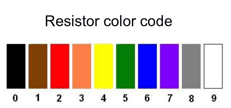


4 2014 UK-electronic Color table for resistors MF207 FTE52 1% and a example
5 Bill of material Quantity Description Resistors 1 22R (red/red/black/gold/brown) 1 1K (brown/black/black/brown/brown) 1 2K2 (red/red/black/brown/brown) 1 5K1 (green/brown/black/black/brown) 3 10K (brown/black/black/red/brown) 1 20K (red/black/black/red/brown) 1 22K (red/red/black/red/brown) 2 100K (brown/black/black/orange/brown) 1 200K (red/black/black/orange/brown) 1 2M2 (red/red/black/yellow/brown) 1 Trim pot CA6V 10K Capacitors 1 Ceramic capacitor 47pF (47) 1 Ceramic capacitor 100pF (101) 1 MKT 0.022µF = 22nF (223) 2 MKT 1µF = 1000nF (105) 1 Elektrolytic capacitor RASM 47µF/16V 1 Elektrolytic capacitor RASM 100µF/16V 1 Elektrolytic capacitor RA 220µF/ 10V Diodes 1 Shottky-Diode 1N5718 or 5718 (Cathode = line) 1 LED 3mm Red Low current Schaltkreise 1 Reverb Modul Belton BTDR-2-X (your choose) 1 Voltage regulator 78L05-5V/100mA 1 Dual OPV TL072 Potentiometer 1 16mm Potentiometer 50K-B (linear) Reverb Mechanic 1 Printboard Miniverb V2 DKL 2 Audio jack PCB-version (Mono- Output/Stereo- Input) 1 3PDT Switch Standard SL 1 DC-jack ROKA isolated pcb-version 1 LED spacer 22mm 1 Some coloured wire/ isolated hose/ heat shrink 1 Battery connector soft 1 Socket LC 08 Soldering tin is not part of delivery 2015 UK-electronic
. Left are the names of the components, on the right picture the values.")
6 Soldering the Printboard Back to the top you should start with the lowest components to be fitted, ie first, the resistors then the capacitors. In the next level then the IC sockets, the voltage regulator. The BTDR-2 module at the last (component side). Left are the names of the components, on the right picture the values. One should make things quiet and rather even look because it is not as easy for inexperienced to switch to a through-hole printed circuit board, a component. If everything is assembled and the potentiometer wired, they are soldered into the PCB only a. Thus, the majority would already be done. Who has opted for a pre-drilled housing needs now just mount the Potentimeter and place the board about it. When the board you have to press a bit, and before the strands sort something neatly under the board, since it at the point where the dual potentiometer sits but is relatively scarce. In any case, the board must sit so that when you screw the peripheral groove does not touch any pins on the board UK-electronic

7 2015 UK-electronic

8 2014 UK-electronic The following drill diameter should be used: Potentiometer: 7 to 8mm Jacks: 11mm 3PDT switch 13 to 14mm, making it possible to better fit the board if the holes of the jack bushes not agree 100%. DC jack: 10mm LED: 3mm As knobs which are used for 6.35mm shaft with set screw. The trimmer potentiometer (10K) is used to balance the volume between the original signal and reverberated signal. Through the hole in the board is accessible after installation of the board with a small Phillips screwdriver. The holes for the jacks are 12mm 11mm from the bottom edge, the DC jack. The distance phone jack DC jack is 18.5mm. Technical design subject changes! 2015 UK-electronic
9 - + TN T RN R SN S A2 A1 A3 E A B2 C1 C3 B1 B3 TN C2 T RN R SN S S IN OUT1 OUT PGND +5V 1 4 SGND
10
11
High Power (15W + 15W) Stereo Amplifier
 Stereo Amplifier") High Power (15W + 15W) Stereo Amplifier Build Instructions Issue 1.0 Build Instructions Before you put any components in the board or pick up the soldering iron, just take a look at the Printed Circuit
High Power (15W + 15W) Stereo Amplifier Build Instructions Issue 1.0 Build Instructions Before you put any components in the board or pick up the soldering iron, just take a look at the Printed Circuit
DELUXE STEREO AMPLIFIER KIT
 ESSENTIAL INFORMATION BUILD INSTRUCTIONS CHECKING YOUR PCB & FAULT-FINDING MECHANICAL DETAILS HOW THE KIT WORKS CREATE YOUR OWN SPEAKER DOCK WITH THIS DELUXE STEREO AMPLIFIER KIT Version 2.0 Build Instructions
Installation/assembly manual for DCC/Power shield
 Installation/assembly manual for DCC/Power shield The DCC circuit consists of the following components: R1/R6 R2/R3 R4/R5 D1 C2 2 kω resistor ½ Watt (colour code Red/Black/Black/Brown/Brown) 10 kω resistor
TEMPEST PROJECT NAME. BASED ON Friedman BE-OD / Dirty Shirley. BUILD DIFFICULTY Intermediate. DOCUMENT VERSION Amp-Like Distortion 1.0.
 PROJECT NAME TEMPEST BASED ON Friedman BE-OD / Dirty Shirley BUILD DIFFICULTY Intermediate EFFECT TYPE DOCUMENT VERSION Amp-Like Distortion.0. (09-0-08) PROJECT SUMMARY A pedal recreation of the Friedman
MP3 audio amplifier. Build Instructions. Issue 2.0
 MP3 audio amplifier Build Instructions Issue 2.0 Build Instructions Before you put any components in the board or pick up the soldering iron, just take a look at the Printed Circuit Board (PCB). The components
Insert the male, 90 angled, 2x10 connectors into the corresponding 2x10 sockets and put them in place, flat under the PCB. Solder.
 MC624 Assembly guide Safety warning The kits are main powered and use potentially lethal voltages. Under no circumstance should someone undertake the realisation of a kit unless he has full knowledge about
STAGE INTERCOM KIT 1.1 SPECIFICATION. General: The lower section is a small power amplifier designed to drive headphones or a small 8ohm speaker.
 STAGE INTERCOM KIT Version 2.1.1 - March 2018 - EduTek Ltd 1.0 DESCRIPTION This intercom module comprises of two separate circuits sharing the same supply. The upper section is a pre-amplifier designed
Effects Loop Installation Guide
 Warnings and Disclaimer Effects Loop Installation Guide You will be working with HIGH VOLTAGE. These voltages CAN BE DEADLY if you are not extremely careful. If you are not comfortable working with HIGH
Pacific Antenna Two Tone Generator
 Pacific Antenna Two Tone Generator Description Our Two Tone Generator kit provides two non-harmonic, sine wave signals for testing audio circuits Outputs of approximately 700Hz and 1900Hz and the combination
Electronics Construction Manual
 Electronics Construction Manual MitchElectronics 2018 Version 1 07/05/2018 www.mitchelectronics.co.uk CONTENTS Introduction 3 How To Solder 4 Resistors 5 Capacitors 6 Diodes and LEDs 7 Switches 8 Transistors
De-Generator DIY sample Synthesizer
 De-Generator DIY sample Synthesizer Building instruction 3, the filterboard V 1.03 english Date 10.09.2018 www.tubeohm.com Hello, now we come to the third building instruction. In this manual we will assemble
CP5176 Assembly guide. Soldering. CP5176 Assembly guide Main PCB PCB split. Document revision 2.1 Last modification : 12/11/17
 CP5176 Assembly guide Safety warning The kits are main powered and use potentially lethal voltages. Under no circumstance should someone undertake the realisation of a kit unless he has full knowledge
PROJECT SUMMARY A flexible drive pedal that can go from clean volume boost to smooth overdrive. Includes a 2-band tone stack for treble & bass.
 PROJECT NAME PERELANDRA BASED ON Xotic BB Preamp BUILD DIFFICULTY Easy EFFECT TYPE DOCUMENT VERSION Boost / Overdrive.0.0 (08-09-) PROJECT SUMMARY A flexible drive pedal that can go from clean volume boost
Mini B lue M idnight
 Mini Blue Midnight 2011 by Shattered Glass Audio. All rights reserved. No part of this document may be reproduced or transmitted in any form or by any means, electronic, mechanical, photocopying, recording,
Noise Gate A noise reduction stomp box
 Noise Gate A noise reduction stomp box The Noise Gate (NG) is a pedal for noise reduction. However, unlike other filters that changes how the instrument sounds, the Noise Gate blocks the noise when the
PicoTurbine Mark 8.3 Generator Field Controller Kit
 PicoTurbine Mark 8.3 Generator Field Controller Kit Based on a design published in Home Power magazine by Richard Perez. Used with permission. Reprint of original article included with kit. An easy-to-build
Electronics Construction Manual
 Electronics Construction Manual MitchElectronics 2019 Version 3 04/02/2019 www.mitchelectronics.co.uk CONTENTS Introduction 3 How To Solder 4 Resistors 5 Capacitors 6 Diodes and LEDs 7 Switches 8 Transistors
LED Knight Rider. Yanbu College of Applied Technology. Project Description
 LED Knight Rider Yanbu College of Applied Technology Project Description This simple circuit functions as a 12 LED chaser. A single illuminated LED 'walks' left and right in a repeating sequence, similar
UF-3701 Power Board Construction Guide
 Page 1/5 Soldering and Part Placement See the Chapter 3 of the MIT 6270 Manual for information on electronic assembly, including soldering techniques and component mounting. Construction Information All
TKEY-1. CW touch key. (no electromechanical contacts) Assembly manual. Last update: June 20,
 Assembly manual. Last update: June 20,") TKEY-1 CW touch key (no electromechanical contacts) Assembly manual Last update: June 20, 2017 ea3gcy@gmail.com Updates and news at: www.ea3gcy.com Thanks for constructing the TKEY-1A CW touch key Have
TKEY-1 CW touch key (no electromechanical contacts) Assembly manual Last update: June 20, 2017 ea3gcy@gmail.com Updates and news at: www.ea3gcy.com Thanks for constructing the TKEY-1A CW touch key Have
Have Mercy Building instructions v1.1
 Have Mercy Building instructions v1.1 Table of contents Have Mercy v1.1 PCB layout... 3 Components... 4 Power section... 5 Build sequence... 5 Calibration... 6 Off board wiring... 6 Potentiometers... 6
TuBbika SMR-4-PLUS voicecard
 TuBbika SMR-4-PLUS voicecard Assembly instructions We assume you know soldering. If you don t, look first at this tutorial. Be patient! And if you have any doubt, head to the forum never be afraid to ask!
You need the following components to assemble the Black n Wood Nixie Clock circuit board:
 You need the following components to assemble the Black n Wood Nixie Clock circuit board: Quantity Designator Description 1 Battery Battery, CR1220 1 Battery Battery holder 3 Button 1, Button 2, Button
Dual LPG + Timbre RANDOM*SOURCE. Dual LPG / Timbre RANDOMSOURCE.NET
 Dual LPG + Timbre The Dual LPG + Timbre section is part of the Donks module and comprises a dual low pass gate based on the famous 292C as well as the equally famous Timbre circuit adjusted to +12V and
PROJECT SUMMARY A flexible drive pedal that can go from clean volume boost to smooth overdrive. Includes a 2-band tone stack for treble & bass.
 PROJECT NAME MALACANDRA BASED ON Xotic BB Preamp BUILD DIFFICULTY Easy EFFECT TYPE DOCUMENT VERSION Boost / Overdrive 1.0.0 (2018-09-22) PROJECT SUMMARY A flexible drive pedal that can go from clean volume
K8099 NIXIE CLOCK. * optional enclosure TKOK19 (black) - TKOK17 (white) ** optional plexiglass enlcosure B8099 ILLUSTRATED ASSEMBLY MANUAL
 - TKOK17 (white) ** optional plexiglass enlcosure B8099 ILLUSTRATED ASSEMBLY MANUAL") Total solder points: 230 + 74 Difficulty level: beginner 1 2 3 4 5 advanced NIXIE CLOCK K8099 ** * A unique combination of both vintage and modern electronics ILLUSTRATED ASSEMBLY MANUAL H8099IP-1 * optional
Total solder points: 230 + 74 Difficulty level: beginner 1 2 3 4 5 advanced NIXIE CLOCK K8099 ** * A unique combination of both vintage and modern electronics ILLUSTRATED ASSEMBLY MANUAL H8099IP-1 * optional
EchoBlue Delay. PT2399 Delayayayayayay v3.0
 EchoBlue Delay PT2399 Delayayayayayay v3.0 Contents of this document are 2015 Pedal Parts Ltd. No reproduction permitted without the express written permission of Pedal Parts Ltd. All rights reserved.
Total solder points: 240 Difficulty level: beginner advanced LIGHT COMPUTER K5201 ILLUSTRATED ASSEMBLY MANUAL
 Total solder points: 240 Difficulty level: beginner 1 2 3 4 5 advanced LIGHT COMPUTER K5201 16 different patterns and 7 outputs provide a unique light show. ILLUSTRATED ASSEMBLY MANUAL H5201IP-1 Features
MAIN PCB (The small one)
") THANKS FOR CHOOSING ONE OF OUR KITS! This manual has been written taking into account the common issues that we often find people experience in our workshops. The order in which the components are placed
THANKS FOR CHOOSING ONE OF OUR KITS! This manual has been written taking into account the common issues that we often find people experience in our workshops. The order in which the components are placed
solutions for teaching and learning
 RKP18Motor Component List and Instructions PCB layout Constructed PCB Schematic Diagram RKP18Motor Project PCB Page 1 Description The RKP18Motor project PCB has been designed to use PIC microcontrollers
Schematic Diagram: R2,R3,R4,R7 are ¼ Watt; R5,R6 are 220 Ohm ½ Watt (or two 470 Ohm ¼ Watt in parallel)
") Nano DDS VFO Rev_2 Assembly Manual Farrukh Zia, K2ZIA, 2016_0130 Featured in ARRL QST March 2016 Issue Nano DDS VFO is a modification of the original VFO design in Arduino Projects for Amateur Radio by
Nano DDS VFO Rev_2 Assembly Manual Farrukh Zia, K2ZIA, 2016_0130 Featured in ARRL QST March 2016 Issue Nano DDS VFO is a modification of the original VFO design in Arduino Projects for Amateur Radio by
HARDWARE OPERATIONS MANUAL
 HARDWARE OPERATIONS MANUAL Table of Contents INTRODUCTION... 2 SECTION 1: HARDWARE COMPONENT ASSEMBLIES... 2 MECHANICAL HARDWARE AND CASE... 2 PCB ASSEMBLY... 4 ISD RECORDING CIRCUIT... 5 BREADBOARD ASSEMBLY...
EQ573 Assembly guide. EQ573 Assembly guide Main board 1. Diodes. 2. Resistors (1) 3. Test pins. 4. Ceramic capacitors.
 3. Test pins. 4. Ceramic capacitors.") EQ573 Assembly guide Safety warning The kits are main powered and use potentially lethal voltages. Under no circumstance should someone undertake the realisation of a kit unless he has full knowledge about
EQ573 Assembly guide Safety warning The kits are main powered and use potentially lethal voltages. Under no circumstance should someone undertake the realisation of a kit unless he has full knowledge about
Solder the Harlequin, Revision F, March Solder the Harlequin - please read carefully (also the addendum!) before starting
 before starting") Solder the Harlequin, Revision F, March 2014 Page 1 of 8 Solder the Harlequin - please read carefully (also the addendum!) before starting You should check the kit for completeness (see addendum). If you
Solder the Harlequin, Revision F, March 2014 Page 1 of 8 Solder the Harlequin - please read carefully (also the addendum!) before starting You should check the kit for completeness (see addendum). If you
Noise Source Model 9751 Assembly and Using Manual
 Noise Source Model 9751 Assembly and Using Manual This second-generation 9700-series processing element for modular sound synthesizers is designed to provide great sound and excellent value. This module
Assembly Instructions for the KA Electronics IGFO Input Gain Filter Output Board
 Assembly Instructions for the KA Electronics IGFO Input Gain Filter Output Board IGFO PC Board Stuffing Guide Install IC sockets Place the PC Board on the work bench silkscreen side face up. Place ten
MONAD PROJECT NAME. BASED ON Univox Uni-Drive UD-50. BUILD DIFFICULTY Beginner. DOCUMENT VERSION Boost ( ) EFFECT TYPE
 EFFECT TYPE") PROJECT NAME MONAD BASED ON Univox Uni-Drive UD-50 BUILD DIFFICULTY Beginner EFFECT TYPE DOCUMENT VERSION Boost 1.0.0 (2018-12-15) PROJECT SUMMARY A basic 3-transistor booster that gets some grit at higher
PROJECT NAME MONAD BASED ON Univox Uni-Drive UD-50 BUILD DIFFICULTY Beginner EFFECT TYPE DOCUMENT VERSION Boost 1.0.0 (2018-12-15) PROJECT SUMMARY A basic 3-transistor booster that gets some grit at higher
PROJECT SUMMARY A reproduction of a rare and very expensive low-to-mid-gain overdrive with 3-band EQ that is popular in the Nashville scene.
 PROJECT NAME QUANTUM BASED ON Ibanez MT-0 Mostortion BUILD DIFFICULTY Easy EFFECT TYPE DOCUMENT VERSION Overdrive / Distortion.0.0 (08--5) PROJECT SUMMARY A reproduction of a rare and very expensive low-to-mid-gain
Deep Vibes. Wobbly Optical Vibe action
 Deep Vibes Wobbly Optical Vibe action Contents of this document are 2018 Pedal Parts Ltd. No reproduction permitted without the express written permission of Pedal Parts Ltd. All rights reserved. Important
KDR00101 DMX Controlled Relay Kit
 KDR00101 DMX Controlled Relay Kit This is a DMX512-A relay kit using ANSI approved RJ-45 connectors for DMX networks. Power requirements are 12 Vdc @ 100 ma. The relay contact rating is 10 Amp @ 120 or
Build Your Own Clone Optical Compressor Kit Instructions
 Build Your Own Clone Optical Compressor Kit Instructions Warranty: BYOC, LLC guarantees that your kit will be complete and that all parts and components will arrive as described, functioning and free of
アナログ. D/500 FET Limiter PCB Overlay, Schematic and Bill of Materials mnats
 アナログ D/500 FET Limiter PCB Overlay, Schematic and Bill of Materials 2014 mnats LED1 LED2 Q1_ALT Q11_ALT R23 IC1 R55 R56 GR SIG +VR -VR -V IN VU SIG 0 ADJ Q6 ST LNK SW1 SW3 R21 R61 R4 R5 R7 R10 R6 R8 C1
RKP08 Component List and Instructions
 RKP08 Component List and Instructions PCB layout Constructed PCB RKP08 Scematic RKP08 Project PCB Page 1 Description The RKP08 project PCB has been designed to use PIC microcontrollers such as the Genie
Universal Keying Adapter 3+
 Universal Keying Adapter 3+ The Universal Keying Adapter Version 3+ kit will allow you to key nearly any transmitter or transceiver with a straight key, electronic keyer, computer serial or parallel port
Content. Centura DIY Kit Instructions
 Centura DIY Kit Instructions 2017 Ceriatone Amplification http://www.ceriatone.com/ nik@ceriatone.com - for ordering purpose kilopp@hotmail.com - backup email address Content 1. Introduction 2. Schematic
STRATUS PROJECT NAME. BASED ON Ibanez TS-9 Tube Screamer. BUILD DIFFICULTY Easy. DOCUMENT VERSION Overdrive ( ) EFFECT TYPE
 EFFECT TYPE") PROJECT NAME STRATUS BASED ON Ibanez TS-9 Tube Screamer BUILD DIFFICULTY Easy EFFECT TYPE DOCUMENT VERSION Overdrive 1.0.0 (018-09-) PROJECT SUMMARY The quintessential mid-hump overdrive pedal made famous
PROJECT NAME STRATUS BASED ON Ibanez TS-9 Tube Screamer BUILD DIFFICULTY Easy EFFECT TYPE DOCUMENT VERSION Overdrive 1.0.0 (018-09-) PROJECT SUMMARY The quintessential mid-hump overdrive pedal made famous
MAIN PCB (The small one with the square cut out from one side)
") THANKS FOR CHOOSING ONE OF OUR KITS! This manual has been written taking into account the common issues that we often find people experience in our workshops. The order in which the components are placed
THANKS FOR CHOOSING ONE OF OUR KITS! This manual has been written taking into account the common issues that we often find people experience in our workshops. The order in which the components are placed
The Sudden Storm Kit. by QRPme. Builder s Guide. version4.2. for. Sudden Storm ][ Ver4 (red pcb) Updated 01/10/2012
![The Sudden Storm Kit. by QRPme. Builder s Guide. version4.2. for. Sudden Storm ][ Ver4 (red pcb) Updated 01/10/2012](/thumbs/75/72448638.jpg "The Sudden Storm Kit. by QRPme. Builder s Guide. version4.2. for. Sudden Storm ][ Ver4 (red pcb) Updated 01/10/2012") The Sudden Storm Kit by QRPme Builder s Guide version4.2 for Sudden Storm ][ Ver4 (red pcb) Updated 01/10/2012 Open the can and the adventure begins 1 Organize the parts and take an inventory Bill of Materials
The Sudden Storm Kit by QRPme Builder s Guide version4.2 for Sudden Storm ][ Ver4 (red pcb) Updated 01/10/2012 Open the can and the adventure begins 1 Organize the parts and take an inventory Bill of Materials
KDR00301 DMX Controlled Relay Kit
 KDR00301 DMX Controlled Relay Kit This is a DMX512-A relay kit using ANSI approved RJ-45 connectors for DMX networks. Power requirements are 12 Vdc @ 200 ma. The relay contact rating is 10 Amp @ 120 or
IC-I AND IC-I F GENERAL DESCRIPTION SPECIFICATIONS. Output Impedance: Phones: 60 ohms (Unit is designed for use with ohm phones.
 IC-I AND IC-I F GENERAL DESCRIPTION The IC-1 and IC-1 F are single-channel, singleline intercom stations designed for use with dynamic headsets. The IC-1 is a compact, lightweight unit which may be worn
Assembly Instructions for the KA Electronics Elliptic Equalizer
 Assembly Instructions for the KA Electronics Elliptic Equalizer Install IC sockets Elliptic Equalizer PC Board Stuffing Guide Place the PC Board on the work bench silkscreen side face up. Place twelve
XYLOPHONE KIT ESSENTIAL INFORMATION. Version 2.0 CREATE YOUR OWN ELECTRONIC MUSICAL INTRUMENT WITH THIS
 ESSENTIAL INFORMATION BUILD INSTRUCTIONS CHECKING YOUR PCB & FAULT-FINDING MECHANICAL DETAILS HOW THE KIT WORKS CREATE YOUR OWN ELECTRONIC MUSICAL INTRUMENT WITH THIS XYLOPHONE KIT Version 2.0 Build Instructions
Quicksilver 606 TR-606 CPU Upgrade
 Quicksilver 606 TR-606 CPU Upgrade D650C 128 Installation Guide Social Entropy Electronic Music Instruments TABLE OF CONTENTS WARNINGS... 1 OVERVIEW... 2 WHAT'S IN THE BOX... 3 OPENING THE TR-606 CASE...
Tubbutec Sumtiple Kit Version Construction Manual
 Tubbutec Sumtiple Kit Version Construction Manual This document describes the construction of the Sumtiple Kit. The following parts are included: 1x Sumtiple PCB with SMD-Parts already soldered 1x Front
GuitarPCB.com Mini-Me Chorus Build Instructions
 GuitarPCB.com Mini-Me Chorus Build Instructions This compares to the popular Small Clone TM chorus, but includes modifications. The major difference between this circuit and the commercial pedal on which
Assembly Instructions IV-11 DCF, melody
 This IV-11 clock is the next generation to the IV-11 Quartz, DCF, melody. This is not a beginner kit. It requires soldering experience on the IV-18 and the IV-3A board The switching power supply wall adapter
5U Oakley Modular Series. Multimix issue 5 Four channel mixer with reversible attenuators
 Oakley Sound Systems 5U Oakley Modular Series Multimix issue 5 Four channel mixer with reversible attenuators Builder's Guide V5.1 Tony Allgood Oakley Sound Systems CARLISLE United Kingdom Introduction
GENERAL DESCRIPTION SPECIFICATIONS. output Impedance: Phones: 60 ohms (Designed for use with ohm phones.)
") GENERAL DESCRIPTION The IC-S is a single-channel speaker station designed for use with an external microphone. There are four versions of the IC-S; all identified by the same model name, but distinguished
GENERAL DESCRIPTION The IC-S is a single-channel speaker station designed for use with an external microphone. There are four versions of the IC-S; all identified by the same model name, but distinguished
Super Skwisher. Ross Compressor +++
 Super Skwisher Ross Compressor +++ Contents of this document are 2015 Pedal Parts Ltd. No reproduction permitted without the express written permission of Pedal Parts Ltd. All rights reserved. Important
B.Y.O.C. MK2 Kit Instructions
 B.Y.O.C. MK2 Kit Instructions Parts Checklist.....page 2 Populating the Circuit Board......page 3-5 Assembly......page 6 Wiring......page 7 Installing the LED and Mounting the PCB...page 8-9 Finish up...page
These are the illustrated step-by-step guidelines for upgrading your Quad 306 with the Dada Electronics upgrade-kit.
 Quad 306 DIY illustrated guidelines version 1.1 These are the illustrated step-by-step guidelines for upgrading your Quad 306 with the Dada Electronics upgrade-kit. We will replace all electrolytic capacitors,
1. Mount the echo and tremolo control switches under the keyboard shelf, in a position convenient for the organist.
 CONSOLE CONNECTOR KIT 8101 INSTALLATION INSTRUCTIONS FOR USE WITH: HAMMOND Organ Models A-100, D-100, RT2, RT3 LESLIE Speaker Models 122, 122RV KIT CONTENT Console Connector Assembly 047357 Echo Control
ME 3210: Mechatronics Signal Conditioning Circuit for IR Sensors March 27, 2003
 ME 3210: Mechatronics Signal Conditioning Circuit for IR Sensors March 27, 2003 This manual and the circuit described have been brought to you by Adam Blankespoor, Roy Merril, and the number 47. The Problem:
QUANTOM DEFRAKULATOR Build Document last updated june 2018 for PCB version 1.0
 QUANTOM DEFRAKULATOR Build Document last updated june 2018 for PCB version 1.0 The Quantom Defrakulator is a drone synthesizer with 3 square wave oscillators and one LFO (low frequency oscillator). Each
KDS Channel DMX Controlled Servo Kit
 KDS00801 8-Channel DMX Controlled Servo Kit This is a DMX512-A controlled servo kit using ANSI approved RJ-45 connectors for DMX networks. Power requirements are 8-20 VDC @ 50 ma. The board features an
CV Arpeggiator Rev 2 Build Documentation.
 CV Arpeggiator Rev Build Documentation. Last updated 8-0-03 The CV Arpeggiator is a modular synth project used for creating arpeggios of control voltage. It utilizes a custom programmed PIC 6F685 micro
Building the VMW Time Circuitry Meter by Vincent M. Weaver 6 May 2014
 Building the VMW Time Circuitry Meter http://www.deater.net/weave/vmwprod/hardware/time_circuit/ by Vincent M. Weaver 6 May 2014 1 Introduction This is a work in progress. I will update it as I complete
QRPometer Assembly Manual Copyright 2012 David Cripe NM0S The 4 State QRP Group. Introduction
 QRPometer Assembly Manual Copyright 2012 David Cripe NM0S The 4 State QRP Group Introduction Thank you for purchasing a QRPometer. We hope you will enjoy building it and and find it a useful addition to
The CW Machine Hardware
 The CW Machine Hardware 2010 Ulrich H. Steinberg Contents Introduction...2 Connecting the Hardware...3 The Configuration Switches...5 Power Considerations...7 Serial Communication...8 Installing the USB-Serial
Installation instructions DC Protection and Delay unit, Version 1.2 The package should contain: A piece of normal gauge yellow wire for the AC connect
 Installation instructions DC Protection and Delay unit, Version 1.2 How does the unit work? Delay: Basically a capacitor is charged via a resistor, when the voltage of the capacitor reach a certain level,
Snail Gear Building instructions V1.0
 Snail Gear Building instructions V1.0 Table of contents Components... 3 PCB layout... 4 General guideline for components... 5 General building tips... 5 Modifications... 6 Biasing... 7 Off board wiring...
HALO. Easy. Distortion / Sustainer, Fuzz ( )
") PROJECT NAME HALO BASED ON Electro-Harmonix Big Muff Pi BUILD DIFFICULTY Easy EFFECT TYPE DOCUMENT VERSION Distortion / Sustainer, Fuzz 1.0.0 (2018-07-04) PROJECT SUMMARY One of the most classic guitar
PROJECT NAME HALO BASED ON Electro-Harmonix Big Muff Pi BUILD DIFFICULTY Easy EFFECT TYPE DOCUMENT VERSION Distortion / Sustainer, Fuzz 1.0.0 (2018-07-04) PROJECT SUMMARY One of the most classic guitar
Assembly Instructions (8/14/2014) Your kit should contain the following items. If you find a part missing, please contact NeoLoch for a replacement.
 Your kit should contain the following items. If you find a part missing, please contact NeoLoch for a replacement.") NeoLoch NLT-28P-LCD-5S Assembly Instructions (8/14/2014) Your kit should contain the following items. If you find a part missing, please contact NeoLoch for a replacement. Kit contents: 1 Printed circuit
NeoLoch NLT-28P-LCD-5S Assembly Instructions (8/14/2014) Your kit should contain the following items. If you find a part missing, please contact NeoLoch for a replacement. Kit contents: 1 Printed circuit
Assembly Guide. LEDs. With these assembly instructions, you can easily build your own SWT16. All required components are included in this kit.
 Assembly Guide With these assembly instructions, you can easily build your own SWT16. All required components are included in this kit. You need the following tools: soldering iron, wire cutter and solder.
3 pyro output datalogger altimeter with an ATmega 328 microcontroller Kit assembly instructions
 3 pyro output datalogger altimeter with an ATmega 328 microcontroller Kit assembly instructions Version date Author Comments 1.0 29/05/2013 Boris du Reau Initial version Rocket Type Micro-max Model Mid
Touch Sense Controller
 Touch Sense Controller Paul Boston May 11, 2011 (Modified May 22, 2014) (Modified Dec 28, 2015) The Touch Sense Controller is a microprocessor-controlled circuit designed to provide a switch closure when
Cumbria Designs T-1. C-1 Controller. User Manual
 Cumbria Designs T-1 C-1 Controller User Manual CONTENTS 1 INTRODUCTION 2 2 CIRCUIT DESCRIPTION 2 3 ASSEMBLY 3 4 CONNECTIONS AND CONFIGURATION 4 5 TESTING 6 Appendix A C-1 Circuit Diagram and PCB Component
4.0 Blue LED DCF77 Clock documentation
 4.0 Blue LED DCF77 Clock documentation 1. LED Clock Main Board PCB mounting: Mount and solder the eight wire bridges. Mount and solder resistors R16, R18, R20, R22. Mount and solder capacitors C1 C3 (pitch
Audio Restoration Project: Repair Source Selector Switch and Upgrade Arcam Alpha 9 Integrated Power Amplifier.
 Audio Restoration Project: Repair Source Selector Switch and Upgrade Arcam Alpha 9 Integrated Power Amplifier. This classic was available in 2 forms the Integrated Amplifier, and the Power Amplifier. Although
Sierra Radio Systems. Making a Keyer with the. HamStack. Project Platform
 Sierra Radio Systems Making a Keyer with the HamStack Project Platform Introduction The HamStack Project Board includes primary interface elements needed to make a high quality CW keyer. Using the LCD
solutions for teaching and learning
 RKAmp3 Component List and Instructions PCB layout Constructed PCB Schematic RKAmp3 Stereo Amplifier Page 1 Description The RKAmp3 stereo amplifier PCB has been designed around the 2 x 7watt stereo amplifier
RECORD & PLAYBACK KIT
 ESSENTIAL INFORMATION BUILD INSTRUCTIONS CHECKING YOUR PCB & FAULT-FINDING MECHANICAL DETAILS HOW THE KIT WORKS ADD AN AUDIO MESSAGE TO YOUR PRODUCT WITH THIS RECORD & PLAYBACK KIT Version 2.1 Build Instructions
ARES 2 Tone Sequential Tone Decoder Kit Assembly Instructions
 Tools Required: ARES Tone Sequential Tone Decoder Kit Assembly nstructions 3/8 Electric Drill Soldering ron Wire Strippers Needle Nose Pliers Wire Cutters Ruler 60/40 Solder Phillips Screw Driver /8, 5/64,
GRAVITON. Intermediate. Metal Distortion ( )
") PROJECT NAME GRAVITON BASED ON BOSS HM- Heavy Metal BUILD DIFFICULTY Intermediate EFFECT TYPE DOCUMENT VERSION Metal Distortion.0.0 (08-07-04) PROJECT SUMMARY A unique distortion effect favored by extreme
PROJECT NAME GRAVITON BASED ON BOSS HM- Heavy Metal BUILD DIFFICULTY Intermediate EFFECT TYPE DOCUMENT VERSION Metal Distortion.0.0 (08-07-04) PROJECT SUMMARY A unique distortion effect favored by extreme
solutions for teaching and learning
 RKAmp1 Component List and Instructions PCB layout Constructed PCB Schematic RKAmp1 Stereo Amplifier Page 1 Description The RKAmp1 stereo amplifier PCB has been designed around the 2 x 1watt stereo amplifier
DTMF Device/ Relay Remote Controller
 DTMF Device/ Relay Remote Controller This high quality board is designed to get DTMF input from Internet / Mobile / Wireless receivers/ Computer for operation of 4 relays. AC 250 V AC rated Relays can
Assembly Instructions for the KA Electronics RIAA EQ Monitor Switcher
 Assembly Instructions for the KA Electronics RIAA EQ Monitor Switcher Install IC sockets EQ Monitor Switcher PC Board Stuffing Guide Place the PC Board on the bench silkscreen side face up. Drop eleven
KAA Watt x 2 Class-D Audio Amplifier Kit
 KAA10021 50 Watt x 2 Class-D Audio Amplifier Kit This amplifier kit uses Texas Instruments TPA3116D2 stereo audio amplifier IC for driving speakers up to 50 watts @ 4 ohm per channel in stereo mode and
Sierra Radio Systems. HamStack. Project Board Reference Manual V1.0
 Sierra Radio Systems HamStack Project Board Reference Manual V1.0 Welcome HamStack Project Board Reference Manual Revision 1.0.3 2011 George Zafiropoulos, KJ6VU and John Best, KJ6K This guide provides
nonlinearcircuits giant B0N0 build & BOM VERS2
 nonlinearcircuits giant B0N0 build & BOM VERS2 This module has its roots in the NLC DelayNoMore and Vactrol PiLL. It was partly inspired from reading several research articles on chaos in PLL circuits.
Evaluate: MAX14589E/MAX14594E/ MAX MAX14589E/MAX14594E/ MAX14689 Evaluation Kits. Features and Benefits. General Description.
 Evaluation Kits General Description The MAX14589E/MAX14594E/ evaluation kits (EV kits) are fully assembled and tested circuit boards that demonstrate the functionality of the MAX14589E, MAX14594E, and
Dwarf Boards. DB021 : L298 dual motor driver
 Dwarf Boards DB021 : L298 dual motor driver (c) Van Ooijen Technische Informatica version 1.0 PICmicro, In-Circuit Serial Programming and ICSP are registerd trademarks of Microchip Technology Inc. Introduction
PROJECT SUMMARY A classic untamed fuzz from the 1970s that adds an octave-up overtone, famous for its use by Pete Townshend of The Who.
 PROJECT NAME RIFT BASED ON Univox Superfuzz BUILD DIFFICULTY Intermediate EFFECT TYPE DOCUMENT VERSION Octave Fuzz 1.0.0 (2019-02-01) PROJECT SUMMARY A classic untamed fuzz from the 1970s that adds an
Number Name Description Notes Image 0101 Resistor, 100 ohm. brown-black-browngold. ¼ watt, 5% tolerance, red-red-brown-gold. brown-black-red-gold.
 Passive Components 0101 Resistor, 100 brown-black-browngold. 690620 0102 Resistor, 220 red-red-brown-gold. 690700 0103 Resistor, 1000 brown-black-red-gold. 690865 0104 Resistor, 10k 0201 Capacitor, 1 µf,
R e v. I - 4, N o v e m b e r 2 7,
 K2 OWNER S MANUAL ERRATA R e v. I - 4, N o v e m b e r 2 7, 2 0 1 5 M A K E T H E S E C H A N G E S T O Y O U R R E V. I M A N U A L B E F O R E Y O U B E G I N A S S E M B L Y 1. Page 20, Right Column,
PowerAmp Design EVAL117 EVALUATION KIT FOR PAD117A
 EVALUATION KIT FOR PAD117A INTRODUCTION The EVAL117 evaluation kit provides a convenient method to become familiar with the operation of the PAD117A operational amplifier before your application circuit
K2 OWNER S MANUAL ERRATA. Rev. I - 7, March 19, 2017
 K2 OWNER S MANUAL ERRATA Rev. I - 7, March 19, 2017 MAKE THESE CHANGES TO YOUR REV. I MANUAL BEFORE YOU BEGIN ASSEMBLY OR ANNOTATE THE MANUAL TO REFER TO THIS ERRATA. 1. Page 20, Right Column: Under Inventory,
Microsystems. SCI-6 Sound Card Interface Kit Version 1.09 January 2015
 UM Unified Microsystems SCI-6 Sound Card Interface Kit Version 1.09 January 2015 The SCI-6 interface was designed to be a low cost, high quality interface between your PC s sound card and radio transceiver.
RC-210 Repeater Controller Assembly Manual
 Arcom Communications 24035 NE Butteville Rd Aurora, Oregon 97002 (503) 678-6182 arcom@ah6le.net RC-210 Repeater Controller Assembly Manual Hardware Version 3.0 Original Release Date September 13, 2004
dual bipolar voltage controlled step sequencer DIY ASSEMBLY MANUAL v1.03
 dual bipolar voltage controlled step sequencer DIY ASSEMBLY MANUAL v1.03 Contents Contents... 2 Introduction... 3 Part Sourcing Notes for Non Kit Builders... 3 Eurorack Kit Assembly... 4 Resistors and