User Manual. Paperless Recorder VR18
|
|
|
- Austen Pierce
- 6 years ago
- Views:
Transcription

1 User Manual Paperless Recorder VR18 Future Design Controls, Inc West 98 th Place Bridgeview, IL Office: Fax Technical Support VR18 Manual v2.37 November 2011 FDC-UMVR181R
2 Contents Page Safety Safety Symbols Safety Notes and Precautions Static Electricity General Description Unique Features of Recorder Expandable Input and Output cards Communication Storage Media CF card Data Security Infrared Detector Ordering Codes and Accessories Specifications Installation and wiring Unpacking Installation Setup Input, Output & 24VDC power supply cards Wiring of the cards RS-232, RS-422, RS-485 wiring Installation of Compact Flash CF Card Basic Operation Page Mode History Event Status Exit Dump Clear Operate Shutdown Logout Small Icons Configuration Channel (Analog input, Digital input, Analog output, Math input) Display Tools (Timer, Counter & Totalizer) Instrument Clock Normal Security & High Security with CFR-21 part 11 type features FDC-VR18_Manual_V2.37_November-2011.doc 2
3 4.7 Demo System Info Configuration Example PC software and Communication configuration Observer I & Observer II PC software guide Ethernet Configuration RS 232, RS485, RS422 Configuration CF card Configuration Configuration in Real-Time Viewer DDE dynamic data exchange Application examples Trouble shooting FAQs frequently asked questions FDC-VR18_Manual_V2.37_November-2011.doc 3
4 Safety This recorder is compliant with the requirements of: CE: EN UL: 61010C-1 CSA: C22.2 No file # The protection provided by the recorder may be impaired if it is used in a manner inconsistent with its intended purpose, or in an environment that exceeds the specifications of the recorder. Future Design Controls, Inc. is not liable for customer s failure to comply with these requirements. Safety Symbols The following symbols may be seen on the user manual or recorder labeling. Caution Protective Earth DC Supply FDC-VR18_Manual_V2.37_November-2011.doc 4
5 Safety Notes and Precautions 1. The protective earth terminal should be connected first before any other connection is made. To avoid making the recorder dangerous under fault conditions, any interruption of the protective Earth conductor inside or outside the recorder is prohibited. Even in the case of a portable unit, the protective earth terminal must remain connected if the recorder is connected to any hazardous voltages. 2. Keep signal and supply voltage wiring separated from one another. If this is impractical, use shielded cables for signal wiring. Double insulation should be used for signal wiring when the recorder is being used with hazardous voltage. 3. Do not use the recorder where there is high vibration, or high magnetic field, this could cause damage or error of measurement. 4. All maintenance or repairs should be carried out with power disconnected, to avoid personal injury, or damage to the unit. 5. In areas with conductive pollution, adequate ventilation, filtering and sealing need to be installed. 6. When cleaning the recorder, handle carefully and use soft dry cloth. Avoid the use of abrasives or any sharp and hard objects, which would damage the display. 7. Do not operate the recorder if any part has been removed or disassembled. Consult your nearest dealer at once. Static Electricity Appropriate precautions must be taken when handling the recorder. The circuit board, components are susceptible to damage caused by electrostatic discharge. Take static electricity precautions when handling and inserting Compact Flash Card into the recorder. To replace the power-line fuse The power-line fuse is located within the fuse-holder on the power board. For VAC line voltages, the user must use a 2.5A/250VAC time-lag fuse, and for both VDC and VDC line voltages, a 5.0A/250VAC time-lag fuse must be used. FDC-VR18_Manual_V2.37_November-2011.doc 5
6 1. General Description 1.1 Unique features of recorder The VR18 is a well-designed paperless recorder with many outstanding features including: 6.4 TFT Color LCD with VGA Display; 640 x 480 pixel resolution, 256 colors. 1 to18 isolated Analog Inputs Plug & play I/O cards for easy expansion Simple and friendly operation Infrared detector to prolong lifetime of LCD Solid state Compact Flash [CF] storage media; 1GB standard 6.0 [174 mm] short depth Ethernet as standard and optional RS-232/422/485 communication High accuracy 18-bit A-D Analog Input 15-bit D-A Analog Output. 200-millisecond sample rate per channel. Bench top with convenient portable handle, easy converted into panel mount 1.2 Expandable Input and Output Cards The recorder is equipped with six-rear expansion slots, which work flexibly with the following plug & play I/O cards. Any combination up to quantity of 6 cards may be used. Analog Input cards (part number Series AI181, AI182, AI183): These three cards are available with 1, 2, & 3-channel analog inputs. Each analog input is isolated from all other I/O. Analog input is configured by DIP-switches and jumpers on the card before plugging into rear expansion slot. Refer 2.3 Setting Input and Output Cards. Analog Output cards (AO183I, AO183V): Each card includes 3 outputs. AO183I is used for 4-20mA, 0-20mA current output, and AO183V is used for 0-5V, 1-5V, 0-10V voltage output. Digital Input card (DI181): Each card includes 6 inputs. Logic Low: -5V minimum, 0.8V maximum, Logic High: -2V minimum, 5V maximum Digital Output card (DO181): Each card includes 6 alarm relays. Contacts are rated 5 Amp/240 VAC Power Supply Card (AP181): 24VDC 180mA power supply board for auxiliary devices. Each board supports up to six-24vdc each. Each board is isolated from other I/O option boards. 1.3 Communication The standard communication interface is Ethernet with protocol IEEE Base T. Optional RS-232 / RS-422 / RS-485 Modbus RTU is available. FDC-VR18_Manual_V2.37_November-2011.doc 6
7 1.4 Storage Media CF Card The Solid Compact Flash Memory Card (CF card) 1GB capacity is the standard storage media used for this instrument. The CF card s compact size, anti-dust and anti-vibration features provide high reliability. To read measured data on CF Card, add a CF reader on USB port to your PC. Higher capacity 2GB CF cards are available. Alternatively the user may purchase CF cards locally. To ensure compatibility, we recommended only one brand SanDisk. If the recorder is used with 6-channel inputs, an easy chart to show the maximum days CF can store the data. CF card Memory Size: 1GB Log speed 1 second 980 days 10 seconds 9,870 days 120 seconds 118,510 days Each record of data uses 2 bytes of CF card memory. If the Log Speed (the recording speed of measured data) is set to the fastest speed at 1 second per data, then for a single channel, 1GB CF card will last approximately 5,920 days [= 1GB / (2 bytes x 24 hours x 60 minutes x 60 seconds]. The following formula is to calculate how many days the CF card could do saving before it is full. The? days = The capacity of CF Card /((2 bytes x # of channels) x (the Log Speed x the working hours per day x 3600 seconds)/log speed in seconds. To avoid loss of recorded data while transferring data to PC, it is necessary to insert CF card back again into the recorder soon after loading recorded data onto PC. 1.5 Data Security The recorded data is stored in an encrypted binary format. It is not possible to manipulate or modify the recorded data. This feature fully guarantees the security of the data. 1.6 Infrared Detector (IR Detector) The use of Passive Infrared technology on the recorder is an innovative idea to prolong the lifetime of the LCD display. The detector senses the movement of body heat from a distance of approximately 2 meters. This feature works together with the Screensaver. For example, if the IR Sensor is turned on and Screensaver set to 10 Min, the display will turn off 10 minutes after the user walks away from the recorder. The Passive Infra Red detects when the user returns to the recorder and the display turns on straight away with no need to press any key on the recorder. The IR Sensor used in conjunction with the screen saver is a user configured to be on or off. FDC-VR18_Manual_V2.37_November-2011.doc 7
8 1.7 Ordering codes and accessories Ordering codes VR Power 4: VAC, Hz 5: VAC, Hz 6: VDC 7: VDC 8: VDC 2 Analog Input Card 0: none 1: 1 channel withai181 G: 3 channels with AI183V 2: 2 channels with AI182 H: 6 channels with AI183V 3: 3 channels with AI183 J: 9 channels with AI183V 4: 4 channels with AI181 & AI183 K: 12 channels with AI183V 5: 5 channels with AI182 & AI183 L: 15 channels with AI183V 6: 6 channels with AI183 M: 18 channels with AI183V A: 9 channels with AI183 B: 12 channels with AI183 C: 15 channels with AI183 D: 18 channels with AI183 *See AI181/2/3(V) for special analog input specifications in Accessories below. 3 Digital Input Card 0: none 1: 6 channels 4: 24 channels 2: 12 channels 5: 30 channels 3: 18 channels 6: 36 channels 4 Digital Output Card [5amps/240VAC] 0: none 1: 6 relays 3: 18 relays 2: 12 relays 4: 24 relays 5 Communication 0: standard Ethernet interface 1: RS-232/422/485 (three in one) + Ethernet interface 6 PC software 1: Free basic software Observer I for non-communication application 2: Extensive software Observer II for communication of RS-232/422/485 or Ethernet 7 Firmware 1: Mathematics, Counter, Totalizer & High Security CFR-21 part 11 type features FDC-VR18_Manual_V2.37_November-2011.doc 8
9 8 Storage Media 6: 1 GB CF card (compact flash) 9 Case/Mounting 1: standard panel mounting, black case 2: Bench top / portable style with handle, USA power cable, black case 10 Special Option: 0: none 1: 24VDC auxiliary power supply (for transmitter, 6 channels) 2: 3-channel current output 3: 6-channel current output 4: 9-channel current output D: 3-channel voltage output E: 6-channel voltage output F: 9-channel voltage output 5: panel mounting with rear power plug 6: panel mounting with front power switch 7: options : options : options X: Consult Factory for other options or combination of options shown above See Accessories & Notes on ordering components or model configurations not defined by matrix above FDC-VR18_Manual_V2.37_November-2011.doc 9
10 Accessories: Part no. AI181 AI182 AI183 AI183V DI181 AO183I AO183V DO181 AP181 CM181 CM182 PM181 PM182 PM183 PM184A PM185 PM186 MK181B MK183B SC181 CF102 AS181 AS182 SNA10A BT182 Descriptions Analog Input - Single-channel analog input card Analog Input - Dual-channel analog input card Analog Input Three-channel analog input card Analog Input - Single-channel voltage input card (± ma, ± V, ± mv only) Digital Input: 6-channel digital input card Analog Output: 3-channel current output card Analog Output: 3-channel voltage output card Digital Output: 6-channel relay output card (AC/DC) Power Supply: 24 VDC auxiliary power supply card for 6 transmitters Communications Module: RS-232/422/485 + Ethernet communication module Communication Module: Standard Ethernet communication module Power Module: VAC, Hz power supply Power Module: VDC power supply module Power Module: VDC power supply module Power Module: VAC, Hz power supply with USA power plug Power Module: VDC Hz power supply Power Module: VAC power supply Enclosure: panel-mount assembly kit (black color) Enclosure: bench top / portable handle assembly kit (black color) Slot cover for an empty module slot Compact Flash: 1GB compact flash card Software: Basic PC software Observer I Software: Extensive PC software Observer II RS-485 to RS-232 converter; separate component from VR18 Boot ROM with Math, Counter, Totalizer & High Security with CFR-21 type features FDCUMVR181R User Manual v2.37 November 2011 Notes: The rear slots of the recorder will only accept up to 6 optional cards/modules; these modules provide analog or digital input, analog or digital output or 24 VDC power supply in any combination. For example, 12-channel analog input needs 4 pieces of 3-channel analog input card AI183 with 2 empty slots available for other cards. Transmitter Power Supply module has 6 non-isolated 24VDC@30mA outputs. Communication Module RS232/422/485 does not utilize an expansion slot. The basic PC software Observer I is supplied free with recorder. There is an additional charge for the extensive PC software Observer II for use with RS-232/422/485 or Ethernet communications. The Ordering Code for VR18 without any option is VR18-4X FDC-VR18_Manual_V2.37_November-2011.doc 10
11 1.8 Specifications Power VAC, 47-63Hz, 60VA, 30W maximum 11-18VDC or VDC, 60VA, 30W maximum Display 6.4 TFT LCD, 640 X 480 pixel resolution, 256 colors Memory 32MB storage memory on board Storage media: 1GB CF (Compact Flash) card Analog Input Cards (AI181, AI182, AI183) Channels: AI181 ~ 1 channel, AI182 ~ 2 channels, AI183 ~ 3 channels Resolution: 18 bits Sampling Rate: 5 times/ second Maximum Rating: -2 VDC minimum, 12 VDC maximum (1 minute for ma input) Temperature Effect: ±1.5 µv/ C for all inputs except ma ±3.0 µv/ C for ma input Sensor Lead Resistance Effect: T/C: 0.2 µv/ohm 3-wire RTD: 2.6 C /ohm of resistance difference of two leads 2-wire RTD: 2.6 C /ohm of resistance sum of two leads Burn-out Current: 200nA Common Mode Rejection Ratio (CMRR): 120dB Normal Mode Rejection Ratio (NMRR): 55dB Isolation Breakdown Voltage between channels: 430VAC min. Sensor Break Detection: Sensor opened for TC, RTD and mv inputs, below 1 ma for 4-20mA input, below 0.25V for 1-5V inputs, unavailable for other inputs Sensor Break Responding Time: Within 10 seconds for TC, RTD and mv inputs, 0.1 second for 4-20 ma and 1-5V inputs Analog Input Characteristics: Accuracy Input Type Range at 25 C Impedance J -120 ~ 1000 C ±1 C 2.2MΩ (-184 ~ 1832 F) K -200 ~ 1370 C ±1 C 2.2MΩ (-328 ~ 2498 F) T -250 ~ 400 C ±1 C 2.2MΩ (-418 ~ 752 F) E -100 ~ 900 C ±1 C 2.2MΩ (-148 ~ 1652 F) B 0 ~ 1820 C ±2 C 2.2MΩ (32 ~ 3308 F) R 0 ~ 1768 C ±2 C 2.2MΩ (32 ~ 3214 F) S 0 ~ 1768 C ±2 C 2.2MΩ (32 ~ 3214 F) N -250 ~ 1300 C ±1 C 2.2MΩ (-418 ~ 2372 F) FDC-VR18_Manual_V2.37_November-2011.doc 11
12 L -200 ~ 900 C ±1 C 2.2MΩ (-328 ~ 1652 F) PT ~ 700 C ±0.4 C 1.3KΩ (DIN) (-346 ~ 1292 F) PT ~ 600 C ±0.4 C 1.3KΩ (JIS) (-328 ~ 1112 F) mv -8 ~ 70mV ±0.05% 2.2MΩ ma -3 ~ 27mA ±0.05% 70.5Ω 0~1V ~ 1.15V ±0.05% 332KΩ 0~5V -1.3 ~ 11.5V ±0.05% 332KΩ 1~5V -1.3 ~ 11.5V ±0.05% 332KΩ 0~10V -1.3 ~ 11.5V ±0.05% 332KΩ Analog Input Cards (AI181V, AI182V, AI183V) Characteristics: Accuracy Input Type Range at 25 C Impedance -60~60mV -62~62mV ±0.1% 2.2 MΩ -2~2V -2.2~2.2V ±0.3% 332KΩ -20~20 V -22~22 V ±0.1% 332KΩ -20~20 ma -22~22 ma ±0.1% 70.5Ω Digital Input Card (DI181) Channels: 6 per card Logic Low: -5V minimum, 0.8V maximum Logic High: 2V minimum, 5V maximum External pull-down Resistance: 1KΩ maximum External pull-up Resistance: 1.5MΩ minimum Digital Output Card (DO181) Channels: 6 per card Contact Form: N.O. (form A) Relay Rating: 5A/240 VAC, life cycles 200,000 for resistive load Analog Output Card (AO183I, AO183V) Channels: 3 per card Output signal: AO183I: 4-20mA, 0-20mA / AO183V: 0-5V, 1-5V, 0-10V Resolution: 15 bits Accuracy: ±0.05% of Span ±0.0025% / C Load Resistance: ohms (current), 10K ohms minimum (voltage) Output Regulation: 0.01% for full load change Output Setting Time: 0.1 second (stable to 99.9%) Isolation Breakdown Voltage: 1000VAC min. Integral Linearity Error: ±0.005% of Span Temperature Effect: ±0.0025% of Span / C 24VDC Auxiliary Power Supply Card (AP181) Channels: to be used for up to 6 transmitters Output Rating: non-isolated 24 ± 1 VDC, 180mA in maximum, 30mA / each channel FDC-VR18_Manual_V2.37_November-2011.doc 12
13 COMM Module (CM181) Interface: RS-232 (1 unit), RS-485 or RS-422 (up to 247 units) Protocol: Modbus Protocol RTU mode Address: Baud Rate: 0.3~38.4 Kbits/sec. Measured data Bits: 7 or 8 bits Parity Bit: None, Even or Odd Stop Bit: 1 or 2 bits Standard Ethernet Communication Protocol: Modbus TCP/IP, 10 Base T Ports: AUI (Attachment Unit Interface) and RJ-45, Auto- detect capability Infrared Detector Distance: Detect moving human body in distance around 2 meters Time delayed: Configurable 10, 20, 30, 40, 50 or 60 minutes Real time clock accuracy vs. temperature inside of housing Temperature inside housing typical error per month in seconds 10 ~ 40 C 18 seconds 0 C or 50 C 52 seconds -10 C or 60 C 107 seconds Environmental & Physical Operating Temperature: 5 ~ 50 C Storage Temperature: -25 ~ 60 C Humidity: 20 to 80% RH (non-condensing), maximum relative humidity 80% for temperature up to 31 C decreasing linearly to 50% relative humidity at 40 C Altitude: 2000 M maximum Insulation Resistance: 20 M ohms min. (at 500 VDC) Dielectric Strength: 1350 VAC, 50/60 Hz for 1 minute Vibration Resistance: Hz, 10m/ s² for 2 hours Shock Resistance: 30m/ s² (3g) for operation, 100g for transportation Operation Position: no inclined restriction Dimensions: Panel Mount style: 166(W) x 144(H) x 174mm(D) Bench Top style: 166 (W) x 192 (H) x 194mm (D) Standard Panel Cutout: DIN size in 138 x 138mm Approval Standards Safety: UL: L61010C-1 CSA C22.2 No CE: EN (IEC1010-1) over voltage category II, Pollution degree 2 Protective Class: IP 30 front panel for indoor use, IP 20 housing and terminals EMC: Emission: EN61326 (EN55022 class A, EN , EN ) Immunity: EN61326 (EN , EN , EN , EN , EN , EN , EN ) FDC-VR18_Manual_V2.37_November-2011.doc 13
14 2. Installation and wiring 2.1 Unpacking If any damage is found while unpacking, the user should contact the local representative at once. It is suggested that the special packaging is retained for possible future requirement. 2.2 Installation Remove stains from this equipment using a soft, dry cloth. Don t use harsh chemicals, volatile solvent such as thinner or strong detergents to clean the equipment in order to avoid deformation. The recorder is designed for indoor use and not in any hazardous area. It should be kept away from shock, vibration, and electromagnetic fields such as variable frequency drives, motors and transformers. It is intended to be operated in the following environment: Pollution Degree Level II IEC (EN ) Temperature 5 ~ 50 C Humidity 20 ~ 80 % RH (non-condensing) Power 90 ~ 250 VAC, 50/60 Hz VDC or VDC Panel mounting style Front View 166 Millimeters equals 6.53 Inches 144 Millimeters equals 5.67 Inches Figure 2-1 FDC-VR18_Manual_V2.37_November-2011.doc 14
15 Side View 174 Millimeters equals 6.85 Inches 157 Millimeters equals 6.18 Inches 137 Millimeters equals 5.39 Inches 20 Millimeters equals 0.78 Inches Figure 2-2 Panel Cutout (standard DIN size 138 mm x 138 mm) (5.43 x 5.43 ) Figure 2-3 Note: Do not over tighten mounting clamp screws that could result in distortion of the case. There is no mounting angle restriction. FDC-VR18_Manual_V2.37_November-2011.doc 15
16 Bench top / Portable style For use on desktop or as a portable Bench Top Assembly Kit MK183 (two ears, one handle, two feet included), assemble as follows: Firstly, put the right ear FV-R on the right hand side of metal case, and slide it into the case by pushing in direction as shown in Figures 2-4 through Figure 2-8. Ensure that the ear is firmly plugged into case. Do the same with the left ear FV-L. Figure 2-4 Figure 2-5 FDC-VR18_Manual_V2.37_November-2011.doc 16
17 Figure 2-6 Figure 2-7 Figure 2-8 FDC-VR18_Manual_V2.37_November-2011.doc 17
18 Holding the handle so that the instruction side is visible, pull the handle outward by both hands and put it in vertical position on the top of case. Then, slide the handle into both ears as Figure 2-9. Rotate the handle downward as Figure 2-10 and Lastly, slide both feet beneath the case and straighten up the stoppers as Figure 2-12 and Figure The bench top recorder is now mechanically ready. Figure 2-9 FDC-VR18_Manual_V2.37_November-2011.doc 18
19 Figure 2-10 Figure 2-11 FDC-VR18_Manual_V2.37_November-2011.doc 19
20 Figure 2 12 Figure 2 13 Figure 2 14 Note: To change the bench top into panel mount. Disassemble kit MK183 (one handle, two feet, and two ears) in reverse of above, and then fit the mounting clamps. FDC-VR18_Manual_V2.37_November-2011.doc 20
, PT100, mv, ma, V.")
21 2.3 Setup input, output & 24VDC power supply cards Analog input cards (part numbers AI181, AI182, AI183) AI181, AI182, AI183 are analog input cards in 1, 2, 3 channels respectively. Each card includes universal input of TC (J, K, T, E, B, R, S, N, L), PT100, mv, ma, V. To select a specific input, first set jumpers and switches according to the sticker information on the card as Figure 2 15, plug it into the rear slot and then power on. The recorder will automatically detect the card and display the specific input type, then show its source of a specific slot in Configuration Mode. All inputs were initially set for 4-20mA from the factory. Figure 2 15 FDC-VR18_Manual_V2.37_November-2011.doc 21

22 Analog input cards (part numbers AI181V, AI182V, AI183V) AI181V, AI182V, AI183V are analog input cards in 1, 2, 3 channels respectively. Each card includes linear input of ± 60mV, ± 20mA, ± 2V, and ± 20V only. To select a specific input, first set jumpers and switches according to the sticker information on the card as Figure 2 16, plug it into the rear slot and then power on. The recorder will automatically detect the card and display the specific input type, then show its source of a specific slot in Configuration Mode. All inputs were initially set for -20mA~20mA from the factory. Digital Output card (DO181) / 6 relay alarm card Figure 2 16 The digital output card includes 6 relays rated 5 Amp/240 VAC. Plug the card into rear slot and power on. The recorder will automatically detect the card and then display the output type and its source of a specific slot in System Info mode whilst doing the configuration. To set up the digital output card, please refer to Event, Job of 4.1 Channel. Digital Input card (DI181) This card includes 6 channels of event 1, 2, 3, 4, 5 & 6. As above, plug the card into rear slot and power on. The recorder will automatically detect it, and then display the input type and its source of a specific slot in System Info mode whilst doing the configuration. Analog output cards (AO183I, AO183V) These two cards are 3-channel current output card AO183I, and 3-channel voltage output card AO183V. They are used to retransmit process value to another device. 24 VDC auxiliary power supply card (AP181) This card can supply the power to 6 transmitters. The output rating is 24 ± 1 VDC, 180 ma in maximum, 30mA / each transmitter. FDC-VR18_Manual_V2.37_November-2011.doc 22

23 2.4 Wiring of the cards Wiring Precautions 1. Care must be taken to ensure that maximum voltage rating specified on the label is not exceeded. 2. For the panel-mounting version, it is recommended that near the equipment an external fuse and an external switch rated at 2A/250 VAC should be equipped. 3. Beware not to over tighten the terminals screws. The torque should not exceed 0.7 N-m (6.3 Lbin or 7.1 Kg F-cm). 4. Except the thermocouple wirings, all wirings should be stranded copper conductor with maximum gauge 18 AWG. 5. Connect a grounding conductor with 1.6mm diameter minimum to provide protective grounding prior to turning on the equipment. Rear terminals Figure 2 17 Note: The Slots on the rear of the recorder will accept up to 6 optional cards. These cards can be a mix of analog or digital input, digital or analog output and 24 VDC transmitter power supply. For example, 12-channel analog input needs 4 pieces of 3-channel analog input card AI183. Now it is left 2 empty Slots for other cards. Power should be turned off while inserting input and output cards. FDC-VR18_Manual_V2.37_November-2011.doc 23
 Figure 2 19 Digital output card (DO181) Figure 2 20 FDC-VR18_Manual_V2.37_November-2011.")
24 Analog input cards (AI181, AI182, AI183) Figure 2 18 Analog input cards (AI181V, AI182V, AI183V) Figure 2 19 Digital output card (DO181) Figure 2 20 FDC-VR18_Manual_V2.37_November-2011.doc 24
25 Digital input card (DI181) Figure 2 21 Analog output card (AO183I & AO183V) Figure 2 22 FDC-VR18_Manual_V2.37_November-2011.doc 25
26 24 VDC auxiliary power supply card (AP181) Figure RS-232, RS-422, RS-485 wiring Figure 2 24 FDC-VR18_Manual_V2.37_November-2011.doc 26
27 Figure 2 25 Figure 2 26 FDC-VR18_Manual_V2.37_November-2011.doc 27
28 2.6 Installation of Compact Flash CF card A 1GBCompact Flash Card is installed in each VR18. If a larger capacity Compact Flash card is required, and the user decides to buy it locally, please check the brand name of CF card. To be compatible, only one brand, SanDisk, is recommended. Installation: First insert Compact Flash card to the end, then turn the stopper to the right. Pulling out: First turn the stopper to the straight direction, and then pull out the CF card. Note: To Read Measured data and events on CF card; VR18 configuration must be saved to the CF card. Data must be dumped to CF card It is necessary to install software Observer I or II on PC. Connect a CF reader to USB port of PC. With Observer I or II running on PC, insert card into CF reader and follow instructions in Observer software. FDC-VR18_Manual_V2.37_November-2011.doc 28

29 3. Basic Operation After installation and wiring power on the recorder, six soft keys Page, Mode, History, Event, Status and Exit will appear on the left hand side of LCD display. Opening the plastic cover at the front of the recorder, the user may find another five soft keys Dump, Clear, Operate, Config and Shutdown. These eleven soft keys are used for operation. On the top right side, small icons of buzzer, evnt, mem, CF and Date/Time display. Figure 3 1 FDC-VR18_Manual_V2.37_November-2011.doc 29

30 Soft keys: 3.1 Page Page means the display. The recorder can have a maximum of 6 Pages and each Page can display a maximum of 6 channels. A channel can display either measured data or computed measured data. If the number of channels exceeds the limit that can be shown on one page, press the Page key, to move forward from Page 1 to Page 2, etc. Keep pressing Page key; you will get Page All to display all enabled channels. 3.2 Mode Figure 3 2 Press Mode key to select the different ways of displays that include Mix, Trend, Bar or Digital mode. Mix: The display default is Mix mode. Several modes can be mixed together including horizontal/ vertical trend, bar and digital modes. Trend: Press Mode key, to display Trend mode. This is measured data trend in real time. The same page/display may have a maximum of 6 trends in different colors. The user may define each color, details in 4.2 Display. Bar: Press Mode key again, to display bars in different colors. The scale of each bar can be defined individually, details in 4.2 Display. Digital: Press Mode key again, to display digits in different colors. Press Mode key again, to return to the original Mix mode. FDC-VR18_Manual_V2.37_November-2011.doc 30

31 3.3 History Press History key, to display historical trend. Press directional keys to backward or forward. Press Zoom key to zoom in the time scale. The Zoom can be done variously in 1 sec/dot, 1 hour/page, 12 hours/page, 1 day/page or 1 week/page. Press Back key going back to the original display. Figure 3 3 FDC-VR18_Manual_V2.37_November-2011.doc 31
, Type, Source, Active time, Clear time and Value of events or alarms. Use directional keys to move downward or upward.")
32 3.4 Event Press Event key, the Event /Alarm List displays general Events, Alarms and Reports. Press Mode key to choose Evnt/Alam (Event/Alarm) or Report. Event/Alarm It displays the Ack (acknowledgement), Type, Source, Active time, Clear time and Value of events or alarms. Use directional keys to move downward or upward. Press Ack key to acknowledge the alarm. Events do not need to be acknowledged. Press Back key going back to the original display. Figure 3 4 On the Event / Alarm List, three different colors indicate the status of the alarm. Red: Presently in alarm status Green: The cause of alarm status was temporary, and has now returned to normal. Grey: A temporary alarm (in green status), after having been acknowledged, then becomes grey. Active Time is the time that alarm status becomes active. Clear Time is the time when two conditions are met. First, alarm status is cleared and becomes normal, and secondly the user has acknowledged it. If any alarm occurs, the red buzzer icon on the top right starts to flash. After the cause of alarm is no longer met and the alarm is acknowledged, then the red buzzer icon disappears. When Clear Time shows Terminated indicates turning off the power to the recorder has terminated the alarm. FDC-VR18_Manual_V2.37_November-2011.doc 32
, Math1-Math18 MinMaxAve and All CH")
33 Report Press Mode key to choose Report. The Report mode is available with Math. Counter, Totalizer & High Security with CFR-21 part 11 type features. It produces reports about Counters 1-6, Totalizers 1-18, AI1- AI18 MinMaxAve (Minimum, Maximum and Averaged values of analog inputs in certain period of time), Math1-Math18 MinMaxAve and All CH MinMaxAve. Press Report key to select it as Report List (all reports within a day, for example 3 reports for 3 shifts a day), or select it on daily, weekly or monthly base. Press directional keys to choose the exact day, week or month. Figure Status Press Status key, the Status List displays present status of digital input DI, digital output DO (alarm relay), Counter and Totalizer. Press Mode key to choose any mode of DI, DO, Counter or Totalizer. Display shows the status DI, DO, Counter or Totalizer at the present time. FDC-VR18_Manual_V2.37_November-2011.doc 33
34 3.6 Exit Press Exit key to close existing operation, the soft keys on the left hand side disappear giving full display. Press any soft key on the left hand side, these six soft keys Page, Mode, History, Event, Status and Exit appear again. Open the plastic cover at the front low side then another five soft keys Dump, Clear, Operate, Config & Shutdown appear. 3.7 Dump Before removing the CF card from the recorder, it is necessary to press the Dump key to transfer the measured data and events from the internal memory of the recorder to the CF card. Note that the recorder configuration must have been saved to the CF card in order for Observer I or II software to read the data. 3.8 Clear If the internal memory goes down to 25%, the mem icon on the top right changes color from green to red. Also, when the internal memory reserved for events is down to 25%, the evnt (event) icon on the top right changes color from green to red. In each case the user should transfer all the measured data from the recorder to CF card by pressing Dump key as above. However, if the measured data and events are not significant information, the user may also press Clear key to clear them. 3.9 Operate Press Operate key to start a job manually. For example: to record the alarm by selecting Log alarm. There are various jobs that may be assigned, as described in Event, Job of 4.1 Channel. Details about soft key Config are described in 4. Configuration Shutdown Accidental turning off the power will cause loss of data and will interrupt the operation of the recorder. Therefore press the Shutdown key to shutdown the system first before turning off the power Logout When the user selects the High Security configuration, then an extra Logout key will appear next to Config key. It is used to record the logout & login time of the user(s). Only one user is logged in at a time. When a user logs in the pervious user is automatically logged out. FDC-VR18_Manual_V2.37_November-2011.doc 34
35 3.12 Small icons (on the top right side): Figure 3 6 Buzzer: Appears by flashing in red whenever the alarm status occurs. The buzzer will disappear after the user acknowledges the alarm, or the process becomes normal. Evnt: The percentage of memory space left for events/alarms. For example, evnt 84% means 84% space left for events/alarms. Refer to Event/Alarm Limit in 4.4 Instrument. Various numbers of events/alarms can be set. The icon flashes red when memory space is down to 25 %. The icon returns to normal green after pressing the soft key, either Dump or Clear. mem: It is the percentage of memory space left for measured data. The icon starts flashing red when the memory space is down to 25%. The icon becomes normal green after press soft key either Dump or Clear. If the internal memory goes down to 10 %, the earliest measured data and events will be saved to CF card in small batch automatically. If there is no CF card inserted, then the earliest measured data and events will be overwritten and replaced by the latest measured data and events. CF: The icon shows the status of Compact Flash card. If the CF card is not inserted, the icon shows a redcross sign. If it is properly inserted, then the icon displays normal green and indicates the percentage of the memory space left on the CF card. The icon starts flashing in red when the memory space goes down to 25%. The icon becomes normal green again after downloading data and events from the CF card to PC. If the CF card is inserted in the recorder and its memory is full, then the memory of CF card remains unchanged and the earliest measured data and events on the recorder will be overwritten and replaced by the latest measured data and events. Date/Time: To set the local time, please refer to 4.5 Clock. FDC-VR18_Manual_V2.37_November-2011.doc 35

36 4. Configuration Press the Config key to enter the Configuration mode. The following buttons appear: Channel, Display, Tools, Instrument, Clock, System Info and Demo. Meanwhile, the following soft keys appear at the bottom: Save, Load, Default and Back. Soft Keys Figure 4 1 Enter: First select the mode by pressing directional keys,,,, then press Enter key to enter any mode of Channel, Display, Tools, Instrument, Clock, System Info or Demo. Save: Save configurations from recorder to storage media CF card. To read the configuration and measured data from CF card on a PC for the first time or any time configuration has been changed, it is important to press Save key to save configuration changes to CF card beforehand. Load: Load configuration from storage media CF card to recorder. (Recorder configuration can be saved to CF card either through Observer I / II software or downloaded to the CF card from another VR18.) Default: If the configuration is set incorrectly, Default is a useful key to recall the default settings on the analog input card inserted into rear expansion slot. Back: Go back to the previous display. FDC-VR18_Manual_V2.37_November-2011.doc 36

37 4.1 Channel (Analog input, Digital input, Analog output, Math input) Analog input After entering the Configuration mode, select Channel and press the Enter key to get into Channel mode. It displays the Analog input AI first. Press directional keys <, > at the bottom to select the channel. Afterwards, press directional keys,,,, on the left hand side to select the column. After Configuration 4.1 to 4.8, press Back key to return to real-time display, all configurations will be memorized. Figure 4 2 Name: It is to define the name for each channel in maximum 6 characters. Press Enter, a keyboard and several keys appear. BackSP key means backspace, Select key means to select a character or number, Caps on means characters in capital, and Caps off means characters not in capital. Desc: The description about a specific channel on the display. Log Method: The method of logging measured data. Select the column, and then choose the Log method of Instant, Average, Minimum or Maximum data. Disable: Select Disable when a specific channel is not required. Instant: logging in the last measured data at the sampling interval Average: logging in averaged measured data at the sampling interval Minimum: logging in minimum measured data at the sampling interval Maximum: logging in maximum measured data at the sampling interval FDC-VR18_Manual_V2.37_November-2011.doc 37
38 Log Speed: It is the logging speed (recording speed) of measured data. Select Log Speed column, then choose 1, 2, 5, 10, 30, 60 or 120 seconds. Offset: It is offset value to correct the sensor error. Gain: It is a multiplier to correct the sensor error. The correct value = (the process value + offset) x gain Sensor: It displays automatically the setup input of V, mv, ma, T/C (J, K, T, E, B, R, S, N, and L), PT100, and JPT100. The default setting is 4-20mA if no other input specified. Unit: The engineering unit of input. Range: Various input ranges can be set for voltage and current. Normally, it sets 0-1, 1-5, 0-5 or 0-10 V for the voltage, and set 0-20 or 4-20mA for the current. Scale Unit: Defines the scale unit. Scale Low: Defines the low scale with decimal if necessary. For instance, input 0-10 V, the Scale Low can be set up with value 0.00 to be correspondent to low range 0 V. Scale High: Defines the high scale with decimal if necessary. For instance input 0-10 V, the Scale High can be set up with value to be correspondent to high range 10 V. Event The Event is frequently used for Alarm purpose. Event can also be used for digital output DO, Timer, Totalizer, Counter or Report. Type: There are various types of H, L, HH, LL, R or r to be selected for job or Alarm purpose. H: High limit. When the process is over high limit, the alarm or job is actuated. L: Low limit. Any the process is lower than low limit, the alarm or job is actuated HH: High high limit, to set up another limit higher than high limit for double warning. LL: Low low limit, to set up another limit lower than low limit for double warning. R: Increasing rate of change. The job or alarm is actuated when the rate of increasing process value is greater than the specified rate time interval. For example, when the Setpoint is set to 100_1S, if the process is increasing greater than the value 100 in 1 second, then job or alarm will be actuated. r: Decreasing rate of change. The job or alarm is actuated when the rate of decreasing process value is greater than the specified rate time interval. For example, when the Setpoint is set to 50_2S if the process is decreasing greater than the value 50 in 2 seconds, then job or alarm is actuated. Setpoint: To set up the process value for actuating Job1 and /or Job2 Job1, Job2: When an event occurs, the task to be performed is called the job. A typical example is to trigger an alarm buzzer in event of high temperature. Each pen can accept four events (or alarms) and each event can create two jobs. Please note that a job under Event is different from a job by pressing the FDC-VR18_Manual_V2.37_November-2011.doc 38
39 Operate key. The former is actuated by an event, and the latter is actuated by manual control, no event necessary. Various types of jobs can be selected: No Action: Do nothing. Log Alarm: Record alarms Log Event: Record events Stop logging: Stop logging data. Start logging: Start logging data. Sound Buzzer: Sound the buzzer. It stops once any key is pressed. DO Latch On: Set digital output / relay on, and then select Target from DO 1 to DO 6. The relay is latched when it is activated. DO Latch Off: Set digital output / relay off, and then select Target from DO 1 to DO 6. The relay is latched when it is activated. DO Process: Set digital output / relay on for process high or low, and then select Target from DO 1 to DO 6. The relay is not going to be latched when it is activated. Enable Timer: Start the timer, and then select Target from Timer 1 to Timer 6. Disable Timer: Stop the timer, and then select Target from Timer 1 to Timer 6. Preset Totalz: Start the totalizer with a preset value, and then select Target from Tolz 1 to Tolz 6. Reset Totalz: Reset totalizer into zero, and then select Target from Tolz 1 to Tolz 6. Enable Totalz: Start the totalizer, then select Target from Tolz 1 to Tolz 6. Disable Totalz: Stop the totalizer, then select Target from Tolz 1 to Tolz 6. Preset Counter: Start the Counter with a preset value, and then select Target from Cont1 to Cont6. Reset Counter: Resets the counter into zero, and then select Target from Cont1 to Cont6. Inc Counter: Increase the counter, and then select Target from Cont1 to Cont6. Dec Counter: Decrease the counter, and then select Target from Cont1 to Cont6. Log Report: Make the report for Counter and Totalizer. Choose this column, and then the report will be presented as details described in 3.4 Event. Reset MinMaxAve: In Report function, after logging the MinMaxAve data of AI and Math channels for one day for example, then reset historical data in order to logging new data for the next day. Hysteresis: To avoid frequent relay activation, the relay hysteresis can set for 0.1% to 10% of full span (Low Scale to High Scale). Note: The sampling rate of the recorder is fixed at 200 milliseconds, i.e. samples 5 measured data per second. If the logging speed is set at 1 second in Instant mode, the recorder logs using the last of five measured data values. For the same speed in Averaging mode, the recorder logs using the average of the five measured data values. For the same speed in the Maximum or Minimum mode, then the recorder logs using the maximum or minimum of the five measured data values. Sampling Mode Time Logging (historical trend) Display (real time) Instant 200mS the last of 5 measured data the last of 5 measured data Averaged 200mS the average of 5 measured data the last of 5 measured data Maximum 200mS the maximum of 5 measured data the last of 5 measured data Minimum 200mS the minimum of 5 measured data the last of 5 measured data Press Back key to return to real-time display, all configurations will be memorized The Digital output DO card with 6 relays can be set in Job1, Job2. It can be traced in System Info mode after installed into the Slot. FDC-VR18_Manual_V2.37_November-2011.doc 39
40 Digital input Press DI key to select the Digital input. Define the name, Description, and set up the Event accordingly. Press directional keys < > at the bottom to select the channel. Analog output Press AO key to select the Analog output. Define 0-20mA or 4-20mA if it is current output card AO183I. Define 0-5V, 1-5V or 0-10V if it is voltage output card AO183V. Then define Expression and range. FDC-VR18_Manual_V2.37_November-2011.doc 40

41 Math input Press Math key to select the Mathematics input. Except for Expression, it is similar to do the setting up for Analog input above. Define the name, Description, and select Type, Log Method, Log Speed, Unit, Scale Low, Scale High, and Event. Enter Expression column, it appears Source, Operator and a keyboard. The Source covers all available Analog inputs, Math inputs and Counters. The Operators are Mathematics expressions described below. Use Source, Operator and keyboard to define the Math equation. Press directional keys < > at the bottom to select one from 18 available Math. Press Back key to memorize the Math settings. Figure 4 3 The following Math functions are available in the Channel mode of configuration. The equation is used to produce derived variable by using measured data or computed data as variable. The result of Math can be displayed and stored. The Math expression / equation can be keyed in maximum 36 characters. FDC-VR18_Manual_V2.37_November-2011.doc 41
42 Math Expressions and an example Expressions on recorder Mathematics Functions + Addition - Subtraction * Multiplication / Division SIN (x) sin (x) COS (x) cos (x) EXP (x) e x SQRT (x) Square root of x LN (x) log e (x) TG (x) tan (x) CTG (x) 1/tan (x) ASIN (x) Sin -1 (x) ACOS (x) Cos -1 (x) ATG (x) Tan -1 (x) LOG (x) log 10 (x) ABS (x) Absolute of x SQ (x) x 2 ROUND (x) The closest integral number to x HI (x,y) The bigger value between x and y LO (x,y) The smaller value between x and y INV (x) 1/x PCT (x,hi,lo) PCT % = x / Hi-Lo, x: Target Value, Hi: High Value, Lo: Low Value x%y Remainder of x/y x^y x y POW (x,y) x y An example of Math Three AI analog inputs and one Math channel: Set up a Math channel after setting up three analog inputs. In Channel mode as 4.1 Channel, press Math key to get into Math channel. Define the Name, Description, enable Type, define Log Speed, Log Method, and do Math Expression / Equation. Then, select Display mode as 4.2 Display. Define mode, Trend Direction, Background color. If Pens 1, 2, 3 have been used for three analog inputs, then select Pen 4 to be used for Math. Press Enter key under Channel column of Pen 4, then select MATH1. Define Color, Width of trend, DisplayHi and DisplayLo. Press the Back key twice to return to the beginning of display all configurations will be memorized; then the Math starts working. FDC-VR18_Manual_V2.37_November-2011.doc 42

43 4.2 Display Press the Back key to return to the beginning of the Configuration mode. Select Display and press Enter key to get into Display mode. Display may have a maximum 6 Pages and each Page may display maximum 6 channels. Figure 4 4 Mode: Direction: Defines the method of displaying data. Options are: Mix, Trend, Bar or Digital modes. Selects the trend direction horizontal or vertical. Background: Defines the background color of Trend mode in black or white Pen: Channel: Color: Width: Low: High: Defines a specific channel as a drawing pen, its color, width, DisplayHi and DisplayLo. Selects a specific analog input AI or Mathematics Math, or selects Disable if a specific channel is not required. Selects the color for each pen. Selects the width of trend, 1-thin, 2-medium, 3-wide. Defines the low scale for a pen on the display. Defines the high scale for a pen on the display. FDC-VR18_Manual_V2.37_November-2011.doc 43

44 StatusBar: For users convenience when viewing the status of Totalizer, Counter, DI or DO, the user may enable these items in the StatusBar. For example, after enable Totalizer 1-6 and Counter 1-6, two extra bars of Totalizers and Counters will appear at the lower part of display. Figure 4 5 Note: To illustrate the difference between DisplayHi, DisplayLo and Scale Hi, Scale Low. Here is a typical example, with input 0-10V, Scale Low=0.00, Scale Hi=100.00, to have better resolution and vision on Bar, set DisplayLo=0.00, DisplayHi=50.00 so that the Bar displays from value 0.00 to The decimal point is defined by Scale Hi and Scale Low, and not by DisplayHi, or DisplayLo. FDC-VR18_Manual_V2.37_November-2011.doc 44

45 4.3 Tools (Timer, Counter & Totalizer) Press Back key, to return to the beginning of Configuration mode. Select Tools, then press Enter key to get into Tools mode. Timer, Counter and Totalizer are defined here. Timer Figure 4 6 Press directional keys < > at the bottom to select from 1 to 6 available timers. Type: Countdown, Repeat Countdown, Daily, Monthly or Weekly Countdown: Defines the interval of time, e.g. days, hours, minutes and seconds. (not Real Time) Repeat Countdown: Repeats the previous countdown. Daily, Weekly or Monthly: The timer works in selected interval of Real Time. Action: Disables or enables the timer. Job1, Job2: various jobs as described in 4.1 Channel, 2 jobs for each timer. FDC-VR18_Manual_V2.37_November-2011.doc 45
46 An example of Timer & Report: A staff plans to get a daily report from the recorder about the minimum, maximum and average values of the process every day. He needs to get into Tools mode of Configuration and do the following settings. After the production has finished, he can press Event key on the left hand side, and press Mode key to select Report Daily mode and get the report like Figure 4-7. Timer1 to Timer 6: Type: Daily Action: Enable Time Hour: 17 Min: 01 Job1: Log Report Target: AI1 MinMaxAve (to AI6 MinMaxAve) Job2: Reset MinMaxAve (Reset historical data in order to logging new data for the next day.) Figure 4 7 FDC-VR18_Manual_V2.37_November-2011.doc 46

47 Counter Figure 4 8 Press directional keys < > at the bottom to select one it from 1 to 6 available counters. Name: Defines the name of counter. Desc: Defines the description for a specific counter on the display. Unit: Defines the unit of counter Preset: Defines the preset value for the counter. The counter starts from a preset value. Event: Defines the type, setpoint, Job1 or Job2. Type: Select one of three options: None, Process Hi, Process Low Setpoint: Defines the set point of process value to trigger the counter. Job1, Job2: various jobs as described in 4.1 Channel, 2 jobs for each counter FDC-VR18_Manual_V2.37_November-2011.doc 47

48 Totalizer Figure 4 9 Press directional keys < > at the bottom to select from 18 available totalizers. Name: Defines the name of the totalizer. Desc: Defines the description for a specific totalizer on the display. Source: Select a specific analog input or Math input to be used for totalizing. Action: Disables or enables the totalizer. Decimal: Defines the decimal point for the totalizer. Period: Selects second, minute or hour used for the totalizer. Unit: Defines the unit of totalizing Preset: Defines the preset value for the totalizer. The totalizer starts from a preset value. Event: Defines the type, setpoint, Job1 or Job2. Type: Select one of three options: None, Process Hi, Process Low Setpoint: Defines the set point of process value to trigger the totalizer. Job1, Job2: various jobs as described in 4.1 Channel, 2 jobs for each totalizer. FDC-VR18_Manual_V2.37_November-2011.doc 48
49 An example of Totalizer: A factory operates for 8 hours a day, and the staff wish to get the total volume of production from daily, weekly and monthly reports. First, the user needs to enter into Tools mode, do the settings as follows, then totalizer starts to work from 8:30 am, and stops at 17:30 pm daily. After production has finished, the user does the following: press Event key on the left hand side, and press Mode key to select Report mode. Finally, press Report key to choose daily, weekly or monthly report. Timer1 Type: Daily Action: Enable Time - Hour: 8 Min: 30 Job1: Reset Totalz Target: Tolz1 Job2: Enable Totalz Target: Tolz1 Timer2 Type: Daily Action: Enable Time - Hour: 17 Min: 30 Job1: Disable Totalz Target: Tolz1 Job2: Log Report Target: Tolz1 Totalizer Name: xxxx Desc: xxxxxx Source: AI1 Action: Enable Decimal: 1 Period: Min Unit: xxxx Preset: 0.0 Event No Type Setpoint Job1 Job2 1 Hi xxxx Log Alarm Set DO on 2 Low xxxx Log Alarm Set DO off The Weekly Report shows the following information: The week s production volume: Monday: 990, Tuesday: 1010, Wednesday: 1020, Thursday: 1020, Friday: 980 respectively. The weekly report shows production volume 5,020. FDC-VR18_Manual_V2.37_November-2011.doc 49

50 4.4 Instrument Press Back key, to return to the beginning of Configuration mode. Select Instrument then press Enter key to get into Instrument mode. Instrument Figure 4 10 Name: Assigns a name for the recorder in maximum 8 characters. Language: English, Spanish, French, German, Italian, Polish, Russian, Japanese, Korean, Thai, Chinese (simplified) and Chinese (traditional) may be selected. Event Limit: Selects the highest possible numbers 512 or 1024 for events (including alarms). Security: Select Normal or CFR-21 security. Normal security allows different users to key in a common password. The CFR-21 offers Higher Security with CFR-21 type security. Define each user as Supervisor or Operator with different authority to access the recorder and different passwords. Time limit during operation; 10 minutes since last key action requires the user to key in password again. Audit trail function to record the user, time and what operator actions. Details explained in 4.6 Security & High Security with CFR-21 type security features. FDC-VR18_Manual_V2.37_November-2011.doc 50
51 Data Transfer: Select Dump and Clear if the user wishes to clear the data on recorder after dumping data to PC or CF card. Select Transfer and Remain if the user wishes to have the data remain on recorder after transferring data to PC or CF card. This allows user to view data in the History View that has been dumped to CF card or transferred via Ethernet with Observer II software. Keypad Sound: Selects the following four options: disable, minimum, medium or maximum LCD: Screensaver: To prolong the life of the LCD display, it is suggested the display turn-off time is set to 1, 10, 20, 30, 40, 50 or 60 minutes after the recorder is operated. The recorder continues to record data while it is in the Screensaver mode. The display turns on again by pressing any soft key. When an alarm occurs, it turns on the display as well. The factory default setting for the Screensaver is 10 minutes. Sensor: Off & On: Keypad; Turn off & on by keypad. If the Screensaver is set 10 minutes, the display turns off 10 minutes after hands off from the recorder, and it turns on again after the user presses the keypad. Off & On: IR; Turn off & on by infrared sensor. If it is the same Screensaver setting, the display turns off 10 minutes after the user is away from the recorder and it turns on when the user approaches the recorder within 2 meters. Off: IR, On: Keypad; Turn off by infrared sensor, and turn on by keypad. If it is the same Screensaver setting, the display turns off 10 minutes after the user is away from the recorder and it turns on again after the user presses the keypad. Note: The IR (Infrared) detector works with the Screensaver; it cannot function alone. However, the Screensaver can function alone if the IR Sensor is disabled. The infrared IR sensor is an ingenious manner to prolong the lifetime of LCD display. It senses the movement of body temperature when a user approaches or walks away. (distance - approx. 2 meters.) Communication PCTransfer: Selects RS-232/RS-485/RS-422, or standard Ethernet communication. RS-232, RS-485, RS-422: Address: 0 to 247 nodes for RS-485 Baud Rate: Selects it from various Baud rates 1200, 2400, 4800, 9600, 19200, 38400, or Data Format: Selects it from three different data formats. FDC-VR18_Manual_V2.37_November-2011.doc 51
52 Ethernet: IP: Select Automation if the server on the network automatically allocates the IP address for the recorder. Select User Define to manually set a fixed address for the recorder. Two new columns will appear for keying in fixed addresses IP Address: Defines the correct address of the recorder on the network Subnet Mask: Defines the correct SubnetMask address on the network Default Gateway: Different Gateway has different IP address on Ethernet. Note: If Automation is selected, the IP address and SubnetMask are invisible. IP address can be found in 4.8 System Info under Configuration. Because IP address might be reallocated with new address by the server after power off and on, the user defining fixed addresses is recommended. FDC-VR18_Manual_V2.37_November-2011.doc 52

53 4.5 Clock Press Back key, to return to the beginning of Configuration mode. Selects Clock then presses the Enter key to get into Clock (Date/Time) mode to set up the local time. Date Style: Selects either month/date/year or date/month/year Date/Time: Set up the local time. Use directional keys going to the Apply column, and then press the Enter Key to apply it to the recorder. Summer time / Daylight Savings: Summer time / Daylight Savings may be enabled and set to occur at specific dates. Figure 4 11 FDC-VR18_Manual_V2.37_November-2011.doc 53
![4.6 Normal Security & High Security (CFR-21 type security features) In 4.4 Instrument, select from the Security Level field Normal security or CFR-21 `[Higher Security ].](/docs-images/80/81901554/images/54-0.jpg "Normal Security: With Normal security selected in 4.4 Instrument [page 50] the Security Level dropdown shown in Figure 4-10 [page 50] allows None or Security.")
54 4.6 Normal Security & High Security (CFR-21 type security features) In 4.4 Instrument, select from the Security Level field Normal security or CFR-21 `[Higher Security ]. Normal Security: With Normal security selected in 4.4 Instrument [page 50] the Security Level dropdown shown in Figure 4-10 [page 50] allows None or Security. With None there is no password; with Security a common password for all users is used; password maximum is 8 characters. Once the password has been created the user needs to enter the password whenever Config, Dump, Clear or Operate soft keys are required. These keys enable the user to do configuration, dump data, clear data or manually operate the job. CFR-21 Security Features: When the CFR-21 is selected in 4.4 Instrument [page 50] the recorder operates under more restricted rules, many of which are required by CFR-21 Part 11. The CFR-21 security selection defines two types of users, Supervisor and Operator, each with different authority to access the recorder by using different passwords as shown in Figure 4-12 directly below. Note: The VR18 as a component has NOT been validated to comply with FDA CFR-21 Part 11. Typically the complete process made up of numerous components, software & procedures are validated as a system, not as individual components. It is the end user s responsibility to validate the VR18 and/or other components & processes in the system are in compliance with appropriate CFR-21 part 11 regulations. Time limit during operation: If 10 minutes or longer since the last operator key action requires the user to enter password again. Audit Trail: CFR-21 Security offers audit trail function to record the user, time and operator actions to the event list. Incorrect password and unauthorized operation will be recorded into the event list as well. Figure 4 12 CFR-21 Security Operator Levels: Supervisor: Supervisor can define all the user names including other Supervisors and Operators with a maximum of 30 users. Supervisor has access to all recorder functions. At least one Supervisor with an unlimited Time of Validity must be active. Operator: Access to vertical keys to view the historical data, events and status, but no authority to access horizontal keys to do configuration, dump or clear data. CFR-21 Security Time of Validity: The Time of Validity may be configured as Unlimited Time or as 30, 60 or 90 days. If specified as 30, 60 or 90 days the account will be closed after the specified number of days; however the system will request the user to key in a new or remain with the original password when the user attempts to log in. FDC-VR18_Manual_V2.37_November-2011.doc 54

55 4.7 Demo The Demo mode is a simulation mode used as a sales tool for demonstration purposes. It was set to simulate 18 AI analog inputs, 12 Math, 6 DI digital inputs and 6 DO digital outputs. To start the automatic demonstration, first enable Demo mode, then turn the power off and on to make it effective. To stop the automatic demonstration and return to real mode with real inputs, first disable Demo mode, then turn the power off and on. 4.8 System Info The system information includes System version, memory, CF card, Ethernet IP address and Slots status. Figure 4 13 System Ver: It is the firmware version of the recorder. V2.20 means the present firmware version of recorder. Plus means with the Math, Counter, Totalizer & CFR-21 type features. Boot ROM ver: It is version of Boot ROM. Memory (Free / Total): Indicates the percentage of free memory to total memory reserved on the recorder. 8 MB memory on board is reserved for storing measured data. A small icon on the top right indicates the percentage of free memory e.g.: mem 96%. FDC-VR18_Manual_V2.37_November-2011.doc 55
56 CF Card (Free / Total): Indicates the percentage of free memory to total memory of the Compact Flash card. e.g. CF 84%. Ethernet IP Address: It is the present IP address of the recorder. Slot 1 though 6: Indicates the status of all Slots and the cards been inserted in. The cards include Analog Input AI, Digital Input DI and Digital Output DO (6 relay card). Update: The Update key is located at left lower side. It is the key to upgrade new firmware. After the new firmware is downloaded from a PC to the CF card insert the CF card in the VR18 CF slot. Then press this key to upgrade it. It may take a few seconds to finish the process. 4.9 A configuration example Here is a process required for a paperless recorder with 3-channels of 4-20mA input, 6-relay outputs and Ethernet communication for real-time monitoring. With, Analog input card AI183, not yet fitted into rear slot, set up 4-20mA input according to 2.3 Setup input and output cards, and then plug it into rear SLOT 1. Plug 6-relay output card DO181 into rear SLOT 2. Do the wiring and installation onto panel. Set up the extensive PC software Observer II to PC, then power on the recorder. Open the front cover at the bottom side, then 5 soft keys appear. o Press Config key to do Configuration. o Press Enter key to get into Channel mode. Do settings according to 4.1 Channel. Define the names for each channel, choose Log speed 1S, Method Instant, Range 4.000~20.000, Scale Unit %, Low 0.00 and High Define the Event (alarm) High alarm H for Channel 1, 2 & 3, and then define Job1 with Log alarm. o Then, do the rest of the settings according to 4.2 Display, 4.3 Tools, 4.4 Instrument and 4.5 Clock. If the IP address of the recorder is fixed for Ethernet communication, (not automatically assigned by the server), then the user needs to define IP as User Defined. Then set up the IP address and Subnet Mask in 4.4 Instrument. The recorder is now ready for real-time monitoring and data acquisition. If the user does not need PC communication and intends to read measured data from the CF card on a PC, then install the basic software Observer I in the PC, and add a CF card reader on USB port of PC. To read the configuration and measured data on CF card for the first time, it is necessary to press the Save key to save configurations first, and then press the Dump key to Dump measured data from the recorder to CF card before inserting it into the CF card reader. If VR18 configuration has been changed, it is necessary to press both keys before inserting the CF card into the reader. If the configuration remains unchanged, to dump measured data press the Dump key, do not press the Save key again. After that, the measured data can be seen in trend or Excel format on PC. A 1GB CF card is provided as standard with higher capacity cards optional. FDC-VR18_Manual_V2.37_November-2011.doc 56
57 5. PC software and Communication configuration 5.1 Observer I & Observer II PC software guide Observer I & II software are used in conjunction with the VR18 to archive, analyze measured data from the recorder and to do recorder configuration through PC. This is simple guide for PC software. After completing the Set up procedure the user may view HELP and use it as an instruction manual. Software: These programs are Windows 98, Windows ME, Windows NT, Windows 2000, Windows XP and Vista compatible. Hardware requirements are shown below. PC with Minimum 200 MHz processor, 64 MB RAM 100 MB free space in the hard disk. RS 232 serial port/ Network adopter RJ 45 female/ USB port and CF reader Their different applications are: VR18 without communication: VR18 with communication: Observer I: Basic software is supplied with each recorder to view measured data and VR18 configuration read via CF card. Observer II: Extensive software is an optional software package with the same features as Observer I and in addition allowing: Communicate over Ethernet or optional RS/232/422/485 Modbus Import Real Time Data from VR18 over Modbus or Ethernet Observer I contains two components Configuration: The user may receive configuration from the recorder via CF card, change recorder configuration on PC and send modified configuration back to the recorder via CF card. Historical Viewer: Receives and views historical data stored by the recorder and Dumped to the CF card, FDC-VR18_Manual_V2.37_November-2011.doc 57
58 Observer II contains three components The Configuration and Historical Viewer are the same as described in Observer I. However Observer II allows data dump via CF card as with Observer I OR via Observer II with Ethernet or RS232/422/485. Real-time Viewer: Receives and views real-time data measured by the recorder. When setting up a new project in Real-time Viewer, click the icon Configuration data, and do the configuration for real-time viewing on the PC. When the recorder is communicating with a PC via Ethernet or RS-232/422/485, Observer II is able to monitor real-time measured data Received" from the recorder. The real-time measured data can be viewed in different formats: digital, trend, bar plus Event/Alarm list can be displayed in individually or in groups. While running Real-Time Viewer the Trend view can be configured for various time periods. Changing trend view time periods is easy and all data since Observer II began communicating with recorder is available dependent upon PC memory. Note: Ethernet is the standard communication with this instrument. To enable Ethernet functions, it is required to order the extensive software Observer II. The configuration of Real-time Viewer is set in the PC. This is different from the configuration of Historical Viewer, which is the same as the recorder [trend view time setup]. With Observer II it is required to key in IP address of recorder. This IP address can be found in 4.8 System Info mode under Configuration. Install Observer Software Run the setup exe available on CD supplied and follow on screen instructions. At any point in time only one version of Observer, either I or II may exist in a PC. If user install new version of observer software, old version will be deleted automatically during installation of software. Uninstall Observer Software This is to remove Observer software from PC. Observer I or Observer II may be uninstalled from PC any time from the following two ways Control panel- Add/remove programs-observer I/observer II Start Programs-Observer I / Observer II / Uninstall FDC-VR18_Manual_V2.37_November-2011.doc 58
59 Tool bar To open new project To open existing project file To save the project file settings in PC To delete the project file from PC To select bank (CF card/ Ethernet / RS 232) To select the channel (AI/AO/DI/DO/MATH) To select display To select tools (Timer/Counter/ Totalizer) To select instrument details To select system information (Type of cards available at slots, system version info) Clock summer settings To set password Receive configuration (CF reader/rs 232/Ethernet) Send configuration (CF card/rs 232/Ethernet) If Observer software is already configured in the PC, select *.prj file to see a listing of all projects. For the first time configuration you can cancel the above window and select new project FDC-VR18_Manual_V2.37_November-2011.doc 59


60 Enter the name of the project. Bank This is used to select physical connection between the recorder and PC. Three options are available 1. CF card 2. Ethernet 3. RS 232 1GB CF card shall be supplied along with the recorder. Standard Ethernet port (RJ 45 female) shall be available at the recorder. RS 232/ RS485 is offered as an option. FDC-VR18_Manual_V2.37_November-2011.doc 60
61 5.2 Ethernet Configuration (Observer II) It is possible to use PC software Observer II for data logging from multiple units of recorders connected on standard Ethernet. Total number of devices that can be connected depends on the hardware interface selected for the application. For example, 255 hardware devices can be connected on Ethernet. Maximum 1024 tags can be configured at Observer II for data logging, archiving and analysis. The tags cover AI, Math, DI, DO, Counter & Totalizer. 1. Make sure that network adapter in PC is properly configured. IP address, Subnet mask and Gateway should be configured at the PC for using Observer II program. Please contact System administrator to set Unique IP address for the PC. 2. Install Observer II application software in PC. The software may be installed from setup available in the CD supplied as per the order. 3. Ethernet configuration at Recorder Please refer to 4.4 Instrument entering IP address, subnet mask and gateway address manually at the recorder. Gateway refers to a device on a network that sends local area traffic to other networks. Subnet mask numbers help to define the relationship between host and rest of the network. For every LAN, the Network administrator shall define Subnet mask and Gateway. Obtain subnet mask and gateway address for the LAN at the place where the recorder to be connected. Enter these details at the Recorder manually using front buttons. By default, subnet mask address: By default, Gate way: Allocate the Unique IP address to the recorder and enter IP address at the recorder manually. Contact System administrator for obtaining free IP address available at user LAN. Naming duplicate IP address may disable the communication between the recorder and PC/LAN HUB. 4. Local area network uses UTP cable for Ethernet connectivity. Maximum UTP cable distance between the recorder and LAN/HUB/PC should be less than 100 Meters. If the distance is more than 100 Meters, additional LAN accessories/equipments may be required for increasing signal strength. Please contact network administrator for more information on extending LAN. 5. Two different types of cables shall be used for connecting the recorder on Ethernet as follows. For connecting the recorder to LAN HUB, then standard straight-through Ethernet cable should be used. For connecting the recorder to PC/Notebook directly, then a crossover Ethernet cable must be used. FDC-VR18_Manual_V2.37_November-2011.doc 61

 Green lit: Cable connected between the recorder and PC/LAN HUB Green Off: No Link between the recorder and PC/LAN HUB Tx/Rx Orange Lit continuous: No cable connection")
62 Straight Through Cable VR18-LAN/HUB Crossover Cable VR18-PC/Notebook RJ-45 PIN RJ-45 PIN RJ-45 PIN RJ-45 PIN 1 Tx+ 1 Rc+ 1 Rx+ 3 Tx+ 2 Tx- 2 Rc- 2 Rc- 6 Tx- 3 Rc+ 3 Tx+ 3 Tx+ 1 Rc+ 6 Rc- 6 Tx- 6 Tx- 2 Rc- 6. Connect proper UTP Ethernet cable as per the requirements and observe the communication status between the Recorder and PC/LAN HUB at the LED s dedicated for the purpose near female RJ 45 connectors. Recorder side Link (Green LED) Green lit: Cable connected between the recorder and PC/LAN HUB Green Off: No Link between the recorder and PC/LAN HUB Tx/Rx Orange Lit continuous: No cable connection Orange slow blink: Communication established between recorder & PC/LAN HUB 7. If the communication between the recorder and PC/LAN HUB is successful, then start Observer II in the PC as follows Start-Programs-Observer II Configuration For the first time, Under Historical folder.prj file shall not be available. Open new file Enter new name for the project, i.e. Boiler FDC-VR18_Manual_V2.37_November-2011.doc 62
 Click on Yes to upload the recorder configurations to PC. FDC-VR18_Manual_V2.37_November-2011.")
63 Select Ethernet in the Bank by using radial button Open for Ethernet connection Enter the IP address of the Recorder System will ask Do you want to receive configuration data now? (Y/N) Click on Yes to upload the recorder configurations to PC. FDC-VR18_Manual_V2.37_November-2011.doc 63
64 If Upload is successful, it shows message as Configuration successful and all the configuration settings of the recorder are now available at PC. The information includes all channel details of Input/Output cards as per Jumper/switch settings on the modules. If Upload is unsuccessful, it shown message as No response from Recorder, connection fails. If this is the case, please check the Ethernet cable connections at both the recorder and PC/LAN HUB side. Also make sure that green communication LED available for proper firm connection at RJ 45 connector. If communication cannot be established between the recorder & PC; Check again Subnet mask and gateway address at the recorder & PC. Contact Network/ System administrator for proper Ethernet configuration of the recorder & PC. Please note that recorder should have unique IP address in the network and PC being used for Observer II shall have separated Unique IP address in the network. FDC-VR18_Manual_V2.37_November-2011.doc 64

65 5.3 RS 232, RS485, RS422 Configuration It is possible to use PC software Observer II for data logging from multiple VR18 recorders connected on network RS 485. Total number of devices that can be connected depends on the hardware interface selected for the application. For example, 247 hardware devices can be configured on RS 485. Maximum 1024 tags can be configured at Observer software for data logging, archiving and analysis. The tags cover AI, Math, DI, DO, Counter & Totalizer. 1. Make sure that RS 232 port is available at recorder. Normally it will be D9 male. 2. Also make sure that RS 232 port available at PC where observer software is installed. 3. Please refer to 2.5 RS 232/RS 485/ RS 422 wiring in details. 4. Set RS 232 communication settings at the recorder manually. Please refer to 4.4 Instrument and select RS 232 at PC transfer. Set RS 232 communication details manually at the recorder. Please note that press Back Key to save the changes at the recorder. Switch off the recorder power supply, then switch on once again and make sure that RS 232 communication details are properly saved in the recorder. 5. Connect RS 232 cable between the recorder and PC. Please refer to 2.5 RS-232 wiring details. 6. Select RS 232 in the bank as below through radial button 7. Click on for RS 232 communication settings. FDC-VR18_Manual_V2.37_November-2011.doc 65

66 8. Set communication parameters for RS 232 communication at PC. 9. Click on OK after setting all above details. By default Node address is 1. If any change is there for the node address, then it should be set at recorder manually then enter the same node address in the above configuration. 10. Click on Yes to upload the recorder configurations to PC. 11. If Upload is successful, it shows message as Configuration successful and all the configuration settings of VR18 recorder now available at PC. The information includes all channel details of Input/Output cards as per Jumper/switch settings on each module. FDC-VR18_Manual_V2.37_November-2011.doc 66

67 If Upload is not success, it shown message as No response from Recorder, connection fails. If this is the case, please check the RS 232 cable connections at both the recorder and PC. Also make sure that green communication LED available for proper firm connection at back RS 232 port available at recorder backside. If still communication is not established between the recorder & PC, then once again check Node address at the recorder. If more than one recorder is connected in RS 485/ RS 422 network, make sure that all the devices have unique address. Check the communication settings at the individual recorders manually. If the converter SNA 10A is used for converting RS 485/ RS 422 to RS 232, then make sure that Dipswitches are correctly set for the communication details. If RS 485/ RS 422 is used for connecting recorders, then make sure that last node is less than 1000 meters from the PC. Also make sure that STP cable is being used for RS 485 connections. In some computers, COM 1 and COM 2 have been used for other devices. So it is required to carefully check whether RS 232 cable is connected to proper communication port of PC or not. FDC-VR18_Manual_V2.37_November-2011.doc 67

68 It is important to check COM port of PC to see whether it been properly set. My computer-properties-hardware-device Manager Ports COM 1 Properties Devise usage: It should be enabled Device status: The device is working properly. If above conditions are not met, then RS 232 port is having problem at PC. Contact system administrator for replacing the port or updating driver properly. If communication is still not established, user can try setting up Observer software in another PC where the COM port is performing properly. FDC-VR18_Manual_V2.37_November-2011.doc 68

69 Make sure that RS 232 communication setting at the recorder and PC are set with the same values. FDC-VR18_Manual_V2.37_November-2011.doc 69

70 5.4 CF card Configuration 1. As standard a 1GB CF card is supplied with the recorder; higher capacity cards are available. 2. Save configurations from recorder to CF card at Recorder. Configuration Save. This step will make sure that all IO cards information as per jumper and Dipswitch selection will be saved in to the CF card. 3. Use CF reader to read the recorder configuration on CF card in Observer software. CF readers are typically available for use at USB port and are available from a variety of retail stores. Please note that all standard CF readers from major vendors will be detected automatically as mass storage devices by the Win XP operating system. If you are using any other operating system like Windows 98, windows ME, Windows NT and Windows 2000, then mass storage device may not be detected and you have to install the driver for the CF reader. Driver CD shall be shipped along with Observer software for configuration of CF card at PC. Please note that, you need to configure CF card driver only if operating system not detecting mass storage device. 4. Once the PC detects CF reader along with CF card it will appear as removable drive at the computer. 5. Start Observer program, Ex: Start-Programs-Observer 1 - Configuration Open new file Enter new name for the project, i.e. Boiler 6. Select CF card using radial button FDC-VR18_Manual_V2.37_November-2011.doc 70

71 7. Click on to set CF path to receive the configuration data available in CF card. 8. Click on Yes to receive the configuration data from CF card to PC. 9. If Upload is successful, it shows message as Configuration successful and all the configuration settings of the recorder now available at PC. The information includes all channel details of Input/Output cards as per Jumper/switch settings. 10. If Upload is unsuccessful, it shown error message as Configuration file does not exist. This message indicates that configuration information is not available in the CF card. Check correct path of CF card is selected. If still problem exists, check the files available in the CF card at PC. At least 2 files by name IO and RECORDER should be available. If the files are not available, then recorder configuration data is not properly saved in the CF card. Repeat process starting at Step 2. FDC-VR18_Manual_V2.37_November-2011.doc 71

72 5.5 Configuration in Real-Time Viewer Configuration data It is used to define the configuration of the recorder for Real-Time Viewer. Please note that the configuration of Real-Time Viewer can be redefined and independent to the configuration of recorder itself. Double click on channel in the above spreadsheet to show the following Modify tag data with configuration. If auto-update option is selected in modify tag data as shown in following screen, then all the settings done at the channel for events will appear here. If it is not selected, then user can configure manually for different set points in order to generating alarm s. FDC-VR18_Manual_V2.37_November-2011.doc 72


73 Select Send option for the job as shown above. The on event will be received like this, Type: HiAlarm Source: AI1 ActiveTime: 12/12/20059:49:59AM Value: 23.8 Option: Three options of Share, and Communication are to be defined. It is mainly to set configuration and real time log speed. FDC-VR18_Manual_V2.37_November-2011.doc 73

74 Share: Share/do not share options are available for user selection. If share option is selected, then Observer data available in the computer can be shared from other computers. On selection of the share data, shared folder will be created in C:\Observer. For example, you have one recorder and wish to analyze historical data at different computer. While opening project in the second computer, directly link to the project file available under C:\Observer through network configuration. This will minimize the data transfer between recorder and the computers and make it more efficient by using available resources through network configurations. The default Port number 25 is used to send from STMP server. If your network administrator configured different port in your LAN for accessing internet/ , then you have to modify the port number accordingly. To send an for any event, the procedure is as follows. Set SMTP server details as below. Please contact system or network administrator for the server details if your computer is connected in LAN. Host, Port, User name, From: Sender address To: Receiver address (Max.10 addresses can be selected) Communication: It is used to set data display time for Real-Time Viewer. User can select one from the following for real time monitoring. For example, if recorder and Observer are located at different locations connected through Ethernet across different gateways, this option is used to set the communication time. When 60 S is selected Observer will exchange data with the recorder every 60 seconds. When recorder and Observer are separated in far distance, it is preferable to use Ethernet option so that it can have better data transfer rate for communication. FDC-VR18_Manual_V2.37_November-2011.doc 74

75 Bank: It is to modify the channel for communication between Recorder and Observer from Real- Time Viewer. Four banks are available. In each bank protocol options Disable, Modbus_RS232 and Modbus TCP are available for user selection. This Bank is used for Real-Time Viewer only, which is different from the Bank used for recorder itself on Page 60. For Ethernet, Recorder uses port no. 502 to communicate with Observer. If you change the port number in Observer you cannot establish communication between Observer and Recorder. Port no: 502 is used to establish communication between recorder and Observer software to exchange data on Ethernet over Modbus TCP protocol. FDC-VR18_Manual_V2.37_November-2011.doc 75

76 5.6 DDE dynamic data exchange DDE link Dynamic Data Exchange (DDE) is a standard inter-application communication protocol built into Microsoft Windows operating systems and supported by many applications that run under Windows. DDE takes data from one application and gives it to another application. It allows Windows programs that support DDE to exchange data between themselves. Data from the Observer II software can be exchanged with Excel on DDE link. Please note that it is not possible to exchange data directly from the recorder to third party applications like Excel. Third party applications running under Windows and set to communicate with DDE link can receive data through the DDE link if so configured. After review DDE issues below refer to page 75 DDE with third party applications. Once Observer II software is installed with real timer viewer and configured properly in PC, then it is possible to exchange data between Observer software and Excel using DDE link. Open real time viewer from start programs Observer II Real-time viewer Project create DDE link in excel Specify the path and file name as follows. FDC-VR18_Manual_V2.37_November-2011.doc 76


77 By default the file name will start with DDE and the project name with underscore in between to avoid confusion in naming the file. Save the file name in PC at selected path as above to proceed further. For example, if desktop is selected in the path, then the file should be available in the desktop. Please check up the desk top for the excel file. If the MS Office is not installed in the PC, then you cannot open the excel file created as described above. Please contact your system administrator to install MS office software in the PC. Now try to open the file from the desktop created for using DDE application with the recorder through Observer software. Click on update to activate DDE between Observer software and Excel application. If the DDE is successful, then real time data of the pens should be updated in excel file as shown in sample screen. DDE expression format to get real time data from the Observer software is as follows. =RealTime_Viewer TagService!_AI1 Application = RealTime_Viewer Topic = TagService Tag name = AI1 FDC-VR18_Manual_V2.37_November-2011.doc 77

78 Please note that every tag name will have underscore after! character. It is possible to exchange data related to AI, DI, DO, Counters and Totalizers between Observer software and third party applications running under Windows operating systems via DDE. If any Error test appears in any cell of Excel, possible reasons is no data available at selected tag. Check the data availability at the recorder and Observer software for a particular tag. If any NAME text appears in the Excel file, it indicates that particular tag is not configured properly. Tag name may not available in Observer software. If this happens, check the valid tag names in Observer software at the following link Real time viewer - Display configuration data Note: If Excel file is not opening from the selected path, then check the following 1. Available RAM in the PC is not sufficient to run & load the excel file. Restart the computer and then create the DDE link once again and open the Excel file. 2. Increase virtual memory in the PC. Please contact system administrator to check the virtual memory settings in the PC in following steps. My computer-properties-advanced-performance settings advanced-virtual memory. FDC-VR18_Manual_V2.37_November-2011.doc 78
79 DDE with third party applications Once the data is available at Excel at particular cell, then data can be exchanged with the third party applications like PLC, SCADA, and Visual Basic etc. If data is to be exchanged with PLC, then PLC programmer can write Visual basic macro in Excel from the following link Excel Tools macro For the source code examples, PLC programmer may check the PLC manuals for DDE sample macros. It is also possible to exchange data from recorder to SCADA applications through DDE. Example 1 DDE link between Allen-Bradley SLC 5/03 PLC and Excel Task: Write a block of data (10 floating points) from Excel to PLC. Name of the Excel file = Reports.XLS Data Source: D 37 to D 46, data in total 10 cells Target= PLC, Starting address= F8 User RSLinx to configure PLC and DDE link DDE topic name in RSLinx= DDE_REPORTS Sub Block_Write() 'open dde link: testsol=dde Topic This is comment only RSIchan = DDEInitiate ("RSLinx", "DDE_REPORTS") 'write data thru channel This is comment only DDEPoke RSIchan, "F8:2,L10", Range ("[Reports.XLS]PROCESS!D37:D46") 'close dde link This is comment only DDETerminate (RSIchan) End Sub FDC-VR18_Manual_V2.37_November-2011.doc 79
80 Example 2 DDE link between Allen-Bradley SLC 5/03 PLC and Excel Task: Read a block of data (5 integers) from PLC to Excel Name of the Excel file = Reports.XLS Data Source: PLC, Starting address= N7:30 Target cells in Excel= A7 to A11 User RSLinx to configure PLC and DDE link DDE topic name in RSLinx= DDE_REPORTS Sub Block_Read() 'open dde link: testsol=dde Topic This is comment only RSIchan = DDEInitiate("RSLinx", "DDE_REPORTS") 'get data and store in data variable. This is comment only data = DDERequest(RSIchan, "N7:30,L5,C1") 'Paste data into selected range. This is comment only Range("[Reports.XLS]DDE_Sheet!A7:A11").Value = data 'close dde link. This is comment only DDETerminate (RSIchan) End Sub FDC-VR18_Manual_V2.37_November-2011.doc 80
81 Example 3 DDE between Observer software and SCADA (Allen-Bradley RSVIEW32) When the Real time viewer in Observer II is working well in PC, then the tag data from Observer software will be available in the expression format as follows =RealTime_Viewer TagService!_AI1 Application = RealTime_Viewer Topic = TagService Tag name = _AI1 (Please observe underscore before the name of the tag) The above tag information can be directly configured in SCADA to enable DDE between Observer software and RSVIEW 32 SCADA. There is no need to configure any thing at RSLinx. Procedure for configuration 1) Open SCADA project 2) System Node Select DDE server as data source 3) Name = VR18 (No gaps) 4) Application = RealTime_Viewer 5) Topic = TagService 6) Check enable in the box. (This node should be selected) 7) Now open the data base 8) Create analog tag with all the details similar to the tag at the recorder. 9) Select VR18 at the NODE 10) Write the tag address, this should be same as tag name at the recorder and Observer software. For ex: analog input 1 as AI1 should be written as _AI1 (Please note that underscore is required before the name of the tag, otherwise data will be not exchanged. 11) Now open the tag monitor and configure for the above tag for checking of DDE with the tag. If DDE is configured properly, then tag value should appear correctly at the tag monitor with state as VALID. If any error message is available, then you have to repeat from step 1. Please note that before checking tag monitor, real time viewer in PC should be in running condition. FDC-VR18_Manual_V2.37_November-2011.doc 81
82 6. Application examples Example 1: Flow measurement A level has to be converted into a flow according to the following formula. Q (calculated flow speed in liter per minute) = *h *60 h (level range in mbar per second) = 0 30 mbar In 4.1 Channel Mode of Configuration, set AI1 as follows, Name: Level 1 Desc: xxxxxx Method: Instant Speed: 1 S (1 second / data) Offset: 0.00 Gain: Sensor: Current Unit: ma Range: 4.0 ~ 20.0 Scale Unit: mbar Low: 0.00 High: Press Math to get into Math Channel and set Math1 as follows, Name: Flow 1 Desc: xxxxxx Type: Enable Log Method: Instant Speed: 1 S Expression: *AI1^2.5*60 Unit: l/min Low: 0.0 High: Example 2: 8:00 am start logging, 17:00 pm stop logging Monday-Friday Select Tools mode of Configuration, and define Timer 1 4 as follows, Timer 1 Timer 2 Type: Daily Action: Enable Type: Daily Action: Enable Time: 8 Hour 0 Min. Job 1: Start logging Time: 17 Hour 0 Min. Job 1: Stop logging Timer 3 Timer 4 Type: Weekly Action: Enable Type: Weekly Action: Enable Time: Saturday 8 Hour 1 Min Time: Sunday 8 Hour 1 Min Job1: Stop logging Job1: Stop logging FDC-VR18_Manual_V2.37_November-2011.doc 82

83 Example 3: Communicate recorder with mobile phone through SMS Mobile receiving process value and alarm messages from recorder via GSM8000 By using analog output card AO 183I and GSM controller GSM8000, remote retrieval of process values and alarms from the recorder to a cellular device via SMS through GSM system. Hardware requirements 1. Paperless recorder VR18 2. Analog output card AO 183I 3. GSM 8000 controller (8 AI, 8 DI & 8 DO) Set up at paperless recorder Ex: RTD is connected at channel 1 in the recorder. (AI1) Retransmission is required for Analog input1 say AI1 Use AO183I Analog output card for Re transmission purpose. It is 3-channel analog output card. Configuration of Analog output card Channel 1: 4-20 ma AO 183I + + GSM 8000 Paperless Recorder Controller - - AO 183I: 3-channel analog output retransmission card GSM 8000 controller: 8 Analog inputs, 4-20 ma GSM 8000 controller set up Insert SIM card in GSM controller, set up the controller as per user manual Enter Supervisor and Operator mobile numbers in GSM controller. These are the mobile numbers to which SMS message to be sent from the GSM controller. Select channel number1, set low scale for 4 ma = 0, set High scale for 20 ma = 100 Set Alarm levels, Low = 40 and High = 80 FDC-VR18_Manual_V2.37_November-2011.doc 83
84 To know the process values in your Mobile Send SMS from mobile to GSM controller as follows GET-CH This is to send SMS command from mobile to GSM controller to get analog inputs real time value. If the SMS command is properly framed and sent to GSM controller, then mobile will get the following confirmation from controller. CHS = HHLHLLLL C1 = 60.2 oc C2 = ACV C3 = WATT C4 = ph C5 = us C6 = ACA C7 = Lux C8 = db Channel H/L/N status H = Reading on High value L = Reading on Low value N = Reading on Normal value CH1 reading value with unit CH2 reading value with unit CH3 reading value with unit CH4 reading value with unit CH5 reading value with unit CH6 reading value with unit CH7 reading value with unit CH8 reading value with unit Alarm: Any time the alarm set on GSM controller is activated, SMS will be generated automatically from GSM controller and sent to preconfigured cellular device in similar format as above. FDC-VR18_Manual_V2.37_November-2011.doc 84
85 7. Trouble shooting FDC-VR18_Manual_V2.37_November-2011.doc 85
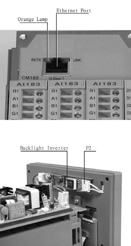


86 FDC-VR18_Manual_V2.37_November-2011.doc 86
87 FDC-VR18_Manual_V2.37_November-2011.doc 87
88 8. FAQs frequently asked questions Q1: What is the maximum scale low and scale high values we can set in the recorder for the analog inputs and outputs? A1: The minimum low scales of analog input are various , , , , , depending on the position of the decimal point The maximum high scales of analog input are various 45536, , , , , and depending on the position of the decimal point The minimum low scales of Math input are various , , , , , depending on the position of the decimal point The maximum high scales of Math input are various 32767, , , , , and depending on the position of the decimal point Q2: What is the maximum distance between PC and Recorder for Ethernet communication? A2: The distance is limited in 100 meters. If it is farer than that, then you can use Hub or networking bridge to strengthen the signal. Q3: What is the maximum distance if PC is accessing data from recorder on wireless network through Ethernet protocol? A3: Maximum distance should be within 30 meters. Also make sure that there are no obstacles/ HT cables between PC and recorder to avoid communication errors. Also Noise could effect the wireless communication at the factory floor. Q4: Is there any battery available inside the recorder, which needs to be changed frequently? A4: The lithium battery Toshiba CR V/220mAH can last for many years. It can be replaced by local sourcing if Real Time Clock is not working properly. Q5: What is the accuracy of Real Time Clock in the recorder? A5: The crystal oscillator used in recorder could have a lag time in a few seconds each week. Press Synchronization button in PC software Observer II to synchronize the time between PC and the recorder. The temperature inside the housing has an effect on accuracy of Real Time Clock of crystal oscillator. Temperature range Time lag per month 10 ~ 40 C 18 seconds 0 or 50 C 52 seconds -10 or 60 C 107 seconds FDC-VR18_Manual_V2.37_November-2011.doc 88
89 Q6: What kind of security is available in recorder? A6: There are two kinds of security. 1. Normal security offers a common password. 2. High security with CFR-21 Part 11 type features is available from version 2.2 and later versions on both recorder and PC software Observer. It supports maximum 30 users with different passwords. The Supervisor has the right to define other supervisors and operators. The supervisor can change configuration, save and clear data but not operators. Operators can only view the historical data, events and status. Q7: What is Boot Rom? Anything related to Math option? Is it possible to upgrade it into new version via internet or CF card? A7: Boot ROM is a chip installed in the recorder containing system boot information. The Boot ROM BT182 is supplied with Math, Counter, Totalizer & CFR-21 part 11 type features. It is not possible to upgrade the Boot ROM via Internet or CF card. Q8: How are the VR18 recorder firmware & PC Observer software upgraded to latest version? A8: If necessary, contact your supplier about the latest updates or visit our website Your supplier is able to supply the latest version of recorder firmware system and PC software on CD or via or FTP (file transfer protocol). Follow the procedure to update the recorder firmware. Install the new version of Observer software; it will automatically uninstall the old one. Q9: Are there other considerations prior to updating recorder firmware to most recent version? A9: Any recorder firmware before V1.20 must first be updated to V1.20. Direct update to the latest version could damage the DOC. Once recorder has V1.20 it may be updated to the most current firmware. Note V1.20 began shipping approx. January Q10: What are the differences between Observer I & Observer II PC software? A10: Observer I is supplied as standard & Observer II is supplied at additional cost. Observer I is used for recorder configuration from PC and reading historical data in PC at set time period of 1 to 24 hours. Data is exchanged between recorder & PC via CF card. Observer II is used for real time data monitoring in PC via Ethernet or RS232/422/485 along with configuration and historical data view. Q11: How many AI, AO, DI, DO cards, and 24VDC auxiliary power card can be inserted into the recorder? A11: Maximum 6 cards in any combination can be inserted into rear Slots. Q12: What are those larger capacities of compact flash cards supported by the recorder and FDC-VR18_Manual_V2.37_November-2011.doc 89
90 recommended manufacturer? A12: If the user prefers to use larger capacities CF card we usually recommend 2GB. To be fully compatible, we only recommend one brand SanDisk CF card. Q13: What is the product warranty period of time? How does the user handle the defective recorder? A13: Warranty period is 24 months from ship date. Contact your supplier or Future Design Controls directly. Q14: What is the procedure to transfer data from the internal memory to CF card after the internal memory is full? A14: After 8MB internal memory is full, the earliest data and events will be saved into CF card in small batch automatically, details in 3.11 Small icons. Q15: Is Alarm banner available in the recorder along with customized message display? A15: Alarm banner is unavailable for customized message display. The alarm banner appears after alarms or events occurred, or the internal memory or CF card is running shortage. A buzzer can be set to activate if any alarms/events arise. Q16: How many analog and math channels available and is it possible to retransmit these channels? A16: Maximum18 analog inputs plus 18 math inputs are available in one recorder. It is possible to retransmit the analog and math channels by using 3-channel current output card AO183I or 3- channel voltage output card AO183V. Q17 Is the recorder supplied with OPC server? A17: The OPC server is not available in the VR18. However Observer II PC software does offer DDE solution to allow data transferred to other devices like PLC, SCADA etc. Please review a few examples in 5.5 DDE dynamic data exchange. Q18: Which protocols and hardware interface recorder supports? A18: The protocol for RS-232, RS-422, RS-485 communication is Modbus RTU. For Ethernet communication, the protocol is TCP/IP. Q19: How many recorders can be connected in a network? A19: It depends on hardware interface selected. With Ethernet communication a maximum, 255 devices can be connected in the network with each device requiring a unique IP address. With RS 485 communication a maximum of 247 units can be connected in the network. FDC-VR18_Manual_V2.37_November-2011.doc 90
91 Q20: How many recorders can be viewed in the Real-time Viewer of PC software Observer II? A20: Maximum 1024 tags can be viewed from the Real-time Viewer. These tags cover AI, Math, DI, DO, Counter and Totalizer, excluding AO. As an example if on average each recorder has 6 tags read, then the Real-time Viewer can view maximum of 170 recorders. Q21: Once the user forgot the password, is there a common password? If not, how to reset recorder to the factory settings? A21: There is no common back door or hidden password. If the password is lost the recorder must be reset to factory default settings using the RESET procedure. Press and hold the top left key with power off and turn on the power. Do not release it until you hear two "BI " sounds. Turn the power off and on again. All factory settings will be restored. Please note that after this procedure all project configuration data have been erased; the recorder will have to be re-configured. Q22: To change the analog input using Observer I or II software, what is the next step after changing the dip switches and jumpers on the analog input card? A22: Observer II connected to recorder via Ethernet or RS232/422/485; press the icon to receive configuration from the recorder to PC. Observer I or II via CF card; first save new configuration on recorder since changing DIP-switch settings on input card to CF card. Then open configuration file from within Observer. Modify the configuration as necessary and send the new configuration back to the recorder in the same fashion as it was read. Q23: Which type of Ethernet cable should be used to connect with the recorder? A23: Straight through cable should be used for the real network connection between HUB and recorder. Cross-through [patch cable] cable should be used for the non-real network connection such as between PC and recorder. Q24: How many days the data can be stored in CF card? A24: It depends on the number of channels, the log speed of channels, and the memory size of CF card. If the recorder is used with 6-channel inputs, an easy chart to show the maximum days CF can store the data. CF card memory size: 1GB Log speed 1 second 980 days 10 seconds 9,870 days 120 seconds 118,510 days FDC-VR18_Manual_V2.37_November-2011.doc 91

92 Q25: Is it possible to display all the selected channels in one page on recorder? A25: Yes, press Page key to get to Page all mode. Then, all selected channels in digits can be displayed in one page. Q26: Is it possible to print out the data in selected time from the recorder? A26: No, it is not possible to connect printer directly to the recorder. However it is possible to print out the data in selected times from the Observer software. Observer also supports exporting Historical & Event files in.csv format which when opened in Excel can be sorted and printed. If any error appears when user attempts to print data, i.e. floating point error, the reason might be that data is not available for selected pens. Search by a specific time or by a period of time making sure that data is shown on the trend line. Select the pen correctly and proceed with the printing. Q27: How many timers, counters and totalizers are available in a recorder? A27: 6 counters, 6 timers and 18 totalizers are available in one recorder. Q28: Can I use digital inputs for the counting application? A28: The sample rate of recorder is 200 msec and the quickest data log speed is 1 sec per data. It is possible to use digital input(s) as counter(s) if the duration between two pulses is more than 200 msec. Recorder will not detect pulses if the duration is less than 200 msec. Recorder can detect maximum 5 counts/sec or 300 counts/min or counts/hr. For applications pulse duration faster than 200 msec a third party converter is required (pulse to 4-20mA converter). Q29: When Observer II software, the user may see the following message, what is the next move? A29: Most likely the Observer software file was corrupted in the PC; possible reasons might be a virus or installation of new incompatible software with your operating system. The solution is to uninstall the old Observer software as per procedure given in section 1.4 of this software guide. Then, install the new Observer software from CD supplied. If the problem still can t be solved, then uninstall the old Observer software and create a back up for the historical and real-time folders under C:/Observer and remove Observer folder from C: Then install the new Observer software again. FDC-VR18_Manual_V2.37_November-2011.doc 92
LBVR1718. Description. Features channel paperless recorder
 LBVR1718 18 - channel paperless recorder Description It is the world first paperless recorder of the same size in highest resolution 640x480 pixels VGA TFT display, infrared detector, maximum 18 channels,
User Manual. Paperless Recorder VR06
 User Manual Paperless Recorder VR06 1st Edition, 02/2007 Contents Page Safety --------------------------------------------------------------------------------- 4 Safety Symbols --------------------------------------------------------------------------
User Manual. Paperless Recorder VR18
 User Manual Paperless Recorder VR18 UMVR181T Brainchild Electronic Co., Ltd. 19th Edition, 05/2018 Contents Page Safety ---------------------------------------------------------------------------------
RD2000, 5.6" display. All models shown smaller than actual size.
 Paperless Recorders RD1000/RD2000/RD3000 Series RD1000, 4.3" display RD2000, 5.6" display RD3000, 12.1" display All models shown smaller than actual size. Color TFT Touch Screen Display: 4.3", 5.6" and
USER MANUAL MULTI COLOR TOUCH SCREEN PAPERLESS RECORDER MODEL : ARC2020
 USER MANUAL MULTI COLOR MODEL : ARC2020 ACCSYS ELECTRONICS 140/6B, GOLDEN INDUSTRIAL ESTATE, JAWAHARLAL NEHRU ROAD, GERUGAMBAKKAM, CHENNAI - 600122 Tel: 044 60505599 / 60505511 E-mail : sales@accsyselectronics.com
Tempco Instruction Manual
 Tempco Instruction Manual 1/16 DIN Solid State Temperature Controller Relay Output Solid State Output For Heating Model Numbers: TEC-901, TEC-902, TEC-905 Temperature controls in this series are designed
PanelView Plus/VersaView CE Terminals and Display Modules
 Installation Instructions PanelView Plus/VersaView CE Terminals and Display Modules (Catalog Numbers 2711P-xxxxxx, 6182H-xxxxxx) English Inside: Overview...2 For More Information...2 Modular Components...3
USER MANUAL MULTI COLOR TOUCH SCREEN PAPERLESS RECORDER TPLR-96 Series
 USER MANUAL MULTI COLOR TOUCH SCREEN PAPERLESS RECORDER TPLR-96 Series TEMPSEN DEVICES Plot No : 2&3, Balaji Nagar, 4 th Street, Mettukuppam, Thoraipakkam, Chennai-600097 Tele fax : +91-44-24581758,Mobil
1/32-DIN TEMPERATURE CONTROLLER INSTALLATION, WIRING AND OPERATION MANUAL FORM 3882
 1/32-DIN TEMPERATURE CONTROLLER INSTALLATION, WIRING AND OPERATION MANUAL FORM 3882 This manual is intended for use in support of installation, commissioning and configuration of the 1/32-DIN Temperature
PR series User Manual
 PR series User Manual UMPR01B 2nd Edition, 06/2015 TABLE OF CONTENTS 1. GENERAL DESCRIPTION... 8 1.1 UNIQUE FEATURES OF RECORDER... 8 1.2 COMPARISON OF PR SERIES RECORDERS... 12 1.3 EXPANDABLE INPUT AND
VR18 FAQs - Frequently Asked Questions
 VR18 FAQs - Frequently Asked Questions Q1: What is the maximum scale low and scale high values we can set in the recorder for the analog inputs and outputs? Q2: What is the maximum distance between PC
PR Series Paperless Recorders
 PR Series Paperless Recorders Head Office: Brainchild Electronic Co., Ltd. 209 Chongyang Road, Nangang Dist., Taipei 11573, Taiwan Tel: +886-2-2786-1299 Fax: +886-2-2786-1395 Website: www.brainchild.com.tw
UDC 1000 and UDC 1500 MICRO-PRO SERIES UNIVERSAL DIGITAL CONTROLLERS
 UDC 1000 and UDC 1500 MICRO-PRO SERIES UNIVERSAL DIGITAL CONTROLLERS EN0I-6041 12/99 PRODUCT SPECIFICATION SHEET OVERVIEW The UDC 1000 and UDC 1500 are microprocessor-based 1/16 DIN and 1/8 DIN controllers
User s Guide RD1000, RD2000, RD3000 SERIES. Paperless Recorders. Shop online at omega.com SM
 User s Guide Shop online at omega.com SM e-mail: info@omega.com For latest product manuals: www.omegamanual.info RD1000, RD2000, RD3000 SERIES Paperless Recorders www.omega.com info@omega.com Servicing
895/896M Frequency Output Math Modules
 895/896M Frequency Output Math Modules Application Example Both models are designed for integrator/totalizer applications. The 896M is ideal for demand metering applications. With one high speed pulse
WARNING: Do not use the thermometer/data logger before you read the users manual and the following instructions.
 55 This unit passes the following tests EN 61326-1:2006 (CISPR11,IEC/EN 61000-3-2:2006, IEC/EN 61000-3-3: 1995+A1 :2001+A2:2005 IEC/EN 61000-4-2/-3/-5/-6/-11) WARNING: Do not use the thermometer/data logger
LAUREL ELECTRONICS, INC.
 LAUREL ELECTRONICS, INC. Laureate RTD Temperature Panel Meter / Controller Features Factory calibrated for 100Ω platinum, 10Ω copper & 120Ω nickel RTDs 2, 3 or 4-wire connection with lead resistance compensation
Voltage Transducer UMT516 / MT516
 Voltage Transducer UMT516 / MT516 True RMS AC voltage measurements Voltage auto range measurements up to 600V # Wide frequency measurement range 16 400 Hz High accuracy class 0.2 (IEC-688), 0.1 on communication
DATAWATCH IX MONITOR/RECORDER OVERVIEW FEATURES AND BENEFITS. Datasheet
 OVERVIEW The DATAWATCH IX monitor offers an excellent graphical display and recording device for a box of its size. The compact panel mount unit offers four isolated or eight non-isolated high accuracy
The PM1000 series is a universal 4 digit LED plug-on display for transmitters with 4-20mA 2 wire output and fitted with DIN43650 connector.
 PM1000 SERIES PLUG-ON DISPLAY BRIGHT LED DISPLAY INDICATION RANGE -999 TO +9999 FITS TO DIN 43650 CONNECTOR PLUG-ON TO ANY TRANSMITTER WITH 4-20MA OUTPUT EASY TO SCALE ON SITE ROBUST DESIGN SET POINT OPTION
Operating Manual. Dynisco /8 DIN Indicator Concise Product Manual
 Dynisco 1490 1/8 DIN Indicator Concise Product Manual 59476-9 Operating Manual -1- CAUTION: Installation should be only performed by technically competent personnel. Local Regulations regarding electrical
Digital Indicator Solutions
 Digital Indicator Solutions Loop-Powered Attachable Compact Attachable Loop-Powered Smart Compact System Loop-Powered Compact Smart System Intelligent Smart System "Intelligent" Options Dual & Display
LAUREL. Laureate RTD Temperature Panel Meter / Controller ELECTRONICS, INC. Features. Description. Specifications
 LAUREL ELECTRONICS, INC. Laureate RTD Temperature Panel Meter / Controller Features Factory calibrated for 100Ω platinum, 10Ω copper & 120Ω nickel RTDs 2, 3 or 4-wire connection with lead resistance compensation
IO-PT4. Component identification. User safety and equipment protection guidelines. Unitronics Industrial Automation Systems 1
 IO-PT4 I/O Expansion Module 4 PT100 Inputs (-50 to 460 C) The IO-PT4 is an I/O expansion module that can be used in conjunction with specific Unitronics OPLC controllers. The module offers 4 PT100 inputs
PR series Quick User Manual
 PR series Quick User Manual UMQPR01B 2nd Edition, 11/2016 TABLE OF CONTENTS 1. GENERAL DESCRIPTION... 5 1.1 UNIQUE FEATURES OF RECORDER... 5 1.2 COMPARISON OF PR SERIES RECORDERS... 5 1.3 SMART MECHANISM...
Mini Digital Multimeter
 User's Guide Mini Digital Multimeter Model MN15 99 Washington Street Melrose, MA 02176 Phone 781-665-1400 Toll Free 1-800-517-8431 Visit us at www.testequipmentdepot.com Back to the Extech MN15/MN16 Series
Extruder Controls ExtruVision S
 Extruder Controls ExtruVision S ExtruVision S - The compact system solution for controlling, visualization, and operating extrusion systems Combination of control panel BA Touch with 5.7'' monitor and
Future Design Controls, Inc. VR Series (VR06 & VR18) Firmware Release Notes; v0.94 to v2.37
 Firmware Release Notes; v0.94 to v2.37") V2.38 (10-30-2013) [applies to both VR06 & VR18] 1. Bug fixed: Filter bounce for alarm function V2.37 (07-2010) [applies to both VR06 & VR18] 1. Compatible with Future Design Controls DAQ software (IO
V2.38 (10-30-2013) [applies to both VR06 & VR18] 1. Bug fixed: Filter bounce for alarm function V2.37 (07-2010) [applies to both VR06 & VR18] 1. Compatible with Future Design Controls DAQ software (IO
Analog Voltage Combination Module
 Analog Voltage Combination Module T1F-8AD4DA-2 8-channel analog voltage input 4-channel analog voltage output The combination 8-in and 4-out voltage module uses a T1K-8B or T1K-8B-1 base, which is purchased
CDD Carbon Dioxide Transmitter
 Introduction The OSA CO2 transmitter uses Infrared Technology to monitor CO2 levels within a range of 0 2000 ppm and outputs a linear 4-20 ma or 0-5/0-10 Vdc signal. The enclosure is designed to operate
Rhino Buffer Module PSM24-BFM600S. Operating Instructions
 Rhino Buffer Module PSM24-BFM600S Operating Instructions RHINO BUFFER MODULE PSM24-BFM600S Description The PSM24-BFM600S Buffer Module will hold the output voltage of a 24 VDC power supply after brownouts
DPR 100 A/B Analog Scales
 DPR 100 A/B Analog Scales 0I-6030 8/95 Pen and Multipoint 100 mm Digital Recorders Specification and Technical Data Introduction The DPR 100 is a microprocessor based 100 mm (4 inch) strip chart recorder
12-36 VDC/12-24 VAC Power Option 4-Digit Display, 0.56 (14.2 mm) or 1.20 (30.5 mm)
 or 1.20 (30.5 mm)") 4-20 ma & Relay Output Features 4-20 ma, ± 10 V, TC & RTD Inputs 12-36 VDC/12-24 VAC Power Option 4-Digit Display, 0.56 (14.2 mm) or 1.20 (30.5 mm) 24 VDC @ 200 ma Transmitter Power Supply Options Type
4-20 ma & Relay Output Features 4-20 ma, ± 10 V, TC & RTD Inputs 12-36 VDC/12-24 VAC Power Option 4-Digit Display, 0.56 (14.2 mm) or 1.20 (30.5 mm) 24 VDC @ 200 ma Transmitter Power Supply Options Type
Instrumentation PPS Series Videographic Data Recorders. PPS Series Videographic Data Recorders. Now with Touch Screen Technology!
 Now with Touch Screen Technology! PPS-1000 PPS-2000 PPS-3000 Product Overview The PPS Series is a major advance in the market for Paperless Videographic Data Recorders incorporating Touch Screen Technology
TRACKER 220 SERIES. Digital Panel Indicators. A Complete Range of Universal Input Digital Panel Indicators for Temperature and Process Measurement
 TRACKER 220 SERIES Digital Panel Indicators A Complete Range of Universal Input Digital Panel Indicators for Temperature and Process Measurement TRACKER 220 SERIES INDICATORS Universal Input Analogue Output
Mini Digital Multimeter
 User Manual Mini Digital Multimeter Model MN15A Additional User Manual Translations available at www.extech.com Introduction Congratulations on your purchase of the Extech MN15A MultiMeter. The MN15A offers
The Tracker 220 Series A Complete Range of Universal Input Digital Panel Indicators for Temperature and Process Measurement
 Acquisition Measurement Control The Tracker 220 Series A Complete Range of Universal Input Digital Panel Indicators for Temperature and Process Measurement TRACKER 220 SERIES INDICATORS Universal Input
DIGITAL INDICATING CONTROLLER
 DB1000 SERIES DIGITAL INDICATING CONTROLLER The DB1000 series is a 96 96mm digital indicating controller with the indicating accuracy of ±0.1% and the control cycle of approximately 0.1 seconds. Various
QUICK SETUP GUIDE PMC-1000, PMC-1001, PMM-1000, PMB PM Series Power Meter. Safety Information. Equipment Maintenance and Service.
 PM Series Power Meter QUICK SETUP GUIDE PMC-1000, PMC-1001, PMM-1000, PMB-1960 Safety Information DANGER! HAZARD OF ELECTRIC SHOCK, EXPLOSION, OR ARC FLASH Follow safe electrical work practices. See NFPA
Trident and Trident X2 Digital Process and Temperature Panel Meter
 Sign In New User ISO 9001:2008 Certified Quality System Home Products Online Tools Videos Downloads About Us Store Contact Policies Trident and Trident X2 Digital Process and Temperature Panel Meter Products
Dual channel temperature logger with two voltage inputs 0-5V Instruction Manual
 LOGGER S0541 Dual channel temperature logger with two voltage inputs 0-5V Instruction Manual Instruction Manual for use of S0541 logger Instrument is designed for measurement and record of temperature
User's Guide. Digital Multimeter. Model MN42
 User's Guide Digital Multimeter Model MN42 Introduction Congratulations on your purchase of the Extech MN42 MultiMeter. The MN42 offers AC/DC Voltage, DC Current, and Resistance testing. Proper use and
Multi-instrument Communication, MIC-2 MKII DIN Quick Start Guide
 Multi-instrument Communication, MIC-2 MKII DIN Quick Start Guide Warnings and legal information Installation and terminals Communication I/O options Alarming Utility software More information Specifications
S-14 S-14. Compact Digital Multimeter. Compact Digital Multimeter
 S-14 Compact Digital Multimeter S-14 Compact Digital Multimeter SAFETY INFORMATION The following safety information must be observed to insure maximum personal safety during the operation at this meter
HCS-3600 / 3602 / 3604 Laboratory Grade & High RFI Immunity Switching Mode Power Supply with Rotary Encoder Control
 HCS-3600 / 3602 / 3604 Laboratory Grade & High RFI Immunity Switching Mode Power Supply with Rotary Encoder Control 1. INTRODUCTION User Manual This family of efficient, upgraded SMPS with small form factor,
/8 DIN Universal Process Indicator
 Data Sheet SS/_ High visibility LED display the clearest view of your process status.% measurement accuracy precise indication of process measurement Analog and relay outputs as standard alarm and retransmission
LLR-MOD Modbus Light Level and Occupancy Sensor
 Product sheet SN1.418 Type LLR-MOD LLR-MOD Modbus Light Level and Occupancy Sensor The LLR-MOD sensors are designed to measure Light Level (LUX) in the room spaces and have built-in RS485 Modbus communication
R1M-GH THERMOCOUPLE & DC INPUT MODULE MODEL. Remote I/O R1M Series. (16 points)
") Remote I/O R1M Series THERMOCOUPLE & DC INPUT MODULE (16 points) MODEL MODEL & SUFFIX CODE SELECTION R1MGH2T MODEL Modbus protocol I/O TYPE GH2 : Thermocouple or DC input, 16 points FIELD TERMINAL TYPE
Remote I/O R1M Series THERMOCOUPLE & DC INPUT MODULE (16 points) MODEL MODEL & SUFFIX CODE SELECTION R1MGH2T MODEL Modbus protocol I/O TYPE GH2 : Thermocouple or DC input, 16 points FIELD TERMINAL TYPE
CDD4 Duct Carbon Dioxide Transmitter
 Drill or punch a 1-1/8 or 1-1/4 hole in the duct at the preferred location and insert the probe into the hole to mark the enclosure mounting holes. Remove the unit and drill the four mounting holes. Clean
MYRIAD QLC 4-CHANNEL MONITOR/CONTROLLER INSTRUCTION MANUAL
 MYRIAD QLC 4-CHANNEL MONITOR/CONTROLLER INSTRUCTION MANUAL VISIT OUR WEBSITE SIGMACONTROLS.COM MYR QLC MANUAL 013114 2 TABLE OF CONTENTS INTRODUCTION 3 Ordering Information Specifications Features WIRING
TRACKER 240 SERIES. Load Cell and Weighing Indicators. A Precision Measurement Instrument with Outstanding Features
 TRACKER 240 SERIES Load Cell and Weighing Indicators A Precision Measurement Instrument with Outstanding Features TRACKER 240 SERIES INDICATORS Ratiometric Measurement Tare and Auto Transducer Excitation
LAUREL ELECTRONICS, INC.
 Description LAUREL ELECTRONICS, INC. Laureate Pulse or Analog Input Batch Controller Automatic batch control for repetitive liquid fill operations Features Available for turbine flow meter pulse signals
DPST-NO None 2 channels Auto-reset Inverse (+/-) 24 VAC/VDC 4 G9SB-2002-A 1 channel or 2
 24 VAC/VDC 4 G9SB-2002-A 1 channel or 2") Safety Relay Unit Ultra Slim Safety Relay Unit 17.5 mm wide models available with 2 or 3 poles. 22.5 mm wide 3 pole models also available EN Standards (TÜV approval) DIN-track mounting possible Ordering
Safety Relay Unit Ultra Slim Safety Relay Unit 17.5 mm wide models available with 2 or 3 poles. 22.5 mm wide 3 pole models also available EN Standards (TÜV approval) DIN-track mounting possible Ordering
Owner's Manual. True RMS Multimeter. Model No Safety Operation Maintenance Español
 Owner's Manual True RMS Multimeter Model No. 82023 CAUTION: Read, understand and follow Safety Rules and Operating Instructions in this manual before using this product. Safety Operation Maintenance Español
Y800 Plus Frequency, Rate & Period Meter With dual, independently field-scalable channels
 Y800 Plus Frequency, Rate & Period Meter With dual, independently field-scalable channels Description Features Frequencies from 0.005 Hz to 1 MHz 6-digit resolution at update rates up to 25/s Selectable
PMC 530 Series Advanced Multifunction Meter
 IEC 62053 22 Class 0.5S WF Capture @ 128 samples/cycle WF and Data Recording Harmonics & Transient Monitoring I residual Monitoring Setpoint Alarms, SOE Log RS 485 and I/O Capabilities Large, Bright, Backlit
User Manual. 400Amp AC Clamp Meter + NCV. Model MA430. Additional User Manual Translations available at
 User Manual 400Amp AC Clamp Meter + NCV Model MA430 Additional User Manual Translations available at www.extech.com Introduction Congratulations on your purchase of this Extech MA430 Clamp Meter. This
Multifunction Transducer MT440
 Multifunction Transducer MT440 Voltage and current auto range measurements up to 600V, 12.5A Universal wide auxiliary power supply range 24 300 Vdc, 40 276 Vac Power accuracy class 0.5 (EN 60 688), Up
INSTALLATION DKM-409 NETWORK ANALYSER WITH HARMONIC MEASUREMENT AND SCOPEMETER. Before installation:
 DKM-409 NETWORK ANALYSER WITH HARMONIC MEASUREMENT AND SCOPEMETER The DKM-409 is a precision instrument designed for displaying various AC parameters in 3-phase distribution panels. Thanks to its isolated
Strip Chart Recorders Specification Sheet
 4101C, 4101M 4102C, 4102M MODELS Continuous Pen Recording 1, 2, 3 or 4 Pens Multi-point Recording Providing 6 Colour traces High Visibility Display 4101C, 4101M Clear Analogue Scale 4102C, 4102M Large
MIC-2 MKII, Multi-instrument DATA SHEET
 MIC-2 MKII, Multi-instrument DATA SHEET Measurements All 3-phase AC measurements True RMS 4-Quadrant energy Power Quality Analysis Replaces analogue meters RS-485 Modbus RTU protocol TCP/IP Modbus (optional)
DMT345 and DMT346 Dewpoint Transmitters
 DMT345 and DMT346 Dewpoint Transmitters for High Temperature Applications Features DMT345 measures humidity at temperatures up to 180 C (356 F) DMT346 measures humidity at temperatures up to 350 C (+662
- SELF-TUNING PID ALGORITHM - INTUITIVE COLOR DISPLAY WITH TEXT MESSAGING - UNIVERSAL PROCESS AND TC/RTD INPUTS - MULTI- FUNCTION RAMP- DWELL/PROCESS
 ELK. ETK COMPACT BASIC CONTROL - SELF-TUNING PID ALGORITHM - INTUITIVE COLOR DISPLAY WITH TEXT MESSAGING - UNIVERSAL PROCESS AND TC/RTD INPUTS - MULTI- FUNCTION RAMP- DWELL/PROCESS TIMER - SOFT START OUTPUT
Dual channel temperature logger with two binary inputs and LCD display Instruction Manual
 LOGGER S0841 Dual channel temperature logger with two binary inputs and LCD display Instruction Manual Instruction Manual for use of S0841 logger Instrument is designed for measurement and record of temperature
Digital ac/dc (24V) Input Module
 Input Module") Installation Instructions Digital ac/dc (24V) Input Module Catalog Number 1771-IND, Series C Topic Page Important User Information 2 Before You Begin 3 Power Requirements 3 Prevent Electrostatic Discharge
Installation Instructions Digital ac/dc (24V) Input Module Catalog Number 1771-IND, Series C Topic Page Important User Information 2 Before You Begin 3 Power Requirements 3 Prevent Electrostatic Discharge
Instrumentation PPS Series Videographic Data Recorders. PPS Series Videographic Data Recorders. Now with Touch Screen Technology!
 Now with Touch Screen Technology! PPS-1000 PPS-2000 PPS-3000 Product Overview The PPS Series is a major advance in the market for Paperless Videographic Data Recorders incorporating Touch Screen Technology
General Specifications. P2-08THM Analog Input
 General Specifications Operating Temperature Storage Temperature Humidity Environmental Air Vibration Shock Field to Logic Side Isolation Heat Dissipation Enclosure Type Agency Approvals Module Keying
MAKING MODERN LIVING POSSIBLE AK-255 CO 2. Controller On-Site Installation Guide DANFOSS ELECTRONIC CONTROLS & SENSORS
 MAKING MODERN LIVING POSSIBLE Controller On-Site Installation Guide DANFOSS ELECTRONIC CONTROLS & SENSORS How to Use This Guide Read this Guide completely as you install and start up your new Controller.
INSTRUCTION SHEET. Eaton Logic Controller ELCB Controllers
 2010-12-10 5011699201-PBB1 Eaton Logic Controller ELCB Controllers INSTRUCTION SHEET [Applicable Controllers] ELCB-PB10 ELCB-PB14 ELCB-PB20 ELCB-PB30 ELCB-PB40 IL05001005E 002-1310020-02 Thank you for
PM Series Power Meter
 PM Series Power Meter Quick Setup Guide - PMC-1000, PMC- 1001, PMM-1000, PMB-1960 Safety Information DANGER! HAZARD OF ELECTRIC SHOCK, EXPLOSION, OR ARC FLASH Follow safe electrical work practices. See
LC0 DVP
 2010-09-24 5012602300-2LC0.... DVP-1071070-01 POWER RUN ERROR L.V NET ZER O MAX MOTION NET ZER O MAX MOTION CH1 CH2 SHD SHD ENGLISH Thank you for choosing Delta s DVP series PLC. Delta releases DVP02LC-SL
HITACHI. EH-150 series PLC EH-RTD8 Resistance Temperature Detective input module Instruction manual. Safety precautions
 HITACHI EH-150 series PLC Resistance Temperature Detective input module Instruction manual Thank you for purchasing a Hitachi Programmable Logic Controller. To operate it safely, please read this instruction
5450 NW 33rd Ave, Suite 104 Fort Lauderdale, FL Fruitland Ave Los Angeles, CA UM Channel Monitor.
 5450 NW 33rd Ave, Suite 104 Fort Lauderdale, FL 33309 3211 Fruitland Ave Los Angeles, CA 90058 UM-600 6-Channel Monitor Version 2 Installation and Operation Manual Rev. G P/N145F-12990 PCO 00007462 (c)
1.6. Counters, Panel Meters, Tachometers and Timers. Contents Description Fusion Integrated Machine Control Standards and Certifications...
 .6 Contents Standards and Certifications............... Product Selection....................... Technical Data and Specifications........... Dimensions............................ Learn Online Page V3-T-04
Multi-instrument Communication, MIC-2 MKII DIN Quick Start Guide
 Multi-instrument Communication, MIC-2 MKII DIN Quick Start Guide Warnings and legal information Installation and terminals Communication I/O options Alarming Utility software More information Specifications
ASI Systems ML5740A Series
 ML5740A Series Electric Linear Valve Actuators Non-Spring Return APPLICATION The ML5740A series actuators operate standard ASI Systems valves in heating, ventilating and air conditioning (HVAC) applications.
User Guide True RMS Multimeter Extech EX205T
 User Guide Extech EX205T True RMS Digital Multimeter Extech EX210T True RMS Digital Multimeter IR True RMS Multimeter Extech EX205T Introduction Thank you for selecting the Extech EX205T True RMS Auto-ranging
MIC-2 MKII & MIC-2 MKII DIN, Multi-instrument DATA SHEET
 & DIN, Multi-instrument DATA SHEET Measurements All 3-phase AC measurements True RMS 4-Quadrant energy Power Quality Analysis Replaces analogue meters RS-485 Modbus RTU protocol TCP/IP Modbus (optional)
Line A. Inverse parallel scrs. Load a FUSION. Line B SCR POWER. O delta CONTROLLERS. Line c. inverse parallel scrs. Load C. FUSION Brochure Rev 3.
 Line A Inverse parallel scrs Load a Line B FUSION SCR POWER O delta CONTROLLERS Line c inverse parallel scrs Load C FEATURES Auto-Ranging Input Voltage 24-600 VAC, 45-65 Hz AC or DC Output AC Models: 50-1200
SX 6000 Paperless Recorder
 SILVER AUTOMATION INSTRUMENTS HTTP://WWW.SILVERINSTRUMENTS.COM RUNYI GROUP SX 6000 Paperless Recorder Product Overview SX6000 Paperless Recorder color-screen paperless recorder has 16-channel universal
RS Stock No Instruction Manual RS Input Data Logging Thermometer
 RS Stock No. 730-0458 Instruction Manual RS-1384 4 Input Data Logging Thermometer EN FR IT DE ES TABLE OF CONTENTS / EN TITLE TABLE OF CONTENTS PAGE 1. INTRODUCTION FEATURE... 1 2. SPECIFICATIONS... 2
Model A Mini AC/DC Clamp Meter. User's Guide
 Model 380950 80A Mini AC/DC Clamp Meter User's Guide Introduction Congratulations on your purchase of the Extech 80A Mini AC/DC Clamp Meter. The Model 380950 measures AC/DC Current, AC/DC Voltage, Resistance,
QUICK SETUP GUIDE. BCM2 Series Branch Circuit Monitors. Safety Information. Equipment Maintenance and Service. Raritan DANGER!
 QUICK SETUP GUIDE BCM2 Series Branch Circuit Monitors Safety Information DANGER! HAZARD OF ELECTRIC SHOCK, EXPLOSION, OR ARC FLASH Follow safe electrical work practices. See NFPA 70E in the USA, or applicable
ACT-1B Series Panel Tachometer
 MONARCH INSTRUMENT Instruction Manual ACT-1B Series Panel Tachometer Printed in the U.S.A. Copyright 2009 Monarch Instrument, all rights reserved 1071-4843-111R 0909 15 Columbia Drive Amherst, NH 03031
Comprehensive Modular Genset Controller
 Inteligen Learn More Comprehensive Modular Genset Controller Brief Description The Inteligen is a comprehensive controller for single and multiple generating sets operating in standby or parallel to the
Part No. Z , IA Jul OPERATION MANUAL. High Voltage Digitalmeter A
 Part No. Z1-109-820, IA001705 Jul. 2016 OPERATION MANUAL High Voltage Digitalmeter 149-10A Use of Operation Manual Please read through and understand this Operation Manual before operating the product.
Programmable Relay ZEN V2 Units
 Programmable Relay ZEN V2 Units Please read and understand this catalog before purchasing the products. Please consult your OMRON representative if you have any questions or comments. Refer to Warranty
DTS 310. DIN Rail Mounted, Indoor Rated Revenue Grade Electrical Sub-meter. Page 1. Measurlogic MQ A
 DTS 310 DIN Rail Mounted, Indoor Rated Revenue Grade Electrical Sub-meter Page 1 1 PRODUCT OVERVIEW... 3 1.1 SUPPLIED ITEMS... 3 1.2 DOCUMENT CONVENTIONS... 4 1.3 PRODUCT SPECIFICATION... 4 1.3.1 Current
Setting method Indication Control Output Model method mode Thermocouple (with sensor burnout detection circuit)
") Temperature Controller DIN-sized (48 x 48 mm) Temperature Controller With Digital Setting Compact, low-cost Temperature Controller Incorporates proportional adjustment and reset adjustment function. Incorporates
Temperature Controller DIN-sized (48 x 48 mm) Temperature Controller With Digital Setting Compact, low-cost Temperature Controller Incorporates proportional adjustment and reset adjustment function. Incorporates
Product Description. Contents. Fusion Series. New Information December 2003
 Fusion Series Technical Data New Information December 2003 Durant Fusion Product Description The Durant Fusion from Eaton Electrical is an industrial control unit consisting of a high speed count control
LAUREL. Laureate Digital Panel Meter for Process and Ratiometric Signals ELECTRONICS, INC. Features. Description
 LAUREL ELECTRONICS, INC. Laureate Digital Panel Meter for Process and Ratiometric Signals Features Reads process signals from ±200 mv to ±600V or ±2 ma to ±5A full scale Ratiometric mode for bridges and
IO-DI8-TO8 I/O Expansion Module 8 Inputs, 8 Outputs
 IO-DI8-TO8 I/O Expansion Module 8 Inputs, 8 Outputs The IO-DI8-TO8 is an I/O expansion module that can be used in conjunction with specific Unitronics OPLC controllers. The module offers 8 digital inputs,
Universal AC Power Source + AC Power Analyzer
 User's Guide Universal AC Power Source + AC Power Analyzer Model 380820 Introduction Congratulations on your purchase of the Extech Model 380820. This Universal AC Power Source and AC Power Analyzer can
FLEX Ex Spring Clamp Terminal Base
 Installation Instructions FLEX Ex Spring Clamp Terminal Base (Cat. No. 1797-TB3S) 1 10 11 4 Only remove this cover plug if connecting another terminal base unit. 3 5 6 12 2 7 8 9 41253 Component Identification
SX90 Process Controller
 Local regulations may restrict the use of this product to below the conditions quoted. In the interests of development and improvement of the product, we reserve the right to change the specification without
OWNER S MANUAL 9908-TE. HIGH PRECISION AUTO-RANGING DC/True RMS AC BENCH-TOP DIGITAL MULTIMETER
 OWNER S MANUAL 9908-TE HIGH PRECISION AUTO-RANGING DC/True RMS AC BENCH-TOP DIGITAL MULTIMETER IMPORTANT! Read and understand this manual before using the instrument. Failure to understand and comply with
AutoRanging Digital MultiMeter
 Owner's Manual AutoRanging Digital MultiMeter Model No. 82175 CAUTION: Read, understand and follow Safety Rules and Operating Instructions in this manual before using this product. Safety Operation Maintenance
2. Actuator B: Ball type P: Pin type F: Flat type
 Contact Displacement Sensor Built-in Amplifier Ensures Ease of Use and Saves Wiring Effort. Sensor Operates with a Low Force in a Wide Range of Applications. H Works with a low operating force (30 gf)
Dual channel temperature logger with display Instruction Manual
 LOGGER S0122 Dual channel temperature logger with display Instruction Manual ie-log-s0122-05 Instruction manual for use of temperature logger S0122 Logger is designed for measurement and record of ambient
iologik E2200 Series Smart Ethernet remote I/O with Click&GO Logic Introduction Remote I/O PC-Free Alarm and Control Intelligence
 iologik E2200 Series Smart Ethernet remote I/O with Click&GO Logic Active communication with patented MX-AOPC UA Server and Active OPC server Smart alarm management with email, SNMP traps, TCP, UDP Save