DUAL PLATE D630 Installation and Maintenance en / a
|
|
|
- Shawn Owens
- 5 years ago
- Views:
Transcription


1 Installation and Maintenance 5185 en / a
2
3 Table des matières 1. General instructions Identity card General presentation Of the product Of the mean Technical specifications Devices and general safety instructions Protection of the mean Personnal safety Installation instructions Development of the panel for the dual plate Terminal blocks Consumption Wiring procedure Handling Settings instructions Transformer for stator current measure Configuration files Controls before the commissioning Alignment of measures Setting of the redundancy values Commissioning Using instructions Security instructions Description of control devices and signalization Local push buttons Signalization Description of running modes Switch with push buttons Corrections of set-points with digital inputs cases Follower Changeover on fault cases Procedure to replace a faulty AVR Defects and events Maintenance instructions Technical data Mechanical schematic Electrical schematic Part list... Erreur! Signet non défini Preventive maintenance instructions Page 1 / 32
4 Intentionally left blank Page 2 / 32
5 1. General instructions 1.1. Identity card This dual plate for generator regulation has been made by: MOTEURS LEROY SOMER 1, rue de la Burelle SAINT JEAN DE BRAYE France Phone : Mail : savorleans.ials@emerson.com Internal LEROY SOMER reference: P Note: This reference does not include the reference of D630 AVR, because these are adapted to the excitation type, generator voltage and options requested General presentation Of the product This manual deals with the instructions of installation, using, settings and maintenance of the dual plate D630. This plate is for the regulation of generators, which field current is up to 10A in rated conditions, and 20A maximum in case of short-circuit conditions during 10s maximum. This plate has been designed to be installed in an electrical command and power panel. These panels must insure the minimum conditions for protections and health for electrical rules up to 450Vac, prevailing in the country where the plate is installed. It consists of a plate equipped with two AVRs, a PLC, a set of power supply 24Vcc, relays and terminals. To remove easily and replace a faulty AVR even if the generator is running, a set of disconnect terminals has been put on the measure circuits and for the piloting of the AVR. Note: For further help about AVR running, please refer to the installation and maintenance manual of regulators D630 (LEROY SOMER reference: 4899en) Page 3 / 32

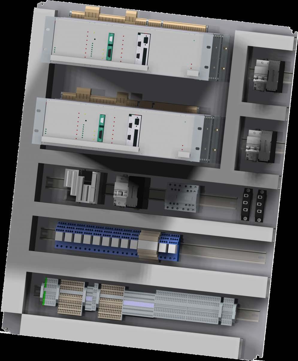
6 Of the mean The dual plate D630 allows a changeover from an AVR to a second one, even if the generator is running. To ensure this changeover, different elements are in place: The D630 AVRs exchange information from a CAN Bus, A small box with buttons and lights to Pilot in local mode the switching between two AVRs, Indicate the operating state of each AVR Three separated 24Vcc power supply : one for each AVR and one for the command circuit (relays and PLC) One PLC to : Have a "third vision" of the AVRs statement Pilot the changeover in case of the regulation mode is discordant between both AVRs. Inform, with dry contacts, the operating state of AVRs Two contactors allow switching the field circuit of the generator. Two diode modules, connected in the field circuit, to have it never opened. Page 4 / 32
7 All piloting such as: Regulation mode (voltage, power factor, VAr, Volt matching mode, manual mode) Ramp start, Corrections of the settings with digital inputs upper and lower Are present simultaneously on both AVRs. For the regulation modes, they are also monitored by the PLC. They are 4 modes of running for each AVR: Active : The AVR is running and pilot the field current of the generator, Waiting: The AVR is waiting and ready, its regulation mode is the same as the active regulator. It not pilots the field current. Maintenance: The AVR is stopped, for example for maintenance or to be replaced. Fault: The AVR is stopped due to an issue Technical specifications Plate equipped with two regulators for generators, with regulation modes: voltage, power factor, volt matching mode, VAr. Voltage sensing of the generator (according the reference mounted on the plate): 100/115Vac 50Hz, 100/130Vac 60Hz 380/420Vac 50Hz, 380/450Vac 60Hz Power supply (270Vac maximum) according the reference mounted on the plate, Shunt + Booster = power transformers AREP = auxiliaries windings PMG Auxiliaries power supply : 250Vac max 50/60HZ 24Vcc - 2A max each Field current : 10A rated, 20A maximum during 10s for 5Ω minimum Accuracy of the regulation: ±0.5% of the average of the three phases, with linear charges, without droop Voltage setting range: ±10% of the rated voltage, by dry contacts or external potentiometer (optional) Droop setting range: 0-10% of the rated voltage, at P.F=0 Under-speed protection : included, threshold settable, slope settable for V/Hz at 3V/Hz Field current ceiling : permanent at 110% of the rated field current Environment: maximum ambient conditions -10 C to +50 C, panel mounting without excessive vibrations. Setting of the AVRs with the SUPD600 supervisor, included with the plate. Sizes: Height : 750mm Width : 750mm Depth : 387.5mm Mass : 34.4kg Fixing : Schematics next page Page 5 / 32
8 1.4. Devices and general safety instructions Protection of the mean Auxiliary power supplies 24Vcc for both AVRs and command circuit are protected by breaker 2A, AVRs D630 are equipped with breakers 20A to protect the power supply circuit Spring terminal used can be equipped with optional accessories for measurement Personal safety Before starting your generator with the dual plate, this installation and maintenance manual must be read. All operations and interruption to do for using this plate must be done by authorized personnel. Our customer support is at your disposal to give you all information you need. The different operations described in this manual are accompanied by recommendations or symbols to make each operator aware of the risks. You must absolutely understand and respect the safety instructions below: Page 6 / 32

9 Safety instruction for an operation capable of damaging or destroying the machine or surrounding equipment. Safety instruction for an operation with electrical risk for the operator : 2. Installation instructions 2.1. Development of the panel for the dual plate Mounting must be vertical, and an area free of obstructions of 50mm must be respected around the plate. A ventilation, a cooling or heating system will be installed in the panel to maintain the plate in environmental limits described above Terminal blocks Terminal blocks of the plate are separated according to their use: X6 : Contacts for regulation modes X7 : Contacts for plate statement X3 : Exciter X5: Contacts alarm, fault, and information AVR2 X2: Measures and power AVR 1 X4: Contacts alarm, fault, and information AVR1 X1: Auxiliary power supplies 250Vac max X3: Measures and power AVR 2 Terminal blocks X2 and X4, corresponding to measure and power circuits of AVR1 and AVR2. Disconnect terminals are used. Page 7 / 32
10 DO NOT OPEN THESES DISCONNECT TERMINALS WHEN THE AVR IS IN "ACTIVE" MODE 2.3. Consumption Auxiliary supplies 250Vac max / 2A maximum each Exciter power supply : 270Vac max / 20A maximum Generator voltage sensing and mains voltage sensing: voltage according to Generator I/O block of the AVR, 0.75A maximum for each phase. Stator current measure : 1A 2.4. Wiring procedure For an AVR wired with not shielded wires, the maximum distance is 30m. Beyond this distance, shielded wires must be used. The maximum distance is 100m. The ohmic value of the wires for the exciter circuit (go and go back) must not exceed 5% of the resistance of the exciter, whatever the length of the wire. This allows to not oversize the power system for excitation (AREP, PMG, and shunt) The ohmic value of the wires for the excitation system must not exceed 5% of the resistance of the exciter, whatever the length of the wire. This allows to not oversize the power system for excitation (AREP, PMG, and shunt). The ohmic value of the wires for the droop current transformer (go and go back) must not exceed 1 ohm, whatever the length of the wire. This allows to not oversize the power of the droop current transformer. The ohmic value of the wires for the generator sensing or the mains sensing (go and go back) must not exceed 1 ohm, whatever the length of the wire. This allows to not oversize the voltage transformers. For information: Resistance per unit length up to 20 C for copper cables in ohms / km Section (mm²) Resistance (Ω/km) 1,5 13,3 2,5 7,98 4 4,95 6 3,3 10 1,91 Page 8 / 32
11 Sample: For an exciter of 10 ohms Maximum resistance of the wires = 0.5 ohms (2x0,25 ohms) Section according to the distance between the AVR and the generator : Distance (m) Section (mm²) 30 2, In case of shielded wires, we prefer the shield connection to ground dual plate side. The connection will be as close as possible to the plate and without loop. The alternator, regulator and shield should have an equipotential ground Handling This plate mass is 23kg. Its gravity center, as shown in the plan below, is placed very high compared to the center of the plate. Accordingly, means should be taken adequately for its implementation in the control panel. DO NOT HANDLE BY ARVS 3. Settings instructions 3.1. Transformer for stator current measure Droop CT TI To have a good running of the plate, it's necessary that stator current measure arrives from the same phase for both AVRs. Indeed, for generators with unbalanced load, using two different phases can affect the measure and induce a bump in the regulation when changeover from one AVR to the other occurs. For generators where one stator current transformer is used, it's necessary to use isolating current transformers for each AVR Configuration files The configuration of both AVRs must be identical and correspond to the technical and electrical data of the generator where the plate is going to be installed. Isolating CT TI AVR1 Plate Isolating CT TI AVR2 Page 9 / 32
12 So, it's important to verify particularly the settings of: Rated power, rated voltage, frequency and power factor of the alternator Voltage transformer for Generator voltage sensing, Voltage transformer for Mains voltage sensing, Current transformer for stator current measure, Values for the set points (voltage, power factor, VAr according to the application) and values for all the corrections applied (push buttons, potentiometers etc.) Values of PID coefficients, Limitations, Inputs and outputs configuration. CARREFUL DO NOT ERASE THE CONFIGURATION OF AN AVR WITH THE CONFIGURATION OF THE OTHER AVR Controls before the commissioning The first need is to control the external wiring and the general running of the plate. Step 1: Realize and control the wiring of the plate, accordingly with the schematics given with the plate and eventually the generator. Step2: Supply the AVRs and the command circuit with 250VAc power supply. Verify that: Both AVRs are turned on and running: The watchdog DEL is blinking DELs of the redundant card of the AVR are on The PLC is correctly powered and running (DEL fault is not turned on) Step 3: Verify that both AVRs are in "redundancy" mode with: One AVR in "active" mode The second AVR in "waiting" mode Note: The redundancy card taken in account in the AVR can be seen in the SupD600 supervisor on the home page (presence of 4 DEL showing the AVR statement: "Active", "Waiting", "Maintenance" or "Fault" Page 10 / 32


13 For page "Excitation parameters" Step 4: Verify that the information for measure and power are on the AVRs Disconnect terminals for both AVRs are well closed Breakers for voltage sensing and power supply of the generator are closed in the generator terminal box. Verify that the "Starting ramp" contact is opened on both AVRs. Page 11 / 32
14 3.4. Alignment of measures Once the previous controls are done, it's necessary to verify that the values of measures on both AVRs are similar. For that, it's necessary to use two points of load with the generator and control the measures with the main page of the SupD600. Step 1: Start the generator Start the generator at rated speed, Excite the machine, closing the starting ramp contact (or closing the power supply contactor if the "start on threshold" is selected in the configuration). The ramp-up must be performed without runaway to the voltage set point. Control that both AVRs are running with supervisor. Step 2: The "active" AVR will be the reference for measures of voltage and current. So, the accuracy of its measures should be compared with eventual customer devices present in the power plant (measure of voltage, current, power factor etc.) Step 3: Voltage measure alignment Do not apply load on the machine Verify the voltage measure for the generator on both AVRs with the supervisor, connecting successively on both. If the voltage of the "waiting" AVR is wrong (±1% of the voltage of the AVR "active"), correct modifying the values of the primary or secondary value of the sensing voltage transformer (General machine parameters) Step 4: Stator current alignment Apply if possible a load representing almost 25% of the rated power of the generator (this operation can be done in voltage, power factor or VAr mode) Verify the current stator measure Verify the current stator measure on both AVRs with the supervisor, connecting successively on both. If the current of the "waiting" AVR is wrong (±1% of the voltage of the AVR "active"), correct modifying the values of the primary or secondary value of the current transformer or/and isolating transformer (General machine parameters) Step 5: Power factor measure alignment With the same load, verify the measure of the power factor on the "waiting" AVR. If the measure is wrong (±0.01 of the "active" AVR), correct modifying the "Phase difference offset CT" (Page administrator) Step 6: Remove the load, Stop the excitation and the generator Setting of the redundancy values Two values must be set in the AVRs for the redundancy: Redundancy delay (Tr): settable between 0 and 1000ms. This temporization defines the PWM value that you consider as good in normal regulation running conditions, and that you want to transmit to the "waiting" AVR when an issue occurs on the "active" AVR. This value is set according to the reaction delay of the generator. Page 12 / 32

15 Channel switch delay (Tb): settable between 0 and 1000ms, but naturally below the redundancy delay. It corresponds to the delay during which the value of the PWM at "Tr" is applied before the "waiting" AVR becomes "active". Fault t PWM t Regulation AVR1 AVR2 t Tr Tb 3.6. Commissioning Once all the controls and settings are realized, turn on the generator. Note: At the end of all the settings and the plate commissioning, save the configuration of each AVR. 4. Using instructions This plate has been developed to switch automatically from an "active" AVR1 to a "waiting" AVR2, if an issue occurs on AVR1. A manual changeover with local push buttons is also possible Security instructions Before all operation on the plate, please refer to the running instruction and ensure that operations are realized accordingly with security of chapter 1.4. Page 13 / 32
16 4.2. Description of control devices and signalization Local push buttons There are 4 push buttons to switch manually from an AVR 1 "active" to an AVR 2 "waiting" to do eventually maintenance operations on it. Button "Maintenance" of AVR 1 (switch to "Maintenance" mode) Button "Maintenance" of AVR 2 (switch to "Maintenance" mode) Button "Reset maintenance" of AVR 1 (switch from "maintenance" to "waiting") Button "Reset maintenance" of AVR 2 (switch from "maintenance" to "waiting") Signalization The plate is also equipped with 9 lights, whose statement is copied on dry contacts: AVR1 "active" AVR1 "waiting" AVR1 "maintenance" AVR1 "fault" AVR2 "active" AVR2 "waiting" AVR2 "maintenance" AVR2 "fault" PLC "fault" 4.3. Description of running modes Switch with push buttons As previously said, it's possible to switch manually the AVR mode with local push buttons. In this case the operations are: Page 14 / 32

17 Note: It's not possible to change AVR 1 from "Active" mode to "Maintenance" mode if the regulation is running and if AVR 2 is in "Maintenance" mode or "Fault" Corrections of set-points with digital inputs cases The set-point corrections are copied from the "Active" AVR to "Waiting" AVR by CAN bus, only if they are realized with digital inputs. The regulation context is then conserved in case of changeover Follower The correction value of the field current given by the follower is copied from the "Active" AVR to the "Waiting" AVR by CAN bus. The regulation context is then conserved in case of changeover and if the AVR runs in manual mode Changeover on fault cases Several faults can lead to change the regulation from the AVR from "Active" to "Waiting" A loss of sensing on the "Active" AVR and not on the "Waiting" AVR, A loss of stator current measure on the "Active" AVR, An issue in the control loop of the power transistor A discordant mode between the PLC and the "Active" AVR (power factor, VAr, volt matching mode, manual mode) If the AVR breaker opens during a regulation mode. Page 15 / 32

18 Loss of sensing The loss of sensing on the generator is monitored during all the running If the loss of sensing is detected In case the loss of sensing is detected for both AVRs "active" and "waiting", then the changeover doesn't occur (that can come from the sensing voltage transformer or wiring in the machine). Note: if the loss of sensing occurs before both AVRs, the active AVR keeps the field current at the previous value and gives the information of loss of sensing. Then, it's possible to switch in manual mode and pilot the field current directly with push buttons (careful, when switching from automatic to manual, to be bumpless, the follower must be active) Nota2: In case both AVRs are in manual mode, the loss of sensing is not monitored. Page 16 / 32
19 Stator current The stator current measured by the AVR is compared permanently with the current measured by the waiting AVR, when the ramp is ended. In case the value measure by the "Active" AVR is less than 80% of the current measured by the "Waiting" AVR, the "Active" AVR go to "Fault" and the "Waiting" AVR go to "Active" mode Failure of the power transistor The AVR is equipped with a monitoring circuit of the power transistor. In case there is discordance between the command of the power transistor and its output, the "Active" AVR go to "Fault" and the "Waiting" AVR go to "Active" mode Page 17 / 32

20 Watchdog and CAN Bus Several data are exchanged between AVRs: The communication CAN bus allows to the "Waiting" AVR to have the running context for the "Active" AVR, The watchdog information is also exchanged between both AVRs to control each other. In case the watchdog or CAN bus in on fault, the "Waiting" AVR becomes "Active" if the fault is confirmed by a watchdog information lack. Page 18 / 32
21 Regulation mode This failure is controlled by the PLC. That allows verifying that the regulation mode defined on the generator is well taken in account by the active AVR. In case of discordance, the "Active" AVR go to "Fault" and the "Waiting" AVR go to "Active" mode. Power factor regulation mode Page 19 / 32
22 VAr regulation mode Page 20 / 32
23 Volt matching mode Page 21 / 32
24 Manual mode Page 22 / 32

25 Power breaker of the AVR opened The power breaker of the AVR is monitored by the PLC: if a regulation is running and the breaker of the "Active" AVR is opened, the "Active" AVR go to "Fault" and the "Waiting" AVR go to "Active" mode Procedure to replace a faulty AVR If an AVR is faulty, it's necessary to replace it, following the next steps: Step 1: Isolate the AVR Open the power disconnect terminals, Open the measure disconnect terminals, Stop the 24Vcc power supply which supply the AVR concerned Step 2: Remove the AVR Remove the wiring for connectors J2 and J3 and redundancy card Remove the wiring on the terminals on the top of the AVR CARREFUL: Even if there is no voltage present in case the AVR is in "Maintenance" or "Fault" statement, isolate both wires of the exciter terminals (terminals 5 and 6 of the AVR). Step 3: Remove the faulty AVR mechanically. Page 23 / 32
26 Step 4 : Install the spare AVR Ensure that the AVR is correctly fixed on the plate. Step 5 : Electrical wiring Wire the AVR, according strictly to the schematics of the plate. CARREFUL: An invert of wires can damage the AVR or the generator Wire the connectors of the supply card of the AVR, J2 and J3, Wire the connectors of the redundancy card. Step 6: Supply the AVR Switch on the power supply 24Vcc for the supply of the AVR Verify the AVR is running Step 7: Load the configuration of the AVR with the saved configuration (or if it's not possible, use the configuration of the "Active" AVR as a base) Note: Careful to change the serial number of the AVR in the "Regulator setting" page Step 8: Close the disconnect terminals Step 9: Controls Change the AVR status in "Maintenance" mode, pressing the push button "Maintenance" of the AVR concerned, Verify that the measures of the voltage and current are in the same range. If it's not the case, please refer to chapter 3.4. Press the button "Reset maintenance" of the AVR concerned, Verify that the AVR correctly change its mode from "Maintenance" to "Waiting" on the home page of the supervisor, Save the configuration file. Page 24 / 32
27 4.4. Defects and events Several defects can occur on the AVR, resulting its replacement. These faults are listed in the tab below: DEFECTS CAUSES CURE RESTART Loss of sensing fault Generator voltage transformer for sensing fault Replace of the faulty voltage transformer Stop the generator and initialize the running. Internal AVR voltage transformer for sensing fault Replace the AVR Restart the plate with procedure of the chapter AVR power transistor in short-circuit Transistor fault or exciter circuit opened which has generated an over voltage on the transistor Replace the AVR Restart the plate with procedure of the chapter Fault of the power supply 24Vcc of one AVR Power supply 24V faulty Replace the 24V power supply Restart the 24V power supply and verification of functionalities Fault of the converter on the power supply card of the AVR Replace the power supply card of the AVR Restart the plate with procedure of the chapter Fault of the power supply 24Vcc for the PLC and command Microcontroller card fault General fault of the plate Failure of the component Replace the 24V power supply Replace the AVR Restart the 24V power supply and verification of functionalities Restart the plate with procedure of the chapter Internal AVR droop Resistance fault Over current or component fault Replace the AVR Restart the plate with procedure of the chapter The AVR is in "fault" when "Waiting" mode is commanded One condition is not good to have the AVR in "Waiting" mode Verify that the breaker is closed and disconnect terminals are closed, and connectors are correctly inserted Restart the plate with procedure of the chapter An AVR doesn't change its mode when a local push button is pressed The analog output of the PLC is faulty Replace the analogic card of the PLC Restart the plate with procedure of the chapter The "Waiting" AVR is on fault when "Active" mode is commanded CAN Bus is on fault between both AVRs The stator current measure is in fault Verify that the DEL "CAN" of both AVRs is lightened Verify that the current is correct on the "waiting" AVR Restart the plate with procedure of the chapter Restart the plate after control of the measure with supervisor Page 25 / 32
28 5. Maintenance instructions 5.1. Technical data Mechanical schematic The board layout of the dual plate D630 is available under reference P on request to MOTEURS LEROY SOMER Orléans Electrical schematic The electrical schematic of the dual plate D630 is available under reference S on request to MOTEURS LEROY SOMER Orléans 5.2. Preventive maintenance instructions No maintenance is necessary on the plate. Page 26 / 32
29 Intentionally left blank Page 27 / 32
30 Intentionally left blank Page 28 / 32
31 Intentionally left blank Page 29 / 32
32 MOTEURS LEROY-SOMER ANGOULEME CEDEX-FRANCE
D700 Digital voltage regulator
 D700 Digital voltage regulator Installation and maintenance Table of contents 0. TERMS AND EXPRESSIONS... 6 1. General Instructions... 7 1.1. Identity sheet... 7 1.2. General overview of the product...
UNITROL 1000 Compact Automatic Voltage Regulator for small synchronous machines UNITROL
 UNITROL 1000 Compact Automatic Voltage Regulator for small synchronous machines UNITROL 1000-7 Copyright 2000 Photodisc, Inc. 5973-04 Applications of UNITROL 1000-7 UNITROL 1000-7 is the latest and most
ACOPOSinverter P74. User's Manual. Version: 2.20 (August 2016) Model no.: Original instruction
 Model no.: Original instruction") ACOPOSinverter P74 User's Manual Version: 2.20 (August 2016) Model no.: MAACPIP74-ENG Original instruction All information contained in this manual is current as of its creation/publication. We reserve
ACOPOSinverter P74 User's Manual Version: 2.20 (August 2016) Model no.: MAACPIP74-ENG Original instruction All information contained in this manual is current as of its creation/publication. We reserve
Before powering on your driver, read this manual thoroughly. If you have any doubt or suggestion, please do not hesitate to contact us!
 Laser diode driver Datasheet & UserManual Before powering on your driver, read this manual thoroughly. If you have any doubt or suggestion, please do not hesitate to contact us!, 37 Sedova St, Off 209,
Easy To Use OEMS Take Note
 MA7200 Features Sensorless Vector Precise speed and torque control for the most demanding system performance. Simple set-up through autotuning function. The MA7200 can be operated in sensorless vector
SORDS ELECTRIC ~ MA7200. Sensorless Vector AC Inverter.
 www.sordselectric.com MA7200 Sensorless Vector AC Inverter Features and Benefits Sensorless Vector The MA7200 has precise speed and torque control for the most demanding system performance and simple set-up
DGSZV-EP DIGITAL GALVANIC LONGITUDINAL DIFFERENTIAL PROTECTION. Application field
 DGSZV-EP DIGITAL GALVANIC LONGITUDINAL DIFFERENTIAL PROTECTION The digital galvanic longitudinal differential protection of type DGSZV-EP is part of device family named EuroProt. This short description
HERCULES-5000 INSTRUCTION MANUAL
 IndustrieAlpine Allee 1 D - 94513 Schönberg Tel.:+49 (0) 85 54/9609-0 Fax:+49 (0) 85 54/96 09 20 Mail: sales@tetelectronics.de INSTRUCTION MANUAL HERCULES-5000 High-performance power supplies Page 1 von
PGR-6101 MANUAL GROUND-FAULT & INSULATION MONITOR
 Tel: +1-800-832-3873 E-mail: techline@littelfuse.com www.littelfuse.com PGR-6101 MANUAL GROUND-FAULT & INSULATION MONITOR Revision 0-C-041918 Copyright 2018 by Littelfuse, Inc. All rights reserved. Document
Caterpillar Digital Voltage Regulator (CDVR) Introduction and Specifications
 Introduction and Specifications") Caterpillar Digital Voltage Regulator (CDVR) Introduction and Specifications Prepared by Service Training https://psmktg.cat.com/srvtrng/ Foreword This presentation was prepared by Caterpillar Service
Caterpillar Digital Voltage Regulator (CDVR) Introduction and Specifications Prepared by Service Training https://psmktg.cat.com/srvtrng/ Foreword This presentation was prepared by Caterpillar Service
QUICK START GUIDE. vau4/3. Frequency converter. operating instructions /12
 operating instructions QUICK START GUIDE Frequency converter vau4/3 28100241101 12/12 1 Safety information Warning of electrical shock! Danger to life! Electrical shock can cause serious injury or even
manufactured by SF8150-ZIF14
 manufactured by manufactured by SF8150- ZIF14 Butterfly packaged laser diode controller Datasheet & Users Manual Before powering on your driver, read this manual thoroughly. If you have any doubt or suggestion,
DECS-250 Digital Excitation Control System
 DECS-250 Digital Excitation Control System Basler Electric's DECS-250 digital excitation control system offers high performance, high flexibility, and extreme reliability for brushless excited AC synchronous
PGR-4700 MANUAL SENSITIVE GROUND-FAULT RELAY
 Tel: +1-800-832-3873 E-mail: techline@littelfuse.com www.littelfuse.com/pgr-4700 PGR-4700 MANUAL SENSITIVE GROUND-FAULT RELAY REVISION 2-B-032218 Copyright 2018 by Littelfuse, Inc. All rights reserved.
POSITION MONITOR USERS MANUAL POM-M2 / POM-M3. Content
 POM-M2 POM-M3 POSITION MONITOR USERS MANUAL Content 1 TECHNICAL SPECIFICATION... 2 2 DESCRIPTION... 2 3 HANDLING... 3 3.1 Calibration... 3 3.2 Limit setting... 3 4 CONNECTION... 4 4.1 K1 Power supply...
Chassis Power Supplies
 PDC24 / PAC Chassis Power Supplies (PDC24 / PAC) Issue 3 October 2005 INTRODUCTION PURPOSE Two Power Supply Units (PSUs) provide a dual-redundant source of 5.4Vand 12Vdc onto the backplane for the modules
2. Control Pin Functions and Applications
 IMARY CONTROL ( PIN) Module Enable / Disable. The module can be disabled by pulling the below 2.3 V with respect to the Input. This should be done with an open-collector transistor, relay, or optocoupler.
Electrical Demand Specification (Reference SOP: )
") Project: Equipment Description: Location: Equipment No.: Project No: Protocol No.: Content Index 1. GENERAL...3 Design Standards...3 1.1. Standards...3 2. DESIGN...3 2.1. Safety...3 2.2. Circuit protection...3
Project: Equipment Description: Location: Equipment No.: Project No: Protocol No.: Content Index 1. GENERAL...3 Design Standards...3 1.1. Standards...3 2. DESIGN...3 2.1. Safety...3 2.2. Circuit protection...3
QUALITY POWER SOLUTIONS BACKED UP BY REAL-WORLD ENGINEERING EXPERIENCE
 QUALITY POWER SOLUTIONS BACKED UP BY REAL-WORLD ENGINEERING EXPERIENCE User s Manual SR250HL Power Supply/ Float Charger for Lead Acid Batteries STANDARD FEATURES OPTIONAL FEATURES 3 Relay Alarms-Form
Operating instructions. Speed monitor D / / 2014
 Operating instructions Speed monitor D200 80005257 / 00 05 / 2014 Contents 1 Preliminary note...4 1.1 Symbols used...4 1.2 Warning signs used...4 2 Safety instructions...5 2.1 General...5 2.2 Target group...5
Operating Instructions Differential Pressure Transducer PS27
 Operating Instructions Differential Pressure Transducer PS27 halstrup-walcher GmbH Stegener Straße 10 79199 Kirchzarten/Germany Phone: +49 (0) 76 61/39 63 0 Fax: +49 (0) 76 61/39 63 99 E-mail: info@halstrup-walcher.com
AIR COOLED MODULAR RECTIFIER
 CONTROLLED POWER COMPANY SPECIFICATIONS AIR COOLED MODULAR RECTIFIER Spc1800a1 5JAN1999 SPECIFICATION S-1800-A MODULAR (REMOVABLE AND NON-REMOVABLE MODULES) AIR COOLED RECTIFIER Standard output power range:
Vector Drive - Troubleshooting Guide
 Haas Technical Documentation Vector Drive - Troubleshooting Guide Scan code to get the latest version of this document Translation Available The Haas Vector drive is the source of power for the spindle
MAINTENANCE MANUAL. EDACS REDUNDANT POWER SUPPLY SYSTEM 350A1441P1 and P2 POWER MODULE CHASSIS 350A1441P3, P4, AND P5 POWER MODULES TABLE OF CONTENTS
 MAINTENANCE MANUAL EDACS REDUNDANT POWER SUPPLY SYSTEM 350A1441P1 and P2 POWER MODULE CHASSIS 350A1441P3, P4, AND P5 POWER MODULES TABLE OF CONTENTS SPECIFICATIONS*... 2 INTRODUCTION... 3 DESCRIPTION...
This Datasheet for the IC660BBD025. Block 5/12/24Vdc Sink I/O 32 Circuits.
 This Datasheet for the IC0BBD02 Block /12/24Vdc Sink I/O 32 Circuits http://www.qualitrol.com/shop/p-14433-ic0bbd02.aspx Provides the wiring diagrams and installation guidelines for this GE Series 0-30
UNT1100 Series. Binary Output Jumpers AO2 AO1 AO3 AO4 AOCM AOCM AOCM AOCM AO1. AI Switches Job Information N2 Address. Ref N2+ N2- ADDR 0 = ALL OPEN
 1 2 8 4 AI6 R R Installation Bulletin UNT1100 Issue Date 0309 UNT1100 Series Introduction The Unitary (UNT) controller (UNT1100 Series) is a digital controller with applications for air handling units,
Phase comparator. User manual Document version: 02i00 Update:
 Phase comparator User manual Document version: 02i00 Update: 2015-03-13 Safety information When the device is in operation some of its parts may be connected to a hazardous live voltage. Improper operation
Buffered Power Supply PS-30DR v1.0
 Roger Access Control System Buffered Power Supply PS-30DR v1.0 Document version: Rev. C Firmware: 1.0.4 1. PRODUCT DESCRIPTION The PS-30DR is dedicated for electronic equipment which require 12VDC buffered
Solid State Remote Power Controller E /627
 Solid State Remote Power Controller E--623/62 Description The E-T-A Solid State Remote Power Controllers E--623/62 are electronic control modules suitable for inductive loads such as electromagnetic valves
Drive Technology \ Drive Automation \ System Integration \ Services. Manual. Control Cabinet Inverter MOVITRAC B Functional Safety
 Drive Technology \ Drive Automation \ System Integration \ Services Manual Control Cabinet Inverter MOVITRAC B Functional Safety Edition 05/2009 16811216 / EN SEW-EURODRIVE Driving the world Content Content
MSR Level Control Relay Module Operating Instructions for Level Control Relay Module Model: MSR
 Operating Instructions for Level Control Relay Module Model: MSR MSR Operation Instructions Rev. Apr 07 Page 1/8 1. Note Please read and take note of these operating instructions before unpacking and commissioning.
D115 The Fast Optimal Servo Amplifier For Brush, Brushless, Voice Coil Servo Motors
 D115 The Fast Optimal Servo Amplifier For Brush, Brushless, Voice Coil Servo Motors Ron Boe 5/15/2014 This user guide details the servo drives capabilities and physical interfaces. Users will be able to
ATV32HU11M2437 variable speed drive ATV32-1.1kW 200V - 1P - Bluetooth built-in - w heat sink
 Characteristics variable speed drive ATV32-1.1kW 200V - 1P - Bluetooth built-in - w heat sink Main Range of product Altivar 32 Product or component type Product destination Product specific application
PGR-6100 MANUAL GROUND-FAULT & INSULATION MONITOR
 Tel: +1-800-832-3873 E-mail: techline@littelfuse.com www.littelfuse.com/pgr-6100 PGR-6100 MANUAL GROUND-FAULT & INSULATION MONITOR Revision 2-C-050818 Copyright 2018 Littelfuse All rights reserved. Document
Operation Manual Series W-500
 Operation Manual Series W-500 Table of Content 1 Safety information... 2 1.1 Place of application of the unit... 2 1.2 Instructions for installation... 3 2 Start-up and adjustment of controller 4 3 General
ADC7520 SERIES. 1600W Battery Chargers and Power Supplies
 ADC7520 SERIES 1600W Battery Chargers and Power Supplies Wide output adjustment range 0 72VDC Analog control by external 0-5VDC voltage Temp.comp charging, sense as on option Power fail relay alarm Master-Slave
ICS Regent. Guarded Analog Output Modules. 4 to 20 ma (T3480) PD-6026
 PD-6026") ICS Regent PD-6026 Guarded Analog Output Modules 4 to 20 ma (T3480) Issue 1, March, 06 Guarded analog output modules provide 4 to 20 ma current outputs for a maximum of six user loads per module. These
ICS Regent PD-6026 Guarded Analog Output Modules 4 to 20 ma (T3480) Issue 1, March, 06 Guarded analog output modules provide 4 to 20 ma current outputs for a maximum of six user loads per module. These
IO-PT4. Component identification. User safety and equipment protection guidelines. Unitronics Industrial Automation Systems 1
 IO-PT4 I/O Expansion Module 4 PT100 Inputs (-50 to 460 C) The IO-PT4 is an I/O expansion module that can be used in conjunction with specific Unitronics OPLC controllers. The module offers 4 PT100 inputs
ICS Regent. Monitored Digital Input Modules 24 VDC (T3411) PD-6031
 PD-6031") ICS Regent PD-6031 Monitored Digital Input Modules 24 VDC (T3411) Issue 1, March, 06 Monitored digital input modules provide input sensing for 16 field input devices. With a line monitor device installed
ICS Regent PD-6031 Monitored Digital Input Modules 24 VDC (T3411) Issue 1, March, 06 Monitored digital input modules provide input sensing for 16 field input devices. With a line monitor device installed
Operating Instructions. For. Level Control Module. Model SSR 1000
 Operating Instructions For Level Control Module Model SSR 1000 SSR Operation Instructions Rev. 1 Jan 01 Page 1/7 1. Note Please read and take note of these operating instructions before unpacking and commissioning.
Welcome to the safety functions configuration training module for ACS880 Cabinet-built industrial drives.
 Welcome to the safety functions configuration training module for ACS880 Cabinet-built industrial drives. 1 After viewing this presentation you will be able to describe: The functionality of cabinet-built
This Datasheet for the IC660BBA104. Block 115Vac/125Vdc Analog Current Source 4 Inputs / 2 Outputs
 This Datasheet for the IC660BBA104 Block 115Vac/125Vdc Analog Current Source 4 Inputs / 2 Outputs http://www.qualitrol.com/shop/p-14425-ic660bba104.aspx Provides the wiring diagrams and installation guidelines
Voltage Dip-Proofing Inverter
 Voltage Dip-Proofing Inverter DPI54S / 54L Series Models 120V & 208/230 50/60Hz Contents: Introduction...3 Theory of operation...3 Specifications...5 Up-time considerations...6 Installation Guide...7 Test
This Datasheet for the IC660BBD110. Block 115Vac Input 16 Circuits.
 This Datasheet for the IC660BBD110 Block 115Vac Input 16 Circuits http://www.cimtecautomation.com/parts/p-14435-ic660bbd110.aspx Provides the wiring diagrams and installation guidelines for this GE Series
Installation and Wiring
 Wiring 2 2 Plan for Safety Safety Techniques WARNING: Providing a safe operating environment for personnel and equipment is your responsibility and should be your primary goal during system planning and
V E1B Snap-in I/O Module
 V200-18-E1B Snap-in I/O Module The V200-18-E1B plugs directly into the back of compatible Unitronics OPLCs, creating a selfcontained PLC unit with a local I/O configuration. Features 16 isolated digital
V E2B Snap-in I/O Module
 V200-18-E2B Snap-in I/O Module The V200-18-E2B plugs directly into the back of compatible Unitronics OPLCs, creating a selfcontained PLC unit with a local I/O configuration. Features 16 isolated digital
Sigma XT Ancillary Board (K588)
") Sigma XT Ancillary Board (K588) Operation and Maintenance Manual Man-1095 Issue 04 October 2009 Index Section Page 1. Introduction... 3 2. Safety and mounting... 3 3. Technical specification... 4 4. Connecting
Sigma XT Ancillary Board (K588) Operation and Maintenance Manual Man-1095 Issue 04 October 2009 Index Section Page 1. Introduction... 3 2. Safety and mounting... 3 3. Technical specification... 4 4. Connecting
Monitoring technique. VARIMETER Voltage relay MK 9064N, MH 9064
 Monitoring technique VARIMETER Voltage relay MK 9064N, MH 9064 0269462 Your Advantages Preventive maintenance For better productivity Quicker fault locating Precise and reliable Min-, Max. value or window
This Datasheet for the IC660BBA026. Block 24/48Vdc Analog Current Source 6 Inputs.
 This Datasheet for the IC660BBA026 Block 24/48Vdc Analog Current Source 6 Inputs http://www.cimtecautomation.com/parts/p-14421-ic660bba026.aspx Provides the wiring diagrams and installation guidelines
Analog Output Module Installation Instructions
 Description The Analog Output Module is a component of Novar Controls Spectrum Refrigeration Control System. It produces a varying analog voltage signal to control proportional modulating devices. Control
MC 11 EB-2 Power supply cabinet with external bus, AC version
 MC 11 EB-2 Power supply cabinet with external bus, AC version USER/MAINTENANCE MANUAL 1 SLOT 0 SLOT 1 SLOT 2 SLOT 3 SLOT 4 SLOT 5 SLOT 6 SLOT 7 SLOT 8 SLOT 9 SLOT 10 SLOT 11 EB-2 (a) MC11 (b) (c) Figures
FP_D.5_EGAT_THE REVAMP OF PARTIAL UPGRADE EXCITATION CONTROL SYSTEM BY USING THE EGAT s INNOVATION (EGAT-AVR)
") FP_D.5_EGAT_THE REVAMP OF PARTIAL UPGRADE EXCITATION CONTROL SYSTEM BY USING THE EGAT s INNOVATION (EGAT-AVR) 1. ABSTRACT Mr.Vitsanu Phonphai, (EGAT) Email: vitsanu.p@egat.co.th Mr. Suwat Ratiwatcharakorn,
FP_D.5_EGAT_THE REVAMP OF PARTIAL UPGRADE EXCITATION CONTROL SYSTEM BY USING THE EGAT s INNOVATION (EGAT-AVR) 1. ABSTRACT Mr.Vitsanu Phonphai, (EGAT) Email: vitsanu.p@egat.co.th Mr. Suwat Ratiwatcharakorn,
This Datasheet for the IC660BBA101. Block 115Vac/125Vdc RTD Input 6 Channels.
 This Datasheet for the IC660BBA101 Block 115Vac/125Vdc RTD Input 6 Channels http://www.qualitrol.com/shop/p-14423-ic660bba101.aspx Provides the wiring diagrams and installation guidelines for this GE Series
Sigma Si. Extinguishant Status Unit (K , K , K , K , K , K , K , K )
") Sigma Si Extinguishant Status Unit (K91100055, K91100056, K91110055, K91110056, K91111055, K91111056, K91111355, K91111356) Operation and Maintenance Manual Man1089 Issue 07 June 2013 Index Section Page
Sigma Si Extinguishant Status Unit (K91100055, K91100056, K91110055, K91110056, K91111055, K91111056, K91111355, K91111356) Operation and Maintenance Manual Man1089 Issue 07 June 2013 Index Section Page
EX-RC1 Remote I/O Adapter
 EX-RC1 Remote I/O Adapter The EX-RC1 interfaces between Unitronics Vision OPLCs and remote I/O Expansion Modules distributed throughout your system. The adapter is connected to a PLC via CANbus. Each adapter
Data Sheet T 6493 EN. TROVIS 6400 Automation System TROVIS 6493 Compact Controller. For panel mounting (front frame 48 x 96 mm/1.89 x 3.
 Data Sheet T 6493 EN TROVIS 6400 Automation System TROVIS 6493 Compact Controller For panel mounting (front frame 48 x 96 mm/1.89 x 3.78 inch) Application Digital controller to automate industrial and
USER MANUAL VIBRATION CONTROL RMA-POWER-BOX 107/230
 USER MANUAL VIBRATION CONTROL Version 2.2 1 IMPORTANT NOTES Electrical danger within the meaning of this documentation or the warning labels on the product itself respectively means that death, serious
ASCO 920 Remote Control (RC) Switches
 Switches") Maximum reliability and excellent value ASCO 920 Remote Control (RC) Switches ASCO 920 Remote Control Switch in Type Enclosure The ASCO 920 is designed as a feeder disconnect switch for load capacities
Maximum reliability and excellent value ASCO 920 Remote Control (RC) Switches ASCO 920 Remote Control Switch in Type Enclosure The ASCO 920 is designed as a feeder disconnect switch for load capacities
PLC-24V10AL(-PT/-TH) Quick Start Manual (Rev.1.10)
 Quick Start Manual (Rev.1.10)") TEC (Peltier) Controller PLC-24V10AL(-PT/-TH) Quick Start Manual (Rev.1.10) Thank you for purchasing the TEC (Peltier) Controller PLC-24V10AL. Read these operating instructions carefully to ensure effective
TEC (Peltier) Controller PLC-24V10AL(-PT/-TH) Quick Start Manual (Rev.1.10) Thank you for purchasing the TEC (Peltier) Controller PLC-24V10AL. Read these operating instructions carefully to ensure effective
32-Channel Analogue Input Module Differential Input
 MAI32*AD 32-Channel Analogue Input Module Differential Input (MAI32*AD) Issue 4 October 2005 INTRODUCTION PURPOSE The Analogue Input Module provides up to 32, low voltage or current analogue input signals.
Operating instructions. Switching amplifier DN0210 DN / / 2015
 Operating instructions Switching amplifier DN0210 DN0220 UK 80011079 / 00 01 / 2015 Contents 1 Preliminary note...4 1.1 Symbols used...4 1.2 Warning signs used...4 2 Safety instructions...5 2.1 General...5
SSV-T and SSC-T High Drop-out Relay. Range amps amps amps amps. Operating Frequency: Temperature Error:
 41-766.7 SSV-T and SSC-T High Drop-out Relay device. A magnetic armature, to which leaf-spring mounted contacts are attached, is attracted to the magnetic core upon energization of the switch. When the
INSTALLATION MANUAL SLI 50 INVERTER
 INSTALLATION MANUAL SLI 50 INVERTER www.unipowerco.com Manual No. SLI-50-48-3 2016 UNIPOWER LLC All Rights Reserved UNIPOWER LLC 3900 Coral Ridge Drive, Coral Springs, Florida 33065, USA sales@unipowerco.com
GCI-5K INSTALLATION AND OPERATOR S MANUAL
 GCI-5K INSTALLATION AND OPERATOR S MANUAL Grid-tied inverter for wind Ningbo Ginlong Technologies 1 INTRODUCTION 2 SAFETY GUIDELINES AND WARNINGS 3 INSTALLATION 3.1 Selecting a location for the inverter
Language of the manual
 USER S MANUAL INSTALLATION AND Language of the manual Product English Single-phase switching power supply: 24V @ 1.5A Description Contents: 1.0 Disclaimer 2.0 Description and General features Page 2 2
ATV32HU75N4 variable speed drive ATV kw V - 3 phase - with heat sink
 Characteristics variable speed drive ATV32-7.5 kw - 400 V - 3 phase - with heat sink Main Range of product Altivar 32 Product or component type Product destination Product specific application Function
Sigma Si Weatherproof Extinguishant Status Unit (W911000W8, W911100W8, W911110W8, W911113W8)
") Sigma Si Weatherproof Extinguishant Status Unit (W911000W8, W911100W8, W911110W8, W911113W8) Operation and Maintenance Manual Man1097 Issue 02 October 2009 Index Page 1. Introduction... 3 2. Safety and
Sigma Si Weatherproof Extinguishant Status Unit (W911000W8, W911100W8, W911110W8, W911113W8) Operation and Maintenance Manual Man1097 Issue 02 October 2009 Index Page 1. Introduction... 3 2. Safety and
FLÄKTGROUP OFFERS A WIDE RANGE OF PER- MANENT MAGNET MOTORS (PM) AND FREQUENCY CONVERTERS FOR PLUG FANS. POWER RANGE IS FROM 0,8 KW TO 15 KW.
 AND FREQUENCY CONVERTERS FOR PLUG FANS. POWER RANGE IS FROM 0,8 KW TO 15 KW.") CENTRIFLOW PUR 3D (A, PLUG B, C, D) FAN GMPM FC101 AND SLIDE IN FREQUENCY ROTOR CASSETTE CONVERTER QUICK GUIDE FLÄKTGROUP OFFERS A WIDE RANGE OF PER- MANENT MAGNET MOTORS (PM) AND FREQUENCY CONVERTERS
CENTRIFLOW PUR 3D (A, PLUG B, C, D) FAN GMPM FC101 AND SLIDE IN FREQUENCY ROTOR CASSETTE CONVERTER QUICK GUIDE FLÄKTGROUP OFFERS A WIDE RANGE OF PER- MANENT MAGNET MOTORS (PM) AND FREQUENCY CONVERTERS
E1 Plus Electronic Overload Relay
 ROCKWELL AUTOMATION PROCUREMENT SPECIFICATION PROCUREMENT SPECIFICATION E1 Plus NOTICE: The specification guidelines in this document are intended to aid in the specification of products. Specific installations
HID. GE Consumer & Industrial Multilin. High Impedance Differential Module Instruction manual GEK Copyright 2005 GE Multilin
 g GE Consumer & Industrial Multilin HID High Impedance Differential Module Instruction manual GEK-113064 Copyright 2005 GE Multilin GE Multilin 215 Anderson Avenue L6E 1B3 Markham, ON -CANADA T (905) 294
ATV32H075M2 variable speed drive ATV32-0,75 kw V - 1 phase - with heat sink
 Characteristics variable speed drive ATV32-0,75 kw - 200 V - 1 phase - with heat sink Main Range of product Altivar 32 Product or component type Product destination Product specific application Function
Safegard V4 Panel. Installation Datasheet. Safegard V4 Panel Installation Instructions and Datasheet release 1.7 August 2016
 Safegard V4 Panel Installation Datasheet ELECTROSTATIC SENSITIVE DEVICE This product forms part of a life safety system. Failure to correctly store, handle, install and maintain the product will directly
Installation Job Aid for VSP 4850GTS
 Installation Job Aid for VSP 4850GTS Notices Release 6.1.0.0 NN46251-308 Issue 02.01 November 2017 Notice paragraphs alert you about issues that require your attention. The following paragraphs describe
SLATE. Digital I/O Module INSTALLATION INSTRUCTIONS R8001D4001
 SLATE Digital I/O Module R8001D4001 INSTALLATION INSTRUCTIONS Scan for more information Application SLATE brings configurable safety and programmable logic together into one single platform. The platform
PFC Mini TM Power Factor Corrected AC-DC Switchers
 21 PFC Mini TM Power Factor Corrected AC-DC Switchers Overview Technical Description The PFC Mini is an extremely low profile switching power supply that combines the advantages of power factor correction,
VARMECA. Data communication systems. Réf GB / a
 VARMECA Data communication systems Réf. 3427 GB - 2.33 / a - 07.01 The communication maestro A new networking solution VARMECA motors and geared motors, with integrated frequency inverter, offer a very
POWERDRIVE, PROXIDRIVE, VARMECA
 M AI4+ AI4-7 8 + Diff V - A/D 2 bits Analog input 4 level 5.4 Scaling 5.4 5.4 X - 5 In This manual is to be given to the end user AI5 V A/D bits Analog input 5 level 5.44 Scaling 5.45 X - I AO6 2 -V 4-2
SE-135 MANUAL GROUND-FAULT GROUND-CHECK MONITOR
 SE-135 MANUAL GROUND-FAULT GROUND-CHECK MONITOR AUGUST 14, 2001 REVISION 1 Publication: SE-135-M Document: S95-C135-00000 Printed in Canada. Copyright 2001 by Startco Engineering Ltd. All rights reserved.
Expansion Module HZS 541-1S
 Expansion Module HZS 541-1S 12.10.2015 Page 1 System Description The external HZS 541-1S expansion module provides users of biomass heating systems with additional 230 V AC relay outputs, analog inputs
SED2 Variable Frequency Drives Conventional Bypass (C-Bypass) Options
 Options") Submittal Sheet SED2 Variable Frequency Drives Conventional Bypass (C-Bypass) Options Description The Bypass Options are companion packages for the family of SED2 Variable Frequency Drives. For information
Submittal Sheet SED2 Variable Frequency Drives Conventional Bypass (C-Bypass) Options Description The Bypass Options are companion packages for the family of SED2 Variable Frequency Drives. For information
IO-DI8-TO8 I/O Expansion Module 8 Inputs, 8 Outputs
 IO-DI8-TO8 I/O Expansion Module 8 Inputs, 8 Outputs The IO-DI8-TO8 is an I/O expansion module that can be used in conjunction with specific Unitronics OPLC controllers. The module offers 8 digital inputs,
PowerFlex 40 Sample Specification
 PowerFlex 40 Sample Specification GENERAL REFERENCES REGULATORY REQUIREMENTS Designed to meet the following specifications: NFPA 70 - US National Electrical Code NEMA ICS 3.1 - Safety standards for Construction
EATON 5S 850/1200/1600
 www.eaton.com EATON 5S 850/1200/1600 Installation and user manual Packaging EATON 5S 1 2 3 5 Caution! l Before installing the Eaton 5S, read the booklet 3 containing the safety instructions to be respected.
Voltage Dip-Proofing Inverter
 Voltage Dip-Proofing Inverter DPI53S / 54L Series Models 120V & 208/230 50/60Hz LEADERS IN VOLTAGE DIP-PROOFING Contents: Introduction...3 Theory of operation...3 Specifications...5 Up-time considerations...6
The PCI Series. Precise power control for complex SCR applications. Phase Angle Fired SCR Power Controls AMPS VAC
 The PCI Series Phase Angle Fired SCR Power Controls 25-1200 AMPS 120-600 VAC Precise power control for complex SCR applications. ROBICON 1996 Distributed Worldwide by www.mcgoff-bethune.com Applications
Positive-guided relay outputs: 3 safety contacts (N/O), instantaneous. 1 auxiliary contact (N/C), instantaneous
, instantaneous. 1 auxiliary contact (N/C), instantaneous") Safety relay for monitoring E-STOP pushbuttons. Approvals Unit features Positive-guided relay outputs: 3 safety contacts (N/O), instantaneous 1 auxiliary contact (N/C), instantaneous Safe separation of
Safety relay for monitoring E-STOP pushbuttons. Approvals Unit features Positive-guided relay outputs: 3 safety contacts (N/O), instantaneous 1 auxiliary contact (N/C), instantaneous Safe separation of
EF-S1 SERIES. Continuously check invisible static electricity in lines. Constantly check static in lines!
 1215 PHOTO PHOTO SAFETY USE SERIES Related Information General terms and conditions... F- General precautions... P.1595 guide... P.1155~ MEASUREMENT panasonic.net/id/pidsx/global Continuously check invisible
Operating instructions Monitor FD-2 DR2005 DR / / 2007
 Operating instructions Monitor FD-2 DR2005 DR2006 UK 1 2 3 4 5 6 7 8 9 10 11 12 7390342 / 01 07 / 2007 CH1CH2 CH3CH4RUNPRGTST KEY 13 14 15 16 17 18 19 20 21 22 23 24 Content 1 Safety instructions...4 2
Non-communicating room controllers
 3 882 DESIGO RXA Non-communicating room controllers RXA29.1 For fan-coil systems The RXA29.1 room controller are used for temperature control in individual rooms. For 2-pipe or 4-pipe fan-coil systems,
NCH-1000 (Multiple Breaker Types) Installation Instructions
 Installation Instructions") 20M1 12345678 NCH-1000 (Multiple Breaker Types) Installation Instructions DOC. #560502100 C 7/30/04 PRINTED IN U.S.A. Regulatory Compliance Safety This device has been tested and found to be in compliance
20M1 12345678 NCH-1000 (Multiple Breaker Types) Installation Instructions DOC. #560502100 C 7/30/04 PRINTED IN U.S.A. Regulatory Compliance Safety This device has been tested and found to be in compliance
V E5B Snap-in I/O Module
 V200-18-E5B Snap-in I/O Module The V200-18-E5B plugs directly into the back of compatible Unitronics OPLCs, creating a selfcontained PLC unit with a local I/O configuration. Features 18 isolated digital
DECS-100 Digital Excitation Control System FEATURES. WINDOWS SOFTWARE Interface for setting and communicating with Basler products Request DECS-100-CD
 DECS-100 Digital Excitation Control System Basler Electric offers a high powered, low-cost digital excitation control system, the DECS-100. This environmentally rugged product is ideally suited for controlling
USER MANUAL MULTI COLOR TOUCH SCREEN PAPERLESS RECORDER TPLR-96 Series
 USER MANUAL MULTI COLOR TOUCH SCREEN PAPERLESS RECORDER TPLR-96 Series TEMPSEN DEVICES Plot No : 2&3, Balaji Nagar, 4 th Street, Mettukuppam, Thoraipakkam, Chennai-600097 Tele fax : +91-44-24581758,Mobil
E510. Compact Drive IP 20/ NEMA HP (230V) 1-75 HP (460V)
 1-75 HP (460V)") E510 Compact Drive IP 20/ NEMA 1 0.5-40 HP (230V) 1-75 HP (460V) Control Mode Application & Selection Guide The E510 compact AC Drive is an easily configurable product that controls many motor driven applications.
E510 Compact Drive IP 20/ NEMA 1 0.5-40 HP (230V) 1-75 HP (460V) Control Mode Application & Selection Guide The E510 compact AC Drive is an easily configurable product that controls many motor driven applications.
VAMP 221. Table of Contents
 2 V221/EN M/E019 VAMP 221 Table of Contents Table of Contents 1. General... 7 1.1. VAMP 221 arc protection system components... 7 1.1.1. Central unit VAMP 221... 9 1.1.2. I/O units VAM 12L / VAM 12 LD,
MP7. Uninterruptible Power Supply
 Uninterruptible Power Supply PRODUCT SPECIFICATIONS Description The industrial UPS provides your critical equipment with uninterruptible 3 phase AC power. Using high frequency dual conversion technology,
DT1102 V (PS) Fully Configurable Galvanic Isolator. Operating Instructions
 Fully Configurable Galvanic Isolator. Operating Instructions") (PS) Fully Configurable Galvanic Isolator Operating Instructions Contents 1. About this document...4 1.1. Function... 4 1.2. Target group... 4 1.3. Symbolism used... 4 2. For your safety...5 2.1. Authorized
(PS) Fully Configurable Galvanic Isolator Operating Instructions Contents 1. About this document...4 1.1. Function... 4 1.2. Target group... 4 1.3. Symbolism used... 4 2. For your safety...5 2.1. Authorized
Positive-guided relay outputs: 3 safety contacts (N/O), instantaneous. 1 auxiliary contact (N/C), instantaneous
, instantaneous. 1 auxiliary contact (N/C), instantaneous") Gertebild Bildunterschrift Two-hand control device for safety circuits Approvals Zulassungen Unit features Gertemerkmale Positive-guided relay outputs: 3 safety contacts (N/O), instantaneous 1 auxiliary
Gertebild Bildunterschrift Two-hand control device for safety circuits Approvals Zulassungen Unit features Gertemerkmale Positive-guided relay outputs: 3 safety contacts (N/O), instantaneous 1 auxiliary
Positive-guided relay outputs: 3 safety contacts (N/O), instantaneous. 1 auxiliary contact (N/C), instantaneous
, instantaneous. 1 auxiliary contact (N/C), instantaneous") Two-hand control unit for press controllers and safety circuits Approvals Unit features Positive-guided relay outputs: 3 safety contacts (N/O), instantaneous 1 auxiliary contact (N/C), instantaneous 1
Two-hand control unit for press controllers and safety circuits Approvals Unit features Positive-guided relay outputs: 3 safety contacts (N/O), instantaneous 1 auxiliary contact (N/C), instantaneous 1