UPS READY POWER DISTRIBUTION ASSEMBLY
|
|
|
- Melissa Matthews
- 5 years ago
- Views:
Transcription
1 UPS READY POWER DISTRIBUTION ASSEMBLY FOR TRAFFIC CABINETS with LED Signals INSTALLATION & OPERATOR S MANUAL VERSION 1.2 1
2 Note The instructions contained in this manual are not intended to cover all of the details or variations in equipment, or to provide for every possible contingency to be met in connection with installation, operation, or maintenance. Should further information be desired or should particular problems arise which are not covered sufficiently for the purchaser s purposes, the matter should be referred directly to Always On UPS Systems Inc. Any electrical or mechanical modifications to this equipment, without prior written consent of Always On UPS Systems Inc, will void all warranties. Unauthorized modifications also can result in personal injury, death, or destruction or the equipment. Power Distribution Assembly Please complete the Warranty Card supplied with this PDA and return it by mail to Always On UPS Systems Inc. This activates the warranty. If additional information or technical assistance is required call: Always On UPS Systems Inc Sales and Technical Support Line Toll-free at Ext. 451 or (250) Ext. 451 or Fax (250) Or sales@alwayson.com or visit our web site at Or write to: Always On UPS Systems Inc. Bldg Campion Road, Kelowna, BC, V1X 7S8, Canada Please complete the following information for your records. Model Number: Serial Number: Date of Installation: Inspected By: 2
3 IMPORTANT SAFETY INSTRUCTIONS THE PDA SYSTEM IS NOT INTENDED FOR EXTERNAL USE UNLESS SPECIFICALLY DESIGNED FOR IT. ALL SERVICING MUST BE DONE BY QUALIFIED PERSONNEL. DO NOT ATTEMPT TO SERVICE THIS EQUIPMENT YOURSELF. OPENING OR REMOVING COVERS WILL RISK EXPOSURE TO DANGEROUS VOLTAGES. DO NOT LOCATE PDA IN AN AREA WHERE UNAUTORIZED PERSONNEL HAVE ACCESS. THE POWER SUPPLY FOR THIS UNIT MUST BE SINGLE PHASE RATED IN ACCORDANCE WITH THE EQUIPMENT DATA PLATE. IT MUST BE SUITABLY GROUNDED. DO NOT STAND BEVERAGE CONTAINERS ON THE UNIT. THE POWER TERMINAL BLOCK ON THE PDA WILL BE LIVE WHEN THERE IS A UPS OR GENERATOR CONNECTED. QUALIFIED PERSONNEL SHOULD BE CONSULTED WHEN: LIQUID HAS BEEN SPILLED INTO THE UNIT THE UNIT DOES NOT OPERATE NORMALLY EVEN THOUGH THE OPERATING INSTRUCTIONS HAVE BEEN FOLLOWED DO NOT PLACE MAGNETIC STORAGE MEDIA ON TOP OF THE UNIT, AS THIS CAN RESULT IN DATA CORRUPTION. THIS PDA WAS DESIGNED FOR USE IN A TRAFFIC CABINET ONLY. ATTENTION: ALL REPAIRS SHOULD BE PERFORMED BY QUALIFIED SERVICE PERSONNEL. READ THIS MANUAL CAREFULLY BEFORE INSTALLING OR USING THE UNIT. FOLLOW ALL PROCEDURES, AS DESCRIBED, TO ENSURE SAFE, RELIABLE OPERATION OF THE PDA. SAVE THESE INSTRUCTIONS 3
4 MORE SAFETY INSTRUCTIONS DO NOT USE THIS EQUIPMENT FOR ANY PURPOSE OTHER THAN THE INTENDED USE. EXAMINE THE PACKAGING CONTAINER FOR DAMAGE. NOTIFY THE CARRIER IMMEDIATELY IF DAMAGE IS PRESENT. DO NOT DISASSEMBLE THE PDA. DO NOT OPERATE OR LOCATE NEAR WATER OR EXCESSIVE HUMIDITY. DO NOT USE OTHER MANUFACTURERS ACCESSORIES. MAY CAUSE DAMAGE OR UNSAFE CONDITIONS. KEEP LIQUID AND FOREIGN OBJECTS FROM GETTING INSIDE THE PDA. DO NOT PLACE OR OPERATE CLOSE TO GAS, HEATERS OR FIRE. DO NOT LET POWER CABLES CONTACT HOT SURFACES. THE POWER CONNECTIONS FOR THE PDA SHOULD BE WIRED IN ACCORDANCE WITH LOCAL AND NATIONAL ELECTRICAL CODE SPECIFICATIONS. ONCE THE PDA IS CONNECTED TO AN ENERGY SOURCE, SUCH AS THE BATTERIES, THE OUTPUT TERMINALS MAY BE LIVE EVEN WHEN THE PDA IS NOT CONNECTED TO AN AC SUPPLY, ESPECIALLY WHEN CONNECTED TO A UPS. SYMBOLS Protective grounding terminal; terminal must be connected to ground prior to making any other connection to the equipment. A terminal to or from which an alternating (sine wave) current or voltage may be applied or supplied. A terminal to or from which a direct current or voltage may be applied or supplied. This symbol indicates the word phase. May be used in lieu of the wording caution, risk of electric shock for any cautionary marking. 4
5 Table of Contents 1. PRODUCT DESCRIPTION SCHEMATIC DESCRIPTION OF OPERATION HANDLING DELIVERY INITIAL INSPECTION INSTALLATION INSTALLING INTO THE CABINET CONNECTING THE AC SUPPLY TO THE MAIN SERVICE ENTRANCE WIRING TO THE TERMINAL BLOCK OPERATION MAIN SERVICE ENTRANCE LOCATION & OPERATION FRONT PANEL LAYOUT TO TURN PDA OFF...ERROR! BOOKMARK NOT DEFINED TO TURN PDA ON...ERROR! BOOKMARK NOT DEFINED TO TURN OFF AN INDIVIDUAL CIRCUIT GENERATOR MODE / CONNECTING A GENERATOR (GENERATOR OPTION ONLY) PLACE PDA IN BYPASS, DISABLE OR AUTO MODE ( UPS READY OPTION ONLY) MAINTENANCE RESET A BREAKER FUSE REPLACEMENT SURGE SUPPRESSOR INSPECTIONS & REPLACEMENT OPTIONAL EXTRAS UPS (FOR UPS READY PDA) TECHNICAL DATA CONTACT INFORMATION ADDITIONAL PURCHASES OR UPGRADES QA / WARRANTY QUESTIONS SOFTWARE QUESTIONS
6 1. Product Description This Power Distribution Assembly (PDA) was designed as a UPS ready power supply for traffic cabinets. This power supply allows for easy connection of a UPS to the power supply and allows the UPS to be a detachable unit that may be added or removed from the panel at any time, without interruption of service to the traffic cabinet (when optional ATS installed). The panel is intended to be a power distribution panel with an optional main service entrance, along with more refined secondary protection for sensitive control circuits. Furthermore, the unit may be equipped with special features, such as a generator transfer switch, UPS power backup and conditioning, TVSS power conditioning and filtering or a wrap-around bypass for servicing the UPS or allowing the PDA to be UPS ready. These features are further described below. The main features of the panel are the optional main service entrance, the serviceable TVSS module and the conveniently accessed branch protection, all in a slim minimum footprint PDA. The TVSS module offers high protection that surpasses other similar products. Furthermore, the TVSS module offers power line conditioning to the traffic cabinet s sensitive equipment, regardless if a UPS is installed. As extra features, an automatic UPS sensing Bypass Module may be added to the PDA to allow for easy installation of a UPS or servicing of a UPS at any time without service interruption to the traffic cabinet. Also, there is a generator transfer switch option that allows the user to easily and safely connect a 20A, 120VAC generator to power the PDA and traffic cabinet at the flip of a switch. No need to perform unsafe jumpers. Optional service entrance breaker. 6
7 1.1. Schematic PDA Schematic 7
8 1.2. Description of Operation Optional Main Service Entrance: Allows connection of an AC Service to the traffic cabinet. Neutral is bonded to ground with a non-ferrous bonding screw. A 30A, 10kAIR breaker is installed as an optional feature. A 22kAIR breaker is available upon request. Generator Connection: Allows easy connection of a generator to the PDA with a 120VAC, 20A twist-lock dongle. Optional Generator Transfer Switch: Allows easy transfer from AC service to generator back up without back feeding the AC service. This break-before-make transfer switch also switches the neutral from the AC service to generator service. A 20A, 10kAIR magnetic circuit breaker is installed. Sub-distribution Auxiliary Circuits: The auxiliary circuits are unprotected by TVSS or UPS modules. These circuits are fed raw unfiltered AC from the AC service. All neutral connections of loads fed from auxiliary circuits are fed from the neutral bus N1. A 20A, 10kAIR magnetic circuit breaker is installed and each branch is equipped with supplementary fusing that is all accessible from the front panel. WARNING: ALL NEUTRAL CONNECTIONS OF LOADS FED FROM THE PROTECTED CIRCUITS ARE FED FROM THE NEUTRAL BUS N2 OR LOADS MAY NOT OPERATE PROPERLY OR DAMAGE MAY OCCUR. Sub-distribution Protected Circuits: The protected circuits are protected from surges and EMI by the TVSS/EMI module as standard and the UPS as an option. All neutral connections of loads fed from the protected circuits are fed from the neutral bus N2. A 15A, 10kAIR magnetic circuit breaker is installed and each branch is equipped with supplementary fusing that is all accessible from the front panel. WARNING: ALL NEUTRAL CONNECTIONS OF LOADS FED FROM AUXILIARY CIRCUITS ARE FED FROM THE NEUTRAL BUS N1 OR LOADS MAY NOT OPERATE PROPERLY OR DAMAGE MAY OCCUR. TVSS/EMI Module: The TVSS/EMI module filters transients from the raw AC service to add robust protection to the protected loads. 8
9 Surge Suppressor Modules: The surge suppressor modules complement the TVSS/EMI module by keeping high voltage transients such as lightning from ruining the protected loads. There are two stages of surge suppressor modules on either side of the TVSS/EMI module and are both serviceable and can be replaced if sacrificed during a transient event. The first stage is a gas tube arrestor that takes the brunt of a high voltage transient and is placed in front of the TVSS/EMI module. The second stage is a Varistor based surge suppressor that further protects the load while the gas tube arrestor works to reduce the voltage spike to a safe level. Automatic Maintenance Bypass (if equipped with UPS Ready option): The built in automatic bypass senses for a UPS and will switch automatically from maintenance bypass to UPS power without disruption to the load. The control switch also disables the bypass function or forces a bypass of the UPS. UPS Ready Connection (if equipped with UPS Ready option): A UPS connection can be made with an optional cable that provides AC and DC power to the UPS and also delivers AC power back to the PDA. This cable allows one to take full advantage of the UPS Ready PDA features. Mercury Contactor: A traffic rated mercury contactor is also installed as standard for operation with the signal bus. Supplementary Fusing: Provides secondary circuit protection for sensitive control circuitry. All fuses can be serviced conveniently from the front panel. 9
10 2. Handling 2.1. Delivery Upon receiving the PDA system, inspect the packaging integrity and the physical condition of the unit carefully. In the event that physical damage is visible, the carrier must be informed immediately and a claim filed with them. Inform Always On as soon as the claim has been filed and a copy of claim should be faxed to Always On at (250) A detailed report of the damage is necessary for carrier insurance claim Initial Inspection Unpack the system carefully, notice the packing method, and retain the box and packing material. If you must return the PDA at any time, you must repack it the way it was originally shipped. Visually inspect the PDA for damage that may have occurred during shipment. If there is damage, or anything is missing, contact the dealer from whom you purchased the unit, and save the packaging for future shipment. When the unit has passed the initial inspection, record the installation date in the space provided towards the front of this manual. 10
. The PDA should be wired in accordance with local and national electrical code specifications by qualified personnel.")
11 3. Installation The PDA is intended for installation in a temperature and humidity controlled environments, free of conductive contaminants with unrestricted airflow. Absolute maximum ambient temperature at sea level must not exceed 74ºC (165ºF). The PDA should be wired in accordance with local and national electrical code specifications by qualified personnel. Maintenance and Servicing of the PDA requires access to the front and side of the PDA. Provide the necessary free space to access the side panel of the PDA Installing into the Cabinet Mount the PDA to the Cabinet C-Channel through the holes provided at the top and the bottom of the PDA. Mounting Hole Locations 11

 cover must be removed. Once the cover is removed, the terminal lugs for the neutral bus, main breaker and service ground can be accessed.")
12 3.2. Wiring Connections Connecting the AC Supply to the PDA Connect the AC line to the protected and auxiliary breaker terminals. Connect the AC neutral to input neutral bus. Connect the ground wire to the ground bus Connecting the AC Supply to the Main Service Entrance (Optional) If the unit features an optional Main Service Entrance, to terminate the AC supply to the PDA, the Main Service Entrance (MSE) cover must be removed. Once the cover is removed, the terminal lugs for the neutral bus, main breaker and service ground can be accessed. Also, the neutral bus contains the bonding screw that bonds it to ground. Optional Main Service Entrance & Termination Locations 12
, the Heater (TB1-2), Lamp (TB1-3), Fan (TB1-4), and Aux (TB1-7) circuits.")
13 3.3 Wiring to the Terminal Block Load power terminations are to be made to terminal blocks TB1 & TB2. Remove the terminal block cover. The load neutral connects are to be made on N1 & N2. All loads that are designated Auxiliary and not Protected are to be connected to N1. This includes the GFI receptacle (TB1-1), the Heater (TB1-2), Lamp (TB1-3), Fan (TB1-4), and Aux (TB1-7) circuits. All other loads are to be connected to the N2 neutral bus bar. Improper termination of neutral wires to the wrong neutral bus may cause adverse effects to the output voltage if a UPS is connected. Refer to the PDA schematic. Replace the terminal block cover when done with the terminations. Load Terminal Block Location WARNING: ALL NEUTRAL CONNECTIONS OF LOADS FED FROM AUXILIARY CIRCUITS ARE FED FROM THE NEUTRAL BUS N1 OR LOADS MAY NOT OPERATE PROPERLY OR DAMAGE MAY OCCUR. 13
14 WARNING: ALL NEUTRAL CONNECTIONS OF LOADS FED FROM THE PROTECTED CIRCUITS ARE FED FROM THE NEUTRAL BUS N2 OR LOADS MAY NOT OPERATE PROPERLY OR DAMAGE MAY OCCUR Terminal Block Layout & Termination Diagram 14

15 4. Operation 4.1. Optional Main Service Entrance Location & Operation 4.2. Front Panel Layout The secondary protection and distribution of circuits can be controlled from the front panel. Also, if equipped with the generator transfer switch and UPS Automatic Maintenance Bypass, these features may be operated from the front panel as well. Review the following figures for locations of these features. 15


16 Front Panel Location Sub-Distribution Location; also Generator Transfer Switch, Generator Breaker & Maintenance Bypass Control Location (if equipped) 16


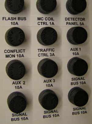
17 UPS & Bypass Breakers ( UPS Ready option, if equipped) Supplementary Fusing 17

18 4.3. To Turn Off an Individual Circuit Determine the correct fuse or circuit breaker that is in the circuit. Remove the fuse from the circuit s fuse holder or switch the circuit breaker to the off position Generator Mode / Connecting a Generator (Generator option only) Breaker Feeds Put PDA into Generator Mode: A generator may be connected to the PDA by plugging in a generator to the 120VAC, 20A male twist-lock plug at the end of the generator connection dongle. Throw the generator transfer switch to Gen once the generator is connected and operating properly. The PDA is now being fed from the generator and the AC service or Util is not connected. Return PDA to AC Service: Throw the generator transfer switch from Gen to Util. The PDA is now being fed from the AC Service. 18
19 (OPTIONAL) TO LOADS (OPTIONAL) (OPTIONAL) Generator Transfer Switch Details 4.5. Place PDA in Bypass, Disable or Auto Mode ( UPS Ready option only) Force Manual Bypass: Move the Bypass Control Switch from Auto or Disable to Bypass to force the bypass to manually bypass the UPS circuit and continue to power the load if AC service is present. The UPS can be removed for maintenance. The red indicator on the front panel will light representing that the circuit is in bypass mode. Select Auto Sensing of a UPS: Move the Bypass Control Switch from Bypass to Auto to allow the bypass to switch to UPS power if it senses a UPS present. If a UPS is not present and operating, the bypass will operate in bypass mode automatically and a red indicator will be lit. Forcing the Bypass to operate in UPS Mode: Move the Bypass Control Switch from Auto or Bypass to Disable to force the bypass to operate off of the UPS. In this mode, the bypass system will not automatically bypass the UPS if the UPS is not present or is turned off. 19

20 Bypass Circuit Details (Optional) 20
21 5. Maintenance The PDA is intended for installation in a temperature and humidity controlled environment, free of conductive contaminants with unrestricted airflow. Absolute maximum ambient temperature at sea level must not exceed 74ºC (165ºF). Maintenance and servicing of the PDA requires access to the front and side of the PDA. Provide the necessary free space to access the side panel of the PDA Reset a Breaker If a circuit has tripped, first find the cause of the problem. After the problem is fixed, find the breaker that looks out of the on position or is in the off position. Place that breaker back into the on position to reset. Please note that the main service breaker needs to be pushed to the off position and then into the on position to be reset Fuse Replacement If a circuit is not working and has caused a fuse to clear or blow, first find the cause of the problem. After the problem is fixed, find the fuse that blew. Remove that fuse from its holder by pushing in and twisting counterclockwise. The fuse can now be removed and will not be disconnected from the live circuit. Replace fuse with same rating and type and replace by conducting the reverse of the above process. WARNING: REPLACE FUSE WITH SAME TYPE AND RATING. 21


22 Replacing a Fuse 5.3. Air Gap Lightning Arrestor Inspections & Replacement Inspect for burns, open wire leads, cracks or any other damage. For replacement, remove damaged arrestor and terminate new air gap arrestor to terminals 1, 2 and 5 as shown in the figure. WARNING: ONLY REPLACE SURGE SUPPRESSOR MODULE WITH FACTORY APPROVED MODULES. WARNING: ONLY QUALIFIED PERSONNEL SHOULD CONDUCT MAINTENANCE ON THE PDA. 22


23 6. Optional Extras 6.1. UPS (For UPS Ready PDA) A UPS may be connected to the PDA with the supplied connections. A cable is available from your PDA dealer and will be ordered depending on the types of terminations the UPS has. Please consult the manufacturer for ordering the cable with the required types of terminations Battery Connection The battery connection is made at the bottom of the PDA using a simple 6-pole snap-on battery connector. The corresponding cable and batteries can be obtained from your PDA dealer UPS Connection The UPS connection is made at the top rear of the PDA. This connection is an 8- pole snap-on cable and can be obtained from your PDA dealer. 23
24 7. Technical Data VOLTAGE PHASES/POLES CURRENT RATING OTHER Utility (AC) Service 120VAC 1 Phase 30A - Main Breaker 120VAC 1 Pole 30A Generator Connection 120VAC 1 Phase 20A Generator Transfer Switch 120VAC DPDT 30A Automatic Maintenance Bypass 120VAC - 15A 10kA Interrupt (22kA optional) 10kA Interrupt (22kA optional) 10kA Interrupt (22kA optional) 10kA Interrupt (22kA optional) UPS AC Connection 120VAC 1 Phase 15A - UPS DC & Battery Connection 72VDC MAX Watts Max Temperature Rating -40 C to +74 C, Non-Condensing, Sea Level 24
25 8. Contact Information 8.1. Additional Purchases or Upgrades Always On UPS Systems Inc. Bldg Campion Road, Kelowna, BC, Canada, V1X 7S8 Phone: (250) Ext 451 Fax: (250) sales@alwayson.com Website: QA / Warranty Questions Always On UPS Systems Inc. Bldg Campion Road, Kelowna, BC, Canada, V1X 7S8 Phone: (250) Ext 209 Fax: (250) qa@alwayson.com Website: Software Questions Always On UPS Systems Inc. Bldg Campion Road, Kelowna, BC, Canada, V1X 7S8 Phone: (250) Ext 204 Fax: (250) webmaster@alwayson.com Website: 25
GES-102NDM GES-152NDM GES-102NSM
 UPS Status Module For Traffic Applications With GES-102NDM GES-152NDM GES-102NSM Operators Manual Version 1.1 THIS PAGE IS INTENTIONALLY BLANK Note The instructions contained in this manual are not intended
Always "On" UPS Systems Inc. USER MANUAL
 Always "On" UPS Systems Inc. SMART HOME PROTECTOR USER MANUAL Bldg 1-150 Campion Road, Kelowna, BC, Canada, V1X 7S8 Phone: (250) 491-9777 Ext. 451, Fax: (250) 491-9775, Email: sales@alwaysonups.com Web
Model 2460-KIT. Screw Terminal Connector Kit. Description / September 2014 *P * 1
 Keithley Instruments 28775 Aurora Road Cleveland, Ohio 44139 1-800-935-5595 http://www.keithley.com Model 2460-KIT Screw Terminal Connector Kit Description The Model 2460-KIT Screw Terminal Connector Kit
S Reclosers Form 4C Microprocessor-Based Recloser Control KME (120V) and KME (240V) Analog Current Metering Accessory Design II
 and KME (240V) Analog Current Metering Accessory Design II") Reclosers Form 4C Microprocessor-Based Recloser Control KME4-88-1 (120V) and KME4-88-2 (240V) Analog Current Metering Accessory Design II Service Information S280-77-6 961015, 961016 Figure 1. Kyle KME4-88
Reclosers Form 4C Microprocessor-Based Recloser Control KME4-88-1 (120V) and KME4-88-2 (240V) Analog Current Metering Accessory Design II Service Information S280-77-6 961015, 961016 Figure 1. Kyle KME4-88
Model 8020-KHV. Kelvin Keithley Triaxial Connector Card. Description / October 2014 *P * 1
 Keithley Instruments 28775 Aurora Road Cleveland, Ohio 44139 1-800-935-5595 http://www.keithley.com Model 8020-KHV Kelvin Keithley Triaxial Connector Card Description The Model 8020-KHV Keithley HV Connector
This 4200-RM Rack Mount Kit is for installation in 4200-CAB series cabinets only.
 Keithley Instruments, Inc. 28775 Aurora Road Cleveland, Ohio 44139 (440) 248-0400 Fax: (440) 248-6168 www.keithley.com Model 4200-RM Rack Mount Kit Packing List Introduction NOTE This 4200-RM Rack Mount
Model 8020-STC. Kelvin Standard Triaxial Connector Card. Description / October 2014 *P * 1
 Keithley Instruments 28775 Aurora Road Cleveland, Ohio 44139 1-800-935-5595 http://www.keithley.com Model 8020-STC Kelvin Standard Triaxial Connector Card Description The Model 8020-STC Kelvin Standard
Obtaining Documentation and Submitting a Service Request, page xvii Safety Warnings, page xvii Safety Guidelines, page xx
 Preface Obtaining Documentation and Submitting a Service Request, page xvii Safety s, page xvii Safety Guidelines, page xx Obtaining Documentation and Submitting a Service Request For information on obtaining
Configurable Output Distribution. 120V / 208V / 240V 60Hz. User Manual English
 Configurable Output Distribution 120V / 208V / 240V 60Hz User Manual English TABLE OF CONTENTS IMPORTANT SAFETY INSTRUCTIONS.......................... 1 GLOSSARY OF SYMBOLS....................................
Installation and Operation Guide for PD5200 and PD5300 Automatic Transfer Switch
 Installation and Operation Guide for PD5200 and PD5300 Automatic Transfer Switch PD52 PD52S & PD52DCS PD53-100 te: The PD52S & PD52DCS are provided with LED lights. The GREEN LIGHTS indicate Shore Power
SAVE THESE INSTRUCTIONS
 READ AND FOLLOW ALL SAFETY INSTRUCTIONS! SAVE THESE INSTRUCTIONS AND DELIVER TO OWNER AFTER INSTALLATION IMPORTANT SAFEGUARDS! When using electrical equipment, basic safety precautions should always be
POWER AVAILABILITY 2U POD USER MANUAL. Power Output Distribution 120 Volt
 POWER AVAILABILITY 2U POD USER MANUAL Power Output Distribution 120 Volt TABLE OF CONTENTS IMPORTANT SAFETY INSTRUCTIONS.......................................... 1 GLOSSARY OF SYMBOLS..................................................
Model 7705 Control Module
 www.keithley.com Model 7705 Control Module User s Guide PA-696 Rev. D / October 2006 A G R E A T E R M E A S U R E O F C O N F I D E N C E Safety Precautions The following safety precautions should be
Model 2657A-LIM-3 LO Interconnect Module
 Keithley Instruments, Inc. 28775 Aurora Road Cleveland, Ohio 44139 1-888-KEITHLEY http://www.keithley.com Model 2657A-LIM-3 LO Interconnect Module User's Guide Description The Model 2657A-LIM-3 LO Interconnect
SPECIAL INSTRUCTIONS FOR CAPACITORS COMPACT GENERATORS
 SPECIAL INSTRUCTIONS FOR CAPACITORS COMPACT GENERATORS (WITH CAPACITOR CHARGER BOARD A3517-02) The process depends on Generator and System configuration. This document applies to installation of Capacitors
Installation, Operation and Maintenance Manual
 Document 481200 VGD-100 Vari-Green Drive Installation, Operation and Maintenance Manual Please read and save these instructions for future reference. Read carefully before attempting to assemble, install,
Model 2600B-PM V Protection Module with 1 A Clamp. Description / April 2015 *PPA * 1
 Keithley Instruments 28775 Aurora Road Cleveland, Ohio 44139 1-800-935-5595 http://www.keithley.com Model 2600B-PM-1 200 V Protection Module with 1 A Clamp Description The Model 2600B-PM-1 200 V Protection
Owner s Manual. Isolate. Restore. Inspire! Power Conditioners Audio / Video Power Isolation Units Rack Mount / Consumer Series
 Owner s Manual 19 Pro Series Rack Mount (RK) Faceplate Isolate. 17 Consumer Series (C) Faceplate Available in Black (B) and Silver (S) Colours Restore. Power Conditioners Audio / Video Power Isolation
INSTALLATION INSTRUCTIONS
 TM REPLACEMENT PARTS FOR USE WITH CX SERIES PANELS INSTALLATION INSTRUCTIONS Hubbell Control Solutions 9601 Dessau Road Building One Suite 100 Austin, TX 78754 Toll Free: 888-698-3242 Fax: 512-450-1215
DANGER DANGER: is used in this manual to warn of high voltages capable of causing shock, burns, or death.
 Installation/Operation Manual TABLE OF CONTENTS Page UNPACKING AND INSTALLATION Unpacking and Preliminary Inspection...2, 3 Model Number...9 LOCATION CONSIDERATIONS Environment, Equipment Performance,
Line Interactive 1000VA/1400VA/2000VA Uninterruptible Power System
 USER MANUAL Line Interactive 1000VA/1400VA/2000VA Uninterruptible Power System 614-06762-00 IMPORTANT SAFETY INSTRUCTIONS SAVE THESE INSTRUCTIONS This manual contains important instructions for Line Interactive
Liebert MicroPOD 230V
 AC Power For Business-Critical Continuity Liebert MicroPOD 230V User Manual TABLE OF CONTENTS 1.0 IMPORTANT SAFETY INSTRUCTIONS...........................................1 2.0 GLOSSARY OF SYMBOLS..................................................2
CVU-3K-KIT. 3 kv Bias Tee Kit. Description. Parts list / October 2014 *P * 1
 Keithley Instruments 28775 Aurora Road Cleveland, Ohio 44139 1-800-935-5595 http://www.keithley.com CVU-3K-KIT 3 kv Bias Tee Kit Description The CVU-3K-KIT Bias Tee Kit consists of three bias tees for
POWER AVAILABILITY 2U POD USER MANUAL. Power Output Distribution 230 Volt
 POWER AVAILABILITY 2U POD USER MANUAL Power Output Distribution 230 Volt TABLE OF CONTENTS IMPORTANT SAFETY INSTRUCTIONS.......................................... 1 GLOSSARY OF SYMBOLS..................................................
PS8 - II. Professional Power Sequencer. User s Manual
 PS8 - II Professional Power Sequencer User s Manual IMPORTANT SAFETY INSTRUCTIONS READ FIRST This symbol, whenever it appears, alerts you to the presence of uninsulated dangerous voltage inside the enclosure.
OPERATING AND SERVICE MANUAL. Universal Interface Device 47
 OPERATING AND SERVICE MANUAL Universal Interface Device 47 MAGNA-POWER ELECTRONICS, INC. 39 ROYAL ROAD, FLEMINGTON, NJ 08822 May 24, 2012 SAFETY NOTICE Universal Interface Device 47 (UID46) connects
USER MANUAL. Uninterruptible Power Supply Line-interactive VCL Series UPS VA. GE Critical Power
 Critical Power USER MANUAL Uninterruptible Power Supply Line-interactive VCL Series UPS 400 600 800 1000 1500 VA GE Consumer & Industrial SA General Electric Company CH 6595 Riazzino (Locarno) Switzerland
WBS HARDWIRED SERIES 4-60KVA MAINTENANCE BYPASS SWITCH
 WBS HARDWIRED SERIES 4-60KVA MAINTENANCE BYPASS SWITCH Man 440 Issue 7 1 1. INTRODUCTION... 3 2. INSTALLATION... 3 2.1 Connection of the Mains Supply... 3 2.2 Connection of the Input to the UPS... 4 2.3
CVU-200-KIT. 200 V Bias Tee Kit. Description. Parts list / October 2014 *P A* 1
 Keithley Instruments 28775 Aurora Road Cleveland, Ohio 44139 1-800-935-5595 http://www.keithley.com CVU-200-KIT 200 V Bias Tee Kit Description The CVU-200-KIT Bias Tee Kit consists of three 2600-RBT-200
The power behind competitiveness. Delta Infrasuite Power Management. Power Distribution Unit. User Manual.
 The power behind competitiveness Delta Infrasuite Power Management Power Distribution Unit User Manual www.deltapowersolutions.com Save This Manual This manual contains important instructions and warnings
MFA-0801 & MFA-1201 D-M-E Smart Series Low Voltage Temperature Control System. User s Manual. D-M-E Company
 MFA-0801 & MFA-1201 D-M-E Smart Series Low Voltage Temperature Control System User s Manual D-M-E Company D-M-E Company MFA-0801 & MFA-1201 Page 1 Copyright D-M-E Company 1995. All rights reserved. D-M-E
OPERATING AND SERVICE MANUAL. Universal Interface Device 47
 OPERATING AND SERVICE MANUAL Universal Interface Device 47 MAGNA-POWER ELECTRONICS, INC. 39 ROYAL ROAD, FLEMINGTON, NJ 08822 May 24, 202 SAFETY NOTICE Universal Interface Device 47 (UID47) connects two
PHASETRONICS. SCR Power Control Specialists. EP1 Series Power Control Single Phase SCR Amps OPERATION & SERVICE MANUAL
 PHASETRONICS Specialists EP1 Series Power Control Single Phase SCR 10-50 Amps OPERATION & SERVICE MANUAL Phasetronics, Inc. P.O. Box 5988 1600 Sunshine Drive Clearwater, FL 33765 (727)573-1900 FAX(727)573-1803
INSTALLATION INSTRUCTIONS STZ-R SERIES (ENGLISH)
") Surge-Trap STZ-R series Surge Protective Device (SPD) Danger Hazard of Electrical Shock, Explosion or Arc Flash Only qualified licensed electricians should install or service SPDs Verify that all power
Surge-Trap STZ-R series Surge Protective Device (SPD) Danger Hazard of Electrical Shock, Explosion or Arc Flash Only qualified licensed electricians should install or service SPDs Verify that all power
XBDM. 1015LV, 1020LV, 1030LV, 1020HV Models USER & INSTALLATION MANUAL BYPASS DISTRIBUTION MODULE
 XBDM 1015LV, 1020LV, 1030LV, 1020HV Models USER & INSTALLATION MANUAL www.xpcc.com 2013 Xtreme Power Conversion Corporation. All rights reserved. Table of Contents IMPORTANT SAFETY INSTRUCTIONS:... 4 INTRODUCTION...
PDS8u POWER DISTRIBUTION SYSTEM USER'S MANUAL
 PDS8u POWER DISTRIBUTION SYSTEM USER'S MANUAL 1 IMPORTANT SAFETY INSTRUCTION READ FIRST This symbol, whenever it appears, alerts you to the presence of uninsulated dangerous voltage inside the enclosure-voltage
M215-Z Safety Information (M LL-IG-ZC)
") M215-Z SAFETY M215-Z Safety Information (M215-60-2LL-IG-ZC) This document contains important instructions to use during installation of the M215-Z Zep Compatible Microinverters. To reduce the risk of electrical
M215-Z SAFETY M215-Z Safety Information (M215-60-2LL-IG-ZC) This document contains important instructions to use during installation of the M215-Z Zep Compatible Microinverters. To reduce the risk of electrical
Model GHz 50 Ohm RF Module
 Keithley Instruments 28775 Aurora Road Cleveland, Ohio 44139 1-800-935-5595 tek.com/keithley Model 7711 2 GHz 50 Ohm RF Module Instructions for use with DAQ6510 Introduction The 7711 plug-in module provides
Models 2601B, 2602B, and 2604B System SourceMeter Instruments Quick Start Guide
 Models 2601B, 2602B, and 2604B System SourceMeter Instruments Quick Start Guide Safety precautions Observe the following safety precautions before using this product and any associated instrumentation.
M250 (M LL) Safety
 Safety") M250 SAFETY M250 (M250-60-2LL) Safety Important Safety Information This document contains important instructions to use during installation of the Enphase M250 Microinverter. To reduce the risk of electrical
M250 SAFETY M250 (M250-60-2LL) Safety Important Safety Information This document contains important instructions to use during installation of the Enphase M250 Microinverter. To reduce the risk of electrical
Westell. Breaker Panel Technical Practice NPDRP1114
 030-000218 REV F 1114-03F June 29, 2017 Westell Breaker Panel Technical Practice NPDRP1114 FEATURES DIN rail panel accepts up to 6 DIN rail devices (one surge and 5 breakers) Specific configuration of
Model 2380 Rack-Mount Kit
 Keithley Instruments 28775 Aurora Road Cleveland, Ohio 44139 1-800-935-5595 http://www.tek.com/keithley Model 2380 Rack-Mount Kit Installation Instructions Introduction The Model 2380 Fixed Rack-Mount
Wise HP33 THREE PHASE HIGH PRECISION AVR SURVO-MOTOR AUTOMATIC VOLTAGE STABILIZER
 Wise HP33 THREE PHASE HIGH PRECISION AVR SURVO-MOTOR AUTOMATIC VOLTAGE STABILIZER LEN.MAN.STA.111 Rev.4.00/2010 CONTENTS 1. SAFETY INSTRUCTIONS 1 2. INTRODUCTION 2 3. FRONT PANEL AND CONNECTION BOARD 3
Quick Start Guide TS A
 Quick Start Guide TS 930 125-630A DANGER HAZARD OF ELECTRICAL SHOCK, EXPLOSION, OR ARC FLASH Read and understand this quick start guide before installing and operating the transfer switch The installer
Emerson Network Power provides customers with technical support. Users may contact the nearest Emerson local sales office or service center.
 Liebert PSA iton User Manual Version: V2.8 Revision date: November 14, 2005 Emerson Network Power provides customers with technical support. Users may contact the nearest Emerson local sales office or
Wa r n i n g-wa r n i n g-wa r n i n g
 Installation Instructions of the Power Analyzer Wa r n i n g-wa r n i n g-wa r n i n g Read and understand this manual before connecting device. Death, fire or serious injury can occur from using equipment
TOT Series Manual. North American CE and UK Models. CE Models. UK Models. North American Models
 TOT Series Manual North American CE and UK Models CE Models UK Models North American Models Table of Content 1. Important Safety Instructions 2. Description Shipping Carton & Packing Material Placement
Explosion-Protected Arc-Fault Protection ExAFCI Arc-Fault Circuit Interrupter
 Installation, Operation & Maintenance Sheet Explosion-Protected Arc-Fault Protection ExAFCI Arc-Fault Circuit Interrupter > Contents 1 Contents 1 Contents...2 2 General Information...2 2.1 Manufacturer...2
The PST-6. Owners Manual 1
 The PST-6 Owners Manual 1 Introduction Thank you for purchasing the Furman Power Station-6 Power Conditioner. For over 30 years, Furman has pioneered the development of AC power products for the most demanding
BS 287 DUAL CHANNEL POWER SUPPLY. User Manual. January 2017 V1.0
 BS 287 DUAL CHANNEL POWER SUPPLY User Manual January 2017 V1.0 Table of contents 1.0 SAFETY INSTRUCTIONS... 3 2.0 GENERAL DESCRIPTION PS 289... 4 3.0 MECHANICAL INSTALLATION... 5 4.0 MAINS POWER & SAFETY
Click Desktop Kit. Click Desktop Kit
 Click Desktop Kit Click Desktop Kit The Click Desktop Kit is a desktop-mounted set that gives you the building blocks necessary to work with your Click modules at your computer, whether you re testing
GE Digital Energy. Power Quality
 GE Digital Energy Power Quality INSTALLATION, OPERATION AND MAINTENANCE MANUAL GE TRANQUELL Enhanced Thermal Protection (ETP) Series Wall Mounted Medium and High Exposure Surge Protective Devices (SPDs)
3190 Series Touch Screen POS Workstation
 3190 Series Touch Screen POS Workstation INSTALLATION GUIDE Congratulations on your purchase of UTC RETAIL s innovative 3190 Series Touch Screen POS Workstation. The 3190 Series is designed for use in
M215 (M215-60) Safety
 Safety") M215 QUICK INSTALL GUIDE M215 (M215-60) Safety Important Safety Information This document contains important instructions to use during installation and maintenance of the Enphase M215 Microinverter. To
M215 QUICK INSTALL GUIDE M215 (M215-60) Safety Important Safety Information This document contains important instructions to use during installation and maintenance of the Enphase M215 Microinverter. To
MFP5G, MFP8G, & MFP12G D-M-E Smart Series Mainframes
 MFP5G, MFP8G, & MFP12G D-M-E Smart Series Mainframes User s Manual D-M-E Company D-M-E Company MFP5G, MFP8G, MFP12G Page 1 Copyright D-M-E Company 1999. All rights reserved. D-M-E Company products are
RE-82 RACK MOUNT DIMMER OWNERS MANUAL. 8 X 2400Watts. Revision /29/2007
 RE-82 RACK MOUNT DIMMER 8 X 2400Watts OWNERS MANUAL Revision 2.4 11/29/2007 Page 2 of 8 RE-82 CONTROL PANEL DESCRIPTION The RE-82 is an 8 channel dimmer with a maximum capacity of 2,400 watts per channel
DOT MATRIX PRINTER SP6000 SERIES
 DOT MATRIX PRINTER SP6000 SERIES Hardware Manual < Approval: CEL > Trademark acknowledgments SP6000 : Star Micronics Co., Ltd. Notice All rights reserved. Reproduction of any part of this manual in any
SECTION TRANSIENT VOLTAGE SUPPRESSION FOR LOW-VOLTAGE ELECTRICAL POWER CIRCUITS
 SECTION 264313 - TRANSIENT VOLTAGE SUPPRESSION FOR LOW-VOLTAGE ELECTRICAL POWER CIRCUITS PART 1 - GENERAL 1.1 RELATED DOCUMENTS A. Drawings and general provisions of the Contract, including General and
PowerMust Office Uninterruptible Power System
 USER MANUAL E PowerMust Office Uninterruptible Power System 614-05737-05 28-2PRO000001 IMPORTANT SAFETY INSTRUCTIONS SAVE THESE INSTRUCTIONS This manual contains important instructions for Models PowerMust
D-Pack 6 Classic ORDERCODE 50315
 D-Pack 6 Classic ORDERCODE 50315 Congratulations! You have bought a great, innovative product from Showtec. The Showtec D-Pack 6 Classic brings excitement to any venue. Whether you want simple plug-&-play
Breaker Panel Technical Practice NPDRP1114
 030-000218 REV E 1114-03E January 30, 2013 Westell Breaker Panel Technical Practice NPDRP1114 FEATURES DIN rail panel accepts up to 6 DIN rail devices (one surge and 5 breakers) Specific configuration
BS 181 SINGLE CHANNEL POWER SUPPLY USER MANUAL
 BS 181 SINGLE CHANNEL POWER SUPPLY USER MANUAL Issue 2011 ASL Intercom BV DESIGNED & MANUFACTURED BY: ASL Intercom B.V. Zonnebaan 42 3542 EG Utrecht The Netherlands Tel: +31 (0)30 2411901 Fax: +31 (0)30
User s Guide. POWERVAR Single Phase Power Conditioners
 POWERVAR Single Phase Power Conditioners User s Guide Industrial Conditioners GPI Series B Conditioners GPI Series 1 Conditioners 2-15 kva Single Phase Conditioners GPI Series 1 Conditioners RoHS Compliant
Model 2380 Rack-Mount Kit
 Keithley Instruments 28775 Aurora Road Cleveland, Ohio 44139 1-800-935-5595 http://www.tek.com/keithley Model 2380 Rack-Mount Kit Installation Instructions Introduction The Model 2380 Fixed Rack-Mount
3-Phase, Dual-Input 6-Slot Power Supply System STARTUP GUIDE
 3-Phase, Dual-Input 6-Slot Power Supply System STARTUP GUIDE -ST-01 Page 1 of 10 November 2016 2016 Copyright Lite-On Technology Corporation ALL RIGHTS RESERVED. Lite-On is a trademark of Lite-On Technology
VFI RTG PDU 6-10K. Installation and user manual. Service and support: Call your local service representative
 VFI RTG PDU 6-10K Installation and user manual Service and support: Call your local service representative SAFETY INSTRUCTIONS SAVE THESE INSTRUCTIONS. This manual contains important instructions that
TOT Series Manual. North American and International Models - without optional faceplate. Receptacle Panel of International Models, CE model shown
 TOT Series Manual North American and International Models - without optional faceplate Receptacle Panel of International Models, CE model shown North American Models Table of Content 1. Important Safety
SAVE THESE INSTRUCTIONS
 OUTDOOR HARDWIRE INSTALLATION INSTRUCTIONS Please read and save these instructions. Read carefully before using product. Protect yourself and others by observing all safety information, warnings and cautions.
HV-CS kv Edge Mount Triaxial Jack
 Keithley Instruments 28775 Aurora Road Cleveland, Ohio 44139 1-800-935-5595 http://www.tek.com/keithley HV-CS-1589 3 kv Edge Mount Triaxial Jack Installation Information Description The Keithley Instruments
What s in the Box. Table of Contents
 Table of Contents 1. What s in the Box 2. Warning 2. Overview 3. Quick Start Guide 4. Rear Panel 5. Front Panel 5. DC trigger 5. Logo trim tool 6. Troubleshooting Guide 7. Warranty and Service 8. Contact
Specifications, Installation, and Operating Instructions
 Specifications, Installation, and Operating Instructions Model: Power Vantage AC Panel Protector CAUTION: The installation of a surge protection device () must be done by qualified electrical personnel.
LINE VOLTAGE TESTER CT101 USER S MANUAL. Please read this manual carefully and thoroughly before using this product.
 LINE VOLTAGE TESTER USER S MANUAL CT101 Please read this manual carefully and thoroughly before using this product. KEY FEATURES Visual indication of AC or DC voltage Easy to use approved Safe for CAT
Overview These instructions are presented as a guideline for installing and setting up the LX Series Breaker Control Panel.
 LX Breaker Control Panels Installation and Setup Procedure Hubbell Building Automation, Inc. 9601 Dessau Road Building One Suite 100 Austin, Texas 78754 512-450-1100 512-450-1215 Fax www.hubbell-automation.com
Service Instructions. Conductor 420
 Service Instructions Conductor 420 Listed, File No. E195547 Input: 480 VAC, 50/60 HZ. (Operating range 380-480 VAC) 20 AMP MAX OUTPUT W/25 AMP FUSE Output: 0-90% of Input Voltage Table of Contents General
2260B-RMK-Series Rack Mount Kit
 Keithley Instruments, Inc. 28775 Aurora Road Cleveland, Ohio 44139 1-888-KEITHLEY http://www.keithley.com Assembly and Mounting Instructions Introduction The 2260B-RMK-Series Rack Mount Kit is suited for
ipad Charge & Sync Cart Model MCC2 ipad Cart 430-MCC2-User Manual-010 Is a Registered Trademark of Apple Inc. ipad
 ipad Charge & Sync Cart Model MCC2 ipad Cart ipad Is a Registered Trademark of Apple Inc. 430-MCC2-User Manual-010 1. ipad Cart Specifications MCC2 Mobile Charge & Sync Cart Extra Drawer Reserved space
Torque Series LCD Remote Panel Installation/Operation Manual Model: TQ-DSP-12/24
 Torque Series LCD Remote Panel Installation/Operation Manual Model: TQ-DSP-12/24 Section Page Introduction 1 Materials Provided 1 I) Safety Instructions 1 A) Inverter Safety Instructions 1 B) Battery Safety
Thank you for selecting UTC RETAIL s innovative Model 1170 Point of Sale solution!
 1170 POS SYSTEM 1170 INSTALLATION GUIDE Thank you for selecting UTC RETAIL s innovative Model 1170 Point of Sale solution! This Installation Guide will help you efficiently install the 1170 POS. The document
4170 POS System Installation Guide
 4170 POS System 4170 Installation Guide Thank you for selecting UTC RETAIL s innovative Model 4170 Point of Sale solution! This Installation Guide will help you efficiently install the 4170 POS. The document
M215 Safety (M LL-S22-IG / S23-IG / S24-IG)
") M215 SAFETY M215 Safety (M215-60-2LL-S22-IG / S23-IG / S24-IG) Important Safety Information This document contains important instructions to use during installation of the Enphase M215 Microinverter. To
M215 SAFETY M215 Safety (M215-60-2LL-S22-IG / S23-IG / S24-IG) Important Safety Information This document contains important instructions to use during installation of the Enphase M215 Microinverter. To
User Guide CPSMP VAC Power Supply Module: PointSystem CPSMC Accessory CPSMC Accessory. Contents.
 User Guide CPSMP-205 110 240 VAC Power Supply Module: PointSystem CPSMC1800-200 Accessory CPSMC1900-100 Accessory Contents Contents...1 Description...1 Cautions and Warnings...2 Definitions...2 Power supply
H Series PLC. ! : Indicates Compulsion. EH-150 Analog input module EH-AXH8M Instruction manual. Safety precautions DANGER CAUTION COMPULSION
 H Series PLC EH-150 Analog input module EH-AXH8M Instruction manual Thank you for purchasing a Hitachi Programmable Logic Controller. To operate it safely, please read this instruction manual and all the
Installation and Operation Back-UPS BR1000G-IN / BR1500G-IN
 Installation and Operation Back-UPS BR1000G-IN / BR1500G-IN Important Safety Information Read the instructions carefully to become familiar with the equipment before trying to install, operate, service
Installation Instructions
 50ES, 50EZ, 50GL, 50GS, 50GX, 50JS, 50JX, 50JZ, 50SD, 50SZ, 50VL, 50VT, 50XP, 50XZ 601A, 602A, 602B, 604A, 604B, 604D, 607C, 701A, 702A, 702B, 704A, 704B, 704D, 707C PA1P, PA2P, PA3P, PH1P, PH2P, PH3P
EOS-6000 Series Optical A/B Switch User Manual DC Version
 EOS-6000 Series Optical A/B Switch User Manual DC Version For more information on this and other products: Contact Sales at EMCORE 626-293-3400, or visit www.emcore.com. Table of Contents Table of Contents...2
Omnitron Systems Technology, Inc. 1. iconverter. 19-Module Managed Power Chassis User s Manual
 Omnitron Systems Technology, Inc. 1 iconverter 19-Module Managed Power Chassis User s Manual 27 Mauchly, #201, Irvine, CA 92618 Phone: (949) 250-6510; Fax: (949) 250-6514 2 Omnitron Systems Technology,
Tempco Instruction Manual
 Tempco Instruction Manual 1/16 DIN Solid State Temperature Controller Relay Output Solid State Output For Heating Model Numbers: TEC-901, TEC-902, TEC-905 Temperature controls in this series are designed
Zonit μats TM Users Guide μats1-lv Version 1.2
 Zonit μats TM Users Guide μats1-lv Version 1.2 Table of Contents Product Overview...2 Pre-Installation Considerations...2 Product Features...3 Installation...4 Optional Accessories...4 μats TM Operational
EC Series. Safety Guide
 EC Series Safety Guide R5906018/02 01/07/2017 Barco Inc, Image Processing 3078 Prospect Park Drive, Rancho Cordova, CA, 95670, USA Phone: +1 916 859-2500 Fax: +1 916 859-2515 Support: www.barco.com/en/support
TRC-190 User s Manual
 User s Manual Edition 3.2, May 2017 www.moxa.com/product 2017 Moxa Inc. All rights reserved. User s Manual The software described in this manual is furnished under a license agreement and may be used only
SURGE PROTECTION USER MANUAL. Surge Protection Device PORTABLE POWER DISTRIBUTION SURGE PROTECTION DEVICE (SPD) B
 B") SURGE PROTECTION PORTABLE POWER DISTRIBUTION SURGE PROTECTION DEVICE (SPD) USER MANUAL Surge Protection Device B 01 156 9000 This Surge Protection Device is intended for professional use only Read this
SURGE PROTECTION PORTABLE POWER DISTRIBUTION SURGE PROTECTION DEVICE (SPD) USER MANUAL Surge Protection Device B 01 156 9000 This Surge Protection Device is intended for professional use only Read this
Operating instructions AS-i SmartLine module AC3200 AC /00 06/2016
 Operating instructions AS-i SmartLine module AC3200 AC3201 80237876/00 06/2016 Contents 1 Preliminary note...3 1.1 Symbols used...3 1.2 Warnings used...3 2 Safety instructions...3 2.1 General...3 2.2 Target
NSI DIGITAL DIMMING SYSTEM DDS 5300 / 5600 DIMMER PACK
 INTRODUCTION NSI DIGITAL DIMMING SYSTEM INSTALLATION AND OPERATION GUIDE The NSI DDS 5300 and DDS 5600 dimmers represent a key part of a state of the art, integrated lighting control system. These dimmers
OPERATING AND SERVICE MANUAL. Universal Interface Device 45
 OPERATING AND SERVICE MANUAL Universal Interface Device 45 MAGNA-POWER ELECTRONICS, INC. 81 FULTON STREET, BOONTON, NJ 07005 September 7, 2005 SAFETY NOTICE Universal Interface Device 45 (UID45) connects
HITACHI. EH-150 series PLC EH-RTD8 Resistance Temperature Detective input module Instruction manual. Safety precautions
 HITACHI EH-150 series PLC Resistance Temperature Detective input module Instruction manual Thank you for purchasing a Hitachi Programmable Logic Controller. To operate it safely, please read this instruction
2016 SIGLENT TECHNOLOGIES CO.,LTD
 Quick Strat SDM3045X Digital Multimeter QS06034-E01A 2016 SIGLENT TECHNOLOGIES CO.,LTD Copyright Information SIGLENT TECHNOLOGIES CO., LTD. All rights reserved. The information provided in this manual
Cantata m100 Amplifier
 Cantata m100 Amplifier Getting Started Guide www.resolutionaudio.com +1.415.553.4100 Safety Information CAUTION RISK OF ELECTRICAL SHOCK DO NOT OPEN CAUTION: TO REDUCE THE RISK OF ELECTRICAL SHOCK, DO
IO-AO6X I/O Expansion Module 6 Isolated Analog Outputs
 IO-AO6X I/O Expansion Module 6 Isolated Analog Outputs The IO-AO6X is an I/O Expansion Module that can be used in conjunction with specific Unitronics OPLC controllers. The module offers 6 12-bit isolated
HP R/T2200 UPS. Overview. Precautions. Installation Instructions. The HP UPS R/T2200 features power protection for loads up to 2200 VA/1600 W.
 HP R/T2200 UPS Installation Instructions Overview The HP UPS R/T2200 features power protection for loads up to 2200 VA/1600 W. For more information about any of the topics covered in this document, see
Table of Contents. Safety. Attention. Warnings
 Solstart Miniature Soft Starter 8-58A, 220-600V Instruction Manual Ver. 21.2. 2002 Table of Contents Page Subject 3 Starter Selection 4 Installation Notes 5 Wiring 6 Starter Settings & Start-up Procedure