Copper USER MANUAL.
|
|
|
- Shanon Hodge
- 5 years ago
- Views:
Transcription

1 Copper USER MANUAL
2 ENGLISH TABLE OF CONTENTS 1 Introduction About product Safety precautions Intended use About this document Before you start Scope of delivery System requirements WireXpert PC Software and Firmware Install software Upgrade firmware Understanding WireXpert WireXpert Overview Dual Control System (DCS) WireXpert Adapters Cabling Certification and Testing Memory Battery Information Power Supply Dimension Environmental Conditions WireXpert User Interface Touch Screen Layout The One Touch Access Button Setting Reference Configuring an AUTOTEST Setting up WireXpert Testing Guide for Permanent Link Testing Testing Guide for Channel Testing
3 7 Performing an AUTOTEST Understanding AUTOTEST NEXT and RL Fault Locating Managing test result(s) Exporting test results into export PC Software Declarations Appendix Technical Support

4 1 Introduction 1.1 About product Softing s WireXpert, with its unparalleled 2,500 MHz measurement range, is the first cable certifier with capability to certify the highest performance cabling systems in enterprise networks and data centers. Cable installers make significant gain in productivity with WireXpert s industry leading test speed and ease of use. With certification testing up to Class FA and CAT8 copper cabling, as well as MPO, SM, MM and MMEF fiber optic cabling, WireXpert is ready for 40G and beyond. 1.2 Safety precautions Read this manual before starting For damages due to improper connection, implementation or operation Softing refuses any liability according to our existing warranty obligations. Note This symbol is used to call attention to notable information that should be followed during installation, use, or servicing of this device. Hint This symbol is used when providing you with helpful user hints. CAUTION Selection of option may cause all or partial of saved data and/or settings in the device to be erased or restored to non-reversible original factory state. Backing up of saved result(s) is recommended before executing option. 4
5 CAUTION CAUTION indicates a potentially hazardous situation which, if not avoided, may result in minor or moderate injury. WARNING WARNING indicates a potentially hazardous situation which, if not avoided, could result in death or serious injury DANGER DANGER indicates an imminently hazardous situation which, if not avoided, will result in death or serious injury. This signal word is to be limited to the most extreme situations. 1.3 Intended use WireXpert series has been designed for use in factory, process and building control. The unit must not be used in explosion hazard areas. The permissible ambient conditions given in the Technical Data must be complied with. The faultless and safe operation of the product requires proper transport, proper storage and installation, and expert operation and maintenance in accordance with the manual. 1.4 About this document Read this manual before starting For damages due to improper connection, implementation or operation Softing refuses any liability according to our existing warranty obligations Document history Document version Modifications compared to previous version 105 Firmware update to v7.3. Table 1: Document history 5
6 1.4.2 Conventions used The following conventions are used throughout Softing customer documentation: Keys, buttons, menu items, commands and other elements involving user interaction are set in bold font and menu sequences are separated by an arrow Open Start Control Panel Programs Buttons from the user interface are enclosed in brackets and set to bold typeface Press [Start] to start the application Coding samples, file extracts and screen output is set in Courier font type MaxDlsapAddressSupported=23 Filenames and directories are written in italic Device description files are located in C:\<product name>\delivery\software\ Device Description files 1.5 Before you start Check that the latest export PC software and firmware is installed in the workstation and WireXpert respectively to ensure the latest features are available. Ensure WireXpert is calibrated annually for optimum accuracy. Key differences between WX4500 and WX500 Features WX4500-FA WX500 Frequency of measurement 2500 MHz 500 MHz Accuracy Specification Level 2G Level IIIe Fiber Testing option Yes No Class FA/CAT 8 options Yes No Patch Cord Test adapters Yes Yes 6

 WireXpert WX4500 or WireXpert")

 Talk-set headphones")
 CAT 6A Channel adapters")
 Straps 1.")

7 1.6 Scope of delivery WireXpert WX-4500-FA or WX-500-FA comprises the following parts: Soft or Hard carrier case (WX_AC_SOFTCASE) or (WX_AC_HARDCASE) WireXpert WX4500 or WireXpert WX500 (LOCAL and REMOTE) Calibration Certificate & USB Flash Drive Power Adapters - Input: VAC/0.8A Output: 12VDC/3.0A (WX_AC_PWRAD) Talk-set headphones (WX_AC_TALKSET1) LCD Protective Cover (WX_LCD_COVER) CAT 6A Channel adapters (WX_AD_6ACH2) Permanent Link adapters & cords (WX_AD_6ALKIT2) Straps 1.7 System requirements Hardware PC Operating system Windows Vista, 7, 8.x or 10 (32 bit or 64 bit) Intel Core i3, 2.4Ghz and above 4 GB of RAM 200 MB of free space of installation Microsoft.NET framework 4.0 7
8 2 WireXpert PC Software and Firmware 2.1 Install software 1 Download the latest export PC software from 2 If this is a new installation, install the files in the package in the following order a. Step_1_drvupdate-amd64.exeb b. Step_2_dotNetFx40_Full_x86_x64.exed c. Step_3_vcredist_x64.exe d. Step_4_vcredist_x64_mfc.EXE e. Step_5_eXport_setup_v7.2.0_x64.exe 3 If this is an upgrade from an earlier version from 6.x and above, install only item e. User Manuals For more information on installation and using export PC software, please refer to Installation Guide for export PC software and User Manual for export PC software. Note Softing IT Networks has ceased support for ReportXpert v5.x and earlier. Please contact asia-support.itnetworks@softing.com for more information. 2.2 Upgrade firmware 1 Download and install the latest export PC software. 2 Connect an USB flash drive to the workstation. 3 Run export PC software. 4 Go to Tools Update Device Firmware 5 Click [OK] and select USB drive from Export to USB window. 6 Click [Export] and [OK] to proceed. 8
9 7 Please wait while exporting takes place. This process may take a while. 8 Remove USB flash drive from workstation and connect to WireXpert. 9 Select [Upgrade Firmware] from prompt and click [OK] button to continue. 10 If prompt did not appear, check that USB icon is present on the status bar, and press the [SETUP] button Settings 2 Storage USB. 11 Please wait while upgrading takes place. This process may take a while. 12 Upgrade process is complete. CAUTION Saved test results and settings may be erased during upgrading. You are recommended to save all test results before upgrading the firmware. 9
")

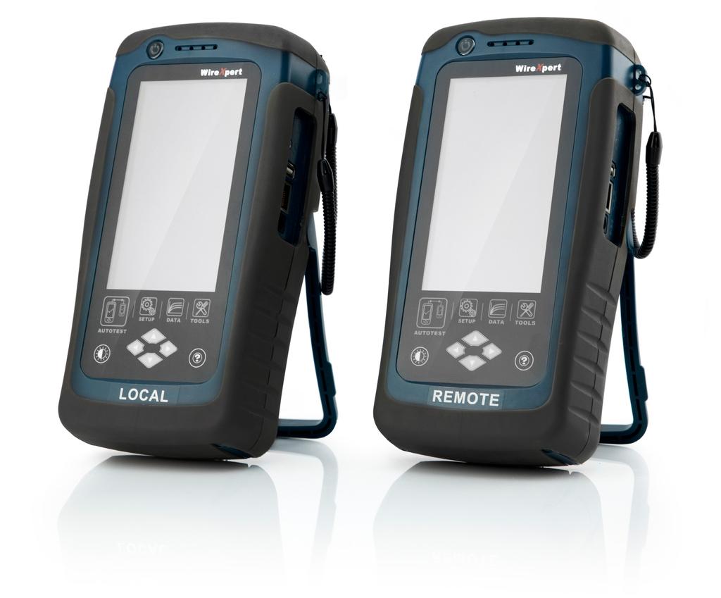
10 3 Understanding WireXpert 3.1 WireXpert Overview Power ON/OFF button Touch sensitive color LCD screen USB device port Audio port USB host connector for flash drive RJ-45 Ethernet port for remote control Power supply port (12V) One-Touch access buttons Brightness control button Navigation scroll buttons Context sensitive Help button Probe interface connector Battery compartment Part Power ON/OFF Button Touch Sensitive LCD screen USB device port Audio port USB Host port RJ-45 Ethernet port Power Supply port One-touch access buttons Brightness Control Navigation scroll buttons Functionality To turn on the device, press the power button for 5 seconds. To turn off the device, press the power button, and select OK on the power off dialog box. Alternately, press and hold the power button for 10 seconds (not recommended). The LED in the power button turns green if the unit is turned on. The LED on the power button turns red when the device is charging in stand-by mode, orange if it s turned on. Performs test executions and viewing of results. Enables remote connection to the PC for remote control update and exporting saved results. Enables vocal communication between LOCAL and REMOTE units when connected to talk set headphones (WX_AC_TALKSET). Enables results to be exported and firmware upgrade via USB flash drive. Enables loading of custom limits and labels for list based testing. Enables communication between two sets of WireXpert for Alien Crosstalk testing Performs charging of device when connected to power adapter shipped with WireXpert. (WX_AC_PWRAD) Main functional buttons AUTOTEST, SETUP, DATA and TOOLS for WireXpert. Enables quick AUTOTEST and results viewing in a single click. Adjusts the brightness level of the LCD display. Performs navigation in long lists. 10
11 Part Context sensitive help Probe interface connector Battery compartment Functionality Provides simple explanation relevant to the functionality on the current screen (available in future version). When connected with different probe adapters (e.g. CAT6A channel or Permanent Link), WireXpert will enable specified certification test to be conducted. Battery storage compartment. Unscrew to replace battery (WX_AC_BAT1). 3.2 Dual Control System (DCS) WireXpert consists of two identical devices, LOCAL and REMOTE, for dual-end testing and certification. Both devices utilize easy to use LCD touch-screen technology and graphical user interface. The DCS ensures the same graphical data on the LOCAL units are received on the REMOTE unit real-time, improving efficiency and productivity significantly as test data and settings can be viewed from REMOTE and LOCAL side. In the event of a wire map failure, the DCS will enable the operator on the far-end to visually identify which pair of wires is causing the error, instead of just a LED indication on traditional testers. Traditional tester with single display screen, usually on LOCAL unit only WireXpert with LCD screens display on both LOCAL and REMOTE units 3.3 WireXpert Adapters All test adapters are designed to fit onto every WireXpert units. The device automatically detects adapters when connected and prompts to change in the matching interface depending on the type of adapter. Press the [SETUP] button Quick Setup to change the test limit using generic configurations Permanent Link (PL) and Channel (Ch) Adapters Every standard WireXpert kit includes adapters for testing copper cablings in Permanent Link and Channel configurations. Channel adapters connect to the patch cords at the wall plates and telecommunication panels. WireXpert software compensates for the adapter s transmission characteristics to ensure test results accuracy. Permanent Link adapters connect to the wall plates and telecommunication panel jacks. WireXpert software compensates for the adapter s transmission characteristics to ensure test results will not be affected. WireXpert s Permanent Link adapters high precision interface reduces the degrading issue between the RJ-45 jack and link cord, providing highly accurate and repeatable measurements, and cost efficient method of replacing the link cords instead of the expensive link adapters. 11
12 3.3.2 Adapter Configuration Warnings WireXpert will display a warning a potential conflict is detected between the adapter and the test settings. It is important to use the appropriate adapters as accuracy of measurements will be affected Adapter Insertion Counts Every WireXpert adapter can keep track of the number of tests performed. This data ensures up to date information on the adapter s lifespan. WireXpert will indicate a warning when the adapter insertion counts has expired the specified insertion counts lifespan. This can be checked by pressing the [SETUP] button System Settings 2 Device Info Probe Test Count 3.4 Cabling Certification and Testing Certification testing with WireXpert is highly intuitive and simple. The AUTOTEST function performs a series of measurements between the LOCAL and REMOTE devices and analyses the results to determine if the cabling run passes or fails the selected standards Copper Cable Certification Testing Test at both ends of structured twisted pair cables for the worst case performance are required in accordance to the ISO/TIA standards. All certification testing requires a two-part test consisting of a main and remote unit, both bearing similar test capabilities. The test would be conducted with one end from the telecommunication closet, and the other at the outlet. There are two primary considerations regarding the test method: Whether the user patch cords are included in the cabling run during the test. If so, channel test configuration is required. If not, link test configuration is required. Which standard TIA or ISO should be used (Category or Class) Permanent Link Configuration Tests The Permanent Link configuration is generally used in facilities still under construction and does not include user patch cords. As the link configuration does not include the two additional connections of the patch cords, performance standards are more stringent. Special link adapters are used on both LOCAL and REMOTE units for links that are under test Channel Configuration Tests User patch cords are included for the Channel configuration. The pass/fail limits for this configuration allows performance degradation inherent in the two additional patch cords included in the measurements, thus are less stringent. Special channel adapters are used on both LOCAL and REMOTE units for channels that are under test. 12
13 3.5 Memory 1 Gigabyte internal flash memory. External USB Flash Drive included allows for flexible data management and storage. WireXpert only supports FAT/FAT32/exFAT file system Memory Requirements The amount of memory that each test result takes up depends on the options that is configured before starting the test. If plots are saved with each test, file size of test results will be generally larger than one that has plots option omitted. WireXpert allocates approximately 1 GB of internal flash memory for test result storage. 3.6 Battery Information WireXpert units are powered by Lithium Ion rechargeable batteries. These batteries contain circuitry that reports their state of charge to WireXpert. The units can be powered by external AC/DC power adapters. A fully charged battery can operate WireXpert for five to eight hours before requiring recharging. Reducing the screen brightness and enabling the sleep function allows WireXpert to run longer on a charge. WARNING Do not set reference or operate WireXpert while the battery is hot immediately after charging.make sure that the WireXpert is always operated within the allowed temperature range from 0-40 C. If a significant increase or decrease of the temperature is discovered, repeat the set reference procedure to remain the instrument s accuracy. CAUTION Use only the supplied power supplies with the WireXpert kit. Using other powers may damage the tester and void its warranty Battery Safety To avoid the risk of fire, burns or damage to your battery pack, do not allow metal objects to touch the battery contacts. The battery pack is suitable for use only with compatible WireXpert devices. Do not disassemble the battery pack. There are no user serviceable parts inside. Do not dispose the battery pack in fire or water. Handle a damaged or leaking battery with extreme care. If you come into contact with the electrolyte, wash the exposed area with soap and water. If the electrolyte contacts the eye, flush the eye with water for 15 minutes and seek medical attention. Do not expose the battery pack to high storage temperatures (above 55 C). When discarding a battery pack, contact your local waste disposal provider regarding local restrictions on the disposal or recycling of Lithium Ion batteries. To obtain a replacement battery (part number WX_AC_BAT1), contact your local dealer. Do not charge the batteries pack if the ambient temperature is above 40 C. 13


. 3.")
14 3.6.2 Replacing Battery The batteries are located and secured at the bottom of the WireXpert units for safety reasons. To replace the batteries; 1. Switch off WireXpert and disconnect external power supplies. 2. Unscrew the battery compartment and remove the cover. 3. Remove and replace a new battery into the compartment. 4. Close, fasten and secure the screw onto the compartment cover. 3.7 Power Supply Removable/rechargeable Li-Ion batteries provide more than 8 hours of continuous operation. AC power: 100~240V AC plugs directly into the battery. Alternatively, the batteries can be recharged using an external charging kit that can be ordered separately (WX_AC_CHARGER). 3.8 Dimension Size: 220mmH x 110mmW x 53mmD Weight: approx. 1.0 kg (approx. 2.2 lbs.) 3.9 Environmental Conditions Operating temperature: 0 C to 40 C H Storage Temperature: 20 C to 60 C Relative humidity: 10% to 80% W D 14
15 4 WireXpert User Interface 4.1 Touch Screen Layout The Graphical User Interface (GUI) in version 7.0 s firmware has been updated with a more responsive system and quick-access menus. WireXpert boots up to the SETUP screen. It is categorized into 5 groups: 1. Status bar 2. Quick Setup group 3. Test Settings group 4. Project Settings group 5. System Settings group 1. The Status bar displays the current date and time, talk set and battery level. Tap icons to change/view setting. 2. The Quick Setup group provides quick selection with predefined configurations. 3. The Test Settings group provides results oriented configurations necessary to perform an AUTOTEST. 4. The Project Settings group provides non-results oriented configurations before performing an AUTOTEST. 5. The System Settings group settings provides device, time, localization and device related configurations. 15
![4.2 The One Touch Access Button The fundamental philosophy behind the WireXpert User Interface is simplicity in its ease of use. The main functions of the One-Touch access buttons as follows: 4.2.1 The [AUTOTEST] button Note The [AUTOTEST] button will perform an immediate certification test on the last configured settings.](/docs-images/85/92444949/images/16-1.jpg "If no settings were configured, default settings will be used. Test results will be generated automatically after the test is completed.")

16 4.2 The One Touch Access Button The fundamental philosophy behind the WireXpert User Interface is simplicity in its ease of use. The main functions of the One-Touch access buttons as follows: The [AUTOTEST] button Note The [AUTOTEST] button will perform an immediate certification test on the last configured settings. If no settings were configured, default settings will be used. Test results will be generated automatically after the test is completed. You will receive any of the following 4 results after performing AUTOTEST: Green PASS Good test result in accordance to pre-defined settings. Green PASS* PASS result with one or more test parameters that have margin in the range of uncertainty of the tester. Red FAIL Unacceptable results with severe disturbance on one or more test parameters. Red FAIL* FAIL result with one or more test parameters that have negative margin in the range of uncertainty of the tester. Marginal Pass/Fail is enabled by default. Press the [SETUP] button Test Settings Test Options Lab Marginal Pass/Fail to change the presentation of the test result to clear PASS or FAIL results. Uncertainty of the tester is then not taken into account. Contact Softing for more information. You will be given the following option after performing an AUTOTEST: [Retest] can be conducted on a PASS or FAIL result (if list based testing labelling scheme is selected). [View] details will display additional test parameters and plots. [Save] test results to device An AUTOTEST will fail in the event of missing connection between the LOCAL and REMOTE units, wrong settings configured or if setting reference are required. WireXpert will perform an initial wire map test before testing other parameters. Disable wire map test at Test Settings Test Options Lab Wire map to bypass this test. 16
![AUTOTEST results [View] detail results Plots Two worst tested parameters will be displayed on the result summary screen. Press the [View] button to view detailed results.](/docs-images/85/92444949/images/17-2.jpg "The type of results will differ depending on the Test Limits and type of cable. Test results on the screenshots are for illustration purposes only and not to be taken as reference values. 4.2.")
![2 The [SETUP] button The [SETUP] button provides setting options necessary to conduct an AUTOTEST and configure the device. These options include 4.2.2.1 Quick Settings Quick Settings provides quick selection using predefined TIA (CAT 5e/6/6A) and ISO (Class D/E/EA/FA) configurations for UTP/FTP cables.](/docs-images/85/92444949/images/17-4.jpg "WireXpert will detect if Channel or Permanent Link adapter is used and changes its test limits automatically. 17")
17 AUTOTEST results [View] detail results Plots Two worst tested parameters will be displayed on the result summary screen. Press the [View] button to view detailed results. The type of results will differ depending on the Test Limits and type of cable. Test results on the screenshots are for illustration purposes only and not to be taken as reference values The [SETUP] button The [SETUP] button provides setting options necessary to conduct an AUTOTEST and configure the device. These options include Quick Settings Quick Settings provides quick selection using predefined TIA (CAT 5e/6/6A) and ISO (Class D/E/EA/FA) configurations for UTP/FTP cables. WireXpert will detect if Channel or Permanent Link adapter is used and changes its test limits automatically. 17

![Press the [SETUP] button Test Settings Test Limits to choose from a list of commonly used limits. Three recently used limits will be on top of the list. 4.2.](/docs-images/85/92444949/images/18-2.jpg "2.2.2 Cable Choose from a list of cable manufacturer for more specific test parameters.")
![If unsure of manufacturer, choose [Generic UTP] or [Generic Shielded], or [Customized Cable] to create custom cable.](/docs-images/85/92444949/images/18-3.jpg "Press the [SETUP] button Test Settings Cable Manufacturer to choose from a list of cable manufacturers.")
18 Test Settings Test Settings provides results oriented configurations necessary to perform an AUTOTEST including; Test Limit Choose from a list of standards to determine the performance criteria in a given category or class. Three of the most commonly used limits will be listed in the Recent Limit list. Press the [SETUP] button Test Settings Test Limits to choose from a list of commonly used limits. Three recently used limits will be on top of the list Cable Choose from a list of cable manufacturer for more specific test parameters. If unsure of manufacturer, choose [Generic UTP] or [Generic Shielded], or [Customized Cable] to create custom cable. Press the [SETUP] button Test Settings Cable Manufacturer to choose from a list of cable manufacturers. If unsure of manufacturer, choose [Generic UTP] or [Generic Shielded], or [Customised Cable] to create custom cable. Customized Cable Click [Add] to add or [Delete] to remove customized cable(s) from the customised cable list. 18

![[Manage] enables multiple saved items such as sites, operators, customized cables, customized connectors and results to be selected and deleted simultaneously. 4.2.](/docs-images/85/92444949/images/19-1.jpg "2.2.3 NVP Determine the Nominal Velocity of Propagation (NVP) value of the cable. The NVP factor is required to determine the accurate length of the cable run to be measured.")
19 Add customised cable Manage customised cables When creating customised cable, determining the cable name, number of pairs, construction type, performance grade(s/ftp) and cable s NVP is required. WireXpert introduces the [Manage] button on version 7.0 firmware. [Manage] enables multiple saved items such as sites, operators, customized cables, customized connectors and results to be selected and deleted simultaneously NVP Determine the Nominal Velocity of Propagation (NVP) value of the cable. The NVP factor is required to determine the accurate length of the cable run to be measured. Based on this constant value, the WireXpert performs its TDR calculations. Please see the cable s data sheet for the specific value of the cable type in use. If the specific NVP value is unknown, press the [TOOLS] button Learn NVP to determine the value using the predefined cable run of at least 30 meters or 100 feet Connector Press the [SETUP] button Test Settings Connector Manufacturer to choose from a list of connector manufacturers. If unsure of manufacturer, choose [Generic UTP] or [Generic Shielded], or [Customised Connector] to create custom connector. Click [Add] to add or [Delete] to remove customised connector(s) from the customised connector list. 19
 fault information in an AUTOTEST result. Disabled by default.")
20 Advanced Test Options Add customized connector Manage customized connector Advanced Test Options determines how the test will be conducted and results will be displayed. General Locator If enabled, WireXpert will display NEXT and Return Loss (RL) fault information in an AUTOTEST result. Disabled by default. Cable Pairing Type Choose T568A or T568B copper cable wiring standard. B selected by default. Start AUTOTEST On Connection If enabled, WireXpert will perform AUTOTEST as soon as a connection between LOCAL and REMOTE is established. Disabled by default. Direct Attach If enabled, WireXpert will perform Direct Attach copper installation test. Attach Permanent Link adapter to the LOCAL and Patch Cord adapter to the REMOTE unit to perform this test. Connect LOCAL unit to patch panel and REMOTE to field terminated end. Disabled by default. AC Wire map If enabled, WireXpert is able to measure test runs with Power over Ethernet (PoE) midspan devices in between. The WireXpert supports cable runs with IEEE af and at injectors. Disabled by default. Lab Laboratory use only. Please contact your local WireXpert Vendor for more information. WireMap Test If enabled, WireXpert will not ignore failed wire maps during test. Enabled by default. Marginal Pass/Fail If enabled, WireXpert will display marginal pass (PASS*) and marginal fail (FAIL*) results. Enabled by default. Save Phase Data If enabled, WireXpert will generate information for phase data plot generation. Export saved results to CSV format using export software to obtain phase data. Impedance plot will be displayed on export. Disabled by default. 3/4 db Rule If enabled, WireXpert will ignore RL failures if Insertion Loss (IL) is <3dB and NEXT failures if IL is <4dB. Disabled by default. 20

21 Project Settings Project Settings provides non-results oriented configurations before performing an AUTOTEST Site To add a site, 1. Press the [SETUP] button Project Settings Site to begin adding a new site. 2. Click the [Add] button to add a new site. 3. Enter a Site Name. Site Name is a required field. Test results and label source will be saved under the created Site. 4. Site Address and Site Notes are optional fields, but they provide additional information of the site. 5. Press [OK] to save site and proceed. By default, WireXpert creates an UNSPECIFIED site for default saving as long as new sites are not created. To delete a saved site, 1. Press the [Manage] button. 2. Select site(s) and press the [Delete] to delete site(s). WireXpert introduces the [Manage] button on version 7.0 firmware. [Manage] enables multiple saved items such as sites, operators, customized cables, customized connectors and results to be selected and deleted simultaneously Operator To add anoperator, 1. Press the [SETUP] button Project Settings Operator to begin adding an operator. 2. Click the [Add] button to add a new operator. 3. Enter Operator Name. 4. Press [OK] to save site and proceed. 21
![By default, WireXpert creates an UNSPECIFIED operator for default saving if new operators are not created. To delete a saved operator, 1. Press the [Manage] button. 2.](/docs-images/85/92444949/images/22-3.jpg "Select operator(s) and press the [Delete] to delete operator(s). 4.2.2.4 Label Source Press the [SETUP] button Test Settings Label Source to choose from a list of scheme. 4.2.2.4.1 Template Label None Manual input of label names is required for every saving of result.")
22 By default, WireXpert creates an UNSPECIFIED operator for default saving if new operators are not created. To delete a saved operator, 1. Press the [Manage] button. 2. Select operator(s) and press the [Delete] to delete operator(s) Label Source Press the [SETUP] button Test Settings Label Source to choose from a list of scheme Template Label None Manual input of label names is required for every saving of result. Template Label Simple Label Provides simple numeric increments to a prefix. To configure the simple label scheme: 22
 TIA-606-A Class 1 standard labelling scheme mainly used to support labelling for a building or premises that is served in a single equipment room or a")
23 1. Label Name - Enter desired Prefix (e.g. Office, Company X) for every label. 2. Start Value - Set a numeric start value (e.g. 1, 33, 245) for incremental counts. TIA-606-A Class 1 (Single Room Horizontal Link) TIA-606-A Class 1 standard labelling scheme mainly used to support labelling for a building or premises that is served in a single equipment room or a horizontal crossconnect. The default 1A-A1 generally refers to Floor + Tel Room Panel + Port. TIA-606-A Class 2 (Single Building Horizontal/Single Building Backbone Cable) TIA-606-A Class 2 standard labelling scheme mainly used to support labelling of infrastructure with one or more telecommunication spaces in a single building. The default 1A-A1 for Horizontal Link generally refers to (1) Floor + (A) Tel Room (A) Panel + (1) Port. The default 1A/1B- for Backbone Cable generally refers to (1)Tel Room 1 Floor + (A)Tel Room 1 Name / (1)Tel Room 1 Floor + (B)Tel Room 2 Name followed by - Backbone Cable. Cable 23

 Tel Room 2 Name followed by - Backbone Cable.")
24 TIA-606-A Class 3 (Campus Backbone Cable) TIA-606-A Class3 standard labelling scheme mainly used to support labelling for multiple buildings in a single site. The default A-1A/A-1A- generally refers to (A)Building 1 Name - (1)Tel Room 1 Floor + (A)Tel Room 1 Name / (A)Building 2 Name (1)Tel Room 2 Floor + (A) Tel Room 2 Name followed by - Backbone Cable. Cable Free Form Free Form provides simple numeric increments to 2 or more prefix. The default start A-1 and end B-5 labels will generate labels A1 to A5 and B1 to B

 to be copied from the USB flash drive. 5. Select [Copy label files] to proceed.")
25 List Based Testing List based testing allows creation of label list in the export software on PC and then bring the list to WireXpert. It further allows easy selection of labels from the list to help technician select the cables to be tested quickly. This testing method is carefully optimized for typical test work-flow, and it significantly improves productivity. 1. Insert USB flash drive to USB port on WireXpert. 2. Device will automatically detect USB flash drive. 3. Select [Label List]. 4. Select the custom label list(s) to be copied from the USB flash drive. 5. Select [Copy label files] to proceed. 6. Click [OK]. 7. Press the [SETUP] button Project Settings Label Source List Based Testing 8. Select label source file and click [OK] to continue. 25
26 User Manuals Refer User Manual export for more information on generating list based labels. 9. Press the [AUTOTEST] button to display the loaded cable list. 10. Select label from list to begin AUTOTEST. 11. WireXpert will automatically save a PASS result and return to the list, or allows you to save or conduct a re-test for a FAIL result manually. 12. Select a tested label to view the results. A green result indicates a PASS and a red result indicates a FAIL test. A re-test can be conducted by pressing [Retest]. 13. Press the [AUTOTEST] button to return to the list AutoSave Enable option for WireXpert to auto save every PASS result. Option will be enabled for List Based Testing System Settings Length Unit Press the [SETUP] button System Settings Settings Device Settings Length Unit to select the preferred length unit to be displayed. Feet (FT) and Meters (M) are available Plot Y-axis Direction Press the [SETUP] button System Settings Settings 1 Device Settings Plot Y-axis Direction to select the how the plot s Y-axis will be display. Normal and Inverted Y-axis are available Sleep and Auto Power-off Interval For Sleep Interval, Press the [SETUP] button System Settings Settings 1 Sleep Interval to select the idle duration before WireXpert enters the sleep (power saving) mode. For Auto Power-off Interval, Press the [SETUP] button System Settings Settings 1 Auto Power-Off Interval to select the idle duration before WireXpert performs an automatic shutdown. 26


![5 Date and Time Press the [SETUP] button System Settings Settings 2](/docs-images/85/92444949/images/27-4.jpg "Date & Time to configure date, time and display format.")
27 Audio Settings Press the [SETUP] button System Settings Settings 1 Audio Settings to configure various audio options for WireXpert. Touch Click Enable option to trigger clicking sound options on screen touch. Speaker & Tone Enable option to trigger system sound options, e.g., boot up. Voice Prompt Enable option to trigger system vocal notifications on action. Volume Control Adjust for audio loudness Date and Time Press the [SETUP] button System Settings Settings 2 Date & Time to configure date, time and display format Language Date settings Time settings Press the [SETUP] button System Settings 2 Language to select preferred display language. 27
![4.2.2.5.7 Storage Press the [SETUP] button System Settings Settings 2 Storage to view available storage space on WireXpert and USB flash drive if inserted.](/docs-images/85/92444949/images/28-1.jpg "Read USB flash drive by clicking the USB icon if prompt did not appear or closed after inserting USB flash drive. Read USB flash drive 4.2.2.5.")
28 Storage Press the [SETUP] button System Settings Settings 2 Storage to view available storage space on WireXpert and USB flash drive if inserted. Read USB flash drive by clicking the USB icon if prompt did not appear or closed after inserting USB flash drive. Read USB flash drive Battery Press the [SETUP] button System Settings Settings 2 Battery to view battery level. Battery levels of LOCAL and REMOTE will be displayed if units are connected Restore Factory Settings Press the [SETUP] button System Settings 2 Settings 2 Restore Default Settings to restore WireXpert to factory settings. Click [OK] to begin restoration. 28


29 CAUTION Restoring WireXpert to default settings is an irreversible action. All user defined settings and stored test results will be erased and cannot be recovered Touch Screen Calibration Press the [SETUP] button System Settings Settings 2 Touch Screen Calibration to re-adjust mechanical alignments of the touch screen. Follow on-screen instructions to begin calibration Device Info Press the [SETUP] button System Settings Settings 2 Device Information to check the device and probe serial numbers, software and hardware version numbers, device last calibrated date and probe test count. Click on the [Device Info] button for more information on the firmware. 29

![3 The [DATA] button The [DATA] button provides archive and data management ability to saved sites and test](/docs-images/85/92444949/images/30-4.jpg "results. Saved test results can be renamed or deleted in this option.")
30 Note To ensure accurate test results, it is recommended to have WireXpert units calibrated every year. Contact vendor for more information The [DATA] button The [DATA] button provides archive and data management ability to saved sites and test results. Saved test results can be renamed or deleted in this option. View Results Manage Results CAUTION Deleting a site will also delete its containing test results. 30
31 4.2.4 The [TOOLS] button The [TOOLS] button provides advanced options for in-depth troubleshooting and expert WireXpert users. These options include;- Requires: LOCAL and REMOTE Set Reference Performs loss compensation through calculation from setting of referencing point. Requires: LOCAL and REMOTE Length &Delay Performs a test to determine the length and propagation delay of each pair using the NVP value programmed by the user. Requires: LOCAL and REMOTE Wiremap Verifies end-toend wire mapping of cable. Requires: LOCAL and REMOTE Learn NVP Performs a test to determine the NVP of the cable using the length value programmed by the user Requires: LOCAL and REMOTE Reset Probe ResetsPerm. Link adapter usage count once a new link cord is in place Requires: LOCAL and REMOTE About Displays worldwide contact information Softing. Note 30 meters (100 feet) cable length is at least required to get a valid NVP value. 31


32 5 Setting Reference It is necessary to perform a set reference measurement if the LOCAL and REMOTE units are being paired for the first time. If there is a mismatch in firmware versions or a set reference has not been performed, AUTOTEST will be denied, until these conditions are corrected. Please also verify before testing that calibrations are not expired. Note Diagrams and images used are for illustration purposes only and do not represent suggested test values. Reference and test values vary to usage and condition. To set reference, 1. Connect a Permanent Link adapter to the LOCAL unit. 2. Connect a Channel adapter to the REMOTE unit. 3. Connect the 2 units together using the patch cord provided in the kit. 4. Press the [TOOLS] button Set Reference 5. Set Reference will fail in the event of- Adapter probe mismatch, i.e., two channel or permanent link adapters Firmware version mismatch between LOCAL and REMOTE units No connection between LOCAL and REMOTE units 32
![6 Configuring an AUTOTEST 6.1 Setting up WireXpert After configuring the system settings, follow these steps to set up an AUTOTEST. 1. Press the [SETUP] button Project Settings a.](/docs-images/85/92444949/images/33-0.jpg "Site Create or select a Site b. Operator Create or select an Operator c. Label Source Select cable labelling scheme. Load labels from USB flash dr")
33 6 Configuring an AUTOTEST 6.1 Setting up WireXpert After configuring the system settings, follow these steps to set up an AUTOTEST. 1. Press the [SETUP] button Project Settings a. Site Create or select a Site b. Operator Create or select an Operator c. Label Source Select cable labelling scheme. Load labels from USB flash drive if using List Based Testing (LBT). d. AutoSave Enable option for WireXpert to auto save every PASS result. 2. Press the [SETUP] button Quick Setup to select pre-defined test limit settings using matching generic UTP/FTP cable and FTP connector. 3. Manual Setup Press the [SETUP] button Test Settings a. Test Limit Select a test limit b. Cable Create a custom or select cable from list. Select [Generic] if unsure. c. Connector - Create a custom or select connector from list. Select [Generic] if unsure. d. Test Options General i. Locator Enable option to display the worst NEXT and Return Loss (RL) fault information in an AUTOTEST result. Default has been set to OFF. ii. Cable Pairing Type Select if cable under test is paired using the T568-A or T568-B standard iii. Auto Test on Connection Enable option to perform AUTOTEST on, i.e, as soon as the connection between LOCAL and REMOTE units is established. Default option has been set to OFF. iv. Direct Attach Enable option only if performing Direct Attach installation test. Default option has been set to OFF. v. AC Wire map Enable option to bypass testing DC parameters. Default option has been set to OFF. 33
 For Channel Testing 2 x Channel Adapter (WX_AD_6ACH2) CAUTION Do not connect WireXpert to a voltage source such as an active telephone jack.")
34 Please ensure you have the following components before conducting the test; WireXpert, LOCAL&REMOTE units (WX4500) For Permanent Link Testing 2 x Permanent Link Adapter (WX_AD_6APL2) 2 x Patch Cord (WX_AC_6ALCORD2) For Channel Testing 2 x Channel Adapter (WX_AD_6ACH2) CAUTION Do not connect WireXpert to a voltage source such as an active telephone jack. Excessive voltage will damage the units and the adapter and void the warranty. 6.2 Testing Guide for Permanent Link Testing Permanent Link (PL) test is comprised of the connection from a patch panel to a telecommunication outlet (horizontal cabling) using Permanent Link test adapters at each end of the link under test. 1. Insert the Permanent Link adapters into the LOCAL and REMOTE units of the WireXpert. 2. Power ON WireXpert. Check that WireXpert is in Copper testing mode. 3. Set reference is required if the units are being paired for the first time. 4. Choose the Permanent Link limits and configure other settings if necessary. 5. Connect the LOCAL unit to the patch panel and REMOTE unit to the outlet using the patch cord provided. 6. Press the [AUTOTEST] button to begin AUTOTEST. 34
35 6.3 Testing Guide for Channel Testing Channel (Ch) test is comprised of the connection from an active device (egg. Router) in a data rack, a telecommunication outlet (horizontal cabling) and the connecting patch cords at both ends using Channel test adapters at each end of the link under test. The recommended length for the patch cord from the patch panel and the outlet is 5m. 1. Insert the Channel adapters into the LOCAL and REMOTE units of the WireXpert. 2. Power ON WireXpert. Check that WireXpert is in Copper testing mode. 3. Set reference is required if the units are being paired for the first time. Refer to Chapter 2 on how to set reference. 4. Choose the Channel limits and configure other settings if necessary. 5. Connect the LOCAL unit to the patch panel and REMOTE unit to the outlet using the patch cord connected to be used. 6. Press the AUTOTEST button to begin AUTOTEST. 35


36 7 Performing an AUTOTEST 7.1 Understanding AUTOTEST Press the [AUTOTEST] button once settings and limits have been selected. WireXpert will use the last configuration or factory settings to perform the AUTOTEST if new settings are not configured. WireXpert will display summarized result with PASS or FAIL once AUTOTEST is completed. Press the [View] details button to view the comprehensive result or the [Save] button to save the results. AUTOTEST in progress AUTOTEST complete [View] results Click on the parameter to display a more comprehensive individual result. In plot view, press the [Worst Margin] button to view the worst margin. Press again to view the [Worst Value] or press the [Manage] button for more options. Wire map Insertion Loss Return Loss 36

 Near-end")


37 Attentuation to Crosstalk Ratio, Far-end Attentuation to Crosstalk Ratio, Near-end (ISO only) Near-end Crosstalk Power-sum ACRF Power-sum ACRN (ISO only) Power-sum NEXT Manage plots Resistance Length & Delay 37


38 7.2 NEXT and RL Fault Locating If the Locator option is enabled in the Test Settings Test Options, WireXpert will display extremely critical troubleshooting information in the form of a Time Domain Reflection plot for NEXT and Return Loss. Near-End Crosstalk (NEXT) is an undesired effect of interference between two pairs in a cable measured at the same end of the cable as the interfering transmitter. In crosstalk, the signals traveling through adjacent pairs of wire in twisted-pair cabling interfere with each other. Cross talk is undesirable. The NEXT Locator displays the locations where crosstalk is excessive in the cable and indicates the exact location in meters or feet from the LOCAL unit of where high crosstalk issue is seen. View individual plot by selecting/deselecting cable pairs. Each two pairs of cables that have been tested for crosstalk are represented by different colour in the plot. Return Loss (RL) is the measurement (in db) of the amount of signal that is reflected back toward the transmitter. Impedance mismatches and discontinuities caused by terminations to plugs or jacks and within the plug/jack connection itself contributes to RL. Excessive bends and damaged cable will also contribute to RL. The greater the variation in impedance, the greater the return loss reading. The RL Locator displays the locations where return loss occurred during an AUTOTEST and indicates the exact location of where the highest return loss occurs. View individual plot by selecting/deselecting cable pair. Each pair of cables that has been tested is represented by different colour in the plot. Each peak result in NEXT and RL Locator could represent a new joint connection, rarely a coupler and not necessary a bad cable that requires replacement. Locator To enable, press the [SETUP] button Test Settings Test Options Locator NEXT Locator Return Loss Locator 38
![7.3 Managing test result(s) Test results can be manually saved by pressing the [Save] button after an AUTOTEST is completed. When prompted, enter label name and click [OK] to save.](/docs-images/85/92444949/images/39-0.jpg "The [Save] icon will disappear once saving is completed.")
39 7.3 Managing test result(s) Test results can be manually saved by pressing the [Save] button after an AUTOTEST is completed. When prompted, enter label name and click [OK] to save. The [Save] icon will disappear once saving is completed. Pass test results will be automatically saved with reference to the selected Label Source ([SETUP] Project Settings Label Source) when AUTOTEST is completed. To view saved results, 1. Press the [DATA] button. 2. Select [Copper] and press the [View] button. 3. Select the test results click [View] to view results. 4. Select the next page for more results. To delete a saved result, 1. Press the [DATA] button. 2. Select [Copper] and press the [View] button. 39
40 3. Press the [Manage] button. 4. Select result(s) and press the [Delete] to delete result(s). To rename a saved result, 1. Press the [DATA] button. 2. Select [Copper] and press the [View] button. 3. Press the [Manage] button. 4. Select result and press the [Rename] to rename result. View results Manage results 7.4 Exporting test results into export PC Software export is a data management software designed to work seamlessly with WireXpert. Saved results can be exported using the following methods; USB Flash Drive 1. Insert USB flash drive to USB port on WireXpert. 2. Device will automatically detect flash drive. 3. Otherwise, press the [SETUP] button System Settings 2 Storage USB 4. Select [Test Results]. 5. Click [OK] to proceed. 40


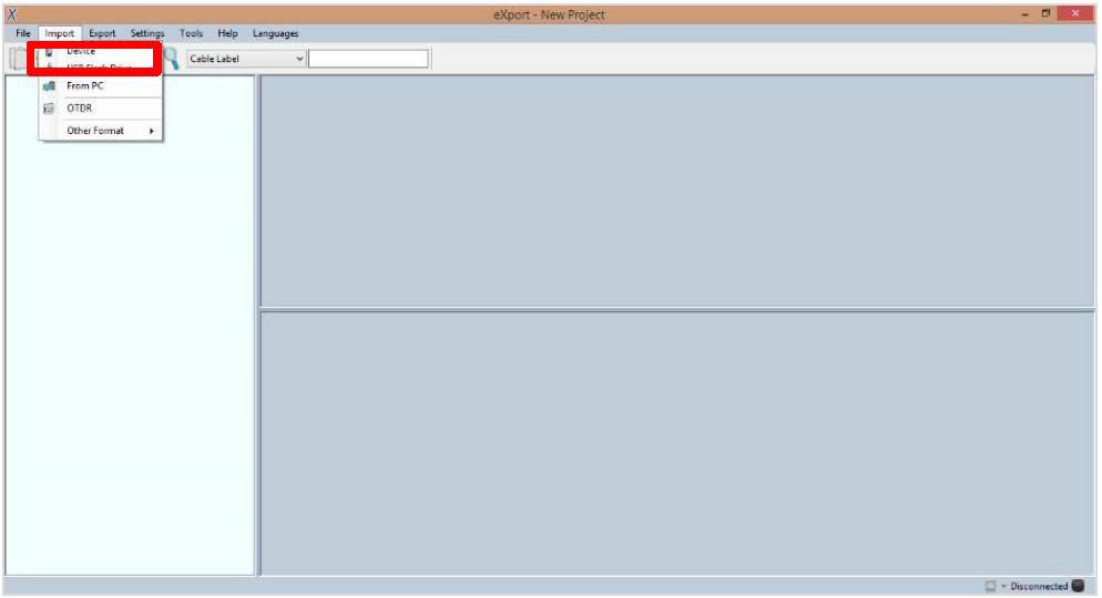
41 6. Launch export software. 7. Go to File Create New Project to create new project space. 8. Go to Import USB Flash Drive and select the flash drive. Click [Import]. 9. Select database and click [Import Selected] to import or click [Import All] for all databases. 41

42 42
43 7.4.2 Direct connection via USB cable 1. Connect WireXpert to your PC using a mini USB cable. 2. Launch export software. 3. Go to File Create New Project to create new project space. 4. Go to Import Device. 5. Select database and click [Import Selected] to import or click [Import All] for all databases. 43


44 User Manuals Refer User Manual export for more information on how to use the software. 44
45 8 Declarations 45


46 This device complies with the requirements of the EC directive 2004/108/EG Electromagnetic Compatibility (EMC directive). It meets the following requirements: Note A Declaration of Conformity in compliance with the above standards has been made and can be requested from Softing Singapore Pte Ltd. China ROHS The WireXpert device and its test components are China ROHS compliant. WEEE Electrical and electronic equipment must be disposed of separately from normal waste at the end of its operational lifetime. Please dispose of this product according to the respective national regulations or contractual agreements. If there are any further questions concerning the disposal of this product, contact Softing IT Networks. CAUTION This is a Class A product. In a domestic environment this product may cause radio interference. In that case the user may be required to take adequate measures! ROHS The WireXpert device and its test components are ROHS compliant. 46
, Multi-Mode (MM) and Encircled Flux compliant Multi-Mode (MMEF) are classified as Class 1")
47 ETL Intertek Verified WireXpert device is ETL verified to ANSI/TIA IIIe, IEC levels IIIe & IV and currently proposed Level V draft, with the applicable measurement accuracy. Class 1 Laser Product The light source transmitted from the following fiber test modules Single Mode (SM), Multi-Mode (MM) and Encircled Flux compliant Multi-Mode (MMEF) are classified as Class 1 lasers and are very low risk and safe under reasonably foreseeable use, including the use of optical instruments for intrabeam viewing. Class 1m Laser Product The light source transmitted from the following fiber test modules MPO REMOTE are classified as Class 1m lasers and have wavelengths between nm and 4000 nm, and are safe except when used with optical aids. 47
48 9 Appendix [Add] Adds a site, operator or customised cable, connector to the database. [Retest] Performs an AUTOTEST on selected result on List-Based Testing. [Back] Returns to previous screen. Unsaved options will be discarded. [Cancel] Discards option. [Delete] Deletes a site, operator or customised cable, connector from the database. [View] View selected result. [Manage] Enables [Rename] and [Select all] options. Format, Reset Performs non-reversible setting/ data restoration to factory defaults. Forward Proceed to the next screen. [Device info] Displays device firmware build information. [OK] Confirms and saves current option. [Rename] Renames saved test result in the DATA menu. [Restart] Restarts current procedure. [Save] Saves current test result. Icon will disappear after a successful save. [USB] Reads USB flash drive to perform upgrade firmware, test result export or custom limit and label list import 48
49 [Select all] Selects all data on screen. [Next pair] View next pair of plots of the current result. Fibermap Displays mapping of fiber being tested. [MPO chart/grid] Toggles between displaying of power loss in bar chart or grid format for fiber testing. [Scope live/test] Toggles between Live and Test mode when inspecting a SM/MM fiber with the inspection scope. [Set Reference] Performs result referencing between the LOCAL and REMOTE units. [Transmit ON/OFF] Toggles between enabling and disabling of light source on the REMOTE unit. 49
50 Related documents User Manual Fiber Certification Testing User Manual MPO Certification User Manual export User Guide List Based Testing User Guide Installing export PC Software Quick Start Guide Copper Certification Testing Quick Start Guide Fiber Certification Testing Quick Start Guide Encircled Flux Compliant Multimode Fiber Certification Testing Quick Start Guide MPO Certification Testing 50
51 Disclaimer of liability The information contained in these instructions corresponds to the technical status at the time of printing of it and is passed on with the best of our knowledge. The information in these instructions is in no event a basis for warranty claims or contractual agreements concerning the described products, and may especially not be deemed as warranty concerning the quality and durability pursuant to Sec. We reserve the right to make any alterations or improvements to these instructions without prior notice. The actual design of products may deviate from the information contained in the instructions if technical alterations and product improvements so require. It may not, in part or in its entirety, be reproduced, copied, or transferred into electronic media. Softing Singapore Pte Ltd Singapore Science Park 1 3 Science Park Drive Franklin, #03-09 Singapore asia-support.itnetworks@softing.com The latest version of this manual is available in the Softing download area at: 51
52 10 Technical Support THE AMERICAS Softing Inc Chapman Highway Knoxville, TN Phone: ASIA/PACIFIC Softing Singapore Pte. Ltd. 3 Science Park Drive #03-09, The Franklin Singapore Science Park 1 Singapore Phone: ext asia-sales.itnetwork@softing.com EUROPE/MIDDLE EAST/AFRICA Softing IT Networks GmbH Richard-Reitzner-Alle 6 D Haar, Munich Phone: info.itnetworks@softing.com Softing Italia Srl. Via M. Kolbe, Cesano Boscone (MI) Phone: info@softingitalia.it Softing Shanghai Room 208, Building 1, No 388, Tianlin Road Xuhui District, Shanghai, China Phone: china-sales.itnetwork@softing.com Softing SRL 87 Rue du Général Leclerc Creteil, Île-de-France (Paris) Phone: info.france@softing.com Austria Buxbaum Automation GmbH Eisenstadt Phone: office@myautomation.at Softing s global presence ensures our customers receives sales and technical support anywhere around the world. For more information : Rev. 2017_06_EMEA
User Manual Copper Certification Testing
 User Manual Copper Certification Testing User Manual Copper Certification, WireXpert v7.2, build #459 WireXpert4500_Copper_IT_EN_U_201607_104 Copyrights 2016 Softing Singapore Pte Ltd http://itnetworks.softing.com
Fiber USER MANUAL.
 Fiber USER MANUAL http://itnetworks.softing.com ENGLISH TABLE OF CONTENTS 1 Introduction... 4 1.1 About product... 4 1.2 Safety precautions... 4 1.3 Intended use... 5 1.4 About this document... 5 1.5 Before
export PC Software for WireXpert User Manual
 export PC Software for WireXpert User Manual User Manual export PC Software, v7.2 WireXpert4500_eXport_IT_EN_U_201607_203 Copyrights 2016 Softing Singapore Pte Ltd http://itnetworks.softing.com Disclaimer
North America & Canada Softing Inc. Knoxville, Tennessee Tel.: Europe/Middle East/Africa
 English North America & Canada Softing Inc. Knoxville, Tennessee Tel.: +1.865.251.5252 E-Mail: sales@softing.us Singapore Softing Singapore Pte. Ltd. Singapur Tel.: +65-6569-6019 E-Mail: asia-sales.itnetworks@softing.com
Psiber Data. WireXpert. User Manual
 Psiber Data WireXpert User Manual User Guide WireXpert v6.2.6 Rev.0 Last updated on 01-Dec-2014 Copyrights 2014 Psiber Data Pte Ltd www.psiberdata.com WX Series, (WX4500, WX500) www.psiberdata.com 2 Notices
User Manual Fiber Certification Testing
 User Manual Fiber Certification Testing User Manual Fiber Certification, WireXpert v7.1.0, build #276 WireXpert4500_Fiber_IT_EN_U_201511_102S Copyrights 2015 Softing Inc. http://itnetworks.softing.com/
Series. WireXpert Key Features. Easy to use and Ruggedized design. Fast and simple for highest productivity
 500 is an affordable and upgradable cable certification tester that can grow with your cable certification needs. Invest today only in options that are really needed and upgrade the device later when necessary.
CableMaster CM200 Compact and economic cable tester
 CableMaster CM200 Compact and economic cable tester Easy to read LCD Screen Data Cable Testing Detects shorts, opens, reversals, miswires, and split pairs Tone generator Auto power-off USER MANUAL CableMaster
Wire pert. 1st CAT8 Cable Certifier. Ethernet CABLE CERTIFIER
 Wire pert 1st CAT8 Cable Certifier The WireXpert is the first Ethernet cable certifier with capability to certify the highest performance cabling systems in enterprise networks and data centers. Cable
Quick Startup Guide. datafeed uagate SI. Version: EN Copyright 2016 Softing Industrial Automation GmbH
 Quick Startup Guide datafeed uagate SI Version: EN-052016-1.01 Disclaimer of liability The information contained in these instructions corresponds to the technical status at the time of printing of it
Deviser Part No.: TC500-DL Deviser Instruments, Inc. All rights reserved.
 TC500 Ethernet Cabling Certifier Operation Manual Version 1.13 Deviser Part No.: TC500-DL Deviser Instruments, Inc. All rights reserved. Warranty This instrument is guaranteed for a period of 2 years
Psiber Data WireXpert P R O F E S S I O N A L N E T W O R K T E S T I N G & P R O T O C O L A N A L Y S I S
 Psiber Data WireXpert Agenda Psiber Data WireXpert Introduction Company Presentation Why Cable Certification? Universal Structured Cabling or The Network Standards The WireXpert Page 2 Psiber Data Company
Wire pert. Cable Certifier. 1st CAT. e C. Cable Tester of Choice
 4500 Cable Certifier r tifie r e C e l b a C 8 1st CAT ation z i m i t p o w o fl k Now with wor The WireXpert is the first cable certifier with capability to certify the highest performance cabling systems
Complimentary Reference Material
 Complimentary Reference Material This PDF has been made available as a complimentary service for you to assist in evaluating this model for your testing requirements. TMG offers a wide range of test equipment
ANSI/TIA-568-C Cat 6A Field Test Specifications
 This document has been prepared to aid consultants or engineers in developing contractual specifications covering the certification of Category 6A Permanent Links. It is offered as a general guide. Suitability
WireScope 155 SCOPE. Agilent Wirescope 155 Specs Provided by The Performance Leader in Hand-Held Network Tools
 Agilent Wirescope 155 Specs Provided by www.aaatesters.com WireScope 155 Tests installed cabling for compliance with TIA 568A Category 5 and ISO 11801 Class D specifications. Fully implements TIA TSB-67
CableMaster CM400 Voice, Data & Video Tester
 CableMaster CM400 Voice, Data & Video Tester Tests Voice (6 wire), Data (8 wire) and Video (coax) Easy to read, extra large 7-segment LCD screen with large icons Tone generation over voice, data and video
KSD-800 Series. Installation Guide. Industrial 8-Port Fast Ethernet Switches with Fiber Connectivity DOC A -1-
 KSD-800 Series Industrial 8-Port Fast Ethernet Switches with Fiber Connectivity Installation Guide DOC.110516A -1- (C) 2005 KTI Networks Inc. All rights reserved. No part of this documentation may be reproduced
Serial PROFIBUS Interface
 Installation Manual Serial PROFIBUS Interface Version: EN-062016-2.3 Copyright 2016 Softing Industrial Automation GmbH Disclaimer of liability The information contained in these instructions corresponds
SCT2000 and SCT1500 Structured Cable Testers
 SCT2000 and SCT1500 Structured Cable Testers USER MANUAL ENGLISH 1 SAFETY WARNINGS Read First: Safety and Operational Information The international symbols used on the instrument or in this manual are
FG-260. Quick Startup Guide. Gateway between EtherNet/IP and PROFINET with PROFINET Controller functionality. Version: MMA-CA EN
 Quick Startup Guide FG-260 Gateway between EtherNet/IP and PROFINET with PROFINET Controller functionality Version: MMA-CA-010260-EN-072015-1.02 Copyright 2014-2015 Softing Industrial Automation GmbH Disclaimer
Industrial 5-Port Fast Ethernet Switches with SFP Slot and optional 4 PoE PSE Ports. Basic Model: KSD-541 PoE Model: KSD-541-P. Installation Guide
 Industrial 5-Port Fast Ethernet Switches with SFP Slot and optional 4 PoE PSE Ports Basic Model: KSD-541 PoE Model: KSD-541-P Installation Guide DOC.080104-1- (C) 2008 KTI Networks Inc. All rights reserved.
ANSI/TIA-568-C Cat 6 Field Test Specifications
 This document has been prepared to aid consultants or engineers in developing contractual specifications covering the certification of Category 6 Permanent Links. It is offered as a general guide. Suitability
TL-PA4010 AV600 Powerline Adapter
 TL-PA4010 REV2.0.0 1910011622 CONTENTS Chapter 1 Introduction... 1 1.1 System Requirement... 1 1.2 Important Safety Instructions... 1 1.3 Conventions... 2 1.4 LED Indicator... 2 1.5 Physical Interface...
Testing and Measurement Technology. Handbook of Cable Testing. Fault Analysis Documentation and Reporting. h ps://itnetworks.softing.
 Testing and Measurement Technology Handbook of Cable Testing h ps://itnetworks.softing.com Fault Analysis Documentation and Reporting Editorial On the way to new frontiers High-quality copper wiring in
AEROTRAK HANDHELD AIRBORNE PARTICLE COUNTER MODEL 9306 QUICK START GUIDE
 AEROTRAK HANDHELD AIRBORNE PARTICLE COUNTER MODEL 9306 QUICK START GUIDE Thank you for purchasing a TSI AeroTrak Model 9306 Handheld Airborne Particle Counter. This guide will help you quickly begin using
AEROTRAK PORTABLE AIRBORNE PARTICLE COUNTER MODEL 9310/9350/9510/9550/9500 QUICK START GUIDE
 AEROTRAK PORTABLE AIRBORNE PARTICLE COUNTER MODEL 9310/9350/9510/9550/9500 QUICK START GUIDE Thank you for purchasing a TSI AeroTrak Portable Airborne Particle Counter (particle counter). This guide will
Release Notes. WireXpert / export. Version 7.3 Build 854
 Release Notes WireXpert / export Version 7.3 Build 854 June 1, 2017 Version: 1.0 Page 1 of 6 1 New or enhanced features: WireXpert / Certifier Copper cable database updated Link / Berk-Tek / Leviton /Giga
USER MANUAL. Uninterruptible Power Supply Line-interactive VCL Series UPS VA. GE Critical Power
 Critical Power USER MANUAL Uninterruptible Power Supply Line-interactive VCL Series UPS 400 600 800 1000 1500 VA GE Consumer & Industrial SA General Electric Company CH 6595 Riazzino (Locarno) Switzerland
Cable Certification. General Testing Criteria (Applies to all cable certification testing) Attachment F Cable Certification
 Attachment F Cable Certification") General Testing Criteria (Applies to all cable certification testing) 1. RCIT reserves the right to be present during any or all cable testing procedures. The Contractor shall obtain authorization from
General Testing Criteria (Applies to all cable certification testing) 1. RCIT reserves the right to be present during any or all cable testing procedures. The Contractor shall obtain authorization from
Installation Guide. QBox-V6. Standalone/Spare V6 SDI QBox. Standalone/Spare V6 SDI QBox. Part No. A
 Installation Guide Standalone/Spare V6 SDI QBox QBox-V6 Standalone/Spare V6 SDI QBox Part No. A9009-0004 EN www.autocue.com Copyright 2017 All rights reserved. Original Instructions: English All rights
Cabling Infrastructure
 Introduction Ethernet Banking on Structured Cabling Technology Drivers Classification of Cables Fibre-optic cable Cables in building Cabling Infrastructure Cabling systems address the networking requirements
Quick Startup Guide. datafeed edgegate. Version: EN Copyright 2017 Softing Industrial Automation GmbH
 Quick Startup Guide datafeed edgegate Version: EN-082017-1.40 Disclaimer of liability The information contained in these instructions corresponds to the technical status at the time of printing of it and
LanTEK III FiberTEK III. Certifier for Copper and Fibre Cabling. Proof of Performance
 LanTEK III FiberTEK III Certifier for Copper and Fibre Cabling Proof of Performance LanTEK III FiberTEK III The LanTEK III is an easy to use cable certifier that meets existing TIA and ISO/IEC performance
Net-Ritef Continuity and Wiremap Tester Trace-Ritef Tone Generator and Amplified Tone Tracer User's Guide.
 Net-Ritef Continuity and Wiremap Tester Trace-Ritef Tone Generator and Amplified Tone Tracer User's Guide www.jdsu.com/know Voltage Probe Tracer/Power Button Volume Up/Down Indicator LED Power/Tone Type
Camera A14 and A34 Dome Camera
 Camera A14 and A34 Dome Camera Quick Start Guide Thank you for purchasing our product. If there are any questions, or requests, please do not hesitate to contact the dealer. About This Manual: This manual
DTM Library. Extended Field Device Access for Plant Asset Management Applications (FDT/DTM) Installation Manual. Version: EN
 Installation Manual. Version: EN") Installation Manual DTM Library Extended Field Device Access for Plant Asset Management Applications (FDT/DTM) Version: EN-012016-1.01 Copyright 2015-2016 Softing Industrial Automation GmbH Disclaimer
Installation Manual DTM Library Extended Field Device Access for Plant Asset Management Applications (FDT/DTM) Version: EN-012016-1.01 Copyright 2015-2016 Softing Industrial Automation GmbH Disclaimer
Installation Manual TH LINK PROFINET. Version: EN Copyright 2014 Softing Industrial Automation GmbH
 Installation Manual TH LINK PROFINET Version: EN-201410-1.00 Copyright 2014 Softing Industrial Automation GmbH Disclaimer of liability The information contained in these instructions corresponds to the
Installation and Operation Back-UPS BR1000G-IN / BR1500G-IN
 Installation and Operation Back-UPS BR1000G-IN / BR1500G-IN Important Safety Information Read the instructions carefully to become familiar with the equipment before trying to install, operate, service
2 Mesa Ethernet Dock User s Manual
 owner s manual Mesa Ethernet Dock The Mesa Ethernet Dock is an optional accessory that provides an ethernet port for networking, power input jack, USB client port, and a mounting station for the Mesa Rugged
TruVision IP Thermal Camera Installation Guide
 TruVision IP Thermal Camera Installation Guide P/N 1073335-EN REV B ISS 19OCT17 Copyright Trademarks and patents Manufacturer Certification 2017 United Technologies Corporation, Interlogix is part of UTC
User Manual. 400Amp AC Clamp Meter + NCV. Model MA430. Additional User Manual Translations available at
 User Manual 400Amp AC Clamp Meter + NCV Model MA430 Additional User Manual Translations available at www.extech.com Introduction Congratulations on your purchase of this Extech MA430 Clamp Meter. This
Common Mistakes Made in Certification Specifications and Testing. Jim Davis Regional Marketing Engineer Fluke Networks
 Common Mistakes Made in Certification Specifications and Testing Jim Davis Regional Marketing Engineer Fluke Networks Common Mistake #1 Failing to specify a Permanent Link test #1 Permanent Link or Channel?
LanTEK III FiberTEK III. Certifier for Copper and Fibre Cabling. Proof of Performance
 LanTEK III FiberTEK III Certifier for Copper and Fibre Cabling Proof of Performance LanTEK III FiberTEK III The LanTEK III is an easy to use cable certifier that meets existing TIA and ISO/IEC performance
Industrial 5-Port Fast Ethernet Switches. with SFP Slot and optional 4 PoE PSE Ports. Basic Model: KSD-541. PoE Model: KSD-541-HP. Installation Guide
 Industrial 5-Port Fast Ethernet Switches with SFP Slot and optional 4 PoE PSE Ports Basic Model: KSD-541 PoE Model: KSD-541-HP Installation Guide DOC.141201-1- (C) 2014 KTI Networks Inc. All rights reserved.
Model P4017 Single Channel USB Oscilloscope. Quick Start Guide
 Model P4017 Single Channel USB Oscilloscope Quick Start Guide General Warranty BNC warrants that the product will be free from defects in materials and workmanship for 3 years from the date of purchase
USB 3 Extenders. 4-Port Point-to-Point Extender System User Guide
 USB 3 Extenders 4-Port Point-to-Point Extender System User Guide Document 411-0024-30 Rev A June 2018 Contents Introduction...3 Features...3 Unpacking...3 A Quick Look at the USB 3 Extenders...4 The Local
USB 2.0 RG port USB m Cat 5e Extender System. User Guide
 USB 2.0 RG2204 4-port USB 2.0 100m Cat 5e Extender System User Guide Thank you for purchasing the USB 2.0 RG2204. Please read this guide thoroughly. This document applies to Part Numbers: 01-00294, 01-00295,
Lenovo S60-a. Quick Start Guide. Read this guide carefully before using your smartphone.
 Lenovo S60-a Quick Start Guide Read this guide carefully before using your smartphone. First glance 1 2 3 4 11 12 13 5 6 14 15 7 10 9 8 16 17 13 1 Headset connector 2 Light/Proximity sensor 3 Receiver
CF3000 Dealer Diagnostic Tool Instruction Manual
 CF3000 Dealer Diagnostic Tool Instruction Manual Table of Contents: About the CF3000......3 Important Precautions......4 Components....5 Charging the CF3000......7 Licensing the CF3000.......8 Updating
OX 5022-CK OX 5042-CK
 QUICK START USER GUIDE OX 5022-CK OX 5042-CK Statement of Compliance Chauvin Arnoux, Inc. d.b.a. AEMC Instruments certifies that this instrument has been calibrated using standards and instruments traceable
16-Port Chassis Media Converter System Manual
 16-Port Chassis Media Converter System Manual 17732-B 16-Port Media Converter (ST Connectors, Shown) INTRODUCTION This system manual describes the ADC 16-Port Media Converter with SC and ST connectors,
USB 2.0 DIGI-USB2 1-Port USB m Category 5e/6/6a/7 Extender Set with Flexible Power. User Manual. Revision
 USB 2.0 DIGI-USB2 1-Port USB 2.0 100m Category 5e/6/6a/7 Extender Set with Flexible Power User Manual Revision 171213 Thank you for purchasing the USB 2.0 DIGI-USB2. Please read this guide thoroughly.
COPYRIGHT NOTICE IDEAL INDUSTRIES LTD All rights reserved Publication ref: Issue 1-11/2015 (Applies to software revision 3.
 LanTEK III COPYRIGHT NOTICE The information contained in this document is the property of IDEAL INDUSTRIES Ltd. and is supplied without liability for errors and omissions. No part of this document may
DuoFern Multiple Wall Controller
 DuoFern Multiple Wall Controller 9494-1 Instruction manual for the electrical connection and for commissioning Item no. 3250 19 74 / Type: 9494-1 (surface-mounted with battery) VBD 663-2 (12.16) Dear Customer,
Mini Digital Multimeter
 User Manual Mini Digital Multimeter Model MN15A Additional User Manual Translations available at www.extech.com Introduction Congratulations on your purchase of the Extech MN15A MultiMeter. The MN15A offers
TRC-190 User s Manual
 User s Manual Edition 3.2, May 2017 www.moxa.com/product 2017 Moxa Inc. All rights reserved. User s Manual The software described in this manual is furnished under a license agreement and may be used only
EVO-TM2A EVO-TM2B Touch Screen Monitor
 User Manual Revision v1.3 Dec. 2010 EVO-TM2A EVO-TM2B Touch Screen Monitor Copyright 2010 August All Rights Reserved Manual Version 1.3 Part Number: The information contained in this document is subject
PoE Powered Gigabit Ethernet Media Converters 1000BASE-T TO 1000BASE-SX/LX. KGC-352 Series. Installation Guide
 PoE Powered Gigabit Ethernet Media Converters 1000BASE-T TO 1000BASE-SX/LX KGC-352 Series Installation Guide DOC.070820-KGC-352-1- (C) 2007 KTI Networks Inc. All rights reserved. No part of this documentation
Micro-Ohmmeter Model 6292
 Micro-Ohmmeter Model 6292 Quick Start Guide ENGLISH www.aemc.com CHAUVIN ARNOUX GROUP Statement of Compliance Chauvin Arnoux, Inc. d.b.a. AEMC Instruments certifies that this instrument has been calibrated
Operating Instructions for Orderman Sol & Sol+
 Operating Instructions for Orderman Sol & Sol+ 2010 by Orderman GmbH Bachstrasse 59, 5023 Salzburg Austria www.orderman.com Errors and misprints excepted. Duplication, reproduction or distribution, even
Colorado Series. CR-10 Portable ph / mv / Temperature Meter Operation Manual
 Colorado Series CR-10 Portable ph / mv / Temperature Meter Operation Manual 2 Contents Page General Introduction and Initial Inspection.............................. 4 Safety Infomation..................................................
CncGcoder Models HD & HDx Manual
 CncGcoder Models HD & HDx Manual Table of Contents WELCOME... 3 IN THE BOX... 4 Optional Accessories...4 HANDHELD OVERVIEW... 5 Overview...5 Charging the Battery...6 Turning On and Off...6 Plugging in
FOCIS Flex - No Wireless Fiber Optic Connector Inspection System User Guide
 Test & Inspection FOCIS Flex - No Wireless Fiber Optic Connector Inspection System User Guide www.aflglobal.com or (800) 321-5298, (603) 528-7780 Table of Contents Safety Information....3 How to View Device
USB Raven Port USB 3.1, 200m Multimode Fiber Point-to-Point Extender System User Guide
 USB 3-2-1 Raven 3124 4-Port USB 3.1, 200m Multimode Fiber Point-to-Point Extender System User Guide Thank you for purchasing the USB 3-2-1 Raven 3124. Please read this guide thoroughly. This document applies
Important Information KX-NTV150. Communication IP Camera. IP Video Doorphone. Model No. Model No. KX-NTV160
 Important Information Communication IP Camera Model No. KX-NTV150 IP Video Doorphone Model No. KX-NTV160 Thank you for purchasing this Panasonic product. Please read this Important Information carefully
Emerson Network Power provides customers with technical support. Users may contact the nearest Emerson local sales office or service center.
 Liebert PSA iton User Manual Version: V2.8 Revision date: November 14, 2005 Emerson Network Power provides customers with technical support. Users may contact the nearest Emerson local sales office or
USB Raven Port USB 3.1, 100m CAT 6a/7 Point-to-Point Extender System User Guide
 USB 3-2-1 Raven 3104 4-Port USB 3.1, 100m CAT 6a/7 Point-to-Point Extender System User Guide Thank you for purchasing the USB 3-2-1 Raven 3104. Please read this guide thoroughly. This document applies
Tabel of Content. What s in the Box 01. Feature Introduction 02. Setting Up the Camera and Monitor 03. Replacing the Camera lens 11.
 Tabel of Content What s in the Box 01 Feature Introduction 02 Setting Up the Camera and Monitor 03 Replacing the Camera lens 11 Safety 12 Customer service 15 What s in the Box Feature Introduction Monitor
USER MANUAL. Mini Multimeter with Non-Contact Voltage Detector (NCV) Model EX310
 Model EX310") USER MANUAL Mini Multimeter with Non-Contact Voltage Detector (NCV) Model EX310 Introduction Congratulations on your purchase of the Extech EX310 MultiMeter. The EX310 offers AC/DC Voltage, AC/DC Current,
USER MANUAL Mini Multimeter with Non-Contact Voltage Detector (NCV) Model EX310 Introduction Congratulations on your purchase of the Extech EX310 MultiMeter. The EX310 offers AC/DC Voltage, AC/DC Current,
USB 3.1 CAT6A/7 EXTENDER
 USER MANUAL ICU504A USB 3.1 CAT6A/7 EXTENDER 24/7 AT OR VISIT BLACKBOX.COM Power Mode Config Status Link Video USB 2 USB 3 Power Mode Config Status Link Video USB 2 USB 3 TABLE OF CONTENTS PRODUCT OPERATION
Chapter 3 Certifying Twisted Pair Cabling
 Chapter 3 Certifying Twisted Pair Cabling Setting the Reference The reference procedure sets a baseline for insertion loss, ELFEXT, and dc resistance measurements. Run the tester s reference procedure
Owner s Instruction Manual
 Owner s Instruction Manual Advanced Healthcare Telephone Model 5150 Contents IMPORTANT SAFETY INSTRUCTIONS...3 BOX CONTENTS...4 FEATURES...4 ON/OFF SWITCH...4 DIAL BUTTONS...4 RECEIVER VOLUME CONTROL...4
MEEM Memory Ltd. User Guide ios
 MEEM Memory Ltd. User Guide ios 1. MEEM AT A GLANCE Meem Overview This guide describes the features of MEEM and MEEM App. MEEM automatically backs up your phone onto MEEM itself, every time you charge
BEETLE /Fusion Compact. Installation Guide
 BEETLE /Fusion Compact Installation Guide The reproduction, transmission or use of this document or its contents is not permitted without express authority. Offenders will be liable for damages. All rights,
SECTION TELECOMMUNICATIONS TESTING AND DOCUMENTATION
 SECTION 17045 TELECOMMUNICATIONS TESTING AND DOCUMENTATION PART 1 - GENERAL 1.1 RELATED DOCUMENTS A. Drawings and general provisions of the Contract, including Facilities Management Design and Construction
Operating Instructions
 PRIMETEST 100 PRIMETEST 100 Bracken Hill South West Industrial Estate Peterlee Co Durham SR8 2SW ENGLAND Tel: +44(0)191 5863511 www.seaward.co.uk sales@seaward.co.uk service@seaward.co.uk Part Number
USER GUIDE. AXIS T8120 Midspan 15 W 1-port ENGLISH
 USER GUIDE AXIS T8120 Midspan 15 W 1-port ENGLISH Legal Considerations Video and audio surveillance can be prohibited by laws that vary from country to country. Check the laws in your local region before
User Guide True RMS Multimeter Extech EX205T
 User Guide Extech EX205T True RMS Digital Multimeter Extech EX210T True RMS Digital Multimeter IR True RMS Multimeter Extech EX205T Introduction Thank you for selecting the Extech EX205T True RMS Auto-ranging
IMPORTANT SAFETY INSTRUCTIONS SAVE THESE INSTRUCTIONS
 IMPORTANT SAFETY INSTRUCTIONS IMPORTANT SAFETY INSTRUCTIONS SAVE THESE INSTRUCTIONS WARNING (SAVE THESE INSTRUCTIONS): This manual contains important instructions that should be followed during installation
2 in 1 LAN Tester and Multimeter Model:
 2 in 1 LAN Tester and Multimeter Model: 72-8495 1 IMPORTANT SAFETY INFORMATION Please read these instructions carefully before use and retain for future reference. This instrument is designed and manufactured
Operation Manual Locator Wöhler L 200
 Operation Manual Locator Wöhler L 200 Best.-Nr. 22849 2014-12-18. Contents Contents 1 General Information... 3 1.1 Operation Manual Information... 3 1.2 Notes in this manual... 3 1.3 Proper use... 3 1.4
Quick Start Guide CJB1950ALAAB
 Quick Start Guide 1 CJB1950ALAAB www.sar-tick.com This product meets applicable national SAR limits of 2.0W/kg. The specific maximum SAR values can be found in the section of this user guide. When carrying
DS-1H05 Ethernet-over-Coax Extender. User Manual
 DS-1H05 Ethernet-over-Coax Extender User Manual Thank you for purchasing our product. If there is any question or request, please do not hesitate to contact dealer. This manual is applicable to DS-1H05-T,
CableMaster 600/650 Full-Color Cable Testing and Report Management
 CableMaster 600/650 Full-Color Cable Testing and Report Management DESCRIPTION Displays length measurement for each pair in feet or meters using TDR technology Detects presence of PoE and mode of PoE per
USB 2.0 CAT5E/6/7 EXTENDER
 USER MANUAL IC402A-R2 USB 2.0 CAT5E/6/7 EXTENDER 24/7 AT OR VISIT BLACKBOX.COM + + + + Mode Config Power Link Host Activity Power Link Host Activity TABLE OF CONTENTS PRODUCT OPERATION AND STORAGE... 3
User Manual Back-UPS Pro BN 1100/1350/1375/1400/1500 M2 BN 1100/1350/1500 M2-CA
 User Manual Back-UPS Pro BN 1100/1350/1375/1400/1500 M2 BN 1100/1350/1500 M2-CA Safety and General Information Inspect the package contents upon receipt. Notify the carrier and dealer if there is any damage.
Operating Instructions
 Bracken Hill South West Industrial Estate Peterlee Co Durham SR8 2SW ENGLAND Tel: +44(0)191 5863511 www.seaward.co.uk sales@seaward.co.uk service@seaward.co.uk Part Number 344A550 Revision 1 2006 Seaward
LanTEK II Series Manual
 LanTEK II Series Manual 0 LanTEK II Cable Certifier Instruction Manual This instruction manual contains information proprietary to IDEAL INDUSTRIES, INC. The information in this document is not to be used
TF-3239DL 10/100Mbps PCI Network Adapter
 Rev: 1.1.0 1910010553 COPYRIGHT & TRADEMARKS Specifications are subject to change without notice. is a registered trademark of TP-LINK TECHNOLOGIES CO., LTD. Other brands and product names are trademarks
Manual Version: V1.00. Video Decoder User Manual
 Manual Version: V1.00 Video Decoder User Manual Thank you for purchasing our product. If there are any questions, or requests, please do not hesitate to contact the dealer. Copyright Copyright 2016 Zhejiang
INDUSTRIAL 1000BASE-T TO 1000BASE-X MEDIA CONVERTERS. KCD-400 Series. Installation Guide
 INDUSTRIAL 1000BASE-T TO 1000BASE-X MEDIA CONVERTERS KCD-400 Series Installation Guide DOC.060227-KCD-400-1- (C) 2005 KTI Networks Inc. All rights reserved. No part of this documentation may be reproduced
Camera. Network Bullet Camera. Quick Operation Guide
 Camera Network Bullet Camera Quick Operation Guide 1 Thank you for purchasing our product. If there are any questions, or requests, please do not hesitate to contact the dealer. About This Document This
Mid-span 802.3af PoE Injector. Installation Guide KPOE-100
 Mid-span 802.3af PoE Injector Installation Guide KPOE-100 Doc. 070521 1 (C) 2005 KTI Networks Inc. All rights reserved. No part of this documentation may be reproduced in any form or by any means or used
Network Camera. Quick Guide DC-B1203X. Powered by
 Network Camera Quick Guide DC-B1203X Powered by Safety Precautions English WARNING RISK OF ELECTRIC SHOCK DO NOT OPEN WARNING: TO REDUCE THE RISK OF ELECTRIC SHOCK, DO NOT REMOVE COVER (OR BACK). NO USER-SERVICEABLE
CTS-iCPE Gateway Controller User s Manual Version: Revision B1
 CTS-iCPE Gateway Controller User s Manual Version: Revision B1 Trademarks Contents are subject to revision without prior notice. All other trademarks remain the property of their respective owners. Copyright
Installation Job Aid for VSP 4850GTS
 Installation Job Aid for VSP 4850GTS Notices Release 6.1.0.0 NN46251-308 Issue 02.01 November 2017 Notice paragraphs alert you about issues that require your attention. The following paragraphs describe
4170 POS System Installation Guide
 4170 POS System 4170 Installation Guide Thank you for selecting UTC RETAIL s innovative Model 4170 Point of Sale solution! This Installation Guide will help you efficiently install the 4170 POS. The document
LG Electronics BLUETOOTH Mono Headset HBM-210 User manual
 English Español LG Electronics BLUETOOTH Mono Headset HBM-210 User manual All rights reserved. LG Electronics Inc., 2009 Note : For the best performance and to prevent any damage to, or misuse of the HBM-210,
Instruction Manual. Anker USB 3.0 Docking Station
 Instruction Manual Anker USB 3.0 Docking Station ABOUT THIS MANUAL This manual provides a beginner's introduction to installing, configuring, and using the USB 3.0 Display Dock. Information in this document