HY-TB3DV-S intelligent 3-axis drive board manual
|
|
|
- Doris Nicholson
- 5 years ago
- Views:
Transcription
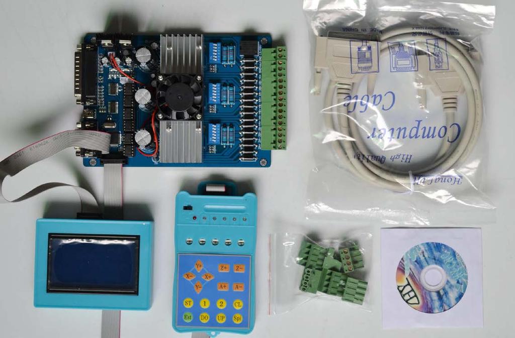
1 HY-TB3DV-S intelligent 3-axis drive board manual Thank you for choosing our company's products, the use of CNC products better and faster for you, please read this manuai Features: Features 1: integrated high-speed microcomputer intelligent control chip, with plug-in LCD display and hand, automatically detect the computer to automatically control the movement of the shield handle control functions, digital can simultaneously track record computer data and handle control mobile data 5: The driver XYZ-axis or Z axis of the knife can be done automatically, without complex computer software operation 6: up to 5A stepper motor drive current, adjustable. 7: up to 16 segments, more accurate, run more smoothly. 8: overload automatic protection function of the flow through the warm, protect your computer and peripherals. 9: bipolar constant-current chopper drive, low speed creeping phenomenon, noise, non-resonant region. 10: a closed optical isolation, two-stage signal processing, to fully protect your computer and equipment. 11:1 the road 0-10V/PWM governor signal output. 12: Rd input control, you can set the limit stop, which is divided into the knife. Electrical properties (ambient temperature Tj = 25 ): Input power 12-48V DC power supply
 Driven Bipolar constant-current PWM drive output")
 Weight About 300")
2 Output current 4.5A (peak 5A) Driven Bipolar constant-current PWM drive output approach The drive motor 42,57,86 stepper motor, two-phase -4 phase (4-wire, 6 wire, 8 wire stepper motor) Weight About 300 g. Breakdown of table: Signal waveform and timing


3 Power output interface functions Interface marked detail in Figure

4


5 Instructions: 1: The coordinates of display range / : automatically records the computer running coordinates and manually move the coordinates 3: Automatic switch between computer and manual control 4: computer-controlled automatically shielded manual control functions, two seconds after the return to manual function 1: ST button to press the handle into the lower-level setup

6 menu, the setup is complete press the OK button to return to the main work interface 2: Press the corresponding axis of the handle CL button four axis clear 0, according to the B1 replaced a line, press the OK button to exit the clear 0 3: The four-axis real-time recording computer running coordinates and manually move the coordinate value of the computer running data + manually move data =================================================== 1: all settings automatic permanent preservation until the next set of updates 2: You can set the radius, put a knife height parameters 3: The driver auto-complete the knife, without the complexity of computer software operation, convenient tool change school knife, boot knife, batch processing adequately protected on the knife and other processed products correctly 1: In order to ensure the accuracy of the knife, the knife before check put a knife to the height of the parameters of the tool diameter is set correctly, 2: the need to make sure the knife instrument wiring and


7 limit switch wiring status is normal. 3:B2 keys and press to confirm OK to enter the automatic tool operation and automatically stop after the completion of 4: Press the keyboard (A-) exit status of the school knife ==================================================== ; All settings automatically saved permanently, until the next set update ; All settings automatically saved permanently, until the next set update


8 ; ; All settings automatically saved permanently, until the next set update ; All settings automatically saved permanently, until the next set update

9 ; All settings automatically saved permanently, until the next set update 1: ST button press the handle into the lower settings menu, the setup is complete press the OK button to return to the main interface of 2: shift downstream handle B1 button settings, 3: handle B2 button corresponding anti-white set at function selection 4: input handles digital keys to set the digital parameters Before the test machine, please note the following 1,A test machine first to 12V voltage test machine, 42-step, please with 12-16V/DC power 57 stepper choose 16-24V/DC power, 86 stepper election 24-36V/DC power 2,the stepper motor power and current (model) 3, to determine the wiring of the stepper motor 二 The pin definitions
10 1 Parallel port control is defined as follows: PIN14 PIN1 PIN3 PIN2 PIN1 PIN5 PIN4 PIN1 PIN7 PIN6 PIN16 Relay X Allow X Direct ion X Pulse Y Allow Y Direct ion Y Pulse Z Allow Z Direct ion Z Pulse 0-10V PWM 2 Limit 1 ~ PIN9 defined as follows (figures defined inside the interface marked) X-axis limit Y-axis limit Emergency stop Z-axis limit Alternative input DC- InterfaceP1 InterfaceP2 Interface P3 Interface P4 Interface P5 Interface P6-P9 Thecorresponding computerp12 Corresponding computerp13 Corresponding computer P15 Corresponding computer P11 Corresponding computer P10 GND 3 Output interface is defined (in the picture for 22 to 1) P1 P2 P3 P4 P5 P6 P7 P8 P9 P1 P1 P1 P1 P1 P1 P1 P 正地 M G M X X X X YA YA Y Y ZA ZA ZB ZB O N O A+ A- B+ B- + - B+ B D - Power is connected to 12 48V 8A (Optional according to the stepper motor operating current) above switching power supply, received marked on the power input interface 12V power output is used to pick up the 12V cooling fan 三 MACH software using the method

11 Figure1 Figure 1, open the MACH3 software, now mach3mill then select OK Figure 2 MACH3 open the interface shown in Figure 2, above the action button, where we first configure the MACH software

12 Figure 3 Figure 3, open the config menu PORT PIN menu Figure 4

13 Figure 4 Set on the circle a place where you can set the fundamental frequency, this parameter of the motor rotation speed. Set up, select the circle place, the configuration of the definition of the foot, as shown in Figure5 Figure5 According to the definition of the parallel port of the board, follow the map circle to indicate the definition modify the software settings

14 Figure 6 Then part in the selection output signals, as shown in Figure 6, according to the settings of the circle, set the appropriate
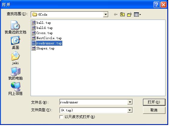
15 Figure 7 All set ok, you can open the G code need to run, as shown in Figure7
16 Figure 8

17 Figure 9 Open the G code, you can see the red the RESET flashing, you can use the mouse to click this RESET to stop flashing, then you can press circle the location CYCLESTART run.
Thank you for choosing our company's products, the use of CNC products better and faster for you, please read this manual
 HY-TB3DV-HH(HL) 3-axis drive board manual Product Link: http://www.thanksbuyer.com/cnc-very-professiona l-3-axis-3-5a-tb6560-stepping-motor-driver-cont roller-lcd-display-cnc-router-24898 Thank you for
HY-TB5 CNC Series Manual five axis
 HY-TB5 CNC Series Manual ------ five axis Thank you for choosing our products better and faster for you to use NC products, please read this manual, make sure the pump is started before the water-cooled
Thank you for choosing our products better and faster operational
 Aerospace TB3-axis drive board H-TB3DV-M Instructions Thank you for choosing our products better and faster operational numerical control for you, please read this manual Products Features 1 The maximum
User Guide for 4 axis TB6560 driver board
 User Guide for 4 axis TB6560 driver board Product Features: Toshiba TB6560AHQ chip - High power, maximum 3.5A drive current chipset! 1-1/16 microstep setting - Higher accuracy and smoother operation than
User Guide for 3 axis TB6560 driver boar d
 User Guide for 3 axis TB6560 driver boar d Product Features: Toshiba TB6560AHQ chip - High power, maximum 3.5A drive current chipset! 1-1/16 microstep setting - Higher accuracy and smoother operation than
User Guide for 4 axis TB6560 driver board. *Important Note*: Please strictly follow the setting photos for configuration
 User Guide for 4 axis TB6560 driver board Settings of MACH3 *Important Note*: Please strictly follow the setting photos for configuration in Mach3! Fig.1 Open MACH3 software, select mach3mill, and then
CHANGZHOU WANTAI ELECTRICAL APPLIANCE CO., LTD. User Guide for 3 axis TB6560 driver board
 CHANGZHOU WANTAI ELECTRICAL APPLIANCE CO., LTD Product Features: User Guide for 3 axis TB6560 driver board Toshiba TB6560AHQ chip - High power, maximum 3.5A drive current chipset 1-1/16 microstep setting
CNCtak.com CNCtak.com CNCtak.com
 1 User Guide for 4 axis TB6560 driver board เป นส นค าจากประเทศจ น ท ม จ ดเด นของ DRIVER BOARD ของ Toshiba TB6560AHQ chip ตามรายละเอ ยด Block Diagram Toshiba TB6560AHQ chip Product Features: 1.Toshiba
User Manual. For 3rd Generation. 5 Axis Standard & Professional Breakout Board Set
 The 3 rd Generation 5 Axis Breakout Board Set User Manual For 3rd Generation 5 Axis Standard & Professional Breakout Board Set Attention: Please read the manual carefully before using the products! Email:
Profi4 Main Board Manual
 Profi4 Main Board Manual A. Scope of application It is used to run the signal processing of the host computer ( LPT port ), with MACH 3 CNC system software, and the peripheral machine dynamic electrical.
TB6560HQ T3-V5 2.5A 3 AIXS DRIVER USER MANUAL WITH MANUL CONTROL TYPE
 TB6560HQ T3-V5 2.5A 3 AIXS DRIVER USER MANUAL WITH MANUL CTROL TYPE Catalogue TB6560HQ T3-V5...1 2.5A 3 AIXS DRIVER USER MANUAL WITH MANUL CTROL TYPE...1 1. Overview...2 2. TB6560AHQ advantage...3 2.1
User's Manual. For ST-6560V3. Version All Rights Reserved
 User's Manual For ST-6560V3 Version 2.0 2016.08.25 All Rights Reserved 1. Key Features Toshiba TB6560AHQ chip - High power, maximum current 3.5A Resolution 1, 1/2, 1/8, 1/16 micro stepping output Working
Datasheet MX Axis Stepper Drive with Breakout Board & I/O s. Version1.0
 Datasheet MX3660 3-Axis Stepper Drive with Breakout Board & I/O s Version1.0 1. Features Power up to 3 stepper motors of NEMA 17, 23, 24, or 34 Sophisticated stepper motor control based on latest DSP technology
4-Axis TB6560 CNC Driver Board Users Manual. 1.1 Scope General Description Photo of 4-AXIS CNC Board Key Features...
 Content 4-Axis TB6560 CNC Driver Board Users Manual 1. General Information... 2 1.1 Scope... 2 1.2 General Description... 2 2. Descriptions of 4-AXIS CNC Board... 2 2.1 Photo of 4-AXIS CNC Board... 2 2.2
TB6560 mach3 cnc Stepper Motor Controller operation instruction
 TB6560 mach3 cnc Stepper Motor Controller operation instruction CONTENT Ⅰ FEATURES OF TB6560...3 Ⅱ APPLICATIONS:...3 Ⅲ ELECTRICAL DRAWING...4 V DEFINITION ON PINS OF PARALLEL PORT...5 VI.ADJUSTING CURRENT
CNCMARKETİM. TB6560HQT4-v3 4 AXIS DRIVER USER MANUAL
 TB6560HQT4-v3 4 AXIS DRIVER USER MANUAL 1 Catalogue... 1 1. Overview...Hata! Yer işareti tanımlanmamış. 2. TB6560AHQ advantag... 2 2.1 At low speed operation System Advantages... 3 2.2 In high-speed operation
TB6560HQT4-v3 4 AXIS DRIVER USER MANUAL
 TB6560HQT4-v3 4 AXIS DRIVER USER MANUAL Catalogue...1 1. Overview... Error! Marcador no definido. 2. TB6560AHQ advantag...2 2.1 At low speed operation System Advantages...3 2.2 In high-speed operation
User Manual of 5Axis Breakout Board
 WWW.VALLDER.COM User Manual of 5Axis Breakout Board Safety Statement Vallder Ltd is not liable or responsible for any accidents, injuries, equipment damage, property damage, loss of money or loss of time
User Manual For DM332T. 2-Phase Digital Stepper Drive. Designed by StepperOnline. Manufactured by Leadshine
 User Manual For DM332T 2-Phase Digital Stepper Drive Designed by StepperOnline Manufactured by Leadshine #7 Zhongke Road, Jiangning, Nanjing, China T: 0086-2587156578 Web site: www.omc-stepperonline.com
Preliminary Datasheet MX Axis Stepper Drive with Breakout Board & I/O s. Preliminary V1.0
 Preliminary Datasheet MX4660 4-Axis Stepper Drive with Breakout Board & I/O s Preliminary V1.0 Features Power up to 4 stepper motors of NEMA 17, 23, 24, or 34 Sophisticated stepper motor control based
SDM / 4 Phase Stepper Drive Module. Compact Size & High Power Density, 20-60VDC, 6A Peak. Version 1.0
 SDM660 2 / 4 Phase Stepper Drive Module Compact Size & High Power Density, 20-60VDC, 6A Peak Version 1.0 http://www.leadshine.com / http://www.leadshineusa.com 2013 Leadshine Technology Co., Ltd. 3/F,
TECHNICAL REFERENCE BSD V-3A Bipolar Stepper Driver
 TECHNICAL REFERENCE BSD 3630 36V-3A Bipolar Stepper Driver Contents Chapter 1 Safety Precautions.. 3 Chapter 2 Drive Overview...4 2.1 Key Features...4 2.2 Drive Description...4 2.3 Applications. 4 Chapter
Datasheet MX Axis Stepper Drive with Breakout Board & I/O s. Version
 Datasheet MX3660 3-Axis Stepper Drive with Breakout Board & I/O s Version 1.1 http://www.leadshine.com http://www.leadshineusa.com 2013 Leadshine Technology Co., Ltd. Notice This manual is not for use
3-Axis Stepper Drive Datasheet MX3660
 3-Axis Stepper Drive Datasheet MX3660 3-Axis Stepper Drive + Breakout Board, 20-60VDC, 6A Peak Version 0.0.2 http://www.leadshine.com Features Three individual stepper drive boards Suitable for NEMA17
1. Key Features. 2. Photo of 4-AXIS CNC Board
 This document describes the basic functionality and the electrical specifications of StepperOnline s Four Axis TB6600 CNC Driver Board. 1. Key Features Supports MACH3, KCAM4, EMC2 etc Can drive four channels
DDUM CARD V1.0 Simple Description (English)
") DDUM CARD V1.0 Simple Description (English) Chapter 1 Overview 1.1 Simply Introduction 1.2 Requirements of Computer 1.3 Appearance and size of poduct 1.4 Notes and Cautions Chapter 2 Detailed Features
DDUM CARD V1.0 Simple Description (English) Chapter 1 Overview 1.1 Simply Introduction 1.2 Requirements of Computer 1.3 Appearance and size of poduct 1.4 Notes and Cautions Chapter 2 Detailed Features
Draft. CNC Controller Datasheet. 1 Features. 2 Applications
 1 Features 4-axis stepper motor control 2 general purpose 15 amp switched load outputs 12-36 VDC power supply Up to 15 amps output current. Plug compatible with standard Mean Well power supply Up to 6
Hardware Installation Manual MX Axis Stepper Drive with Breakout Board & I/O s
 Hardware Installation Manual MX3660 3-Axis Stepper Drive with Breakout Board & I/O s Version 1.0 11 / 2013 Hardware Manual for MX3660 3-Axis Stepper Drive with Breakout Board & I/O s ii Notice Read this
USER S MANUAL. CNC Servo Stepper Motor Control Box CH4EV12-1 Rev. 1
 USER S MANUAL CNC Servo Stepper Motor Control Box CH4EV12-1 Rev. 1 January, 2013 i USER'S MANUAL TABLE OF CONTENTS Page # Contents 1.0 FEATURES... 1 2.0 SPECIFICATIONS... 2 3.0 SYSTEM REQUIREMENTS... 2
PP-BOB2-V1.0 PARALLEL PORT BREAKOUT BOARD
 PP-BOB2-v1 PARALLEL PORT BREAKOUT BOARD Document: Operation Manual Document #: T17 Document Rev: 2.0 Product: PP-BOB2-v1.0 Product Rev: 1.0 Created: March, 2013 Updated: Dec, 2014 THIS MANUAL CONTAINS
TB6560 3axis mach3 cnc Stepper Motor Controller operation instruction
 TB6560 3axis mach3 cnc Stepper Motor Controller operation instruction 1 Content TB6560 3axis mach3 cnc Stepper Motor Controller operation instruction...1 I. features of TB6560...3 Ⅱ Applications:...3 Ⅲ
Novusun Controller Wiring and MACH3 Software Setup
 Novusun Controller Wiring and MACH3 Software Setup V1.0 01 2019 Open Source Mechatronics LTD 2019 Safety Statement The author of this document is not liable or responsible for any accidents, injuries,
uservo box instruction manual
 Safety notes uservo box instruction manual Every machine controlled by computer (PC) can be really dangerous for human life and health. Comply with bolow rules and use Your common sense while working with
Datasheet MX Axis Stepper Drive with Breakout Board & I/O s. Version
 Datasheet MX4660 4-Axis Stepper Drive with Breakout Board & I/O s Version 1.0 http://www.leadshine.com http://www.leadshineusa.com 2014 Leadshine Technology Co., Ltd. Notice This document is not for use
1. Key Features. 2. Photo of 4-AXIS CNC Board
 This document describes the basic functionality and the electrical specifications of StepperOnline s Four Axis TB6600 CNC Driver Board. 1. Key Features Supports MACH3, KCAM4, EMC2 etc Can drive four channels
I.CH Brushless DC Motor Driver
 V II 20100513 I.CH Brushless DC Motor Driver I.CH MOTION CO., LTD MOTION WORLD Characteristic : This control system with perfect function, simple operation, capability of anti-interference, energy saving,
PP-BOB2-V2.0 PARALLEL PORT BREAKOUT BOARD
 PP-BOB2-V2 PARALLEL PORT BREAKOUT BOARD Document: Operation Manual Document #: T18 Document Rev: 1.0 Product: PP-BOB2-V2.0 Product Rev: 1.0 Created: October, 2015 THIS MANUAL CONTAINS INFORMATION FOR INSTALLING
Manual 5 Axis CNC Interface Breakout Board Model#-DB25-1R5AM
 Manual 5 Axis CNC Interface Breakout Board Read this manual carefully before making connections to the board. Store this manual away for further reference. Safety Notes: The electronics of the control
CNC4X35A 4 axis Stepper Motor Control Board
 CNC4X35A 4 axis Stepper Motor Control Board Just connect bipolar stepper motors, power and a parallel port signal source CNC4X35A 4 axis Stepper Motor Control Board Specs: Designed for easy construction/retrofit
Three Axis CNC Driver Users Manual
 Three Axis CNC Driver Users Manual Revision 1.2 June 14. 2007 1 Content 1. GENERAL INFORMATION... 3 1.1. Scope... 3 1.2. General Description... 3 1.3. Features... 3 2. Descriptions of 3-AXIS CNC Board...
Manual of 2-phase hybrid stepper motor driver DQ542MA
 Manual of 2-phase hybrid stepper motor driver DQ542MA Introduction: DQ542MA is a type of two-phase hybrid stepping motor driver, the drive voltage of which is from 18VDC to 5VDC. It is designed for use
Overview Included in the Box: Pinout Installation Power Supply Stepping Motors DIP Switch (JP1) Location...
 Location...") DRV7 USERS GUIDE Overview... 3 Included in the Box:... 4 Pinout... 4 Installation... 5 Power Supply... 6 Stepping Motors... 8 DIP Switch (JP1) Location... 9 Setting the Output Current (JP1)... 9 Microstep
DRV7 USERS GUIDE Overview... 3 Included in the Box:... 4 Pinout... 4 Installation... 5 Power Supply... 6 Stepping Motors... 8 DIP Switch (JP1) Location... 9 Setting the Output Current (JP1)... 9 Microstep
USER S MANUAL. CNC Stepper Motor Control Box CS3EA4-1 Rev. 1
 USER S MANUAL CNC Stepper Motor Control Box CS3EA4-1 Rev. 1 April, 2012 USER'S MANUAL TABLE OF CONTENTS Page # Contents 1.0 FEATURES... 2 2.0 SPECIFICATIONS... 3 3.0 SYSTEM REQUIREMENTS... 3 4.0 WARNING...
IO3-R2 BREAKOUT BOARD
 IO3-R2 BREAKOUT BOARD DESCRIPTION Breakout board IO3-R2 (Revision R2) has digital buffer for STEP/DIR/ENA command signals and as such it is particularly suitable for the connection up to 4 microstep drives
Comprehensive support USB hot-swappable, USB connection at any time to monitor the state, Mach3 work
 USB motion control card installation manual The card features: Supports all versions of Mach3, including the latest version of Mach3 R3.042.040. Supports all versions of Windows, including the latest version
User Manual DM556T. 2 Phase Digital Stepper Drive. Designed by StepperOnline Manufactured by Leadshine 2017 All Rights Reserved
 User Manual DM556T 2 Phase Digital Stepper Drive Designed by StepperOnline Manufactured by Leadshine 2017 All Rights Reserved Address: #7 Zhongke Road, Jiangning, Nanjing, China Tel: 0086-2587156578 Web:
C35- QUICK SETUP BREAKOUT BOARD Rev. 1.1
 C35- QUICK SETUP BREAKOUT BOARD Rev. 1.1 User manual Rev. 1 1. Overview This card provides an easy way of interfacing your inputs and outputs from the parallel port. It provides terminals and RJ45 for
USER S MANUAL. C33 - MULTIFUNCTION ROUTER BOARD BOARD Rev. 4
 USER S MANUAL C33 - MULTIFUNCTION ROUTER BOARD BOARD Rev. 4 June 2013 USER'S MANUAL TABLE OF CONTENTS Page # Contents 1.0 OVERVIEW... 3 2.0 FEATURES... 3 3.0 SPECIFICATIONS... 4 4.0 FUNCTIONAL BLOCK DIAGRAMS...
PSR5042. Stepper Motor Drive User s Manual. Version 1.0. Contacts: Technical support: Sales information:
 This manual contains reserved and proprietary information. All rights are reserved. It may not be copied, disclosed or used for any purposes not expressly authorized by PrimoPal Motor. PrimoPal Motor reserves
C33- MULTIFUNCTION ROUTER BOARD Rev. 2
 C33- MULTIFUNCTION ROUTER BOARD Rev. 2 User manual Rev. 1 1. Overview This card provides an easy way of interfacing your router based spindle with your steeper motor driver board. This board includes a
2. Computer system requirement Minimum configuration: 1) CPU:1GHz 2) Memory: 512MB 3) 500MB free disk space
 CPU:1GHz 2) Memory: 512MB 3) 500MB free disk space") 1. Products brief introduction USBCNCV4.0 is a high performance motion controller which based on PC software USBCNC control, the system can complete the conversion from G code to connect stepper motor
1. Products brief introduction USBCNCV4.0 is a high performance motion controller which based on PC software USBCNC control, the system can complete the conversion from G code to connect stepper motor
MSD325 Microstepping Drive
 MSD325 Microstepping Drive Introduction MSD325 is a very small size microstepping drive based on most advanced technology in the world today. It is suitable for driving any 2-phase and 4-phase hybrid stepper
Routout CNC 3 Axis Plug & Play Controller Data Sheet Version 1.1
 Routout CNC 3 Axis Plug & Play Controller Data Sheet Version 1.1 The Routout CNC 3 Axis stepper motor drive box has many uses including for CNC retrofitting / robot control or driving you own CNC machine.
C-Series C142 Machine Controller Eurocard DIN Packaged Systems
 C-Series C142 Machine Controller Eurocard DIN Packaged Systems FEATURES: Available as 2- or 3-axes CNC Controller Remote START/STOP/RESET Bidirectional serial communication at up to 192 baud 32K of on-board
Manual. Model#-DB25M-3R6A. 6 Axis CNC Interface Breakout Board. Lastest update : Feb Store this manual away for further reference.
 Manual 6 Axis CNC Interface Breakout Board Model#-DB25M-3R6A Lastest update : Feb 2016 Read this manual carefully before making connections to the board. Store this manual away for further reference. Safety
Hardware Installation Manual MX Axis Stepper Drive with Breakout Board & I/O s
 Hardware Installation Manual MX3660 3-Axis Stepper Drive with Breakout Board & I/O s Version 1.1 12 / 2013 http://www.leadshine.com http://www.leadshineusa.com 2013 Leadshine Technology Co., Ltd. Hardware
FEATURES: DESCRIPTION: APPLICATIONS: SPECIFICATIONS: Electrical Specifications of Drive: Operating Environment: [Geben Sie Text ein]
![FEATURES: DESCRIPTION: APPLICATIONS: SPECIFICATIONS: Electrical Specifications of Drive: Operating Environment: [Geben Sie Text ein]](/thumbs/93/111844613.jpg "FEATURES: DESCRIPTION: APPLICATIONS: SPECIFICATIONS: Electrical Specifications of Drive: Operating Environment: [Geben Sie Text ein]") ist-09 ist-0 FEATURES: Integrated compact size for saving mounting space & setup time, and reducing electrical interference Anti-Resonance provides optimal torque and nulls mid-range instability Motor
ist-09 ist-0 FEATURES: Integrated compact size for saving mounting space & setup time, and reducing electrical interference Anti-Resonance provides optimal torque and nulls mid-range instability Motor
Pegasus Astro Dual Motor Focus Controller v3.0. Thank you for choosing our Dual Motor Focus Controller v3.0 (DMFCv3)
") Pegasus Astro Dual Motor Focus Controller v3.0 Thank you for choosing our Dual Motor Focus Controller v3.0 (DMFCv3) Pegasus Astro Copyright 2016 Documentation: Dec/16 Introduction The evolution of technology
Pegasus Astro Dual Motor Focus Controller v3.0 Thank you for choosing our Dual Motor Focus Controller v3.0 (DMFCv3) Pegasus Astro Copyright 2016 Documentation: Dec/16 Introduction The evolution of technology
USER S MANUAL. C32- DUAL PORT MULTIFUNCTION CNC BOARD Rev. 4
 USER S MANUAL C32- DUAL PORT MULTIFUNCTION CNC BOARD Rev. 4 August, 2012 USER'S MANUAL TABLE OF CONTENTS Page # 1.0 FEATURES... 1-1 2.0 SPECIFICATIONS... 2-3 3.0 BOARD DESCRIPTION... 3-4 4.0 FUNCTIONAL
TurboTaig Instruction Manual
 TurboTaig Instruction Manual Version: 2.2 Peter Homann 20 View St Highett 3190 homann@smartchat.net.au http://people.smartchat.net.au/~homann 1 Table of Contents Table of Contents... 2 Introduction...
Pegasus Astro Stepper Motor Focus Controller v1.x
 Pegasus Astro Stepper Motor Focus Controller v1.x Thank you for choosing Pegasus Astro - Stepper Motor Focus Controller v1.x (SMFC) Introduction The evolution of technology in astronomy requires a system
changzhou RATTM Motor Co.,Ltd
 请在这里输入您的公司名称 Changzhou RATTM Motor Co.,Ltd changzhou RATTM Motor Co.,Ltd tonyswj@hotmail.com http://www.aliexpress.com/store/704350 http://www.aliexpress.com/store/907217 USB MACH3 CARD V1.0 Simple Description
CNC Controller Quick Start Guide
 CNC Controller Quick Start Guide Following this quick start guide should get you up and running. Refer to the Buildbotics Controller Manual for more complete descriptions. Things you need Buildbotics CNC
Arduino Smart Robot Car Kit User Guide
 User Guide V1.0 04.2017 UCTRONIC Table of Contents 1. Introduction...3 2. Assembly...4 2.1 Arduino Uno R3...4 2.2 HC-SR04 Ultrasonic Sensor Module with Bracket / Holder...5 2.3 L293D Motor Drive Expansion
DM542E. User Manual. 2 Phase Digital Stepper Drive Leadshine Technology Co., Ltd. Revision 1.0
 User Manual DM542E 2 Phase Digital Stepper Drive Revision 1.0 2016 Leadshine Technology Co., Ltd. Leadshine Technology Co., Ltd (Headquarters) Address: Floor 11, Block A3, ipark 1001 Xueyuan Avenue Shenzhen,
EM705 2-phase Digital Stepper Drive
 EM705 2-phase Digital Stepper Drive 20-70V, 0.35-5A, Sensorless Stall Detection, Pre-Matching Motor Sensorless stall detection eliminates cost of feedback devices and time of cable connection Super-low
Stepper. Manuals about stepper drives. Stepper Drive Wiring Diagram - Apollo Stepper Drive Setup Guide
 Stepper Manuals about stepper drives Stepper Drive Wiring Diagram - Apollo Stepper Drive Setup Guide Stepper Drive Wiring Diagram - Apollo Cont rol Connect or Signal PUL+ PUL DIR+ DIR EN+ EN Color Brown/White
Pegasus Astro Dual Motor Focus Controller v2.0
 Pegasus Astro Dual Motor Focus Controller v2.0 Thank you for choosing Pegasus Astro - Dual Motor Focus Controller v2.0 (DMFC) Introduction The evolution of technology in astronomy requires a system which
EM806 2-phase Digital Stepper Drive
 EM806 2-phase Digital Stepper Drive 24-80V, 0.35-6A, Sensorless Stall Detection, Pre-Matching Motor Sensorless stall detection eliminates cost of feedback devices and time of cable connection Super-low
G540 4-AXIS DRIVE REV 4: MAY 28, 2010
 Thank you for choosing to purchase the G540 4-Axis Drive System. If you are dissatisfied with it for any reason at all within two weeks of its purchase date, you may return it for a full refund provided
MSD980 Microstepping Drive
 MSD980 Microstepping Drive Introduction MSD980 is a high-performance microstepping drive based on most advanced technology in the world today. It is suitable for driving any 2-phase and 4-phase hybrid
Me Stepper Driver. Overview
 Me Stepper Driver Overview The Me Stepper Motor Driver module is designed to precisely drive the bipolar stepper motor. When pulse signals are input into the stepper motor, it rotates step by step. For
Quick installation guide
 Quick installation guide Subject Ref. No. Vers. Ziehl Abegg EC-Blue motors quick configuration guide 1.0 1 / 3 Issued by Department D. Rizzotti Air Business Center Approved by Location Date 23/05/2013
EM556S Digital Stepper Drive User Manual. User Manual EM556S. Digital Stepper Drive. Revision All Rights Reserved
 User Manual EM556S Digital Stepper Drive Revision 1.0 2017 All Rights Reserved Important Notice Read this manual carefully before any assembling and using. Incorrect handling of products in this manual
Hardware Installation Manual MX Axis Stepper Drive with Breakout Board & I/O s
 Hardware Installation Manual MX3660 3-Axis Stepper Drive with Breakout Board & I/O s Version 1.2 3 / 2015 http://www.leadshine.com http://www.leadshineusa.com 2015 Leadshine Technology Co., Ltd. Hardware
MD3. Microstepping Motor Driver Page 1 of 7. Description. Software. Mechanical Drawing. Features
 Page 1 of 7 The MD3 is a stepper motor driver with an integrated motion controller that is capable of driving size 14 to 42 stepper motors from 2 to 256 microsteps per step. Peak motor currents are selectable
Fitting Ah-ha to a machine using Gecko Stepper drives
 Fitting Ah-ha to a machine using Gecko Stepper drives Please note these instructions are for guidance. If you have any doubt on any particular point please check with us. If you have any difficulties in
ACORN User Guide For Revision (Aka Acorn_rev3) Updated 1/23/17
 Updated 1/23/17") ACORN User Guide For Revision 171025 (Aka Acorn_rev3) Updated 1/23/17 Overview ACORN is technically a breakout board for the BeagleBone Green or BeagleBone Black embedded computer. The remainder of this
ACORN User Guide For Revision 171025 (Aka Acorn_rev3) Updated 1/23/17 Overview ACORN is technically a breakout board for the BeagleBone Green or BeagleBone Black embedded computer. The remainder of this
4-axis parallel port encoder interface For Mach2/3 CNC control software. Closed loop operation for Servo and Stepper systems. General User s Guide
 Sound Logic Encoder Interface 4-axis parallel port encoder interface For Mach2/3 CNC control software Closed loop operation for Servo and Stepper systems General User s Guide Sound Logic James Cullins
ADVANCED MICRO SYSTEMS
 Overview... 3 Included in the Box:... 3 Pinout... 4 Installation... 5 Power Supply... 6 Stepping Motors... 7 DIP Switch (JP1) Location... 8 Setting the Output Current (JP1)... 8 Microstep Resolution (JP1)...
Datasheet-MA860 Stepper Motor Driver
 Datasheet-MA860 Stepper Motor Driver Introduction The MA860 is an economical micro-stepping driver based on patented technology of EDRIVE. It is suitable for driving 2-phase and 4-phase hybrid stepping
3 axes stepper motor driver board. Slider SFX. Upgrading milling and turning machines to CNC machines by use of stepper motors. User guide SFX Page 1
 3 axes stepper motor driver board Slider SFX Upgrading milling and turning machines to CNC machines by use of stepper motors User guide SFX Page 1 Copyright Thorsten Ostermann, 2008 The present stepper
Advanced Features. High Performance Stepper Drive Description. Self Test and Auto Setup
 www.applied-motion.com STAC6 High Performance Stepper Drive Description The STAC6 represents the latest developments in stepper drive technology, incorporating features that will derive the highest performance
ELECTRONICS. Controllers... C-2
 ... C-2 Overview Overview CNC control units C-3 iop 19-TFT iop 19-CPU Step controller Single axis controller C-4 IT 116 Flash Step controller Multiple axis controller C-5 imc-s8 Servo controller Single
Stepper Drive Setup Guide
 MACHMOTION Stepper Drive Setup Guide 1/21/2011 Everything you need to know to connect your stepper motors to the MachMotion stepper drives. MachMotion Version 1.0.1 2 P a g e Copyright 2011, MachMotion.com
Users Manual. For P808. High Performance Microstepping Driver
 Users Manual For P808 High Performance Microstepping Driver Thank you for purchasing the Astrosyn P808 drive. Please read this manual thoroughly before installing and operating the driver, and always keep
LV8726TAGEVK Evaluation Kit User Guide
 LV8726TAGEVK Evaluation Kit User Guide 06/17/15 1 www.onsemi.com NOTICE TO CUSTOMERS The LV8726TA Evaluation Kit v0 is intended to be used for ENGINEERING DEVELOPMENT, DEMONSTRATION OR EVALUATION PURPOSES
USER S MANUAL. C11S- MULTIFUNTCION CNC BOARD Rev. 1.2
 USER S MANUAL C11S- MULTIFUNTCION CNC BOARD Rev. 1.2 SEPTEMBER 2014 User s Manual Page i TABLE OF CONTENTS Page # 1. Overview... 1 2. Features... 1 3. Specifications... 3 4. BOARD DESCRIPTION... 4 5. Special
Technical data. General specifications. Linearity error ± 0.1 Functional safety related parameters MTTF d 480 a at 40 C Mission Time (T M ) L 10
 L 10") Model Number Features Solid shaft Up to 31 bit overall resolution CANopen interface Free of wear magnetic sampling High resolution and accuracy Highly shock / vibration and soiling resistant Sturdy construction
Model Number Features Solid shaft Up to 31 bit overall resolution CANopen interface Free of wear magnetic sampling High resolution and accuracy Highly shock / vibration and soiling resistant Sturdy construction
udr-1300s PROGRAMMABLE MOTOR CONTROLLER
 udr-13 is designed to control of stepper motor or servo motor rotation on the set distance or with the set speed without use of the computer or CNC controller. Functions 5 lines of the movement program
Ver1.09. Support: Automatic tool-setting, electronic hand wheel, software limit, software backlash.
 USB Motion Control Card Manual Ver1.09 Features: Support all the Mach3 version,including the latest edition :Mach3 R3.042.040. Support all the Windows version,including the latest edition :Windows7. No
User Manual of 3M583
 ECG-SAVEBASE EMAIL:EBAY@SAVEBASE.COM WEB: HTTP://STORES.EBAY.CO.UK/SAVEBASE User Manual of 3M583 High Performance Microstepping Driver ECG-SAVEBASE ECG Safety Statement Easy Commercial Global is not liable
USER S MANUAL. C11- MULTIFUNTCION CNC BOARD Rev. 9.9
 USER S MANUAL C11- MULTIFUNTCION CNC BOARD Rev. 9.9 FEBRUARY, 2015 User s Manual Page i TABLE OF CONTENTS Page # 1. Overview... 1 2. Features... 1 3. Specifications... 3 4. BOARD DESCRIPTION... 4 5. Special
Chapter 5 SDM-20240/20242
 Chapter 5 SDM-20240/20242 Introduction The SDM-20240 and SDM-20242 are stepper driver modules capable of driving up to four bipolar two-phase stepper motors. The current is selectable with options of 0.5,
C10- PARALLEL PORT INTERFACE CARD Rev. 8
 C10- PARALLEL PORT INTERFACE CARD Rev. 8 User manual Rev. 1 1. Overview This card provides an easy way of interfacing your inputs and outputs from you parallel port. It provides terminals for the connections
HDBB Breakout board user s manual
 HDBB Breakout board user s manual The HDBB breakout board was designed to use with our Whale2(-T)*, Whale3, Mammut* and Dugong servo drives or with any other third party stepper or servo drives which using
GUIDE TO SP STARTER SHIELD (V3.0)
") OVERVIEW: The SP Starter shield provides a complete learning platform for beginners and newbies. The board is equipped with loads of sensors and components like relays, user button, LED, IR Remote and
OVERVIEW: The SP Starter shield provides a complete learning platform for beginners and newbies. The board is equipped with loads of sensors and components like relays, user button, LED, IR Remote and
Standard Options. Model 4100 Position Indicating Meter. Three Phase Motor Control. Positran Transmitter
 Standard Options Model 4100 Position Indicating Meter A percent-of-full-travel meter is supplied with a trim potentiometer resistor, terminal block and connectors. A potentiometer is required in the actuator
Prepared by: Josh Mitchell of CORE CNCC.
 NcPod User Manual v2.0 Prepared by: Josh Mitchell of CORE CNCC www.corecnc.com Table of Contents 1. Description 2. Pinout 3. Common Connections 4. Mach Interfacing 5. Common Questions 6. Troubleshooting
Slider SFX. All in one stepper motor driver. Control factory automation machinery and CNC machine tools by use of stepper motors
 All in one stepper motor driver Slider SFX Control factory automation machinery and CNC machine tools by use of stepper motors Copyright mechapro GmbH, 2010 Manual Slider SFX Page 1 The present stepper