1. Key Features. 2. Photo of 4-AXIS CNC Board
|
|
|
- Kathryn Sims
- 6 years ago
- Views:
Transcription

1 This document describes the basic functionality and the electrical specifications of StepperOnline s Four Axis TB6600 CNC Driver Board. 1. Key Features Supports MACH3, KCAM4, EMC2 etc Can drive four channels 4.5A stepper motors, input voltage up to 18V - 40V. Resolution 1, 1/2, 1/4, 1/8, 1/16 micro stepping output. 100% Full DC-DC high-speed optical isolation to protect the user's computer and equipment. Four channels of A adjustable output current for 2/4 phase bipolar stepper driver. Build with 2 ways relay output and 5 ways limit interface Automatic idle-current reduction. 2. Photo of 4-AXIS CNC Board VFD: Variable-frequency Drive 1
2 3. PIN Define 3.1 DB25 LPT pin define: PIN Pin Symbols Description 1 PWM 0-10V output control 2 STEPX X axis pulse 3 DIRX X axis direction 4 STEPY Y axis pulse 5 DIRY Y axis direction 6 STEPZ Z axis pulse 7 DIRZ Z axis direction 8 STEPA Extending axis pulse 9 DIRA Extending axis direction 10 LIMIT-1 LPT input signal 1 11 LIMIT-2 LPT input signal 2 12 LIMIT-3 LPT input signal 3 13 LIMIT-4 LPT input signal 4 14 ENABLE_ALL All axis enable input 15 LIMIT-5 LPT input signal 5 16 RELAY1 Relay 1 control 17 RELAY2 Relay 2 control GND GND It is critical that the connection between computer parallel port and motor drive board be direct with the use of adapters (If your computer does not feature a DB25 outlet, you must install one, (these can be achieved via PCMIA cards on laptop computers) The use of adapters and hubs is not advisable and most likely will not work x10 GPIO Define Please note: If external device is PLC or other controllers which output voltage higher than 5V, please connect a resistor in series. (12V controller connect 1K resistor, 24V controller connect 2K resistor). 2
3 PIN Pin Symbols Description 1 PWM 0-10V output control 2 STEPX X axis pulse 3 DIRX X axis direction 4 STEPY Y axis pulse 5 DIRY Y axis direction 6 STEPZ Z axis pulse 7 DIRZ Z axis direction 8 STEPA Extending axis pulse 9 DIRA Extending axis direction 10 LIMIT-1 LPT input signal 1 11 LIMIT-2 LPT input signal 2 12 LIMIT-3 LPT input signal 3 13 LIMIT-4 LPT input signal 4 14 ENABLE_ALL All axis enable input 15 LIMIT-5 LPT input signal 5 16 RELAY1 Relay 1 control 17 RELAY2 Relay 2 control D5V Digital 5V Power for MCU (+5V) DGND Digital GND Power for MCU(OV) P5V Analog 5V Power for external sensor (+5V) PGND Analog GND Power for external sensor (OV) 4-Axis TB6600 CNC Driver Board Users Manual 4. Setting 4.1 Current Current 0.4A 1.6A 2.6A 3.2A 3.8A 4.0A 4.3A 4.5A S1 ON OFF ON OFF ON OFF ON OFF S2 ON ON OFF OFF ON ON OFF OFF S3 ON ON ON ON OFF OFF OFF OFF 4.2 Subdivision Subdivision NC 1 1/2 1/2 1/4 1/8 1/16 NC S4 OFF OFF OFF OFF ON ON ON ON S5 OFF OFF ON ON OFF OFF ON ON S6 OFF ON OFF ON OFF ON OFF ON 3
4 5. Selecting and Connecting Stepper Motors 4-Axis TB6600 CNC Driver Board Users Manual WARNING: INCORRECT WIRING OF THE STEPPER MOTOR TO THE DRIVE BOARD CAN LEAD TO IMMEDIATE DAMAGE OF DRIVE BOARD - DO NOT CONNECT OR DISCONNECT MOTORS WHILE POWER IS ON. 4 Wire, 6 Wire, and 8 Wire stepper motors can be used with 4-AXIS CNC Board. 4 Wire motors are recommended as they are by their manufacture true bipolar motors and easier to properly connect to stepper motor drive controller. It is critical to obtain a proper motor coil diagram of any motor you wish to utilize (making cross connections between the two coils will destroy the control circuitry). 1.8 deg per step resolution is the industry standard for most automation grade stepper motors and is recommended for most applications. a. 4 WIRE STEPPER DIAGRAM Each wire is connected to its corresponding terminal block location (i.e. A- wire is connected at A- location) b. 6 WIRE STEPPER DIAGRAM Center wire of each coil not connected (insulate termination) Remaining wires are connected to their corresponding terminal block location (i.e. A- wire is connected at A- location). 4
. 6. How to use MACH software?")
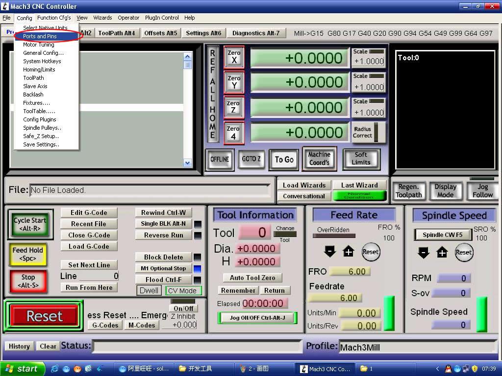
5 c. 8 WIRE STEPPER DIAGRAM 2 center wires of each coil connected (insulate connection) Remaining wires are connected to their corresponding terminal block location (i.e. A- wire is connected at A- location). If using 6 or 8 wire motors, connected using series wiring method, reduce labeled amperage rating by 50% (i.e. a motor rated at 4 amps should thus be considered now rated at 2 amps). 6. How to use MACH software? Pic.1 5

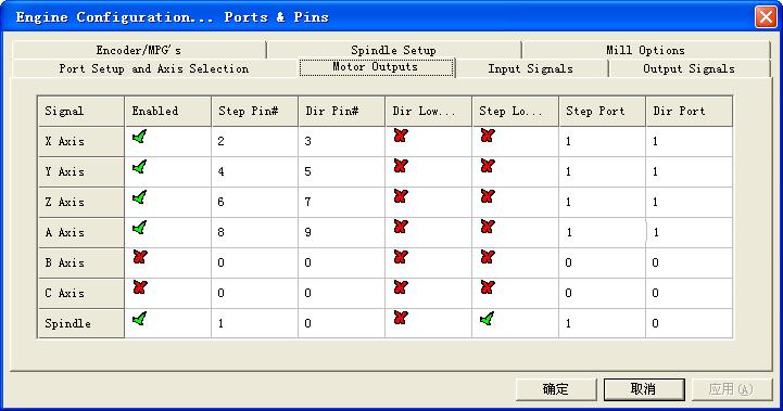
6 Pic.2 Pic.3 6

7 Pic.4 Pic.5 7

8 Pic.6 Pic.7 Pic.8 8

 Pic.")
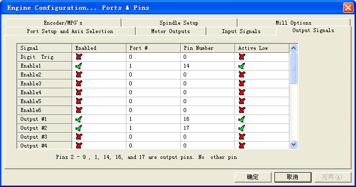
9 (Please note: some of computer has opposite "Active low" and "Active high", if it is with your computer, please change above three "Active Low" to "Active High".) Pic.9 Pic.10 9
10 Pic.11 Pic.12 10
1. Key Features. 2. Photo of 4-AXIS CNC Board
 This document describes the basic functionality and the electrical specifications of StepperOnline s Four Axis TB6600 CNC Driver Board. 1. Key Features Supports MACH3, KCAM4, EMC2 etc Can drive four channels
4-Axis TB6560 CNC Driver Board Users Manual. 1.1 Scope General Description Photo of 4-AXIS CNC Board Key Features...
 Content 4-Axis TB6560 CNC Driver Board Users Manual 1. General Information... 2 1.1 Scope... 2 1.2 General Description... 2 2. Descriptions of 4-AXIS CNC Board... 2 2.1 Photo of 4-AXIS CNC Board... 2 2.2
User's Manual. For ST-6560V3. Version All Rights Reserved
 User's Manual For ST-6560V3 Version 2.0 2016.08.25 All Rights Reserved 1. Key Features Toshiba TB6560AHQ chip - High power, maximum current 3.5A Resolution 1, 1/2, 1/8, 1/16 micro stepping output Working
Three Axis CNC Driver Users Manual
 Three Axis CNC Driver Users Manual Revision 1.2 June 14. 2007 1 Content 1. GENERAL INFORMATION... 3 1.1. Scope... 3 1.2. General Description... 3 1.3. Features... 3 2. Descriptions of 3-AXIS CNC Board...
TB6560 mach3 cnc Stepper Motor Controller operation instruction
 TB6560 mach3 cnc Stepper Motor Controller operation instruction CONTENT Ⅰ FEATURES OF TB6560...3 Ⅱ APPLICATIONS:...3 Ⅲ ELECTRICAL DRAWING...4 V DEFINITION ON PINS OF PARALLEL PORT...5 VI.ADJUSTING CURRENT
CNCMARKETİM. TB6560HQT4-v3 4 AXIS DRIVER USER MANUAL
 TB6560HQT4-v3 4 AXIS DRIVER USER MANUAL 1 Catalogue... 1 1. Overview...Hata! Yer işareti tanımlanmamış. 2. TB6560AHQ advantag... 2 2.1 At low speed operation System Advantages... 3 2.2 In high-speed operation
Manual. Model#-DB25M-3R6A. 6 Axis CNC Interface Breakout Board. Lastest update : Feb Store this manual away for further reference.
 Manual 6 Axis CNC Interface Breakout Board Model#-DB25M-3R6A Lastest update : Feb 2016 Read this manual carefully before making connections to the board. Store this manual away for further reference. Safety
Preliminary Datasheet MX Axis Stepper Drive with Breakout Board & I/O s. Preliminary V1.0
 Preliminary Datasheet MX4660 4-Axis Stepper Drive with Breakout Board & I/O s Preliminary V1.0 Features Power up to 4 stepper motors of NEMA 17, 23, 24, or 34 Sophisticated stepper motor control based
TB6560HQT4-v3 4 AXIS DRIVER USER MANUAL
 TB6560HQT4-v3 4 AXIS DRIVER USER MANUAL Catalogue...1 1. Overview... Error! Marcador no definido. 2. TB6560AHQ advantag...2 2.1 At low speed operation System Advantages...3 2.2 In high-speed operation
TB6560 3axis mach3 cnc Stepper Motor Controller operation instruction
 TB6560 3axis mach3 cnc Stepper Motor Controller operation instruction 1 Content TB6560 3axis mach3 cnc Stepper Motor Controller operation instruction...1 I. features of TB6560...3 Ⅱ Applications:...3 Ⅲ
Hardware Installation Manual MX Axis Stepper Drive with Breakout Board & I/O s
 Hardware Installation Manual MX3660 3-Axis Stepper Drive with Breakout Board & I/O s Version 1.0 11 / 2013 Hardware Manual for MX3660 3-Axis Stepper Drive with Breakout Board & I/O s ii Notice Read this
USER S MANUAL. CNC Servo Stepper Motor Control Box CH4EV12-1 Rev. 1
 USER S MANUAL CNC Servo Stepper Motor Control Box CH4EV12-1 Rev. 1 January, 2013 i USER'S MANUAL TABLE OF CONTENTS Page # Contents 1.0 FEATURES... 1 2.0 SPECIFICATIONS... 2 3.0 SYSTEM REQUIREMENTS... 2
TB6560HQ T3-V5 2.5A 3 AIXS DRIVER USER MANUAL WITH MANUL CONTROL TYPE
 TB6560HQ T3-V5 2.5A 3 AIXS DRIVER USER MANUAL WITH MANUL CTROL TYPE Catalogue TB6560HQ T3-V5...1 2.5A 3 AIXS DRIVER USER MANUAL WITH MANUL CTROL TYPE...1 1. Overview...2 2. TB6560AHQ advantage...3 2.1
Datasheet MX Axis Stepper Drive with Breakout Board & I/O s. Version1.0
 Datasheet MX3660 3-Axis Stepper Drive with Breakout Board & I/O s Version1.0 1. Features Power up to 3 stepper motors of NEMA 17, 23, 24, or 34 Sophisticated stepper motor control based on latest DSP technology
PP-BOB2-V1.0 PARALLEL PORT BREAKOUT BOARD
 PP-BOB2-v1 PARALLEL PORT BREAKOUT BOARD Document: Operation Manual Document #: T17 Document Rev: 2.0 Product: PP-BOB2-v1.0 Product Rev: 1.0 Created: March, 2013 Updated: Dec, 2014 THIS MANUAL CONTAINS
User Manual of 5Axis Breakout Board
 WWW.VALLDER.COM User Manual of 5Axis Breakout Board Safety Statement Vallder Ltd is not liable or responsible for any accidents, injuries, equipment damage, property damage, loss of money or loss of time
Manual 5 Axis CNC Interface Breakout Board Model#-DB25-1R5AM
 Manual 5 Axis CNC Interface Breakout Board Read this manual carefully before making connections to the board. Store this manual away for further reference. Safety Notes: The electronics of the control
USER S MANUAL. CNC Stepper Motor Control Box CS3EA4-1 Rev. 1
 USER S MANUAL CNC Stepper Motor Control Box CS3EA4-1 Rev. 1 April, 2012 USER'S MANUAL TABLE OF CONTENTS Page # Contents 1.0 FEATURES... 2 2.0 SPECIFICATIONS... 3 3.0 SYSTEM REQUIREMENTS... 3 4.0 WARNING...
CHANGZHOU WANTAI ELECTRICAL APPLIANCE CO., LTD. User Guide for 3 axis TB6560 driver board
 CHANGZHOU WANTAI ELECTRICAL APPLIANCE CO., LTD Product Features: User Guide for 3 axis TB6560 driver board Toshiba TB6560AHQ chip - High power, maximum 3.5A drive current chipset 1-1/16 microstep setting
3-Axis Stepper Drive Datasheet MX3660
 3-Axis Stepper Drive Datasheet MX3660 3-Axis Stepper Drive + Breakout Board, 20-60VDC, 6A Peak Version 0.0.2 http://www.leadshine.com Features Three individual stepper drive boards Suitable for NEMA17
MK5 5-Axis Controller
 MK5 5-Axis Controller Technical Reference Manual PCB Rev 1.0 2010 SOC Robotics, Inc. 1 Manual Rev 0.91 Introduction The MK5 is a 5-Axis breakout board that accepts the MM120, MM130, MM133 or MM220 stepper
HDBB Breakout board user s manual
 HDBB Breakout board user s manual The HDBB breakout board was designed to use with our Whale2(-T)*, Whale3, Mammut* and Dugong servo drives or with any other third party stepper or servo drives which using
CNC4PC. MULTIFUNCTION CNC BOARD Rev2
 CNC4PC Manual MULTIFUNCTION CNC BOARD Rev2 Overview This card has been designed to provide a flexible interface and functions to your computer projects, by using the parallel port control software. This
Datasheet MX Axis Stepper Drive with Breakout Board & I/O s. Version
 Datasheet MX4660 4-Axis Stepper Drive with Breakout Board & I/O s Version 1.0 http://www.leadshine.com http://www.leadshineusa.com 2014 Leadshine Technology Co., Ltd. Notice This document is not for use
PP-BOB2-V2.0 PARALLEL PORT BREAKOUT BOARD
 PP-BOB2-V2 PARALLEL PORT BREAKOUT BOARD Document: Operation Manual Document #: T18 Document Rev: 1.0 Product: PP-BOB2-V2.0 Product Rev: 1.0 Created: October, 2015 THIS MANUAL CONTAINS INFORMATION FOR INSTALLING
TB6600 Stepper Motor Driver
 TB6600 Stepper Motor Driver V1.0 07 2018 Open Source Mechatronics LTD 2018 Safety Statement The author of this document is not liable or responsible for any accidents, injuries, equipment damage, property
USER S MANUAL. C32- DUAL PORT MULTIFUNCTION CNC BOARD Rev. 4
 USER S MANUAL C32- DUAL PORT MULTIFUNCTION CNC BOARD Rev. 4 August, 2012 USER'S MANUAL TABLE OF CONTENTS Page # 1.0 FEATURES... 1-1 2.0 SPECIFICATIONS... 2-3 3.0 BOARD DESCRIPTION... 3-4 4.0 FUNCTIONAL
PLCIO2 Programmable Logic Controller Updated 3/26/10
 Overview: PLCIO2 Programmable Logic Controller Updated 3/26/10 PLCIO2 is a programmable logic controller which provides: 35 Inputs (bipolar, with a choice of 5 or 24) 39 Outputs (20SPST, 2 SPDT, 17 open
Hardware Installation Manual MX Axis Stepper Drive with Breakout Board & I/O s
 Hardware Installation Manual MX3660 3-Axis Stepper Drive with Breakout Board & I/O s Version 1.1 12 / 2013 http://www.leadshine.com http://www.leadshineusa.com 2013 Leadshine Technology Co., Ltd. Hardware
Datasheet MX Axis Stepper Drive with Breakout Board & I/O s. Version
 Datasheet MX3660 3-Axis Stepper Drive with Breakout Board & I/O s Version 1.1 http://www.leadshine.com http://www.leadshineusa.com 2013 Leadshine Technology Co., Ltd. Notice This manual is not for use
USER S MANUAL. C11- MULTIFUNTCION CNC BOARD Rev. 9.9
 USER S MANUAL C11- MULTIFUNTCION CNC BOARD Rev. 9.9 FEBRUARY, 2015 User s Manual Page i TABLE OF CONTENTS Page # 1. Overview... 1 2. Features... 1 3. Specifications... 3 4. BOARD DESCRIPTION... 4 5. Special
G540 4-AXIS DRIVE REV 4: MAY 28, 2010
 Thank you for choosing to purchase the G540 4-Axis Drive System. If you are dissatisfied with it for any reason at all within two weeks of its purchase date, you may return it for a full refund provided
USER S MANUAL. M16 POKEYS MOTION MOTHERBOARD Rev. 1.1 JUNE 2016.
 USER S MANUAL M16 POKEYS MOTION MOTHERBOARD Rev. 1.1 JUNE 2016. USER'S MANUAL TABLE OF CONTENTS Page # Contents 1.0 OVERVIEW... 1 2.0 FEATURES... 1 3.0 BOARD DESCRIPTION... 2 4.0 SPECIFICATIONS... 2 4.1
G540 User Manual. Date Modified: March 5, 2012 Page 1 of 10
 G540 User Manual Date Modified: March 5, 2012 Page 1 of 10 DIMENSIONS PHYSICAL AND ELECTRICAL RATINGS Minimum Maximum Units Supply Voltage 18 50 VDC Motor Current 0 3.5 A Power Dissipation 1 13 W Short
ACORN User Guide For Revision (Aka Acorn_rev3) Updated 1/23/17
 Updated 1/23/17") ACORN User Guide For Revision 171025 (Aka Acorn_rev3) Updated 1/23/17 Overview ACORN is technically a breakout board for the BeagleBone Green or BeagleBone Black embedded computer. The remainder of this
ACORN User Guide For Revision 171025 (Aka Acorn_rev3) Updated 1/23/17 Overview ACORN is technically a breakout board for the BeagleBone Green or BeagleBone Black embedded computer. The remainder of this
Hardware Installation Manual MX Axis Stepper Drive with Breakout Board & I/O s
 Hardware Installation Manual MX3660 3-Axis Stepper Drive with Breakout Board & I/O s Version 1.2 3 / 2015 http://www.leadshine.com http://www.leadshineusa.com 2015 Leadshine Technology Co., Ltd. Hardware
C35- QUICK SETUP BREAKOUT BOARD Rev. 1.1
 C35- QUICK SETUP BREAKOUT BOARD Rev. 1.1 User manual Rev. 1 1. Overview This card provides an easy way of interfacing your inputs and outputs from the parallel port. It provides terminals and RJ45 for
USER S MANUAL. C11S- MULTIFUNTCION CNC BOARD Rev. 1.2
 USER S MANUAL C11S- MULTIFUNTCION CNC BOARD Rev. 1.2 SEPTEMBER 2014 User s Manual Page i TABLE OF CONTENTS Page # 1. Overview... 1 2. Features... 1 3. Specifications... 3 4. BOARD DESCRIPTION... 4 5. Special
G540 MANUAL MULTIAXIS STEP MOTOR DRIVE
 G540 MANUAL MULTIAXIS STEP MOTOR DRIVE PRODUCT DIMENSIONS PHYSICAL AND ELECTRICAL RATINGS Minimum Maximum Units Supply Voltage 18 50 VDC Motor Current 0 3.5 A Power Dissipation 1 13 W Short Circuit Trip
IO3-R2 BREAKOUT BOARD
 IO3-R2 BREAKOUT BOARD DESCRIPTION Breakout board IO3-R2 (Revision R2) has digital buffer for STEP/DIR/ENA command signals and as such it is particularly suitable for the connection up to 4 microstep drives
Routout CNC 3 Axis Plug & Play Controller Data Sheet Version 1.1
 Routout CNC 3 Axis Plug & Play Controller Data Sheet Version 1.1 The Routout CNC 3 Axis stepper motor drive box has many uses including for CNC retrofitting / robot control or driving you own CNC machine.
User Guide for 4 axis TB6560 driver board. *Important Note*: Please strictly follow the setting photos for configuration
 User Guide for 4 axis TB6560 driver board Settings of MACH3 *Important Note*: Please strictly follow the setting photos for configuration in Mach3! Fig.1 Open MACH3 software, select mach3mill, and then
TurboTaig Instruction Manual
 TurboTaig Instruction Manual Version: 2.2 Peter Homann 20 View St Highett 3190 homann@smartchat.net.au http://people.smartchat.net.au/~homann 1 Table of Contents Table of Contents... 2 Introduction...
HY-TB3DV-S intelligent 3-axis drive board manual
 HY-TB3DV-S intelligent 3-axis drive board manual Thank you for choosing our company's products, the use of CNC products better and faster for you, please read this manuai Features: Features 1: integrated
Centroid ACORN CNC controller Specification and Use Guide Updated 8/3/17. Overview
 Centroid ACORN CNC controller Specification and Use Guide Updated 8//7 Overview ACORN is technically a CNC control breakout board for the BeagleBone Green or BeagleBone Black embedded computer the Beagle
EN006 - DigiSpeed Selection Chart
 - Selection Chart The range is designed to allow you to control the speed of your spindle motor from your CNC software. They do this by accepting a control signal from the CNC software and converting to
USER S MANUAL. C33 - MULTIFUNCTION ROUTER BOARD BOARD Rev. 4
 USER S MANUAL C33 - MULTIFUNCTION ROUTER BOARD BOARD Rev. 4 June 2013 USER'S MANUAL TABLE OF CONTENTS Page # Contents 1.0 OVERVIEW... 3 2.0 FEATURES... 3 3.0 SPECIFICATIONS... 4 4.0 FUNCTIONAL BLOCK DIAGRAMS...
DigiSpeed-SD DC-06. Isolated Control Voltage Generator User s Guide. DigiSpeed-SD PCB Ver:3.0 Mach3 Ver: 2.+ DigiSpeed-SD - Users Guide Page 1
 DigiSpeed-SD - Users Guide Page 1 Updated: 4 th May 2011 DigiSpeed-SD DC-06 Isolated Control Voltage Generator User s Guide DigiSpeed-SD PCB Ver:3.0 Mach3 Ver: 2.+ DigiSpeed-SD - Users Guide Page 2 Homann
C33- MULTIFUNCTION ROUTER BOARD Rev. 2
 C33- MULTIFUNCTION ROUTER BOARD Rev. 2 User manual Rev. 1 1. Overview This card provides an easy way of interfacing your router based spindle with your steeper motor driver board. This board includes a
USER S MANUAL VER.2. C76- MULTIFUNCTION CNC BOARD Rev. 1.4
 USER S MANUAL VER.2 C76- MULTIFUNCTION CNC BOARD Rev. 1.4 MARCH 2018 User s Manual Page i USER'S MANUAL TABLE OF CONTENTS Contents Page # 1.0 FEATURES... 1 2.0 I/O SPECIFICATIONS... 2 3.0 BOARD DESCRIPTION...
C45 - LIMIT AND HOME UNIVERSAL BOARD Rev. 1
 C45 - LIMIT AND HOME UNIVERSAL BOARD Rev. 1 User manual Rev. 1 1. Overview This card provides an easy means of connecting optical, mechanical and proximity sensor to operate as homing and limit switches
CNC4X35A 4 axis Stepper Motor Control Board
 CNC4X35A 4 axis Stepper Motor Control Board Just connect bipolar stepper motors, power and a parallel port signal source CNC4X35A 4 axis Stepper Motor Control Board Specs: Designed for easy construction/retrofit
User Manual. For 3rd Generation. 5 Axis Standard & Professional Breakout Board Set
 The 3 rd Generation 5 Axis Breakout Board Set User Manual For 3rd Generation 5 Axis Standard & Professional Breakout Board Set Attention: Please read the manual carefully before using the products! Email:
FARES Industrial Products Breakout Board FIPBOB4. General Description
 FARES Industrial Products General Description is a complete, buffered nonisolated parallel breakout board. It supports four output control signal groups to drive four axis CNC machine with extra two duplicated
HY-TB5 CNC Series Manual five axis
 HY-TB5 CNC Series Manual ------ five axis Thank you for choosing our products better and faster for you to use NC products, please read this manual, make sure the pump is started before the water-cooled
Profi4 Main Board Manual
 Profi4 Main Board Manual A. Scope of application It is used to run the signal processing of the host computer ( LPT port ), with MACH 3 CNC system software, and the peripheral machine dynamic electrical.
CNCtak.com CNCtak.com CNCtak.com
 1 User Guide for 4 axis TB6560 driver board เป นส นค าจากประเทศจ น ท ม จ ดเด นของ DRIVER BOARD ของ Toshiba TB6560AHQ chip ตามรายละเอ ยด Block Diagram Toshiba TB6560AHQ chip Product Features: 1.Toshiba
User Guide for 4 axis TB6560 driver board
 User Guide for 4 axis TB6560 driver board Product Features: Toshiba TB6560AHQ chip - High power, maximum 3.5A drive current chipset! 1-1/16 microstep setting - Higher accuracy and smoother operation than
User Guide for 3 axis TB6560 driver boar d
 User Guide for 3 axis TB6560 driver boar d Product Features: Toshiba TB6560AHQ chip - High power, maximum 3.5A drive current chipset! 1-1/16 microstep setting - Higher accuracy and smoother operation than
Novusun Controller Wiring and MACH3 Software Setup
 Novusun Controller Wiring and MACH3 Software Setup V1.0 01 2019 Open Source Mechatronics LTD 2019 Safety Statement The author of this document is not liable or responsible for any accidents, injuries,
C10- PARALLEL PORT INTERFACE CARD Rev. 8
 C10- PARALLEL PORT INTERFACE CARD Rev. 8 User manual Rev. 1 1. Overview This card provides an easy way of interfacing your inputs and outputs from you parallel port. It provides terminals for the connections
C23- DUAL PORT MULTIFUNCTION CNC BOARD Rev. 3.1
 C23- DUAL PORT MULTIFUNCTION CNC BOARD Rev. 3.1 User manual Rev. 2 1. Overview This card has been designed to provide a flexible interface and functions to computer CNC projects, by using the parallel
Thank you for choosing our company's products, the use of CNC products better and faster for you, please read this manual
 HY-TB3DV-HH(HL) 3-axis drive board manual Product Link: http://www.thanksbuyer.com/cnc-very-professiona l-3-axis-3-5a-tb6560-stepping-motor-driver-cont roller-lcd-display-cnc-router-24898 Thank you for
UNIPORT V2. Uniport V2
 UNIPORT V2 Uniport V2 USB powered Parallel port interconnection board with optical isolated inputs, buffered outputs, charge pump interlock and power relays Specification Full optical isolation of all
UCBB dual port breakout board user's manual
 UCBB dual port breakout board user's manual 1/14 Contents 1 Features 2 Dimensions 3 Connectors 3.1 Screw terminals 3.2 IDC ports 3.3 Powering 3.4 Outputs 3.5 Inputs 4 LED indicators 5 Example connections
C11G- MULTIFUNTCION CNC BOARD Rev. 8.2
 C11G- MULTIFUNTCION CNC BOARD Rev. 8.2 User manual Rev. 2 1. Overview This card has been designed to provide a flexible interface and functions to your computer projects, by using the parallel port control
Si 2035 Programmable Stepper Drive
 Si 23 Programmable Stepper Drive Description The Si23 is a programmable stepper drive/ indexer packaged in a rugged steel case. Integral heat sink, mounting brackets, switch covers and connectors are included
Galil Motion Control. EDD 3701x
 Galil Motion Control EDD 3701x Datasheet : Digital Drive 1-916-626-0101 Galil Motion Control 270 Technology Way, Rocklin, CA [Type here] [Type here] (US ONLY) 1-800-377-6329 [Type here] Product Description
C3 INDEX PULSE BOARD Rev. 6
 C3 INDEX PULSE BOARD Rev. 6 User manual Rev. 1 Fig. 1. C3 Index Pulse Board 1. Overview. This card provides easy way of capturing the pulse signal from photo-transistor and transmitting it to the parallel
User Manual For DM332T. 2-Phase Digital Stepper Drive. Designed by StepperOnline. Manufactured by Leadshine
 User Manual For DM332T 2-Phase Digital Stepper Drive Designed by StepperOnline Manufactured by Leadshine #7 Zhongke Road, Jiangning, Nanjing, China T: 0086-2587156578 Web site: www.omc-stepperonline.com
XS-3525/8S-3. Standard Pinout Information. Single Supply (v1s) XØ YØ ZØ
 XØ YØ ZØ") XS-3525/8S-3 Single Supply (v1s) Standard Pinout Information XØ YØ ZØ The 26 pin header is configured to allow easy connection via ribbon cable to an IDC DB-25 connector. This facilitates direct connection
XS-3525/8S-3 Single Supply (v1s) Standard Pinout Information XØ YØ ZØ The 26 pin header is configured to allow easy connection via ribbon cable to an IDC DB-25 connector. This facilitates direct connection
uservo box instruction manual
 Safety notes uservo box instruction manual Every machine controlled by computer (PC) can be really dangerous for human life and health. Comply with bolow rules and use Your common sense while working with
PLCADD1616 User Guide 3/29/10. Overview
 PLCADD1616 User Guide 3/29/10 Overview The PLCADD1616 is a PLC expansion board used to add digital inputs and outputs to a compatible host PLC. The PLCADD1616 has 16 relay outputs and 16 optically isolated
MP6500 Stepper Motor Driver, Digital Current Control
 This breakout board for the MPS MP6500 micro stepping bipolar stepper motor driver is Pololu s latest stepper motor driver. The module has a pinout and interface that are very similar to that of our popular
ACE-SDC-V3 Stepper Driver +Controller with USB 2.0 Communication
 ACE-SDC-V3 Stepper Driver +Controller with USB 2.0 Communication ACE-SDC-V3 Manual page 1 rev 1.00 COPYRIGHT 2008 ARCUS, ALL RIGHTS RESERVED First edition, April 2008 ARCUS TECHNOLOGY copyrights this document.
Thank you for choosing our products better and faster operational
 Aerospace TB3-axis drive board H-TB3DV-M Instructions Thank you for choosing our products better and faster operational numerical control for you, please read this manual Products Features 1 The maximum
Release Note. How to Use the OptoCon Connection Module. 1 Introduction. Option C Revision 4 Revised 8/13/98
 33 South La Patera Lane Santa Barbara, CA 93117-3214 ph (805) 681-3300 fax (805) 681-3311 tech@motioneng.com www.motioneng.com Release Note How to Use the OptoCon Connection Module Option C002-0007 Revision
CNC4PC. C11G - MULTIFUNCTION CNC BOARD Rev. 5.4
 CNC4PC Manual C11G - MULTIFUNCTION CNC BOARD Rev. 5.4 Overview This card has been designed to provide a flexible interface and functions to your computer projects, by using the parallel port control software.
MSD325 Microstepping Drive
 MSD325 Microstepping Drive Introduction MSD325 is a very small size microstepping drive based on most advanced technology in the world today. It is suitable for driving any 2-phase and 4-phase hybrid stepper
UNIPORT V3. C R H Electronics Design
 UNIPORT V3 V C R H Electronics Design Uniport V3 USB powered Parallel port interconnection board with optical isolated inputs, buffered outputs, charge pump interlock and power relays By C R Harding Specification
USER S MANUAL. C35S- QUICK SETUP BREAKOUT BOARD Rev. 1.3
 USER S MANUAL C35S- QUICK SETUP BREAKOUT BOARD Rev. 1.3 FEBRUARY, 2015 USER'S MANUAL TABLE OF CONTENTS Page # Contents 1.0 OVERVIEW... 1 2.0 FEATURES... 1 3.0 SPECIFICATIONS.... 2 4.0 BOARD DESCRIPTION...
Answers to Chapter 2 Review Questions. 2. To convert controller signals into external signals that are used to control the machine or process
 Answers to Chapter 2 Review Questions 1. To accept signals from the machine or process devices and to convert them into signals that can be used by the controller 2. To convert controller signals into
Manual of 2-phase hybrid stepper motor driver DQ542MA
 Manual of 2-phase hybrid stepper motor driver DQ542MA Introduction: DQ542MA is a type of two-phase hybrid stepping motor driver, the drive voltage of which is from 18VDC to 5VDC. It is designed for use
Breakoutboard for ESS Smoothstepper
 Breakoutboard for ESS Smoothstepper Operation Manual All rights to these operating instructions remain with cnc-technics. Texts, information and illustrations of these operating instructions may not be
SMD Series Integrated Stepper Driver and Motor Revision 1.3
 The AMCI Integrated Stepper Motor and Microstepping Drive Combination represents the future of Stepper Motor Control applications. The SMD is a self-contained stepper motor and driver package, capable
Hardware Manual 1240i-485
 Hardware Manual -485 Intelligent Step Motor Driver with Multi-drop RS-485 Interface 920-0033 A 7/6/2010 motors drives controls -2- Table of Contents Introduction...4 Features...4 Block Diagram...4 Getting
DEV16T. LCD Daughter board
 LCD Daughter board Table of Contents 1 Introduction...2 2 Features...3 3 Expansion Connectors...4 3.1 Daughter Board Connectors...4 4 LCD Display...5 5 Input Buttons S1 to S4...5 6 Buzzer...5 7 Connector
ADVANCED MICRO SYSTEMS
 Overview... 3 Included in the Box:... 3 Pinout... 4 Installation... 5 Power Supply... 6 Stepping Motors... 7 DIP Switch (JP1) Location... 8 Setting the Output Current (JP1)... 8 Microstep Resolution (JP1)...
USER S MANUAL. E6 POKEYS MOTION CONTROLLER CNC INTERFACE DB25 Rev.1
 USER S MANUAL E6 POKEYS MOTION CONTROLLER CNC INTERFACE DB25 Rev.1 April, 2013 USER'S MANUAL TABLE OF CONTENTS Page # Contents 1.0 FEATURES... 2 2.0 SPECIFICATIONS... 3 3.0 SYSTEM REQUIREMENTS... 3 4.0
USER S MANUAL VER.1. C11G- MULTIFUNTCION CNC BOARD Rev. 9
 USER S MANUAL VER.1 C11G- MULTIFUNTCION CNC BOARD Rev. 9 MARCH, 2017 User s Manual Page i USER'S MANUAL TABLE OF CONTENTS Contents Page # 1.0 OVERVIEW... 1 2.0 FEATURES... 1 3.0 SPECIFICATIONS... 2 4.0
GUIDE TO SP STARTER SHIELD (V3.0)
") OVERVIEW: The SP Starter shield provides a complete learning platform for beginners and newbies. The board is equipped with loads of sensors and components like relays, user button, LED, IR Remote and
OVERVIEW: The SP Starter shield provides a complete learning platform for beginners and newbies. The board is equipped with loads of sensors and components like relays, user button, LED, IR Remote and
FAN CONTROLLER BRIEF DESCRIPTION
 TINY Drive TDS-2/4 FAN CONTROLLER BRIEF DESCRIPTION Description TINY Drive TDS 2/4 is an universal microprocessor controller designed to control and diagnose several types of DC fans. Controller allows
- Electronic Limit Switches - Very Accurate - Easy to use - Robust - Dependable - High Resolution - Non Contact Measurement - Wide Temp.
 1-30-2018 EPS 02 Operating Instructions RACO Electronic Position Sensor - Electronic Limit Switches - Very Accurate - Easy to use - Robust - Dependable - High Resolution - Non Contact Measurement - Wide
AN004 Using the PMDX-126 s Error Input and Restart Output with Geckodrive Servo Drivers and Mach3 CNC Software
 1.0 Overview This application note describes how to connect the to the Geckodrive G320//G340 step servo driver s ERR/RST terminal to allow the to detect a Geckodrive error (fault) state and to reset the
CU2/CUF Connector Wiring Diagrams
 Page of CU/CUF CONNECTOR WIRING DIAGRAMS CU/CUF Connector Wiring Diagrams Version: 0-0-0 This manual supports: CUFHP - CUHP - CUXJ - CUXJ00 Index CU/CUF connectors... Fuses... I/O connector... Encoder
Mk3DRV controller user manual 2018/01/09
 Mk3DRV controller user manual 2018/01/09 Disclaimer CONTROLLER AND CONTROLLER SOFTWARE ARE PROVIDED TO YOU "AS IS," WITHOUT WARRANTY. THERE IS NO WARRANTY FOR THE CONTROLLER AND CONTROLLER SOFTWARE, EITHER
Apollo I Breakout Board User s Manual
 MACHMOTION Apollo I Breakout Board User s Manual 1/14/2012 Everything you need to know to set up and use your Apollo I Breakout Board. MachMotion Version 1.0.1 2 P a g e M a c h M o t i o n Copyright 2012,
MSD980 Microstepping Drive
 MSD980 Microstepping Drive Introduction MSD980 is a high-performance microstepping drive based on most advanced technology in the world today. It is suitable for driving any 2-phase and 4-phase hybrid
PMDX-424 SmartBOB-IsoUSB For use with Mach4
 PMDX-424 SmartBOB-IsoUSB For use with Mach4 Quick Start Guide Document Revision: 0.6 Date: 8 April 2016 Circuit Board Revisions: PCB-525A and PCB-525B PMDX Web: http://www.pmdx.com 9704-D Gunston Cove
C10S- PARALLEL PORT INTERFACE CARD Rev. 1.4
 USER S MANUAL VER.1 C10S- PARALLEL PORT INTERFACE CARD Rev. 1.4 SEPTEMBER, 2016 User s Manual Ver.1 Page i USER'S MANUAL TABLE OF CONTENTS Page # 1. OVERVIEW... 1 2. FEATURES... 1 3. SPECIFICATIONS...