VF66 TOYO INTELLIGENT INVERTER. PBUS66-Z Communication Protocol Manual
|
|
|
- Branden West
- 5 years ago
- Views:
Transcription

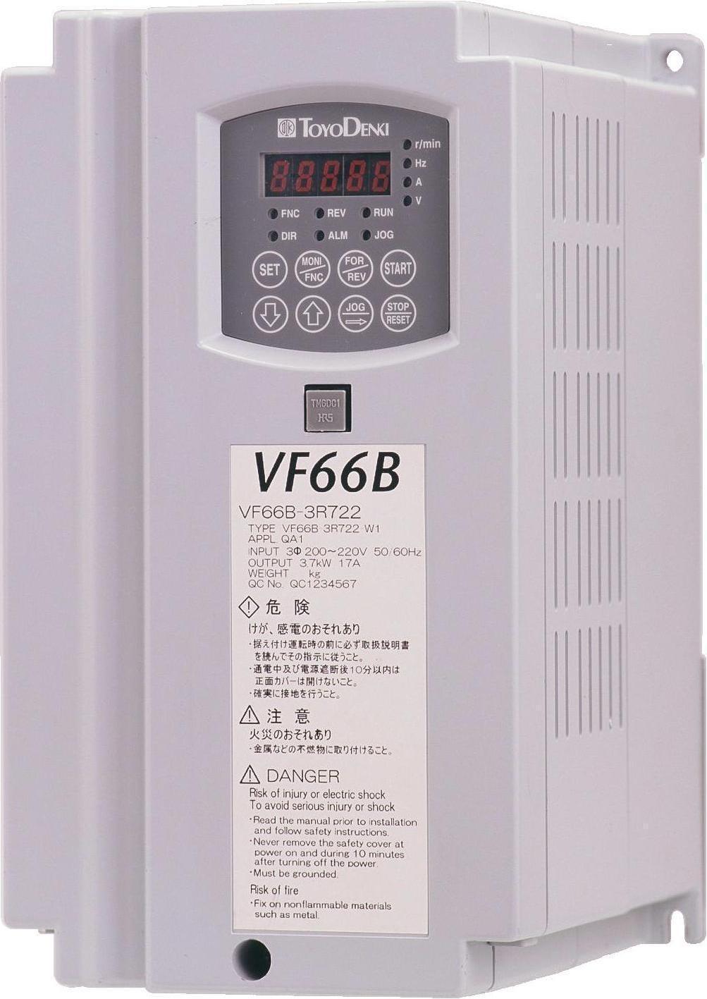


1 VF66 TOYO INTELLIGENT INVERTER PBUS66-Z Communication Protocol Manual
2 Foreword We thank you for choosing a Toyo inverter product. This instruction manual contains information regarding the PBUS66-Z Optional Circuit Board communication protocols for the VF66B Inverter. For correct communication protocol use, please carefully read this instruction manual prior to using the PBUS66-Z. This instruction manual explains the workings of the PBUS66-Z PROFIBUS-DP communication function. For more information about the PBUS66-Z terminal block functions, wiring procedures, switch configuration and setting up the VF66B inverter, please refer to the PBUS66-Z Operating Manual. In order to accommodate the many special functions to a wide variety of applications in addition to the basic VF66B inverter functions, please thoroughly read the VF66B inverter manual as well as any other applicable specialized instruction manuals.
3 Safety Precautions Read Prior To Use Before installing, operating, maintaining and inspecting the PBUS66-Z unit, carefully read this instruction manual and all other appendices and handle the unit as instructed. Before operation, be sure to become acquainted with all the component s details, safety information and precautions. For safe operation, be sure to also thoroughly read the VF66B Inverter operating manual. In this instruction manual, the safety instructions are classified into two levels: DANGER and CAUTION. DANGER CAUTION Indicates a hazardous situation which may result in death or serious injury if the unit is handled improperly. Indicates a hazardous situation which may result in moderate or minor injury or property damage if the unit is handled improperly. However, depending on circumstances, such a situation may lead to serious consequences. These precautions indicate important instructions and must be followed without fail. CAUTION [Installation] Do not use equipment if you discover damage or deformation during unpacking. Doing so may cause equipment failure or malfunction. Do not place any flammable materials near the device. Doing so may cause a fire. Do not allow the unit to drop, fall over or sustain severe impacts. Doing so may cause equipment failure or damage. Do not install or operate the optional circuit board if it is damaged or has missing parts. Doing so may lead to personal injury. DANGER [Wiring] Before wiring up the unit, make sure the power is OFF. Failure to do so may cause an electric shock or fire. Wait more than 10 minutes after turning the power OFF before opening the unit case lid. Make sure that the unit is correctly earthed. Failure to do so may cause an electric shock or fire. Wiring must only be performed by a skilled electrical technician. Failure to do so may cause an electric shock or fire. Always wire up the unit after it has been installed. Failure to do so may cause an electric shock or fire.
4 CAUTION [Wiring] Make sure that communication cables and connectors are properly installed and locked in place. Failure to do so may cause equipment failure or malfunction. DANGER [Operation] Turn the power ON only after fitting the inverter front cover. Do not remove the cover while the power is ON. Doing so may cause an electric shock. Do not operate any switch with wet hands. Doing so may cause an electric shock. Do not touch the inverter terminal while the power is ON, even if it is not in a state of operation. Doing so may cause an electric shock. If the alarm is reset while an operation signal remains input, the unit can suddenly restart. Confirm that the operation signal is off before resetting the alarm. Failure to do so may lead to personal injury. The inverter can be configured to operate at a wide range of speeds. Operate the inverter only after thoroughly checking the allowable range of the motor and machine. Failure to do so may cause personal injury, equipment failure or damage. CAUTION [Operation] The inverter radiating fins and radiating resistors can be hot and should never be touched. Failure to follow this warning may cause burns. DANGER [Maintenance, Inspection and Parts Replacement] Always turn the power OFF before inspecting the unit. Failure to do so may cause an electric shock, personal injury or fire. Unauthorized persons must not perform maintenance, inspection or parts replacement. Use insulated tools for maintenance and inspection. Failure to do so may cause electric shock or personal injury. CAUTION [Other] Never modify the unit. Doing so may cause electric shock or personal injury. CAUTION [General Precautions] Some illustrations contained within this manual show the unit with its covers or safety shields removed in order to illustrate the details. Before operation, reinstall all covers and shields to their original positions as specified, and operate in accordance with the guidelines contained within this manual. These safety precautions, and specifications stated in each manual are subject to change without notice.
5 Table of Read Prior To Use... 3 Safety Precautions... 3 Chapter 1 Outline of Functions... 6 Chapter 2 Basic Specifications PROFIBUS-DP Communication Terminal Specifications PROFIBUS-DP Communication Specifications Communication Modes Other... 8 Chapter 3 Communication Function Explanation Setting of Parameters PROFIDRIVE Compatible Mode Mode 0 PPO Type 1 Communication Frame Mode 0 PPO Type 2 Communication Frame Mode 0 PPO Type 3 Communication Frame Mode 0 PPO Type 4 Communication Frame Mode 0 PPO Type 5 Communication Frame Original Mode Mode 1 Communication Frame Control/Status Word Explanation of Control Word (Master Slave) Explanation of Status Word (Slave Master) PROFIDRIVE (Control Word) Operating Procedure Operation Command / Status Flag / Fault Flag / Multifunction Input and Output Master Output (Input to Inverter) Master Input (Output From Inverter) Diagnosis Data Explanation of PKE Part (Inverter internal data access) Explanation of Each Word Data Monitor Data Reading Trace-Back Data Reading Protection History Reading Configuration Data Reading Configuration Data Rewriting... 44
6 Chapter 1 Outline of Functions The PBUS66-Z Optional Circuit Board has been designed to connect to the VF66B Inverter s internal VFC66-Z circuit board connector. In addition to the PROFIBUS-DP slave station communication function, the PBU66-Z is also equipped with analogue input/output, multifunction input and PG input/output functions. Through PROFIBUS-DP communication, the PBUS66-Z can input operation, speed and torque commands to the VF66B Inverter as well as monitor factors such as operating conditions, protection conditions, current and voltage. It can also read and rewrite the inverter configuration data as well as read the trace-back data, protection history and monitor data. Furthermore, it can be used as the input/output signal of the VF66B Inverter built-in PLC function. For information about the built-in PLC function, please refer to the VF66B PCTool manual. In order to reduce environmental impact, the PBUS66-Z has been designed to contain levels of lead, mercury, cadmium, hexavalent chromium, PBB and PBDE that conform to the RoHS directive issued by the EU. CAUTION [Safety Precautions] Be sure to thoroughly read the operating manual prior to use and always operate in a correct manner. The inverter and optional circuit board made by our company have not been designed or manufactured to be used with equipment or part of systems that are used to maintain or affect human life. If you intend to use the product described in this manual for specific applications such as passenger transportation, medical, aerospace, nuclear control, submarine relay equipment or other special uses, please contact us. This product is manufactured under strict quality control. However, when this inverter or optional circuit board is used in critical systems where a failure may affect the lives of humans or cause great loss, safety measures must be taken in order to prevent serious accidents. If you wish to use this inverter with loads other than three-phase alternating current motors, please contact us. This product requires electrical work. This must only be performed by a skilled electrical technician.
7 PBUS66-Z Terminal Block TB1 Chapter 2 Basic Specifications 2.1 PROFIBUS-DP Communication Terminal Specifications Terminal Name Table 2.1 PROFIBUS-DP Communication Terminal Specifications Application Description N. A - A-line (RxD/TxD-N) connection terminal. Communication Signal Terminal P. B - B-line (RxD/TxD-P) connection terminal. RTS P5 G3 E Request To Send +5V Power Supply Terminal Communication Earth Terminal Protective Earth Terminal - Used when connecting to equipment where the communication direction must be clearly defined. Output is Hi (+5V) during PBUS66-Z data transmission and Low (0V) for all other times. - Outputs a +5V DC voltage. - Signal line data earth terminal. - Connects to the connection-cable shielded wire. 2.2 PROFIBUS-DP Communication Specifications Table 2.2 PROFIBUS-DP Communication Specifications Communication Protocol International Standard Physical Layer Connection Type Transmission Speed and Transmission Distance Transmission Method Synchronization Method Communication Control Method Error Check Method Data Format Connection, Wiring Method Connection Cable Number Of Connection Stations Station Number Setting Transmission Speed GSD File PROFIBUS-DP compliant EN (IEC61158) RS-485 compliant Bus type 9.6K, 19.2K, 45.45K, 93.75Kbps Less than 1,200m 187.5Kbps Less than 1,000m 500Kbps Less than 400m 1.5Mbps Less than 200m 3M, 6M, 12Mbps Less than 100m Half Duplex Start-Stop Synchronization Polling/Selecting Method FCS (Frame Check Sequence) Start bit (1 bit) Data (8 bits) Parity check (1 bit, even number) Stop bit length (1 bit) Terminal block Two-wire system Shielded twisted-pair cable (PROFIBUS-DP dedicated cable). A maximum of 32 stations, combining master and slaves (without repeater) A maximum of 126 stations (with repeater) Configuration via the VF66B inverter internal console Automatic configuration by the transmission data received from the master TOYO0BE7. GSD
8 2.3 Communication Modes The PBUS66-Z allows communication mode selection of either the PROFIDRIVE Profile compliant PROFIDRIVE Compatible Mode or our company s specially developed Original Mode. For more information about communication mode configuration (J-08) and communication frames, please refer to Chapter Other Mode 0.PROFIDRIVE Compatible Mode Mode 1.Original Mode Mode 2.Special Mode (Disabled) PROFIDRIVE Profile Version Used PROFIDRIVE Profile, Order-No: Profile Number: 3 Version: 2 For more information about specifications of other components such as terminal blocks, please refer to the PBUS66-Z Operating Manual. DANGER [Wiring] Confirm that the power is OFF before performing any wiring. Failure to do so may cause an electric shock or fire. CAUTION [Wiring] Never connect the G or G2 terminal to earth. Doing so may cause equipment failure or damage. Do not connect or allow contact between the PS and G terminals. Doing so may cause equipment failure or damage.
9 Chapter 3 Communication Function Explanation 3.1 Setting of Parameters Through PROFIBUS-DP communication, the PBUS66-Z can input operation and speed commands and torque commands into the VF66B Inverter as well as monitor factors such as operating conditions, protection conditions, current and voltage. It can also read and rewrite the inverter configuration data as well as read the trace-back data, protection history and monitor data. Furthermore, it can be used as the input/output signal of the VF66B Inverter built-in PLC function. For information about the built-in PLC function, please refer to the VF66 PCTool manual. For more information about procedures to connect PROFIBUS-DP transmission lines to the PBUS66-Z terminal block, please refer to the PBUS66-Z Operating Manual. In order to communicate with the PROFIBUS master station, the VF66B inverter configuration parameters shown in the following table must be set. Please also refer to the PBUS66-Z Operating Manual, the VF66B inverter manual and the applicable master station manual. Console Display J-00 J-03 J-08 Digital communication option selection PBUS66-Z slave station address PBUS66-Z communication mode selection Table 3.1 PROFIBUS-DP Communication Settings Configuration Range (Item Selection) 0: Communication option not used 4: PBUS66-Z used 1-3, 5-7: Set when using other options Default Setting Rewriting During Operation 0 0 to : Mode 0, PROFIDRIVE compatible mode 1: Mode 1, Original mode 2: Mode 2, Special mode (disabled) 0 * Turn the inverter power OFF and then ON again after any of these settings are changed.
10 With the PBUS66-Z, the data configuration of the communication frames handled by PROFIBUS-DP communication varies depending on whether the built-in PLC function is used or not. Use or nonuse of the built-in PLC function can be set with the VF66B inverter configuration parameters (i-area) as shown in the following table. For more information, please refer to the VF66B inverter manual. For information about the built-in PLC function, please refer to the VF66 PCTool manual. Console Display i-00 i-01 PLCL function usage selection PLCH function usage selection Table 3.2 Built-in PLC Function Usage Selection Item Selection OFF (Disabled) ON (Enabled) 0: OFF (Disabled) 1: PLCH ON 2: LCH ON (Speed command input is set as PLCH output) Default Setting OFF Rewriting During Operation 0 To enable various commands communicated to the VF66B inverter, the inverter configuration parameters shown in the following table must be correctly set. To enable the operation control signal, forward operation terminal ST-F on the VFC66-Z terminal block TB1 of the VF66B inverter control circuit board must be turned ON. For more information, please refer to the VF66B inverter manual. Console Display b-09 b-10 b-11 b-12 i-07 i-08 J-14 Table 3.3 Input Position Selection Settings For Various Commands Command input position selection for interlocking Rotation speed command input position selection (*1) Operation command input position selection Jog command input position selection Operation mode selection (*2) Torque command input position selection (*2) Time/date data selection from communication Configuration Range (Item Selection) 0: Terminal block 1: Console (SET66-Z) 2: Digital communication option 0: Interlocking 1: Analog Input (1) [Terminal block] (AIN1) 2: Console (SET66-Z) 3: Digital communication option 4: Analog Input (2) [IO66-Z option or digital communication optional terminal block] (AIN2) 5: (For external optional expansions) 6: Analog Input (3) [IO66-Z optional terminal block] (AIN3) 7: Built-in PLC 0: Interlocking 1: Terminal block 2: Console (SET66-Z) 3: Digital communication option 0: Interlocking 1: Terminal block 2: Console (SET66-Z) 3: Digital communication option 0: Speed control (ASR) mode 1: Torque command minus (-) direction priority 2: Torque command plus (+) direction priority 3: Torque control (ATR) mode 4: Speed/torque control contact switching 0: Analog Input (1) [VFC66-Z terminal block] (AIN1) 1: Analog Input (2) [IO66-Z, digital communication optional terminal block] (AIN2) 2: Digital communication option 3: Built-in PLC output 0: Without time/date data 1: With time/date data Default Setting (*1) If the inverter is in V/f mode, this becomes Frequency command input position selection. (*2) If the inverter is in V/f mode, this is disabled. Rewriting During Operation
11 To enable multifunction input by communication, the PLCL function must be disabled and the multifunction input position selection parameter must be set to the digital communication option as shown in the following table. For more information, please refer to the VF66B inverter manual. Console Display c-00 Multifunction input position selection Table 3.4 Multifunction Input Position Selection Item Selection 0: Terminal block (Multifunction input via terminal block) 1: Digital communication option (Multifunction input via communication option) Default Setting Rewriting During Operation 0
12 3.2 PROFIDRIVE Compatible Mode PROFIDRIVE compatible mode conforms to PPO-Type 1 to 5 defined in the PROFIDRIVE Profile. An outline of each type is provided as follows. In this mode, each master input and output data has the same number of words. P K W P Z D PKE IND PWE1 PWE2 PZD1 STW ZSW PZD2 HSW HIW PZD3 PZD4 PZD5 PZD6 PZD7 PZD8 PZD9 PZD10 PPO-Type1 4WORD + 2WORD = 6WORD PPO-Type2 4WORD + 6WORD = 10WORD PPO-Type3 2WORD PPO-Type4 6WORD PPO-Type5 4WORD + 10WORD = 14WORD Figure 3.1 PPO Type Configurations PPO Type settings are determined from configuration data sent from the master. With the PBUS66-Z, in order to change a pre-set PPO Type, it is necessary to turn off the inverter power supply, turn the power back on, and set up with new configuration data sent from the master. In the above frame configuration table, PKW is used for reading and writing of the inverter internal parameter data. The data length for the PKW part is fixed at 4 words. (For more information, please refer to Section 3.7.) Since PPO Type 3 and 4 do not have a PKW part, reading and writing of inverter internal parameter data cannot be performed using communication. The PZD part consists of communication data cyclically exchanged between the master and slave. PZD1 and 2 carry special meanings. PZD1 is bit data called control word or status word. PZD2 indicates a set value or actual value. For example, with the above mentioned PPO Type 1, PKW = 4 words + PZD = 2 words for a total of 6 words are exchanged between the master and slave.
13 PKE PPO-Type1 6WORD Master Output Master Input Master Output Master Input P K W (ParameterID/Value) IND PWE1 PWE2 P Z D (Process data) PZD1 STW ZSW ID+PNU Sub index Not used Control word Speed ID+PNU Sub index PPO-Type2 10WORD Master Output Master Input ID+PNU Sub index Not used Control word Speed ID+PNU Sub index Parameter value Parameter value Status word ID+PNU Sub index Not used Control word Speed ID+PNU Sub index PPO-Type3 2WORD Master Output Master Input PPO-Type4 6WORD Master Output Master Input PPO-Type5 14WORD Not used Not used Not used Parameter value Parameter value Parameter value Parameter value Status word Status word PZD2 HSW HIW Command (Input Register 1) Motor Speed (Output Register 1) Command (Input Register 1) Motor Speed (Output Register 1) Control word Speed Command (Input Register 1) Status word Motor Speed (Output Register 1) Control word Speed Command (Input Register 1) Status word Motor Speed (Output Register 1) Command (Input Register 1) Motor Speed (Output Register 1) PZD3 Torque Command (Input Register 2) ARC Output (Output Register 2) Torque Command (Input Register 2) ARC Output (Output Register 2) Torque Command (Input Register 2) ARC Output (Output Register 2) PZD4 Month, Day (Input Register 3) Actual Current (Output Register 3) Month, Day (Input Register 3) Actual Current (Output Register 3) Month, Day (Input Register 3) Actual Current (Output Register 3) PZD5 Hour, Minute (Input Register 4) Torque Command Value (Output Register 4) Hour, Minute (Input Register 4) Torque Command Value (Output Register 4) Hour, Minute (Input Register 4) Torque Command Value (Output Register 4) PZD6 PZD7 PZD8 PZD9 PZD10 Not Used (Input Register 5) DC Voltage (Output Register 5) Not Used (Input Register 5) DC Voltage (Output Register 5) Not Used (Input Register 5) DC Voltage (Output Register 5) Not Used (Input Register 6) Status Flag Not Used (Input Register 7) Fault Flag 1 Control, Multifunction Input 1 Fault Flag 2 Multifunction Input 2 Multifunction Output Items contained within parentheses are used when the built-in PLC function is enabled. Figure 3.2 Each PPO Type Communication Frame (Mode 0)
14 3.2.1 Mode 0 PPO Type 1 Communication Frame PPO Type1 configuration data: 0xF3, 0xF1 (4 + 2 words IN/OUT) Built-in PLC Function Not Used Master Transmitting Data (Master Slave) 6 words (PPO-Type 1, PLCH: OFF) +0 PKE (L) +1 PKE (H) +2 IND (L) +3 IND (H) The leading 4WORD is the PKW part. +4 PWE1 (L) It is used for reading and writing the inverter internal parameters. +5 PWE1 (H) This is further explained in Section PWE2 (L) +7 PWE2 (H) +8 Control Word (L) More information can be found in Section Control Word (H) +10 Speed Command (L) 20000/Maximum rotation speed (A-00) +11 Speed Command (H) (Frequency command when in V/f mode) Master Receiving Data (Slave Master) 6 words (PPO-Type 1, PLCH: OFF) +0 PKE (L) +1 PKE (H) +2 IND (L) +3 IND (H) The leading 4WORD is the PKW part. +4 PWE1 (L) It is used for reading and writing the inverter internal parameters. +5 PWE1 (H) This is further explained in Section PWE2 (L) +7 PWE2 (H) +8 Status Word (L) More information can be found in Section Status Word (H) +10 Motor Speed (L) 20000/Maximum rotation speed (A-00) +11 Motor Speed (H) (Frequency command when in V/f mode)
15 3.2.1 Mode 0 PPO Type 1 Communication Frame (Continued) Built-in PLC Function Used Master Transmitting Data (Master Slave) 6 words (PPO-Type 1, PLCH: ON) +0 PKE (L) +1 PKE (H) +2 IND (L) +3 IND (H) The leading 4WORD is the PKW part. +4 PWE1 (L) It is used for reading and writing the inverter internal parameters. +5 PWE1 (H) This is further explained in Section PWE2 (L) +7 PWE2 (H) +8 Control Word (L) More information can be found in Section Control Word (H) +10 i00010 (L) Communication input register 1 * +11 i00010 (H) * CAUTION: There may be cases where i00010 is cleared to zero by the control word. For more information, please refer to the CAUTION notes on Page 31. Master Receiving Data (Slave Master) 6 words (PPO-Type 1, PLCH: ON) +0 PKE (L) +1 PKE (H) +2 IND (L) +3 IND (H) The leading 4WORD is the PKW part. +4 PWE1 (L) It is used for reading and writing the inverter internal parameters. +5 PWE1 (H) This is further explained in Section PWE2 (L) +7 PWE2 (H) +8 Status Word (L) More information can be found in Section Status Word (H) +10 o00010 (L) Communication output register o00010 (H)
16 3.2.2 Mode 0 PPO Type 2 Communication Frame PPO Type2 configuration data: 0xF3, 0xF5 (4 + 6 words IN/OUT) Built-in PLC Function Not Used Master Transmitting Data (Master Slave) 10 words Master Receiving Data (Slave Master) 10 words (PPO-Type 2, PLCH: OFF) +0 PKE (L) +1 PKE (H) +2 IND (L) +3 IND (H) The leading 4 words are the PKW part. +4 PWE1 (L) It is used for reading and writing the inverter internal parameters. +5 PWE1 (H) This is further explained in Section PWE2 (L) +7 PWE2 (H) +8 Control Word (L) More information can be found in Section Control Word (H) +10 Speed Command (L) 20000/Maximum rotation speed (A-00) +11 Speed Command (H) (Frequency command when in V/f mode) +12 Torque Command (L) 5000/Rated torque +13 Torque Command (H) +14 Month Day (L) Day setting 1-31 [Day] +15 Month Day (H) Month setting 1-12 [Month] +16 Hour - Minute (L) Minute setting 0-59 [Minute] +17 Hour - Minute (H) Hour setting 0-23 [Hour] +18 Not used +19 (PPO-Type 2, PLCH: OFF) +0 PKE (L) +1 PKE (H) +2 IND (L) +3 IND (H) The leading 4 words are the PKW part. +4 PWE1 (L) It is used for reading and writing the inverter internal parameters. +5 PWE1 (H) This is further explained in Section PWE2 (L) +7 PWE2 (H) +8 Status Word (L) More information can be found in Section Status Word (H) +10 Motor Speed (L) 20000/Maximum rotation speed (A-00) +11 Motor Speed (H) (Output Frequency when in V/f mode) +12 ARC Output (L) 20000/Maximum rotation speed (A-00) +13 ARC Output (H) +14 Actual Current Value (L) 10000/100% +15 Actual Current Value (H) +16 Torque Command Value 5000/Rated value (L) +17 Torque Command Value (Operation torque when in V/f mode) (H) +18 DC Voltage (L) 200V system: Vdc 10, 400V system: Vdc DC Voltage (H) * The 100% value is the value of the inverter rated current (A) multiplied by the gain shown in Table 3.15.
17 3.2.2 Mode 0 PPO Type 2 Communication Frame (Continued) Built-in PLC Function Used Master Transmitting Data (Master Slave) 10 words (PPO-Type 2, PLCH: ON) +0 PKE (L) +1 PKE (H) +2 IND (L) +3 IND (H) The leading 4 words are the PKW part. +4 PWE1 (L) It is used for reading and writing the inverter internal parameters. +5 PWE1 (H) This is further explained in Section PWE2 (L) +7 PWE2 (H) +8 Control Word (L) More information can be found in Section Control Word (H) +10 i00010 (L) Communication input register 1 * +11 i00010 (H) +12 i00011 (L) Communication input register i00011 (H) +14 i00012 (L) Communication input register i00012 (H) +16 i00013 (L) Communication input register i00013 (H) +18 i00014 (L) Communication input register i00014 (H) * CAUTION: There may be cases where i00010 is cleared to zero by the control word. For more information, please refer to the CAUTION notes on Page 31. Master Receiving Data (Slave Master) 10 words (PPO-Type 2, PLCH: ON) +0 PKE (L) +1 PKE (H) +2 IND (L) +3 IND (H) The leading 4 words are the PKW part. +4 PWE1 (L) It is used for reading and writing the inverter internal parameters. +5 PWE1 (H) This is further explained in Section PWE2 (L) +7 PWE2 (H) +8 Status Word (L) More information can be found in Section Status Word (H) +10 o00010 (L) Communication output register 1 * +11 o00010 (H) +12 o00011 (L) Communication output register o00011 (H) +14 o00012 (L) Communication output register o00012 (H) +16 o00013 (L) Communication output register o00013 (H) +18 o00014 (L) Communication output register o00014 (H)
18 3.2.3 Mode 0 PPO Type 3 Communication Frame PPO Type3 configuration data: 0xF1 (2 words IN/OUT) Built-in PLC Function Not Used Master Transmitting Data (Master Slave) 2 words (PPO-Type 3, PLCH: OFF) +0 Control Word (L) More information can be found in Section Control Word (H) +2 Speed Command (L) 20000/Maximum rotation speed (A-00) +3 Speed Command (H) (Frequency command when in V/f mode) Master Receiving Data (Slave Master) 2 words (PPO-Type 3, PLCH: OFF) +0 Status Word (L) More information can be found in Section Status Word (H) +2 Motor Speed (L) 20000/Maximum rotation speed (A-00) +3 Motor Speed (H) (Output Frequency when in V/f mode) Built-in PLC Function Used Master Transmitting Data (Master Slave) 2 words (PPO-Type 3, PLCH: ON) +0 Control Word (L) More information can be found in Section Control Word (H) +2 i00010 (L) Communication input register 1 +3 i00010 (H) * CAUTION: There may be cases where i00010 is cleared to zero by the control word. For more information, please refer to the CAUTION notes on Page 31. Master Receiving Data (Slave Master) 2 words +0 Status Word (L) More information can be found in Section Status Word (H) +2 o00010 (L) Communication output register 1 +3 o00010 (H)
19 3.2.4 Mode 0 PPO Type 4 Communication Frame PPO Type4 configuration data: 0xF5 (6 words IN/OUT) Built-in PLC Function Not Used Master Transmitting Data (Master Slave) 6 words (PPO-Type 4, PLCH: OFF) +0 Control Word (L) More information can be found in Section Control Word (H) +2 Speed Command (L) 20000/Maximum rotation speed (A-00) +3 Speed Command (H) (Frequency command when in V/f mode) +4 Torque Command (L) 5000/Rated torque +5 Torque Command (H) +6 Month Day (L) Day setting 1-31 [Day] +7 Month Day (H) Month setting 1-12 [Month] +8 Hour - Minute (L) Minute setting 0-59 [Minute] +9 Hour - Minute (H) Hour setting 0-23 [Hour] Not used Master Receiving Data (Slave Master) 6 words Rela- tive (PPO-Type 4, PLCH: OFF) +0 Status Word (L) More information can be found in Section Status Word (H) +2 Motor Speed (L) 20000/Maximum rotation speed (A-00) +3 Motor Speed (H) (Output Frequency when in V/f mode) +4 ARC Output (L) 20000/Maximum rotation speed (A-00) +5 ARC Output (H) +6 Actual Current Value (L) 10000/100% * +7 Actual Current Value (H) +8 Torque Command Value (L) 5000/Rated value +9 Torque Command Value (H) (Calculated torque when in V/f mode) +10 DC Voltage (L) 200V system: Vdc 10, 400V system: Vdc DC Voltage (H) * The 100% value is the value of the inverter rated current (A) multiplied by the gain shown in Table 3.15.
20 3.2.4 Mode 0 PPO Type 4 Communication Frame (Continued) Built-in PLC Function Used Master Transmitting Data (Master Slave) 6 words (PPO-Type 4, PLCH: ON) +0 Control Word (L) More information can be found in Section Control Word (H) +2 i00010 (L) Communication input register 1 * +3 i00010 (H) +4 i00011 (L) Communication input register 2 +5 i00011 (H) +6 i00012 (L) Communication input register 3 +7 i00012 (H) +8 i00013 (L) Communication input register 4 +9 i00013 (H) +10 i00014 (L) Communication input register i00014 (H) * CAUTION: There may be cases where i00010 is cleared to zero by the control word. For more information, please refer to the CAUTION notes on Page 31. Master Receiving Data (Slave Master) 6 words (PPO-Type 4, PLCH: ON) +0 Status Word (L) More information can be found in Section Status Word (H) +2 o00010 (L) Communication output register 1 +3 o00010 (H) +4 o00011 (L) Communication output register 2 +5 o00011 (H) +6 o00012 (L) Communication output register 3 +7 o00012 (H) +8 o00013 (L) Communication output register 4 +9 o00013 (H) +10 o00014 (L) Communication output register o00014 (H)
21 3.2.5 Mode 0 PPO Type 5 Communication Frame PPO Type 5 configuration data: 0xF3, 0xF9 ( words IN/OUT) Built-in PLC Function Not Used Master Transmitting Data (Master Slave) 14 words (PPO-Type 5, PLCH: OFF) +0 PKE (L) +1 PKE (H) +2 IND (L) +3 IND (H) The leading 4 words are the PKW part. +4 PWE1 (L) It is used for reading and writing the inverter internal parameters. +5 PWE1 (H) This is further explained in Section PWE2 (L) +7 PWE2 (H) +8 Control Word (L) More information can be found in Section Control Word (H) +10 Speed Command (L) 20000/Maximum rotation speed (A-00) +11 Speed Command (H) (Frequency command when in V/f mode) +12 Torque Command (L) 5000/Rated torque +13 Torque Command (H) +14 Month Day (L) Day setting 1-31 [Day] +15 Month Day (H) Month setting 1-12 [Month] +16 Hour - Minute (L) Minute setting 0-59 [Minute] +17 Hour - Minute (H) Hour setting 0-23 [Hour] +18 Not used Not used Not used Operation Command / Multifunction Input 1 (L) +25 Operation Command / Bit data Multifunction Input 1 (H) +26 Multifunction Input 2 (L) More information can be found in Section Multifunction Input 2 (H)
22 3.2.5 Mode 0 PPO Type 5 Communication Frame (Continued) Built-in PLC Function Not Used (Continued) Master Receiving Data (Slave Master) 14 words (PPO-Type 5, PLCH: OFF) +0 PKE (L) +1 PKE (H) +2 IND (L) +3 IND (H) The leading 4 words are the PKW part. +4 PWE1 (L) It is used for reading and writing the inverter internal parameters. +5 PWE1 (H) This is further explained in Section PWE2 (L) +7 PWE2 (H) +8 Status Word (L) More information can be found in Section Status Word (H) +10 Motor Speed (L) 20000/Maximum rotation speed (A-00) +11 Motor Speed (H) (Output Frequency when in V/f mode) +12 ARC Output (L) 20000/Maximum rotation speed (A-00) +13 ARC Output (H) +14 Actual Current Value (L) 10000/100% * +15 Actual Current Value (H) +16 Torque Command Value 5000/Rated value (L) +17 Torque Command Value (Operation torque when in V/f mode) (H) +18 DC Voltage (L) 200V system: Vdc 10, 400V system: Vdc DC Voltage (H) +20 Status Flag (L) +21 Status Flag (H) +22 Fault Flag 1 (L) +23 Fault Flag 1 (H) Bit data +24 Fault Flag 2 (L) More information can be found in Section Fault Flag 2 (H) +26 Multifunction Output (L) +27 Multifunction Output (H) * The 100% value is the value of the inverter rated current (A) multiplied by the gain shown in Table 3.15.
23 3.2.5 Mode 0 PPO Type 5 Communication Frame (Continued) Built-in PLC Function Used Master Transmitting Data (Master Slave) 14 words (PPO-Type 5, PLCH: ON) +0 PKE (L) +1 PKE (H) +2 IND (L) +3 IND (H) The leading 4 words are the PKW part. +4 PWE1 (L) It is used for reading and writing the inverter internal parameters. +5 PWE1 (H) This is further explained in Section PWE2 (L) +7 PWE2 (H) +8 Control Word (L) More information can be found in Section Control Word (H) +10 i00010 (L) Communication input register 1 * +11 i00010 (H) +12 i00011 (L) Communication input register i00011 (H) +14 i00012 (L) Communication input register i00012 (H) +16 i00013 (L) Communication input register i00013 (H) +18 i00014 (L) Communication input register i00014 (H) +20 i00015 (L) Communication input register i00015 (H) +22 i00016 (L) Communication input register i00016 (H) +24 Operation Command / Multifunction Input 1 (L) +25 Operation Command / Bit data Multifunction Input 1 (H) +26 Multifunction Input 2 (L) More information can be found in Section Multifunction Input 2 (H) * CAUTION: There may be cases where i00010 is cleared to zero by the control word. For more information, please refer to the CAUTION notes on Page 31.
24 3.2.5 Mode 0 PPO Type 5 Communication Frame (Continued) Built-in PLC Function Used (Continued) Master Receiving Data (Slave Master) 14 words (PPO-Type 5, PLCH: ON) +0 PKE (L) +1 PKE (H) +2 IND (L) +3 IND (H) The leading 4 words are the PKW part. +4 PWE1 (L) It is used for reading and writing the inverter interna parameters. +5 PWE1 (H) This is further explained in Section PWE2 (L) +7 PWE2 (H) +8 Status Word (L) More information can be found in Section Status Word (H) +10 o00010 (L) Communication output register o00010 (H) +12 o00011 (L) Communication output register o00011 (H) +14 o00012 (L) Communication output register o00012 (H) +16 o00013 (L) Communication output register o00013 (H) +18 o00014 (L) Communication output register o00014 (H) +20 Status Flag (L) +21 Status Flag (H) +22 Fault Flag 1 (L) +23 Fault Flag 1 (H) Bit data +24 Fault Flag 2 (L) More information can be found in Section Fault Flag 2 (H) +26 Multifunction Output (L) +27 Multifunction Output (H)
25 3.3 Original Mode Mode 1 Communication Frame Configuration data: 0xE9, 0xDF, 0xD1 (Output 10 words, Input 18 words) Built-in PLC Function Not Used Master Transmitting Data (Master Slave) 10 words (Mode 1, PLCH: OFF) +0 PKE (L) +1 PKE (H) +2 IND (L) +3 IND (H) The leading 4 words are the PKW part. +4 PWE1 (L) It is used for reading and writing the inverter interna parameters. +5 PWE1 (H) This is further explained in Section PWE2 (L) +7 PWE2 (H) +8 Operation Command / Multifunction Input 1 (L) +9 Operation Command / Bit data Multifunction Input 1 (H) +10 Multifunction Input 2 (L) More information can be found in Section Multifunction Input 2 (H) +12 Speed Command (L) 20000/Maximum rotation speed (A-00) +13 Speed Command (H) (Frequency command when in V/f mode) +14 Torque Command (L) 5000/Rated torque +15 Torque Command (H) +16 Month Day (L) Day setting 1-31 [Day] +17 Month Day (H) Month setting 1-12 [Month] +18 Hour - Minute (L) Minute setting 0-59 [Minute] +19 Hour - Minute (H) Hour setting 0-3 [Hour]
26 3.3.1 Mode 1 Communication Frame (Continued) Built-in PLC Function Not Used (Continued) Master Receiving Data (Slave Master) 18 words (Mode 1, PLCH: OFF) +0 PKE (L) +1 PKE (H) +2 IND (L) +3 IND (H) The leading 4 words are the PKW part. +4 PWE1 (L) It is used for reading and writing the inverter interna parameters. +5 PWE1 (H) This is further explained in Section PWE2 (L) +7 PWE2 (H) +8 Status Flag (L) +9 Status Flag (H) +10 Fault Flag 1 (L) +11 Fault Flag 1 (H) Bit data. +12 Fault Flag 2 (L) More information can be found in Section Fault Flag 2 (H) +14 Multifunction Output (L) +15 Multifunction Output (H) +16 Motor Speed (L) 20000/Maximum rotation speed (A-00) +17 Motor Speed (H) (Output Frequency when in V/f mode) +18 ARC Output (L) 20000/Maximum rotation speed (A-00) +19 ARC Output (H) +20 Actual Current Value (L) 10000/100% * +21 Actual Current Value (H) +22 Torque Command Value 5000/Rated value (L) +23 Torque Command Value (Operation torque when in V/f mode) (H) +24 DC Voltage (L) 200V system: Vdc 10, 400V system: Vdc DC Voltage (H) +26 Output Voltage (L) 200V system: Vo 20, 400V system: Vo Output Voltage (H) +28 Output Frequency (L) 20000/Maximum rotation speed (A-00) +29 Output Frequency (H) +30 OL Pre-counter (L) OL protection operation at OL Pre-counter (H) +32 Motor Temperature (L) 10/1 C (When using temperature detector option) +33 Motor Temperature (H) +34 Motor Magnetic Flux (L) 1024/Rated value +35 Motor Magnetic Flux (H) * The 100% value is the value of the inverter rated current (A) multiplied by the gain shown in Table 3.15.
27 3.3.1 Mode 1 Communication Frame (Continued) Configuration data: 0xEF, 0xDF, 0xD6 (Output 16 words, Input 23 words) Built-in PLC Function Used Master Transmitting Data (Master Slave) 16 words (Mode 1, PLCH: ON) +0 PKE (L) +1 PKE (H) +2 IND (L) +3 IND (H) The leading 4 words are the PKW part. +4 PWE1 (L) It is used for reading and writing the inverter interna parameters. +5 PWE1 (H) This is further explained in Section PWE2 (L) +7 PWE2 (H) +8 Operation Command / Multifunction Input 1 (L) +9 Operation Command / Bit data Multifunction Input 1 (H) +10 Multifunction Input 2 (L) More information can be found in Section Multifunction Input 2 (H) +12 i00010 (L) Communication input register i00010 (H) +14 i00011 (L) Communication input register i00011 (H) +16 i00012 (L) Communication input register i00012 (H) +18 i00013 (L) Communication input register i00013 (H) +20 i00014 (L) Communication input register i00014 (H) +22 i00015 (L) Communication input register i00015 (H) +24 i00016 (L) Communication input register i00016 (H) +26 i00017 (L) Communication input register i00017 (H) +28 i00018 (L) Communication input register i00018 (H) +30 i00019 (L) Communication input register i00019 (H)
28 3.3.1 Mode 1 Communication Frame (Continued) Built-in PLC Function Used (Continued) Master Receiving Data (Slave Master) 23 words (Mode 1, PLCH: ON) +0 PKE (L) +1 PKE (H) +2 IND (L) +3 IND (H) The leading 4 words are the PKW part. +4 PWE1 (L) It is used for reading and writing the inverter interna parameters. +5 PWE1 (H) This is further explained in Section PWE2 (L) +7 PWE2 (H) +8 Status Flag (L) +9 Status Flag (H) +10 Fault Flag 1 (L) +11 Fault Flag 1 (H) Bit data. +12 Fault Flag 2 (L) More information can be found in Section Fault Flag 2 (H) +14 Multifunction Output (L) +15 Multifunction Output (H) +16 o00010 (L) Communication output register o00010 (H) +18 o00011 (L) Communication output register o00011 (H) +20 o00012 (L) Communication output register o00012 (H) +22 o00013 (L) Communication output register o00013 (H) +24 o00014 (L) Communication output register o00014 (H) +26 o00015 (L) Communication output register o00015 (H) +28 o00016 (L) Communication output register o00016 (H) +30 o00017 (L) Communication output register o00017 (H) +32 o00018 (L) Communication output register o00018 (H) +34 o00019 (L) Communication output register o00019 (H) +36 o0001a (L) Communication output register o0001a (H) +38 o0001b (L) Communication output register o0001b (H) +40 o0001c (L) Communication output register o0001c (H) +42 o0001d (L) Communication output register o0001d (H) +44 o0001e (L) Communication output register o0001e (H)
29 3.4 Control/Status Word Note: The PBUS66-Z only corresponds to speed control mode of the control (status) word, established in the PROFIDRIVE Profile. (It does not correspond to Positioning mode ) Explanation of Control Word (Master Slave) Table 3.5 Control Word Bit Value Meaning Explanation Notes 0 1 ON Power ON (Operation permitted in the case of VF66B) 0 OFF1 STOP in the case of VF66B Free stop in the case of torque control 1 1 Operation Possible 0 OFF2 "Free stop in the case of VF66B (Emergency stop) * Note Operation Possible 0 OFF3 "Quick stop in the case of VF66B 3 1 Operation RUN 0 Operation STOP Prohibited 4 1 Operation Possible 0 Ramp- Function Prohibited 5 1 Ramp- Function Enabled 0 Ramp- Function Stopped *Note 2 Free stop in the case of torque control ARC output is set to 0 *Note 3 In the case of torque control, this command is ignored. ARC output is stopped at the current value *Note 4 In the case of torque control, this command is ignored. 6 1 Set Value Enabled 0 Set Value Prohibited The set value is changed to 0 In the case of torque control, this command is ignored. 7 1 Acknowledge The fault signal from the slave is acknowledged Jog 1 ON Forward inching (Jog) Enabled only when bit 4, 5 and 6 is 0 0 Jog 1 OFF 9 1 Jog 2 ON Reverse inching (Jog) Enabled only when bit 4, 5 and 6 is 0 0 Jog 2 OFF 10 1 Master Command Enabled Master Command Disabled Command from the master is enabled Command from the master is disabled Command from the previous cycle is retained Bit 11~15 not used 15 * Note 1: If c-00 is 0 (multifunction input at terminal block), or the built-in PLC function is being used, this command works the same as a regular stop. * Note 2: If this command is used, the motor will be instructed to stop suddenly so be extra careful to avoid damage to connected equipment or the inverter. Also, when c-00 is 0, or the built-in PLC function is being used, this command works the same as a regular stop. * Note 3: If this command is used, the motor will be instructed to stop suddenly so be extra careful to avoid damage to connected equipment or the inverter. Also, when c-00 is 0, or the built-in PLC function is being used, this command works the same as a set value prohibited command. * Note 4: When c-00 is 0, or the built-in PLC function is being used, this command is ignored. * Note 5: If 2 or more of each of the OFF1, OFF2 and OFF3 commands are input simultaneously, the order of priority is OFF2-OFF3-OFF1 starting at the highest one.
30 3.4.2 Explanation of Status Word (Slave Master) Table 3.6 Status Word Bit Value Meaning Explanation Notes 0 1 Ready to Switch On Switch ON (control word bit 0 is 1 ) is possible 0 Not Ready to Switch Switch ON (control word bit 0 is 1 ) On is not possible 1 1 Ready Preparation completed (Operation possible) 0 Not ready Operation is not possible 2 1 Operation Running 0 Not In Operation Stopped 3 1 Fault Under protection operation 0 No Fault 4 1 No OFF2 0 OFF2 OFF2 state 5 1 No OFF3 0 OFF3 OFF3 state 6 1 Switch On Inhibit Cancelled by OFF1, and then ON Alarm Alarm present 0 No Alarm 8 1 Set Value - Actual Value Within Tolerance Range 0 Set Value - Actual Actual value does not become the Value Outside set value within a specified amount Tolerance Range of time 9 1 Control Request Command from master is enabled 0 Local Operation Local operation state 10 1 Speed Set Value Reached 0 Speed Set Value Not Reached In the case of torque control, it is not used. In the case of torque control, it is not used. In the case of torque control, it is not used. In the case of torque control, it is not used Bit 11~15 not used 15
31 3.4.3 PROFIDRIVE (Control Word) Operating Procedure The following is an extract from the PROFIDRIVE Profile. For more information, please refer to the PROFIDRIVE Profile. Operation Command Firstly, the [ XXXX X1XX XXXX X110 ] OFF1 Command control word is transmitted from the master to the slave. (X is set as either 0 or 1 depending on circumstances.) The slave enters the Ready to switch on state. Then, by setting Bit 0 to "1 [ XXXX X1XX XXXX X111], the slave enters the Ready state. After that, by setting Bit 3 to 1, it enters a state of operation. CAUTION: If Bit 3 = 1 during an OFF1 command [ XXXX X1XX XXXX 1110 ], operation will commence the instant Bit 0 changes to 1 so please exercise caution. JOG Command In the above-mentioned operation command state, when the value of Bit 4, 5 and 6 are "0 and Bit 8 or Bit 9 is 1, a Jog command will commence. With the PBUS66-Z, when both Bit 8 and 9 are 1, priority is given to Bit 8. Fault State Acknowledgement When the inverter starts protection operation and enters a fault state (status word Bit 3 = 1), the master acknowledges the fault by setting the fault acknowledge bit (Bit7) from 0 to 1. If the inverter protection state is canceled after fault acknowledgement, fault state (status word Bit 3 = 1) is cancelled and operation is resumed by the procedure shown in the following clause. Resuming Operation From a Special State After the inverter is stopped by the OFF2 or OFF3 command, or when protection operation is canceled and fault bit cleared after fault acknowledgement, the slave enters the Switch-on-inhibit special state. In order to cancel this state and resume operation, it is necessary to enter the OFF1 state [XXXX X1XX XXXX X110] once. Note that while in the Switch-on- inhibit state, the inverter will not operate even if an operation command is input. CAUTION: - When using the built-in PLC function in Mode 0, the value of i00010 will be cleared to 0 if the control word is in any of the following states: - OFF1, OFF2 or OFF3 state - Ramp-Function Prohibited state - Set Value Prohibited state
32 3.5 Operation Command / Status Flag / Fault Flag / Multifunction Input and Output Master Output (Input to Inverter) Operation Command / Multifunction Input 1 Table 3.7 Operation Command / Multifunction Input 1 Bit Standard (Built-in PLC function not used) Built-in PLC function used 0 Operation command (*Note 1) START (1) / STOP (0) <I00020> 1 Jog command (* Note 1) JOG(1) <I00021> 2 Reverse command (* Note 1) Reverse (1) / Forward (0) <I00022> 3 Excitation command Excit (1) <I00023> 4 DC brake command DC-brake (1) <I00024> 5 Protection reset (1) (* Note 2) <I00025> 6 <Multifunction input> Preset speed selection bit 8-6 <I00026> 7 = 001: Preset speed 1, 010: Preset speed 2, 011: Preset speed 3 <I00027> 8 = 100: Preset speed 4, 101: Preset speed 5, 110: Preset speed 6 = 111: Preset speed 7, 000: Preset speed not used <I00028> 9 <Multifunction input>acceleration/deceleration time selection bit 10-9 * <I00029> 10 = 00: Acc1/dEc1, 01: Acc2/dEc2 = 10: Acc3/dEc3, 11: Acc4/dEc4 * <I0002A> 11 <Multifunction input> Rotation speed UP command (MRH mode) Spd.up (1) <I0002B> 12 <Multifunction input> Rotation speed DOWN command (MRH mode) Spd.down (1) <I0002C> 13 <Multifunction input> Rotation speed hold (1) * <I0002D> 14 <Multifunction input> S-pattern acceleration/deceleration prohibited (1) <I0002E> 15 <Multifunction input> Max rotation speed reduction (1) <I0002F> * Note 1: Bit 0, 1 and 2 are ignored in Mode 0 (PROFIDRIVE compatible mode). (In Mode 0, Operation and Jog commands are input by the control word.) * Note 2: Input protection reset, only when there is no problem in resetting. If this precaution is not followed, the inverter may run out of control or break down. * Note 3: Note that the bits (contacts) marked with or * are also operated from the control word in Mode 0. * Note 4: The bits (contacts) marked with are forced OFF at communication abnormality detection. Multifunction Input 2 Table 3.8 Multifunction Input 2 Bit Standard (Built-in PLC function not used) Built-in PLC function used 0 <Multifunction input> Droop control inactive (1) <I00030> 1 <Multifunction input> Speed/torque control selection (1) <I00031> 2 <Multifunction Input> Forward/reverse operation command selection (1) <I00032> 3 <Multifunction input> External failure signal 1 (Protection relay 86A active) (1) <I00033> 4 <Multifunction input> External failure signal 2 (Protection relay 86A active) (1) <I00034> 5 <Multifunction input> External failure signal 3 (Protection relay 86A active) (1) <I00035> 6 <Multifunction input> External failure signal 4 (Protection relay 86A active) (1) <I00036> 7 <Multifunction input> External failure signal 1 (Protection relay 86A inactive) (1) <I00037> 8 <Multifunction input> External failure signal 2 (Protection relay 86A inactive) (1) <I00038> 9 <Multifunction input> External failure signal 3 (Protection relay 86A inactive) (1) <I00039> 10 <Multifunction input> External failure signal 4 (Protection relay 86A inactive) (1) <I0003A> 11 <Multifunction input> Trace-back external trigger (1) <I0003B> 12 <Multifunction input> Second setting block selection (1) <I0003C> 13 <Multifunction input> Emergency stop input (1) * <I0003D> 14 <Multifunction input> Not used <I0003E> 15 <Multifunction input> Rotation speed command terminal block selection (1) <I0003F> *Note: Note that the bits (contacts) marked with * are also operated from the control word in Mode 0.
33 3.5.2 Master Input (Output From Inverter) Inverter Status Flags Bit Table 3.9 Inverter Status Flags 0 Normal operation command 1 Normal operation 2 Jog operation 3 Reverse command 4 DC excitation 5 Power failure 6 Automatic measuring 7 Energization 8 Excitation 9 DC brake 10 External DB protection or communication abnormality 11 Selecting second setting block 12 External signal input 1 ON 13 External signal input 2 ON 14 External signal input 3 ON 15 External signal input 4 ON Fault Flag 1 Bit Table 3.10 Fault Flag 1 0 Over-current protection 1 IGBT protection 2 Not used (Undefined) 3 Not used (Undefined) 4 Gate PCB abnormality 5 DC part over-voltage 6 Overload protection 7 Current sensor abnormality 8 Start jam 9 Over-speed protection 10 Over-frequency protection 11 Insufficient voltage (Power failure) 12 Over-torque protection 13 Unit overheat 14 Storage memory abnormality 15 Option error
VF66 TOYO INTELLIGENT INVERTER. CC66-Z Communication Protocol Manual
 VF66 TOYO INTELLIGENT INVERTER CC66-Z Communication Protocol Manual Foreword Thank you for choosing Optional Circuit Board for Toyo inverter product. This protocol instruction manual contains information
TOYO INTELLIGENT INVERTER. OPCN66-Z Operating Manual
 TOYO INTELLIGENT INVERTER OPCN66-Z Operating Manual Foreword B Thank you for choosing Toyo VF66B inverter product. This instruction manual contains information regarding the OPCN66-Z Optional Circuit
PROFIBUS MODULE (CB15) English Operating Instructions. Contents. Warning and Caution Notes
 English Operating Instructions. Contents. Warning and Caution Notes") Contents Warning and Caution Notes 1. OVERVIEW 1.1 Description and Features 1.2 Application on a PROFIBUS Link 2. INSTALLATION 2.1 Connecting the Bus Cable 2.1.1 Terminals 2.1.2 Bus Cabling 2.2 EMC Measures
Contents Warning and Caution Notes 1. OVERVIEW 1.1 Description and Features 1.2 Application on a PROFIBUS Link 2. INSTALLATION 2.1 Connecting the Bus Cable 2.1.1 Terminals 2.1.2 Bus Cabling 2.2 EMC Measures
TOSVERT VF-MB1/S15/AS3. PROFIBUS-DP Option Function Manual PDP003Z
 TOSVERT VF-MB1/S15/AS3 PROFIBUS-DP Option Function Manual PDP003Z NOTICE 1. Read this manual before installing or operating. Keep this instruction manual on hand of the end user, and make use of this manual
PROFIBUS DP Interface Option "OPC-E1-PDP"
 Instruction Manual PROFIBUS DP Interface Option "OPC-E1-PDP" Thank you for purchasing our PROFIBUS DP Interface Option OPC-E1-PDP. This product is designed to connect the FRENIC-Multi series of inverters
The accessories described in this manual are of the highest quality, carefully designed and built in order to ensure excellent performance.
 User Manual INTRODUCTION Thank you for choosing our product. The accessories described in this manual are of the highest quality, carefully designed and built in order to ensure excellent performance.
The following conventions are used to indicate precautions in this manual.
 Safety Information Read this instruction manual and the related documents thoroughly before installation, operation, maintenance or inspection of this product. Make sure you understand product information,all
GENERAL PRECAUTIONS GENERAL DESCRIPTION... 6
 Cat.No I173E-EN-01 RX Inverter Expansion I/O Board 3G3AX-EIO21-ROE USER S MANUAL GENERAL PRECAUTIONS... 3 1 GENERAL DESCRIPTION... 6 2 INSTALLATION PROCEDURE... 7 2.1 INSTALLING THE EXPANSION I/O BOARD...
PROFIBUS-DP Communications Module CB15/CB155
 PROFIBUS-DP Communications Module CB15/CB155 Operating Instructions for PROFIBUS-DP Communications Modules for Siemens General Purpose Inverters CB15 MICROMASTER MICROMASTER Vector MIDIMASTER Vector CB155
TOSVERT VF-S15. PROFINET Option Function Manual PNE001Z
 TOSVERT VF-S15 PROFINET Option Function Manual PNE001Z NOTICE 1. Read this manual before installing or operating. Keep this manual on hand of the end user, and make use of this manual in maintenance and
TOSVERT VF-MB1. PROFIBUS-DP Option Function Manual PDP003Z
 TOSVERT VF-MB1 PROFIBUS-DP Option Function Manual PDP003Z NOTICE 1. Make sure that this function manual is delivered to the end user of VF-MB1 drive. 2. Read this manual before communicating PROFIBUS.
PROFIBUS-DP. Installation Manual. YASKAWA AC Drive Option PROFIBUS-DP
 YASKAWA AC Drive Option PROFIBUS-DP Installation Manual Type: SI-P3 To properly use the product, read this manual thoroughly and retain for easy reference, inspection, and maintenance. Ensure the end user
User Manual. RS485 Option Board for SV-iS5/iH Series. LG Industrial Systems
 User Manual RS485 Option Board for SV-iS5/iH Series Read this manual carefully before using the RS485 OPTION BOARD and follow the instructions exactly. After reading this manual, keep it at handy for future
DIGITAL TRANSMITTER PROFIBUS Interface OPT-563B-70. Instruction Manual EN B
 DIGITAL TRANSMITTER PROFIBUS Interface OPT-563B-70 Instruction Manual EN294-1633-B Introduction Thank you for purchasing OPT-563B-70 digital transmitter with PROFIBUS interface for Optical transformer
PROFIBUS DP Interface Card "OPC- F1-PDP"
 Instruction Manual PROFIBUS DP Interface Card "OPC- F1-PDP" Thank you for purchasing our PROFIBUS DP Interface Card OPC-F1-PDP. This product is designed to connect the FRENIC-Eco series of inverters to
SAFETY PRECAUTIONS CAUTION WARNING CAUTION. Thank you for purchasing ig5a Series Profibus Communication Module
 SAFETY PRECAUTIONS Thank you for purchasing ig5a Series Profibus Communication Module SAFETY PRECAUTIONS Always follow safety instructions to prevent accidents and potential hazards from occurring. Safety
Mitsubishi Electric Automation Instruction Manual FR-A5AC-01
 Mitsubishi Electric Automation Instruction Manual FR-A5AC-01 AC Input Interface Option Unit NOTE: CAUTION: WARNING: NOTES, CAUTIONS AND WARNINGS Notes are used to provide additional detail about a procedure.
Technical Manual Type SI-P3
 YASKAWA AC Drive 1000-Series Option PROFIBUS-DP Technical Manual Type SI-P3 To properly use the product, read this manual thoroughly and retain for easy reference, inspection, and maintenance. Ensure the
OPEN DRIVE OPEN DRIVE
 OPEN DRIVE INDEX 1. Application s structure... 2 1.1. Node number configuration... 2 2. Managed services... 3 2.1. Profibus message s description... 3 2.1.1. Parameterisation s data: PKW... 3 2.1.2. Process
Profibus DP Interface Option "OPC-E1-PDP"
 Instruction Manual Profibus DP Interface Option "OPC-E1-PDP" Thank you for purchasing our PROFIBUS DP Interface Option OPC-E1-PDP. This product is designed to connect the FRENIC-Multi series of inverters
Inverter (VFD) Manual
 Manual") INV No.EQ-1206-MG-01 EQ Series Electric Chain Hoist (125kg to 1t) Inverter (VFD) Manual Safety precaution DANGER Mandatory When performing parameter change or maintenance for the inverter (VFD), read this
INV No.EQ-1206-MG-01 EQ Series Electric Chain Hoist (125kg to 1t) Inverter (VFD) Manual Safety precaution DANGER Mandatory When performing parameter change or maintenance for the inverter (VFD), read this
SMVector Additional I/O Module Installation and Operation Manual
 SMVector Additional I/O Module Installation and Operation Manual About These Instructions This documentation applies to the optional Additional I/O module for the SMVector inverter and should be used in
ALSPA MV3000e. Publication No. T1694EN Rev (06/06) PROFIBUS Fieldbus Coupler MVS3007
 PROFIBUS Fieldbus Coupler MVS3007") ALSPA MV3000e Publication No. T1694EN Rev. 0004 (06/06) PROFIBUS Fieldbus Coupler MVS3007 SAFETY INSTRUCTIONS Care has been taken with the design of this product to ensure that it is safe. However, in
ALSPA MV3000e Publication No. T1694EN Rev. 0004 (06/06) PROFIBUS Fieldbus Coupler MVS3007 SAFETY INSTRUCTIONS Care has been taken with the design of this product to ensure that it is safe. However, in
TOSVERT VF-S15/AS3/MB1. PROFINET Option Function Manual PNE001Z
 6 TOSVERT VF-S15/AS3/MB1 PROFINET Option Function Manual PNE001Z NOTICE 1. Read this manual before installing or operating. Keep this manual on hand of the end user, and make use of this manual in maintenance
Using USS Protocol with SED2
 Using USS Protocol with SED2 The USS protocol (Universal Serial Interface Protocol) defines an access technique according to the master-slave principle for communications via a serial bus. One master and
Quick Start Guide to Profibus DP for the Servostar S300/S400/S600/S700 Jimmy Coleman 1/12/2018 Rev. B
 Quick Start Guide to Profibus DP for the Servostar S300/S400/S600/S700 Jimmy Coleman 1/12/2018 Rev. B The purpose of this document is to provide just enough information to get Profibus communication working,
VECTOR INVERTER -INSTRUCTION MANUAL- HIGH RESOLUTION ANALOG INPUT / EXTRA CONTACT INPUT / THERMISTOR INTERFACE FR-V5AX
 VECTOR INVERTER -INSTRUCTION MANUAL- HIGH RESOLUTION ANALOG INPUT / EXTRA CONTACT INPUT / THERMISTOR INTERFACE FR-V5AX Thank you for choosing the Mitsubishi vector inverter option unit. This instruction
HITACHI. EH-150 series PLC EH-RTD8 Resistance Temperature Detective input module Instruction manual. Safety precautions
 HITACHI EH-150 series PLC Resistance Temperature Detective input module Instruction manual Thank you for purchasing a Hitachi Programmable Logic Controller. To operate it safely, please read this instruction
YASKAWA AC Drive Option PROFIBUS-DP. Technical Manual
 YASKAWA AC Drive Option PROFIBUS-DP Technical Manual Type: SI-P3 To properly use the product, read this manual thoroughly and retain for easy reference, inspection, and maintenance. Ensure the end user
INSTRUCTION MANUAL TRIP CIRCUIT SUPERVISION RELAY GKAD1
 INSTRUCTION MANUAL TRIP CIRCUIT SUPERVISION RELAY GKAD1 TOSHIBA Corporation 2004 All Rights Reserved. ( Ver. 1.6 ) Safety Precautions Before using this product, please read this chapter carefully. This
GRAPHIC DIGITAL INDICATOR
 GRAPHIC DIGITAL INDICATOR with PROFIBUS Interface CSD-912-70 Instruction Manual Minebea Co., Ltd. Measuring Components Business Unit EN294-1425 Forwards Thanks you very much for your purchasing MINEBEA
H Series PLC. ! : Indicates Compulsion. EH-150 Analog input module EH-AXH8M Instruction manual. Safety precautions DANGER CAUTION COMPULSION
 H Series PLC EH-150 Analog input module EH-AXH8M Instruction manual Thank you for purchasing a Hitachi Programmable Logic Controller. To operate it safely, please read this instruction manual and all the
MODBUS PLUS TO SIEMENS G110/G120/MM440 APPLICATION
 ICP PANEL-TEC MICROBRIDGE INSTALLATION AND OPERATION GUIDE MODBUS PLUS TO SIEMENS G110/G120/MM440 APPLICATION Revision History Revision Date Author Comments 000 3 May 2010 David Walker Initial release.
User manual. MODBUS-RTU SV-iC5
 User manual MODBUS-RTU SV-iC5 - Read this manual carefully before installing, wiring, operating, servicing or inspecting the drive. Keep this manual within easy reach for quick reference. 1 Thank you for
Operation Manual. Fieldbus system EX510-GPR1. PROFIBUS DP Compatible GW unit
 Fieldbus system PROFIBUS DP Compatible GW unit Operation Manual EX50-GPR URL http://www.smcworld.com Akihabara UDX 5F, --, Sotokanda, Chiyoda-ku, Tokyo 0-00, JAPAN Phone: +8 3-507-89 Fax: +8 3-598-536
GRAPHIC DIGITAL INDICATOR with PROFIBUS Interface CSD-912B-70. Instruction Manual EN
 GRAPHIC DIGITAL INDICATOR with PROFIBUS Interface CSD-912B-70 Instruction Manual EN294-1796 II Introduction Thanks you very much for your purchasing the Graphic Digital Indicator with PROFIBUS interface
Technical Manual Type SI-P3
 YASKAWA AC Drive-Option Card PROFIBUS-DP Technical Manual Type SI-P3 To properly use the product, read this manual thoroughly and retain for easy reference, inspection, and maintenance. Ensure the end
Subject: PROFIBUS Product: SI-P3 & SI-P3/V Doc: AN.AFD.30 Application Note
 Subject: PROFIBUS Product: SI-P3 & SI-P3/V Doc: AN.AFD.30 Title: Using the Yaskawa PROFIBUS Option SI-P3 or SI-P3/V Application Note Using the Yaskawa PROFIBUS Option SI-P3 or SI-P3/V USE OF TECHNICAL
VF66 TOYO INTELLIGENT INVERTER. DNET66-Z Operation Manual
 VF66 TOYO INTELLIGENT INVERTER DNET66-Z Operation Manual Preface Thank you for choosing Optional Circuit Board for Toyo inverter product. This instruction manual contains information regarding the DNET
Application Note SI-P3 & SI-P3/V conformance to PROFIdrive
 Subject: Application Note Product: SI-P3 and SI-P3/V Doc#: AN.AFD.25 Title: SI-P3 & SI-P3/V Conformance to PROFIdrive Application Note SI-P3 & SI-P3/V conformance to PROFIdrive Contents SI-P3 & SI-P3/V
Drive Technology \ Drive Automation \ System Integration \ Services. Manual. Control Cabinet Inverter MOVITRAC B Functional Safety
 Drive Technology \ Drive Automation \ System Integration \ Services Manual Control Cabinet Inverter MOVITRAC B Functional Safety Edition 05/2009 16811216 / EN SEW-EURODRIVE Driving the world Content Content
MELSEC iq-f FX5 User's Manual (Serial Communication)
") MELSEC iq-f FX5 User's Manual (Serial Communication) SAFETY PRECAUTIONS (Read these precautions before use.) Before using this product, please read this manual and the relevant manuals introduced in this
MELSEC iq-f FX5 User's Manual (Serial Communication) SAFETY PRECAUTIONS (Read these precautions before use.) Before using this product, please read this manual and the relevant manuals introduced in this
Profibus DP COMMUNICATION OPTION
 TRANSISTORIZED INVERTER -INSTRUCTION MANUAL- Profibus DP COMMUNICATION OPTION FR-E5NP Thank you for choosing the Mitsubishi inverter option unit. This instruction manual gives handling information and
XPSMF35. Product data sheet Characteristics. Preventa safety PLC compact - Profibus DP protocol. Main. Complementary. Safety module name
 Product data sheet Characteristics XPSMF3542 Preventa safety PLC compact - Profibus DP protocol Main Range of product Product or component type Safety module name Safety module application Nov 13, 2018
VFA7/VFP7 Parameter List (Ver315)
") VFA7/VFP7 Parameter List (Ver315) Setting date Customer End user Application Appli/ Serial No Inverter s Type-Form Quantity Inverter s Serial No Motor s capacity If user s setting value is same as shipping
VFA7/VFP7 Parameter List (Ver315) Setting date Customer End user Application Appli/ Serial No Inverter s Type-Form Quantity Inverter s Serial No Motor s capacity If user s setting value is same as shipping
ABB Drives. User s Manual. Modbus Adapter Module RMBA-01
 ABB Drives User s Manual Modbus Adapter Module RMBA-01 Modbus Adapter Module RMBA-01 User s Manual 3AFE 64498851 REV A EN EFFECTIVE: 1.3.2002 2002 ABB Oy. All Rights Reserved. Safety instructions Overview
INVERTER INSTRUCTION MANUAL. Relay output function. Plug-in option FR-A7AR PRE-OPERATION INSTRUCTIONS INSTALLATION AND WIRING RELAY OUTPUT
 INVERTER Plug-in option FR-A7AR INSTRUCTION MANUAL Relay output function PRE-OPERATION INSTRUCTIONS INSTALLATION AND WIRING RELAY OUTPUT 1 2 3 Thank you for choosing this Mitsubishi Inverter plug-in option.
TRANSISTORIZED INVERTER -INSTRUCTION MANUAL- COMMUNICATION OPTION FR-A5NC
 TRANSISTORIZED INVERTER -INSTRUCTION MANUAL- COMMUNICATION OPTION FR-A5NC Thank you for choosing the Mitsubishi transistorized inverter option unit. This instruction manual gives handling information and
WSK INTELLIGENT TEMPERATURE AND HUMIDITY CONTROLLER USER MANUAL
 WSK INTELLIGENT TEMPERATURE AND HUMIDITY CONTROLLER USER MANUAL WSK INTELLIGENT TEMPERATURE AND HUMIDITY CONTROLLER USER MANUAL v 1.0 Thanks for choosing the Intelligent temperature and humidity controller
DX200 OPTIONS MECHATROLINK-II COMMUNICATION FUNCTION INSTRUCTIONS
 DX200 OPTIONS MECHATROLINK-II COMMUNICATION FUNCTION INSTRUCTIONS (FOR MP2110-ET3 MADE BY YASKAWA ELECTRIC CORPORATION ) Upon receipt of the product and prior to initial operation, read these instructions
EH-RIO IP67 Profibus-DP I/O modules
 Installation Instructions EH-RIO IP67 Profibus-DP I/O modules (RIO-PBXDP8M12, -PBXDP8M8, -PBYTP8M12, -PBYTP8M8, -PBXYP8M12, -PBXYP8M8) M12 Style Connectors M8 Style Connectors 43819 The EH-RIO IP67 Profibus-DP
YASKAWA AC Drive 1000-Series Option
 YASKAWA AC Drive 1000-Series Option PROFIBUS-DP Installation Manual Type: SI-P3/V, SI-P3/T To properly use the product, read this manual thoroughly and retain for easy reference, inspection, and maintenance.
Networking of inverters. on the PROFIBUS-DP. Data transmission protocol
 ON 1 2 3 4 5 6 7 1 2 4 8 ON 16 32 64 Networking of inverters EN on the PROFIBUS-DP 1 2 3 4 5 6 7 A dre s: 3 Value Click Click,@ À,@ À,@ À,@ À,@ À,@ À,@ À,@ À,@ À,@ À Data transmission protocol wigaadelprofibus-dp
2 Table of Contents 1. TABLE OF CONTENTS. 1. Table of Contents Introduction Wiring Diagram Terminals Review...
 TPR-6 Temperature Protection Relay Instruction Manual Ver. June 1 st 2010 2 Table of Contents 1. TABLE OF CONTENTS 1. Table of Contents... 2 2. Introduction... 3 3. Wiring Diagram... 5 4. Terminals Review...
TOSVERT VF-S9 Communications Function Instruction Manual
 TOSVERT VF-S9 Communications Function Instruction Manual Notice 1. Make sure that this instruction manual is delivered to the end user of the inverter. 2. Read this manual before first using the communications
Profibus/DP Communication Option
 MITSUBISHI ELECTRIC FR-A5NPA Frequency Inverter Instruction Manual Profibus/DP Communication Option Art. no.: 146529 01 02 2003 Version B IB(NA)-0600095-B MITSUBISHI ELECTRIC INDUSTRIAL AUTOMATION Thank
CUS150M1 Instruction Manual
 BEFORE USING THE POWER SUPPLY UNIT Be sure to read this instruction manual thoroughly before using this product. Pay attention to all cautions and warnings before using this product. Incorrect usage could
Line reactors SINAMICS. SINAMICS G130 Line reactors. Safety information 1. General. Mechanical installation 3. Electrical installation
 Safety information 1 General 2 SINAMICS SINAMICS G130 Mechanical installation 3 Electrical installation 4 Technical specifications 5 Operating Instructions Control version V4.7 04/2014 A5E00331462A Legal
Installation, Operation and Maintenance Manual
 Document 481200 VGD-100 Vari-Green Drive Installation, Operation and Maintenance Manual Please read and save these instructions for future reference. Read carefully before attempting to assemble, install,
SK CU4-PBR-C Part number:
 SK CU4-PBR-C Part number: 275 271 500 PROFIBUS DP Internal Bus Interface The bus interface may only be installed and commissioned by qualified electricians. An electrician is a person who, because of their
Safety PRECAUTIONS. Danger may be present. Read the message and follow the instructions carefully.
 Thank you for using our S100 PROFInet option module Safety PRECAUTIONS Always follow safety instructions to prevent accidents and potential hazards from occurring. Safety precautions are classified into
[ ACD-NA ] User s Manual. O-Sung Electric Machinery Co., Ltd. 136, Hataemal-gil, Wollong-Myeon Paju-si, Gyeonggi-do, Korea
![[ ACD-NA ] User s Manual. O-Sung Electric Machinery Co., Ltd. 136, Hataemal-gil, Wollong-Myeon Paju-si, Gyeonggi-do, Korea](/thumbs/75/72191363.jpg "[ ACD-NA ] User s Manual. O-Sung Electric Machinery Co., Ltd. 136, Hataemal-gil, Wollong-Myeon Paju-si, Gyeonggi-do, Korea") [ ACD-NA ] User s Manual O-Sung Electric Machinery Co., Ltd. 136, Hataemal-gil, Wollong-Myeon Paju-si, Gyeonggi-do, Korea Tel : (031) 944-3521 / Fax : (031) 944-3525 http://www.osemco.com / ousung@chol.com
[ ACD-NA ] User s Manual O-Sung Electric Machinery Co., Ltd. 136, Hataemal-gil, Wollong-Myeon Paju-si, Gyeonggi-do, Korea Tel : (031) 944-3521 / Fax : (031) 944-3525 http://www.osemco.com / ousung@chol.com
The accessories described in this manual are of the highest quality, carefully designed and built in order to ensure excellent performance.
 INTRODUCTION Thank you for choosing our product. The accessories described in this manual are of the highest quality, carefully designed and built in order to ensure excellent performance. This manual
SINAMICS G130. Voltage Sensing Module 10 (VSM10) Operating Instructions 05/2010 SINAMICS
 Operating Instructions 05/2010 SINAMICS") SINAMICS G130 Operating Instructions 05/2010 SINAMICS s Safety information 1 General 2 SINAMICS SINAMICS G130 Voltage Sensing Module 10 (VSM10) Mechanical installation 3 Electrical installation 4 Technical
SINAMICS G130 Operating Instructions 05/2010 SINAMICS s Safety information 1 General 2 SINAMICS SINAMICS G130 Voltage Sensing Module 10 (VSM10) Mechanical installation 3 Electrical installation 4 Technical
SINAMICS G130. Terminal Module 150 (TM150) Operating Instructions 03/2013 SINAMICS
 Operating Instructions 03/2013 SINAMICS") SINAMICS G130 Operating Instructions 03/2013 SINAMICS s Safety information 1 General information 2 SINAMICS SINAMICS G130 Mechanical installation 3 Electrical installation 4 Technical specifications 5
SINAMICS G130 Operating Instructions 03/2013 SINAMICS s Safety information 1 General information 2 SINAMICS SINAMICS G130 Mechanical installation 3 Electrical installation 4 Technical specifications 5
DC I/O Conversion Module FA-TB32XY
 DC I/O Conversion Module FA-TB32XY User's Manual Thank you for purchasing FA Goods product. Before using, please read this User s Manual and the relevant manuals carefully to ensure correct use. SAFETY
SINAMICS G130. Voltage Sensing Module 10 (VSM10) Operating instructions 03/2011 SINAMICS
 Operating instructions 03/2011 SINAMICS") SINAMICS G130 Operating instructions 03/2011 SINAMICS s Safety information 1 General 2 SINAMICS SINAMICS G130 Voltage Sensing Module 10 (VSM10) Mechanical installation 3 Electrical installation 4 Technical
SINAMICS G130 Operating instructions 03/2011 SINAMICS s Safety information 1 General 2 SINAMICS SINAMICS G130 Voltage Sensing Module 10 (VSM10) Mechanical installation 3 Electrical installation 4 Technical
SMVector Additional I/O Module Installation and Operation Manual
 SMVector Additional I/O Module Installation and Operation Manual About These Instructions This documentation applies to the optional Additional I/O module for the SMVector inverter and should be used in
Table of Contents Product Overview Before using the product Installation Procedure... 5
 Table of Contents Table of Contents... 1 1. Product Overview... 5 2. Before using the product... 5 3. Installation Procedure... 5 4. S100 Product Size (Drive with Option)... 14 5. H100 Product Size (Drive
MRZJW3- SETUP154E. General-Purpose AC Servo Servo Configuration Software MODEL INSTALLATION GUIDE
 General-Purpose AC Servo Servo Configuration Software MODEL MRZJW3- SETUP154E INSTALLATION GUIDE Thank you for choosing the Mitsubishi general-purpose AC servo Servo Configuration Software. To optimize
Instructions. Modbus RTU Card (WSIQ-COM-MB)
") Instructions (WSIQ-COM-MB) Contents 1 Warnings... 2 2 Important User Information... 2 3 Installation... 2 4 Operation... 3 5... 4 6 Specifications... 15 Product Compatibility The is suitable for use with
Instructions (WSIQ-COM-MB) Contents 1 Warnings... 2 2 Important User Information... 2 3 Installation... 2 4 Operation... 3 5... 4 6 Specifications... 15 Product Compatibility The is suitable for use with
ACCESS 9340/9360 Meter Input/Output Module
 Installation Manual PMIM-IOMOD-0208 ACCESS 9340/9360 Meter Input/Output Module 9340-60-I/O2222 and 9340-60-I/O26 HAZARD CATEGORIES AND SPECIAL SYMBOLS Read these instructions carefully and look at the
ATV930U30M3 variable speed drive - ATV930-3kW - 200/240Vwith braking unit - IP21
 Characteristics variable speed drive - ATV930-3kW - 200/240Vwith braking unit - IP21 Main Range of product Product or component type Device application Device short name Variant Product destination Mounting
Command Reference Manual
 YAMAHA NETWORK BOARD Command Reference Manual ENGLISH E E105-Ver. 1.0 Introduction Thank you for purchasing the PROFIBUS compatible module. This PROFIBUS compatible module is an option module that allows
Drive Technology \ Drive Automation \ System Integration \ Services. Manual. Electronic Motor DRC Functional Safety
 Drive Technology \ Drive Automation \ System Integration \ Services Manual Electronic Motor DRC Functional Safety Edition 02/2012 19376812 / EN SEW-EURODRIVE Driving the world Contents Contents 1 General
PROFIBUS Additional Board for SMARTCON Control System
 SEC- 1 General Information A fieldbus interface is available for SCHIEBEL actuators in the ACTUSMART and SMARTCON series for the standardised bus system PROFIBUS-DP. This interface is a hardware option
SAFETY PRECAUTIONS. Throughout this manual we use the following two illustrations to make you aware of safety considerations:
 Thank you for purchasing Marathon Drive (MD100P) RS485 Option Card! SAFETY PRECAUTIONS Always follow safety precautions to prevent accidents and potential hazards from occurring. In this manual, safety
Instruction Manual. EXDC Turbomolecular Pump Drive Modules. Item Number
 Instruction Manual D396-40-880 Issue J Original EXDC Turbomolecular Pump Drive Modules Description Item Number Description Item Number EXDC80 Turbomolecular Pump Drive Module D396-40-000 EXDC160 Turbomolecular
DC I/O Conversion Module
 DC I/O Conversion Module,FA-TB32XYH User's Manual Thank you for purchasing FA Goods product. Before using, please read this User s Manual and the relevant manuals carefully to ensure correct use. SAFETY
DVPPF02-SL PROFIBUS DP Slave Communication Module
 DVPPF02-SL PROFIBUS DP Slave Communication Module Operation Manual DVP-0155320-01 Warning This operation manual provides introduction on the functions, specifications, installation, basic operation, settings
Metasys N2 Instruction Manual VLT Adjustable Frequency Drive. 12/ Revision B
 Metasys N2 Instruction Manual VLT 6000 Adjustable Frequency Drive 12/99-6110-00 Revision B 2 Table of Contents Overview Page Introduction... 5 About this Manual... 5 References... 5 Instructions Abbreviations
SM-I/O Plus. Solutions module for UNIDRIVE SP. User guide. This manual is to be given to the end user. Réf en / a
 M Réf. 3952 en - 09.2005 / a T2 digital I/O 1 state T2 output select??.?? X.09 X.31 0 1 x(-1)??.?? This manual is to be given to the end user 2 T2 digital I/O 1 Positive logic select 1 0 X.29 X.11 x(-1)
COMMUNICATION CONVERTER FOR PROFIBUS
 INSTRUCTION MANUAL COMMUNICATION CONVERTER FOR PROFIBUS IFP-100 No.IFP11E3 2012.01 Preface Thank you for purchasing our IFP-100, Communication Converter for PROFIBUS. This manual contains instructions
MIC-2 MKII Profibus module user s manual
 DESCRIPTION OF OPTIONS Profibus module user s manual DEIF A/S Frisenborgvej 33 DK-7800 Skive Tel.: +45 9614 9614 Fax: +45 9614 9615 info@deif.com www.deif.com Document no.: 4189320031B Legal information
OPC-VG1-PG / PGo. PG Interface Card for FRENIC-VG. Instruction Manual
 Instruction Manual PG Interface Card for FRENIC-VG OPC-VG1-PG / PGo Thank you for purchasing our PG interface card designed for the high-performance, vector control FRENIC-VG series of inverters. - Improper
User manual. magnetic absolute positioning drive AG02
 User manual magnetic absolute positioning drive AG02 1 General remarks... 5 1.1 SYMBOLS AND THEIR MEANING... 5 1.2 DOCUMENTATION... 5 2 Functional description... 5 2.1 SYSTEM STATUS WORD... 5 2.2 OPERATING
Copyright: December 2017 Nidec Issue: E
 General Information The manufacturer accepts no liability for any consequences resulting from inappropriate, negligent or incorrect installation or adjustment of the optional parameters of the equipment
SENSORLESS VECTOR CONTROL
 D SERIES EM16 STANDARD DRIVE SENSORLESS VECTOR CONTROL EM16 STANDARD DRIVE SENSORLESS VECTOR CONTROL 1 2 SERIES 1 2 page 4 page 6 Introduction Fields of application 3 page 7 4 page 8 Designation Product
Profibus DP CFW-11. Communication Manual. Phone: Fax: Web:
 Motors Automation Energy Transmission & Distribution Coatings Profibus DP CFW-11 Communication Manual Language: English 1 Profibus DP Communication Manual Series: CFW-11 Language: English Document Number:
Modbus Interface Module
 INSTRUCTION MANUAL Model : CL-MC03** Series FOR INSTALLER FOR INSTALLER Before using the device, carefully read this installation/instruction manual to ensure proper operation. Keep this manual for future
FR-A8AR INSTRUCTION MANUAL
 INVERTER Plug-in option FR-A8AR INSTRUCTION MANUAL Relay output function PRE-OPERATION INSTRUCTIONS INSTALLATION AND WIRING RELAY OUTPUT 1 2 3 Thank you for choosing this Mitsubishi inverter plug-in option.
ATV32HU75N4 variable speed drive ATV kw V - 3 phase - with heat sink
 Characteristics variable speed drive ATV32-7.5 kw - 400 V - 3 phase - with heat sink Main Range of product Altivar 32 Product or component type Product destination Product specific application Function
FR-PU07 QUICK START MANUAL
 VARIABLE FREQUENCY DRIVE MODEL FR-PU07 QUICK START MANUAL 1. INTRODUCTION...3 1.1 SAFETY...3 2. APPEARANCE AND PARTS IDENTIFICATION...4 3. PARAMETERS TO BE CHECKED FIRST...4 4. FUNCTIONS...4 5. OVERVIEW
EC-TX107 BACnet/IP communication card. Contents. Contents... 1
 EC TX107 BACnet/IP Communication Card Safety precautions The staff who will install or operate the communication card must take professional electrical and safety training for qualification, and must be
FREQUENCY CONVERTER FC102 (QUICK GUIDE)
") FREQUENCY CONVERTER FC102 (QUICK GUIDE) INSTALLATION AND MAINTENANCE Content Page Safety instructions 2 IT system 3x230VAC 2 Connections 3 Control unit (LCP) 4 Manual operation 4 Reverse the direction
FREQUENCY CONVERTER FC102 (QUICK GUIDE) INSTALLATION AND MAINTENANCE Content Page Safety instructions 2 IT system 3x230VAC 2 Connections 3 Control unit (LCP) 4 Manual operation 4 Reverse the direction
ATV61HC31Y variable speed drive ATV61-310kW - 690V - without EMC filter
 Product data sheet Characteristics ATV61HC31Y variable speed drive ATV61-310kW - 690V - without EMC filter Main Range of product Altivar 61 Product or component type Product specific application Component
Data sheet CC 03, Commander Compact (603-1CC21)
") Data sheet CC 03, Commander Compact (603-1CC21) Technical data Order. Type 603-1CC21 CC 03, Commander Compact General information Note - Features Display: 2 x 20 characters Interface: MP²I User memory:
Data sheet CC 03, Commander Compact (603-1CC21) Technical data Order. Type 603-1CC21 CC 03, Commander Compact General information Note - Features Display: 2 x 20 characters Interface: MP²I User memory:
QUICK START GUIDE. vau4/3. Frequency converter. operating instructions /12
 operating instructions QUICK START GUIDE Frequency converter vau4/3 28100241101 12/12 1 Safety information Warning of electrical shock! Danger to life! Electrical shock can cause serious injury or even
YAMAHA Robot Controller. MRCH/QRCH/QRCX Series UNIT OWNER'S MANUAL
 YAMAHA Robot Controller MRCH/QRCH/QRCX Series UNIT OWNER'S MANUAL Safety Precautions (Always read before starting use) Always read this manual, the robot controller instruction manual and programming manual
Drive Technology \ Drive Automation \ System Integration \ Services. Manual. MOVITRAC MC07B Functional Safety
 Drive Technology \ Drive Automation \ System Integration \ Services Manual MOVITRAC Functional Safety Edition 12/2011 19396414 / EN SEW-EURODRIVE Driving the world Contents Contents 1 General Information...