Quick Draw Electronics. Shooting Sports Timer User Manual. Model AIO-1
|
|
|
- Ethan Ward
- 5 years ago
- Views:
Transcription

1 Quick Draw Electronics Shooting Sports Timer User Manual Model AIO-1 Rev. C October 2017
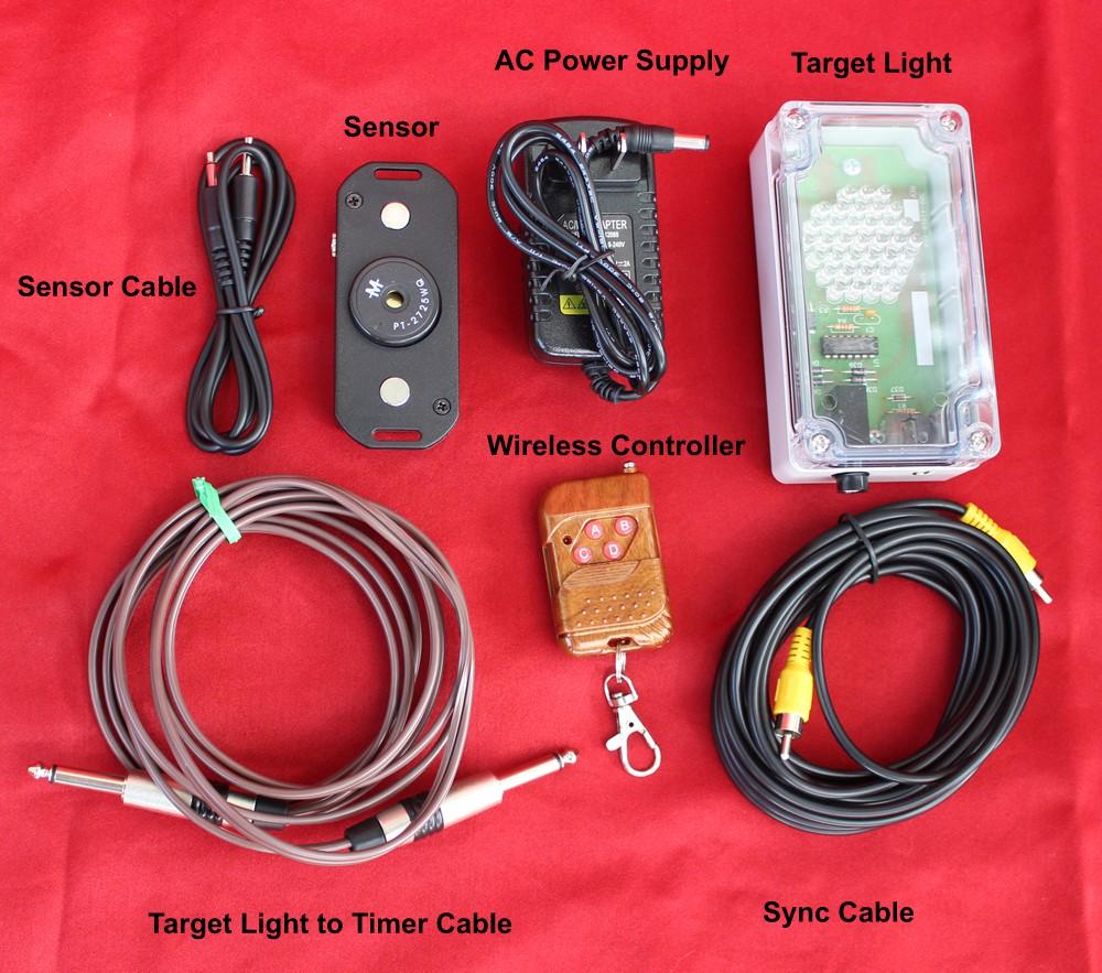
2 QUICKDRAW ELECTRONICS SHOOTING SPORT TIMER SYSTEM THE SYSTEM CONSISTS OF; 1 IMPACT SENSOR 1 LIGHT ASSEMBLY 1 ALL IN ONE TIMER 1 TIMER TO LIGHT CABLE 1 SENSOR TO LIGHT CABLE 1 WIRELESS PUSHBUTTON 1 AC TO 12v DC POWER SUPPLY SETUP SET UP IS QUICK AND EASY. Note: The connection of a plug into the Audio out connection determines if the timer is a Master or Slave. To make the timer work with a wireless remote, it must be made a master timer. The master mode is also necessary to enable the timer to speak. The insertion of the plug into the Audio out opens a switch inside the Audio connector which signals the computer that a plug is connected which enables the master mode.
3 Step 1. Attach the impact sensor and target light to the back of the target. The lights and sensor are held on to the target by magnets. The light enclosure has the magnet mounted on the rear. It is recommended that an L bracket be attached to the rear of the target behind the light hole. It is also recommended that the target light is mounted so that the wires exit the bottom of the light to keep the circuitry in the light dry in case of rain. Step 2. Attach the sensor to the back of the target with the attached magnets. Step 3. Connect the cable from the target light to the sensor. Step 4. Mount the All in One timer above the target so that the digits are visible to the shooter. The timer has two ¼ x 20 nut plates mounted on the inside bottom. The nut plates are spaced 16 ½ inches +/- 1/2 inch apart. The maximum length of bolt inside the timer is 1 inch to avoid damaging the circuitry inside. The timer face is made of Plexiglas. The Plexiglas could crack if hit by a wax bullet multiple times. If the user thinks that the timer could be hit with a wax bullet multiple times, it is recommended to put a piece of Lexan in front of the timer or mount the timer where it is not vulnerable to bullet strikes but still visible to the shooter. The Plexiglas and case is not covered by the warranty. The timer can also be mounted to a camera tripod. The standard camera tripod has a ¼ x 20 screw thread. Step 5. Connect the light to timer cable from the target light on the back of the target to the Target Light connector on the back of the timer. Step 6. Connect the cord of the AC power supply to the 12V DC connector on the back of the timer. Note that the connector on the power supply is center conductor positive. If a power supply of the wrong voltage or polarity is connected, the timer can be damaged. Always use the power supply shipped with the timer. This damage is not covered by the warranty. It is recommended that a strain relief on the power cord be used. The DC power connector is easily pulled loose if it is not held in place by some mechanical means. Step 7. If the timer is the only timer in the setup or going to be the master controller in a multi-timer setup, plug a 1/8 (3.5mm) stereo plug into the Audio Output of the Timer. The presence of the connector plugged into the Audio connector signals the timer to make the timer a master controller. If the user does not want to listen to the audio, the connector can be plugged into the Audio out with the free end connected to nothing. A photo of the recommended connector is shown below. Notice that the connector has two black stripes and three metal connections. The master timer sends the shooters on the line --- shooters set voice command out to the Audio output where it is used by an Audio Amplifier (Public Address system) to enable the shooter to hear the command in Practice Mode. Practice mode is only active when the timer is a master. Step 8. If multiple timers are to be used, connect a sync cable from the sync output of the master timer to the sync input of the next timer in the setup. Continue connecting the sync cable from the sync out of the slave timers to the sync input of the next slave timer.

4 The figure of the multi timer setup should help illustrate the daisy chain connection. Only one timer can be designated as the master timer. Step 8. Connect the AC power supply to a source of VAC power. The setup is complete.
5
6

7 Timer Coding Example
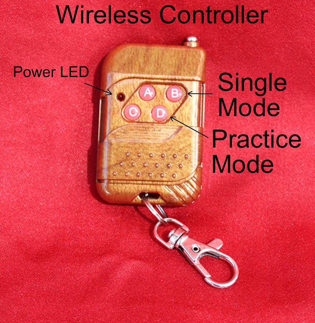
8 MODES Notes: The Wireless Remote Control has an LED on the front that indicates when the remote is transmitting. The LED also indicates Battery condition. If the LED gets dim or the range of the wireless link decreases, replace the battery. The battery is a type 23A 12 volt battery. If you are not intending on using the Practice mode, it is suggested that you slide the cover door on the remote up half way to cover the bottom two buttons so you do not accidentally enter the practice mode. The Timers are coded so that each range has a unique code and one range will not interfere with another just like garage door openers. The code for the Key fob is located on the back. It is marked as Cxx where xx represents the code. For the Timer to respond, the Timer and Key Fob code must match. The code for the timer is located on the back label that shows the Serial Number of the Timer. The Serial number is expressed as S/Nxxxx where x is the Serial Number. The Label also contains the Code expressed as Cxx where xx is the Code for that Timer. Make sure that you are using a Key Fob that matches the Code of the Timer. Master Single MODE The master mode is selected when a 1/8 inch diameter plug is plugged into the Audio output. To start the timer random delay one time, press the upper right button on the wireless remote. The display will show a blank. When the target light illuminates the timer starts. A hit on the target will stop the timer. To restart the system Press the upper right button on the wireless remote. The timer generates a short tone at the same time the timer turns on the target light. To hear the tone, an audio amplifier is connected to the Audio output in Master single mode. If the tone is not desired then disconnect the audio cable from the timer Audio out to the Audio Amplifier or turn down the volume of the Audio Amplifier. The connector still needs to be plugged into the Audio output of the timer but does not have to be connected to the Audio Amplifier if no Audio is desired. Master Practice MODE The master mode is selected when a 1/8 inch diameter plug is plugged into the Audio output. To run the practice mode press the lower right button on the wireless remote the display will blank on the start of the random 2 to 5 second delay. A random delay begins after a random delay, the target light will illuminate and the timer will begin calculating the elapsed time. A hit on the target will display the elapsed time on the timer display otherwise the timer will run to 10 seconds and start the cycle over again. The time display will be blank until a hit is registered by the target sensor. To exit practice mode and go to single mode, press the upper right button on the wireless remote. The first Audio beep from the timer is silent when you go from Practice mode to Single mode. The computer needs to know it is Single mode to prepare the beep signal that goes off when the Target Light comes on.

9 Slave MODE The slave mode is the default mode for the timer. The slave mode is selected when no plug is connected to the Audio out connector. The Timer reads the state of the Audio input when power is turned on to see if a connector is plugged in. If no plug is inserted, the Slave mode is selected. The Master sends, through the slave cable, a Start/Sync command to the timer after a random delay is generated by the master timer. OPTIONAL EQUIPMENT The optional dc power cable may be used with an auxiliary power unit/ or battery. one example of a portable battery can be found at: WARRANTY Quick Draw Electronics warrants to the original consumer, that this product will be free of defects and workmanship for a period of 1 year from the date of purchase when operated under normal conditions. This warranty is limited to the repair or replacement of all parts in the timer system. The timer and its accessories are not warranted against misuse, neglect, tampering, or other causes not arising from defects in material and workmanship.
10 The purchase is automatically registered with Quick Draw Electronics upon purchase. No additional warranty registration is required. NOTES: The impact sensors have been designed, calibrated, and tested to work with the Quick Draw Electronics targets. since we do not have control of the design of user provided targets, we can not guaranty the reliability of the impact sensors on user provided targets. Some users have experienced problems with impact sensor reliability with thin steel target material. We recommend a minimum thickness of 10 gauge (0.134) steel material be used in the construction of targets.
Quick Draw Electronics. Shooting Sports Timer User Manual. Model CLUB All In One
 Quick Draw Electronics Shooting Sports Timer User Manual Model CLUB All In One Rev. C August 2018 QUICKDRAW ELECTRONICS SHOOTING SPORT TIMER SYSTEM THE SYSTEM CONSISTS OF; IMPACT SENSOR LIGHT ASSEMBLY
RD-44 Audio Network Control Panel
 RD-44 Audio Network Control Panel Introduction: The RD-44 is designed to control the audio functions and sources of the MRD-70 marine radio and the MZ-100 DSP Zone Amplifier. With versatile mounting options,
Secured Series: Hub Plus Kit Single Door Controller Package Installation Manual
 Secured Series: Hub Plus Kit Single Door Controller Package Installation Manual This package is designed to simplify the connections to our Secured Series Hub Plus Controller. This will translate into
AEXX-349 SERIES REMOTE DISPLAYS
 FN:349MAN1.DOC AEXX-349 SERIES REMOTE DISPLAYS DESCRIPTION AEXX-349 Series Remote Displays are available with 1, 2.3, 4, 8, or 12 high digits, visible from 5 feet to 500 feet away. They are available in
CU-8R Installation Instructions
 CU-8R Installation Instructions I. Components Model CU-8R is shipped with the following components: QTY Item 1 Stainless Steel Enclosure 2 Lexan Panels 18 Nuts 1 Wall Mount Style Phone with RJ-11 Cable
CC186 AND CC186/2 STAND-ALONE OR SYSTEM CLOCK
 FN:CC186M2.DOC CC186 AND CC186/2 STAND-ALONE OR SYSTEM CLOCK DESCRIPTION The CC186 is a single sided clock with six, 1.8 inch high digits. The CC186/2 is a double sided clock with six, 1.8 inch high digits
Wireless Doorphone Intercom
 Security Made Smarter Wireless Doorphone Intercom EN INSTRUCTION MANUAL DOORBELL OVERVIEW MICROPHONE LEDS CAMERA LENS LIGHT SENSOR Detects ambient light and turns on the LEDS to provide clear color night
PRO REMOTE 25 LV CAPACITANCE PROBE
 Price $5.00 PRO REMOTE 25 LV CAPACITANCE PROBE OPERATING INSTRUCTIONS READ THOROUGHLY BEFORE INSTALLING EQUIPMENT TABLE OF CONTENTS GENERAL SPECIFICATIONS...3 1.0 INTRODUCTION...4 2.0 APPLICATIONS...4
DP-222Q Color Video Door Phone Manual
 DP-222Q Color Video Door Phone Manual * has 6 LEDs for nighttime operation Remotely and securely talk to visitors and unlock doors, gates, etc. from the Easily connect a secondary * Simple 2-wire connection
Basketball Shot Clock Set LX2180 Manual
 Basketball Shot Clock Set LX2180 Manual 72 Industrial Boulevard Wrightsville, GA 31096 Phone: (800) 445-7843 Fax: (800) 864-0212 www.electro-mech.com LX2180 Revision 5 February 8, 2013 Table of Contents
SERIES 5100XXX8 INSTALLATION & SPECIFICATION GUIDE
 SERIES 5100XXX8 INSTALLATION & SPECIFICATION GUIDE Microframe Corporation 604 South 12th Street Local: 918-258-4839 Toll Free: Website: www.microframecorp.com E-mail: support@microframecorp.com Revision
EMS. Electrical Management System. Progressive Industries Incorporated Morrisville, North Carolina
 Progressive Industries Warranty Progressive warrants its products are free from defects in materials and workmanship for a period of three years. This is in lieu of all other warranties, obligations, or
PixController, Inc. Wireless Magnetic Switch Sensor For Doors, Windows, and Gates
 PixController, Inc. Wireless Magnetic Switch Sensor For Doors, Windows, and Gates Model: SEN-420 User s Manual Version 1.00 WARRANTY REGISTRATION PixController, Inc. warrants products sold by it and guarantees
C-POWER AC AUTOMATIC CONTROL
 Issue 1 Print 1 C-POWER AC AUTOMATIC CONTROL INSTALLATION INSTRUCTIONS & OWNER S MANUAL Model: 93 ACMC100I A Charles Industries, Ltd. All rights reserved. Printed in the United States of America. Issue
ple420p 4KHz 6KHz 15KH power in-dash 4 band parametric equalizer
 power 4KHz 6KHz 15KH owner s manual in-dash 4 band parametric equalizer www.pyleaudio.com congratulations... for choosing Pyle Audio, and congratulations on joining a select group of dedicated enthusiasts
AEXX-273 SERIES WIRELESS CONTROLLED PACE CLOCKS
 FN:273MAN1.DOC AEXX-273 SERIES WIRELESS CONTROLLED PACE CLOCKS DESCRIPTION AEXX-273 Series Wireless Controlled Pace Clocks are available in with 1", 2.3", 4", 8", or 12" high digits, visible from 5 feet
SERIES 5100 INSTALLATION & SPECIFICATION GUIDE
 SERIES 5100 INSTALLATION & SPECIFICATION GUIDE Microframe Corporation 604 South 12th Street Local: 918-258-4839 Toll Free: Website: www.microframecorp.com E-mail: support@microframecorp.com Manual No.
212iL Rev. 1.1
 212iL 1 International Electronics, Inc. 427 Turnpike Street Canton, Massachusetts 02021 212iL (illuminated Luxury) Keypad Single Unit Keypad- Control Installation Manual Features: 120 User Capability Illuminated
DP-234Q (NTSC) DP-734Q (PAL) Hands-Free Video Door Phone Manual
 DP-734Q (PAL) Hands-Free Video Door Phone Manual") DP-234Q (NTSC) DP-734Q (PAL) Hands-Free Video Door Phone Manual Screen image simulated. * has four LEDs for nighttime operation Remotely and securely talk to visitors and unlock doors, gates, etc. from
DP-234Q (NTSC) DP-734Q (PAL) Hands-Free Video Door Phone Manual Screen image simulated. * has four LEDs for nighttime operation Remotely and securely talk to visitors and unlock doors, gates, etc. from
AE21 SERIES DISPLAY CONTROL TERMINAL
 FN:AE21MAN1.DOC AE21 SERIES DISPLAY CONTROL TERMINAL DESCRIPTION The AE21 Series Display Control Terminal is used for implementing various display functions. It consists of a control terminal, the AE21,
INSTRUCTION MANUAL DIGI-LOCK. Keyless Entry System. Installation. Programming. Troubleshooting. BASE Industries
 INSTRUCTION MANUAL DIGI-LOCK Keyless Entry System Installation Programming Troubleshooting BASE Industries 45 Pomona Rd. Corona, CA. 9880 Revision F TABLE OF CONTENTS OWNER REGISTRATION CARD INTRODUCTION
SERIES 5100XXCX (WITH VOICE ANNOUNCE OPTION) INSTALLATION & SPECIFICATION GUIDE
 INSTALLATION & SPECIFICATION GUIDE") SERIES 5100XXCX (WITH VOICE ANNOUNCE OPTION) INSTALLATION & SPECIFICATION GUIDE Microframe Corporation 604 South 12th Street Local: 918-258-4839 Toll Free: Website: E-mail: support@microframecorp.com Manual
SERIES 5100XXCX (WITH VOICE ANNOUNCE OPTION) INSTALLATION & SPECIFICATION GUIDE Microframe Corporation 604 South 12th Street Local: 918-258-4839 Toll Free: Website: E-mail: support@microframecorp.com Manual
1. Unpacking the System
 1. Unpacking the System To prevent shipping damage the system is packed in multiple boxes. Chassis The chassis in shipped in one box by itself. The chassis is shipped assembled. Inside the chassis you
GSMR30 OWNER S MANUAL
 GSMR30 OWNER S MANUAL Version 1.0 MP4/MP3/Photo Playback Gauge Series Marine Radio FEATURES 4 Channel Full Range, Class A/B 45W x 4 @ 4Ω IPX5 Water proof INPUTS AND OUTPUTS Bluetooth Audio Streaming Easy
DP-222Q Color Video Door Phone Manual
 DP-222Q Color Video Door Phone Manual * has 6 LEDs for nighttime operation Remotely and securely talk to visitors and unlock doors, gates, etc. from the Easily connect an secondary * Simple 2-wire connection
BRB Systems USA Co. Instruction Manual. USA Trap Solo Voice Release System. 12V & 120V Versions.
 BRB Systems USA Co. Instruction Manual. USA Trap Solo Voice Release System. 12V & 120V Versions. IMPORTANT: Read and understand this manual before assembling, installing or using this system. Improper
Visit us at
 TM PRO3000 Toner and Probe Users Guide 99 Washington Street Melrose, MA 02176 Phone 781-665-1400 Toll Free 1-800-517-8431 Visit us at www.testequipmentdepot.com PN 2440799 (English) October 2005 2005 Fluke
Electrical Management System (EMS) EMS-HW30C & EMS-HW50C
 EMS-HW30C & EMS-HW50C") Electrical Management System (EMS) EMS-HW30C & EMS-HW50C Installation & Operating Guide for: Model EMS-HW30C Rated at 120V/30A and Model EMS-HW50C Rated at 240V/50A Surgio Says Lifetime Warranty on all
Electrical Management System (EMS) EMS-HW30C & EMS-HW50C Installation & Operating Guide for: Model EMS-HW30C Rated at 120V/30A and Model EMS-HW50C Rated at 240V/50A Surgio Says Lifetime Warranty on all
INSTALLATION INSTRUCTIONS
 INSTALLATION INSTRUCTIONS 3YEAR WARRANTY & LIMITATION OF LIABILITY TRI-TRONICS COMPANY, INC. warrants that the products delivered by it will be of the kind and quality described in the order or contract
VG-D70. Vertical / Battery Grip for the Nikon D70
 VG-D70 Vertical / Battery Grip for the Nikon D70 Harbortronics LLC Post Office Box 2663 Gig Harbor, WA. USA 98335 253-858-7769 (Phone) 253-858-9517 (Fax) Sales & Service: Deborah@Harbortronics.com Technical
poly-planar Marine Audio Systems
 ME60BT Bluetooth Amplifier 1 Introduction: The ME60BT is a four channel, 120 Watts RMS Bluetooth wireless audio amplifier, capable of delivering up to 30W RMS per channel. It has a compact, water resistant
AirTest Model CN9000 Series Sensor Controller
 AirTest Model CN9000 Series Sensor Controller AirTest Model CN9000 Series Sensor Controller THEORY OF OPERATION A basic CN9000 configuration consists of Input/Process/Display combination modules, a 3 relay
Pulse Input Adapters (Part # S-UCC/D-M006) for use with HOBO H21 and H22 Series Data Loggers
 for use with HOBO H21 and H22 Series Data Loggers") s (Part # S-UCC/D-M006) for use with HOBO H21 and H22 Series Data Loggers The s are used to log the number of switch closures per interval and are designed to work with smart sensor-compatible HOBO data
s (Part # S-UCC/D-M006) for use with HOBO H21 and H22 Series Data Loggers The s are used to log the number of switch closures per interval and are designed to work with smart sensor-compatible HOBO data
Ag Leader Technology Insight. Direct Command Installation Spra-Coupe 7000 Series
 Note: Indented items indicate parts included in an assembly listed above. Part Name / Description Part Number Quantity Direct Command Spra-Coupe 7000 Kit 4100531 1 Liquid Product Control Module 4000394
SECTION MODEL 2577 INDOOR SCOREBOARD. A. Single-face electronic scoreboard and control console for indoor use.
 SECTION 116643 MODEL 2577 INDOOR SCOREBOARD PART 1 GENERAL 1.01 SECTION INCLUDES A. Single-face electronic scoreboard and control console for indoor use. 1.02 REFERENCES A. Standard for Electric Signs,
The customer will see the blue-green florescent display of the TIMEMASTER, which will be showing the minimum amount needed to start the car wash.
 INTRODUCTION Thank you for purchasing the TIMEMASTER TM-5J. This product has been designed and manufactured to provide years of trouble-free service. The TIMEMASTER housing is water resistant but should
USBCNC USB Disk Key reader for CNC Controls Machine Mount instructions
 USBCNC USB Disk Key reader for CNC Controls Machine Mount instructions 2008-2015 Calmotion LLC, All rights reserved Calmotion LLC 21720 Marilla St. Chatsworth, CA 91311 www.calmotion.com Introduction This
PixController, Inc. Wireless Switch Sensor For Normally Open (NO) and Normally Closed (NC) Sensors
 and Normally Closed (NC) Sensors") PixController, Inc. Wireless Switch Sensor For Normally Open (NO) and Normally Closed (NC) Sensors Model: SEN-410 User s Manual Version 1.00 WARRANTY REGISTRATION PixController, Inc. warrants products
PixController, Inc. Wireless Switch Sensor For Normally Open (NO) and Normally Closed (NC) Sensors Model: SEN-410 User s Manual Version 1.00 WARRANTY REGISTRATION PixController, Inc. warrants products
HL100 Fingerprint Lock User Manual
 HL100 Fingerprint Lock User Manual Version: 1.0 About This Manual This manual introduces the fingerprint lock interface and menu operations for the HL100. For the fingerprint lock installation, see the
AEXX SERIES MULTI-FUNCTION CLOCK/TIMERS
 FN:XXMFCT1.DOC AEXX SERIES MULTI-FUNCTION CLOCK/TIMERS AEXX SERIES MULTI-FUNCTION CLOCK/TIMERS REV 04/09/09 DESCRIPTION The AEXX Series of Multi-Function Clock/Timers are available with 1, 2.3, 4, 8, or
EcoFlex LED Neon Manual
 Manual Part number: LN-ECO-XXXX-10m from Environmental Lights is one of the most flexible and cost-effective members of our line of LED Neon products. It allows you to achieve the creative potential of
Technovision Inc. CD-ROM Audio Sampler. Repair Manual
 Technovision Inc. CD-ROM Audio Sampler Repair Manual Table Of Contents: Page # INITIAL SETUP & TESTING 3 System Components 3 System Set-Up Procedure 3 Self Test Routine 3 REPAIR ACTION PARTS REPLACEMENT
M U L TI - SP ORT SCOREBOARD
 M U L TI - SP ORT SCOREBOARD FEATURES: 24 hour clock display Count up timer with range to 9 hr. 59 min. 59 sec. Presettable countdown timer with loud beep Large 4 inch LCD digits for viewing from as far
232iLM Keypad Installation and Programming Instructions
 232iLM Keypad Installation and Programming Instructions Note: This product is designed to be installed and serviced by security and lock industry professionals. Specifications Case Dimensions: 6 1 / 2
Instruction Manual. Gold Pan Tilt Head with 12V Joystick Control Box (PT-GOLD)
") Instruction Manual Gold Pan Tilt Head with 12V Joystick Control Box (PT-GOLD) All rights reserved No part of this document may be reproduced, stored in a retrieval system, or transmitted by any form or
Instruction Manual Gold Pan Tilt Head with 12V Joystick Control Box (PT-GOLD) All rights reserved No part of this document may be reproduced, stored in a retrieval system, or transmitted by any form or
MODEL KP-100 ACCESS CONTROL DIGITAL KEYPAD OPERATING INSTRUCTIONS
 MODEL KP-100 ACCESS CONTROL DIGITAL KEYPAD OPERATING INSTRUCTIONS Model KP-100 is a self-contained digital keypad. This keypad is suitable for residential, industrial, and commercial installations. It
ipad Charge & Sync Cart Model MCC2 ipad Cart 430-MCC2-User Manual-010 Is a Registered Trademark of Apple Inc. ipad
 ipad Charge & Sync Cart Model MCC2 ipad Cart ipad Is a Registered Trademark of Apple Inc. 430-MCC2-User Manual-010 1. ipad Cart Specifications MCC2 Mobile Charge & Sync Cart Extra Drawer Reserved space
Seeburg JCU-DEC Kit Convert Your Seeburg DEC Wallbox Into a Jukebox
 Seeburg JCU-DEC Kit Convert Your Seeburg DEC Wallbox Into a Jukebox MP3 Compact Flash Player Coin Operated or Free Play Integrated Power Amplifier Line-Out to External Amplifier Programmable Autoplay IR
FEATURES. - COMPATIBLE WITH ALL ipod / MP3 PLAYERS / SATELLITE RADIOS. - SMALL IN OR UNDER DASH CONTROL HEAD WITH 3.5mm HEADPHONE INPUT
 R Thank you for purchasing the Maxxsonics ipod / MP3 interface module. This model allows you to connect your ipod / MP3 music source directly into your aftermarket amplifier with out having to use a radio
AMT-12 AMT-15. Professional Loudspeakers. Installation and Use Manual
 AMT-12 AMT-15 Professional Loudspeakers Installation and Use Manual 2008 Bogen Communications, Inc. Specifications subject to change without notice. 54-2183-01C 0907 Table of Contents Introduction 2 Speaker
Torque Series LCD Remote Panel Installation/Operation Manual Model: TQ-DSP-12/24
 Torque Series LCD Remote Panel Installation/Operation Manual Model: TQ-DSP-12/24 Section Page Introduction 1 Materials Provided 1 I) Safety Instructions 1 A) Inverter Safety Instructions 1 B) Battery Safety
SVP110 SURGE VOLTAGE PROTECTOR INSTRUCTION MANUAL
 SVP110 SURGE VOLTAGE PROTECTOR INSTRUCTION MANUAL REVISION: 01/03/03 COPYRIGHT (c) 1995-2000 CAMPBELL SCIENTIFIC, INC. This is a blank page. WARRANTY AND ASSISTANCE The SVP110 SURGE VOLTAGE PROTECTOR is
MANUAL. Set-up and Operations Guide Glidecam Industries, Inc. 23 Joseph Street, Kingston, MA Customer Service Line
 MANUAL Set-up and Operations Guide Glidecam Industries, Inc. 23 Joseph Street, Kingston, MA 02364 Customer Service Line 1-781-585-7900 Manufactured in the U.S.A. COPYRIGHT 2015 GLIDECAM INDUSTRIES,Inc.
Tactical Weather Station Set-Up Guide 1
 Tactical Weather Station Set-Up Guide 1 This is a generic overview of a portable WEATHERPAK 3 meter tripod set-up. Your system may not include all of the components listed, or may have different components.
Copy Machine Reader. Installation and Setup Guide
 Copy Machine Reader Installation and Setup Guide CONTENTS 1 COPY MACHINE READER INSTALLATION 1 Overview 1 Reader Specifications 3 CR1120/CR1122 INSTALLATION 3 Copier Interface 3 AC Electrical 3 Communications
PRO REMOTE 25 CAPACITANCE PROBE OPERATING INSTRUCTIONS READ THOROUGHLY BEFORE INSTALLING EQUIPMENT Jamieson Equipmen toll free 800
 PRO REMOTE 25 CAPACITANCE PROBE OPERATING INSTRUCTIONS READ THOROUGHLY BEFORE INSTALLING EQUIPMENT TABLE OF CONTENTS GENERAL SPECIFICATIONS...3 1.0 INTRODUCTION...4 2.0 APPLICATIONS...4 3.0 INSTALLATION...4
LH Long Range Business Wireless Doorbell Kit User Manual
 LH-2500 Long Range Business Wireless Doorbell Kit User Manual Warning: This device complies with Part 15 of the FCC rules, operation of this device is subject to the following conditions: 1. This device
LA600WH WIRED / WIRELESS DOOR CHIME
 LA600WH WIRED / WIRELESS DOOR CHIME To register this product, visit: www.nutone.com THIS PACKAGE INCLUDES: Wired / Wireless Door Chime with MP3 upload capability Decorative White Chime Cover USB Cable
Series 803 LED Product Price Display
 Series 803 LED Product Price Display May 2007 Rev. 1.1 1 Installation and Operation Manual Table of contents 1. Safety.......3 2. Series 803 sign features.......4 2.1 Sign descriptions........4 2.2 Control
Installation Instructions
 Alliance Arming Station AL-1111, AL-1116 1048520C September 2006 Copyright 2006, GE Security Inc. Introduction This is the GE Alliance Arming Station for models AL-1111 (four-line LCD) and AL-1116 (four-line
1. Mount the echo and tremolo control switches under the keyboard shelf, in a position convenient for the organist.
 CONSOLE CONNECTOR KIT 8101 INSTALLATION INSTRUCTIONS FOR USE WITH: HAMMOND Organ Models A-100, D-100, RT2, RT3 LESLIE Speaker Models 122, 122RV KIT CONTENT Console Connector Assembly 047357 Echo Control
GSMR20 OWNER S MANUAL
 GSMR20 OWNER S MANUAL Version 1.0 FEATURES AM/FM/Radio/Preset 180 Watts Max Power Pre-Amplifier Outputs Splash Proof LCD Display Bluetooth Audio Streaming (Bluetooth 3.0) A2DP Audio Streaming USB/AUX Input
ANC Series RS-422 Serial Communications Adapter
 Rev. B $ 5.00 ANC - 6000 Series RS-422 Serial Communications Adapter Antona Corporation, Los Angeles, CA Antona Corporation (818)783-4299 FAX (818)783-4216 1 Antona Corporation Copyright Copyright (c)
2-Way Wireless I/O Expander Installation Guide
 2-Way Wireless I/O Expander Installation Guide For more detailed information please refer to the iconnect Installer Manual provided on our website: www.electronics-line.com Table of Contents 1. Introduction...
ELECTRO-MECH SCOREBOARD CO.
 ELECTRO-MECH SCOREBOARD CO. MODEL 2150 SHOT TIMER OWNER S HANDBOOK Thank you for choosing an Electro-Mech Scoreboard for your athletic complex. We are confident that your new shot timer will give many
Rev. A. ANC Series RS-485/RS-422 Synchronous Clock Display. Antona Corporation (818) URL:
 URL:") Rev. A ANC - 7020 Series RS-485/RS-422 Synchronous Clock Display Antona Corporation, Los Angeles, CA Antona Corporation (818)783-4299 URL:http://www.antona.com 1 Antona Corporation Copyright Copyright
Rev. A ANC - 7020 Series RS-485/RS-422 Synchronous Clock Display Antona Corporation, Los Angeles, CA Antona Corporation (818)783-4299 URL:http://www.antona.com 1 Antona Corporation Copyright Copyright
BTU 4 & Sensors. Installation and Operation Manual
 BTU 4 & Sensors Installation and Operation Manual Table of Contents Introduction... 1 Sensors... 1 BTO Outdoor Sensor... 1 BTI Indoor Sensor... 2 BTS Stack Sensor... 2 Installation... 3 BTU 4 Burk Temperature
SVP48 SURGE VOLTAGE PROTECTOR INSTRUCTION MANUAL
 SVP48 SURGE VOLTAGE PROTECTOR INSTRUCTION MANUAL REVISION: 3/03 COPYRIGHT (c) 1995-2003 CAMPBELL SCIENTIFIC, INC. This is a blank page. Warranty and Assistance The SVP48 SURGE VOLTAGE PROTECTOR is warranted
TARA CONTROLS AGC-5. UCI Random Start USER S GUIDE. With Optional Warning Flashes for the Hearing Impaired. TARA CONTROLS by Cartessa Corporation
 TARA CONTROLS AGC-5 UCI Random Start USER S GUIDE With Optional Warning Flashes for the Hearing Impaired TARA CONTROLS by Cartessa Corporation 4825 Cincinnati-Brookville Road Shandon, Ohio 45063 Phone:
Zartek. CDP-808 Two Button Wireless Intercom Installers Manual
 Zartek CDP-808 Two Button Wireless Intercom Installers Manual ZA-614 Two Button Gate station including power supply, relay board and external antenna ZA-613 Handsets with charger ZA-613-E Handsets with
SP-C1 Mobile Docking Station Installation Guide
 SP-C1 Mobile Docking Station Installation Guide Box Contents After you unpack your SP-C1 Mobile Docking Station, make sure everything here is included: 1 x Docking Cradle 1 x Audio Cable 1 x Adhesive Mount
SERVICE MANUAL MODEL WPP-531-X-ADA MODEL SSP-511- X-ADA
 WPP-531-X-ADA OR SSP-511-X-ADA-SPK1.07-ISSUE4.0 SERVICE MANUAL FOR MODEL WPP-531-X-ADA HANDS FREE EMERGENCY WEATHERPROOF TELEPHONE OR MODEL SSP-511- X-ADA HANDS FREE STAINLESS STEEL PANEL TELEPHONE EQUIPPED
Oracle (T M ) W ireless Keypad
 W ireless Keypad") Universal Wireless Solutions Oracle (T M ) W ireless Keypad (5 & 250 PIN VERSIONS) System Features: Model OWK-5/250 4/12/2007 Patents Pending Thank you for purchasing the Oracle Wireless Keypad. This product
Universal Wireless Solutions Oracle (T M ) W ireless Keypad (5 & 250 PIN VERSIONS) System Features: Model OWK-5/250 4/12/2007 Patents Pending Thank you for purchasing the Oracle Wireless Keypad. This product
527F CNC. Retrofit controller for machines made by Fadal Machining Centers. Installation and set-up manual Calmotion LLC
 527F CNC Retrofit controller for machines made by Fadal Machining Centers Installation and set-up manual 2008-2018 Calmotion LLC Calmotion LLC 7536 San Fernando Road Sun Valley, CA 91352 www.calmotion.com
MAXIMA + Series ROTARY LEVEL CONTROL
 Price $5.00 MAXIMA + Series ROTARY LEVEL CONTROL OPERATING INSTRUCTIONS PLEASE READ CAREFULLY Division of Garner Industries 7201 North 98th Street Lincoln, NE 68507-9741 (402) 434-9102 925-0268 TABLE OF
USER MANUAL. MODEL 1225 ParaLink TM Parallel Short Range Modem. SALES OFFICE (301) TECHNICAL SUPPORT (301)
 TECHNICAL SUPPORT (301)") USER MANUAL MODEL 1225 ParaLink TM Parallel Short Range Modem C E R T I F I E D An ISO-9001 Certified Company Part #07M1225-B Doc. #104011UB Revised 9/12/97 SALES OFFICE (301) 975-1000 TECHNICAL SUPPORT
USER MANUAL MODEL 1225 ParaLink TM Parallel Short Range Modem C E R T I F I E D An ISO-9001 Certified Company Part #07M1225-B Doc. #104011UB Revised 9/12/97 SALES OFFICE (301) 975-1000 TECHNICAL SUPPORT
User Guide Attracta Magnetic Lighting
 User Guide Attracta Magnetic Lighting Magnetic Lighting System Models and accessories covered by this manual: UFO ATR-CM Corner Mount Extrusion UFO ATR-SM Surface Mount Extrusion UFO ATR-LG L Shaped Gantry
Electrical Management System (EMS) EMS-HW30C & EMS-HW50C
 EMS-HW30C & EMS-HW50C") Electrical Management System (EMS) EMS-HW30C & EMS-HW50C Installation & Operating Guide for: Model EMS-HW30C Rated at 120V/30A and Model EMS-HW50C Rated at 240V/50A Surgio Says Lifetime Warranty on all
Electrical Management System (EMS) EMS-HW30C & EMS-HW50C Installation & Operating Guide for: Model EMS-HW30C Rated at 120V/30A and Model EMS-HW50C Rated at 240V/50A Surgio Says Lifetime Warranty on all
TVA2.1 2-Channel Digital Amplifier Installation Manual
 TVA2.1 2-Channel Digital Amplifier Installation Manual SAFETY INSTRUCTIONS WARNING: TO REDUCE THE RISK OF FIRE OR ELECTRIC SHOCK, DO NOT EXPOSE THIS APPLIANCE TO RAIN OR MOISTURE. CAUTION: TO REDUCE THE
MSD Enhancer Ignition for the Honda TRX400EX PN /PN 4203
 MSD Enhancer Ignition for the Honda TRX400EX PN 05-00-4203/PN 4203 Parts Included: 1 - Programmable Enhancer Ignition 1 - Y-Splice 1 - MSD Coil Assembly 1 - Black Ground Wire 1 - Ignition Mounting Brackets
SERVICE MANUAL MODEL SSC-301-F (FORMERLY 301-FS) MODEL BLC-301-F (FORMERLY 301-F)
 MODEL BLC-301-F (FORMERLY 301-F)") SSC-301-F OR BLC-301-F-ISSUE4.0 SERVICE MANUAL FOR MODEL SSC-301-F (FORMERLY 301-FS) OR MODEL BLC-301-F (FORMERLY 301-F) CHARGE-A-CALL TELEPHONE Serving the Telephone Industry Since 1930 Communication
SSC-301-F OR BLC-301-F-ISSUE4.0 SERVICE MANUAL FOR MODEL SSC-301-F (FORMERLY 301-FS) OR MODEL BLC-301-F (FORMERLY 301-F) CHARGE-A-CALL TELEPHONE Serving the Telephone Industry Since 1930 Communication
Advanced Distribution Cable Junction Box For Spectra RMS Molded-Case Circuit Breakers with Advanced Feature microentelliguard TM Trip Units
 GE Energy Industrial Solutions GEH-704 Installation Instructions Advanced Distribution Cable Junction Box For Spectra RMS Molded-Case Circuit Breakers with Advanced Feature microentelliguard TM Trip Units
V-9941A ONE ZONE HANDSFREE TALKBACK CONTROL UNIT
 VSP- Issue 4 ONE ZONE HANDSFREE TALKBACK CONTROL UNIT INTRODUCTION The is a One Zone Handsfree Page Unit for use on an Electronic Key system line key position, a PABX loop start trunk port, a dedicated
Instruction Manual. Electrical Management System (EMS) EMS-HW30C & EMS-HW50C
 EMS-HW30C & EMS-HW50C") Instruction Manual Electrical Management System (EMS) EMS-HW30C & EMS-HW50C EMS-HW50C EMS-HW30C! CAUTION These instructions are intended to provide assistance with the installation of this product, and
Instruction Manual Electrical Management System (EMS) EMS-HW30C & EMS-HW50C EMS-HW50C EMS-HW30C! CAUTION These instructions are intended to provide assistance with the installation of this product, and
SECTION MODEL INDOOR SCOREBOARD. A. Four-face electronic scoreboard and control console for indoor use.
 SECTION 116643 MODEL 2650-4 INDOOR SCOREBOARD PART 1 GENERAL 1.01 SECTION INCLUDES A. Four-face electronic scoreboard and control console for indoor use. 1.02 REFERENCES A. Standard for Electric Signs,
MEGA DIAL PANEL Instructions
 2036 Fillmore Street Davenport, Ia. 52804 563-324-1046 www.racedigitaldelay.com MEGA DIAL PANEL Instructions WARRANTY AND DISCLAIMER DIGITAL DELAY ELECTRONICS INC. WARRANTS THE PRODUCTS IT MANUFACTURES
Megatouch FORCE Monitor Chassis Board Replacement
 Megatouch FORCE Monitor Chassis Board Replacement Visit the Merit Industries, Inc. Web site http://www.meritind.com merit industries, inc. PM0337-01 Rev C Table of Contents FORCE Classic Monitor Chassis
E1135C PDU and Pod Upgrade Procedure
 E4030-90010 Rev. B 12/2003 In this Document... Tools Needed, 2 Contents of the Upgrade Kits, 2 Installation Procedures, 4 Verifying the Power Option of the New PDU, 4 Removing the PDU from the Support
Amano (itrt) Intelligent Twin Reader Terminal INSTALLATION MANUAL
 Intelligent Twin Reader Terminal INSTALLATION MANUAL") MODEL NUMBER: XRT910-0-0-AC-XX XRT920-0-0-AC-XX AMANO itrt Amano (itrt) Intelligent Twin Reader Terminal INSTALLATION MANUAL SPECIFICATIONS Working Environment Plastic Housing... Power Designed to work
MODEL NUMBER: XRT910-0-0-AC-XX XRT920-0-0-AC-XX AMANO itrt Amano (itrt) Intelligent Twin Reader Terminal INSTALLATION MANUAL SPECIFICATIONS Working Environment Plastic Housing... Power Designed to work
Wi-Card Skeet-Trap Claymate Operator and User Manual
 Claymate... Technology that Counts Wi-Card Skeet-Trap Claymate Operator and User Manual Page 1 Thank you for purchasing a Promatic Wi-Card Skeet-Trap Claymate. The Promatic Wi-Card Sporting Claymate is
Light as soft as a cloud.
 Light as soft as a cloud. As part of Luxli s Softi series, the LED Ring Light with Camera Mount provides soft, flattering light without harsh shadows. Control the intensity when illuminating your subject
Installation and Operation Guide for PD5200 and PD5300 Automatic Transfer Switch
 Installation and Operation Guide for PD5200 and PD5300 Automatic Transfer Switch PD52 PD52S & PD52DCS PD53-100 te: The PD52S & PD52DCS are provided with LED lights. The GREEN LIGHTS indicate Shore Power
The basic product comes with the IRS5 control board, 3 internal cables, 1 external cable with a 5 volt adapter and a mounting bracket with hardware.
 Please read these instructions and watch the Installation Video before you proceed with the installation of the PC-IRS5-01. Installation Video: http://youtu.be/os98e32vhb4 The PC-IRS5-01 Infrared Receiver
Progressive Industries, Inc. EMS Electrical Management System
 Progressive Industries, Inc. EMS Electrical Management System Complete Installation Guide and Operating Instructions for: Model EMS-LCHW50 Rated at 240V/50A Manufactured by: Progressive Industries, Inc.
Service Manual For. -IP Voice over Internet Protocol -ACH** Handset cord length Inches
 SSP-3-F -ISSUE 4.0 Service Manual For -IP Voice over Internet Protocol -ACH** Handset cord length Inches -M Magnetic Hookswitch -CCH Coiled cord length Feet 5, 0, or 5 -BK Braille Keypad -PBVC Pushbutton
Drive 3G-S ENGLISH. Cellular Signal Booster A Customer Support: Mon-Fri 8 am to 6 pm.
 ENGLISH Drive 3G-S Cellular Signal Booster A512626 ENGLISH!! IT IS VERY IMPORTANT TO POWER YOUR SIGNAL BOOSTER USING A SURGE PROTECTED AC POWER STRIP WITH AT LEAST A 1000 JOULE RATING. FAILURE TO DO THIS
SA SERIES Arlingate Lane, Columbus, Ohio (614)
") SA SERIES 2080 Arlingate Lane, Columbus, Ohio 43228 (614) 850-5000 Sensotec, Inc. SA Series Instruction Manual Sensotec Part Number: 008-0131 - 00 Rev. A: January 1996 Copyright Notice: 2080 Arlingate
SA SERIES 2080 Arlingate Lane, Columbus, Ohio 43228 (614) 850-5000 Sensotec, Inc. SA Series Instruction Manual Sensotec Part Number: 008-0131 - 00 Rev. A: January 1996 Copyright Notice: 2080 Arlingate
eforce 150 Keyless Entry Owner s manual & User s guide For Model 3090
 eforce 150 Keyless Entry Owner s manual & User s guide For Model 3090 This manual contains important operation, maintenance & warranty information. Save this manual for future reference TABLE OF CONTENTS
Now with Picture Memory
 Intrasonic Technology, Inc. Color Video Door Phone / Intercom Installer s Manual Model No.V304KIT-R Now with Picture Memory Please read this manual carefully before the products are installed.technical
AI-102. IR Illuminator. Installation Guide. Rev IP Surveillance
 AI-102 IR Illuminator Installation Guide Rev. 1.1 IP Surveillance Revision History: Rev. 1.0: Initial release Rev. 1.1: Changed effective IR range and power consumption. AI-102 Tube Type Infrared Illuminator